JP2017005385A - Station side device and connection scheme switching method - Google Patents
Station side device and connection scheme switching method Download PDFInfo
- Publication number
- JP2017005385A JP2017005385A JP2015115134A JP2015115134A JP2017005385A JP 2017005385 A JP2017005385 A JP 2017005385A JP 2015115134 A JP2015115134 A JP 2015115134A JP 2015115134 A JP2015115134 A JP 2015115134A JP 2017005385 A JP2017005385 A JP 2017005385A
- Authority
- JP
- Japan
- Prior art keywords
- connection method
- connection
- time
- side device
- switching
- Prior art date
- Legal status (The legal status is an assumption and is not a legal conclusion. Google has not performed a legal analysis and makes no representation as to the accuracy of the status listed.)
- Granted
Links
Images


Abstract
Description
本発明は、時分割多重を組み合わせたPON(Passive Optical Network)におけるポイントツーポイント接続方式とポイントツーマルチポイント接続方式の切替時の動作に対応する局側装置及び加入者側装置に関する技術である。 The present invention relates to a station-side device and a subscriber-side device corresponding to operations at the time of switching between a point-to-point connection method and a point-to-multipoint connection method in a PON (Passive Optical Network) combined with time division multiplexing.
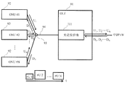
図1に、本発明に関連する時分割多重(TDM:Time Division Multiplexing)を用いたTDM−PONの一例を示す。各加入者側装置(ONU)92は、光ファイバ伝送路94及び光合分波部93を介して、局側装置(OLT)81と接続される。複数のONU92からのOLT81への上り信号は、時間的重なりがないように、固定的もしくは動的に帯域を割り当てられる。これによりOLT81は複数のONU92を収容するポイントツーマルチポイント(PtMP:Point−to−Multipoint)接続を実現している。
FIG. 1 shows an example of TDM-PON using time division multiplexing (TDM) related to the present invention. Each subscriber unit (ONU) 92 is connected to a station side unit (OLT) 81 via an optical
現在、TDM−PONは、マスユーザ向けサービスのアクセスネットワークとして広く普及している。一方で、法人ユーザ向けなどのサービスでは、OLT81とONU92が1対1のポイントツーポイント(PtP:point―to―point)で接続され、TDMを使用しないアクセスネットワークが一般的である。このように、サービス毎に異なるアクセスネットワークを構築する場合、アクセスネットワーク毎に装置やオペレーションシステムが必要となり、費用が増加する。そのため、非特許文献1では、PONを用いたアクセスネットワークにおいて、1台のOLT81が複数のサービスを収容することを提案している。
Currently, TDM-PON is widely used as an access network for services for mass users. On the other hand, for services for corporate users, etc., an access network in which the OLT 81 and the ONU 92 are connected in a one-to-one point-to-point (PtP) manner and does not use TDM is common. As described above, when a different access network is constructed for each service, an apparatus and an operation system are required for each access network, which increases costs. Therefore, Non-Patent
また、非特許文献2では、マルチサービス収容が可能なアクセスネットワークを実現するPONシステムとしてWDM/TDM−PONが提案されている。非特許文献2に係るWDM/TDM−PONシステムでは、波長多重(WDM:Wavelength Division Multiplexing)とTDMを組み合わせ、波長毎に異なるサービスを収容することが可能である。しかし、OLT81は、例えば、ある波長に対しPtP接続で法人ユーザを収容している状況において、ユーザを追加しようとした際には、ONU92との接続を、PtMP接続へ切り替える必要がある。同様にPtMP接続によるマスユーザを収容している波長の中で1ユーザのみ法人ユーザ用にする場合には、OLT81は、ONU92との接続を、PtP接続に切り替える必要がある。
In
PtP接続をしているPONにおいて、2台目以降のONUを接続する場合、PtMP接続となりTDMを適用する必要がある。OLTはTDMに切り替える場合、現在確立している通信を切断して、新たに登録要求を各ONUへ送信し、ONUからの登録応答を受け、ONU識別子を払い出し、各ONUがONU識別子を登録することで、通信が再開される。このため、PtP接続からPtMP接続へ切り替える際、通信断が生じる。 When connecting the second and subsequent ONUs in a PON with PtP connection, it becomes a PtMP connection and it is necessary to apply TDM. When switching to TDM, the OLT disconnects the currently established communication, newly sends a registration request to each ONU, receives a registration response from the ONU, issues an ONU identifier, and each ONU registers the ONU identifier. As a result, communication is resumed. For this reason, when switching from the PtP connection to the PtMP connection, communication disconnection occurs.
また、PtMP接続をしているPONにおいて、ONU数を1台に削減する場合、TDMを継続した状態が続き、本来不要なONUへの帯域を割り当てるための制御用の通信が発生し、帯域に無駄が生じる。 In addition, when the number of ONUs is reduced to one in a PON with a PtMP connection, the TDM continues and the control communication for allocating the bandwidth to the originally unnecessary ONU occurs. Waste occurs.
そこで、本発明では、通信断を発生させることなくPtP接続からPtMP接続への接続方式の切替を可能にするとともに、帯域利用効率を向上するためにPtMP接続からPtP接続への接続方式の切替の自動化を可能にすることを目的とする。 Therefore, in the present invention, it is possible to switch the connection method from the PtP connection to the PtMP connection without causing a communication interruption, and to switch the connection method from the PtMP connection to the PtP connection in order to improve the bandwidth utilization efficiency. The goal is to enable automation.
上記目的を達成するために、本発明では、PtP接続からPtMP接続へ切り替える際、予めPtP接続の状態でTDMに必要なONU識別子の登録を行い、OLTとONUが同じ時間にPtMP接続へ切り替える。また、PtMP接続の状態で、ONUへの接続数が1となった場合に、PtMP接続を継続せずにPtP接続へ切り替える。 In order to achieve the above object, in the present invention, when switching from a PtP connection to a PtMP connection, an ONU identifier necessary for TDM is registered in advance in the PtP connection state, and the OLT and the ONU switch to the PtMP connection at the same time. Further, when the number of connections to the ONU becomes 1 in the PtMP connection state, the PtMP connection is switched to the PtP connection without continuing.
具体的には、本発明に係る局側装置は、
複数の加入者側装置と接続された局側装置であって、
1波長に対し時分割多重を用いて1又は複数の加入者側装置と光信号の送受信を行う光信号送受信部と、
前記加入者側装置において1対1と1対多の接続方式を切替える接続方式切替時間を算出する接続方式切替時間算出部と、
接続方式の切替を行う前記加入者側装置の識別子と共に、前記接続方式切替時間を前記加入者側装置に通知し、前記接続方式切替時間に、前記識別子に対応した前記加入者側装置の接続方式を切り替える接続方式制御部と、
を備える。
Specifically, the station side device according to the present invention is:
A station-side device connected to a plurality of subscriber-side devices,
An optical signal transmission / reception unit for transmitting / receiving an optical signal to / from one or more subscriber-side devices using time division multiplexing for one wavelength;
A connection method switching time calculating unit for calculating a connection method switching time for switching between a one-to-one and a one-to-many connection method in the subscriber side device;
The connection method switching time is notified to the subscriber side device together with the identifier of the subscriber side device for switching the connection method, and the connection method of the subscriber side device corresponding to the identifier is connected to the connection method switching time. A connection method control unit for switching between,
Is provided.
本発明に係る局側装置では、
前記接続方式制御部は、
接続方式の切替を行う前記加入者側装置の識別子及び前記接続方式切替時間を含む登録要求を前記加入者側装置に通知し、
前記加入者側装置の識別子を有する前記加入者側装置から登録完了通知を受信した場合に、前記接続方式切替時間に、前記加入者側装置の識別子の接続方式を切り替えてもよい。
In the station side device according to the present invention,
The connection method control unit
Notifying the subscriber side device of a registration request including an identifier of the subscriber side device that performs connection mode switching and the connection mode switching time,
When a registration completion notification is received from the subscriber side device having the identifier of the subscriber side device, the connection method of the identifier of the subscriber side device may be switched during the connection mode switching time.
本発明に係る局側装置では、
前記接続方式切替時間算出部は、
前記局側装置が前記登録要求を送信してから前記加入者側装置が前記登録要求を受信するまでの時間と、
前記登録要求を受信した前記加入者側装置が前記接続方式切替時間を登録するまでの時間と、
前記加入者側装置が登録完了通知を送信してから前記局側装置が前記登録完了通知を受信するまでの時間と、
を用いて前記接続方式切替時間を算出してもよい。
In the station side device according to the present invention,
The connection method switching time calculation unit
A time from when the station side device transmits the registration request to when the subscriber side device receives the registration request;
The time until the subscriber side device that has received the registration request registers the connection method switching time;
A time from when the subscriber-side device transmits a registration completion notification to when the station-side device receives the registration completion notification;
The connection method switching time may be calculated using.
具体的には、本発明に係る局側装置の接続方式切替方法は、
複数の加入者側装置と接続された局側装置の接続方式切替方法であって、
光信号送受信部が、1波長に対し時分割多重を用いて1又は複数の加入者側装置と光信号の送受信を行い、接続方式切替時間算出部が、前記加入者側装置において1対1と1対多の接続方式を切替える接続方式切替時間を算出し、接続方式制御部が、接続方式の切替を行う前記加入者側装置の識別子と共に、前記接続方式切替時間を前記加入者側装置に通知する接続方式切替時間通知手順と、
接続方式制御部が、前記接続方式切替時間に、前記識別子に対応した前記加入者側装置の接続方式を切り替える接続方式切替手順と、
を実行する。
Specifically, the connection method switching method of the station side device according to the present invention is:
A connection method switching method for a station-side device connected to a plurality of subscriber-side devices,
The optical signal transmission / reception unit transmits / receives an optical signal to / from one or a plurality of subscriber side devices using time division multiplexing for one wavelength, and the connection method switching time calculation unit is one-to-one in the subscriber side device. The connection method switching time for switching the one-to-many connection method is calculated, and the connection method control unit notifies the subscriber side device of the connection method switching time together with the identifier of the subscriber side device for switching the connection method. Connection method switching time notification procedure to
A connection method control unit, a connection method switching procedure for switching the connection method of the subscriber side device corresponding to the identifier at the connection method switching time;
Execute.
本発明によれば、通信断を発生させることなくPtP接続からPtMP接続への接続方式の切替を可能にするとともに、帯域利用効率を向上するためにPtMP接続からPtP接続への接続方式の切替の自動化を可能にすることができる。このため、PtP接続からPtMP接続へ切り替える際の通信断を回避し、サービス断なく接続方式の切替を実現でき、PtMP接続の状態で、ONUへの接続数が1となった場合に、帯域利用効率の向上を実現できる。 According to the present invention, it is possible to switch the connection method from the PtP connection to the PtMP connection without causing a communication interruption, and to switch the connection method from the PtMP connection to the PtP connection in order to improve the bandwidth utilization efficiency. Automation can be enabled. For this reason, communication interruption when switching from PtP connection to PtMP connection can be avoided, switching of connection method can be realized without service interruption, and bandwidth usage is used when the number of connections to ONU becomes 1 in the state of PtMP connection Increase efficiency.
以下、本発明の実施形態について、図面を参照しながら詳細に説明する。なお、本発明は、以下に示す実施形態に限定されるものではない。これらの実施の例は例示に過ぎず、本発明は当業者の知識に基づいて種々の変更、改良を施した形態で実施することができる。なお、本明細書及び図面において符号が同じ構成要素は、相互に同一のものを示すものとする。 Hereinafter, embodiments of the present invention will be described in detail with reference to the drawings. In addition, this invention is not limited to embodiment shown below. These embodiments are merely examples, and the present invention can be implemented in various modifications and improvements based on the knowledge of those skilled in the art. In the present specification and drawings, the same reference numerals denote the same components.
(実施形態1)
(局側装置(OLT)の実施形態)
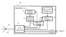
図2に、本実施形態における局側装置(OLT)91の一例を示す。本実施形態に係るOLT91は、信号送受信部11と、帯域割当算出部12と、送信許可送信部13と、登録ONU管理部14と、接続方式切替時間算出部15と、接続方式制御部16を備える。
(Embodiment 1)
(Embodiment of station side device (OLT))
FIG. 2 shows an example of the station side device (OLT) 91 in the present embodiment. The
信号送受信部11は、光ファイバ伝送路94及び光合分波部93を介して加入者側装置(ONU)92と光信号を送受信する。信号送受信部11は、1波長に対し時分割多重を用いて1又は複数のONU92と光信号の送受信を行う。帯域割当算出部12は、登録ONU管理部14に記録しているONU識別子に対して、各ONU92からOLT91への光信号の送信時間Tsを算出する。ここで、送信時間Tsは、送信を開始するタイミング及び送信を継続する時間幅の情報を含む。送信を開始するタイミングは、例えば、時刻又は周期である。送信を継続する時間幅は、例えば、送信継続時間又は周期である。
The signal transmission /
送信許可送信部13は、ONU92に、帯域割当算出部12で算出した送信時間Tsを指示する。登録ONU管理部14は、OLT91と接続している各ONU92に対して、ONU識別子を割り当て記録する、もしくは記録したONU識別子を削除する。
The transmission permission transmission unit 13 instructs the
接続方式切替時間算出部15は、OLT91とONU92との接続方式を切り替える際の接続方式の切替時間を算出する。接続方式制御部16は、OLT91とONU92の間の接続方式の切替シーケンスを制御する。
The connection method switching time calculation unit 15 calculates the connection method switching time when the connection method between the
(PtP接続からPtMP接続への切替動作)
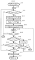
図3に、本実施形態におけるPtP接続方式からPtMP接続方式への切替シーケンスを示す。また、図4及び図5に、本実施形態におけるOLT91とONU92が実行するフローチャートの例を示す。本実施形態では、OLT91とONU92#1がPtP接続方式で接続している状態において、OLT91との接続にONU92#2を追加する場合に、OLT91及びONU92#1は以下のシーケンスを実行する。
(Switching operation from PtP connection to PtMP connection)
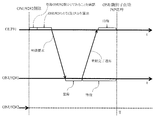
FIG. 3 shows a switching sequence from the PtP connection method to the PtMP connection method in the present embodiment. 4 and 5 show examples of flowcharts executed by the
本実施形態に係るOLT91の接続方式切替方法は、接続方式切替時間通知手順と、接続方式切替手順と、を順に実行する。接続方式切替時間通知手順では、OLT91が、ステップS101〜S108を実行する。接続方式切替手順では、OLT91が、ステップS109〜S113を実行する。
The connection method switching method of the
接続方式制御部16は、PtP接続方式からPtMP接続方式への切替シーケンスを開始すると(S101)、切替試行回数nを1とする(S102)。
(1)接続方式制御部16は、OLT91の接続方式がPtP接続方式であることを確認し(S103でYes)、接続方式切替時間算出部15は、PtMP接続方式へ切り替える接続方式切替時間Tcを算出する(S104)。ここで、接続方式切替時間Tcは切替を開始するタイミングの情報を含む。切替を開始するタイミングは、例えば、時刻又は周期である。
When the connection
(1) The connection
接続方式切替時間算出部15は、PtMP接続方式への接続方式切替時間Tcを、現在時間tから、ONU92#1がOLT91から接続方式切替時間Tcの通知を受信するまでの時間と、ONU92がOLT91から受信した接続方式切替時間Tcを登録するまでの時間と、OLT91がONU92から登録完了通知を受信するまでの時間との和で求められる時間を経過した時点になるように算出する。OLT91の接続方式がPtP接続方式でない場合には(S103でNo)、接続方式制御部16は、本シーケンスを終了する。
The connection method switching time calculation unit 15 sets the connection method switching time Tc to the PtMP connection method from the current time t until the
(2)登録ONU管理部14は、現在、OLT91が接続しているONU92#1にONU識別子を付与し、登録する(S105)。
(3)信号送受信部11は、(1)及び(2)より求めた接続方式切替時間TcとONU識別子を、接続しているONU92#1へ送信する(S106)。
(2) The registered
(3) The signal transmission /
接続方式制御部16は、切替試行回数nに1を加える(S107)。接続方式制御部16は、切替試行回数nが切替試行上限回数m未満であれば(S108でYes)、ONU92からの返信を待つ(S109)。接続方式制御部16は、切替試行回数nが切替試行上限回数m以上であれば(S108でNo)、本シーケンスを終了する。
The connection
接続方式制御部16は、ONU92#1からの返信を受信していなければ(S109でNo)、所定の待機時間sだけ待機する(S121)。接続方式制御部16は、ONU92#1からの返信を、現在時間tが、接続方式切替時間Tcを超えるまで待つ(S122でYes)。現在時間tが、接続方式切替時間Tcを超えると(S122でNo)、接続方式制御部16は、本シーケンスを終了する。
If the reply from the
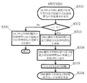
(4)ONU92#1は、OLT91よりONU識別子及び接続方式切替時間Tcの登録要求を受信すると、PtP接続方式からPtMP接続方式への切替シーケンスを開始する(S131)。ONU92#1は、受信した接続方式切替時間Tcが、ONU92#1が保持する現在時間tよりも後であることを確認し(S132でYes)、接続方式切替時間Tc及びONU識別子を登録し(S133)、登録完了通知をOLT91へ送信する(S134)。
(4) When the
接続方式制御部16は、ONU92#1からの返信が登録完了通知である場合(S110でYes)、現在時間tが、接続方式切替時間Tcより前であることを確認すると(S111でYes)、現在時間tが接続方式切替時間Tcとなるまで待機する(S112)。接続方式制御部16は、現在時間tが、接続方式切替時間Tcより後である場合(S111でNo)、S103へと移行する。
When the reply from the
ONU92#1が受信した接続方式切替時間Tcが、ONU92#1が保持する現在時間tよりも前だった場合は(S132でNo)、ONU92#1は、接続方式切替時間Tcの登録不可通知をOLT91へ送信する(S137)。接続方式制御部16は、ONU92#1から接続方式切替時間Tcの登録不可通知を受信すると(S110でNo)、S103へと移行する。
When the connection method switching time Tc received by the
(5)ONU92#1から登録完了通知を受信した接続方式制御部16は、接続方式切替時間Tcまで待機し(S112)、接続方式切替時間TcにPtMP接続方式への切替を実施する(S113)。ONU92#1は接続方式切替時間Tcまで待機し(S135)、接続方式切替時間TcにPtMP接続方式への切替を実施する(S136)。
(5) The connection
(6)ONU92#1が、接続方式切替時間Tcの登録ができず、(1)〜(6)のシーケンスをある予め定めた切替試行上限回数mだけ繰り返した場合には、本シーケンスを終了する(S108でNo)。
(6) When the
本実施形態では、OLT91は、PtP接続からPtMP接続へ切り替える際、予めPtP接続の状態でTDMに必要なONU識別子の登録を行い、OLT91とONU92が同じ時間にPtP接続からPtMP接続へ切り替える。このため、通信断を回避し、サービス断なく接続方式の切替を実現することができる。
In this embodiment, when the
(実施形態2)
(PtMP接続からPtP接続への切替動作 1)
図6に、本実施形態における、接続ONU92の台数が複数台から1台まで減少した際のPtMP接続方式からPtP接続方式への切替シーケンスを示す。図7及び図8に、本実施形態におけるOLT91とONU92#1が実行するフローチャートの例を示す。OLT91とONU92#1及びONU92#2がPtMP接続方式で接続している状態において、ONU92#2が削除されると、OLT91及びONU92#1は以下のシーケンスを実行する。
(Embodiment 2)
(Switching operation from PtMP connection to PtP connection 1)
FIG. 6 shows a switching sequence from the PtMP connection method to the PtP connection method when the number of
本実施形態に係るOLT91の接続方式切替方法は、接続方式切替時間通知手順と、接続方式切替手順と、を順に実行する。接続方式切替時間通知手順では、OLT91が、ステップS201〜S208を実行する。接続方式切替手順では、OLT91が、ステップS209〜S212を実行する。
The connection method switching method of the
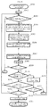
(1)接続方式制御部16は、登録ONU管理部14に記録しているONU識別子が1つであることを確認する(S201)。接続方式制御部16は、切替試行回数nを1とする(S202)。
(1) The connection
(2)接続方式制御部16は、OLT91の接続方式がPtMP接続方式であることを確認し(S203でYes)、接続方式切替時間算出部15は、PtP接続方式に切り替える接続方式切替時間Tc及びONU識別子を削除するONU識別子削除時間Tdを算出する(S204)。OLT91の接続方式がPtMP接続方式でない場合には(S203でNo)、接続方式制御部16は、本シーケンスを終了する。
(2) The connection
ここで、ONU識別子削除時間Tdは、ONU識別子を削除するタイミングの情報を含む。ONU識別子を削除するタイミングは、例えば、時刻又は周期である。ONU識別子を削除するタイミングは、例えば、接続方式切替時間Tcと同時又は接続方式の切替後である。接続方式の切替完了後の場合、接続方式切替時間Tcに所定の時間を経過した時間をONU識別子削除時間Tdとする。本実施形態においては、ONU識別子削除時間Tdが接続方式切替時間Tcと同時である、すなわちT=Tc=Tdの場合について説明する。 Here, the ONU identifier deletion time Td includes information on timing for deleting the ONU identifier. The timing for deleting the ONU identifier is, for example, time or period. The timing for deleting the ONU identifier is, for example, at the same time as the connection method switching time Tc or after the connection method is switched. When the connection method switching is completed, a time when a predetermined time has elapsed in the connection method switching time Tc is set as an ONU identifier deletion time Td. In the present embodiment, the case where the ONU identifier deletion time Td is the same as the connection method switching time Tc, that is, T = Tc = Td will be described.
(3)信号送受信部11は、(2)で求めた接続方式切替時間Tc及びONU識別子削除時間Tdを接続しているONU92#1へ送信する(S205)。接続方式制御部16は、切替試行回数nに1を加える(S206)。
(3) The signal transmission /
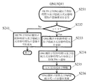
(4)ONU92#1は、OLT91から接続方式切替時間Tc及びONU識別子削除時間Tdを受信すると、シーケンスを開始する(S231)。ONU92#1は、受信した接続方式切替時間Tc及びONU識別子削除時間Tdが、ONU92#1が保持する現在時間tよりも後であることを確認する(S232でYes)。
(4) When receiving the connection method switching time Tc and the ONU identifier deletion time Td from the
接続方式切替時間Tc及びONU識別子削除時間Tdが現在時刻tよりも前だった場合(S232でYes)、ONU92#1は、接続方式切替時間Tc及びONU識別子削除時間Tdを登録し(S233)、登録完了通知をOLT91へ送信する(S234)。そして、ONU92#1は、接続方式切替時間Tc及びONU識別子削除時間Tdまで待機し(S235)、接続方式切替時間Tc及びONU識別子削除時間Tdに、PtP接続方式への切替及びONU識別子の削除を実施する(S236)。
When the connection method switching time Tc and the ONU identifier deletion time Td are before the current time t (Yes in S232), the
接続方式切替時間Tc及びONU識別子削除時間Tdが現在時間tよりも前だった場合は(S232でYes)、ONU92#1は、接続方式切替時間Tc及びONU識別子削除時間Tdの登録不可通知をOLT91へ送信する(S241)。
If the connection method switching time Tc and the ONU identifier deletion time Td are earlier than the current time t (Yes in S232), the
切替試行回数nが切替試行上限回数m未満であり(S207でYes)、ONU92#1からの返信を受信していなければ(S208でNo)、接続方式制御部16は、所定の待機時間sだけ待機する(S221)。ここで、待機時間sは、時間に限らず周期であってもよい。接続方式制御部16は、ONU92#1からの返信を、現在時間tが、接続方式切替時間Tcを超えるまで待つ(S222でYes)。現在時間tが、接続方式切替時間Tcを超えると(S222でNo)、接続方式制御部16は、本シーケンスを終了する。
If the switching trial count n is less than the switching trial upper limit count m (Yes in S207) and no reply has been received from the
(5)OLT91が登録完了通知を受信した場合(S209でYes)、接続方式制御部16は、現在時間tが接続方式切替時間Tc及びONU識別子削除時間Tdよりも前であることを確認する(S210)。
現在時間tが接続方式切替時間Tc及びONU識別子削除時間Tdよりも前である場合(S210でYes)、接続方式制御部16は、接続方式切替時間及びONU識別子削除時間Tdまで待機し(S211)、接続方式切替時間及TcびONU識別子削除時間TdにOLT91とONU92の間の接続方式のPtP接続方式への切替及びONU識別子の削除を実施する(S212)。
現在時間tが接続方式切替時間Tc及びONU識別子削除時間Tdよりも後である場合(S210でNo)、接続方式制御部16は、再びOLT91の接続方式がPtMP接続方式であることを確認し(S203でYes)、接続方式切替時間算出部15は、PtP接続方式に切り替える接続方式切替時間Tc及びONU識別子を削除するONU識別子削除時間Tdを算出する(S204)。
OLT91が登録不可通知を受信した場合(S209でNo)、ステップS203へ移行する。
(5) When the
When the current time t is before the connection method switching time Tc and the ONU identifier deletion time Td (Yes in S210), the connection
When the current time t is later than the connection method switching time Tc and the ONU identifier deletion time Td (No in S210), the connection
When the
(6)ONU92#1が接続方式切替時間Tc及びONU識別子削除時間Tdの登録ができず、ステップS203〜S205をある予め定めた切替試行上限回数mだけ繰り返した場合には(S207でNo)、接続方式制御部16は、本シーケンスを終了する。
(6) When the
本実施形態では、OLT91は、OLT91とONU92との接続がPtMP接続の状態で、ONU92のOLT91への接続数が1となった場合に、PtMP接続を継続せずにPtP接続へ切り替える。このため、PtMP接続時にTDMによって必要となる帯域割当のための制御通信が不要となり、帯域利用効率の向上を実現できる。
In the present embodiment, the
(実施形態3)
(PtMP接続からPtP接続への切替動作 2)
図9に、本実施形態における、接続ONU92数が複数台の状態において、PtMP接続方式からPtP接続方式への切替シーケンスを示す。図10〜図12に、本実施形態における、OLT91とONU92が実行するフローチャートの例を示す。OLT91とONU92#1〜ONU92#NがPtMP接続方式で接続している状態において、接続方式制御部16が、ONU92#1とPtP接続方式を選択するよう指示すると、OLT91及びONU92#1〜ONU92#Nは以下のシーケンスを実行する。本実施形態においても、実施形態2と同様に、ONU識別子削除時間Tdが接続方式切替時間Tcと同時である、すなわちT=Tc=Tdの場合について説明する。
(Embodiment 3)
(Switching operation from PtMP connection to PtP connection 2)
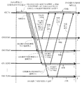
FIG. 9 shows a switching sequence from the PtMP connection method to the PtP connection method when there are a plurality of
本実施形態に係るOLT91の接続方式切替方法は、接続方式切替時間通知手順と、接続方式切替手順と、を順に実行する。接続方式切替時間通知手順では、OLT91が、ステップS301〜S309を実行する。接続方式切替手順では、OLT91が、ステップS310〜S314を実行する。
The connection method switching method of the
(1)接続方式制御部16は、シーケンスを開始すると(S301)、切替試行回数nを1とする(S302)。接続方式制御部16がOLT91の接続方式がPtMP接続方式であることを確認すると(S303でYes)、接続方式切替時間算出部15は、ONU92#1に対する接続方式切替時間Tc及びONU識別子削除時間Td及びONU92#2〜ONU92#Nに対するONU識別子削除時間Tdを算出する(S304)。接続方式制御部16は、OLT91の接続方式がPtMP接続方式でない場合には(S303でNo)、本シーケンスを終了する。
(1) When starting the sequence (S301), the connection
(2)信号送受信部11は、(1)で求めた接続方式切替時間Tc及びONU識別子削除時間Tdを、OLT91に接続しているONU92#1へ送信し(S305)、ONU識別子削除時間TdをONU92#2〜ONU92#Nへ送信する(S306、S307)。
(2) The signal transmitting / receiving
(3)ONU92#1は、OLT91から接続方式切替時間Tc及びONU識別子削除時間Tdを受信すると、シーケンスを開始する(S331)。ONU92#1は、受信したPtP接続方式への接続方式切替時間Tc及びONU識別子削除時間Tdが、ONU92#1が保持する現在時間tよりも後であることを確認し(S332でYes)、PtP接続方式への接続方式切替時間Tc及びONU識別子削除時間Tdを登録し(S333)、登録完了通知をOLT91へ送信する(S334)。
(3) When receiving the connection method switching time Tc and the ONU identifier deletion time Td from the
ONU92#1は、PtP接続方式への接続方式切替時間Tc及びONU識別子削除切替時間Tdまで待機し(S335)、PtP接続方式への接続方式切替時間Tc及びONU識別子削除時間TdにPtP接続方式への切替及びONU識別子の削除を実施する(S336)。PtP接続方式への接続方式切替時間Tc及びONU識別子削除時間Tdが、ONU92#1が保持する現在時間tよりも前だった場合は(S332でNo)、ONU92#1は、PtP接続方式への接続方式切替時間Tc及びONU識別子削除時間Tdの登録不可通知をOLT91へ送信する(S341)。
The
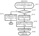
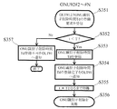
ONU92#2〜ONU92#Nは、OLT91からONU識別子削除時間Tdを受信すると、シーケンスを開始する(S351)。ONU92#2〜ONU92#Nは、受信したONU識別子削除時間Tdが、ONU92#2〜ONU92#Nの保持する現在時間tよりも後であることを確認し(S352でYes)、ONU識別子削除時間Tdを登録し(S353)、登録完了通知をOLT91へ送信し(S354)、ONU識別子削除時間Tdまで待機し(S355)、ONU識別子削除時間TdにONU識別子の削除を実施する(S356)。ONU識別子削除時間が、ONU92#2〜ONU92#Nの保持する現在時間tよりも前だった場合は(S352でNo)、ONU識別子削除時間Tdの登録不可通知をOLT91へ送信する(S357)。
ONU92 # 2-ONU92 # N will start a sequence, if ONU identifier deletion time Td is received from OLT91 (S351). The
(4)登録完了通知を受信した接続方式制御部16は(S310でYes)、登録不可通知を受信しておらず(S311でYes)、現在時間tが接続方式切替時間Tcを超えていなければ(S312でYes)、PtP接続方式への接続方式切替時間Tc及びONU識別子削除時間Tdまで待機し(S313)、PtP接続方式への接続方式切替時間Tc及びONU識別子削除時間TdにPtP接続方式への切替を実施する(S314)。少なくとも1つのONU92から登録不可通知を受信した接続方式制御部16は(S311でNo)、(1)のシーケンスへ移行する。
(4) The connection
(5)ONU92#1がPtP接続方式への接続方式切替時間Tc及びONU識別子削除時間Tdの登録ができない、またはONU92#2〜ONU92#Nのうち1つでもONU識別子削除時間の登録ができず、(1)〜(5)のシーケンスをある予め定めた切替試行上限回数mだけ繰り返した場合には(S309でNo)、本シーケンスを終了する。
(5) The
本実施形態では、OLT91は、OLT91とONU92との接続がPtMP接続の状態で、OLT91が特定のONU92のみとの接続を行う際に、PtMP接続を継続せずにPtP接続へ切り替える。このため、PtMP接続時にTDMによって必要となる帯域割当のための制御通信が不要となり、帯域利用効率の向上を実現できる。
In this embodiment, the
実施形態1〜3は、TDMを使用したPONとして、例えば、NG−PON2や10G−EPON、GE−PON、XG−PON、G−PONを用いることで実現することができる。 The first to third embodiments can be realized by using, for example, NG-PON2, 10G-EPON, GE-PON, XG-PON, and G-PON as the PON using TDM.
本発明の局側装置及び接続方式切替方法は情報通信産業に適用することができる。 The station side apparatus and connection method switching method of the present invention can be applied to the information communication industry.
11:信号送受信部
12:帯域割当算出部
13:送信許可送信部
14:登録ONU管理部
15:接続方式切替時間算出部
16:接続方式制御部
81:OLT
91:OLT
92:ONU
93:光合分波部
94:光ファイバ伝送路
11: Signal transmission / reception unit 12: Bandwidth allocation calculation unit 13: Transmission permission transmission unit 14: Registration ONU management unit 15: Connection method switching time calculation unit 16: Connection method control unit 81: OLT
91: OLT
92: ONU
93: Optical multiplexing / demultiplexing unit 94: Optical fiber transmission line
Claims (4)
1波長に対し時分割多重を用いて1又は複数の加入者側装置と光信号の送受信を行う光信号送受信部と、
前記加入者側装置において1対1と1対多の接続方式を切替える接続方式切替時間を算出する接続方式切替時間算出部と、
接続方式の切替を行う前記加入者側装置の識別子と共に、前記接続方式切替時間を前記加入者側装置に通知し、前記接続方式切替時間に、前記識別子に対応した前記加入者側装置の接続方式を切り替える接続方式制御部と、
を備える局側装置。 A station-side device connected to a plurality of subscriber-side devices,
An optical signal transmission / reception unit for transmitting / receiving an optical signal to / from one or more subscriber-side devices using time division multiplexing for one wavelength;
A connection method switching time calculating unit for calculating a connection method switching time for switching between a one-to-one and a one-to-many connection method in the subscriber side device;
The connection method switching time is notified to the subscriber side device together with the identifier of the subscriber side device for switching the connection method, and the connection method of the subscriber side device corresponding to the identifier is connected to the connection method switching time. A connection method control unit for switching between,
A station side device comprising:
接続方式の切替を行う前記加入者側装置の識別子及び前記接続方式切替時間を含む登録要求を前記加入者側装置に通知し、
前記加入者側装置の識別子を有する前記加入者側装置から登録完了通知を受信した場合に、前記接続方式切替時間に、前記加入者側装置の識別子の接続方式を切り替える、
請求項1に記載の局側装置。 The connection method control unit
Notifying the subscriber side device of a registration request including an identifier of the subscriber side device that performs connection mode switching and the connection mode switching time,
When a registration completion notification is received from the subscriber side device having the identifier of the subscriber side device, the connection method of the identifier of the subscriber side device is switched during the connection method switching time.
The station side apparatus of Claim 1.
前記局側装置が前記登録要求を送信してから前記加入者側装置が前記登録要求を受信するまでの時間と、
前記登録要求を受信した前記加入者側装置が前記接続方式切替時間を登録するまでの時間と、
前記加入者側装置が登録完了通知を送信してから前記局側装置が前記登録完了通知を受信するまでの時間と、
を用いて前記接続方式切替時間を算出する、
請求項1又は2に記載の局側装置。 The connection method switching time calculation unit
A time from when the station side device transmits the registration request to when the subscriber side device receives the registration request;
The time until the subscriber side device that has received the registration request registers the connection method switching time;
A time from when the subscriber-side device transmits a registration completion notification to when the station-side device receives the registration completion notification;
The connection method switching time is calculated using
The station side apparatus of Claim 1 or 2.
光信号送受信部が、1波長に対し時分割多重を用いて1又は複数の加入者側装置と光信号の送受信を行い、接続方式切替時間算出部が、前記加入者側装置において1対1と1対多の接続方式を切替える接続方式切替時間を算出し、接続方式制御部が、接続方式の切替を行う前記加入者側装置の識別子と共に、前記接続方式切替時間を前記加入者側装置に通知する接続方式切替時間通知手順と、
接続方式制御部が、前記接続方式切替時間に、前記識別子に対応した前記加入者側装置の接続方式を切り替える接続方式切替手順と、
を実行する局側装置の接続方式切替方法。 A connection method switching method for a station-side device connected to a plurality of subscriber-side devices,
The optical signal transmission / reception unit transmits / receives an optical signal to / from one or a plurality of subscriber side devices using time division multiplexing for one wavelength, and the connection method switching time calculation unit is one-to-one in the subscriber side device The connection method switching time for switching the one-to-many connection method is calculated, and the connection method control unit notifies the subscriber side device of the connection method switching time together with the identifier of the subscriber side device for switching the connection method. Connection method switching time notification procedure to
A connection method control unit, a connection method switching procedure for switching the connection method of the subscriber side device corresponding to the identifier at the connection method switching time;
The connection method switching method of the station side device that executes
Priority Applications (1)
| Application Number | Priority Date | Filing Date | Title |
|---|---|---|---|
| JP2015115134A JP6342847B2 (en) | 2015-06-05 | 2015-06-05 | Station side device and connection method switching method |
Applications Claiming Priority (1)
| Application Number | Priority Date | Filing Date | Title |
|---|---|---|---|
| JP2015115134A JP6342847B2 (en) | 2015-06-05 | 2015-06-05 | Station side device and connection method switching method |
Publications (2)
| Publication Number | Publication Date |
|---|---|
| JP2017005385A true JP2017005385A (en) | 2017-01-05 |
| JP6342847B2 JP6342847B2 (en) | 2018-06-13 |
Family
ID=57752349
Family Applications (1)
| Application Number | Title | Priority Date | Filing Date |
|---|---|---|---|
| JP2015115134A Active JP6342847B2 (en) | 2015-06-05 | 2015-06-05 | Station side device and connection method switching method |
Country Status (1)
| Country | Link |
|---|---|
| JP (1) | JP6342847B2 (en) |
Cited By (1)
| Publication number | Priority date | Publication date | Assignee | Title |
|---|---|---|---|---|
| WO2021179846A1 (en) * | 2020-03-07 | 2021-09-16 | 中兴通讯股份有限公司 | Registration method and device, method for writing registration information, optical line terminal, and optical network unit |
Citations (3)
| Publication number | Priority date | Publication date | Assignee | Title |
|---|---|---|---|---|
| JP2002271355A (en) * | 2001-03-13 | 2002-09-20 | Nec Corp | Packet communication system, identifier allocation method, and net-side apparatus |
| WO2009057392A1 (en) * | 2007-11-01 | 2009-05-07 | Nippon Telegraph And Telephone Corporation | Optical network unit |
| JP2015019237A (en) * | 2013-07-10 | 2015-01-29 | 日本電信電話株式会社 | Dynamic wavelength band allocation method |
-
2015
- 2015-06-05 JP JP2015115134A patent/JP6342847B2/en active Active
Patent Citations (3)
| Publication number | Priority date | Publication date | Assignee | Title |
|---|---|---|---|---|
| JP2002271355A (en) * | 2001-03-13 | 2002-09-20 | Nec Corp | Packet communication system, identifier allocation method, and net-side apparatus |
| WO2009057392A1 (en) * | 2007-11-01 | 2009-05-07 | Nippon Telegraph And Telephone Corporation | Optical network unit |
| JP2015019237A (en) * | 2013-07-10 | 2015-01-29 | 日本電信電話株式会社 | Dynamic wavelength band allocation method |
Non-Patent Citations (2)
| Title |
|---|
| 吉田 智暁 他: "波長可変型WDM/TDM−PONにおける動的波長切替方式の提案", 電子情報通信学会2013年総合大会講演論文集 通信2, JPN6018017291, 5 March 2013 (2013-03-05), pages 2 - 3 * |
| 栖川 淳 他: "プログラマブル性を備えたWDM/TDM−PONシステムの評価", 電子情報通信学会技術研究報告, vol. 第114巻,第289号, JPN6018017290, 30 October 2014 (2014-10-30), pages 43 - 48 * |
Cited By (1)
| Publication number | Priority date | Publication date | Assignee | Title |
|---|---|---|---|---|
| WO2021179846A1 (en) * | 2020-03-07 | 2021-09-16 | 中兴通讯股份有限公司 | Registration method and device, method for writing registration information, optical line terminal, and optical network unit |
Also Published As
| Publication number | Publication date |
|---|---|
| JP6342847B2 (en) | 2018-06-13 |
Similar Documents
| Publication | Publication Date | Title |
|---|---|---|
| US9960879B2 (en) | Optical line terminal communication method and device with data structure | |
| JP5773387B2 (en) | Transmission control device, transmission control program, and termination device | |
| US10027405B2 (en) | Method and device for channel switching, optical network unit, and time wavelength division multiplexing system | |
| CN102882801B (en) | Automatic wavelength tuning method and automatic wavelength tuning system based on TWDM-PON (time wavelength division multiplexing-passive optical network) | |
| JP5460886B2 (en) | Logical link management method and communication apparatus | |
| JP2019097108A (en) | Optical transmission device, optical transmission system and optical transmission method | |
| JP5556921B1 (en) | Subscriber side apparatus registration method and optical network system | |
| JPWO2014050898A1 (en) | Optical wireless access system | |
| TW201824783A (en) | Data Communication System, Optical Line Terminal and Baseband Unit | |
| KR20150022859A (en) | Optical network terminal management control interface message transmission method and system, and corresponding device | |
| US20220256264A1 (en) | Communication Method Based on Passive Optical Network, Related Device, and System | |
| JP2008072534A (en) | Pon system | |
| WO2016169406A1 (en) | Registration method and apparatus | |
| JP6342847B2 (en) | Station side device and connection method switching method | |
| JP5725226B1 (en) | Dynamic wavelength allocation control method and station side apparatus | |
| JP5879776B2 (en) | Station side device, optical communication network, and power supply control method | |
| JP6542715B2 (en) | Transmission control method and communication system | |
| CN106464385B (en) | Communication method, device and system | |
| JP7196680B2 (en) | Optical communication system and wavelength switching method for optical communication system | |
| JP6756688B2 (en) | Optical communication system, wavelength resource management method and accommodation station side equipment | |
| JP2014183344A (en) | Method for registering subscriber side device | |
| KR20140068779A (en) | Time and wavelength division multiplexing - passive optical network (TWDN-PON) system and communication connection method in the TWDM-PON system | |
| US9094150B2 (en) | Method for registering optical network unit in telecommunications network and optical network unit therefor | |
| JP5484308B2 (en) | Station side communication equipment | |
| JP6547520B2 (en) | Optical communication apparatus, optical communication network system, and optical communication program |
Legal Events
| Date | Code | Title | Description |
|---|---|---|---|
| A621 | Written request for application examination |
Free format text: JAPANESE INTERMEDIATE CODE: A621 Effective date: 20170629 |
|
| A977 | Report on retrieval |
Free format text: JAPANESE INTERMEDIATE CODE: A971007 Effective date: 20180501 |
|
| TRDD | Decision of grant or rejection written | ||
| A01 | Written decision to grant a patent or to grant a registration (utility model) |
Free format text: JAPANESE INTERMEDIATE CODE: A01 Effective date: 20180515 |
|
| A61 | First payment of annual fees (during grant procedure) |
Free format text: JAPANESE INTERMEDIATE CODE: A61 Effective date: 20180517 |
|
| R150 | Certificate of patent or registration of utility model |
Ref document number: 6342847 Country of ref document: JP Free format text: JAPANESE INTERMEDIATE CODE: R150 |