JP2017003250A - Can-type heat exchanger - Google Patents
Can-type heat exchanger Download PDFInfo
- Publication number
- JP2017003250A JP2017003250A JP2015235610A JP2015235610A JP2017003250A JP 2017003250 A JP2017003250 A JP 2017003250A JP 2015235610 A JP2015235610 A JP 2015235610A JP 2015235610 A JP2015235610 A JP 2015235610A JP 2017003250 A JP2017003250 A JP 2017003250A
- Authority
- JP
- Japan
- Prior art keywords
- heat exchanger
- type heat
- housing
- exchanger according
- space
- Prior art date
- Legal status (The legal status is an assumption and is not a legal conclusion. Google has not performed a legal analysis and makes no representation as to the accuracy of the status listed.)
- Pending
Links
- 239000012530 fluid Substances 0.000 claims abstract description 22
- 230000005540 biological transmission Effects 0.000 claims description 41
- 239000000498 cooling water Substances 0.000 claims description 24
- 230000002093 peripheral effect Effects 0.000 claims description 17
- 230000017525 heat dissipation Effects 0.000 claims description 16
- 230000008878 coupling Effects 0.000 claims description 9
- 238000010168 coupling process Methods 0.000 claims description 9
- 238000005859 coupling reaction Methods 0.000 claims description 9
- 238000009826 distribution Methods 0.000 claims description 8
- 238000001746 injection moulding Methods 0.000 claims description 5
- 238000007789 sealing Methods 0.000 claims description 5
- 238000005219 brazing Methods 0.000 claims description 3
- 239000000463 material Substances 0.000 claims description 3
- 239000007769 metal material Substances 0.000 claims description 3
- 238000003466 welding Methods 0.000 claims description 3
- 230000005855 radiation Effects 0.000 abstract description 8
- 238000009434 installation Methods 0.000 abstract description 3
- 238000001816 cooling Methods 0.000 description 8
- 230000007547 defect Effects 0.000 description 5
- 238000004519 manufacturing process Methods 0.000 description 5
- 238000010586 diagram Methods 0.000 description 2
- 238000005516 engineering process Methods 0.000 description 2
- XLYOFNOQVPJJNP-UHFFFAOYSA-N water Substances O XLYOFNOQVPJJNP-UHFFFAOYSA-N 0.000 description 2
- 238000004378 air conditioning Methods 0.000 description 1
- 239000002826 coolant Substances 0.000 description 1
- 238000010438 heat treatment Methods 0.000 description 1
- 238000012986 modification Methods 0.000 description 1
- 230000004048 modification Effects 0.000 description 1
- 238000004806 packaging method and process Methods 0.000 description 1
Images


Classifications
-
- F—MECHANICAL ENGINEERING; LIGHTING; HEATING; WEAPONS; BLASTING
- F28—HEAT EXCHANGE IN GENERAL
- F28D—HEAT-EXCHANGE APPARATUS, NOT PROVIDED FOR IN ANOTHER SUBCLASS, IN WHICH THE HEAT-EXCHANGE MEDIA DO NOT COME INTO DIRECT CONTACT
- F28D1/00—Heat-exchange apparatus having stationary conduit assemblies for one heat-exchange medium only, the media being in contact with different sides of the conduit wall, in which the other heat-exchange medium is a large body of fluid, e.g. domestic or motor car radiators
- F28D1/02—Heat-exchange apparatus having stationary conduit assemblies for one heat-exchange medium only, the media being in contact with different sides of the conduit wall, in which the other heat-exchange medium is a large body of fluid, e.g. domestic or motor car radiators with heat-exchange conduits immersed in the body of fluid
- F28D1/03—Heat-exchange apparatus having stationary conduit assemblies for one heat-exchange medium only, the media being in contact with different sides of the conduit wall, in which the other heat-exchange medium is a large body of fluid, e.g. domestic or motor car radiators with heat-exchange conduits immersed in the body of fluid with plate-like or laminated conduits
- F28D1/0308—Heat-exchange apparatus having stationary conduit assemblies for one heat-exchange medium only, the media being in contact with different sides of the conduit wall, in which the other heat-exchange medium is a large body of fluid, e.g. domestic or motor car radiators with heat-exchange conduits immersed in the body of fluid with plate-like or laminated conduits the conduits being formed by paired plates touching each other
-
- F—MECHANICAL ENGINEERING; LIGHTING; HEATING; WEAPONS; BLASTING
- F28—HEAT EXCHANGE IN GENERAL
- F28F—DETAILS OF HEAT-EXCHANGE AND HEAT-TRANSFER APPARATUS, OF GENERAL APPLICATION
- F28F9/00—Casings; Header boxes; Auxiliary supports for elements; Auxiliary members within casings
- F28F9/001—Casings in the form of plate-like arrangements; Frames enclosing a heat exchange core
- F28F9/002—Casings in the form of plate-like arrangements; Frames enclosing a heat exchange core with fastening means for other structures
-
- F—MECHANICAL ENGINEERING; LIGHTING; HEATING; WEAPONS; BLASTING
- F28—HEAT EXCHANGE IN GENERAL
- F28D—HEAT-EXCHANGE APPARATUS, NOT PROVIDED FOR IN ANOTHER SUBCLASS, IN WHICH THE HEAT-EXCHANGE MEDIA DO NOT COME INTO DIRECT CONTACT
- F28D9/00—Heat-exchange apparatus having stationary plate-like or laminated conduit assemblies for both heat-exchange media, the media being in contact with different sides of a conduit wall
- F28D9/0006—Heat-exchange apparatus having stationary plate-like or laminated conduit assemblies for both heat-exchange media, the media being in contact with different sides of a conduit wall the plate-like or laminated conduits being enclosed within a pressure vessel
-
- F—MECHANICAL ENGINEERING; LIGHTING; HEATING; WEAPONS; BLASTING
- F28—HEAT EXCHANGE IN GENERAL
- F28D—HEAT-EXCHANGE APPARATUS, NOT PROVIDED FOR IN ANOTHER SUBCLASS, IN WHICH THE HEAT-EXCHANGE MEDIA DO NOT COME INTO DIRECT CONTACT
- F28D9/00—Heat-exchange apparatus having stationary plate-like or laminated conduit assemblies for both heat-exchange media, the media being in contact with different sides of a conduit wall
- F28D9/0012—Heat-exchange apparatus having stationary plate-like or laminated conduit assemblies for both heat-exchange media, the media being in contact with different sides of a conduit wall the apparatus having an annular form
-
- F—MECHANICAL ENGINEERING; LIGHTING; HEATING; WEAPONS; BLASTING
- F28—HEAT EXCHANGE IN GENERAL
- F28D—HEAT-EXCHANGE APPARATUS, NOT PROVIDED FOR IN ANOTHER SUBCLASS, IN WHICH THE HEAT-EXCHANGE MEDIA DO NOT COME INTO DIRECT CONTACT
- F28D9/00—Heat-exchange apparatus having stationary plate-like or laminated conduit assemblies for both heat-exchange media, the media being in contact with different sides of a conduit wall
- F28D9/0031—Heat-exchange apparatus having stationary plate-like or laminated conduit assemblies for both heat-exchange media, the media being in contact with different sides of a conduit wall the conduits for one heat-exchange medium being formed by paired plates touching each other
- F28D9/0037—Heat-exchange apparatus having stationary plate-like or laminated conduit assemblies for both heat-exchange media, the media being in contact with different sides of a conduit wall the conduits for one heat-exchange medium being formed by paired plates touching each other the conduits for the other heat-exchange medium also being formed by paired plates touching each other
-
- F—MECHANICAL ENGINEERING; LIGHTING; HEATING; WEAPONS; BLASTING
- F28—HEAT EXCHANGE IN GENERAL
- F28D—HEAT-EXCHANGE APPARATUS, NOT PROVIDED FOR IN ANOTHER SUBCLASS, IN WHICH THE HEAT-EXCHANGE MEDIA DO NOT COME INTO DIRECT CONTACT
- F28D9/00—Heat-exchange apparatus having stationary plate-like or laminated conduit assemblies for both heat-exchange media, the media being in contact with different sides of a conduit wall
- F28D9/0031—Heat-exchange apparatus having stationary plate-like or laminated conduit assemblies for both heat-exchange media, the media being in contact with different sides of a conduit wall the conduits for one heat-exchange medium being formed by paired plates touching each other
- F28D9/0043—Heat-exchange apparatus having stationary plate-like or laminated conduit assemblies for both heat-exchange media, the media being in contact with different sides of a conduit wall the conduits for one heat-exchange medium being formed by paired plates touching each other the plates having openings therein for circulation of at least one heat-exchange medium from one conduit to another
-
- F—MECHANICAL ENGINEERING; LIGHTING; HEATING; WEAPONS; BLASTING
- F28—HEAT EXCHANGE IN GENERAL
- F28F—DETAILS OF HEAT-EXCHANGE AND HEAT-TRANSFER APPARATUS, OF GENERAL APPLICATION
- F28F21/00—Constructions of heat-exchange apparatus characterised by the selection of particular materials
- F28F21/06—Constructions of heat-exchange apparatus characterised by the selection of particular materials of plastics material
- F28F21/065—Constructions of heat-exchange apparatus characterised by the selection of particular materials of plastics material the heat-exchange apparatus employing plate-like or laminated conduits
-
- F—MECHANICAL ENGINEERING; LIGHTING; HEATING; WEAPONS; BLASTING
- F28—HEAT EXCHANGE IN GENERAL
- F28F—DETAILS OF HEAT-EXCHANGE AND HEAT-TRANSFER APPARATUS, OF GENERAL APPLICATION
- F28F3/00—Plate-like or laminated elements; Assemblies of plate-like or laminated elements
- F28F3/02—Elements or assemblies thereof with means for increasing heat-transfer area, e.g. with fins, with recesses, with corrugations
- F28F3/04—Elements or assemblies thereof with means for increasing heat-transfer area, e.g. with fins, with recesses, with corrugations the means being integral with the element
- F28F3/042—Elements or assemblies thereof with means for increasing heat-transfer area, e.g. with fins, with recesses, with corrugations the means being integral with the element in the form of local deformations of the element
- F28F3/044—Elements or assemblies thereof with means for increasing heat-transfer area, e.g. with fins, with recesses, with corrugations the means being integral with the element in the form of local deformations of the element the deformations being pontual, e.g. dimples
-
- F—MECHANICAL ENGINEERING; LIGHTING; HEATING; WEAPONS; BLASTING
- F28—HEAT EXCHANGE IN GENERAL
- F28F—DETAILS OF HEAT-EXCHANGE AND HEAT-TRANSFER APPARATUS, OF GENERAL APPLICATION
- F28F3/00—Plate-like or laminated elements; Assemblies of plate-like or laminated elements
- F28F3/02—Elements or assemblies thereof with means for increasing heat-transfer area, e.g. with fins, with recesses, with corrugations
- F28F3/04—Elements or assemblies thereof with means for increasing heat-transfer area, e.g. with fins, with recesses, with corrugations the means being integral with the element
- F28F3/042—Elements or assemblies thereof with means for increasing heat-transfer area, e.g. with fins, with recesses, with corrugations the means being integral with the element in the form of local deformations of the element
- F28F3/046—Elements or assemblies thereof with means for increasing heat-transfer area, e.g. with fins, with recesses, with corrugations the means being integral with the element in the form of local deformations of the element the deformations being linear, e.g. corrugations
-
- F—MECHANICAL ENGINEERING; LIGHTING; HEATING; WEAPONS; BLASTING
- F28—HEAT EXCHANGE IN GENERAL
- F28F—DETAILS OF HEAT-EXCHANGE AND HEAT-TRANSFER APPARATUS, OF GENERAL APPLICATION
- F28F9/00—Casings; Header boxes; Auxiliary supports for elements; Auxiliary members within casings
-
- F—MECHANICAL ENGINEERING; LIGHTING; HEATING; WEAPONS; BLASTING
- F28—HEAT EXCHANGE IN GENERAL
- F28F—DETAILS OF HEAT-EXCHANGE AND HEAT-TRANSFER APPARATUS, OF GENERAL APPLICATION
- F28F9/00—Casings; Header boxes; Auxiliary supports for elements; Auxiliary members within casings
- F28F9/02—Header boxes; End plates
- F28F9/0219—Arrangements for sealing end plates into casing or header box; Header box sub-elements
- F28F9/0224—Header boxes formed by sealing end plates into covers
- F28F9/0226—Header boxes formed by sealing end plates into covers with resilient gaskets
-
- F—MECHANICAL ENGINEERING; LIGHTING; HEATING; WEAPONS; BLASTING
- F28—HEAT EXCHANGE IN GENERAL
- F28F—DETAILS OF HEAT-EXCHANGE AND HEAT-TRANSFER APPARATUS, OF GENERAL APPLICATION
- F28F9/00—Casings; Header boxes; Auxiliary supports for elements; Auxiliary members within casings
- F28F9/26—Arrangements for connecting different sections of heat-exchange elements, e.g. of radiators
-
- F—MECHANICAL ENGINEERING; LIGHTING; HEATING; WEAPONS; BLASTING
- F28—HEAT EXCHANGE IN GENERAL
- F28D—HEAT-EXCHANGE APPARATUS, NOT PROVIDED FOR IN ANOTHER SUBCLASS, IN WHICH THE HEAT-EXCHANGE MEDIA DO NOT COME INTO DIRECT CONTACT
- F28D21/00—Heat-exchange apparatus not covered by any of the groups F28D1/00 - F28D20/00
- F28D2021/0019—Other heat exchangers for particular applications; Heat exchange systems not otherwise provided for
- F28D2021/008—Other heat exchangers for particular applications; Heat exchange systems not otherwise provided for for vehicles
- F28D2021/0089—Oil coolers
-
- F—MECHANICAL ENGINEERING; LIGHTING; HEATING; WEAPONS; BLASTING
- F28—HEAT EXCHANGE IN GENERAL
- F28F—DETAILS OF HEAT-EXCHANGE AND HEAT-TRANSFER APPARATUS, OF GENERAL APPLICATION
- F28F2275/00—Fastening; Joining
- F28F2275/04—Fastening; Joining by brazing
-
- F—MECHANICAL ENGINEERING; LIGHTING; HEATING; WEAPONS; BLASTING
- F28—HEAT EXCHANGE IN GENERAL
- F28F—DETAILS OF HEAT-EXCHANGE AND HEAT-TRANSFER APPARATUS, OF GENERAL APPLICATION
- F28F2275/00—Fastening; Joining
- F28F2275/12—Fastening; Joining by methods involving deformation of the elements
- F28F2275/122—Fastening; Joining by methods involving deformation of the elements by crimping, caulking or clinching
-
- F—MECHANICAL ENGINEERING; LIGHTING; HEATING; WEAPONS; BLASTING
- F28—HEAT EXCHANGE IN GENERAL
- F28F—DETAILS OF HEAT-EXCHANGE AND HEAT-TRANSFER APPARATUS, OF GENERAL APPLICATION
- F28F2280/00—Mounting arrangements; Arrangements for facilitating assembling or disassembling of heat exchanger parts
- F28F2280/06—Adapter frames, e.g. for mounting heat exchanger cores on other structure and for allowing fluidic connections
Landscapes
- Engineering & Computer Science (AREA)
- Physics & Mathematics (AREA)
- Thermal Sciences (AREA)
- Mechanical Engineering (AREA)
- General Engineering & Computer Science (AREA)
- Heat-Exchange Devices With Radiators And Conduit Assemblies (AREA)
- Details Of Heat-Exchange And Heat-Transfer (AREA)
Abstract
Description
本発明は、カン型熱交換器に係り、より詳しくは、熱交換効率を増大させると共に重量及びサイズを縮小させることができ、狭いエンジンルーム内部でも装着空間の確保が容易であると同時にレイアウトを簡素化できるカン型熱交換器に関する。 The present invention relates to a can-type heat exchanger. More specifically, the heat exchange efficiency can be increased and the weight and the size can be reduced. The present invention relates to a can-type heat exchanger that can be simplified.
一般的に、熱交換器は、温度が高い流体から伝熱壁を通じて温度が低い流体に熱を伝達するものであって、加熱器、冷却器、蒸発器、凝縮機などに使用される。
このような熱交換器は、そのまま、又は用途に合うように流入する作動流体の温度を調節して、熱エネルギーを再使用する。通常は車両の空調システムや変速機オイルクーラーなどに適用され、エンジンルームに装着される。
Generally, a heat exchanger transfers heat from a fluid having a high temperature to a fluid having a low temperature through a heat transfer wall, and is used for a heater, a cooler, an evaporator, a condenser, and the like.
Such a heat exchanger reuses heat energy as it is or by adjusting the temperature of the working fluid flowing in to suit the application. It is usually applied to vehicle air conditioning systems, transmission oil coolers, etc., and installed in the engine room.
ここで、熱交換器は、限定的な空間を有するエンジンルームに装着する際に、空間の確保及び装着手段の問題が発生するため、それらの諸問題を解決するよう小型化、軽量化、高効率化、及び高機能化のための研究が続けられている。
しかし、従来の熱交換器は、車両の状態に応じてそれぞれ作動流体の温度を調節して車両のエンジン又は変速機、空調装置に作動流体を供給しなければならないために、流入する作動流体の流路上に別の分岐回路及びバルブを設置しなければならず、構成要素及び組立工程数が増加し、レイアウトが複雑になるという問題点がある(例えば特許文献1を参照)。
また、別途の分岐回路及びバルブを設置しない場合には、作動流体の流量の制御による熱交換量の制御が不可能であり、作動流体の効率的な温度調節が不可能になるという問題点もある。
Here, when the heat exchanger is mounted in an engine room having a limited space, problems of securing space and mounting means occur. Therefore, the heat exchanger is reduced in size, weight, and height to solve these problems. Research for efficiency and high functionality continues.
However, in the conventional heat exchanger, the temperature of the working fluid must be adjusted according to the state of the vehicle to supply the working fluid to the engine, transmission, or air conditioner of the vehicle. Another branch circuit and valve must be installed on the flow path, which increases the number of components and the number of assembly steps, resulting in a complicated layout (see, for example, Patent Document 1).
In addition, when a separate branch circuit and valve are not installed, it is impossible to control the amount of heat exchange by controlling the flow rate of the working fluid, which makes it impossible to efficiently control the temperature of the working fluid. is there.
また、従来の熱交換器は、熱交換効率を増大するためにはサイズを増大させなければならず、作動流体の流量を制御するためにはバルブを外部に別途に装着しなければならないためにパッケージが難しく、重量及び製作原価が増加するという短所がある。これにより、熱交換器を狭いエンジンルームの内部に装着するとき、レイアウトが複雑になり、更には装着空間の確保が難しくなるという問題点も有している。 In addition, the conventional heat exchanger has to be increased in size in order to increase the heat exchange efficiency, and in order to control the flow rate of the working fluid, a valve must be separately provided outside. Disadvantages include difficult packaging and increased weight and manufacturing costs. As a result, when the heat exchanger is mounted in a narrow engine room, the layout becomes complicated, and further, it is difficult to secure a mounting space.
この背景技術に記載された事項は、発明の背景に対する理解を増大させるために記載されたものであり、この技術が属する分野における通常の知識を有する者に既に公知である従来技術に含まれない事項を含むこともある。 The matters described in this background art are described in order to increase the understanding of the background of the invention, and are not included in the prior art already known to those having ordinary knowledge in the field to which this technology belongs. May include matters.
本発明は上記の問題点に鑑みてなされたものであって、本発明の目的は、それぞれの作動流体が内部を流動しながら相互間で熱交換するとき、熱交換器の熱交換効率を増大させると共に、形状を重量及び容量の縮小が可能なカン型に形成することにより、狭いエンジンルーム内部のレイアウトを簡素化すると同時に、装着空間の確保が容易で搭載性及びパッケージ性が向上したカン型熱交換器を提供することにある。 The present invention has been made in view of the above problems, and an object of the present invention is to increase the heat exchange efficiency of the heat exchanger when each working fluid exchanges heat while flowing inside. In addition to simplifying the layout inside the narrow engine room by forming the shape into a can shape that can reduce the weight and capacity, it is easy to secure the installation space and improve the mountability and packageability. It is to provide a heat exchanger.
上記目的を達成するために、本発明の実施形態に係るカン型熱交換器は、一面が開口され、他面が閉鎖され、内部に空間が形成され、側面には空間と連結される第1流入口及び第1排出口が形成されたハウジングと、前記空間の内部に挿入され、複数個のプレートが積層されて相互かつ交互に連結流路が形成され、それぞれの連結流路の何れか一つの連結流路が空間と連結されて、互いに異なる作動流体が各連結流路を通過しながら相互に熱交換が行われる放熱ユニットと、空間に対応する一面に放熱ユニットが一体に装着され、連結流路のうち他の一つの連結流路と連結される第2流入口と第2排出口とがそれぞれ形成され、ハウジングの開口された一面に装着されるカバーキャップと、を含む。 In order to achieve the above object, a can-type heat exchanger according to an embodiment of the present invention has a first surface that is open at one surface, closed at the other surface, has a space formed therein, and is connected to the space at a side surface. A housing in which an inflow port and a first discharge port are formed, and a plurality of plates are stacked and inserted into the space to form a connection channel alternately, and any one of the connection channels. Two connected flow paths are connected to a space, and heat dissipation units that exchange heat with each other while different working fluids pass through each connected flow path, and a heat dissipation unit that is integrally attached to one surface corresponding to the space, are connected. A second inflow port and a second discharge port connected to another one of the flow paths are formed, and includes a cover cap that is attached to one surface of the housing that is opened.
前記カバーキャップは、外周面にハウジングに向かって一体に折曲されて形成される結合部を含むことができる。
前記結合部は、ハウジングの外周面を取り囲んだ状態で外周面の周りがクリンチング(Clinching)接合されることができる。
The cover cap may include a coupling part formed by being integrally bent on the outer peripheral surface toward the housing.
The coupling part may be clinched around the outer peripheral surface in a state of surrounding the outer peripheral surface of the housing.
前記ハウジングと、カバーキャップと、の間にシーリングが介在されることができる。
前記第1流入口と前記第1排出口は、ハウジングの側面から離隔した位置に形成されることができる。
前記第2流入口と前記第2排出口は、カバーキャップの一面の離隔した位置に形成されることができる。
A sealing may be interposed between the housing and the cover cap.
The first inlet and the first outlet may be formed at a position separated from a side surface of the housing.
The second inlet and the second outlet may be formed at spaced positions on one surface of the cover cap.
前記第1流入口と前記第1排出口は、第2流入口と第2排出口と相互交差した位置にそれぞれ形成されることができる。
前記ハウジングは円筒形状に形成されるが、射出成形により形成されることができる。
前記ハウジングは、その材質がプラスチック素材で形成されることができる。
The first inlet and the first outlet may be formed at positions intersecting with the second inlet and the second outlet, respectively.
The housing is formed in a cylindrical shape, but may be formed by injection molding.
The housing may be formed of a plastic material.
前記プレートは円板形状に形成され、第2流入口と第2排出口に対応して第1連結ホールt6と第2連結ホールとがそれぞれ形成されることができる。
前記放熱ユニットは、放熱ユニットのカバーキャップに固定される側の一面に装着され、第1、第2連結ホールに対応して第1、第2貫通ホールが形成される第1固定プレートと、放熱ユニットの空間に挿入される側の他面に装着される第2固定プレートとを更に含むことができる。
The plate may be formed in a disc shape, and a first connection hole t6 and a second connection hole may be formed corresponding to the second inlet and the second outlet, respectively.
The heat radiating unit is mounted on one surface of the heat radiating unit fixed to the cover cap, and has a first fixing plate in which first and second through holes are formed corresponding to the first and second connecting holes, and heat radiating. And a second fixing plate mounted on the other surface of the unit inserted into the space.
前記プレートは複数個の突起が設定間隔で離隔して突出形成され、分配突起が、第1流入口と第1排出口の間に対応して中心から外周面まで形成されることができる。
前記突起は半球形に形成され、プレートの一面に分配突起と同一の方向に突出形成されることができる。
The plate may be formed with a plurality of protrusions spaced apart at a set interval, and the distribution protrusion may be formed from the center to the outer peripheral surface correspondingly between the first inlet and the first outlet.
The protrusion may be formed in a hemispherical shape, and may be formed to protrude in the same direction as the distribution protrusion on one surface of the plate.
前記各作動流体は、ラジエータから流入する冷却水と、自動変速機から流入する変速機オイルと、で構成されることができる。
前記冷却水は、第1流入口と第1排出口を通じて循環し、変速機オイルは、第2流入口と第2排出口を通じて放熱ユニットに循環し、各連結流路は、冷却水が流入して移動する第1連結流路と、変速機オイルが流入して移動する第2連結流路とを含むことができる。
Each said working fluid can be comprised with the cooling water which flows in from a radiator, and the transmission oil which flows in from an automatic transmission.
The cooling water circulates through the first inlet and the first outlet, the transmission oil circulates to the heat dissipation unit through the second inlet and the second outlet, and the cooling water flows into each connection channel. The first connection channel that moves and the second connection channel that the transmission oil flows in to move can be included.
前記ハウジングの他面の周りには、少なくとも一つの装着部が一体に形成されることができる。
前記カバーキャップは金属材質で形成され、放熱ユニットがブレージング溶接によって一体に結合することができる。
前記カバーキャップの他面には、装着プレートが装着され、装着プレートの外周面には装着部が一体に形成されることができる。
At least one mounting part may be integrally formed around the other surface of the housing.
The cover cap is formed of a metal material, and the heat dissipating unit can be integrally coupled by brazing welding.
A mounting plate may be mounted on the other surface of the cover cap, and a mounting portion may be integrally formed on the outer peripheral surface of the mounting plate.
本発明によれば、上記のように構成される本発明の実施形態に係るカン型熱交換器100、200を適用すると、それぞれの作動流体が内部で流動しながら相互熱交換するとき、熱交換効率を増大させることができた。
また、重量及びサイズ縮小が可能なカン形状に形成することにより、狭いエンジンルーム内部でレイアウトを簡素化することができた。これによって、エンジンルーム内部における装着空間の確保が容易になり、搭載性及びパッケージ性を向上させることができた。
According to the present invention, when the can-
In addition, by forming a can shape that can be reduced in weight and size, the layout can be simplified inside a narrow engine room. As a result, the installation space inside the engine room can be easily secured, and the mountability and packageability can be improved.
更に、放熱ユニット110、210が一体に装着されたカバーキャップ130、230を射出成形によって製作されたハウジング101、201に結合して製作を完了することにより、製作及び組立作業が容易になり、製作費用を節減し、かつ生産性を向上させることができた。
これと同時に、カバーキャップ130、230の組立前に放熱ユニット110、210の不良の有無を確認できるので、完成品の不良発生を未然に防止し、商品性を向上させることができた。
In addition, the
At the same time, since the presence or absence of defects in the
以下、本発明の好ましい実施形態について、添付した図面に基づいて詳細に説明する。
これに先立ち、本明細書に記載された実施形態と図面に示された構成は、本発明の最も好ましい一実施形態に過ぎず、本発明の技術的な思想を全て代弁するものではないので、本出願時点においてこれらを代替できる多様な均等物と変形例があり得ることを理解しなければならない。
Hereinafter, preferred embodiments of the present invention will be described in detail with reference to the accompanying drawings.
Prior to this, the embodiment described in the present specification and the configuration shown in the drawings are only the most preferred embodiment of the present invention, and do not represent all the technical ideas of the present invention. It should be understood that there are various equivalents and variations that can be substituted at the time of this application.
明細書の記載は、本発明を明確に説明するためのものであって、説明上不必要な部分は省略しており、明細書全体にわたって同一又は類似する構成要素に対しては同一の参照符号を付した。
図面における各構成の大きさ及び厚さは、説明の便宜のために任意に示したものであり、本発明が必ずしも図面に示されたものに限定されることでなく、種々の部分及び領域を明確に表現するために厚さを拡大して示した。
The description of the specification is for clearly explaining the present invention, and unnecessary portions for the description are omitted, and the same reference numerals are used for the same or similar components throughout the specification. Was attached.
The size and thickness of each component in the drawings are arbitrarily shown for convenience of explanation, and the present invention is not necessarily limited to what is shown in the drawings. The thickness is shown enlarged for the sake of clarity.
明細書全体において、ある部分がある構成要素を「含む」との記載は、これは特に反対になる記載がない限り、他の構成要素を除外するのではなく、他の構成要素を更に含むことができることを意味する。
また、明細書に記載された「...ユニット」、「...手段」、「...部」、「...部材」などの用語は、少なくとも一つの機能や動作を行う包括的な構成の単位を意味する。
In the entire specification, a description that "a part" includes a certain component does not exclude the other component but includes another component unless otherwise stated to the contrary. Means you can.
In addition, terms such as “... unit”, “... means”, “... part”, “... member” described in the specification are generic to perform at least one function or operation. This means a unit of various structures.
図1は、本発明の実施形態に係るカン型熱交換器が適用される車両冷却システムのブロック構成図である。
図1に示すように、本発明の実施形態に係るカン型熱交換器100は、車両の自動変速機冷却システムに適用される。
FIG. 1 is a block diagram of a vehicle cooling system to which a can-type heat exchanger according to an embodiment of the present invention is applied.
As shown in FIG. 1, a can-
図1に示すように、前記自動変速機冷却システムは、冷却ファン21が装着されたラジエータ20を通過しながら冷却された冷却水が、ウォータポンプ10を介してエンジンを冷却する冷却ライン(Cooling Line、以下「C.L」と記す)を備え、この冷却ライン(C.L)上は、更に車両暖房システム(図示せず)と連通するヒーターコア30を含んで構成される。
As shown in FIG. 1, the automatic transmission cooling system includes a cooling line (cooling line) in which cooling water cooled while passing through a
ここで、本発明の実施形態に係るカン型熱交換器100は、内部に流入したそれぞれの作動流体が相互に熱交換することによって温度が調節されるようにする。
このために、本発明の実施形態に係るカン型熱交換器100は、ウォータポンプ10とヒーターコア30との間に備えられ、オイルライン(Oil Line:以下「O.L」と記す)によって自動変速機40と連結される。
Here, the can-
For this reason, the can-
即ち、本実施形態において、前記各作動流体は、ラジエータ20から流入する冷却水と、自動変速機40から流入する変速機オイルと、で構成され、カン型熱交換器100によって冷却水と変速機オイルとを相互に熱交換させて変速機オイルの温度を調節する。
That is, in the present embodiment, each of the working fluids is composed of cooling water flowing from the
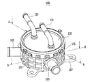
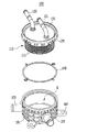
図2は、本発明の実施形態に係るカン型熱交換器の斜視図であり、図3はその分解斜視図である。
本発明の実施形態に係るカン型熱交換器100は、図2及び図3に示すように、ハウジング101、放熱ユニット110、及びカバーキャップ130を含んで構成される。
FIG. 2 is a perspective view of a can-type heat exchanger according to an embodiment of the present invention, and FIG. 3 is an exploded perspective view thereof.
As shown in FIGS. 2 and 3, the can-
ハウジング101は、一面が開口され、他面は閉鎖されて内部に空間Sが形成される。このようなハウジング101は、側面に空間Sと連通する第1流入口103と第1排出口105が形成される。
ここで、ハウジング101は、円筒形状に形成されるが、射出成形により製作されることができる。
The
Here, the
一方、ハウジング101は、円形又は多角形状に形成されてもよい。
このようなハウジング101は、その材質がプラスチック素材で形成される。
また、ハウジング101は、他面の周りに少なくとも一つの装着部107が一体に形成されることができる。
On the other hand, the
Such a
The
装着部107は、エンジンルーム内部にカン型熱交換器100を装着するためのものであり、本実施形態では、ハウジング101の外周面の周りに沿って3つが設定角度で離隔した位置に形成される。
The mounting
本実施形態では、装着部107がハウジング101の他面で外周面の周りに3つが設定角度で離隔して形成されることを一実施形態として説明しているが、本発明は、これに限定されず、装着部107の位置及び個数は任意に変更して適用することができる。
一方、第1流入口103及び第1排出口105それぞれは、ハウジング101の側面に沿って設定角度で離隔した位置に突出形成することができる。
In the present embodiment, it has been described as an embodiment that the mounting
On the other hand, each of the
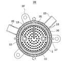
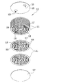
図4は、図2のA−A線に沿った断面図であり、図5は、図2のB−B線に沿った断面図であり、図6は、本発明の実施形態に係るカン型熱交換器に適用される放熱ユニットの分解斜視図であり、図7は、本発明の実施形態に係るカン型熱交換器に適用される放熱ユニットにおけるプレートの斜視図である。 4 is a cross-sectional view taken along line AA in FIG. 2, FIG. 5 is a cross-sectional view taken along line BB in FIG. 2, and FIG. 6 is a canal according to an embodiment of the present invention. FIG. 7 is an exploded perspective view of a heat radiating unit applied to the mold heat exchanger, and FIG. 7 is a perspective view of a plate in the heat radiating unit applied to the can type heat exchanger according to the embodiment of the present invention.
図4〜図7に示すように、本実施形態で、放熱ユニット110は、空間Sの内部に挿入され、複数個のプレート111が積層されて相互交互に連結流路113を形成する。
このような放熱ユニット110は、それぞれの連結流路113のうちのいずれか一つの連結流路113が空間Sと連結され、互いに異なる作動流体が各連結流路113を通過しながら相互に熱交換が行われる。
As shown in FIGS. 4 to 7, in this embodiment, the
In such a
そして、カバーキャップ130は、ハウジング101の開口された一面に装着され、空間Sに放熱ユニット110が一体に装着される。
このようなカバーキャップ130には、連結流路113のうちの他の一つの連結流路113と連結される第2流入口131と第2排出口133とがそれぞれ形成される。
The
The
ここで、カバーキャップ130は金属材質で形成され、放熱ユニット110がブレージング溶接によって一体に結合される。
即ち、放熱ユニット110は、カバーキャップ130がハウジング101に結合される前にカバーキャップ130に先ず組立てられる。
Here, the
That is, the
これにより、放熱ユニット110は、第2流入口131と第2排出口133に連結される他の一つの連結流路113から流入した作動流体の漏油を予め検査して、放熱ユニット110の作動不良が発生するのを防止できる。
As a result, the
一方、本実施形態で、第2流入口131と第2排出口133とは、カバーキャップ130の一面から離隔するように形成されることができる。
即ち、第2流入口131と第2排出口133は、第1流入口103及び第1排出口105と相互い交差した位置にそれぞれ形成することができる。
Meanwhile, in the present embodiment, the
That is, the
これにより、冷却水は、第1流入口103と第1排出口105を通じて空間Sと放熱ユニット110に循環し、変速機オイルは、第2流入口131と第2排出口133を通じて放熱ユニット110に循環することができる。
ここで、カバーキャップ130は、外周面にハウジング101に向かって一体に折曲されて形成される結合部135を更に含む。
Thereby, the cooling water circulates in the space S and the
Here, the
結合部135は、ハウジング101の外周面を取り囲んだ状態で、外周面の周りが少なくとも一つのクリンチング(Clinching)によって接合されることができる。
即ち、カバーキャップ130は、結合部135の外周面の周りが反復的にクリンチングされることにより、ハウジング101に堅固に結合される。
The
That is, the
本実施形態で、ハウジング101は、カバーキャップ130との間にシーリング140を介することができる。
シーリング140は、空間Sとカバーキャップ130との間をシールして、空間Sに流入した冷却水が外部に漏出するのを防止する。
In this embodiment, the
The sealing 140 seals between the space S and the
一方、本実施形態で、放熱ユニット110は、それぞれの連結流路113のいずれか一方の連結流路113が空間Sと連結され、第1、第2流入口103、131を通じて流入する冷却水と変速機オイルとが、各連結流路113を通過しながら相互に熱交換される。
On the other hand, in the present embodiment, the
即ち、放熱ユニット110は、変速機オイルが第2流入口131を通じて内部に流入して循環する場合、第1流入口103を通じてハウジング101の空間Sに流入する冷却水と互いに反対方向に流動し、その流動方向を対向流(counterflow)にして相互に熱交換させる。
That is, when the transmission oil flows into the inside through the
−
ここで、各連結流路113は、空間Sの内部に流入した冷却水が移動する第1連結流路113aと、変速機オイルが流入して移動する第2連結流路113bとを含む。
本実施形態で、プレート111は、ハウジング101の外形に対応して円板形状に形成されるが、第2流入口131と第2排出口133とに対応して第1、第2連結ホール115、117がそれぞれ形成される。
−
Here, each
In this embodiment, the
これにより、第2流入口131を通じて流入した変速機オイルは、第1連結ホール115を通じて放熱ユニット110の内部に流入して第2連結流路113bを通過した後、第2連結ホール117を通じて第2排出口133に排出される。
一方、図7に示したように、プレート111は、複数個の突起118が設定間隔で離隔して突出形成され、第1流入口103と第1排出口105の間に対応して中心から外周面まで分配突起119が形成されることができる。
Accordingly, the transmission oil that has flowed in through the
On the other hand, as shown in FIG. 7, the
各突起118は、半球形に形成され、分配突起119と同一の方向にプレート111の一面に突出形成され、プレート111の中心から外周面に向かって円周方向に沿って複数個が形成されることができる。
このように構成されるプレート111は、各突起118と分配突起119とが突出した一面が相互接触するように積層される。
Each
The
したがって、放熱ユニット110は、各突起118と分配突起119とが相互接触するように結合された二枚のプレート111を複数個積層して、第1連結流路113aと第2連結流路113bを交差するように形成することができる。
ここで、各突起118は、放熱ユニット110の第1連結流路113aを通過する冷却水と、第2連結流路113bを通過する変速機オイルに流動抵抗を発生させて、熱交換効率を増大させる。
Accordingly, the
Here, each
また、分配突起119は、第1、第2連結流路113a、113bを通過する変速機オイルと冷却水が流動する距離を増加させるように各作動流体の流動を分配して、各作動流体を放熱ユニット110のプレート111全領域に均等に流動させる。
このように構成される放熱ユニット110は、第1、第2固定プレート121、127を更に含む。
The
The
先ず、第1固定プレート121は、カバーキャップ130に固定される放熱ユニット110の一面に装着され、第1、第2連結ホール115、117に対応して第1、第2貫通ホール123、125が形成される。
そして第2固定プレート127は、空間Sに挿入される放熱ユニット110の他面に装着される。
ここで、第2固定プレート127は、放熱ユニット110の他面でプレート111に形成された第1、第2連結ホール115、117を閉鎖して、第1、第2連結ホール115、117を通じて流入した変速機オイルが外部に漏出するのを防止する。
First, the
The
Here, the second fixed
一方、本実施形態では、第1流入口103と第1排出口105を通じて流入及び排出される冷却水が、空間Sの内部で第1連結流路113aに流動し、第2流入口131を通じて流入した変速機オイルが、第2連結流路113bに流動するものを一実施形態に説明しているが、これに限定されず、冷却水と変速機オイルは互いに変更して適用することができる。
On the other hand, in this embodiment, the cooling water that flows in and out through the
以下、上記のように構成される本発明の実施形態に係るカン型熱交換器100の作動及び作用について詳細に説明する。
図8は、本発明の実施形態に係るカン型熱交換器の作動状態の斜視図である。
先ず、第1流入口103を通じて流入した冷却水は、図8に示したように、空間Sに流入して放熱ユニット110の外側と第1連結流路113aを通過した後、第1排出口105を通じて排出される。
Hereinafter, the operation and action of the can-
FIG. 8 is a perspective view of the operating state of the can-type heat exchanger according to the embodiment of the present invention.
First, the cooling water flowing in through the
このことにより、冷却水は、空間Sから第1連結流路113aを通過するようになり、第2流入口131を通じて流入して第2連結流路113bを通過する変速機オイルは、第1連結流路113aを通過する冷却水とハウジング101の空間Sで相互に熱交換が行われて、その温度が調節される。
As a result, the cooling water passes through the
ここで、変速機オイルは、自動変速機40から第2流入口131を通じて流入して空間Sで放熱ユニット110の第2連結流路113bを通過した後、第2排出口133を通じて排出されながら、冷却水と熱交換が行われる。
この場合、冷却水と変速機オイルとは、第1、第2流入口103、131がハウジング101の側面とカバーキャップ130の一面で相互に交差した方向に形成されることにより、各作動流体の流動方向を対向流にして相互に熱交換させ、これにより、更に効率的な熱交換が行われる。
Here, the transmission oil flows from the
In this case, the cooling water and the transmission oil are formed such that the first and
これにより、自動変速機40の内部で流体摩擦によって発熱して発生する冷却が必要な変速機オイルは、カン型熱交換器100の放熱ユニット110で冷却水との相互の熱交換によって冷却された状態で自動変速機40に供給される。
即ち、熱交換器100は、高速回転する自動変速機40に冷却した変速機オイルを供給することにより、自動変速機40のスリップ発生を防止する。
As a result, the transmission oil that needs to be cooled and is generated by heat generated by fluid friction within the
That is, the
このように、本発明の実施形態に係るカン型熱交換器100は、第1流入口103と第2流入口131を通じて流入する冷却水と変速機オイルとを相互に熱交換させて変速機オイルの温度を調節する。
一方、本発明の他の実施形態に係るカン型熱交換器200の構成について、添付した図10を参照して説明する。
As described above, the can-
Meanwhile, a configuration of a can-
図10は、本発明の他の実施形態に係るカン型熱交換器の斜視図である。
図10に示すように、本発明の他の実施形態に係るカン型熱交換器200は、ハウジング201、放熱ユニット210、及びカバーキャップ230を含む。
ここで、ハウジング201は第1流入口203と第1排出口205を含み、カバーキャップ230は第2流入口231と第2排出口233を含む。
FIG. 10 is a perspective view of a can-type heat exchanger according to another embodiment of the present invention.
As shown in FIG. 10, a can-
Here, the
カバーキャップ230は結合部235を含んで構成され、これは、前述した一実施形態と同一なので、以下、その詳細な説明は省略する。
このように構成される本発明の他の実施形態に係るカン型熱交換器200において、カバーキャップ230は他面に装着プレート250が装着され、装着プレート250の外周面には装着部251が一体に形成されることができる。
The
In the can-
これにより、本発明の他の実施形態に係るカン型熱交換器200は、装着プレート250を通じて自動変速機40の一側に直接装着されることができる。
即ち、本発明の他の実施形態に係るカン型熱交換器200は、カバーキャップ230に装着された装着プレート250の装着部251を通じて自動変速機40の一側に装着されることにより、変速機オイルの供給及び排出のための配管を除去することができる。
Accordingly, the can-
That is, the can-
したがって、上記のように構成される本発明の実施形態に係るカン型熱交換器100、200を適用すると、それぞれの作動流体が内部で流動しながら相互に熱交換するとき、熱交換効率を増大させると共に、重量及びサイズの縮小が可能なカン形状に形成することにより、狭いエンジンルーム内部でレイアウトを簡素化することができる。
また、エンジンルーム内部で装着空間の確保が容易で、搭載性及びパッケージ性を向上させることができる。
Therefore, when the can-
In addition, it is easy to secure a mounting space inside the engine room, and the mountability and packageability can be improved.
また、放熱ユニット110、210が一体に装着されたカバーキャップ130、230を、射出成形によって製作されたハウジング101、201に結合して製作を完了することにより、製作及び組立作業が容易になり、製作費用を節減し、かつ生産性を向上させることができる。
これと同時に、カバーキャップ130、230の組立前に放熱ユニット110、210の不良有無を確認できるので、完成品の不良発生を未然に防止し、商品性を向上させることができる。
Further, by combining the cover caps 130 and 230, to which the
At the same time, since the presence or absence of defects in the
以上、本発明は例え限定された実施形態及び図面によって説明されたとしても、本発明はこれによって限定されるものではなく、本発明が属する技術分野における通常の知識を有する者によって本発明の技術思想と特許請求の範囲の均等範囲内で多様な修正及び変形が可能であることは勿論である。 As mentioned above, even if the present invention has been described with reference to limited embodiments and drawings, the present invention is not limited thereto, and the technology of the present invention can be achieved by persons having ordinary knowledge in the technical field to which the present invention belongs. It goes without saying that various modifications and variations are possible within the scope of the idea and the scope of claims.
100 カン型熱交換器
101 ハウジング
103 第1流入口
105 第1排出口
107 装着部
110 放熱ユニット
111 プレート
113 連結流路
113a 第1連結流路
113b 第2連結流路
115 第1連結ホール
117 第2連結ホール
118 突起
119 分配突起
121 第1固定プレート
123 第1貫通ホール
125 第2貫通ホール
127 第2固定プレート
130 カバーキャップ
131 第2流入口
133 第2排出口
135 結合部
140 シーリング
DESCRIPTION OF
Claims (18)
一面が開口され、他面が閉鎖されて内部に空間が形成され、側面には前記空間と連通される第1流入口と第1排出口とが形成されたハウジングと、
前記空間の内部に挿入され、複数個のプレートが積層されて相互かつ交互に連結流路が形成され、それぞれの前記連結流路の何れか一つの連結流路が前記空間と連結されて、互いに異なる作動流体が前記各連結流路を通過しながら相互に熱交換が行われる放熱ユニットと、
前記空間に対応する一面に前記放熱ユニットが一体に装着され、前記連結流路のうち他の一つの連結流路と連結される第2流入口と第2排出口とがそれぞれ形成され、前記ハウジングの開口された一面に装着されるカバーキャップと、
を含むことを特徴とする、カン型熱交換器。 A can-shaped heat exchanger,
A housing in which one surface is opened, the other surface is closed to form a space therein, and a first inflow port and a first discharge port communicated with the space are formed on the side surface;
Inserted into the space, a plurality of plates are laminated to form a connection channel alternately and alternately, and any one of the connection channels is connected to the space, and A heat dissipating unit in which different working fluids exchange heat with each other while passing through each of the connection channels;
The heat radiating unit is integrally mounted on one surface corresponding to the space, and a second inflow port and a second discharge port connected to another one of the connection channels are formed, and the housing A cover cap to be attached to one side of the opening,
A can-type heat exchanger comprising:
該放熱ユニットの前記カバーキャップに固定される側の一面に装着され、前記第1、第2連結ホールに対応して第1、第2貫通ホールが形成される第1固定プレートと、
前記放熱ユニットの前記空間に挿入される側の他面に装着される第2固定プレートと、を更に含むことを特徴とする、請求項10に記載のカン型熱交換器。 The heat dissipation unit is
A first fixing plate mounted on one surface of the heat radiating unit fixed to the cover cap and having first and second through holes formed corresponding to the first and second connection holes;
The can-type heat exchanger according to claim 10, further comprising a second fixed plate mounted on the other surface of the heat radiating unit on the side inserted into the space.
ラジエータから流入する冷却水と、自動変速機から流入する変速機オイルと、で構成されることを特徴とする、請求項1に記載のカン型熱交換器。 Each working fluid is
The can-type heat exchanger according to claim 1, comprising cooling water flowing from a radiator and transmission oil flowing from an automatic transmission.
前記各連結流路は、冷却水が流入して移動する第1連結流路と、変速機オイルが流入して移動する第2連結流路と、を含むことを特徴とする、請求項14に記載のカン型熱交換器。 The cooling water circulates through the first inlet and the first outlet, and the transmission oil circulates through the second inlet and the second outlet to the heat dissipation unit,
15. Each of the connection channels includes a first connection channel in which cooling water flows and moves, and a second connection channel in which transmission oil flows and moves. The can-type heat exchanger described.
Applications Claiming Priority (2)
| Application Number | Priority Date | Filing Date | Title |
|---|---|---|---|
| KR1020150084260A KR20160147475A (en) | 2015-06-15 | 2015-06-15 | Can-type heat exchanger |
| KR10-2015-0084260 | 2015-06-15 |
Publications (1)
| Publication Number | Publication Date |
|---|---|
| JP2017003250A true JP2017003250A (en) | 2017-01-05 |
Family
ID=54770887
Family Applications (1)
| Application Number | Title | Priority Date | Filing Date |
|---|---|---|---|
| JP2015235610A Pending JP2017003250A (en) | 2015-06-15 | 2015-12-02 | Can-type heat exchanger |
Country Status (5)
| Country | Link |
|---|---|
| US (1) | US20160363391A1 (en) |
| EP (1) | EP3106818A1 (en) |
| JP (1) | JP2017003250A (en) |
| KR (1) | KR20160147475A (en) |
| CN (1) | CN106247817A (en) |
Cited By (2)
| Publication number | Priority date | Publication date | Assignee | Title |
|---|---|---|---|---|
| KR20170030633A (en) * | 2014-11-27 | 2017-03-17 | 파나소닉 아이피 매니지먼트 가부시키가이샤 | Gait analysis system and gait analysis program |
| KR20180058999A (en) * | 2016-11-25 | 2018-06-04 | 알바이오텍 주식회사 | System and method for gait analyzing and computer readable record medium thereof |
Families Citing this family (4)
| Publication number | Priority date | Publication date | Assignee | Title |
|---|---|---|---|---|
| DE102016100305A1 (en) * | 2016-01-11 | 2017-07-13 | Hanon Systems | Arrangement for intercooling |
| SI3800422T1 (en) * | 2017-03-10 | 2023-12-29 | Alfa Laval Corporate Ab | Plate for a heat exchanger device |
| KR101992026B1 (en) * | 2017-11-23 | 2019-06-21 | 고려대학교 산학협력단 | Shell and plate heat exchanger |
| US11668212B2 (en) * | 2018-06-20 | 2023-06-06 | Champion Power Equipment, Inc. | Double-sided oil cooler for use in a generator engine |
Family Cites Families (10)
| Publication number | Priority date | Publication date | Assignee | Title |
|---|---|---|---|---|
| US2222721A (en) * | 1936-04-13 | 1940-11-26 | Gen Motors Corp | Oil cooler |
| JPH10238969A (en) * | 1997-02-25 | 1998-09-11 | Toyo Radiator Co Ltd | Cold water heat-exchanger |
| US7004237B2 (en) * | 2001-06-29 | 2006-02-28 | Delaware Capital Formation, Inc. | Shell and plate heat exchanger |
| DE102004004895B3 (en) * | 2004-01-30 | 2005-06-16 | Pressko Ag | Heat exchanger comprises a plate packet delimited by a packet tension plate with openings having a diameter which is larger than the diameter of the plate packet |
| US20080202735A1 (en) * | 2005-07-19 | 2008-08-28 | Peter Geskes | Heat Exchanger |
| WO2007048603A2 (en) * | 2005-10-26 | 2007-05-03 | Behr Gmbh & Co. Kg | Heat exchanger, method for the production of a heat exchanger |
| DE102009047620C5 (en) * | 2009-12-08 | 2023-01-19 | Hanon Systems | Heat exchanger with tube bundle |
| FR2962199B1 (en) * | 2010-06-30 | 2012-09-21 | Valeo Systemes Thermiques | CONDENSER, IN PARTICULAR FOR AIR CONDITIONING SYSTEM OF A MOTOR VEHICLE. |
| KR101284183B1 (en) * | 2011-12-23 | 2013-07-09 | 최영종 | Disassemblable primary surface heat exchanger |
| FI124230B (en) * | 2012-05-28 | 2014-05-15 | Vahterus Oy | METHOD AND ORGANIZATION FOR REPAIRING THE HEAT EXCHANGER DISK PACK AND THE HEAT EXCHANGER |
-
2015
- 2015-06-15 KR KR1020150084260A patent/KR20160147475A/en not_active Application Discontinuation
- 2015-11-21 US US14/948,292 patent/US20160363391A1/en not_active Abandoned
- 2015-11-30 EP EP15197055.5A patent/EP3106818A1/en not_active Withdrawn
- 2015-12-02 JP JP2015235610A patent/JP2017003250A/en active Pending
- 2015-12-02 CN CN201510876146.7A patent/CN106247817A/en active Pending
Cited By (2)
| Publication number | Priority date | Publication date | Assignee | Title |
|---|---|---|---|---|
| KR20170030633A (en) * | 2014-11-27 | 2017-03-17 | 파나소닉 아이피 매니지먼트 가부시키가이샤 | Gait analysis system and gait analysis program |
| KR20180058999A (en) * | 2016-11-25 | 2018-06-04 | 알바이오텍 주식회사 | System and method for gait analyzing and computer readable record medium thereof |
Also Published As
| Publication number | Publication date |
|---|---|
| CN106247817A (en) | 2016-12-21 |
| KR20160147475A (en) | 2016-12-23 |
| EP3106818A1 (en) | 2016-12-21 |
| US20160363391A1 (en) | 2016-12-15 |
Similar Documents
| Publication | Publication Date | Title |
|---|---|---|
| JP2017003250A (en) | Can-type heat exchanger | |
| JP6211357B2 (en) | Vehicle heat exchanger | |
| JP6552810B2 (en) | Can type heat exchanger | |
| KR101339250B1 (en) | Heat exchanger for vehicle | |
| JP6317920B2 (en) | Vehicle heat exchanger | |
| KR101283591B1 (en) | Heat exchanger for vehicle | |
| KR101526427B1 (en) | Heat exchanger for vehicle | |
| KR101405186B1 (en) | Heat exchanger for vehicle | |
| JP6054627B2 (en) | Vehicle heat exchanger | |
| JP2013113578A (en) | Vehicle heat exchanger | |
| KR101703603B1 (en) | Can-type heat exchanger | |
| JP2012229906A (en) | Heat exchanger for vehicle | |
| KR20130063345A (en) | Heat exchanger for vehicle | |
| JP2013113579A (en) | Vehicle heat exchanger | |
| JP2001174096A (en) | Heat exchanger for temperature regulator | |
| WO2022143709A1 (en) | Control valve and thermal management assembly | |
| KR101274247B1 (en) | Heat exchanger for vehicle | |
| KR20190033929A (en) | Oil Cooler | |
| KR20160082887A (en) | Heat exchanger for vehicles | |
| CN205245623U (en) | Condenser | |
| EP4235075A1 (en) | Heat exchanger, heat exchange assembly, and heat management system | |
| KR20160025097A (en) | Heat exchager with flow passage changing plate for vehicle | |
| JP2017073421A (en) | Heat exchanger device of temperature adjusted component |