JP2017003049A - Centrifugal clutch - Google Patents
Centrifugal clutch Download PDFInfo
- Publication number
- JP2017003049A JP2017003049A JP2015119154A JP2015119154A JP2017003049A JP 2017003049 A JP2017003049 A JP 2017003049A JP 2015119154 A JP2015119154 A JP 2015119154A JP 2015119154 A JP2015119154 A JP 2015119154A JP 2017003049 A JP2017003049 A JP 2017003049A
- Authority
- JP
- Japan
- Prior art keywords
- drive plate
- clutch
- centrifugal clutch
- contact
- drive
- Prior art date
- Legal status (The legal status is an assumption and is not a legal conclusion. Google has not performed a legal analysis and makes no representation as to the accuracy of the status listed.)
- Granted
Links
Images


Classifications
-
- F—MECHANICAL ENGINEERING; LIGHTING; HEATING; WEAPONS; BLASTING
- F16—ENGINEERING ELEMENTS AND UNITS; GENERAL MEASURES FOR PRODUCING AND MAINTAINING EFFECTIVE FUNCTIONING OF MACHINES OR INSTALLATIONS; THERMAL INSULATION IN GENERAL
- F16D—COUPLINGS FOR TRANSMITTING ROTATION; CLUTCHES; BRAKES
- F16D43/00—Automatic clutches
- F16D43/02—Automatic clutches actuated entirely mechanically
- F16D43/04—Automatic clutches actuated entirely mechanically controlled by angular speed
- F16D43/14—Automatic clutches actuated entirely mechanically controlled by angular speed with centrifugal masses actuating the clutching members directly in a direction which has at least a radial component; with centrifugal masses themselves being the clutching members
- F16D43/18—Automatic clutches actuated entirely mechanically controlled by angular speed with centrifugal masses actuating the clutching members directly in a direction which has at least a radial component; with centrifugal masses themselves being the clutching members with friction clutching members
-
- F—MECHANICAL ENGINEERING; LIGHTING; HEATING; WEAPONS; BLASTING
- F16—ENGINEERING ELEMENTS AND UNITS; GENERAL MEASURES FOR PRODUCING AND MAINTAINING EFFECTIVE FUNCTIONING OF MACHINES OR INSTALLATIONS; THERMAL INSULATION IN GENERAL
- F16D—COUPLINGS FOR TRANSMITTING ROTATION; CLUTCHES; BRAKES
- F16D43/00—Automatic clutches
- F16D43/02—Automatic clutches actuated entirely mechanically
- F16D43/04—Automatic clutches actuated entirely mechanically controlled by angular speed
- F16D43/14—Automatic clutches actuated entirely mechanically controlled by angular speed with centrifugal masses actuating the clutching members directly in a direction which has at least a radial component; with centrifugal masses themselves being the clutching members
- F16D2043/145—Automatic clutches actuated entirely mechanically controlled by angular speed with centrifugal masses actuating the clutching members directly in a direction which has at least a radial component; with centrifugal masses themselves being the clutching members the centrifugal masses being pivoting
Landscapes
- Engineering & Computer Science (AREA)
- General Engineering & Computer Science (AREA)
- Mechanical Engineering (AREA)
- One-Way And Automatic Clutches, And Combinations Of Different Clutches (AREA)
Abstract
Description
エンジンが所定の回転数に達するまでの間は回転駆動力の従動側への伝達を遮断するとともに、エンジンが所定の回転数に達したときに回転駆動力を従動側に伝達する遠心クラッチに関する。 The present invention relates to a centrifugal clutch that blocks transmission of rotational driving force to the driven side until the engine reaches a predetermined rotational speed and transmits rotational driving force to the driven side when the engine reaches a predetermined rotational speed.
従来から、二輪自動車や刈払機などにおいては、エンジンが所定の回転数に達したときに回転駆動力を従動側に伝達する遠心クラッチが用いられている。例えば、下記特許文献1には、エンジンの回転数の増加に伴って徐々にクラッチウエイトがクラッチアウター側に変位して摩擦接触する遠心クラッチが開示されている。また、下記特許文献2には、エンジンの駆動力によって回転駆動するカム状突起に円柱状の転子が乗り上げることによって転子の外側に設けられたクラッチシューをクラッチアウター押圧してクラッチを連結状態とする遠心クラッチが開示されている。 2. Description of the Related Art Conventionally, a two-wheeled vehicle, a brush cutter, or the like uses a centrifugal clutch that transmits a rotational driving force to a driven side when an engine reaches a predetermined rotational speed. For example, Patent Document 1 below discloses a centrifugal clutch in which a clutch weight is gradually displaced toward the clutch outer side and frictionally contacts with an increase in the engine speed. Further, in Patent Document 2 below, when a cylindrical trochanter rides on a cam-like projection that is rotationally driven by the driving force of an engine, a clutch shoe provided on the outer side of the trochanter is pressed outward from the clutch, and the clutch is connected. A centrifugal clutch is disclosed.
しかしながら、上記特許文献1に記載された遠心クラッチにおいては、エンジンの回転数の増加に応じて徐々にクラッチウエイトがクラッチアウターに摩擦接触するため、エンジンの回転数が増加し始めてからクラッチが連結状態となるまでの時間が長く燃費を低下させるという問題がある。一方、上記特許文献2に記載された遠心クラッチにおいては、カム状突起の回転の直後に転子がカム状突起上に乗り上げてクラッチが連結状態となるため、従動側が急作動して操作者には扱い難いという問題があった。 However, in the centrifugal clutch described in Patent Document 1, since the clutch weight gradually comes into frictional contact with the outer clutch as the engine speed increases, the clutch is engaged after the engine speed starts increasing. There is a problem that the fuel consumption is lowered for a long time. On the other hand, in the centrifugal clutch described in Patent Document 2, the trochanter rides on the cam-like protrusion immediately after the rotation of the cam-like protrusion and the clutch is in a connected state. There was a problem that it was difficult to handle.
本発明は上記問題に対処するためなされたもので、その目的は、従動側の急激な始動を抑えつつ迅速に連結状態とすることができる遠心クラッチを提供することにある。 The present invention has been made to cope with the above problems, and an object of the present invention is to provide a centrifugal clutch that can be quickly connected while suppressing a sudden start on the driven side.
上記目的を達成するため、本発明の特徴は、エンジンの駆動力を受けてドリブンプーリとともに一体的に回転駆動する第1ドライブプレートと、第1ドライブプレートの外側に配置されて同第1ドライブプレートに対して相対的な回転変位を許容しつつ一体的に回転駆動可能な摩擦力で接触するリング状の第2ドライブプレートと、第2ドライブプレート上に可動的に取り付けられて第2ドライブプレートの回転駆動による遠心力によって第2ドライブプレートの外側に向かって変位するとともに同外側の面にクラッチシューを有したクラッチウエイトと、第2ドライブプレートの外側に向かって変位したクラッチシューに摩擦接触する円筒面を有したクラッチアウターと、第1ドライブプレートの外側に向かって傾斜して延びる第1傾斜面を有して同第1ドライブプレートに設けられたカム体と、第1傾斜面に面接触する第2傾斜面を有してクラッチウエイトに設けられた従動部とを備え、第1ドライブプレートは、第1ドライブプレートから張り出して形成されて第2ドライブプレートに対向する支持部を有し、カム体は、第1ドライブプレートから張り出して形成された支持部に保持ピンを介して第1ドライブプレートの回転動方向に回動自在に支持されていることにある。 In order to achieve the above object, the present invention is characterized in that a first drive plate that rotates together with a driven pulley under the driving force of an engine, and a first drive plate that is disposed outside the first drive plate. A ring-shaped second drive plate that makes contact with a frictional force that can be rotationally driven integrally while allowing relative rotational displacement, and a second drive plate that is movably mounted on the second drive plate. A cylinder weight that displaces toward the outside of the second drive plate by a centrifugal force due to rotational drive and has a clutch shoe on the outside surface, and a cylinder that frictionally contacts the clutch shoe displaced toward the outside of the second drive plate. Clutch outer having a surface and a first inclined surface extending inclined toward the outside of the first drive plate And a cam body provided on the first drive plate and a driven portion provided on the clutch weight having a second inclined surface in surface contact with the first inclined surface. The cam body has a support portion that extends from the first drive plate and faces the second drive plate, and the cam body is attached to the support portion that extends from the first drive plate via a holding pin. It is supported so as to be rotatable in the rotational direction.
このように構成した本発明の特徴によれば、遠心クラッチは、第1ドライブプレートが回転駆動を開始した後、クラッチシューがクラッチアウターに接触することで第2ドライブプレートが第1ドライブプレートに対して回転駆動方向の後方側にずれる際、従動部がカム体上を乗り上げることによってクラッチシューがクラッチアウターを急速に押圧する。すなわち、遠心クラッチは、第1ドライブプレートが回転駆動を開始してから連結状態となるまでの間にクラッチシューがクラッチアウターに接触するまでの時間が確保されるとともに、クラッチシューがクラッチアウターに接触した際には急速に連結状態に移行する。これにより、遠心クラッチは、従動側の急激な始動を抑えつつ迅速に連結状態にすることができる。 According to the feature of the present invention configured as described above, the centrifugal clutch is configured such that after the first drive plate starts to rotate, the second shoe plate comes into contact with the first drive plate by the clutch shoe coming into contact with the outer clutch member. Therefore, when the driven part moves over the cam body, the clutch shoe rapidly presses the clutch outer. That is, the centrifugal clutch secures time until the clutch shoe comes into contact with the outer clutch during the period from when the first drive plate starts to rotate until it is connected, and the clutch shoe comes into contact with the outer clutch. When it does, it will shift to a connected state rapidly. Thereby, the centrifugal clutch can be quickly brought into a connected state while suppressing a rapid start on the driven side.
また、本発明に係る遠心クラッチにおいては、従動部がカム体上を乗り上げることによってクラッチシューをクラッチアウターに強圧させるため、エンジンからの回転駆動力を従来の遠心クラッチと同じ回転数であっても従来の遠心クラッチよりも軽量なクラッチウエイトで伝達することができる。すなわち、本発明に係る遠心クラッチによれば、クラッチウエイトを軽量化することができるため、クラッチの連結時におけるジャダーの発生を抑制することができるとともに遠心クラッチの構成の簡単化、コンパクト化および低コスト化することができる。そして、このことは、従来の遠心クラッチに対してクラッチウエイトの重量を同じとすれば、遠心クラッチが伝達できる駆動力を増大させることができることを意味するものである。また、本発明に係る遠心クラッチにおいては、第1ドライブプレートと第2ドライブプレートとの接触面における摩擦力の大きさを調節することによってクラッチが連結状態となるまでの時間を適宜調節することもできる。 Further, in the centrifugal clutch according to the present invention, the driven shoe rides on the cam body to strongly press the clutch shoe against the clutch outer, so that the rotational driving force from the engine has the same rotational speed as that of the conventional centrifugal clutch. Transmission is possible with a clutch weight that is lighter than conventional centrifugal clutches. That is, according to the centrifugal clutch according to the present invention, the weight of the clutch can be reduced, so that the generation of judder when the clutch is engaged can be suppressed, and the configuration of the centrifugal clutch can be simplified, made compact, and reduced. Cost can be increased. This means that the driving force that can be transmitted by the centrifugal clutch can be increased if the weight of the clutch weight is the same as that of the conventional centrifugal clutch. In the centrifugal clutch according to the present invention, it is possible to appropriately adjust the time until the clutch is engaged by adjusting the magnitude of the frictional force on the contact surface between the first drive plate and the second drive plate. it can.
また、本発明によれば、遠心クラッチは、カム体が第1ドライブプレートの回転駆動方向に回動自在に設けられているため、クラッチアウターに摩擦接触するクラッチシューに摩耗が生じた場合であってもカム体が回転方向後方側に回動することによって従動部に対する面接触を維持することができ、長期間に亘って安定的にクラッチシューをクラッチアウターに向かって押圧することができる。また、本発明に係る遠心クラッチは、クラッチシューの摩耗に従ってカム体の回動角が大きくなって第1傾斜面が接線方向に近づくため、クラッチシューのクラッチアウターへの押圧力が増加する。これにより、遠心クラッチは、クラッチシューの摩擦面が平滑化した場合であってもクラッチシューのクラッチアウターへの押圧力の増加によって摩擦力の低下を抑えることができる。また、本発明に係る遠心クラッチは、カム体が保持ピンによって支持されているため、第1ドライブプレートに対して精度良く回転自在に保持することができるとともに、カム体や保持ピンの交換などのメンテナンスを行い易くすることができる。 In addition, according to the present invention, the centrifugal clutch is a case where the cam body is provided so as to be rotatable in the rotational drive direction of the first drive plate, so that wear occurs in the clutch shoe that frictionally contacts the clutch outer. Even in this case, the cam body is rotated rearward in the rotational direction, so that the surface contact with the driven portion can be maintained, and the clutch shoe can be stably pressed toward the outer clutch for a long period of time. Further, in the centrifugal clutch according to the present invention, the rotation angle of the cam body increases as the clutch shoe wears, and the first inclined surface approaches the tangential direction, so that the pressing force of the clutch shoe to the clutch outer increases. Thereby, even if the friction surface of a clutch shoe is smooth | blunted, the centrifugal clutch can suppress the fall of frictional force by the increase in the pressing force to the clutch outer of a clutch shoe. In addition, since the cam body is supported by the holding pin, the centrifugal clutch according to the present invention can be held rotatably with high precision with respect to the first drive plate, and the cam body and the holding pin can be exchanged. Maintenance can be facilitated.
また、本発明の他の特徴は、前記遠心クラッチにおいて、保持ピンは、第1ドライブプレートに形成された支持部に回動自在に嵌合してカム体を支持する軸部およびこの軸部の一端に設けられて第2ドライブプレートに接触する面状の接触部をそれぞれ有するとともに、接触部が第2ドライブプレート上を転動するように面状に形成された接触部の一部のみが第2ドライブプレートに接触していることにある。 According to another aspect of the present invention, in the centrifugal clutch, the holding pin is rotatably fitted to a support portion formed on the first drive plate to support the cam body and the shaft portion. Each has a planar contact portion that is provided at one end and contacts the second drive plate, and only a part of the contact portion formed in a planar shape so that the contact portion rolls on the second drive plate is the first. 2 is in contact with the drive plate.
このように構成した本発明の他の特徴によれば、遠心クラッチは、保持ピンにおいて接触部が面状に形成されるとともに、この面状に形成された接触部の一部のみが前記第2ドライブプレートに接触しているため、この保持ピンを第2ドライブプレート上に対して転動させることができ、第2ドライブプレートが第1ドライブプレートに対して相対回転した際における両者の摩擦を低減して両者間における焼き付き、だき付き(焼き付きの前段階における摩擦抵抗の上昇)またはフレッティング(異常摩耗)を抑制することができる。 According to another feature of the present invention configured as described above, the centrifugal clutch has a contact portion formed in a planar shape in the holding pin, and only a part of the contact portion formed in the planar shape is the second portion. Since it is in contact with the drive plate, the holding pin can roll on the second drive plate, reducing friction between the two when the second drive plate rotates relative to the first drive plate. Thus, seizure, sticking (increased frictional resistance in the previous stage of seizure) or fretting (abnormal wear) between the two can be suppressed.
また、本発明の他の特徴は、前記遠心クラッチにおいて、第1ドライブプレートは、支持部が第2ドライブプレートに対して傾斜して形成されていることにある。 Another feature of the present invention is that, in the centrifugal clutch, the first drive plate is formed such that a support portion is inclined with respect to the second drive plate.
このように構成した本発明の他の特徴によれば、遠心クラッチは、保持ピンを第2ドライブプレートに対して傾斜させることができ、簡単に接触部の一部のみを第2ドライブプレートに接触させることができる。 According to another aspect of the present invention configured as described above, the centrifugal clutch can incline the holding pin with respect to the second drive plate, and easily contacts only a part of the contact portion with the second drive plate. Can be made.
遠心クラッチは、第1ドライブプレートの支持部を傾斜させることに代えて、または加えて、接触部を軸部に対して傾斜して形成する、接触部自体を傾斜面に形成(例えば、厚さを変化させる)する、保持ピンの軸部が嵌合する支持部の孔部を傾斜した状態で形成する、または接触部が転動する第2ドライブプレートの転動面を傾斜して形成して構成することができる。 In the centrifugal clutch, instead of or in addition to inclining the support portion of the first drive plate, the contact portion is formed to be inclined with respect to the shaft portion. Or by forming the hole part of the support part into which the shaft part of the holding pin fits in an inclined state, or inclining the rolling surface of the second drive plate on which the contact part rolls. Can be configured.
また、本発明の他の特徴は、前記遠心クラッチにおいて、第1ドライブプレートは、少なくとも支持部が熱処理されることによって第2ドライブプレートに対して傾斜して形成されていることにある。 According to another aspect of the present invention, in the centrifugal clutch, the first drive plate is formed to be inclined with respect to the second drive plate by heat-treating at least the support portion.
このように構成した本発明の他の特徴によれば、遠心クラッチは、支持部が熱処理されており、この熱処理によって第2ドライブプレートに対して傾斜して形成されるため、支持部を傾斜させるための加工が不要となり、製造工程を簡易化することができる。なお、この場合、支持部への熱処理としては、支持部の内部まで硬化させる通常の焼入れ処理(全体焼入れ、部分焼入れを含む)のほか、表面硬化処理(浸炭焼入れ、高周波焼入れ、火炎焼入れ、窒化処理、レーザ焼入れなど)がある。 According to another feature of the present invention configured as described above, the centrifugal clutch has the support portion heat-treated, and is inclined with respect to the second drive plate by this heat treatment, so that the support portion is inclined. Therefore, the manufacturing process can be simplified. In this case, as the heat treatment to the support part, in addition to the normal quenching process (including whole quenching and partial quenching) for curing to the inside of the support part, surface hardening process (carburizing quenching, induction quenching, flame quenching, nitriding) Treatment, laser quenching, etc.).
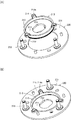
以下、本発明に係る遠心クラッチの一実施形態について図面を参照しながら説明する。図1は、本発明に係る遠心クラッチ200を備えた動力伝達機構100の構成を概略的に示す平面断面図である。また、図2は、図1に示す2−2線から見た遠心クラッチ200の側面図である。この遠心クラッチ200を備えた動力伝達機構100は、主としてスクータなどの自動二輪車両において、エンジンと駆動輪である後輪との間に設けられてエンジンの回転数に対する減速比を自動的に変更しながら回転駆動力を後輪に伝達または遮断する機械装置である。
Hereinafter, an embodiment of a centrifugal clutch according to the present invention will be described with reference to the drawings. FIG. 1 is a plan sectional view schematically showing a configuration of a
(遠心クラッチ200の構成)
この動力伝達機構100は、主として、変速機101および遠心クラッチ200をそれぞれ備えている。変速機101は、図示しないエンジンからの回転駆動力を無段階で減速して遠心クラッチ200に伝達する機械装置であり、主として、ドライブプーリ110、Vベルト120およびドリブンプーリ130をそれぞれ備えて構成されている。これらのうち、ドライブプーリ110は、エンジンから延びるクランク軸111上に設けられてエンジンの回転駆動力によって直接回転駆動する機械装置であり、主として、固定ドライブプレート112および可動ドライブプレート113をそれぞれ備えて構成されている。
(Configuration of centrifugal clutch 200)
The
固定ドライブプレート112は、可動ドライブプレート113とともにVベルト120を挟んで保持した状態で回転駆動する部品であり、金属材を円錐筒状に形成して構成されている。この固定ドライブプレート112は、凸側の面が可動ドライブプレート113側(エンジン側)に向いた状態でクランク軸111上に固定的に取り付けられている。すなわち、固定ドライブプレート112は、常にクランク軸111と一体的に回転駆動する。また、固定ドライブプレート112における凹側の面上には、複数の放熱フィン112aが放射状に設けられている。
The fixed
可動ドライブプレート113は、固定ドライブプレート112とともにVベルト120を挟んで保持した状態で回転駆動する部品であり、金属材を円錐筒状に形成して構成されている。この可動ドライブプレート113は、凸側の面が固定ドライブプレート112に対向する向きでクランク軸111に取り付けられている。この場合、可動ドライブプレート113は、クランク軸111に対して固定的に嵌合するスリーブ軸受114上に含浸ブッシュを介して取り付けられており、スリーブ軸受114に対して軸方向および周方向にそれぞれ摺動自在に取り付けられている。
The
一方、可動ドライブプレート113の凹側の面には、複数のローラウエイト115がランププレート116によって押圧された状態で設けられている。ローラウエイト115は、可動ドライブプレート113の回転数の増加に応じて径方向外側に変位することによってランププレート116と協働して可動ドライブプレート113を固定ドライブプレート112側に押圧するための部品であり、金属材を筒状に形成して構成されている。また、ランププレート116は、ローラウエイト115を可動ドライブプレート113側に押圧する部品であり、金属板を可動ドライブプレート113側に屈曲させて構成されている。
On the other hand, a plurality of
Vベルト120は、ドライブプーリ110の回転駆動力をドリブンプーリ130に伝達するための部品であり、芯線を樹脂材で覆った無端のリング状に形成されている。このVベルト120は、固定ドライブプレート112と可動ドライブプレート113との間およびドリブンプーリ130における固定ドリブンプレート131と可動ドリブンプレート134との間に配置されてドライブプーリ110とドリブンプーリ130との間に架設されている。
The V-
ドリブンプーリ130は、ドライブプーリ110およびVベルト120をそれぞれ介して伝達されるエンジンからの回転駆動力によって回転駆動する機械装置であり、主として、固定ドリブンプレート131および可動ドリブンプレート134をそれぞれ備えて構成されている。
The driven
固定ドリブンプレート131は、可動ドリブンプレート134とともにVベルト120を挟んで保持した状態で回転駆動する部品であり、金属材を円錐筒状に形成して構成されている。この固定ドリブンプレート131は、凸側の面が可動ドリブンプレート134側に向いた状態でドリブンスリーブ132上に固定的に取り付けられている。
The fixed driven
ドリブンスリーブ132は、固定ドリブンプレート131と一体的に回転駆動する金属製の筒状部品であり、ドライブシャフト133に対してベアリングを介して相対回転自在に取り付けられている。ドライブシャフト133は、この動力伝達機構100が搭載される自動二輪車両の後輪を図示しないトランスミッションを介して駆動するための金属製の回転軸体である。この場合、自動二輪車両の後輪は、ドライブシャフト133における一方(図示右側)の端部に取り付けられている。
The driven
可動ドリブンプレート134は、固定ドリブンプレート131とともにVベルト120を挟んで保持した状態で回転駆動する部品であり、金属材を円錐筒状に形成して構成されている。この可動ドリブンプレート134は、凸側の面が固定ドリブンプレート131に対向する向きでドリブンスリーブ132に対して軸方向に摺動自在な状態で嵌合している。
The movable driven
一方、可動ドリブンプレート134の凹側の面には、遠心クラッチ200における第1ドライブプレート210との間にトルクスプリング135が設けられている。トルクスプリング135は、可動ドリブンプレート134を固定ドリブンプレート131側に弾性的に押圧するコイルスプリングである。すなわち、この変速機101は、固定ドライブプレート112と可動ドライブプレート113との間隔で規定されるVベルト120を挟む直径と、固定ドリブンプレート131と可動ドリブンプレート134との間隔で規定されるVベルト120を挟む直径との大小関係によってエンジンの回転数を無段階で変速する。そして、ドリブンスリーブ132およびドライブシャフト133における各先端部側には遠心クラッチ200が設けられている。
On the other hand, a
遠心クラッチ200は、変速機101を介して伝達されたエンジンの回転駆動力をドライブシャフト133に伝達または遮断する機械装置であり、主として、第1ドライブプレート210、第2ドライブプレート230、クラッチウエイト240およびクラッチアウター250をそれぞれ備えて構成されている。
第1ドライブプレート210は、ドリブンスリーブ132と一体的に回転駆動する部品であり、金属材を有底筒状に形成して構成されている。より具体的には、第1ドライブプレート210は、図3(A),(B)にそれぞれ示すように、平板状の底部211の中央部にドリブンスリーブ132が貫通する貫通孔212が形成されているとともに、底部211の周囲に起立した筒部213の先端部に周方向に沿って等間隔に3つの支持部214がそれぞれ設けられている。
The
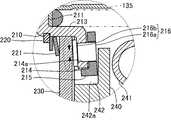
支持部214は、第2ドライブプレート230の表面に後述する保持ピン216を介して押し付けられるとともにカム体215を支持する部分であり、筒部213の先端部から径方向外側に片状に張り出して形成されている。すなわち、支持部214は、第2ドライブプレート230に対して対向した状態で設けられている。この場合、支持部214は、図4に示すように、耐摩耗性を向上させるために熱処理(焼入れ処理)が施されており、この焼入れ処理によって対向する第2ドライブプレート230の表面に対して傾斜した非平行な状態で形成されている。これにより、支持部214は、保持ピン216の接触部216bの一部のみを第2ドライブプレート230の表面に接触させる。また、この支持部214には、貫通孔214aが形成されており、この貫通孔214aにカム体215を貫通した状態で保持ピン216が摺動自在な状態で嵌合している。
The
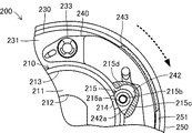
カム体215は、後述するクラッチウエイト240をクラッチアウター250側に押圧するための部品であり、金属材(例えば、炭素鋼や鉄系焼結材など)を板状に形成して構成されている。より具体的には、カム体215は、図5(A)〜(D)にそれぞれ示すように、板状に形成されたベース部215aの中央部に保持ピン216が貫通する貫通孔215bが形成されるとともに、このベース部215aの外周部の一部が直交する方向に張り出して肉厚が増した部分に第1傾斜面215cおよび円弧面215dがそれぞれ形成されている。この場合、貫通孔215bは、保持ピン216に対して摺動可能な内径、すなわち、保持ピン216に対して所謂隙間ばめとなる寸法公差で形成されている。
The
第1傾斜面215cは、クラッチウエイト240における第2傾斜面242aを面接触させた状態で摺動させる平坦な面であり、第1ドライブプレート210の回転駆動方向の後方でかつ同第1ドライブプレート210の外側に向かって傾斜して延びて形成されている。また、円弧面215dは、第1傾斜面215cの後端部から円弧状に延びて形成されている。なお、第1傾斜面215cおよび円弧面215dは、ベース部215aの板厚よりも張り出させて肉厚に形成されているが、これはカム体215を支持部214に容易かつ正確に組み付けるためのものである。したがって、第1傾斜面215cおよび円弧面215dは、ベース部215aの板厚と同じ肉厚で形成することもできる。
The first
保持ピン216は、カム体215を支持部214上に回転自在な状態で取り付けるための金属製の棒状部材であり、主として、軸部216aと接触部216bとで構成されている。軸部216aは、支持部214の貫通孔214aおよびカム体215の貫通孔215bに摺動自在に貫通する丸棒状の部分である。また、接触部216bは、第2ドライブプレート230に転がり接触する部分であり、軸部216aにおける一方の端部から張り出す円板状に形成されている。この保持ピン216は、カム体215の第1傾斜面215cが第1ドライブプレート210の回転駆動方向の後方でかつ同第1ドライブプレート210の外側に向かって傾斜して延びる向きで支持部214上に配置された状態でカム体215および支持部214を貫通している。
The holding
そして、この第1ドライブプレート210は、筒部213の先端部が第2ドライブプレート230の貫通孔232内に回転摺動可能に嵌合している。この場合、第1ドライブプレート210の筒部213の外周部には、平板リング状のクリップ220が嵌め込まれており、このクリップ220と第2ドライブプレート230との間に皿バネ221が嵌め込まれている。皿バネ221は、第1ドライブプレート210における支持部214と第2ドライブプレート230とを互いに押し付け合って摩擦接触させるための弾性体であり、平板リング状のバネ鋼を錘状に形成して構成されている。
In the
第2ドライブプレート230は、第1ドライブプレート210に対して相対的な回転変位が許容されつつ一体的に回転駆動する部品であり、金属材を平板リング状に形成して構成されている。より具体的には、第2ドライブプレート230は、板状のリング板231の中央部に第1ドライブプレート210の筒部213が摺動可能に嵌合する貫通孔232が形成されているとともに、リング板231上に周方向に沿って等間隔に3つの支点ピン233が起立した状態でそれぞれ設けられている。この場合、前記保持ピン216の接触部216bは、貫通孔232に隣接する縁部の平板部分を転動する。支点ピン233は、クラッチウエイト240を回動可能に支持するための部品であり、金属製の棒体で構成されている。
The
クラッチウエイト240は、第2ドライブプレート230の回転数に応じてクラッチアウター250に対してクラッチシュー243を介して接触または離隔することによってエンジンからの回転駆動力をドライブシャフト133に伝達または遮断するための部品であり、金属材(例えば、亜鉛材)を第2ドライブプレート230の周方向に沿って延びる湾曲した形状に形成して構成されている。このクラッチウエイト240は、一方の端部側が支点ピン233によって回動自在に支持された状態で、3つのクラッチウエイト240における互いに隣接するクラッチウエイト240同士が連結スプリング241によって互いに連結されて第2ドライブプレート230の内側方向に向かって回動するように引っ張られている。なお、図2においては、クラッチウエイト240の構成を分かり易くするため、3つのクラッチウエイト240のうちの2つのクラッチウエイト240の一部をそれぞれ異なる厚さ方向の面で破断して示している。
The
各クラッチウエイト240の内周面における前記第1ドライブプレート210のカム体215に対向する部分、より具体的には、連結スプリング241の下方の面(図示奥側の面)の裏面には、従動部242が凹状に窪んでそれぞれ形成されている。従動部242は、カム体215と協働してクラッチウエイト240をクラッチアウター250側に変位させるための部分であり、第1傾斜面215cと同様に平坦な傾斜面である第2傾斜面242aを有して構成されている。この従動部242は、第2傾斜面242aの厚さが第1傾斜面215cの肉厚より幅広に形成されるとともに、第2傾斜面242aが第1傾斜面215cに面接触した状態となっている。また、この従動部242は、第2傾斜面242aが第1傾斜面215cを構成するカム体215よりも摩耗し易い材料で構成されている。本実施形態においては、従動部242は、クラッチウエイト240と同じ金属材(例えば、亜鉛材)で構成されている。また、従動部242は、第2傾斜面242aより奥に入り込んだ部分が円弧状に切り欠かれており、カム体215の回動のためのスペースが確保されている。
The portion of the inner peripheral surface of each
一方、各クラッチウエイト240の外周面には、クラッチシュー243がそれぞれ設けられている。クラッチシュー243は、クラッチアウター250の内周面に対する摩擦力を増大させるための部品であり、摩擦材を円弧状に延びる板状に形成して構成されている。
On the other hand,
クラッチアウター250は、ドライブシャフト133と一体的に回転駆動する部品であり、金属材を第1ドライブプレート210からクラッチウエイト240の外周面を覆うカップ状に形成して構成されている。すなわち、クラッチアウター250は、第2ドライブプレート230の外周側に変位したクラッチウエイト240のクラッチシュー243に摩擦接触する円筒面251を有して構成されている。
The clutch outer 250 is a component that is rotationally driven integrally with the
(遠心クラッチ200の作動)
次に、上記のように構成した遠心クラッチ200の作動について説明する。この遠心クラッチ200は、自動二輪車車両(例えば、スクータ)におけるエンジンと駆動輪となる後輪との間に配置された動力伝達機構100の一部を構成して機能する。まず、遠心クラッチ200は、エンジンがアイドリング状態においては、図6に示すように、エンジンとドライブシャフト133との間の駆動力の伝達を遮断する。具体的には、遠心クラッチ200は、変速機101を介して伝達されるエンジンの回転駆動力によって第1ドライブプレート210とこの第1ドライブプレート210に対して皿バネ221を介して摩擦接触する第2ドライブプレート230とが一体的に回転駆動してクラッチウエイト240が回転駆動する。なお、図6においては、カム体215と従動部242との接触状態を明確にするため、連結スプリング241を省略している。
(Operation of centrifugal clutch 200)
Next, the operation of the
しかし、この場合、遠心クラッチ200は、クラッチウエイト240に作用する遠心力が連結スプリング241の弾性力(引張力)よりも小さいため、クラッチシュー243がクラッチアウター250の円筒面251に接触せずエンジンの回転駆動力がドライブシャフト133に伝達されることはない。なお、この場合、カム体215および従動部242は、第2傾斜面242aが連結スプリング241の弾性力(引張力)によって第1傾斜面215cに押し付けられて面接触した状態を維持している。
However, in this case, the
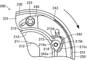
一方、遠心クラッチ200は、自動二輪車両における運転者のアクセル操作によるエンジンの回転数の増加に応じてエンジンの回転駆動力をドライブシャフト133に伝達する。具体的には、遠心クラッチ200は、図7に示すように、エンジンの回転数が増加するに従ってクラッチウエイト240に作用する遠心力が連結スプリング241の弾性力(引張力)よりも大きくなってクラッチウエイト240が支点ピン233を中心として径方向外側に向かって回動変位する。すなわち、遠心クラッチ200は、エンジンの回転数が増加するに従ってクラッチウエイト240が連結スプリング241の弾性力(引張力)に抗しながらクラッチアウター250の円筒面251側に回動変位する結果、クラッチシュー243が円筒面251に接触する。なお、図7においては、カム体215と従動部242との接触状態を明確にするため、連結スプリング241を省略している。また、図2および図7においては、遠心クラッチ200の回転駆動方向をそれぞれ破線矢印で示している。
On the other hand, the
このクラッチシュー243が円筒面251に接触した場合、クラッチウエイト240は、クラッチシュー243を介して回転駆動方向とは反対方向の反力を受ける。この場合、第1ドライブプレート210と第2ドライブプレート230とは、皿バネ221による弾性力(押圧力)によって摩擦接触しているが、クラッチウエイト240が受ける前記反力が摩擦接触する力を上回ると第2ドライブプレート230は第1ドライブプレート210の回転駆動方向とは反対方向に相対変位する。これにより、第2ドライブプレート230に支持されたクラッチウエイト240が第1ドライブプレート210の回転駆動方向とは反対方向に相対変位するため、カム体215の第1傾斜面215cに面接触する従動部242の第2傾斜面242aが第1傾斜面215cに沿って変位する。
When the
この場合、カム体215の第1傾斜面215cは、第1ドライブプレート210の回転駆動方向の後方でかつ同第1ドライブプレート210の外側に向かって傾斜して延びて形成されている。また、従動部242の第2傾斜面242aは、第1傾斜面215cと同じ平面に形成されて第1傾斜面215cに対して面接触している。これらにより、クラッチウエイト240は、第2傾斜面242aが第1傾斜面215c上を摺動するに従って径方向外側のクラッチアウター250側に押されてクラッチシュー243が同円筒部251に押し付けられる。この結果、遠心クラッチ200は、クラッチシュー243がクラッチアウター250の円筒面251に接触した後、極めて短時間(換言すれば、瞬間的)にクラッチシュー243が円筒面251に押し付けられてエンジンの回転駆動力を完全にドライブシャフト133に伝達する連結状態となる。
In this case, the first
また、第2ドライブプレート230が第1ドライブプレート210に対して相対回転する場合においては、保持ピン216も第1ドライブプレート210とともに第2ドライブプレート230に対して第2ドライブプレート230の周方向に沿って相対的に変位する。この場合、保持ピン216は、接触部216bの周縁部の一部のみが第2ドライブプレート230に押し当てられている。これにより、保持ピン216は、図4における破線矢印に示すように、第2ドライブプレート230の相対変位に従って第2ドライブプレート230上を転がる。このため、遠心クラッチ200は、保持ピン216の接触部216bが第2ドライブプレート230に全面接触している場合に比べて、摩擦抵抗(摺動抵抗)が少なくなり円滑にクラッチシュー243を円筒面251に押し付けることができるとともに、接触部216bと第2ドライブプレート230との間の摩耗や発熱を抑制することができる。
In addition, when the
エンジンの回転駆動力を完全にドライブシャフト133に伝達する連結状態において遠心クラッチ200は、従動部242の第2傾斜面242aがカム体215の第1傾斜面215cに押し付けられた状態を維持するため第1ドライブプレート210と第2ドライブプレート230とは一体的に回転駆動するとともに、クラッチシュー243がクラッチアウター250の円筒面251に押し付けられた状態を維持するため、第2ドライブプレート230とクラッチアウター250とは一体的に回転駆動する。これにより、自動二輪車両は、エンジンの回転駆動力によって後輪が回転駆動して走行することができる。
The
一方、エンジンの回転数が減少していく場合においては、遠心クラッチ200は、エンジンの回転駆動力のドライブシャフト133への伝達を遮断する。具体的には、遠心クラッチ200は、エンジンの回転数が減少するに従ってクラッチウエイト240に作用する遠心力が連結スプリング241の弾性力(引張力)よりも小さくなってクラッチウエイト240が支点ピン233を中心として径方向内側に向かって回動変位する。
On the other hand, when the rotational speed of the engine is decreasing, the centrifugal clutch 200 blocks transmission of the rotational driving force of the engine to the
この場合、第2ドライブプレート230は、クラッチウエイト240における従動部242の第2傾斜面242aが連結スプリング241の弾性力(引張力)によってカム体215の第1傾斜面215c上を摺動するため、第1ドライブプレート210の回転方向前方に向かって第1ドライブプレート210に対して相対回転変位する。これにより、第2ドライブプレート230は、第1ドライブプレート210に対して元の位置(前記アイドリング時の位置)に復帰する。すなわち、遠心クラッチ200は、クラッチシュー243がクラッチアウター250に接触せず回転駆動力を伝達しない切断状態となる。
In this case, in the
この回転駆動力の切断状態への移行時においても、保持ピン216は、図4における破線矢印に示すように、接触部216bの周縁部の一部のみが第2ドライブプレート230に接触しているため、第2ドライブプレート230の相対変位に従って第2ドライブプレート230上を転がる。これにより、遠心クラッチ200は、保持ピン216の接触部216bが第2ドライブプレート230に全面接触している場合に比べて、摩擦抵抗(摺動抵抗)が少なくなり円滑にクラッチシュー243が円筒面251に対して離隔することができるとともに、接触部216bと第2ドライブプレート230との間の摩耗や発熱を抑制することができる。
Even when the rotational driving force is shifted to the cut state, the holding
また、遠心クラッチ200は、クラッチシュー243が摩耗によって厚さが減少した場合においても、クラッチシュー243をクラッチアウター250の円筒面251に迅速に押し付けて連結状態とすることができる。すなわち、遠心クラッチ200は、図8および図9にそれぞれ示すように、カム体215が支持部214に対して回動自在に取り付けられているため、クラッチシュー243の摩耗によって第2傾斜面242aの第1傾斜面215cに対する角度が変化した場合であっても第2傾斜面242aが第1傾斜面215cに押し付けられることによってカム体215の向きが変化して第1傾斜面215cと第2傾斜面242aとの面接触が維持される。なお、図8および図9においては、カム体215と従動部242との接触状態を明確にするため、連結スプリング241をそれぞれ省略している。また、図8および図9においては、遠心クラッチ200の回転駆動方向をそれぞれ破線矢印で示している。
Further, the
上記作動説明からも理解できるように、上記実施形態によれば、遠心クラッチ200は、第1ドライブプレート210が回転駆動を開始した後、クラッチシュー243がクラッチアウター250に接触することで第2ドライブプレート230が第1ドライブプレート210に対して回転駆動方向後方にずれる際、従動部242がカム体215上を乗り上げることによってクラッチシュー243がクラッチアウター250を急速に押圧する。すなわち、遠心クラッチ200は、第1ドライブプレート210が回転駆動を開始してから連結状態となるまでの間にクラッチシュー243がクラッチアウター250に接触するまでの時間が確保されるとともに、クラッチシュー243がクラッチアウター250に接触した際には急速に連結状態に移行する。これにより遠心クラッチ200は、駆動輪などの従動側の急激な始動を抑えつつ迅速に連結状態とすることができる。
As can be understood from the above description of operation, according to the above embodiment, the
さらに、本発明の実施にあたっては、上記実施形態に限定されるものではなく、本発明の目的を逸脱しない限りにおいて種々の変更が可能である。なお、下記各変形例において、上記実施形態と同様の構成部分については同じ符号を付して、その説明を省略する。 Furthermore, in carrying out the present invention, the present invention is not limited to the above embodiment, and various modifications can be made without departing from the object of the present invention. In the following modifications, the same reference numerals are given to the same components as those in the above embodiment, and the description thereof is omitted.
例えば、上記実施形態においては、カム体215は、第1ドライブプレート210に回動自在に取り付けた保持ピン216に回動自在に取り付けることによって第1ドライブプレート210の回転駆動方向に回動するように構成した。しかし、カム体215は、第1ドライブプレート210の回転駆動方向に回動するように構成されていればよい。したがって、カム体215は、例えば、第1ドライブプレート210に一体的に形成した丸棒状のピン部材に回動自在に取り付けるようにしてもよい。
For example, in the above-described embodiment, the
また、上記実施形態においては、保持ピン216は、図4に示すように、支持部214を第2ドライブプレート230に対して傾斜した非平行状態に形成することにより接触部216bの一部のみが第2ドライブプレート230に接触するように構成した。しかし、保持ピン216は、接触部216bの一部のみが第2ドライブプレート230に接触するように構成されていればよく、必ずしも上記実施形態に限定されるものではない。この場合、接触部216bの一部のみとは、必ずしも厳密な意味での一点接触を意味するものではなく、接触部216bが第2ドライブプレート230上を転動可能な程度に第2ドライブプレート230に対して傾斜していればよい。つまり、換言すれば、第2ドライブプレート230に接触する接触部216bの板面に局所的に押圧力が大きな部分があればよい。
In the above embodiment, as shown in FIG. 4, the holding
したがって、遠心クラッチ200は、例えば、図10に示すように、保持ピン216の接触部216bを軸部216aに対して傾斜して形成してもよいし、図11に示すように、接触部216b自体を傾斜面に形成(例えば、厚さを変化させる)して構成することもできる。また、遠心クラッチ200は、例えば、図12に示すように、保持ピン216の軸部216aが嵌合する支持部214の貫通孔214aを傾斜した状態で形成して構成することができる。また、遠心クラッチ200は、例えば、図13に示すように、保持ピン216の接触部216bが転動する第2ドライブプレート230の転動面を傾斜して形成して構成することもできる。
Therefore, for example, as shown in FIG. 10, the
また、上記実施形態においては、遠心クラッチ200は、支持部214を熱処理することによって第2ドライブプレート230に対して傾斜した非平行状態に形成した。しかし、支持部214を第2ドライブプレート230に対して傾斜した非平行状態に形成する手法は熱処理以外の方法であってもよいことは当然である。具体的には、支持部214は、例えば、切削加工や塑性加工などの機械加工によって第2ドライブプレート230に対して傾斜した非平行状態に形成することができる。
In the above embodiment, the
また、上記実施形態においては、遠心クラッチ200は、第1ドライブプレート210の周縁部上に3つのカム体215を設けて構成した。しかし、カム体215は、クラッチウエイト240の数に応じて設ければよい。したがって、第1ドライブプレート210およびクラッチウエイト240にそれぞれ設けるカム体215および従動部242の数は、少なくとも1つずつ、すなわち、1対以上設けられていればよい。
In the above embodiment, the
また、上記実施形態においては、第1ドライブプレート210と第2ドライブプレート230とは皿バネ221によって摩擦接触するように構成した。これにより、遠心クラッチ200は、第1ドライブプレート210と第2ドライブプレート230とを嵌め合いによって摩擦接触させる場合に比べて摩擦力の設定も容易となるとともに長時間に亘って摩擦力を安定的に生じさせることができる。しかし、第1ドライブプレート210と第2ドライブプレート230とは、第2ドライブプレート230が第1ドライブプレート210に対して相対的な回転変位が許容されつつ一体的に回転駆動可能に摩擦接触していればよい。
In the above embodiment, the
したがって、第1ドライブプレート210と第2ドライブプレート230とは、第1ドライブプレート210および第2ドライブプレート230のうちの少なくとも一方を他方に押し付ける皿バネおよび皿バネ以外の弾性体、例えば、コイルバネや板バネ、更にはゴムシートを用いて摩擦接触するように構成してもよい。また、遠心クラッチ200は、弾性体を省略して、第1ドライブプレート210と第2ドライブプレート230とを摩擦摺動可能に直接嵌合させ合ってもよい。この場合、遠心クラッチ200は、第1ドライブプレート210と第2ドライブプレート230との接触面における摩擦力の大きさを調節することによってクラッチが連結状態となるまでの時間を調節することもできる。
Therefore, the
また、上記実施形態においては、遠心クラッチ200は、従動部242における第2傾斜面242aを第1傾斜面215cを構成するカム体215よりも摩耗し易い材料、具体的には亜鉛材で構成した。これにより、遠心クラッチ200は、第2傾斜面242aが第1傾斜面215cよりも摩耗し易い材料で構成されているため、第2傾斜面242aは第1傾斜面215cよりも摩耗することになる。この場合、第2傾斜面242aは、クラッチシュー243を備えるクラッチウエイト240に形成されているため、クラッチシュー243の摩耗によるクラッチウエイト240の交換によって更新される。すなわち、遠心クラッチ200は、クラッチシュー243が摩耗したことによるクラッチウエイト240の交換作業によって同時に第2傾斜面242aも新規なものに交換することができ、メンテナンス負担を軽減することができる。なお、この場合、遠心クラッチ200は、第2傾斜面242aと第1傾斜面215cとを同じ材料で構成するとともに、第1傾斜面215cに対して熱処理やコーティングなどの表面硬化処理を施すことによって第2傾斜面242aよりも耐摩耗性を向上させることができる。
Further, in the above-described embodiment, the
100…動力伝達機構、101…変速機、
110…ドライブプーリ、111…クランク軸、112…固定ドライブプレート、112a…放熱フィン、113…可動ドライブプレート、114…スリーブ軸受、115…ローラウエイト、116…ランププレート、
120…Vベルト、
130…ドリブンプーリ、131…固定ドリブンプレート、132…ドリブンスリーブ、133…ドライブシャフト、134…可動ドリブンプレート、135…トルクスプリング、
200…遠心クラッチ、
210…第1ドライブプレート、211…底部、212…貫通孔、213…筒部、214…支持部、214a…貫通孔、215…カム体、215a…ベース部、215b…貫通孔、215c…第1傾斜面、215d…円弧面、216…保持ピン、216a…軸部、216b…接触部、
220…クリップ、221…皿バネ、
230…第2ドライブプレート、231…リング板、232…貫通孔、233…支点ピン、
240…クラッチウエイト、241…連結スプリング、242…従動部、242a…第2傾斜面、243…クラッチシュー
250…クラッチアウター、251…円筒面。
100: Power transmission mechanism, 101: Transmission,
DESCRIPTION OF
120 ... V belt,
130 ... Driven pulley, 131 ... Fixed driven plate, 132 ... Driven sleeve, 133 ... Drive shaft, 134 ... Movable driven plate, 135 ... Torque spring,
200 ... centrifugal clutch,
210 ...
220 ... clip, 221 ... disc spring,
230 ... second drive plate, 231 ... ring plate, 232 ... through hole, 233 ... fulcrum pin,
240: clutch weight, 241: coupling spring, 242: driven portion, 242a: second inclined surface, 243: clutch shoe 250: clutch outer, 251: cylindrical surface.
Claims (4)
前記第1ドライブプレートの外側に配置されて同第1ドライブプレートに対して相対的な回転変位を許容しつつ一体的に回転駆動可能な摩擦力で接触するリング状の第2ドライブプレートと、
前記第2ドライブプレート上に可動的に取り付けられて前記第2ドライブプレートの回転駆動による遠心力によって前記第2ドライブプレートの外側に向かって変位するとともに同外側の面にクラッチシューを有したクラッチウエイトと、
前記第2ドライブプレートの外側に向かって変位した前記クラッチシューに摩擦接触する円筒面を有したクラッチアウターと、
前記第1ドライブプレートの外側に向かって傾斜して延びる第1傾斜面を有して同第1ドライブプレートに設けられたカム体と、
前記第1傾斜面に面接触する第2傾斜面を有してクラッチウエイトに設けられた従動部とを備え、
前記第1ドライブプレートは、
前記第1ドライブプレートから張り出して形成されて前記第2ドライブプレートに対向する支持部を有し、
前記カム体は、
前記第1ドライブプレートから張り出して形成された前記支持部に保持ピンを介して前記第1ドライブプレートの回転動方向に回動自在に支持されていることを特徴とする遠心クラッチ。 A first drive plate that receives the driving force of the engine and rotates integrally with the driven pulley;
A ring-shaped second drive plate disposed on the outside of the first drive plate and contacting the first drive plate with a frictional force allowing rotational rotation integrally while allowing relative rotational displacement;
A clutch weight that is movably mounted on the second drive plate and is displaced toward the outside of the second drive plate by a centrifugal force generated by the rotational drive of the second drive plate, and has a clutch shoe on the outer surface. When,
A clutch outer having a cylindrical surface in frictional contact with the clutch shoe displaced toward the outside of the second drive plate;
A cam body provided on the first drive plate having a first inclined surface extending obliquely toward the outside of the first drive plate;
A driven portion provided on the clutch weight having a second inclined surface in surface contact with the first inclined surface;
The first drive plate is
A support portion that extends from the first drive plate and faces the second drive plate;
The cam body is
A centrifugal clutch, wherein the centrifugal clutch is supported by a support portion formed so as to project from the first drive plate so as to be rotatable in a rotational movement direction of the first drive plate via a holding pin.
前記保持ピンは、
前記第1ドライブプレートに形成された前記支持部に回動自在に嵌合して前記カム体を支持する軸部およびこの軸部の一端に設けられて前記第2ドライブプレートに接触する面状の接触部をそれぞれ有するとともに、前記接触部が前記第2ドライブプレート上を転動するように前記面状に形成された前記接触部の一部のみが前記第2ドライブプレートに接触していることを特徴とする遠心クラッチ。 The centrifugal clutch according to claim 1,
The holding pin is
A shaft portion that is rotatably fitted to the support portion formed on the first drive plate to support the cam body, and a planar shape that is provided at one end of the shaft portion and contacts the second drive plate. Each of the contact portions has a contact portion, and only a part of the contact portion formed in the planar shape so that the contact portion rolls on the second drive plate is in contact with the second drive plate. Features centrifugal clutch.
前記第1ドライブプレートは、
前記支持部が前記第2ドライブプレートに対して傾斜して形成されていることを特徴とする遠心クラッチ。 The centrifugal clutch according to claim 2,
The first drive plate is
The centrifugal clutch, wherein the support portion is formed to be inclined with respect to the second drive plate.
前記第1ドライブプレートは、
少なくとも前記支持部が熱処理されることによって前記第2ドライブプレートに対して傾斜して形成されていることを特徴とする遠心クラッチ。 The centrifugal clutch according to claim 3,
The first drive plate is
The centrifugal clutch, wherein at least the support portion is formed to be inclined with respect to the second drive plate by heat treatment.
Priority Applications (3)
| Application Number | Priority Date | Filing Date | Title |
|---|---|---|---|
| JP2015119154A JP6590307B2 (en) | 2015-06-12 | 2015-06-12 | Centrifugal clutch |
| TW105112278A TWI677636B (en) | 2015-06-12 | 2016-04-20 | Centrifugal clutch |
| PCT/JP2016/066203 WO2016199639A1 (en) | 2015-06-12 | 2016-06-01 | Centrifugal clutch |
Applications Claiming Priority (1)
| Application Number | Priority Date | Filing Date | Title |
|---|---|---|---|
| JP2015119154A JP6590307B2 (en) | 2015-06-12 | 2015-06-12 | Centrifugal clutch |
Publications (3)
| Publication Number | Publication Date |
|---|---|
| JP2017003049A true JP2017003049A (en) | 2017-01-05 |
| JP2017003049A5 JP2017003049A5 (en) | 2018-07-12 |
| JP6590307B2 JP6590307B2 (en) | 2019-10-16 |
Family
ID=57503750
Family Applications (1)
| Application Number | Title | Priority Date | Filing Date |
|---|---|---|---|
| JP2015119154A Active JP6590307B2 (en) | 2015-06-12 | 2015-06-12 | Centrifugal clutch |
Country Status (3)
| Country | Link |
|---|---|
| JP (1) | JP6590307B2 (en) |
| TW (1) | TWI677636B (en) |
| WO (1) | WO2016199639A1 (en) |
Cited By (4)
| Publication number | Priority date | Publication date | Assignee | Title |
|---|---|---|---|---|
| JP6503152B1 (en) * | 2018-01-15 | 2019-04-17 | 株式会社エフ・シー・シー | Centrifugal clutch |
| WO2019138653A1 (en) * | 2018-01-15 | 2019-07-18 | 株式会社エフ・シー・シー | Centrifugal clutch |
| WO2019138649A1 (en) * | 2018-01-15 | 2019-07-18 | 株式会社エフ・シー・シー | Centrifugal clutch |
| CN111356853A (en) * | 2018-01-15 | 2020-06-30 | 株式会社F.C.C. | Centrifugal clutch |
Families Citing this family (4)
| Publication number | Priority date | Publication date | Assignee | Title |
|---|---|---|---|---|
| JP6200474B2 (en) * | 2015-10-08 | 2017-09-20 | 株式会社エフ・シー・シー | Centrifugal clutch |
| JP6998268B2 (en) * | 2018-05-11 | 2022-01-18 | 株式会社エフ・シー・シー | Centrifugal clutch |
| JP7096068B2 (en) * | 2018-05-28 | 2022-07-05 | 株式会社エフ・シー・シー | Centrifugal clutch |
| CN113685455B (en) * | 2021-07-22 | 2023-01-31 | 济南弘正科技有限公司 | Spring inclined assembled clutch |
Citations (2)
| Publication number | Priority date | Publication date | Assignee | Title |
|---|---|---|---|---|
| JPS5994624U (en) * | 1982-12-17 | 1984-06-27 | スズキ株式会社 | centrifugal clutch |
| JP3134915U (en) * | 2006-06-16 | 2007-08-30 | 段恵 | Clutch that strengthens frictional engagement strength |
-
2015
- 2015-06-12 JP JP2015119154A patent/JP6590307B2/en active Active
-
2016
- 2016-04-20 TW TW105112278A patent/TWI677636B/en not_active IP Right Cessation
- 2016-06-01 WO PCT/JP2016/066203 patent/WO2016199639A1/en active Application Filing
Patent Citations (2)
| Publication number | Priority date | Publication date | Assignee | Title |
|---|---|---|---|---|
| JPS5994624U (en) * | 1982-12-17 | 1984-06-27 | スズキ株式会社 | centrifugal clutch |
| JP3134915U (en) * | 2006-06-16 | 2007-08-30 | 段恵 | Clutch that strengthens frictional engagement strength |
Cited By (6)
| Publication number | Priority date | Publication date | Assignee | Title |
|---|---|---|---|---|
| JP6503152B1 (en) * | 2018-01-15 | 2019-04-17 | 株式会社エフ・シー・シー | Centrifugal clutch |
| WO2019138653A1 (en) * | 2018-01-15 | 2019-07-18 | 株式会社エフ・シー・シー | Centrifugal clutch |
| WO2019138649A1 (en) * | 2018-01-15 | 2019-07-18 | 株式会社エフ・シー・シー | Centrifugal clutch |
| CN111356854A (en) * | 2018-01-15 | 2020-06-30 | 株式会社F.C.C. | Centrifugal clutch |
| CN111356853A (en) * | 2018-01-15 | 2020-06-30 | 株式会社F.C.C. | Centrifugal clutch |
| US11346407B2 (en) | 2018-01-15 | 2022-05-31 | Kabushiki Kaisha F.C.C. | Centrifugal clutch |
Also Published As
| Publication number | Publication date |
|---|---|
| TWI677636B (en) | 2019-11-21 |
| WO2016199639A1 (en) | 2016-12-15 |
| TW201643331A (en) | 2016-12-16 |
| JP6590307B2 (en) | 2019-10-16 |
Similar Documents
| Publication | Publication Date | Title |
|---|---|---|
| JP6590307B2 (en) | Centrifugal clutch | |
| JP6293560B2 (en) | Centrifugal clutch | |
| JP6200474B2 (en) | Centrifugal clutch | |
| EP3486518B1 (en) | Centrifugal clutch | |
| EP3742015B1 (en) | Centrifugal clutch | |
| JP6293848B1 (en) | Centrifugal clutch | |
| JP2019196825A (en) | Centrifugal clutch | |
| WO2019221138A1 (en) | Centrifugal clutch | |
| EP3742016A1 (en) | Centrifugal clutch | |
| WO2019230574A1 (en) | Centrifugal clutch | |
| JP6470723B2 (en) | Continuously variable transmission | |
| JP2018076970A (en) | Centrifugal clutch | |
| JP2018105508A (en) | Centrifugal clutch | |
| JP6534593B2 (en) | Pulley device | |
| JPWO2019138649A1 (en) | Centrifugal clutch | |
| JP2018159473A (en) | Continuously variable transmission |
Legal Events
| Date | Code | Title | Description |
|---|---|---|---|
| A521 | Request for written amendment filed |
Free format text: JAPANESE INTERMEDIATE CODE: A523 Effective date: 20180531 |
|
| A621 | Written request for application examination |
Free format text: JAPANESE INTERMEDIATE CODE: A621 Effective date: 20180531 |
|
| A131 | Notification of reasons for refusal |
Free format text: JAPANESE INTERMEDIATE CODE: A131 Effective date: 20190205 |
|
| A521 | Request for written amendment filed |
Free format text: JAPANESE INTERMEDIATE CODE: A523 Effective date: 20190401 |
|
| TRDD | Decision of grant or rejection written | ||
| A01 | Written decision to grant a patent or to grant a registration (utility model) |
Free format text: JAPANESE INTERMEDIATE CODE: A01 Effective date: 20190903 |
|
| A61 | First payment of annual fees (during grant procedure) |
Free format text: JAPANESE INTERMEDIATE CODE: A61 Effective date: 20190909 |
|
| R150 | Certificate of patent or registration of utility model |
Ref document number: 6590307 Country of ref document: JP Free format text: JAPANESE INTERMEDIATE CODE: R150 |
|
| R250 | Receipt of annual fees |
Free format text: JAPANESE INTERMEDIATE CODE: R250 |
|
| R250 | Receipt of annual fees |
Free format text: JAPANESE INTERMEDIATE CODE: R250 |