JP2017000751A - Surgical anastomosis apparatus - Google Patents
Surgical anastomosis apparatus Download PDFInfo
- Publication number
- JP2017000751A JP2017000751A JP2016111811A JP2016111811A JP2017000751A JP 2017000751 A JP2017000751 A JP 2017000751A JP 2016111811 A JP2016111811 A JP 2016111811A JP 2016111811 A JP2016111811 A JP 2016111811A JP 2017000751 A JP2017000751 A JP 2017000751A
- Authority
- JP
- Japan
- Prior art keywords
- lock
- release
- anvil
- anvil retainer
- retainer
- Prior art date
- Legal status (The legal status is an assumption and is not a legal conclusion. Google has not performed a legal analysis and makes no representation as to the accuracy of the status listed.)
- Granted
Links
Images


Classifications
-
- A—HUMAN NECESSITIES
- A61—MEDICAL OR VETERINARY SCIENCE; HYGIENE
- A61B—DIAGNOSIS; SURGERY; IDENTIFICATION
- A61B17/00—Surgical instruments, devices or methods, e.g. tourniquets
- A61B17/068—Surgical staplers, e.g. containing multiple staples or clamps
-
- A—HUMAN NECESSITIES
- A61—MEDICAL OR VETERINARY SCIENCE; HYGIENE
- A61B—DIAGNOSIS; SURGERY; IDENTIFICATION
- A61B17/00—Surgical instruments, devices or methods, e.g. tourniquets
- A61B17/11—Surgical instruments, devices or methods, e.g. tourniquets for performing anastomosis; Buttons for anastomosis
- A61B17/115—Staplers for performing anastomosis in a single operation
- A61B17/1155—Circular staplers comprising a plurality of staples
-
- A—HUMAN NECESSITIES
- A61—MEDICAL OR VETERINARY SCIENCE; HYGIENE
- A61B—DIAGNOSIS; SURGERY; IDENTIFICATION
- A61B17/00—Surgical instruments, devices or methods, e.g. tourniquets
- A61B17/10—Surgical instruments, devices or methods, e.g. tourniquets for applying or removing wound clamps, e.g. containing only one clamp or staple; Wound clamp magazines
- A61B17/105—Wound clamp magazines
-
- A—HUMAN NECESSITIES
- A61—MEDICAL OR VETERINARY SCIENCE; HYGIENE
- A61B—DIAGNOSIS; SURGERY; IDENTIFICATION
- A61B17/00—Surgical instruments, devices or methods, e.g. tourniquets
- A61B2017/00367—Details of actuation of instruments, e.g. relations between pushing buttons, or the like, and activation of the tool, working tip, or the like
- A61B2017/00398—Details of actuation of instruments, e.g. relations between pushing buttons, or the like, and activation of the tool, working tip, or the like using powered actuators, e.g. stepper motors, solenoids
-
- A—HUMAN NECESSITIES
- A61—MEDICAL OR VETERINARY SCIENCE; HYGIENE
- A61B—DIAGNOSIS; SURGERY; IDENTIFICATION
- A61B17/00—Surgical instruments, devices or methods, e.g. tourniquets
- A61B2017/0046—Surgical instruments, devices or methods, e.g. tourniquets with a releasable handle; with handle and operating part separable
- A61B2017/00473—Distal part, e.g. tip or head
-
- A—HUMAN NECESSITIES
- A61—MEDICAL OR VETERINARY SCIENCE; HYGIENE
- A61B—DIAGNOSIS; SURGERY; IDENTIFICATION
- A61B17/00—Surgical instruments, devices or methods, e.g. tourniquets
- A61B2017/00477—Coupling
Landscapes
- Health & Medical Sciences (AREA)
- Life Sciences & Earth Sciences (AREA)
- Surgery (AREA)
- Heart & Thoracic Surgery (AREA)
- Engineering & Computer Science (AREA)
- Biomedical Technology (AREA)
- Nuclear Medicine, Radiotherapy & Molecular Imaging (AREA)
- Medical Informatics (AREA)
- Molecular Biology (AREA)
- Animal Behavior & Ethology (AREA)
- General Health & Medical Sciences (AREA)
- Public Health (AREA)
- Veterinary Medicine (AREA)
- Surgical Instruments (AREA)
Abstract
Description
背景
1.技術分野
本開示は、外科手術用ファスナーを身体組織に付けるための外科手術用ファスナー器具に関し、そしてより特定すると、アンビル保持具および/またはアンビルの、器具のファスナーヘッドに対する選択的な設置および解放を可能にする機構を組み込む、外科手術用円形ファスナー器具に関する。
2.関連技術の説明
吻合とは、別々の中空組織セクションの外科手術的接合をいう。代表的に、吻合手順は、中空の組織または器官構造体の疾患または欠損セクションが除去され、従って、この組織の残りの端部セクションの接合を必要とする、外科手術の後に行われる。実施される特定の手順および/または他の要因に依存して、この組織の端部セクションは、円形の吻合、例えば、端端吻合、端側吻合、または側側吻合によって、接合され得る。
2. Description of Related Art Anastomosis refers to the surgical joining of separate hollow tissue sections. Typically, the anastomosis procedure is performed after a surgical procedure in which the diseased or defective section of the hollow tissue or organ structure has been removed, thus requiring the joining of the remaining end sections of this tissue. Depending on the particular procedure being performed and / or other factors, the end sections of the tissue may be joined by a circular anastomosis, such as an end-to-end anastomosis, an end-to-side anastomosis, or a side-to-side anastomosis.
円形吻合手順において、ファスナー器具が、ファスナーまたはステープルの円形アレイを、組織の2つの端部セクションのそれぞれに通して駆動して、これらの端部セクションを端端の関係で接合し、そして同時に、新たに接合されたセクション内の任意の組織をくり抜いて、それを通る通路を切り開く。従来の円形吻合器具は、ハンドル、細長シャフト、およびこの細長シャフトの端部のファスナーヘッドまたはカートリッジを備える。アンビル棒を備え、アンビルヘッドが取り付けられたアンビルアセンブリが、このファスナーカートリッジに対して設置可能である。組織の端部セクションは、このアンビルヘッドとこのファスナーカートリッジとの間にクランプされ、そしてこの器具が起動されて、このアンビルヘッドによるクリンプのために、ファスナーがこの組織の端部セクションを通して駆動される。 In a circular anastomosis procedure, a fastener instrument drives a circular array of fasteners or staples through each of the two end sections of tissue to join these end sections in an end-to-end relationship, and simultaneously Cut out any tissue in the newly joined section and open a passage through it. A conventional circular anastomosis instrument comprises a handle, an elongated shaft, and a fastener head or cartridge at the end of the elongated shaft. An anvil assembly having an anvil bar and having an anvil head attached thereto can be installed on the fastener cartridge. The tissue end section is clamped between the anvil head and the fastener cartridge and the instrument is activated to drive the fastener through the tissue end section for crimping by the anvil head. .
本発明は、例えば、以下を提供する:
(項目1)
長手方向軸を規定し、近位端および遠位端を有する、細長本体;
該本体の該遠位端に隣接して配置されるファスナーカートリッジ;
該ファスナーカートリッジに対して解放可能に設置されるアンビル保持具;ならびに
該ファスナーカートリッジに対する該アンビル保持具の固定された状態に対応する第一の位置と、該ファスナーカートリッジに対する該アンビル保持具の解放状態に対応する第二の位置との間で移動するように構成されている、手動で作動可能な解放具
を備える、外科手術用円形ファスナー装置。
(項目2)
上記細長本体は、解放ハウジングを備え、上記手動で作動可能な解放具は、該解放ハウジングに対する移動のために設置される、上記項目に記載の外科手術用ファスナー装置。
(項目3)
上記解放ハウジングは、少なくとも1つのロックを備え、該少なくとも1つのロックは、上記手動で作動可能な解放具に作動可能に接続され、そして該手動で作動可能な解放具の上記第一の位置への移動のときの、上記ファスナーカートリッジに対する上記アンビル保持具の取り外しを防止するための、上記アンビル保持具と固定的に係合したロックされた位置と、該手動で作動可能な解放具の上記第二の位置への移動のときの、上記ファスナーカートリッジに対する該アンビル保持具の取り外しまたは設置を可能にするための、該アンビル保持具から解放されたロック解除された位置との間で移動するように構成されている、上記項目のいずれかに記載の外科手術用ファスナー装置。
(項目4)
上記解放ハウジングは、ロックドライブを備え、該ロックドライブは、上記手動で作動可能な解放具に接続され、そして該手動で作動可能な解放具の上記第一の位置への移動のときに、上記少なくとも1つのロックを上記ロックされた位置に配置するように構成されており、そして該手動で作動可能な解放具の上記第二の位置への移動のときに、該少なくとも1つのロックを上記ロック解除された位置に配置するように構成されている、上記項目のいずれかに記載の外科手術用ファスナー装置。
(項目5)
上記解放ハウジングは、少なくとも1つのロックボアを有し、上記少なくとも1つのロックは、上記ロックされた位置と上記ロック解除された位置との間での移動中に、該ロックボアを横断するように寸法決めおよび適合されている、上記項目のいずれかに記載の外科手術用ファスナー装置。
(項目6)
上記解放ハウジングは、第一のロックボアおよび第二のロックボアを規定し、そして該第一のロックボアおよび該第二のロックボア内にそれぞれ配置された第一のロックおよび第二のロックを有し、該第一のロックおよび該第二のロックは、上記ロックされた位置と上記ロック解除された位置との間での移動中に、それぞれ第一のロックボアおよび第二のロックボアを横断する、上記項目のいずれかに記載の外科手術用ファスナー装置。
(項目7)
上記手動で作動可能な解放具は、通常、上記第一の位置に向かって付勢されている、上記項目のいずれかに記載の外科手術用ファスナー装置。
(項目8)
上記ロックドライブは、上記解放ハウジング内で、上記手動で作動可能な解放具の上記第一の位置に対応する起動されていない位置と、該手動で作動可能な解放具の上記第二の位置に対応する起動された位置との間で移動するように寸法決めおよび適合されている、上記項目のいずれかに記載の外科手術用ファスナー装置。
(項目9)
上記ロックドライブに係合して該ロックドライブを上記起動されていない位置に付勢し、そして上記手動で作動可能な解放具を上記第一の位置に付勢するように構成された、ばねを備える、上記項目のいずれかに記載の外科手術用ファスナー装置。
(項目10)
上記ロックドライブは、上記解放ハウジング内で、上記起動されていない位置と上記起動された位置との間でスライド可能に設置されている、上記項目のいずれかに記載の外科手術用ファスナー装置。
(項目11)
上記ロックドライブは、少なくとも1つのカムセグメントを備え、該カムセグメントは、上記ロックドライブの上記起動されていない位置への移動、および上記手動で作動可能な解放具の上記第一の位置への移動のときに、上記少なくとも1つのロックを上記ロックされた位置に移動させるように寸法決めおよび構成されており、そして該ロックドライブの上記起動された位置への移動、および該手動で作動可能な解放具の上記第二の位置への移動のときに、該少なくとも1つのロックを半径方向外向きの方向に、上記アンビル保持具から解放された上記ロック解除された位置に移動させるように寸法決めおよび構成されている、上記項目のいずれかに記載の外科手術用ファスナー装置。
(項目12)
上記アンビル保持具は、ロック開口部を規定し、上記少なくとも1つのロックは、上記ロックされた位置への移動のときに、該ロック開口部内に少なくとも部分的に受容されるように、そして上記ロック解除された位置への移動のときに、該ロック開口部から解放されるように、寸法決めおよび構成されている、上記項目のいずれかに記載の外科手術用ファスナー装置。
(項目13)
長手方向軸を規定し、前端および後端を有する、細長本体;
該細長本体の該遠位端に隣接して配置されるファスナーカートリッジ;
該ファスナーカートリッジに対して解放可能に設置されるアンビル保持具であって、少なくとも1つのロック凹部を規定する、アンビル保持具;ならびに
該アンビル保持具を該ファスナーカートリッジに対して選択的に固定および解放するためのアンビル保持具解放機構
を備え、該アンビル保持具解放機構は:
解放ハウジング;
該保持具ハウジングに設置され、第一の位置と第二の位置との間で移動するように構成されている、手動で作動可能な解放具;および
該手動で作動可能な解放具に作動可能に連結された少なくとも1つのロックであって、該少なくとも1つのロックは、該手動で作動可能な解放具の第一の位置と第二の位置との間での移動のときに、該保持具ハウジング内で、それぞれロックされた位置とロック解除された位置との間での移動のために設置されており、該少なくとも1つのロックは、該ロックされた位置にあるときに、該アンビル保持具の該少なくとも1つのロック凹部に受容されて、該アンビル保持具を該ファスナーカートリッジに対して固定するように構成されており、そして該ロック解除された位置にあるときに、該少なくとも1つのロック凹部から解放されて該アンビル保持具を解放し、該アンビル保持具の該ファスナーカートリッジに対する設置または解放を可能にするように構成されている、少なくとも1つのロック
を備える、外科手術用円形ファスナー装置。
(項目14)
上記アンビル保持具解放機構は、1対のロックを備え、そして上記アンビル保持具は、1対のロック凹部を規定する、上記項目のいずれかに記載の外科手術用ファスナー装置。
(項目15)
上記アンビル保持具解放機構は、ロックドライブを備え、該ロックドライブは、上記手動で作動可能な解放具に連結されており、そして該手動で作動可能な解放具の上記第一の位置と上記第二の位置との間での移動中に、上記保持具ハウジング内で移動可能であり、該ロックドライブは、カムセグメントを規定し、該カムセグメントは、上記ロックに係合し、そして該ロックを、それぞれロックされた位置およびロック解除された位置に配置するような寸法にされている、上記項目のいずれかに記載の外科手術用ファスナー装置。
(項目16)
上記手動で作動可能な解放具は、通常、上記第一の位置に向かって付勢されている、上記項目のいずれかに記載の外科手術用ファスナー装置。
摘要
外科手術用円形ファスナー装置は、長手方向軸を規定し、近位端および遠位端を有する細長本体、この本体の遠位端に隣接して配置されるファスナーカートリッジ、このファスナーカートリッジに対して解放可能に設置されるアンビル保持具;ならびにこのファスナーカートリッジに対するこのアンビル保持具の固定された状態に対応する第一の位置と、このファスナーカートリッジに対するこのアンビル保持具の解放状態に対応する第二の位置との間で移動するように構成された、手動で作動可能な解放具を備える。
The present invention provides, for example:
(Item 1)
An elongate body defining a longitudinal axis and having a proximal end and a distal end;
A fastener cartridge disposed adjacent to the distal end of the body;
An anvil holder releasably installed with respect to the fastener cartridge; and a first position corresponding to a fixed state of the anvil holder with respect to the fastener cartridge; and a released state of the anvil holder with respect to the fastener cartridge. A surgical circular fastener device comprising a manually actuable release device configured to move between a second position corresponding to.
(Item 2)
The surgical fastener apparatus of any of the preceding items, wherein the elongate body comprises a release housing, and the manually actuable release tool is installed for movement relative to the release housing.
(Item 3)
The release housing includes at least one lock, the at least one lock operably connected to the manually actuable release device and to the first position of the manually actuable release device. A locked position fixedly engaged with the anvil retainer to prevent removal of the anvil retainer from the fastener cartridge during movement of the fastener cartridge and the manually actuated release To move between an unlocked position released from the anvil retainer to permit removal or installation of the anvil retainer relative to the fastener cartridge when moved to a second position. The surgical fastener apparatus according to any of the preceding items, wherein the surgical fastener apparatus is configured.
(Item 4)
The release housing includes a lock drive that is connected to the manually actuable release device and upon movement of the manually actuable release device to the first position. At least one lock is configured to be positioned in the locked position, and upon movement of the manually actuable release device to the second position, the at least one lock is locked to the lock position. The surgical fastener apparatus according to any of the preceding items, wherein the surgical fastener apparatus is configured to be placed in a released position.
(Item 5)
The release housing has at least one lock bore, and the at least one lock is dimensioned to traverse the lock bore during movement between the locked position and the unlocked position. And a surgical fastener apparatus according to any of the preceding items, wherein the surgical fastener apparatus is adapted.
(Item 6)
The release housing defines a first lock bore and a second lock bore, and has a first lock and a second lock respectively disposed within the first lock bore and the second lock bore; The first lock and the second lock traverse the first lock bore and the second lock bore, respectively, during movement between the locked position and the unlocked position. The surgical fastener device according to any one of the above.
(Item 7)
The surgical fastener apparatus according to any of the preceding items, wherein the manually actuable release tool is normally biased toward the first position.
(Item 8)
The lock drive is in an unactuated position in the release housing corresponding to the first position of the manually actuated release device and in the second position of the manually actuated release device. Surgical fastener device according to any of the preceding items, dimensioned and adapted to move between corresponding activated positions.
(Item 9)
A spring configured to engage the lock drive to urge the lock drive to the unactuated position and to urge the manually operable release to the first position; The surgical fastener device according to any one of the above items.
(Item 10)
The surgical fastener device according to any of the preceding items, wherein the lock drive is slidably installed in the release housing between the unactuated position and the activated position.
(Item 11)
The lock drive includes at least one cam segment that moves the lock drive to the unactuated position and moves the manually actuated release to the first position. , When dimensioned and configured to move the at least one lock to the locked position, and moving the lock drive to the activated position and the manually operable release. Dimensioning and moving the at least one lock in a radially outward direction to the unlocked position released from the anvil retainer upon movement of the tool to the second position; The surgical fastener apparatus according to any of the preceding items, wherein the surgical fastener apparatus is configured.
(Item 12)
The anvil retainer defines a lock opening, the at least one lock being at least partially received within the lock opening upon movement to the locked position, and the lock The surgical fastener apparatus according to any of the preceding items, sized and configured to be released from the lock opening upon movement to the released position.
(Item 13)
An elongate body defining a longitudinal axis and having a front end and a rear end;
A fastener cartridge disposed adjacent to the distal end of the elongate body;
An anvil retainer releasably installed relative to the fastener cartridge, the anvil retainer defining at least one locking recess; and selectively securing and releasing the anvil retainer relative to the fastener cartridge An anvil retainer release mechanism for performing an anvil retainer release mechanism comprising:
Release housing;
A manually actuable release device installed in the retainer housing and configured to move between a first position and a second position; and actuable on the manually actuated release device At least one lock coupled to the retainer when the manually actuated release device is moved between a first position and a second position. Installed within the housing for movement between a locked position and an unlocked position, said at least one lock being in said locked position when said anvil retainer is in said locked position Is received in the at least one locking recess and is configured to secure the anvil retainer relative to the fastener cartridge and when in the unlocked position, the at least one Surgical circular fastener device comprising at least one lock configured to be released from a lock recess to release the anvil retainer and allow the anvil retainer to be installed or released from the fastener cartridge. .
(Item 14)
The surgical fastener apparatus according to any of the preceding items, wherein the anvil retainer release mechanism comprises a pair of locks, and the anvil retainer defines a pair of lock recesses.
(Item 15)
The anvil retainer release mechanism includes a lock drive that is coupled to the manually actuatable release device and the first position of the manually actuated release device and the first drive. Movable within the retainer housing during movement between the two positions, the lock drive defining a cam segment, the cam segment engaging the lock and locking the lock Surgical fastener device according to any of the preceding items, each dimensioned to be placed in a locked position and an unlocked position, respectively.
(Item 16)
The surgical fastener apparatus according to any of the preceding items, wherein the manually actuable release tool is normally biased toward the first position.
A surgical circular fastener device defines a longitudinal axis and has an elongated body having a proximal end and a distal end, a fastener cartridge disposed adjacent to the distal end of the body, and the fastener cartridge A releasably installed anvil holder; and a first position corresponding to a fixed state of the anvil holder relative to the fastener cartridge and a second position corresponding to a released state of the anvil holder relative to the fastener cartridge. A manually actuable release device configured to move between positions.
要旨
従って、本開示は、端端または円形の吻合器具におけるさらなる改善、特に、全体または一部分が再使用および滅菌されることが意図された器具を用いる改善に関する。1つの実施形態において、外科手術用円形ファスナー装置は、長手方向軸を規定し、近位端および遠位端を有する細長本体、この本体の遠位端に隣接して配置されたファスナーカートリッジ、このファスナーカートリッジに対して解放可能に設置されたアンビル保持具またはトロカール、ならびにこのファスナーカートリッジに対するこのアンビル保持具の固定された状態に対応する第一の位置と、このファスナーカートリッジに対するこのアンビル保持具の解放状態に対応する第二の位置との間で移動するように構成されている、手動で作動可能な解放具を備える。このアンビル保持具またはトロカールは、アンビルアセンブリに連結され得る。
SUMMARY Accordingly, the present disclosure relates to further improvements in end-to-end or circular anastomosis devices, and particularly to improvements using devices that are intended to be reused and sterilized in whole or in part. In one embodiment, a surgical circular fastener device defines an elongate body defining a longitudinal axis and having a proximal end and a distal end, a fastener cartridge disposed adjacent to the distal end of the body, An anvil retainer or trocar releasably installed relative to the fastener cartridge, and a first position corresponding to the secured state of the anvil retainer relative to the fastener cartridge, and the release of the anvil retainer relative to the fastener cartridge A manually actuable release device configured to move between a second position corresponding to the condition. The anvil retainer or trocar can be coupled to the anvil assembly.
ある実施形態において、この細長本体は、解放ハウジングを備え、手動で作動可能な解放具は、この解放ハウジングに対する移動のために設置されている。この解放ハウジングは、少なくとも1つのロックを備え得る。この少なくとも1つのロックは、この手動で作動可能な解放具に作動可能に連結され得、そして手動で作動可能な解放具の第一の位置への移動のときの、ファスナーカートリッジに対するアンビル保持具の取り外しを防止するための、アンビル保持具と固定的に係合したロックされた位置と、手動で作動可能な解放具の第二の位置への移動のときの、ファスナーカートリッジに対するアンビル保持具の取り外しまたは設置を可能にするための、アンビル保持具から解放されたロック解除された位置との間で移動するように、構成される。 In certain embodiments, the elongate body includes a release housing, and a manually actuable release device is installed for movement relative to the release housing. The release housing can comprise at least one lock. The at least one lock may be operably coupled to the manually actuable release and the anvil retainer relative to the fastener cartridge upon movement of the manually actuable release to the first position. Removal of the anvil retainer from the fastener cartridge when the locked position is fixedly engaged with the anvil retainer to prevent removal and the manually actuated release is moved to the second position. Or configured to move between an unlocked position released from the anvil retainer to allow installation.
いくつかの局面において、この解放ハウジングは、ロックドライブを備える。このロックドライブは、手動で作動可能な解放具に連結され得、そして手動で作動可能な解放具の第一の位置への移動のときに、少なくとも1つのロックをロックされた位置に配置するように構成され、そして手動で作動可能な解放具の第二の位置への移動のときに、少なくとも1つのロックをロック解除された位置に配置するように構成されている。 In some aspects, the release housing includes a lock drive. The lock drive may be coupled to a manually actuated release and to place at least one lock in the locked position when the manually actuated release is moved to a first position. And is configured to place at least one lock in the unlocked position upon movement of the manually actuable release device to the second position.
特定の実施形態において、この解放ハウジングは、少なくとも1つのロックボアを有し、少なくとも1つのロックは、ロックされた位置とロック解除された位置との間での移動中に、このロックボアを横断するように寸法決めおよび適合されている。この解放ハウジングは、第一のロックボアおよび第二のロックボアを規定し得、そして第一のロックボアおよび第二のロックボア内にそれぞれ配置された、第一のロックおよび第二のロックを有する。第一のロックおよび第二のロックは、ロックされた位置とロック解除された位置との間での移動中に、それぞれの第一のロックボアおよび第二のロックボアを横断する。 In certain embodiments, the release housing has at least one lock bore such that the at least one lock traverses the lock bore during movement between a locked position and an unlocked position. Dimensioned and adapted to. The release housing can define a first lock bore and a second lock bore, and has a first lock and a second lock disposed within the first lock bore and the second lock bore, respectively. The first lock and the second lock traverse the respective first lock bore and second lock bore during movement between the locked and unlocked positions.
手動で作動可能な解放具は通常、第一の位置に向かって付勢され得る。 A manually actuable release device can typically be biased toward the first position.
ある実施形態において、ロックドライブは、解放ハウジング内で、手動で作動可能な解放具の第一の位置に対応する起動されていない位置と、手動で作動可能な解放具の第二の位置に対応する起動された位置との間で移動するように寸法決めおよび適合されている。ばねが、このロックドライブに係合して、このロックドライブを起動されていない位置に付勢し、そして手動で作動可能な解放具を第一の位置に付勢するように構成され得る。このロックドライブは、解放ハウジング内で、起動されていない位置と起動された位置との間でスライド可能に設置され得る。1つの局面において、このロックドライブは、少なくとも1つのカムセグメントを備え、このカムセグメントは、ロックドライブの起動されていない位置への移動、および手動で作動可能な解放具の第一の位置への移動のときに、少なくとも1つのロックをロックされた位置に移動させるように寸法決めおよび構成され、そしてロックドライブの起動された位置への移動、および手動で作動可能な解放具の第二の位置への移動のときに、少なくとも1つのロックを半径方向外向きの方向に、アンビル保持具から解放されたロック解除された位置に移動させるように寸法決めおよび構成されている。 In certain embodiments, the lock drive corresponds to an unactuated position in the release housing that corresponds to the first position of the manually actuated release device and a second position of the manually actuated release device. Is dimensioned and adapted to move between activated positions. A spring may be configured to engage the lock drive to bias the lock drive to an unactuated position and to bias the manually actuated release device to a first position. The lock drive can be slidably installed in the release housing between an unactuated position and an activated position. In one aspect, the lock drive comprises at least one cam segment that moves the lock drive to an unactuated position and a manually actuable release device to a first position. Upon movement, dimensioned and configured to move at least one lock to the locked position, and movement of the lock drive to the activated position, and a second position of the manually operable release device , When dimensioned and configured to move the at least one lock in a radially outward direction to an unlocked position released from the anvil retainer.
特定の実施形態において、このアンビル保持具は、ロック開口部を規定し、これによって、少なくとも1つのロックは、ロックされた位置への移動のときに、このロック開口部内に少なくとも部分的に受容され、そしてロック解除された位置への移動のときに、このロック開口部から解放されるように、寸法決めおよび構成されている。 In certain embodiments, the anvil retainer defines a locking opening, whereby at least one lock is at least partially received within the locking opening when moved to the locked position. , And sized and configured to be released from the lock opening upon movement to the unlocked position.
本開示はまた、外科手術用円形ファスナー装置に関し、この外科手術用円形ファスナー装置は、長手方向軸を規定し、前端および後端を有する細長本体、この細長本体の遠位端に隣接して配置されたファスナーカートリッジ、このファスナーカートリッジに対して解放可能に設置され、少なくとも1つのロック凹部を規定するアンビル保持具またはトロカール、ならびにこのアンビル保持具をこのファスナーカートリッジに対して選択的に固定および解放するためのアンビル保持具解放機構を備える。この解放機構は、解放ハウジング、この解放ハウジングに設置されて第一の位置と第二の位置との間で移動するように構成されている手動で作動可能な解放具、およびこの手動で作動可能な解放具に作動可能に連結された少なくとも1つのロックを備える。この少なくとも1つのロックは、この手動で作動可能な解放具の第一の位置と第二の位置との間での移動のときの、それぞれこの解放ハウジング内での、ロックされた位置とロック解除された位置との間での移動のために設置される。この少なくとも1つのロックは、このロックされた位置にあるときに、このアンビル保持具の少なくとも1つのロック凹部に受容されて、このアンビル保持具をこのファスナーカートリッジに対して固定するように構成されており、そしてこのロック解除された位置にあるときに、この少なくとも1つのロック凹部から解放されてこのアンビル保持具を解放し、このアンビル保持具の、このファスナーカートリッジに対する設置または解放を可能にするように構成されている。ある実施形態において、このアンビル保持具解放機構は、1対のロックを備え、そしてこのアンビル保持具は、1対のロック凹部を規定する。 The present disclosure also relates to a surgical circular fastener device, wherein the surgical circular fastener device defines a longitudinal axis and is disposed adjacent to a distal end of the elongated body having a front end and a rear end. Fastener cartridge, an anvil retainer or trocar releasably installed relative to the fastener cartridge and defining at least one locking recess, and selectively locking and releasing the anvil retainer relative to the fastener cartridge An anvil retainer release mechanism is provided. The release mechanism includes a release housing, a manually operable release device installed in the release housing and configured to move between a first position and a second position, and the manually operable At least one lock operably connected to the release device. The at least one lock is a locked position and an unlocked position in the release housing, respectively, when the manually actuated release device is moved between a first position and a second position. Installed for movement to and from the designated location. The at least one lock is configured to be received in the at least one lock recess of the anvil retainer to secure the anvil retainer relative to the fastener cartridge when in the locked position. And, when in the unlocked position, is released from the at least one locking recess to release the anvil retainer, allowing the anvil retainer to be installed or released from the fastener cartridge. It is configured. In certain embodiments, the anvil retainer release mechanism includes a pair of locks and the anvil retainer defines a pair of lock recesses.
ある局面において、この解放機構は、ロックドライブを備え、このロックドライブは、この手動で作動可能な解放具に連結され、そしてこの手動で作動可能な解放具の第一の位置と第二の位置との間での移動中に、この保持具ハウジング内で移動可能である。このロックドライブは、これらのロックを係合してそれぞれのロックされた位置およびロック解除された位置に配置するような寸法にされた、カムセグメントを規定し得る。この手動で作動可能な解放具は通常、第一の位置に向かって付勢され得る。 In one aspect, the release mechanism includes a lock drive that is coupled to the manually actuated release device and the first and second positions of the manually actuated release device. Is movable within the retainer housing during movement between the two. The lock drive may define a cam segment sized to engage and place the locks in their locked and unlocked positions. This manually actuable release device can typically be biased toward the first position.
本開示のアンビル解放機構は、外科手術手順中またはその後に、アンビルが設置された状態または設置されない状態で、アンビル保持具またはトロカールの取り外しを可能にし、これによって、新しいかまたは滅菌された保持具および/またはアンビルの、即座の再使用のための交換を容易にする。この解放機構は、このアンビル保持具またはトロカールを解放するために、1個のボタンまたは手動で作動可能な部材を用いて操作され得る。このアンビル保持具またはトロカールの再挿入は、この1個のボタンの作動によって、容易に行われ得る。 The anvil release mechanism of the present disclosure allows for removal of an anvil retainer or trocar with or without an anvil installed during a surgical procedure, thereby providing a new or sterile holder And / or facilitating replacement of anvils for immediate reuse. The release mechanism can be operated with a single button or manually actuable member to release the anvil retainer or trocar. Re-insertion of the anvil retainer or trocar can be easily performed by actuation of the single button.
本開示の他の利点は、以下の説明から理解される。 Other advantages of the present disclosure will be appreciated from the following description.
本開示の実施形態は、添付の図面を参照することにより理解される。 Embodiments of the present disclosure can be understood with reference to the accompanying drawings.
詳細な説明
本開示の特定の実施形態が、添付の図面を参照しながら本明細書中で以下に記載される。しかし、開示される実施形態は、本開示の単なる例であり、種々の形態で実施され得ることが理解されるべきである。本開示を不必要な細部で曖昧にすることを回避するために、周知の機能または構成は、詳細に記載されない。従って、本明細書中に開示される特定の構造的細部および機能的細部は、限定であると解釈されるべきではなく、単に、特許請求の範囲に対する基礎として、および当業者が本開示を事実上任意の適切に詳述される構造で使用するための教示の代表的な基礎として、解釈されるべきである。
DETAILED DESCRIPTION Particular embodiments of the present disclosure are described hereinbelow with reference to the accompanying drawings. However, it is to be understood that the disclosed embodiments are merely examples of the disclosure and may be implemented in various forms. Well-known functions or constructions are not described in detail to avoid obscuring the present disclosure in unnecessary detail. Accordingly, the specific structural and functional details disclosed herein are not to be construed as limiting, but merely as a basis for the claims and by those skilled in the art to It should be construed as a representative basis for teachings for use in any appropriately detailed structure above.
ここで図面を参照すると、図面において、同じ参照番号は数枚の図にわたって類似の構成要素を示し、図1は、本開示の原理に従う外科手術用ファスナー装置10を図示する。外科手術用ファスナー装置10は、組織の端端吻合または円形吻合に関して、組織にファスナーまたはステープルの環状または円形のアレイを付けるように、適合され得る。外科手術用ファスナー装置10は、ハンドル100、およびハンドル100に接続可能な細長道具200を備える。ハンドル100は、ファスナー装置10の作動を制御するように適合された、少なくとも1つのアクチュエータ、そしていくつかの実施形態においては、2つまたはより多くのアクチュエータを有する、任意のハンドルアセンブリであり得る。ハンドル100は、モータを組み込むことにより動力を与えられ得、そして装置10を作動させるための回路を支持し得る。ハンドル100は、ハンドル枠102、およびハンドル枠102から延びるハンドルシャフト104を備え得る。細長道具200は、ハンドルシャフト104に連結可能である。代替例において、ハンドル100は、ハンドルシャフト104を有さなくてもよく、これによって、道具200はハンドル枠102に直接接続されてもよい。ハンドル100は再使用可能であり得ることが想定される。
Referring now to the drawings, wherein like reference numerals indicate similar components throughout the several views, FIG. 1 illustrates a
細長道具200は、単回使用装填ユニット(SULU)であっても複数回使用装填ユニット(MULU)であってもよく、例えば1つまたはより多くのファスナーの1回または複数回の発射のために適合された、エンドエフェクタ300を有し得る。細長道具200およびエンドエフェクタ300の全体または一部分は、再使用可能であり得、その再使用可能な構成要素は、使用後に滅菌手順を受ける。
The
エンドエフェクタ300は、ファスナー発射エフェクタであり得、これは、1つの実施形態において、ステープルまたはファスナーカートリッジ302およびアンビル304を備える。ファスナーカートリッジ302は、細長道具200に設置され得るか、またはこの細長道具の構成要素であり、そして複数のファスナーを収容する。代替例において、ファスナーカートリッジ302は、細長道具200に取り外し可能に設置され得、そしてファスナーの供給を使い果たしたら、別のファスナーカートリッジ302と交換され得る。アンビル304は、ファスナーカートリッジ302に対して解放可能に設置可能である。細長道具200に連結されると、アンビル304は、ファスナーカートリッジ302に対して、開位置と近接位置との間で移動可能である。これらのファスナーは、ファスナーカートリッジ302から駆動され、これらの構成要素の周囲に位置する組織を通り、そしてアンビル304によってクリンプされる。エンドエフェクタ300のさらなる詳細は、本明細書中以下でより詳細に議論される。
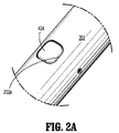
ここで図2〜図3を参照すると、細長道具200は、外側本体またはシェル202を備え、この外側本体またはシェルは、ファスナーを発射するためのファスナー発射機構の構成要素、およびアンビル304とファスナーカートリッジ302とを近接させるための近接機構の構成要素を収容する。外側本体202は、近位または後端202a、および遠位または前端202bを規定する。細長道具200は、アンビル保持具またはトロカール204をさらに備え、このアンビル保持具またはトロカールは、外側本体202に、そしてファスナーカートリッジ302に対して、解放可能に設置される。図2において、ファスナーカートリッジ302は、細長道具200の外側本体202から(図示の目的で)取り外されて示されている。アンビル保持具204(その一部分のみが図2に示されている)は、アンビル304をファスナーカートリッジ302に対して固定および/または設置し、そしてトロカールとして機能して、アンビル304が設置されない状態で、細長道具200を組織に通して前進させることを補助し得る。
Referring now to FIGS. 2-3, the
図3に最もよく図示されるように、アンビル保持具204は、保持具スリーブ206、およびスリーブ206に解放可能に設置されたアンビル保持具シャフト208を備える。スリーブ206は、スリーブ206の壁を少なくとも部分的にかまたは完全に通って延びる、少なくとも1個の設置穴210を備える。1つの実施形態において、スリーブ206は、同じ軸方向位置に配置された、直径方向に対向する1対の設置穴210(図3には1個のみの設置穴210が示される)を備える。設置穴210は、寸法が円形であってもよいが、他の構成も同様に想定される。スリーブ206は、1個またはより多くの助穴212を備えてもよく、または必要に応じて、助穴212を有さなくてもよい。助穴212は、外側スリーブ206のある程度の拡張を可能にして、保持具シャフト208のスリーブ206内での挿入および/または保持を容易にし得るか、あるいは保持具シャフト208の協働する構造体を係合して、保持具シャフト208をスリーブ206内で固定することを補助し得る。
As best illustrated in FIG. 3, the
保持具シャフト208は、従来の配置(例えば、摩擦ばめ、差し込みカップリング、または移動止め機構など)によって、スリーブ206内に解放可能に固定され得る。保持具シャフト208は、遠位トロカール先端214を備え得、この遠位トロカール先端は、テーパ状の構成を有して、組織の通過を容易にし、アンビル保持具204がトロカールのように機能することを補助する。保持具シャフト208は、アンビル304の対応する構造体と連結して、アンビル304をアンビル保持具204に解放可能に連結するような寸法にされる。代替例において、スリーブ206と保持具シャフト208とは、互いに固定された関係で固定され得る。
The
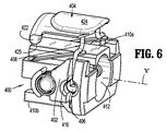
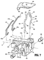
ここで図4〜図7を参照して、アンビル保持具204を細長道具200の外側本体202に対して解放可能に設置するための、アンビル保持具解放機構400が議論される。解放機構400は、細長道具200の外側本体202に、エンドエフェクタ300の近位で設置される。図4において、エンドエフェクタ300は図示されていない。解放機構400を外側本体202またはその内部に固定するための任意の従来の手段が想定され、これらの手段としては、機械的配置、または接着剤などが挙げられる。図6〜図7に最もよく図示されるように、解放機構400は、ハウジング軸「k」を規定する解放ハウジング402、手動で作動可能な解放具404、1対のロック406およびロックドライブ408を備える。手動で作動可能な解放具404、ロック406およびロックドライブ408はそれぞれ、解放ハウジング402に対してその内部での移動のために設置される。1つの実施形態において、解放ハウジング402は、上表面410aおよび下表面410b、アンビル保持具204の受容のための中心軸方向ボア412、それぞれのロック406を受容するための、ハウジング軸「k」に直交する第一および第二のロック受容ボア414、ならびにロックドライブ408を少なくとも部分的に受容するための第一および第二のチャネル416を備える。解放機構400は、1対のばね418(例えば、板ばね)をさらに備え得、これらのばねは、一端418aが解放ハウジング402の開口部420内に固定され、そして他方の自由端418bは、本明細書中以下で議論されるように、ロックドライブ408と係合している。
4-7, an anvil
図4〜図7の参照を続けると、手動で作動可能な解放具404は、少なくとも1個の円柱形ヒンジまたはピボット422(例えば、間隔を空けた2個のヒンジ422)、およびピボットヒンジ422から延びる手動係合セグメント424を備える。ヒンジ422は、手動で作動可能な解放具404がその第一の位置と第二の位置との間で動く間に、解放ハウジング402の上表面410aの凹部(単数または複数)425(図5)の内部で回転する。あるいは、ヒンジ422に適応する凹部は、外側本体202に関連してもよい。図4〜図6において、手動で作動可能な解放具404は第一の位置にあり、この第一の位置は、アンビル保持具204の、細長道具200および/またはファスナーカートリッジ302に対する固定された状態に対応し得る。手動で作動可能な解放具404の手動係合セグメント424は、図2Aに図示されるような、細長道具200の外側本体202の窓202aを通して、医師によるアクセスのために、アクセス可能である。
Continuing with reference to FIGS. 4-7, the manually
図5〜図7を、図8の断面図と合わせて参照すると、ロックドライブ408は、ハウジング軸「k」に対して下向き、または半径方向内向きに、手動で作動可能な解放具404からぶら下がり、そして手動で作動可能な解放具404に固定されていても固定されていなくてもよい。図7〜図8に最もよく図示されるように、ロックドライブ408は、中心梁426、および中心梁426から延びる2本のレッグ428を備える。中心梁426は、手動で作動可能な解放具404の手動係合セグメント424を係合する。ロックドライブ408の2本のレッグ428は、対向するレッグセグメント430を備え、これらのレッグセグメントは、中心梁426から連続的に延び、中心梁426の半径方向外向きに配置された、1対の凹状または外向きのセグメント432まで続く。ロックドライブ408のレッグ428は、1対の内向きにテーパ状のセグメントまたはカムセグメント434をさらに規定し、これらのカムセグメントは、外側セグメント432から連続的にぶら下がり、そして下レッグセグメント436まで続く。
Referring to FIGS. 5-7 in conjunction with the cross-sectional view of FIG. 8, the
図7〜図8の参照を続けると、解放機構400のロック406の各々は、それぞれのロック406のおよそ中央セクションを通って延びる通路438を規定し、これらの通路はまた、通路438と連絡する上リリーフエリア440および下リリーフエリア442を規定する。通路438は、ロックドライブ408のレッグ428(例えば、少なくとも下レッグセグメント436)を少なくとも部分的に受容する。手動で作動可能な解放具404の第一の位置(アンビル保持具204に対するロック406のロックされた位置に対応する)において、下レッグセグメント436は、通路438内に配置されて、ロック406をアンビル保持具204のスリーブ206の設置穴210内に配置する(図8)。これは、アンビル204の、ファスナーカートリッジ302および/または細長道具200に対する固定された状態に対応する。手動で作動可能な解放具404は通常、自由端418bがロックドライブ408のシェルフ444に係合している1対のばね418によって、第一の状態に付勢されており、これによって、ロックドライブ408を上向き、すなわち起動されていない位置に駆動し、そして手動で作動可能な解放具404を、図8の第一の位置に駆動する。
With continued reference to FIGS. 7-8, each of the
図8はまた、1対のプッシャ446および1対の近接器シャフト448を図示する。これらのプッシャは、解放ハウジング402を通って延び(例えば、上表面410aおよび下表面410bに沿って載り得る)、そして細長道具200を通って延びるファスナー発射機構、およびファスナーカートリッジ302と連結する。これらの近接器シャフトは、アンビル保持具204および/またはアンビル304のいずれかと連結して、アンビル304を、ファスナーカートリッジ302に対して開状態と近接状態との間で移動させる。近接器シャフト448は、手動で作動可能な解放具404の、間隔を空けたヒンジ422間に延び得る。
FIG. 8 also illustrates a pair of
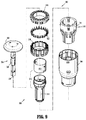
ここで図9を参照すると、細長道具200と一緒に使用するための1つの例示的なエンドエフェクタ300が図示されている。エンドエフェクタ300の特徴は、同一人に譲渡された、Millimanに対する米国特許出願公開第2015/0014393号に開示されており、その全内容は、本明細書中に参考として援用される。エンドエフェクタ300のファスナーカートリッジ302は、ハウジング306、プッシャアセンブリ308、ファスナーカートリッジ310、およびナイフアセンブリ312を備える。プッシャアセンブリ308は、プッシャアダプタ314およびプッシャ部材316を備え、このプッシャ部材は、細長道具200の外側本体202内に延びる1対のプッシャ446(図8)と連結する。ナイフアセンブリ312は、ナイフキャリア318および円形ナイフ320を備え、これらは、プッシャ446に作動可能に連結され得る。ファスナーカートリッジ310は、ファスナーカートリッジ310の凹部324内に設置された、複数のファスナーまたはステープル322を備える。
Referring now to FIG. 9, one
図9を続けて参照すると、エンドエフェクタ300のアンビル304は、アンビルシャフト326を備え、このアンビルシャフトは、アンビル保持具204の保持具シャフト208の少なくとも部分的な受容のための、長手軸方向ボア328を規定する。長手軸方向ボア328内に配置されるとき、保持具シャフト208とアンビル304とは、互いに連結される。アンビル304は、ポケット(図示せず)を備える円形アンビルヘッド330を備え、これらのポケットは、ファスナーカートリッジ310によって排出されるファスナーまたはステープル322を受容してクリンプする。ある実施形態において、アンビル304とアンビル保持具204とは、1つの構成要素であり得る。従って、アンビル保持具204の設置および解放は、アンビル304の対応する設置および解放を引き起こす。
With continued reference to FIG. 9, the
1つの例示的な使用において、ファスナーカートリッジ310およびアンビル保持具204が設置された細長道具200は、管状身体器官のセクション内に前進させられる。示されるように、保持具シャフト208の遠位トロカール先端214は、この組織の器官を通る通過を容易にし得る。アンビル304は、ファスナーカートリッジ310と対向する関係で、管状身体器官の第二のセクションで前進または配置される。この管状身体器官の第一のセクションおよび第二のセクションの端部は、それぞれファスナーカートリッジ310およびアンビルヘッド330の周囲で固定される。アンビルシャフト326は、保持具シャフト208に設置され、そしてアンビル304とファスナーカートリッジ302とは、ハンドル枠102のアクチュエータのうちの1つの作動によって、近接させられる。プッシャアセンブリ308は、(例えば、ハンドル100の起動および解放ハウジング402内でのプッシャ446の移動により)前進させられて、プッシャ部材316およびナイフアセンブリ312の前進移動を引き起こし、ファスナーまたはステープル322をアンビルヘッド330に対するクリンプのために排出し、そして接続された器官内に位置するあらゆる組織を切り開く。
In one exemplary use,
ここで図10〜図11を参照して、解放機構400の使用が記載される。医師によって、アンビル保持具204(アンビル304が設置されているかまたは設置されていない)が細長道具200の外側本体202から解放されるべきであることが決定される場合、例えば、上記吻合手順の後に、手動で作動可能な解放具404の手動係合セグメント424は、軸「k」に対して内向きに、「m」の方向に押されて、この手動係合セグメントを、ピボットヒンジ422の周りで、ばね418の付勢に逆らって旋回させて、その第二の位置(アンビル204の、ファスナーカートリッジ302および/または細長道具200に対する解放状態に対応する)を取らせる。これにより、ロックドライブ408もまた、ばね418の付勢に逆らって「m」の方向に、例えばその起動された位置に移動する。ロックドライブ408の移動中に、レッグ428のカムセグメント434は、ロック406の通路438を横断し、そしてカムセグメント434の、上リリーフエリア440および下リリーフエリア442の内側表面440i、442i、ならびに/またはロック406の通路438の内側表面438iのうちの少なくとも1つとのカム作用に起因して、ロック406を半径方向外向きの方向(方向矢印「b」に対応する)に変位させる。ロック406の半径方向外向きへの移動の結果として、ロック406は、スリーブ206の設置穴210から変位し(ロック406のロック解除された位置に対応する)、これによって、図12に図示されるように、スリーブ206およびアンビル保持具204の全体(ならびにアンビル保持具204に設置されている場合には、アンビル304)を、細長道具200からの取り外しのために自由にする。従って、アンビル保持具204の取り外しは、手動で作動可能な解放具404の単なる押下によって、行われ得る。
The use of the
図13に図示されるように、手動で作動可能な解放具404の解放のときに、ロックドライブ408および手動で作動可能な解放具404は、ばね418の付勢と、ロックドライブ408のカムセグメント434(通路438によって規定される内部表面438i、440i、442i、およびロック406のリリーフエリア440、442のうちの少なくとも1つを係合し、これによって、ロック406をそのロックされた位置に配置する)との影響下で、それぞれの起動されていない位置および第一の位置に戻る。別のアンビル保持具204(新しいもの、または滅菌されて再使用されるもの)を装填するために、手動で作動可能な解放具404が押下されて、その第二の位置への移動、およびロック406の、そのロック解除された位置への半径方向外向きへの変位を引き起こし得る。アンビル保持具204は、解放ハウジング402の中心軸方向ボア412内に導入され、そして手動で作動可能な解放具404は解放されて、その第二の位置のロックを呈し、これによって、ロック406は、アンビル保持具204のスリーブ206の設置穴210に受容されたロックされた位置に戻って、アンビル保持具204またはトロカールを、細長道具200に対して固定する。アンビル304は、アンビル保持具204を解放ハウジング402に設置する前、設置中、または設置した後に、スリーブ206に導入され得る。
As shown in FIG. 13, upon release of the manually actuated
上記説明および図面は、本開示の実施形態を説明する目的で提供されるのであり、いかなる方法でも本開示の範囲を限定することは意図されない。例えば、モータ駆動式のハンドルが示されるが、本発明のロック装置は、手動で作動可能なハンドルを備えるデバイス、またはロボットシステムに提供され得る。種々の改変およびバリエーションが、本開示の趣旨および範囲から逸脱することなくなされ得ることが、当業者に明らかである。従って、本開示は、本開示の改変およびバリエーションが添付の特許請求の範囲およびその均等物の範囲内であることを条件として、これらの改変およびバリエーションを網羅することが意図される。 The above description and drawings are provided for the purpose of illustrating embodiments of the present disclosure and are not intended to limit the scope of the present disclosure in any way. For example, although a motor driven handle is shown, the locking device of the present invention may be provided in a device with a manually actuable handle or in a robotic system. It will be apparent to those skilled in the art that various modifications and variations can be made without departing from the spirit and scope of the disclosure. Accordingly, this disclosure is intended to cover these modifications and variations, provided that such modifications and variations are within the scope of the appended claims and their equivalents.
Claims (16)
該本体の該遠位端に隣接して配置されるファスナーカートリッジ;
該ファスナーカートリッジに対して解放可能に設置されるアンビル保持具;ならびに
該ファスナーカートリッジに対する該アンビル保持具の固定された状態に対応する第一の位置と、該ファスナーカートリッジに対する該アンビル保持具の解放状態に対応する第二の位置との間で移動するように構成されている、手動で作動可能な解放具
を備える、外科手術用円形ファスナー装置。 An elongate body defining a longitudinal axis and having a proximal end and a distal end;
A fastener cartridge disposed adjacent to the distal end of the body;
An anvil holder releasably installed with respect to the fastener cartridge; and a first position corresponding to a fixed state of the anvil holder with respect to the fastener cartridge; and a released state of the anvil holder with respect to the fastener cartridge. A surgical circular fastener device comprising a manually actuable release device configured to move between a second position corresponding to.
該細長本体の該遠位端に隣接して配置されるファスナーカートリッジ;
該ファスナーカートリッジに対して解放可能に設置されるアンビル保持具であって、少なくとも1つのロック凹部を規定する、アンビル保持具;ならびに
該アンビル保持具を該ファスナーカートリッジに対して選択的に固定および解放するためのアンビル保持具解放機構
を備え、該アンビル保持具解放機構は:
解放ハウジング;
該保持具ハウジングに設置され、第一の位置と第二の位置との間で移動するように構成されている、手動で作動可能な解放具;および
該手動で作動可能な解放具に作動可能に連結された少なくとも1つのロックであって、該少なくとも1つのロックは、該手動で作動可能な解放具の第一の位置と第二の位置との間での移動のときに、該保持具ハウジング内で、それぞれロックされた位置とロック解除された位置との間での移動のために設置されており、該少なくとも1つのロックは、該ロックされた位置にあるときに、該アンビル保持具の該少なくとも1つのロック凹部に受容されて、該アンビル保持具を該ファスナーカートリッジに対して固定するように構成されており、そして該ロック解除された位置にあるときに、該少なくとも1つのロック凹部から解放されて該アンビル保持具を解放し、該アンビル保持具の該ファスナーカートリッジに対する設置または解放を可能にするように構成されている、少なくとも1つのロック
を備える、外科手術用円形ファスナー装置。 An elongate body defining a longitudinal axis and having a front end and a rear end;
A fastener cartridge disposed adjacent to the distal end of the elongate body;
An anvil retainer releasably installed relative to the fastener cartridge, the anvil retainer defining at least one locking recess; and selectively securing and releasing the anvil retainer relative to the fastener cartridge An anvil retainer release mechanism for performing an anvil retainer release mechanism comprising:
Release housing;
A manually actuable release device installed in the retainer housing and configured to move between a first position and a second position; and actuable on the manually actuated release device At least one lock coupled to the retainer when the manually actuated release device is moved between a first position and a second position. Installed within the housing for movement between a locked position and an unlocked position, said at least one lock being in said locked position when said anvil retainer is in said locked position Is received in the at least one locking recess and is configured to secure the anvil retainer relative to the fastener cartridge and when in the unlocked position, the at least one Surgical circular fastener device comprising at least one lock configured to be released from a lock recess to release the anvil retainer and allow the anvil retainer to be installed or released from the fastener cartridge. .
Applications Claiming Priority (2)
| Application Number | Priority Date | Filing Date | Title |
|---|---|---|---|
| US14/737,552 | 2015-06-12 | ||
| US14/737,552 US9987001B2 (en) | 2015-06-12 | 2015-06-12 | Surgical anastomosis apparatus |
Publications (2)
| Publication Number | Publication Date |
|---|---|
| JP2017000751A true JP2017000751A (en) | 2017-01-05 |
| JP6765861B2 JP6765861B2 (en) | 2020-10-07 |
Family
ID=56119383
Family Applications (1)
| Application Number | Title | Priority Date | Filing Date |
|---|---|---|---|
| JP2016111811A Active JP6765861B2 (en) | 2015-06-12 | 2016-06-03 | Surgical anastomosis device |
Country Status (6)
| Country | Link |
|---|---|
| US (2) | US9987001B2 (en) |
| EP (1) | EP3103402B1 (en) |
| JP (1) | JP6765861B2 (en) |
| AU (1) | AU2016203545B2 (en) |
| CA (1) | CA2931516A1 (en) |
| ES (1) | ES2894294T3 (en) |
Families Citing this family (37)
| Publication number | Priority date | Publication date | Assignee | Title |
|---|---|---|---|---|
| US8360296B2 (en) | 2010-09-09 | 2013-01-29 | Ethicon Endo-Surgery, Inc. | Surgical stapling head assembly with firing lockout for a surgical stapler |
| US8632462B2 (en) | 2011-03-14 | 2014-01-21 | Ethicon Endo-Surgery, Inc. | Trans-rectum universal ports |
| US9730694B2 (en) * | 2014-07-01 | 2017-08-15 | Covidien Lp | Loading unit including shipping assembly |
| US10226254B2 (en) * | 2014-10-21 | 2019-03-12 | Covidien Lp | Adapter, extension, and connector assemblies for surgical devices |
| US9987001B2 (en) | 2015-06-12 | 2018-06-05 | Covidien Lp | Surgical anastomosis apparatus |
| US10111684B2 (en) | 2015-09-25 | 2018-10-30 | Covidien Lp | Adapter assembly including a removable trocar assembly |
| US10456140B2 (en) | 2016-04-01 | 2019-10-29 | Ethicon Llc | Surgical stapling system comprising an unclamping lockout |
| US11284890B2 (en) | 2016-04-01 | 2022-03-29 | Cilag Gmbh International | Circular stapling system comprising an incisable tissue support |
| US10413293B2 (en) | 2016-04-01 | 2019-09-17 | Ethicon Llc | Interchangeable surgical tool assembly with a surgical end effector that is selectively rotatable about a shaft axis |
| US10485542B2 (en) | 2016-04-01 | 2019-11-26 | Ethicon Llc | Surgical stapling instrument comprising multiple lockouts |
| US10426470B2 (en) * | 2016-11-04 | 2019-10-01 | Covidien Lp | Stapling device with releasable knife carrier |
| US10603041B2 (en) * | 2016-11-14 | 2020-03-31 | Ethicon Llc | Circular surgical stapler with angularly asymmetric deck features |
| US10420551B2 (en) | 2017-05-30 | 2019-09-24 | Covidien Lp | Authentication and information system for reusable surgical instruments |
| US11045199B2 (en) | 2017-06-09 | 2021-06-29 | Covidien Lp | Handheld electromechanical surgical system |
| US10932784B2 (en) * | 2017-06-09 | 2021-03-02 | Covidien Lp | Handheld electromechanical surgical system |
| US11896230B2 (en) * | 2018-05-07 | 2024-02-13 | Covidien Lp | Handheld electromechanical surgical device including load sensor having spherical ball pivots |
| US11534172B2 (en) * | 2018-05-07 | 2022-12-27 | Covidien Lp | Electromechanical surgical stapler including trocar assembly release mechanism |
| US11399839B2 (en) * | 2018-05-07 | 2022-08-02 | Covidien Lp | Surgical devices including trocar lock and trocar connection indicator |
| US11389263B2 (en) * | 2018-12-13 | 2022-07-19 | Covidien Lp | Lockout mechanisms for surgical instruments |
| US11337701B2 (en) * | 2019-03-01 | 2022-05-24 | Covidien Lp | Devices and methods for assembling adapter assemblies |
| CN111820981A (en) * | 2019-04-22 | 2020-10-27 | 柯惠Lp公司 | Surgical device including trocar lock and trocar connection indicator |
| CN111820982A (en) * | 2019-04-22 | 2020-10-27 | 柯惠Lp公司 | Electromechanical surgical stapler including trocar assembly release mechanism |
| AU2019448247A1 (en) * | 2019-05-31 | 2021-12-16 | Covidien Lp | Circular stapling device |
| US11464541B2 (en) * | 2019-06-24 | 2022-10-11 | Covidien Lp | Retaining mechanisms for trocar assembly |
| US11123101B2 (en) * | 2019-07-05 | 2021-09-21 | Covidien Lp | Retaining mechanisms for trocar assemblies |
| US11446035B2 (en) * | 2019-06-24 | 2022-09-20 | Covidien Lp | Retaining mechanisms for trocar assemblies |
| US11426168B2 (en) * | 2019-07-05 | 2022-08-30 | Covidien Lp | Trocar coupling assemblies for a surgical stapler |
| US11344309B2 (en) * | 2019-07-05 | 2022-05-31 | Covidien Lp | Circular stapling instruments |
| US11517317B2 (en) * | 2020-01-06 | 2022-12-06 | Covidien Lp | Trocar release assemblies for a surgical stapler |
| US11730481B2 (en) * | 2020-01-06 | 2023-08-22 | Covidien Lp | Assemblies for retaining a trocar assembly |
| US11534173B2 (en) * | 2020-03-06 | 2022-12-27 | Covidien Lp | Surgical stapling instrument with telescopic trocar assembly |
| US11426169B2 (en) | 2020-03-24 | 2022-08-30 | Covidien Lp | Retaining mechanisms for trocar assemblies |
| US11350939B2 (en) * | 2020-03-24 | 2022-06-07 | Covidien Lp | Retaining mechanisms for trocar assemblies |
| US11426170B2 (en) | 2020-03-24 | 2022-08-30 | Covidien Lp | Retaining mechanisms for trocar assemblies |
| US11877744B2 (en) | 2020-08-14 | 2024-01-23 | Covidien Lp | Low-cost powered stapler with end stop selection |
| US11819208B2 (en) | 2021-08-05 | 2023-11-21 | Covidien Lp | Handheld electromechanical surgical device with strain gauge drift detection |
| US11744592B2 (en) | 2021-08-05 | 2023-09-05 | Covidien Lp | Handheld electromechanical stapler with tissue thickness detection |
Citations (4)
| Publication number | Priority date | Publication date | Assignee | Title |
|---|---|---|---|---|
| JP2007508869A (en) * | 2003-10-17 | 2007-04-12 | タイコ ヘルスケア グループ リミテッド パートナーシップ | Surgical stapling device |
| US20140305990A1 (en) * | 2013-04-16 | 2014-10-16 | Ethicon Endo-Surgery, Inc. | Drive system decoupling arrangement for a surgical instrument |
| JP2015506223A (en) * | 2012-01-05 | 2015-03-02 | エシコン・エンド−サージェリィ・インコーポレイテッドEthicon Endo−Surgery,Inc. | Tissue stapler anvil mechanism to prevent early jaw opening |
| US20150150574A1 (en) * | 2013-12-04 | 2015-06-04 | Covidien Lp | Adapter direct drive push button retention mechanism |
Family Cites Families (385)
| Publication number | Priority date | Publication date | Assignee | Title |
|---|---|---|---|---|
| CA908529A (en) | 1972-08-29 | V. Astafiev Georgy | Surgical instrument for suturing hollow organs in infants | |
| DE1057729B (en) | 1954-03-29 | 1959-05-21 | Lameris Instr N V | Surgical device for connecting two parts of the intestine |
| GB787043A (en) | 1954-09-15 | 1957-11-27 | Sylvania Electric Prod | Method for production of silicon |
| CA736256A (en) | 1962-08-27 | 1966-06-14 | S. Kasoolin Viacheslav | Instrument for suturing esophagus to intestine or stomach |
| FR1461464A (en) | 1965-08-20 | 1966-02-25 | Niiex Khirurgicheskoi Apparatu | Surgical device for suturing organs |
| CH470170A (en) | 1968-02-02 | 1969-03-31 | Vnii Khirurgicheskoi Apparatur | Device for applying round anastomoses |
| US3638652A (en) | 1970-06-01 | 1972-02-01 | James L Kelley | Surgical instrument for intraluminal anastomosis |
| US3771526A (en) | 1972-02-07 | 1973-11-13 | P Rudie | Anastomosis clamp |
| US4603693A (en) | 1977-05-26 | 1986-08-05 | United States Surgical Corporation | Instrument for circular surgical stapling of hollow body organs and disposable cartridge therefor |
| US4573468A (en) | 1977-05-26 | 1986-03-04 | United States Surgical Corporation | Hollow body organ stapling instrument and disposable cartridge employing relief vents |
| US4304236A (en) | 1977-05-26 | 1981-12-08 | United States Surgical Corporation | Stapling instrument having an anvil-carrying part of particular geometric shape |
| NL7711347A (en) | 1977-10-17 | 1979-04-19 | Carl Robert Erik Daantje | Stapling instrument for joining intestine ends - has head coupling rod in two parts screwing together with hand grip |
| US4207898A (en) | 1978-03-27 | 1980-06-17 | Senco Products, Inc. | Intralumenal anastomosis surgical stapling instrument |
| US4198982A (en) | 1978-03-31 | 1980-04-22 | Memorial Hospital For Cancer And Allied Diseases | Surgical stapling instrument and method |
| DE2947107A1 (en) | 1978-12-07 | 1980-06-26 | United States Surgical Corp | ACCURATELY ALIGNED CARTRIDGE AND INSTRUMENT FOR CLAMPING ANASTOMOSES |
| SU1088712A1 (en) | 1979-11-14 | 1984-04-30 | Всесоюзный научно-исследовательский и испытательный институт медицинской техники | Apparatus for circular suture of blood vessels |
| AU534210B2 (en) | 1980-02-05 | 1984-01-12 | United States Surgical Corporation | Surgical staples |
| US4319576A (en) | 1980-02-26 | 1982-03-16 | Senco Products, Inc. | Intralumenal anastomosis surgical stapling instrument |
| US4289133A (en) | 1980-02-28 | 1981-09-15 | Senco Products, Inc. | Cut-through backup washer for the scalpel of an intraluminal surgical stapling instrument |
| US4606343A (en) | 1980-08-18 | 1986-08-19 | United States Surgical Corporation | Self-powered surgical fastening instrument |
| US4351466A (en) | 1980-10-16 | 1982-09-28 | United States Surgical Corporation | Disposable instrument for surgical fastening |
| US4379457A (en) | 1981-02-17 | 1983-04-12 | United States Surgical Corporation | Indicator for surgical stapler |
| US4476863A (en) | 1981-03-09 | 1984-10-16 | Kanshin Nikolai N | Surgical instrument for establishing circular coloanastomoses |
| US4632290A (en) | 1981-08-17 | 1986-12-30 | United States Surgical Corporation | Surgical stapler apparatus |
| US4576167A (en) | 1981-09-03 | 1986-03-18 | United States Surgical Corporation | Surgical stapler apparatus with curved shaft |
| SU1114405A1 (en) | 1982-02-23 | 1984-09-23 | Всесоюзный научно-исследовательский и испытательный институт медицинской техники | Surgical suturing apparatus for placing compression anastomoses on the organs of digestive tract |
| US4473077A (en) | 1982-05-28 | 1984-09-25 | United States Surgical Corporation | Surgical stapler apparatus with flexible shaft |
| US4485817A (en) | 1982-05-28 | 1984-12-04 | United States Surgical Corporation | Surgical stapler apparatus with flexible shaft |
| US4488523A (en) | 1982-09-24 | 1984-12-18 | United States Surgical Corporation | Flexible, hydraulically actuated device for applying surgical fasteners |
| US4505058A (en) * | 1983-01-06 | 1985-03-19 | Peterson Gerald A | Excavating tooth, holder and retainer |
| DE3301713A1 (en) | 1983-01-20 | 1984-07-26 | Horst Dr. 3004 Isernhagen Ziegler | Surgical clip suture apparatus for producing circular joins |
| US4592354A (en) | 1983-10-11 | 1986-06-03 | Senmed, Inc. | Tissue retention spool for intraluminal anastomotic surgical stapling instrument and methods |
| US4505414A (en) | 1983-10-12 | 1985-03-19 | Filipi Charles J | Expandable anvil surgical stapler |
| US4550870A (en) | 1983-10-13 | 1985-11-05 | Alchemia Ltd. Partnership | Stapling device |
| IT1173284B (en) | 1984-02-16 | 1987-06-18 | Riccardo Rosati | CIRCULAR MECHANICAL STAPLING MACHINE |
| US4667673A (en) | 1984-03-12 | 1987-05-26 | American Cyanamid Company | Anastomotic device applicator and method |
| US4671445A (en) | 1984-08-09 | 1987-06-09 | Baxter Travenol Laboratories, Inc. | Flexible surgical stapler assembly |
| US4754909A (en) | 1984-08-09 | 1988-07-05 | Barker John M | Flexible stapler |
| US4665917A (en) | 1985-01-28 | 1987-05-19 | Ethicon, Inc. | Tissue gripper for use with intraluminal stapling device |
| US4703887A (en) | 1985-01-28 | 1987-11-03 | Ethicon, Inc. | Collapsible purse string aid for use with intraluminal stapling device |
| AU582625B2 (en) | 1985-01-28 | 1989-04-06 | Ethicon Inc. | Tissue gripper for use with intraluminal stapling device |
| JPS635697Y2 (en) | 1985-04-04 | 1988-02-17 | ||
| JPS62140776A (en) | 1985-12-16 | 1987-06-24 | 海老原 代師行 | Stapler |
| US4903697A (en) | 1986-03-27 | 1990-02-27 | Semion Resnick | Cartridge assembly for a surgical stapling instrument |
| US4700703A (en) | 1986-03-27 | 1987-10-20 | Semion Resnick | Cartridge assembly for a surgical stapling instrument |
| ATE96633T1 (en) | 1986-04-21 | 1993-11-15 | Globe Control Finanz Aktienges | DEVICE FOR MAKING AN ANASTOMOSE. |
| US4752024A (en) | 1986-10-17 | 1988-06-21 | Green David T | Surgical fastener and surgical stapling apparatus |
| US4917114A (en) | 1986-10-17 | 1990-04-17 | United States Surgical Corporation | Surgical fastener and surgical stapling apparatus |
| US4776506A (en) | 1986-11-13 | 1988-10-11 | United States Surgical Corporation | Surgical stapler apparatus |
| US4873977A (en) | 1987-02-11 | 1989-10-17 | Odis L. Avant | Stapling method and apparatus for vesicle-urethral re-anastomosis following retropubic prostatectomy and other tubular anastomosis |
| US5119983A (en) | 1987-05-26 | 1992-06-09 | United States Surgical Corporation | Surgical stapler apparatus |
| US5158222A (en) | 1987-05-26 | 1992-10-27 | United States Surgical Corp. | Surgical stapler apparatus |
| US5285944A (en) | 1987-05-26 | 1994-02-15 | United States Surgical Corporation | Surgical stapler apparatus |
| SU1616624A1 (en) | 1987-07-14 | 1990-12-30 | Предприятие П/Я А-3697 | Surgical suturing apparatus |
| SU1509052A1 (en) | 1988-01-18 | 1989-09-23 | С. А. Попов | Surgical suturing apparatus |
| US4907591A (en) | 1988-03-29 | 1990-03-13 | Pfizer Hospital Products Group, Inc. | Surgical instrument for establishing compression anastomosis |
| US5193731A (en) | 1988-07-01 | 1993-03-16 | United States Surgical Corporation | Anastomosis surgical stapling instrument |
| US5005749A (en) | 1988-07-01 | 1991-04-09 | United States Surgical Corp. | Anastomosis surgical stapling instrument |
| ES2011110A6 (en) | 1988-09-02 | 1989-12-16 | Lopez Hervas Pedro | Hydraulic device with flexible body for surgical anastomosts |
| WO1990006085A1 (en) | 1988-11-29 | 1990-06-14 | Gingold Bruce S | Surgical stapling apparatus |
| US5197648A (en) | 1988-11-29 | 1993-03-30 | Gingold Bruce S | Surgical stapling apparatus |
| US4893662A (en) | 1988-12-06 | 1990-01-16 | Vito Gervasi | Cutting tool |
| CH677728A5 (en) | 1989-10-17 | 1991-06-28 | Bieffe Medital Sa | |
| US5366462A (en) | 1990-08-28 | 1994-11-22 | Robert L. Kaster | Method of side-to-end vascular anastomotic stapling |
| US5047039A (en) | 1990-09-14 | 1991-09-10 | Odis Lynn Avant | Method and apparatus for effecting dorsal vein ligation and tubular anastomosis and laparoscopic prostatectomy |
| US5253793A (en) | 1990-09-17 | 1993-10-19 | United States Surgical Corporation | Apparatus for applying two-part surgical fasteners |
| US5104025A (en) | 1990-09-28 | 1992-04-14 | Ethicon, Inc. | Intraluminal anastomotic surgical stapler with detached anvil |
| US5042707A (en) | 1990-10-16 | 1991-08-27 | Taheri Syde A | Intravascular stapler, and method of operating same |
| CA2055943C (en) | 1990-12-06 | 2003-09-23 | Daniel P. Rodak | Surgical fastening apparatus with locking mechanism |
| US5122156A (en) | 1990-12-14 | 1992-06-16 | United States Surgical Corporation | Apparatus for securement and attachment of body organs |
| US5222963A (en) | 1991-01-17 | 1993-06-29 | Ethicon, Inc. | Pull-through circular anastomosic intraluminal stapler with absorbable fastener means |
| CA2083965A1 (en) | 1991-03-29 | 1992-09-30 | Eric Perouse | Surgical stapler |
| US5221036A (en) | 1991-06-11 | 1993-06-22 | Haruo Takase | Surgical stapler |
| US5333773A (en) | 1991-08-23 | 1994-08-02 | Ethicon, Inc. | Sealing means for endoscopic surgical anastomosis stapling instrument |
| GR920100358A (en) | 1991-08-23 | 1993-06-07 | Ethicon Inc | Surgical anastomosis stapling instrument. |
| US5350104A (en) | 1991-08-23 | 1994-09-27 | Ethicon, Inc. | Sealing means for endoscopic surgical anastomosis stapling instrument |
| US5474223A (en) | 1991-10-18 | 1995-12-12 | United States Surgical Corporation | Surgical fastener applying apparatus |
| US5443198A (en) | 1991-10-18 | 1995-08-22 | United States Surgical Corporation | Surgical fastener applying apparatus |
| US5197649A (en) | 1991-10-29 | 1993-03-30 | The Trustees Of Columbia University In The City Of New York | Gastrointestinal endoscoptic stapler |
| US5433721A (en) | 1992-01-17 | 1995-07-18 | Ethicon, Inc. | Endoscopic instrument having a torsionally stiff drive shaft for applying fasteners to tissue |
| US5188638A (en) | 1992-02-06 | 1993-02-23 | Tzakis Andreas G | Apparatus and method for preforming anastomosis fastener securement of hollow organs |
| US5271543A (en) | 1992-02-07 | 1993-12-21 | Ethicon, Inc. | Surgical anastomosis stapling instrument with flexible support shaft and anvil adjusting mechanism |
| US5348259A (en) | 1992-02-10 | 1994-09-20 | Massachusetts Institute Of Technology | Flexible, articulable column |
| US5282810A (en) | 1992-04-08 | 1994-02-01 | American Cyanamid Company | Surgical anastomosis device |
| US5425738A (en) | 1992-04-08 | 1995-06-20 | American Cyanamid Company | Endoscopic anastomosis ring insertion device and method of use thereof |
| US5355897A (en) | 1992-04-16 | 1994-10-18 | Ethicon, Inc. | Method of performing a pyloroplasty/pylorectomy using a stapler having a shield |
| US5314435A (en) | 1992-05-19 | 1994-05-24 | United States Surgical Corporation | Anvil delivery system |
| US5344059A (en) | 1992-05-19 | 1994-09-06 | United States Surgical Corporation | Surgical apparatus and anvil delivery system therefor |
| JPH0647050A (en) | 1992-06-04 | 1994-02-22 | Olympus Optical Co Ltd | Tissue suture and ligature device |
| US5658300A (en) | 1992-06-04 | 1997-08-19 | Olympus Optical Co., Ltd. | Tissue fixing surgical instrument, tissue-fixing device, and method of fixing tissues |
| US5360154A (en) | 1992-07-17 | 1994-11-01 | United States Surgical Corporation | Apparatus for creating partial anastomoses |
| US5330486A (en) | 1992-07-29 | 1994-07-19 | Wilk Peter J | Laparoscopic or endoscopic anastomosis technique and associated instruments |
| US5261920A (en) | 1992-08-21 | 1993-11-16 | Ethicon, Inc. | Anvil bushing for circular stapler |
| US5368215A (en) | 1992-09-08 | 1994-11-29 | United States Surgical Corporation | Surgical apparatus and detachable anvil rod therefor |
| US5309927A (en) | 1992-10-22 | 1994-05-10 | Ethicon, Inc. | Circular stapler tissue retention spring method |
| US5314436A (en) | 1992-10-30 | 1994-05-24 | Wilk Peter J | Method and apparatus for performing end-to-end anastomoses |
| US5404870A (en) | 1993-05-28 | 1995-04-11 | Ethicon, Inc. | Method of using a transanal inserter |
| US5503320A (en) | 1993-08-19 | 1996-04-02 | United States Surgical Corporation | Surgical apparatus with indicator |
| US5454825A (en) | 1993-10-01 | 1995-10-03 | United States Surgical Corporation | Circular anastomosis device with seal |
| US5437684A (en) | 1993-10-01 | 1995-08-01 | United States Surgical Corporation | Circular anastomosis device |
| US5447514A (en) | 1993-10-01 | 1995-09-05 | United States Surgical Corporation | Circular anastomosis device |
| US5522534A (en) | 1993-10-01 | 1996-06-04 | United States Surgical Corporation | Anvil for surgical stapler |
| CA2132917C (en) | 1993-10-07 | 2004-12-14 | John Charles Robertson | Circular anastomosis device |
| US5503635A (en) | 1993-11-12 | 1996-04-02 | United States Surgical Corporation | Apparatus and method for performing compressional anastomoses |
| DE4407668A1 (en) | 1994-03-09 | 1995-09-14 | Ferdinand Dr Koeckerling | Surgical anastomotic ring setting device |
| US5464415A (en) | 1994-03-15 | 1995-11-07 | Chen; Te-Chuan | Sutureless intestinal anastomosis gun |
| US5860581A (en) | 1994-03-24 | 1999-01-19 | United States Surgical Corporation | Anvil for circular stapler |
| US5715987A (en) | 1994-04-05 | 1998-02-10 | Tracor Incorporated | Constant width, adjustable grip, staple apparatus and method |
| CA2147800C (en) | 1994-05-26 | 2006-07-11 | John Charles Robertson | Circular anastomosis device |
| AU696332B2 (en) | 1994-06-17 | 1998-09-10 | Heartport, Inc. | Surgical stapling instrument and method thereof |
| US5881943A (en) | 1994-06-17 | 1999-03-16 | Heartport, Inc. | Surgical anastomosis apparatus and method thereof |
| US5732872A (en) | 1994-06-17 | 1998-03-31 | Heartport, Inc. | Surgical stapling instrument |
| CA2146508C (en) | 1994-08-25 | 2006-11-14 | Robert H. Schnut | Anvil for circular stapler |
| US5685474A (en) | 1994-10-04 | 1997-11-11 | United States Surgical Corporation | Tactile indicator for surgical instrument |
| US7235089B1 (en) | 1994-12-07 | 2007-06-26 | Boston Scientific Corporation | Surgical apparatus and method |
| US5868760A (en) | 1994-12-07 | 1999-02-09 | Mcguckin, Jr.; James F. | Method and apparatus for endolumenally resectioning tissue |
| US5720755A (en) | 1995-01-18 | 1998-02-24 | Dakov; Pepi | Tubular suturing device and methods of use |
| US5904697A (en) | 1995-02-24 | 1999-05-18 | Heartport, Inc. | Devices and methods for performing a vascular anastomosis |
| DE19509115C2 (en) | 1995-03-16 | 1997-11-27 | Deutsche Forsch Luft Raumfahrt | Surgical device for preparing an anastomosis using minimally invasive surgical techniques |
| US5769841A (en) | 1995-06-13 | 1998-06-23 | Electroscope, Inc. | Electrosurgical apparatus for laparoscopic and like procedures |
| US5641111A (en) | 1995-06-28 | 1997-06-24 | Ethicon Endo-Surgery, Inc. | Surgical stapling instrument with anvil cutting guide |
| US5749896A (en) | 1995-07-18 | 1998-05-12 | Cook; Melvin S. | Staple overlap |
| US5839639A (en) | 1995-08-17 | 1998-11-24 | Lasersurge, Inc. | Collapsible anvil assembly and applicator instrument |
| US5814055A (en) | 1995-09-19 | 1998-09-29 | Ethicon Endo-Surgery, Inc. | Surgical clamping mechanism |
| JP3207436B2 (en) | 1995-10-31 | 2001-09-10 | オチコン アクツイエセルスカプ | Anastomotic device for use in performing an end-to-side anastomosis |
| US5836503A (en) | 1996-04-22 | 1998-11-17 | United States Surgical Corporation | Insertion device for surgical apparatus |
| US6050472A (en) | 1996-04-26 | 2000-04-18 | Olympus Optical Co., Ltd. | Surgical anastomosis stapler |
| US6119913A (en) | 1996-06-14 | 2000-09-19 | Boston Scientific Corporation | Endoscopic stapler |
| US20020019642A1 (en) | 1996-07-23 | 2002-02-14 | Keith Milliman | Anastomosis instrument and method for performing same |
| US5833698A (en) | 1996-07-23 | 1998-11-10 | United States Surgical Corporation | Anastomosis instrument and method |
| US6024748A (en) | 1996-07-23 | 2000-02-15 | United States Surgical Corporation | Singleshot anastomosis instrument with detachable loading unit and method |
| US6440146B2 (en) | 1996-07-23 | 2002-08-27 | United States Surgical Corporation | Anastomosis instrument and method |
| US5855312A (en) | 1996-07-25 | 1999-01-05 | Toledano; Haviv | Flexible annular stapler for closed surgery of hollow organs |
| US6338737B1 (en) | 1997-07-17 | 2002-01-15 | Haviv Toledano | Flexible annular stapler for closed surgery of hollow organs |
| US5865361A (en) | 1997-09-23 | 1999-02-02 | United States Surgical Corporation | Surgical stapling apparatus |
| US6117148A (en) | 1997-10-17 | 2000-09-12 | Ravo; Biagio | Intraluminal anastomotic device |
| US5951576A (en) | 1998-03-02 | 1999-09-14 | Wakabayashi; Akio | End-to-side vascular anastomosing stapling device |
| US6279809B1 (en) | 1998-03-10 | 2001-08-28 | Enrico Nicolo | Circular stapler for side to end, side to side and end to side anastomosis |
| KR20010052335A (en) | 1998-05-11 | 2001-06-25 | 클레어 티. 호브랜드 | Devices and methods for treating e.g. urinary stress incontinence |
| US6517566B1 (en) | 1998-05-11 | 2003-02-11 | Surgical Connections, Inc. | Devices and methods for treating e.g. urinary stress incontinence |
| US6478210B2 (en) | 2000-10-25 | 2002-11-12 | Scimed Life Systems, Inc. | Method and device for full thickness resectioning of an organ |
| US6629630B2 (en) | 1998-06-19 | 2003-10-07 | Scimed Life Systems, Inc. | Non-circular resection device and endoscope |
| US6601749B2 (en) | 1998-06-19 | 2003-08-05 | Scimed Life Systems, Inc. | Multi fire full thickness resectioning device |
| US6126058A (en) | 1998-06-19 | 2000-10-03 | Scimed Life Systems, Inc. | Method and device for full thickness resectioning of an organ |
| US6585144B2 (en) | 1998-06-19 | 2003-07-01 | Acimed Life Systems, Inc. | Integrated surgical staple retainer for a full thickness resectioning device |
| DE19837258A1 (en) | 1998-08-17 | 2000-03-02 | Deutsch Zentr Luft & Raumfahrt | Device for operating a surgical instrument for anastomosis of hollow organs |
| DE19836950B4 (en) | 1998-08-17 | 2004-09-02 | Deutsches Zentrum für Luft- und Raumfahrt e.V. | Surgical instrument in the form of a suturing device |
| US6203553B1 (en) | 1999-09-08 | 2001-03-20 | United States Surgical | Stapling apparatus and method for heart valve replacement |
| US6102271A (en) | 1998-11-23 | 2000-08-15 | Ethicon Endo-Surgery, Inc. | Circular stapler for hemorrhoidal surgery |
| US6142933A (en) | 1998-11-23 | 2000-11-07 | Ethicon Endo-Surgery, Inc. | Anoscope for hemorrhoidal surgery |
| US6083241A (en) | 1998-11-23 | 2000-07-04 | Ethicon Endo-Surgery, Inc. | Method of use of a circular stapler for hemorrhoidal procedure |
| US6626921B2 (en) | 1999-04-16 | 2003-09-30 | Integrated Vascular Interventional Technologies, L.C. | Externally positioned anvil apparatus for cutting anastomosis |
| US6652542B2 (en) | 1999-04-16 | 2003-11-25 | Integrated Vascular Interventional Technologies, L.C. (Ivit, Lc) | External anastomosis operators and related systems for anastomosis |
| US6551334B2 (en) | 1999-04-16 | 2003-04-22 | Integrated Vascular Interventional Technologies, Lc | Externally directed anastomosis systems and externally positioned anastomosis fenestra cutting apparatus |
| US6743244B2 (en) | 1999-04-16 | 2004-06-01 | Integrated Vascular Interventional Technologies, L.C. | Soft anvil apparatus for cutting anastomosis fenestra |
| US6402008B1 (en) | 1999-04-19 | 2002-06-11 | Deborah A. Lucas | Surgical stapler assembly with interchangeable heads |
| US6068636A (en) | 1999-04-23 | 2000-05-30 | Chen; Te-Chuan | Intra-intestinal bypass gun |
| US6716233B1 (en) | 1999-06-02 | 2004-04-06 | Power Medical Interventions, Inc. | Electromechanical driver and remote surgical instrument attachment having computer assisted control capabilities |
| US6315184B1 (en) | 1999-06-02 | 2001-11-13 | Powermed, Inc. | Stapling device for use with an electromechanical driver device for use with anastomosing, stapling, and resecting instruments |
| US7032798B2 (en) | 1999-06-02 | 2006-04-25 | Power Medical Interventions, Inc. | Electro-mechanical surgical device |
| US6443973B1 (en) | 1999-06-02 | 2002-09-03 | Power Medical Interventions, Inc. | Electromechanical driver device for use with anastomosing, stapling, and resecting instruments |
| US6981941B2 (en) | 1999-06-02 | 2006-01-03 | Power Medical Interventions | Electro-mechanical surgical device |
| US6793652B1 (en) | 1999-06-02 | 2004-09-21 | Power Medical Interventions, Inc. | Electro-mechanical surgical device |
| US6264087B1 (en) | 1999-07-12 | 2001-07-24 | Powermed, Inc. | Expanding parallel jaw device for use with an electromechanical driver device |
| US6491201B1 (en) | 2000-02-22 | 2002-12-10 | Power Medical Interventions, Inc. | Fluid delivery mechanism for use with anastomosing, stapling, and resecting instruments |
| US8025199B2 (en) | 2004-02-23 | 2011-09-27 | Tyco Healthcare Group Lp | Surgical cutting and stapling device |
| EP1251786B1 (en) | 2000-01-18 | 2007-03-14 | Tyco Healthcare Group Lp | Anastomosis instrument |
| HU225908B1 (en) | 2000-01-24 | 2007-12-28 | Ethicon Endo Surgery Europe | Surgical circular stapling head |
| US6193129B1 (en) | 2000-01-24 | 2001-02-27 | Ethicon Endo-Surgery, Inc. | Cutting blade for a surgical anastomosis stapling instrument |
| US6488197B1 (en) | 2000-02-22 | 2002-12-03 | Power Medical Interventions, Inc. | Fluid delivery device for use with anastomosing resecting and stapling instruments |
| US6533157B1 (en) | 2000-02-22 | 2003-03-18 | Power Medical Interventions, Inc. | Tissue stapling attachment for use with an electromechanical driver device |
| US6273897B1 (en) | 2000-02-29 | 2001-08-14 | Ethicon, Inc. | Surgical bettress and surgical stapling apparatus |
| WO2001066020A2 (en) | 2000-03-06 | 2001-09-13 | United States Surgical | Apparatus and method for performing a bypass procedure in a digestive system |
| IL139788A (en) | 2000-11-20 | 2006-10-05 | Minelu Zonnenschein | Stapler for endoscopes |
| US6592596B1 (en) | 2000-05-10 | 2003-07-15 | Scimed Life Systems, Inc. | Devices and related methods for securing a tissue fold |
| US20040267310A1 (en) | 2000-10-20 | 2004-12-30 | Racenet David C | Directionally biased staple and anvil assembly for forming the staple |
| US8286845B2 (en) | 2000-11-27 | 2012-10-16 | Boston Scientific Scimed, Inc. | Full thickness resection device control handle |
| US6821282B2 (en) | 2000-11-27 | 2004-11-23 | Scimed Life Systems, Inc. | Full thickness resection device control handle |
| US6398795B1 (en) | 2000-11-30 | 2002-06-04 | Scimed Life Systems, Inc. | Stapling and cutting in resectioning for full thickness resection devices |
| US6439446B1 (en) | 2000-12-01 | 2002-08-27 | Stephen J. Perry | Safety lockout for actuator shaft |
| US6503259B2 (en) | 2000-12-27 | 2003-01-07 | Ethicon, Inc. | Expandable anastomotic device |
| US6632237B2 (en) | 2001-01-11 | 2003-10-14 | Bio-Seal Tech, Inc. | Device and method for sealing a puncture in a blood vessel |
| CA2435209C (en) | 2001-01-24 | 2009-08-25 | Tyco Healthcare Group Lp | Anastomosis instrument and method for performing same |
| JP4202138B2 (en) | 2001-01-31 | 2008-12-24 | レックス メディカル インコーポレイテッド | Apparatus and method for stapling and ablating gastroesophageal tissue |
| US6769590B2 (en) | 2001-04-02 | 2004-08-03 | Susan E. Vresh | Luminal anastomotic device and method |
| AU2002257122B2 (en) | 2001-04-03 | 2006-09-14 | Covidien Lp | Surgical stapling device for performing circular anastomoses |
| US6632227B2 (en) | 2001-08-24 | 2003-10-14 | Scimed Life Systems, Inc. | Endoscopic resection devices |
| US20050107813A1 (en) | 2001-09-17 | 2005-05-19 | Vincente Gilete Garcia | Bone fixing device for cranial surgery |
| US6578751B2 (en) | 2001-09-26 | 2003-06-17 | Scimed Life Systems, Inc. | Method of sequentially firing staples using springs and a rotary or linear shutter |
| US20070060952A1 (en) | 2005-09-02 | 2007-03-15 | Roby Mark S | Surgical stapling device with coated knife blade |
| US6605098B2 (en) | 2001-09-28 | 2003-08-12 | Ethicon, Inc. | Surgical device for creating an anastomosis between first and second hollow organs |
| AU2002362751B2 (en) | 2001-10-05 | 2008-07-03 | Covidien Lp | Tilt top anvil for a surgical fastener device |
| US6605078B2 (en) | 2001-11-26 | 2003-08-12 | Scimed Life Systems, Inc. | Full thickness resection device |
| DE10158246C1 (en) | 2001-11-28 | 2003-08-21 | Ethicon Endo Surgery Europe | Surgical stapling instrument |
| US6981979B2 (en) | 2001-12-14 | 2006-01-03 | Enrico Nicolo | Surgical anastomotic devices |
| US20030111507A1 (en) | 2001-12-14 | 2003-06-19 | George Nunez | Balloon actuator for use in a resectioning device |
| US6905504B1 (en) | 2002-02-26 | 2005-06-14 | Cardica, Inc. | Tool for performing end-to-end anastomosis |
| US7128748B2 (en) | 2002-03-26 | 2006-10-31 | Synovis Life Technologies, Inc. | Circular stapler buttress combination |
| US7141055B2 (en) | 2002-04-24 | 2006-11-28 | Surgical Connections, Inc. | Resection and anastomosis devices and methods |
| WO2003090630A2 (en) | 2002-04-25 | 2003-11-06 | Tyco Healthcare Group, Lp | Surgical instruments including micro-electromechanical systems (mems) |
| US6685079B2 (en) | 2002-05-24 | 2004-02-03 | Scimed Life Systems, Inc. | Full thickness resectioning device |
| US6769594B2 (en) | 2002-05-31 | 2004-08-03 | Tyco Healthcare Group, Lp | End-to-end anastomosis instrument and method for performing same |
| US7195142B2 (en) | 2003-05-30 | 2007-03-27 | Tyco Healthcare Group Lp | End-to-end anastomosis instrument and method for performing same |
| ES2268384T3 (en) | 2002-06-17 | 2007-03-16 | Tyco Healthcare Group Lp | ANNULAR SUPPORT STRUCTURES. |
| IL150855A (en) | 2002-07-22 | 2007-06-03 | Leonid Monassevitch | Intratubular anastomosis apparatus |
| CA2754689C (en) | 2002-10-04 | 2014-12-16 | Tyco Healthcare Group Lp | Surgical stapling device |
| US7481347B2 (en) | 2002-10-04 | 2009-01-27 | Tyco Healthcare Group Lp | Pneumatic powered surgical stapling device |
| US7220237B2 (en) | 2002-10-23 | 2007-05-22 | Satiety, Inc. | Method and device for use in endoscopic organ procedures |
| AU2003297955A1 (en) | 2002-12-16 | 2004-07-22 | Edrich Vascular Devices, Inc. | Multiple stapling device for narrow blood vessels |
| AU2003303337B9 (en) | 2002-12-20 | 2008-11-20 | Covidien Lp | Vacuum assisted surgical stapler |
| US6852122B2 (en) | 2003-01-23 | 2005-02-08 | Cordis Corporation | Coated endovascular AAA device |
| KR100547166B1 (en) | 2003-04-11 | 2006-01-26 | 허윤석 | Improved circular stapler |
| CA2529446C (en) | 2003-06-20 | 2012-12-18 | Tyco Healthcare Group, Lp | Surgical stapling device |
| CA2531909C (en) | 2003-07-16 | 2011-02-15 | Tyco Healthcare Group Lp | Surgical stapling device with tissue tensioner |
| US7686201B2 (en) | 2003-09-01 | 2010-03-30 | Tyco Healthcare Group Lp | Circular stapler for hemorrhoid operations |
| US7547312B2 (en) | 2003-09-17 | 2009-06-16 | Gore Enterprise Holdings, Inc. | Circular stapler buttress |
| US7309341B2 (en) | 2003-09-30 | 2007-12-18 | Ethicon Endo-Surgery, Inc. | Single lumen anastomosis applier for self-deploying fastener |
| US7585306B2 (en) | 2003-12-24 | 2009-09-08 | Maquet Cardiovascular Llc | Anastomosis device, tools and methods of using |
| US8590764B2 (en) | 2003-12-24 | 2013-11-26 | Boston Scientific Scimed, Inc. | Circumferential full thickness resectioning device |
| CA2556422A1 (en) | 2004-02-17 | 2005-08-01 | Cook Biotech Incorporated | Medical devices and methods for applying bolster material |
| US6953138B1 (en) | 2004-02-18 | 2005-10-11 | Frank W. Dworak | Surgical stapler anvil with nested staple forming pockets |
| US7086267B2 (en) | 2004-02-18 | 2006-08-08 | Frank W. Dworak | Metal-forming die and method for manufacturing same |
| US7118528B1 (en) | 2004-03-16 | 2006-10-10 | Gregory Piskun | Hemorrhoids treatment method and associated instrument assembly including anoscope and cofunctioning tissue occlusion device |
| US8181840B2 (en) | 2004-03-19 | 2012-05-22 | Tyco Healthcare Group Lp | Tissue tensioner assembly and approximation mechanism for surgical stapling device |
| WO2005091986A2 (en) | 2004-03-19 | 2005-10-06 | Tyco Healthcare Group, Lp | Anvil assembly with improved cut ring |
| CA2566794A1 (en) | 2004-05-17 | 2005-12-08 | Datascope Investment Corp. | Surgical stapling system |
| JP4257270B2 (en) | 2004-07-14 | 2009-04-22 | オリンパス株式会社 | Biological tissue suturing method and biological tissue suturing device |
| US8317074B2 (en) | 2004-07-28 | 2012-11-27 | Ethicon Endo-Surgery, Inc. | Electroactive polymer-based articulation mechanism for circular stapler |
| US7182239B1 (en) | 2004-08-27 | 2007-02-27 | Myers Stephan R | Segmented introducer device for a circular surgical stapler |
| KR100646762B1 (en) | 2004-09-10 | 2006-11-23 | 인하대학교 산학협력단 | A staple for operation and a stapler for operation provided with the same |
| US8372094B2 (en) | 2004-10-15 | 2013-02-12 | Covidien Lp | Seal element for anastomosis |
| JP4801083B2 (en) | 2004-10-18 | 2011-10-26 | タイコ ヘルスケア グループ エルピー | Structure for applying a sprayable wound treatment material |
| WO2006044194A2 (en) | 2004-10-18 | 2006-04-27 | Tyco Healthcare Group, Lp | Compression anastomosis device and method |
| US7938307B2 (en) | 2004-10-18 | 2011-05-10 | Tyco Healthcare Group Lp | Support structures and methods of using the same |
| US7845536B2 (en) | 2004-10-18 | 2010-12-07 | Tyco Healthcare Group Lp | Annular adhesive structure |
| WO2006044494A2 (en) | 2004-10-18 | 2006-04-27 | Tyco Healthcare Group, Lp | Adhesive suture structure and methods of using the same |
| US7717313B2 (en) | 2004-10-18 | 2010-05-18 | Tyco Healthcare Group Lp | Surgical apparatus and structure for applying sprayable wound treatment material |
| ES2389208T3 (en) | 2004-10-18 | 2012-10-24 | Tyco Healthcare Group Lp | Annular adhesive structure |
| US7455682B2 (en) | 2004-10-18 | 2008-11-25 | Tyco Healthcare Group Lp | Structure containing wound treatment material |
| ITMI20042132A1 (en) | 2004-11-05 | 2005-02-05 | Ethicon Endo Surgery Inc | DEVICE AND METHOD FOR OBESITY THERAPY |
| US7207168B2 (en) | 2004-11-19 | 2007-04-24 | The Schnipke Family Limited Liability Company | Apparatus and method for inserting staple drivers in a cartridge |
| WO2006079260A1 (en) | 2005-01-26 | 2006-08-03 | Suzhou Touchstone International Medical Science Co., Ltd | A rotatable cutter head of a surgical stapler |
| US20060201989A1 (en) | 2005-03-11 | 2006-09-14 | Ojeda Herminio F | Surgical anvil and system for deploying the same |
| US9364229B2 (en) | 2005-03-15 | 2016-06-14 | Covidien Lp | Circular anastomosis structures |
| US7717312B2 (en) | 2005-06-03 | 2010-05-18 | Tyco Healthcare Group Lp | Surgical instruments employing sensors |
| US7959050B2 (en) | 2005-07-26 | 2011-06-14 | Ethicon Endo-Surgery, Inc | Electrically self-powered surgical instrument with manual release |
| US8627995B2 (en) | 2006-05-19 | 2014-01-14 | Ethicon Endo-Sugery, Inc. | Electrically self-powered surgical instrument with cryptographic identification of interchangeable part |
| US8573462B2 (en) | 2006-05-19 | 2013-11-05 | Ethicon Endo-Surgery, Inc. | Electrical surgical instrument with optimized power supply and drive |
| US9554803B2 (en) | 2005-07-26 | 2017-01-31 | Ethicon Endo-Surgery, Llc | Electrically self-powered surgical instrument with manual release |
| US20070029363A1 (en) | 2005-08-07 | 2007-02-08 | Sergey Popov | Surgical apparatus with remote drive |
| US8579178B2 (en) | 2005-08-15 | 2013-11-12 | Covidien Lp | Surgical stapling instruments including a cartridge having multiple staples sizes |
| US7398908B2 (en) | 2005-08-15 | 2008-07-15 | Tyco Healthcare Group Lp | Surgical stapling instruments including a cartridge having multiple staple sizes |
| US7407075B2 (en) | 2005-08-15 | 2008-08-05 | Tyco Healthcare Group Lp | Staple cartridge having multiple staple sizes for a surgical stapling instrument |
| US7401721B2 (en) | 2005-08-15 | 2008-07-22 | Tyco Healthcare Group Lp | Surgical stapling instruments including a cartridge having multiple staple sizes |
| US7771440B2 (en) | 2005-08-18 | 2010-08-10 | Ethicon Endo-Surgery, Inc. | Method and apparatus for endoscopically performing gastric reduction surgery in a single pass |
| US20070194079A1 (en) | 2005-08-31 | 2007-08-23 | Hueil Joseph C | Surgical stapling device with staple drivers of different height |
| CN2868208Y (en) | 2005-12-14 | 2007-02-14 | 苏州天臣国际医疗科技有限公司 | Tubular binding instrument having automatic safety unit |
| US7422138B2 (en) | 2006-02-01 | 2008-09-09 | Ethicon Endo-Surgery, Inc. | Elliptical intraluminal surgical stapler for anastomosis |
| US7793813B2 (en) | 2006-02-28 | 2010-09-14 | Tyco Healthcare Group Lp | Hub for positioning annular structure on a surgical device |
| US20100019016A1 (en) | 2006-03-23 | 2010-01-28 | Edoga John K | Vascular Anastomotic Staplers |
| EP1875870B1 (en) | 2006-07-07 | 2009-12-02 | Ethicon Endo-Surgery, Inc. | A surgical stapling instrument. |
| US7527185B2 (en) | 2006-07-12 | 2009-05-05 | Niti Surgical Solutions Ltd. | Compression anastomosis ring assembly and applicator for use therewith |
| US20080078802A1 (en) | 2006-09-29 | 2008-04-03 | Hess Christopher J | Surgical staples and stapling instruments |
| US7753246B2 (en) | 2007-01-31 | 2010-07-13 | Tyco Healthcare Group Lp | Surgical instrument with replaceable loading unit |
| US8272555B2 (en) | 2007-03-07 | 2012-09-25 | Tyco Healthcare Group Lp | Stapler for mucosectomy |
| US20090001121A1 (en) | 2007-03-15 | 2009-01-01 | Hess Christopher J | Surgical staple having an expandable portion |
| US7978403B2 (en) | 2007-05-10 | 2011-07-12 | Stc.Unm | Imaging interferometric microscopy |
| US8038045B2 (en) | 2007-05-25 | 2011-10-18 | Tyco Healthcare Group Lp | Staple buttress retention system |
| US7600663B2 (en) | 2007-07-05 | 2009-10-13 | Green David T | Apparatus for stapling and incising tissue |
| US7967181B2 (en) | 2007-08-29 | 2011-06-28 | Tyco Healthcare Group Lp | Rotary knife cutting systems |
| US20090082785A1 (en) | 2007-09-24 | 2009-03-26 | Milliman Keith L | Anvil Delivery Device Accessory |
| EP2200518B1 (en) | 2007-10-11 | 2012-04-25 | Karl-Wilhelm Ecker | Anastomotic tissue connection device |
| US8011554B2 (en) | 2008-01-09 | 2011-09-06 | Tyco Healthcare Group, Lp | Raised boss for staple guide |
| US8733611B2 (en) | 2008-03-12 | 2014-05-27 | Covidien Lp | Ratcheting mechanism for surgical stapling device |
| US8020741B2 (en) | 2008-03-18 | 2011-09-20 | Barosense, Inc. | Endoscopic stapling devices and methods |
| US8231041B2 (en) | 2008-04-14 | 2012-07-31 | Tyco Healthcare Group Lp | Variable compression surgical fastener cartridge |
| KR101565441B1 (en) | 2008-04-30 | 2015-11-03 | 각코우호우진 지치 이카다이가쿠 | Surgical system for natural orifice transluminal endoscopic surgery(notes) |
| US8011551B2 (en) | 2008-07-01 | 2011-09-06 | Tyco Healthcare Group Lp | Retraction mechanism with clutch-less drive for use with a surgical apparatus |
| US8678264B2 (en) | 2008-07-07 | 2014-03-25 | Covidien Lp | Surgical instrument with elongated channel |
| US8109426B2 (en) | 2008-08-12 | 2012-02-07 | Tyco Healthcare Group Lp | Surgical tilt anvil assembly |
| US8672931B2 (en) | 2008-08-18 | 2014-03-18 | 3JT Enterprises, LLC | Cryosurgical device with metered dose |
| US8113405B2 (en) | 2008-09-03 | 2012-02-14 | Tyco Healthcare Group, Lp | Surgical instrument with indicator |
| US20100051668A1 (en) | 2008-09-03 | 2010-03-04 | Milliman Keith L | Surgical instrument with indicator |
| US8181838B2 (en) | 2008-09-10 | 2012-05-22 | Tyco Healthcare Group Lp | Surgical stapling device |
| US7837080B2 (en) | 2008-09-18 | 2010-11-23 | Ethicon Endo-Surgery, Inc. | Surgical stapling instrument with device for indicating when the instrument has cut through tissue |
| US20100084453A1 (en) | 2008-10-03 | 2010-04-08 | Changzhou Waston Medical Appliance Co., Ltd | Circular stapler |
| US7918377B2 (en) | 2008-10-16 | 2011-04-05 | Ethicon Endo-Surgery, Inc. | Surgical stapling instrument with apparatus for providing anvil position feedback |
| US8231042B2 (en) | 2008-11-06 | 2012-07-31 | Tyco Healthcare Group Lp | Surgical stapler |
| US7886951B2 (en) | 2008-11-24 | 2011-02-15 | Tyco Healthcare Group Lp | Pouch used to deliver medication when ruptured |
| US8770460B2 (en) | 2008-12-23 | 2014-07-08 | George E. Belzer | Shield for surgical stapler and method of use |
| US8408441B2 (en) | 2009-01-06 | 2013-04-02 | Covidien Lp | Surgical stapler |
| US8066167B2 (en) | 2009-03-23 | 2011-11-29 | Ethicon Endo-Surgery, Inc. | Circular surgical stapling instrument with anvil locking system |
| US8418909B2 (en) | 2009-06-02 | 2013-04-16 | Covidien Lp | Surgical instrument and method for performing a resection |
| US8276802B2 (en) | 2009-07-11 | 2012-10-02 | Tyco Healthcare Group Lp | Surgical instrument with double cartridge and anvil assemblies |
| US8146790B2 (en) | 2009-07-11 | 2012-04-03 | Tyco Healthcare Group Lp | Surgical instrument with safety mechanism |
| US20110011916A1 (en) | 2009-07-16 | 2011-01-20 | New York University | Anastomosis device |
| US8328062B2 (en) | 2009-07-21 | 2012-12-11 | Covidien Lp | Surgical instrument with curvilinear tissue-contacting surfaces |
| US8267301B2 (en) | 2009-08-19 | 2012-09-18 | Tyco Healthcare Group Lp | Surgical stapler |
| HU229773B1 (en) | 2009-09-02 | 2014-06-30 | A tool for surgical intervention | |
| EP2494913B1 (en) | 2009-10-26 | 2018-12-12 | B. J. Zh. F. Panther Medical Equipment Co., Ltd. | Anorectal surgical instrument and anal dilator |
| US8322590B2 (en) | 2009-10-28 | 2012-12-04 | Covidien Lp | Surgical stapling instrument |
| US8413872B2 (en) | 2009-10-28 | 2013-04-09 | Covidien Lp | Surgical fastening apparatus |
| US8430292B2 (en) | 2009-10-28 | 2013-04-30 | Covidien Lp | Surgical fastening apparatus |
| US8899466B2 (en) | 2009-11-19 | 2014-12-02 | Ethicon Endo-Surgery, Inc. | Devices and methods for introducing a surgical circular stapling instrument into a patient |
| US8136712B2 (en) | 2009-12-10 | 2012-03-20 | Ethicon Endo-Surgery, Inc. | Surgical stapler with discrete staple height adjustment and tactile feedback |
| CN102188271B (en) | 2010-03-08 | 2012-10-10 | 北京中法派尔特医疗设备有限公司 | Nail pushing seat assembly capable of inclining laterally and resetting and anastomat adopting same |
| US8662370B2 (en) | 2010-04-08 | 2014-03-04 | Hidehisa Thomas Takei | Introducer system and assembly for surgical staplers |
| CA2743185A1 (en) | 2010-06-11 | 2011-12-11 | The Hospital For Sick Children | Device for performing end-to-end anastomosis |
| US8672207B2 (en) | 2010-07-30 | 2014-03-18 | Ethicon Endo-Surgery, Inc. | Transwall visualization arrangements and methods for surgical circular staplers |
| US8783543B2 (en) | 2010-07-30 | 2014-07-22 | Ethicon Endo-Surgery, Inc. | Tissue acquisition arrangements and methods for surgical stapling devices |
| US8360296B2 (en) | 2010-09-09 | 2013-01-29 | Ethicon Endo-Surgery, Inc. | Surgical stapling head assembly with firing lockout for a surgical stapler |
| US8998061B2 (en) | 2010-10-01 | 2015-04-07 | Covidien Lp | Surgical fastener applying apparatus |
| US20120145755A1 (en) | 2010-12-14 | 2012-06-14 | Pk Products, Llc | Tool securing device and methods related thereto |
| US8496157B2 (en) | 2011-02-18 | 2013-07-30 | Covidien Lp | Tilting anvil for annular surgical stapler |
| US8479968B2 (en) | 2011-03-10 | 2013-07-09 | Covidien Lp | Surgical instrument buttress attachment |
| US8632462B2 (en) | 2011-03-14 | 2014-01-21 | Ethicon Endo-Surgery, Inc. | Trans-rectum universal ports |
| JP5220153B2 (en) | 2011-03-29 | 2013-06-26 | 富士フイルム株式会社 | Tube anastomosis |
| US8789737B2 (en) | 2011-04-27 | 2014-07-29 | Covidien Lp | Circular stapler and staple line reinforcement material |
| US9649113B2 (en) | 2011-04-27 | 2017-05-16 | Covidien Lp | Device for monitoring physiological parameters in vivo |
| US8490850B2 (en) | 2011-04-29 | 2013-07-23 | Covidien Lp | Circular stapler with controlled tissue compression |
| US8733615B2 (en) | 2011-05-19 | 2014-05-27 | Ethicon Endo-Surgery, Inc. | Circular stapler with frictional reducing member |
| DE102011102686A1 (en) | 2011-05-20 | 2012-11-22 | Boris Vestweber | Anastomosis device and method for introducing an anastomosis device into a body lumen |
| HUE041474T2 (en) | 2011-08-24 | 2019-05-28 | Suzhou Touchstone Int Medical Science Co Ltd | Guiding device |
| US20130060258A1 (en) | 2011-08-26 | 2013-03-07 | Carman Giacomantonio | Endoluminal Surgical Instrument for Stapling, Cutting and Dividing |
| US8708212B2 (en) | 2011-10-18 | 2014-04-29 | Covidien Lp | Tilt top anvil with torsion spring |
| US9016547B2 (en) | 2011-10-26 | 2015-04-28 | Covidien Lp | EEA tilt top anvil with ratchet/locking mechanism |
| US9351731B2 (en) | 2011-12-14 | 2016-05-31 | Covidien Lp | Surgical stapling apparatus including releasable surgical buttress |
| US9010608B2 (en) | 2011-12-14 | 2015-04-21 | Covidien Lp | Releasable buttress retention on a surgical stapler |
| US9113885B2 (en) | 2011-12-14 | 2015-08-25 | Covidien Lp | Buttress assembly for use with surgical stapling device |
| US8967448B2 (en) | 2011-12-14 | 2015-03-03 | Covidien Lp | Surgical stapling apparatus including buttress attachment via tabs |
| US9220505B2 (en) | 2011-12-16 | 2015-12-29 | Ethicon Endo-Surgery, Inc. | Surgical stapling instrument with locking feature to lock anvil actuator |
| US9603599B2 (en) | 2011-12-16 | 2017-03-28 | Ethicon Endo-Surgery, Llc | Feature to reengage safety switch of tissue stapler |
| US9549738B2 (en) | 2012-01-05 | 2017-01-24 | Ethicon Endo-Surgery, Llc | Ratcheting feature on tissue staple trigger to prevent premature jaw opening |
| US9095340B2 (en) | 2012-01-05 | 2015-08-04 | Ethicon Endo-Surgery, Inc. | Tissue stapler safety switch feature to prevent premature jaw opening |
| US20130175315A1 (en) | 2012-01-11 | 2013-07-11 | Covidien Lp | Method and device for performing a surgical anastomosis |
| US9168042B2 (en) | 2012-01-12 | 2015-10-27 | Covidien Lp | Circular stapling instruments |
| US9010605B2 (en) | 2012-01-12 | 2015-04-21 | Covidien Lp | Sliding sleeve for circular stapling instrument reloads |
| US9010612B2 (en) | 2012-01-26 | 2015-04-21 | Covidien Lp | Buttress support design for EEA anvil |
| US9326773B2 (en) | 2012-01-26 | 2016-05-03 | Covidien Lp | Surgical device including buttress material |
| US9010609B2 (en) | 2012-01-26 | 2015-04-21 | Covidien Lp | Circular stapler including buttress |
| US9038882B2 (en) | 2012-02-03 | 2015-05-26 | Covidien Lp | Circular stapling instrument |
| US9022274B2 (en) | 2012-02-15 | 2015-05-05 | Covidien Lp | Circular stapler with increased lumen diameter |
| US20130284792A1 (en) * | 2012-04-26 | 2013-10-31 | Covidien Lp | Surgical Stapling Device Including A Camera |
| CN102697532A (en) | 2012-06-05 | 2012-10-03 | 北京中法派尔特医疗设备有限公司 | Stapler with novel safety device |
| CN102772234B (en) | 2012-06-05 | 2017-05-17 | 北京派尔特医疗科技股份有限公司 | Disposable anastomat with anti-secondary-percussion mechanism |
| EP2671485A1 (en) * | 2012-06-08 | 2013-12-11 | Koninklijke Philips N.V. | Interface for a handheld kitchen appliance |
| US9351734B2 (en) | 2012-06-19 | 2016-05-31 | Covidien Lp | Spring loaded anvil retainer |
| US10213205B2 (en) | 2012-07-06 | 2019-02-26 | Covidien Lp | T-slot tilt anvil for circular stapling instrument |
| US9554796B2 (en) | 2012-07-18 | 2017-01-31 | Covidien Lp | Multi-fire surgical stapling apparatus including safety lockout and visual indicator |
| US9675359B2 (en) | 2012-10-10 | 2017-06-13 | Covidien Lp | Surgical instrument with preload assembly |
| US9161753B2 (en) | 2012-10-10 | 2015-10-20 | Covidien Lp | Buttress fixation for a circular stapler |
| US9572572B2 (en) | 2012-11-09 | 2017-02-21 | Covidien Lp | Circular stapler mechanical lockout |
| US9498222B2 (en) | 2012-11-29 | 2016-11-22 | Ethicon Endo-Surgery, Llc | Pivoting anvil for surgical circular stapler |
| US9289207B2 (en) | 2012-11-29 | 2016-03-22 | Ethicon Endo-Surgery, Llc | Surgical staple with integral pledget for tip deflection |
| US9724100B2 (en) | 2012-12-04 | 2017-08-08 | Ethicon Llc | Circular anvil introduction system with alignment feature |
| US9572573B2 (en) | 2012-12-04 | 2017-02-21 | Ethicon Endo-Surgery, Llc | Trans-oral circular anvil introduction system with dilation feature |
| US20140158747A1 (en) | 2012-12-06 | 2014-06-12 | Ethicon Endo-Surgery, Inc. | Surgical stapler with varying staple widths along different circumferences |
| US9463022B2 (en) | 2012-12-17 | 2016-10-11 | Ethicon Endo-Surgery, Llc | Motor driven rotary input circular stapler with lockable flexible shaft |
| US9445816B2 (en) | 2012-12-17 | 2016-09-20 | Ethicon Endo-Surgery, Llc | Circular stapler with selectable motorized and manual control |
| US9597081B2 (en) | 2012-12-17 | 2017-03-21 | Ethicon Endo-Surgery, Llc | Motor driven rotary input circular stapler with modular end effector |
| US9351724B2 (en) | 2013-01-11 | 2016-05-31 | Covidien Lp | Circular stapling instrument |
| US9204881B2 (en) | 2013-01-11 | 2015-12-08 | Covidien Lp | Buttress retainer for EEA anvil |
| US9414839B2 (en) | 2013-02-04 | 2016-08-16 | Covidien Lp | Buttress attachment for circular stapling device |
| US9192383B2 (en) | 2013-02-04 | 2015-11-24 | Covidien Lp | Circular stapling device including buttress material |
| US9504470B2 (en) | 2013-02-25 | 2016-11-29 | Covidien Lp | Circular stapling device with buttress |
| US9782173B2 (en) | 2013-03-07 | 2017-10-10 | Covidien Lp | Circular stapling device including buttress release mechanism |
| US9592056B2 (en) | 2013-03-14 | 2017-03-14 | Covidien Lp | Powered stapling apparatus |
| US9597082B2 (en) | 2013-03-14 | 2017-03-21 | Ethicon Endo-Surgery, Llc | Method and apparatus for sealing end-to-end anastomosis |
| US20140263547A1 (en) | 2013-03-15 | 2014-09-18 | Covidien Lp | Surgical fastener applying apparatus |
| WO2014149011A1 (en) | 2013-03-21 | 2014-09-25 | Şahi̇n Mustafa | A circular stapler having a foldable anvil |
| US9554795B2 (en) | 2013-03-26 | 2017-01-31 | Mustafa SAHIN | Anvil cap of a multiple umbrella type for circular staplers |
| WO2014193949A2 (en) | 2013-05-29 | 2014-12-04 | Armstrong David N | Anastomotic sleeve device |
| US9532780B2 (en) | 2013-06-12 | 2017-01-03 | Covidien Lp | EEA anvil snap ring activator |
| US9668740B2 (en) | 2013-06-14 | 2017-06-06 | Covidien Lp | Anvil assembly with sliding sleeve |
| US9629633B2 (en) | 2013-07-09 | 2017-04-25 | Covidien Lp | Surgical device, surgical adapters for use between surgical handle assembly and surgical loading units, and methods of use |
| US9750503B2 (en) | 2013-07-11 | 2017-09-05 | Covidien Lp | Methods and devices for performing a surgical anastomosis |
| US9833235B2 (en) | 2013-08-16 | 2017-12-05 | Covidien Lp | Chip assembly for reusable surgical instruments |
| US9662115B2 (en) | 2013-08-26 | 2017-05-30 | Covidien Lp | EEA abdominal access device |
| US9693773B2 (en) | 2013-09-11 | 2017-07-04 | Covidien Lp | Anvil assembly with sliding sleeve |
| US9713469B2 (en) | 2013-09-23 | 2017-07-25 | Ethicon Llc | Surgical stapler with rotary cam drive |
| US20150083772A1 (en) | 2013-09-23 | 2015-03-26 | Ethicon Endo-Surgery, Inc. | Surgical stapler with rotary cam drive and return |
| US9936949B2 (en) | 2013-09-23 | 2018-04-10 | Ethicon Llc | Surgical stapling instrument with drive assembly having toggle features |
| US9907552B2 (en) | 2013-09-23 | 2018-03-06 | Ethicon Llc | Control features for motorized surgical stapling instrument |
| US9517070B2 (en) * | 2013-11-13 | 2016-12-13 | Covidien Lp | Anvil assembly and delivery system |
| US9987001B2 (en) | 2015-06-12 | 2018-06-05 | Covidien Lp | Surgical anastomosis apparatus |
-
2015
- 2015-06-12 US US14/737,552 patent/US9987001B2/en active Active
-
2016
- 2016-05-30 AU AU2016203545A patent/AU2016203545B2/en not_active Ceased
- 2016-05-30 CA CA2931516A patent/CA2931516A1/en active Pending
- 2016-06-03 JP JP2016111811A patent/JP6765861B2/en active Active
- 2016-06-10 ES ES16174031T patent/ES2894294T3/en active Active
- 2016-06-10 EP EP16174031.1A patent/EP3103402B1/en active Active
-
2018
- 2018-06-05 US US16/000,518 patent/US10966714B2/en active Active
Patent Citations (4)
| Publication number | Priority date | Publication date | Assignee | Title |
|---|---|---|---|---|
| JP2007508869A (en) * | 2003-10-17 | 2007-04-12 | タイコ ヘルスケア グループ リミテッド パートナーシップ | Surgical stapling device |
| JP2015506223A (en) * | 2012-01-05 | 2015-03-02 | エシコン・エンド−サージェリィ・インコーポレイテッドEthicon Endo−Surgery,Inc. | Tissue stapler anvil mechanism to prevent early jaw opening |
| US20140305990A1 (en) * | 2013-04-16 | 2014-10-16 | Ethicon Endo-Surgery, Inc. | Drive system decoupling arrangement for a surgical instrument |
| US20150150574A1 (en) * | 2013-12-04 | 2015-06-04 | Covidien Lp | Adapter direct drive push button retention mechanism |
Also Published As
| Publication number | Publication date |
|---|---|
| CA2931516A1 (en) | 2016-12-12 |
| EP3103402B1 (en) | 2021-08-04 |
| US10966714B2 (en) | 2021-04-06 |
| ES2894294T3 (en) | 2022-02-14 |
| US20160361057A1 (en) | 2016-12-15 |
| US20180280024A1 (en) | 2018-10-04 |
| AU2016203545B2 (en) | 2020-07-02 |
| US9987001B2 (en) | 2018-06-05 |
| JP6765861B2 (en) | 2020-10-07 |
| AU2016203545A1 (en) | 2017-01-05 |
| EP3103402A1 (en) | 2016-12-14 |
Similar Documents
| Publication | Publication Date | Title |
|---|---|---|
| JP2017000751A (en) | Surgical anastomosis apparatus | |
| CN104274217B (en) | It is configured to the coupling member being used together with operation device | |
| JP6811569B2 (en) | Adapter assembly including removable trocar assembly | |
| US11071541B2 (en) | Loading unit including shipping member | |
| JP6567899B2 (en) | Loading unit including shipping assembly | |
| ES2898613T3 (en) | Circular Stapler Mechanical Lock | |
| JP5721978B2 (en) | Surgical stapler | |
| JP2011092716A (en) | Surgical fastening apparatus | |
| US10758237B2 (en) | Circular stapling apparatus with pinned buttress | |
| US20220088759A1 (en) | Reload assembly for circular stapling devices | |
| US20230102965A1 (en) | Circular surgical stapler with anastomosis release feature | |
| US11534173B2 (en) | Surgical stapling instrument with telescopic trocar assembly | |
| EP3590442B1 (en) | Surgical stapling apparatus with anvil buttress | |
| US11382630B2 (en) | Surgical stapling device with two part knife assembly | |
| EP3906859A1 (en) | Illuminated trocar assembly for surgical stapling instrument | |
| JP6466580B2 (en) | Surgical stapling and loading unit |
Legal Events
| Date | Code | Title | Description |
|---|---|---|---|
| A621 | Written request for application examination |
Free format text: JAPANESE INTERMEDIATE CODE: A621 Effective date: 20190313 |
|
| A131 | Notification of reasons for refusal |
Free format text: JAPANESE INTERMEDIATE CODE: A131 Effective date: 20200128 |
|
| A977 | Report on retrieval |
Free format text: JAPANESE INTERMEDIATE CODE: A971007 Effective date: 20200131 |
|
| A521 | Request for written amendment filed |
Free format text: JAPANESE INTERMEDIATE CODE: A523 Effective date: 20200413 |
|
| TRDD | Decision of grant or rejection written | ||
| A01 | Written decision to grant a patent or to grant a registration (utility model) |
Free format text: JAPANESE INTERMEDIATE CODE: A01 Effective date: 20200903 |
|
| A61 | First payment of annual fees (during grant procedure) |
Free format text: JAPANESE INTERMEDIATE CODE: A61 Effective date: 20200916 |
|
| R150 | Certificate of patent or registration of utility model |
Ref document number: 6765861 Country of ref document: JP Free format text: JAPANESE INTERMEDIATE CODE: R150 |
|
| R250 | Receipt of annual fees |
Free format text: JAPANESE INTERMEDIATE CODE: R250 |