JP2017000598A - Push button switch, external performance operation mechanism, and game machine - Google Patents
Push button switch, external performance operation mechanism, and game machine Download PDFInfo
- Publication number
- JP2017000598A JP2017000598A JP2015120149A JP2015120149A JP2017000598A JP 2017000598 A JP2017000598 A JP 2017000598A JP 2015120149 A JP2015120149 A JP 2015120149A JP 2015120149 A JP2015120149 A JP 2015120149A JP 2017000598 A JP2017000598 A JP 2017000598A
- Authority
- JP
- Japan
- Prior art keywords
- module
- movable button
- button module
- movable
- push button
- Prior art date
- Legal status (The legal status is an assumption and is not a legal conclusion. Google has not performed a legal analysis and makes no representation as to the accuracy of the status listed.)
- Pending
Links
Images


Abstract
Description
本発明は、パチンコ機等の遊技機において用いられる押しボタンスイッチ及び外部演出動作機構、並びにこれを備えた遊技機に関する。 The present invention relates to a push button switch and an external effect operation mechanism used in a gaming machine such as a pachinko machine, and a gaming machine including the same.
従来、パチンコ機には、該パチンコ機の演出動作に遊技者が参加できるようにするための押しボタンスイッチが設けられている(例えば、特許文献1)。また、このような押しボタンスイッチ自体において、光演出やアクチュエータによる動きを取り入れた演出機能を持たせることも行われている。これは、派手な光演出や動きによって、遊技者に対してゲームへの期待感を持たせることを目的としている。 Conventionally, a pachinko machine has been provided with a push button switch for allowing a player to participate in the performance operation of the pachinko machine (for example, Patent Document 1). In addition, such push button switches themselves are also provided with an effect function that incorporates light effects and movements by actuators. This is intended to give the player a sense of expectation for the game through flashy light effects and movements.
このような押しボタンスイッチでは、遊技者に対して期待感や高揚感を与えるための様々な演出動作が求められる。 Such a push button switch is required to have various performance operations for giving a player a sense of expectation and excitement.
また、アクチュエータによる動きを取り入れた押しボタンスイッチでは、該押しボタンスイッチにおける動きが、単一または単調な動作では遊技者が飽きてしまう。押しボタンスイッチの演出動作は、アクチュエータの搭載個数を増やすことによって複雑化することが可能となる。しかしながら、アクチュエータの個数を増やすと、機器の高額化、重量化および大型化を招く上、発熱や破損など品質的なリスクも高くなるといった問題がある。 In addition, in a push button switch that incorporates movement by an actuator, the movement of the push button switch gets bored of the player in a single or monotonous operation. The presentation operation of the push button switch can be complicated by increasing the number of actuators mounted. However, when the number of actuators is increased, there is a problem that the equipment is expensive, heavy, and large, and the quality risk such as heat generation and breakage increases.
本発明は、上記課題に鑑みてなされたものであり、遊技者に対して期待感や高揚感を与える演出動作を可能とする押しボタンスイッチ、外部演出動作機構、及び遊技機を提供することを目的とする。 The present invention has been made in view of the above problems, and provides a push button switch, an external effect operation mechanism, and a gaming machine that enable an effect operation that gives a player a sense of expectation and excitement. Objective.
上記の課題を解決するために、本発明は、遊技機において用いられる押しボタンスイッチであって、該押しボタンスイッチを前記遊技機に対して固定的に取り付けるための取付部と、前記取付部に対してヒンジ部にて結合されており、該ヒンジ部を中心に上下方向に回動可能となっている可動ボタンモジュールと、駆動部を備え、前記可動ボタンモジュールに前記上下方向の回動駆動力を与えることが可能なアクチュエータとを有していることを特徴としている。 In order to solve the above problems, the present invention provides a push button switch used in a gaming machine, wherein the push button switch is fixedly attached to the gaming machine, and the mounting part has A movable button module coupled to the hinge portion and pivotable in the vertical direction around the hinge portion, and a drive portion, and the pivotal driving force in the vertical direction on the movable button module It is characterized by having an actuator capable of providing
上記の構成によれば、可動ボタンモジュールをアクチュエータからの駆動力によって上下方向に回動させ、遊技者に対して期待感や高揚感を与える演出動作を行わせることが可能となる。 According to the above configuration, the movable button module can be rotated in the vertical direction by the driving force from the actuator, so that an effect operation that gives the player a sense of expectation and excitement can be performed.
また、上記押しボタンスイッチでは、前記アクチュエータは、前記駆動部として正転および逆転の両方の回転駆動が可能なモータを備えており、前記アクチュエータは、正転および逆転駆動を繰り返すことにより、前記可動ボタンモジュールに対して任意の位置で上下運動を繰り返す揺動運動を行わせることが可能な構成とすることができる。 In the push button switch, the actuator includes a motor capable of both forward rotation and reverse rotation as the drive unit, and the actuator is movable by repeating forward rotation and reverse drive. It can be set as the structure which can be made to perform the rocking | fluctuation motion which repeats an up-and-down motion at arbitrary positions with respect to a button module.
上記構成によれば、任意の位置で正転および逆転駆動が可能なモータを使用することによって、可動ボタンモジュールの演出動作の一つとして、任意の位置で上下運動を繰り返す揺動運動を行わせることが可能となる。 According to the above configuration, by using a motor capable of normal rotation and reverse rotation driving at an arbitrary position, as one of the rendering operations of the movable button module, a swinging motion that repeats up and down movement at an arbitrary position is performed. It becomes possible.
また、上記押しボタンスイッチでは、前記可動ボタンモジュールは、上方向に回動させる付勢力を与えられながら前記取付部に取り付けられているものであり、前記アクチュエータは、前記駆動部の駆動力を受けて回転する回転部材と、前記回転部材と前記可動ボタンモジュールとを連結するものであり、前記回転部材の回転によって前記可動ボタンモジュールを下方向へ引き込むことが可能なリンク部材と、前記回転部材および前記リンク部材により前記可動ボタンモジュールが最下位置に来た場合に、前記可動ボタンモジュールを最下位置で保持可能な保持部材と、前記回転部材が所定の回転位置に来た場合に、前記保持部材による前記可動ボタンモジュールの保持を解除する保持解除部材とを備えている構成とすることができる。 In the push button switch, the movable button module is attached to the attachment portion while being given an urging force to rotate upward, and the actuator receives a driving force of the driving portion. A rotating member that rotates, a link member that connects the rotating member and the movable button module, the link member capable of pulling the movable button module downward by rotation of the rotating member, the rotating member, and When the movable button module is at the lowest position by the link member, the holding member that can hold the movable button module at the lowest position, and the holding member when the rotating member is at a predetermined rotational position. It can be set as the structure provided with the holding | maintenance cancellation | release member which cancels | releases holding | maintenance of the said movable button module by a member.
上記の構成によれば、回転部材とリンク部材と保持部材とによって可動ボタンモジュールを下方向へ引き込むと共に最下位置で保持する格納動作が可能となる。さらに、可動ボタンモジュールの保持を解除し、保持を解除された可動ボタンモジュールを付勢力によって上方に開放する開放動作が可能となる。これにより、可動ボタンモジュールの演出動作の一つとして、格納動作と開放動作とを組み合わせた演出動作を行わせることが可能となる。 According to said structure, the storing operation which draws a movable button module to a downward direction with the rotation member, a link member, and a holding member, and hold | maintains it in the lowest position is attained. Further, the holding operation of the movable button module is released, and the opening operation of releasing the released movable button module upward by the biasing force becomes possible. As a result, it is possible to perform an effect operation that combines a storing operation and an opening operation as one of the effect operations of the movable button module.
上記の課題を解決するために、本発明の遊技機は、上記記載の押しボタンスイッチを備えていることを特徴としている。 In order to solve the above problems, a gaming machine of the present invention is characterized by including the push button switch described above.
上記の課題を解決するために、本発明の外部演出動作機構は、遊技機において用いられる外部演出動作機構であって、該外部演出動作機構を前記遊技機に対して固定的に取り付けるための取付部と、前記取付部に対してヒンジ結合されており、該ヒンジ部を中心に上下方向に回動可能となっている可動モジュールと、駆動部を備え、前記可動モジュールに前記上下方向の回動駆動力を与えることが可能なアクチュエータとを有していることを特徴としている。 In order to solve the above-described problems, an external performance operation mechanism of the present invention is an external performance operation mechanism used in a gaming machine, and is an attachment for fixing the external performance operation mechanism to the gaming machine. And a movable module that is hinge-coupled to the mounting portion and is rotatable in the vertical direction around the hinge portion, and a drive unit, and the movable module is pivoted in the vertical direction. And an actuator capable of applying a driving force.
上記の課題を解決するために、本発明の遊技機は、上記記載の外部演出動作機構を備えていることを特徴としている。 In order to solve the above-described problems, a gaming machine of the present invention is characterized by including the above-described external performance operation mechanism.
本発明の押しボタンモジュール、外部演出動作機構、および遊技機は、可動ボタンモジュール(または可動モジュール)をアクチュエータからの駆動力によって上下方向に回動させる演出動作を行うことが可能となる。 The push button module, the external effect operation mechanism, and the gaming machine of the present invention can perform an effect operation in which the movable button module (or the movable module) is rotated in the vertical direction by the driving force from the actuator.
以下、本発明の実施の形態について、図面を参照して詳細に説明する。 Hereinafter, embodiments of the present invention will be described in detail with reference to the drawings.
図1は、本実施の形態に係る押しボタンスイッチ(外部演出動作機構)10が搭載されるパチンコ機(遊技機)1の外観を示す斜視図である。図1に示すように、押しボタンスイッチ10はパチンコ機1の前面中央に具備されている。ここでは、パチンコ機1において遊技者が対面する側の面を前面とする。
FIG. 1 is a perspective view showing an external appearance of a pachinko machine (game machine) 1 on which a push button switch (external performance operating mechanism) 10 according to the present embodiment is mounted. As shown in FIG. 1, the
図2は、本実施の形態に係る押しボタンスイッチ10の外観を示す斜視図であり、(a)は前方斜め上から見た場合、(b)は後方斜め下から見た場合を示している。図3は、押しボタンスイッチ10の構造を示す分解斜視図である。押しボタンスイッチ10は、主に、上カバー11、ベゼル12および下ケース13によって外観が構成されており、さらに、光演出部14、駆動機構部15および可動ボタンモジュール位置検出用センサ16を有している。
2A and 2B are perspective views showing the appearance of the
ベゼル12および下ケース13は、後述する駆動演出部15Aの下ケース15Ac(図5参照)と共に、押しボタンスイッチ10をパチンコ機1に対して固定的に取り付けるための取付部として用いられる。
The
上カバー11は、その後端部をベゼル12および下ケース13に対してヒンジ結合されており、ヒンジ部17を中心に上下方向に回動可能となっている。また、ヒンジ部17には図示しない付勢部材(例えば弦巻バネ)が備えられており、上カバー11は、該付勢部材によって上方向に付勢されている。光演出部14は、後述する駆動演出部15Aのフレーム部15Afに取り付けて固定される(図6参照)。これにより、押しボタンスイッチ10では、上カバー11が可動ボタンモジュール(可動モジュール)を構成する。図4(a)は、可動ボタンモジュールの閉状態、すなわち、可動ボタンモジュールが最下位置まで移動した場合を示している。図4(b)は、可動ボタンモジュールの開状態、すなわち、可動ボタンモジュールが最上位置まで移動した場合を示している。
The
光演出部14は、光演出用のLED(Light Emitting Device)(図示せず)を搭載しており、該LEDを点灯または点滅させることによって光演出を行う。また、複数の異なる色のLEDを備え、表示色を変化させることによって光演出の効果を高めることができる。上カバー11は、遊技者がLEDの発光を視認できるように少なくとも遊技者から視認される面の部材を透明または半透明とする。具体例としては、上カバー11の天面11aを半透明部材とし、前面11bを透明部材とすることができる。
The
可動ボタンモジュールが閉状態にある場合には、上カバー11の殆どは下ケース13内に格納される。具体的には、上カバー11の前面11bは下ケース13内に格納され、天面11aのみが遊技者から視認可能な状態となる。また、下ケース13の前面は半透明部材とされ、可動ボタンモジュールが閉状態にある状態であっても、上カバー11の前面11bでの光演出効果が下ケース13の前面を透過して視認できるようになっている。すなわち、可動ボタンモジュールの閉状態で光演出部14が点灯すると、遊技者から見て上カバー11の天面11aと下ケース13とが発光する。一方、可動ボタンモジュールの開状態で光演出部14が点灯すると、遊技者から見て上カバー11の天面11aおよび前面11bと下ケース13とが発光する。このように、可動ボタンモジュールの開閉状態により趣向の異なる光演出を行うことができる。
When the movable button module is in the closed state, most of the
可動ボタンモジュールは、遊技者の操作によって上記閉状態からさらに下方に押し込むことが可能となっている。可動ボタンモジュール位置検出用センサ16は、遊技者によりボタン押し操作がなされた場合にこれを検出する。
The movable button module can be pushed further downward from the closed state by a player's operation. The movable button module
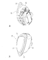
図5は、可動ボタンモジュールを駆動する駆動機構部15の構造を示す分解斜視図である。駆動機構部15は、図5に示すように、駆動演出部15Aと振動モジュール15Bとからなる。駆動演出部15Aは、可動ボタンモジュールを上記ヒンジ部17を中心に上下方向に揺動させるためのアクチュエータとして備えられる。また、振動モジュール15Bには振動モータが搭載されており、該振動モータを駆動させることにより可動ボタンモジュール全体に振動を与えることができる。
FIG. 5 is an exploded perspective view showing the structure of the
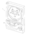
次に、駆動演出部15Aの具体的構成を図6を参照して説明する。駆動演出部15Aは、大略的に、ステッピングモータ(駆動部)150、回転カムプレート(回転部材)151、モジュール開閉リンク(リンク部材)152、モジュール閉保持フック(保持部材)153、バネ154、フック解除レバー(保持解除部材)155およびカムプレート回転位置検出センサ156を備えて構成されている。
Next, a specific configuration of the
ステッピングモータ150は、駆動演出部15Aにおける動力源であり、パルス駆動信号によって所定角度毎の回転が可能である。また、ステッピングモータ150は、正転および逆転の両方の回転駆動が可能なモータである。回転カムプレート151は、ステッピングモータ150によって回転駆動されるものであり、ステッピングモータ150からギア等を介して回転駆動される軸157の両側に配されている。
The stepping
回転カムプレート151は、フランジ部151aとカム部151bとからなり、フランジ部151aには、モジュール開閉リンク152の一端が回転自在に取り付けられている。回転カムプレート151の回転軸(すなわち軸157)およびモジュール開閉リンク152の回転軸152aは、上カバー11のヒンジ部17の軸17a(図3参照)と平行である。フランジ部151aにおけるモジュール開閉リンク152の取付位置は、フランジ部151aの回転中心から半径方向に離れた位置となっている。また、モジュール開閉リンク152の他端には長穴152bが形成されており、長穴152bには上カバー11において固定的に設けられたピン部11c(図7参照)が挿入される。
The rotating
モジュール閉保持フック153は、可動ボタンモジュールを閉状態において保持するものである。モジュール閉保持フック153の一端は駆動演出部15Aのフレーム部15Afに対して回転自在に取り付けられており、他端側の先端は上カバー11に固定的に形成された係合片11d(図7参照)に係合して保持できるフックとなっている。モジュール閉保持フック153の回転軸153aは、上カバー11のヒンジ部17の軸17a(図3参照)と平行である。
The module
バネ154は、モジュール閉保持フック153と駆動演出部15Aが有するフレーム部15Afとの間に配置される引張りバネであり、モジュール閉保持フック153に対して付勢力を与えるものである。すなわち、モジュール閉保持フック153は、バネ154により可動ボタンモジュールを保持する方向(係合片11dとの係合方向)に付勢される。
The
フック解除レバー155は、モジュール閉保持フック153による可動ボタンモジュールの保持を解除するものである。フック解除レバー155の一端は、モジュール閉保持フック153の一端と同じ回転軸153aにおいて、駆動演出部15Aのフレーム部15Afに対して回転自在に取り付けられている。また、フック解除レバー155の他端は、回転カムプレート151のカム部151bと近接して配置され、カム部151bが回転した場合に、カム部151bの外周部に形成された突起部151d(図8参照)に接触して揺動するようになっている。
The
フック解除レバー155が揺動移動する場合、フック解除レバー155はモジュール閉保持フック153に対して一方向にのみ回転力を伝達できるようになっている。具体的には、モジュール閉保持フック153が可動ボタンモジュールの保持を解除する方向にのみ、フック解除レバー155はモジュール閉保持フック153に対して回転力を伝達できる。逆に、モジュール閉保持フック153は、フック解除レバー155に対して、可動ボタンモジュールを保持する方向にのみ回転力を伝達できる。
When the
このような構成は、例えば、モジュール閉保持フック153に設けられた円弧形状の長穴153b(図11参照)と、フック解除レバー155に設けられた係合ピン155a(図11参照)によって得られる。すなわち、フック解除レバー155側の係合ピン155aがモジュール閉保持フック153側の長穴153bに嵌合するように配置される。回転力を伝達する方向では、係合ピン155aが長穴153bの一方の端部に接触し、係合ピン155aと長穴153bとの間で回転力が伝達される。一方、回転力を伝達しない方向では、係合ピン155aが長穴153b内で相対的に移動するのみで、これらの間で回転力は伝達されない。
Such a configuration is obtained by, for example, an arc-shaped
カムプレート回転位置検出センサ156は、回転カムプレート151の回転位置を検出するものであり、例えばフォトセンサによって構成される。回転カムプレート151には、外周縁の一箇所に切欠き151cが設けられている。カムプレート回転位置検出センサ156は、切欠き151cを検出することによって、回転カムプレート151の基準位置を検出できる。また、回転カムプレート151が基準位置からさらに回転駆動された場合には、該駆動のために与えられたパルス駆動信号のパルス数によって、制御部(図示せず)が回転カムプレート151の現在の回転位置(基準位置からの回転量)を認識できるようになっている。
The cam plate rotation
本実施の形態に係る遊技用押しボタンスイッチでは、駆動演出部15Aによって、可動ボタンモジュールの格納動作、可動ボタンモジュールの開放動作、および可動ボタンモジュールの揺動動作が行える。以下、それぞれの動作について説明する。
In the game push button switch according to the present embodiment, the
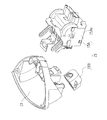
〔可動ボタンモジュールの格納動作〕
可動ボタンモジュールの格納動作について、図7を参照して説明する。
[Storing operation of movable button module]
The storing operation of the movable button module will be described with reference to FIG.
可動ボタンモジュールの格納時には、ステッピングモータ150が回転カムプレート151を回動させ(図7(a)中の矢印方向(反時計回り方向))、モジュール開閉リンク152を介して可動ボタンモジュールを下方に引き下げる。また、上カバー11には、モジュール閉保持フック153のフック部分と係合して可動ボタンモジュールを保持する係合片11dが固定的に形成されている。
When retracting the movable button module, the stepping
上記引き下げ動作によって可動ボタンモジュールが下降する過程で、係合片11dがモジュール閉保持フック153の先端の傾斜面153cに当接し、モジュール閉保持フック153を退避方向(図中の時計回り方向)に回動させる。このとき、モジュール閉保持フック153は、フック解除レバー155に対して回転力を伝達しない。
In the process in which the movable button module is lowered by the lowering operation, the engaging
可動ボタンモジュールがさらに下降すると、図7(b)に示すように、モジュール閉保持フック153がバネ154の付勢力によって係合片11dに係合し、可動ボタンモジュールが閉状態にて保持される。すなわち、可動ボタンモジュールが下ケース13内に格納される。この格納状態は、後述する開放動作が行われるまで保持される。尚、遊技者が手動で可動ボタンモジュールを押し下げる操作によっても、可動ボタンモジュールを格納状態へ移行させることは可能である。
When the movable button module is further lowered, as shown in FIG. 7B, the module
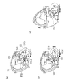
〔可動ボタンモジュールの開放動作〕
可動ボタンモジュールの開放動作について、図8を参照して説明する。
[Opening operation of the movable button module]
The opening operation of the movable button module will be described with reference to FIG.
可動ボタンモジュールの開放時には、ステッピングモータ150によって回転カムプレート151を回転させる(図8(a)中の矢印方向(反時計回り方向))。この間、可動ボタンモジュールは、モジュール閉保持フック153によって閉状態で保持されている。そして、上カバー11に設けられたピン部11cが、モジュール開閉リンク152に設けられた長穴内で相対的に移動する。
When the movable button module is opened, the rotating
回転カムプレート151が図8(a)の状態からさらに回転して図8(b)の状態になると、モジュール閉保持フック153が図中の時計回り方向に回動し、可動ボタンモジュールの保持を解除する。この動作は、回転カムプレート151におけるカム部151bが、フック解除レバー155に作用することによってなされる。すなわち、カム部151bの外周縁に形成された突起部151dがフック解除レバー155の一端(図中右側)に当接し、この状態でカム部151bが反時計回り方向に回転することで、カム部151bがフック解除レバー155の一端を押し下げる。これにより、フック解除レバー155が、図中左側の端部を中心に時計回り方向に回動する。フック解除レバー155の回動はモジュール閉保持フック153に伝達され、モジュール閉保持フック153が可動ボタンモジュールの保持を解除する方向に移動する。
When the rotating
一方、上カバー11は、上述したように付勢部材(例えば、ヒンジ部17に設けられた弦巻バネ)によって上方向に付勢されている。このため、モジュール閉保持フック153による保持が解除されると、図8(c)に示すように、可動ボタンモジュールは上記付勢部材の付勢力によって跳ね上がり、可動ボタンモジュールが開放される。
On the other hand, as described above, the
上記格納動作と上記開放動作とを組み合わせることで、例えば、最下位置まで引き込まれた可動ボタンモジュールがその位置から上方に跳ね上がるといった演出動作を行うことができる。 By combining the storing operation and the opening operation, for example, it is possible to perform an effect operation in which the movable button module drawn to the lowest position jumps upward from the position.
〔可動ボタンモジュールの揺動動作〕
可動ボタンモジュールの開放動作について、図9および図10を参照して説明する。図9は、可動ボタンモジュールの開状態での揺動動作を説明する図である。また、図10は、可動ボタンモジュールの閉状態での揺動動作を説明する図である。
[Oscillating motion of the movable button module]
The opening operation of the movable button module will be described with reference to FIG. 9 and FIG. FIG. 9 is a diagram illustrating the swinging operation in the open state of the movable button module. FIG. 10 is a diagram for explaining the swinging operation in the closed state of the movable button module.
可動ボタンモジュールを開状態で揺動させる場合には、可動ボタンモジュールの開状態からステッピングモータ150に所定パルス数の駆動信号を与え、回転カムプレート151を所定量(例えば、30°程度)回転させる。これに連動して、可動ボタンモジュールが下方にわずかに引き下げられる(図9(a)から図9(b))。
When swinging the movable button module in the open state, a drive signal having a predetermined number of pulses is given to the stepping
さらに、ステッピングモータ150を逆方向に同一量駆動させることで、可動ボタンモジュールが元の位置(開状態位置)に戻る(図9(b)から図9(a))。この動作を繰り返し行うことで、可動ボタンモジュールの開状態での揺動動作を行わせることができる。
Further, by driving the stepping
可動ボタンモジュールを閉状態で揺動させる場合には、可動ボタンモジュールの閉状態からステッピングモータ150に所定パルス数の駆動信号を与え、回転カムプレート151を所定量(例えば、45°程度)回転させる。これに連動して、モジュール閉保持フック153による保持が解除されると共に、可動ボタンモジュールが上方にわずかに開放される(図10(a)から図10(b))。
When the movable button module is swung in the closed state, a drive signal having a predetermined number of pulses is given to the stepping
すなわち、上記動作の間に、カム部151bの外周縁に形成された突起部151e(図11(b)参照)がフック解除レバー155の一端(図中右側)に当接し、フック解除レバー155の一端を押し下げる。このフック解除レバー155の回動がモジュール閉保持フック153に伝達され、モジュール閉保持フック153が可動ボタンモジュールの保持を解除する。可動ボタンモジュールの保持が解除されると、付勢部材(例えば、ヒンジ部17に設けられた弦巻バネ)の復元力により可動ボタンモジュールが上方にわずかに開放される。
That is, during the above operation, the
さらに、ステッピングモータ150を逆方向に同一量駆動させることで、可動ボタンモジュールが元の位置(閉状態位置)に戻る(図10(b)から図10(a))。この動作を繰り返し行うことで、可動ボタンモジュールの閉状態での揺動動作を行わせることができる。
Further, by driving the stepping
上述した開放動作時に保持を解除させるための突起部151dと揺動動作時に保持を解除させるための突起部151eとは、カム部151bの異なる位置に形成されている。このため、図11(a)に示すフック解除動作と図11(b)に示すフック解除動作とでは、フック解除されたときの可動ボタンモジュールの戻り量が異なる。すなわち、図11(a)に示すフック解除動作では、可動ボタンモジュールは開状態に近い位置まで大きく戻り、上述した開放動作を行うことができる。一方、図11(b)に示すフック解除動作では、可動ボタンモジュールの戻り量は小さく、上述した揺動動作を行うことができる。
The
また、突起部151eの形成幅(カム部151bの円周方向に沿った幅)は、突起部151dの形成幅よりも大きく設定されている。これにより、図11(b)に示すフック解除がされている時には、図11(a)に示すフック解除がされている時に比べて、可動ボタンモジュールの戻り速度を遅くすることができる。
Further, the formation width of the
上記例では、可動ボタンモジュールの開状態での揺動動作と閉状態での揺動動作とを説明したが、本発明はこれに限定されるものではない。ステッピングモータ150は、回転カムプレート151の任意の位置で、かつ、任意の回転範囲で正・逆転駆動を繰り返させることが可能であるため、可動ボタンモジュールの任意の開度(例えば、50%程度開放した状態)で揺動動作を行わせることも可能である。
In the above example, the swing operation in the open state and the swing operation in the closed state of the movable button module have been described, but the present invention is not limited to this. Since the stepping
以上のように、本実施の形態に係る押しボタンスイッチ10では、1つのアクチュエータ、すなわち駆動演出部15Aによって、可動ボタンモジュールの格納動作、可動ボタンモジュールの開放動作、および可動ボタンモジュールの揺動動作が行える。すなわち、1つのアクチュエータに多様な演出を実現させ、機器の高額化、重量化および大型化を招くことなく、複雑な演出動作を行うことが可能となる。
As described above, in the
〔遊技者による可動ボタンモジュールの押し下げ動作〕
上記説明では、駆動演出部15Aによって実行できる押しボタンスイッチ10の演出動作について説明したが、押しボタンスイッチ10では、遊技者による可動ボタンモジュールの押し下げ動作によって操作信号を出力させることも可能である。遊技者による可動ボタンモジュールの押し下げ動作について、図12を参照して説明する。
[Pushing action of movable button module by player]
In the above description, the presentation operation of the
押しボタンスイッチ10では、上述した閉状態における可動ボタンモジュールの位置が可動ボタンモジュールの移動可能範囲の下限ではなく、遊技者による押し下げ動作によってさらに下方に移動させることが可能である。
In the
図12(a)は、可動ボタンモジュールが閉状態の位置にある場合を示している。ここで、可動ボタンモジュールの上カバー11には遮光片11eが固定的に設けられている。一方、可動ボタンモジュール位置検出用センサ16が、下ケース13に対して固定的に取り付けられている。
FIG. 12A shows the case where the movable button module is in the closed position. Here, a
可動ボタンモジュール位置検出用センサ16は、例えば、受光素子と発光素子とを対向配置してなるフォトマイクロセンサであり、受光素子と発光素子との間に障害物がなく、受光素子が発光素子からの光を受光している間はオフ信号を出力する。受光素子と発光素子との間に障害物があり、受光素子が発光素子からの光を受光できなくなると、可動ボタンモジュール位置検出用センサ16はオン信号を出力する。
The movable button module
図12(a)に示すように、可動ボタンモジュールが閉状態であるとき、上カバー11の遮光片11eは、可動ボタンモジュール位置検出用センサ16の近傍にはあるものの、遮光片11eが受光素子と発光素子との間には入り込まない。このため、可動ボタンモジュール位置検出用センサ16はオフ信号を出力する。
As shown in FIG. 12A, when the movable button module is in the closed state, the
可動ボタンモジュールが遊技者によって押し下げられ、図12(c)に示す状態となると、遮光片11eは、受光素子と発光素子との間に入り込む。これにより、受光素子が発光素子からの光を受光できなくなり、可動ボタンモジュール位置検出用センサ16はオン信号を出力する。
When the movable button module is pushed down by the player and enters the state shown in FIG. 12C, the
遊技者による可動ボタンモジュールの押し下げ動作がなされ、可動ボタンモジュール位置検出用センサ16がオン信号を出力した場合は、該オン信号はパチンコ機1の制御部によって検出される。制御部は、上記オン信号を検出した場合に、パチンコ機1の演出動作に変化を与えたり、あるいは、振動モジュール15Bを動作させて可動ボタンモジュール全体に振動を与えたりすることができる。但し、可動ボタンモジュール位置検出用センサ16によるオン信号(遊技者によるボタン操作検知)をどのように用いるかは、本発明において特に限定されるものではない。
When the player pushes down the movable button module and the movable button module
尚、遊技者による可動ボタンモジュールの押し下げ動作は、図12(a)に示す可動ボタンモジュールの閉状態からのみならず、図12(b)に示す可動ボタンモジュールの開状態から行われても良い。 Note that the pressing operation of the movable button module by the player may be performed not only from the closed state of the movable button module shown in FIG. 12A but also from the open state of the movable button module shown in FIG. .
本発明は、その思想または主要な特徴から逸脱することなく、他のいろいろな形で実施することができる。そのため、上述の実施例はあらゆる点で単なる例示にすぎず、限定的に解釈してはならない。本発明の範囲は特許請求の範囲によって示すものであって、明細書本文には、なんら拘束されない。さらに、特許請求の範囲の均等範囲に属する変形や変更は、全て本発明の範囲内のものである。 The present invention can be implemented in various other forms without departing from the spirit or main features thereof. For this reason, the above-described embodiment is merely an example in all respects and should not be interpreted in a limited manner. The scope of the present invention is indicated by the claims, and is not restricted by the text of the specification. Further, all modifications and changes belonging to the equivalent scope of the claims are within the scope of the present invention.
1 パチンコ機(遊技機)
10 押しボタンスイッチ(外部演出動作機構)
11 上カバー(可動ボタンモジュール)
11d 係合片
11e 遮光片
12 ベゼル(取付部)
13 下ケース(取付部)
14 光演出部(可動ボタンモジュール)
15 駆動機構部
17 ヒンジ部
15A 駆動演出部(アクチュエータ)
150 ステッピングモータ(駆動部、モータ)
151 回転カムプレート(回転部材)
151a フランジ部
151b カム部
152 モジュール開閉リンク(リンク部材)
153 モジュール閉保持フック(保持部材)
154 バネ
155 フック解除レバー(保持解除部材)
156 カムプレート回転位置検出センサ
16 可動ボタンモジュール位置検出用センサ
1 Pachinko machine (game machine)
10 Pushbutton switch (external production mechanism)
11 Upper cover (movable button module)
13 Lower case (mounting part)
14 Light production section (movable button module)
15
150 Stepping motor (drive unit, motor)
151 Rotating cam plate (Rotating member)
153 Module closed holding hook (holding member)
154
156 Cam plate rotation
Claims (6)
該押しボタンスイッチを前記遊技機に対して固定的に取り付けるための取付部と、
前記取付部に対してヒンジ部にて結合されており、該ヒンジ部を中心に上下方向に回動可能となっている可動ボタンモジュールと、
駆動部を備え、前記可動ボタンモジュールに前記上下方向の回動駆動力を与えることが可能なアクチュエータとを有していることを特徴とする押しボタンスイッチ。 A push button switch used in a gaming machine,
A mounting portion for fixedly mounting the push button switch to the gaming machine;
A movable button module that is coupled to the mounting portion at a hinge portion, and is rotatable in the vertical direction around the hinge portion;
A push button switch comprising: a drive unit; and an actuator capable of applying the vertical driving force to the movable button module.
前記アクチュエータは、前記駆動部として正転および逆転の両方の回転駆動が可能なモータを備えており、
前記アクチュエータは、正転および逆転駆動を繰り返すことにより、前記可動ボタンモジュールに対して任意の位置で上下運動を繰り返す揺動運動を行わせることが可能であることを特徴とする押しボタンスイッチ。 The push button switch according to claim 1,
The actuator includes a motor capable of both forward rotation and reverse rotation as the drive unit,
The actuator is capable of causing the movable button module to perform a swinging motion that repeats a vertical motion at an arbitrary position by repeating forward and reverse driving.
前記可動ボタンモジュールは、上方向に回動させる付勢力を与えられながら前記取付部に取り付けられているものであり、
前記アクチュエータは、
前記駆動部の駆動力を受けて回転する回転部材と、
前記回転部材と前記可動ボタンモジュールとを連結するものであり、前記回転部材の回転によって前記可動ボタンモジュールを下方向へ引き込むことが可能なリンク部材と、
前記回転部材および前記リンク部材により前記可動ボタンモジュールが最下位置に来た場合に、前記可動ボタンモジュールを最下位置で保持可能な保持部材と、
前記回転部材が所定の回転位置に来た場合に、前記保持部材による前記可動ボタンモジュールの保持を解除する保持解除部材とを備えていることを特徴とする押しボタンスイッチ。 The push button switch according to claim 1 or 2,
The movable button module is attached to the attachment portion while being given an urging force to rotate upward.
The actuator is
A rotating member that rotates in response to the driving force of the driving unit;
Linking the rotating member and the movable button module, a link member capable of pulling the movable button module downward by rotation of the rotating member;
A holding member capable of holding the movable button module at the lowest position when the movable button module is at the lowest position by the rotating member and the link member;
A push button switch, comprising: a holding release member that releases the holding of the movable button module by the holding member when the rotating member comes to a predetermined rotation position.
該外部演出動作機構を前記遊技機に対して固定的に取り付けるための取付部と、
前記取付部に対してヒンジ結合されており、該ヒンジ部を中心に上下方向に回動可能となっている可動モジュールと、
駆動部を備え、前記可動モジュールに前記上下方向の回動駆動力を与えることが可能なアクチュエータとを有していることを特徴とする外部演出動作機構。 An external performance operation mechanism used in a gaming machine,
An attachment portion for fixedly attaching the external performance operation mechanism to the gaming machine;
A movable module that is hinge-coupled to the mounting portion and is rotatable in the vertical direction around the hinge portion;
An external rendering operation mechanism, comprising: an actuator that includes a drive unit and is capable of applying the vertical driving force to the movable module.
Priority Applications (1)
| Application Number | Priority Date | Filing Date | Title |
|---|---|---|---|
| JP2015120149A JP2017000598A (en) | 2015-06-15 | 2015-06-15 | Push button switch, external performance operation mechanism, and game machine |
Applications Claiming Priority (1)
| Application Number | Priority Date | Filing Date | Title |
|---|---|---|---|
| JP2015120149A JP2017000598A (en) | 2015-06-15 | 2015-06-15 | Push button switch, external performance operation mechanism, and game machine |
Publications (1)
| Publication Number | Publication Date |
|---|---|
| JP2017000598A true JP2017000598A (en) | 2017-01-05 |
Family
ID=57750995
Family Applications (1)
| Application Number | Title | Priority Date | Filing Date |
|---|---|---|---|
| JP2015120149A Pending JP2017000598A (en) | 2015-06-15 | 2015-06-15 | Push button switch, external performance operation mechanism, and game machine |
Country Status (1)
| Country | Link |
|---|---|
| JP (1) | JP2017000598A (en) |
Citations (3)
| Publication number | Priority date | Publication date | Assignee | Title |
|---|---|---|---|---|
| JP2005323748A (en) * | 2004-05-13 | 2005-11-24 | Fujishoji Co Ltd | Game machine |
| JP2006075224A (en) * | 2004-09-07 | 2006-03-23 | Adachi Light Co Ltd | Game machine |
| JP2016209525A (en) * | 2015-04-30 | 2016-12-15 | 株式会社三洋物産 | Game machine |
-
2015
- 2015-06-15 JP JP2015120149A patent/JP2017000598A/en active Pending
Patent Citations (3)
| Publication number | Priority date | Publication date | Assignee | Title |
|---|---|---|---|---|
| JP2005323748A (en) * | 2004-05-13 | 2005-11-24 | Fujishoji Co Ltd | Game machine |
| JP2006075224A (en) * | 2004-09-07 | 2006-03-23 | Adachi Light Co Ltd | Game machine |
| JP2016209525A (en) * | 2015-04-30 | 2016-12-15 | 株式会社三洋物産 | Game machine |
Similar Documents
| Publication | Publication Date | Title |
|---|---|---|
| JP4887416B2 (en) | Decoration body unit, game board unit, and pachinko machine | |
| JP4717024B2 (en) | Mechanical presentation device for pachinko machines | |
| JP5722274B2 (en) | Game machine | |
| JP5140511B2 (en) | Decorative body drive unit, presentation device, game board, and pachinko machine | |
| JP4912078B2 (en) | Decorative body swing unit | |
| JP2012081020A (en) | Movable presentation device of game machine | |
| JP4749436B2 (en) | Lighting device, game board, and pachinko machine | |
| JP2012105806A (en) | Game machine | |
| JP6034247B2 (en) | Game machine | |
| JP5133437B2 (en) | Pachinko machine | |
| JP2013212301A (en) | Game machine | |
| JP2013226313A (en) | Game machine | |
| JP5292385B2 (en) | Pachinko machine | |
| JP6409631B2 (en) | Production operation device for gaming machines | |
| JP2017000598A (en) | Push button switch, external performance operation mechanism, and game machine | |
| JP5786231B2 (en) | Game machine | |
| JP5763008B2 (en) | Game machine | |
| JP4342925B2 (en) | Game machine | |
| JP2012100958A (en) | Game machine | |
| JP5659383B2 (en) | Game machine | |
| JP5049370B2 (en) | Light emitting unit | |
| JP6086354B2 (en) | Game machine | |
| JP5531145B2 (en) | Game machine | |
| JP2012100732A (en) | Game machine | |
| JP6869564B2 (en) | Game machine |
Legal Events
| Date | Code | Title | Description |
|---|---|---|---|
| A621 | Written request for application examination |
Free format text: JAPANESE INTERMEDIATE CODE: A621 Effective date: 20180412 |
|
| A131 | Notification of reasons for refusal |
Free format text: JAPANESE INTERMEDIATE CODE: A131 Effective date: 20181204 |
|
| A977 | Report on retrieval |
Free format text: JAPANESE INTERMEDIATE CODE: A971007 Effective date: 20181207 |
|
| A02 | Decision of refusal |
Free format text: JAPANESE INTERMEDIATE CODE: A02 Effective date: 20190604 |