JP2016539865A - Packaged oral care device and method for opening it - Google Patents
Packaged oral care device and method for opening it Download PDFInfo
- Publication number
- JP2016539865A JP2016539865A JP2016527345A JP2016527345A JP2016539865A JP 2016539865 A JP2016539865 A JP 2016539865A JP 2016527345 A JP2016527345 A JP 2016527345A JP 2016527345 A JP2016527345 A JP 2016527345A JP 2016539865 A JP2016539865 A JP 2016539865A
- Authority
- JP
- Japan
- Prior art keywords
- tab
- panel
- oral care
- care device
- packaged
- Prior art date
- Legal status (The legal status is an assumption and is not a legal conclusion. Google has not performed a legal analysis and makes no representation as to the accuracy of the status listed.)
- Pending
Links
Images


Classifications
-
- B—PERFORMING OPERATIONS; TRANSPORTING
- B65—CONVEYING; PACKING; STORING; HANDLING THIN OR FILAMENTARY MATERIAL
- B65D—CONTAINERS FOR STORAGE OR TRANSPORT OF ARTICLES OR MATERIALS, e.g. BAGS, BARRELS, BOTTLES, BOXES, CANS, CARTONS, CRATES, DRUMS, JARS, TANKS, HOPPERS, FORWARDING CONTAINERS; ACCESSORIES, CLOSURES, OR FITTINGS THEREFOR; PACKAGING ELEMENTS; PACKAGES
- B65D75/00—Packages comprising articles or materials partially or wholly enclosed in strips, sheets, blanks, tubes, or webs of flexible sheet material, e.g. in folded wrappers
- B65D75/52—Details
- B65D75/58—Opening or contents-removing devices added or incorporated during package manufacture
- B65D75/5827—Tear-lines provided in a wall portion
- B65D75/5833—Tear-lines provided in a wall portion for tearing out a portion of the wall
- B65D75/5844—Tear-lines provided in a wall portion for tearing out a portion of the wall the portion of the wall being a narrow strip, e.g. between lines of weakness
-
- B—PERFORMING OPERATIONS; TRANSPORTING
- B65—CONVEYING; PACKING; STORING; HANDLING THIN OR FILAMENTARY MATERIAL
- B65D—CONTAINERS FOR STORAGE OR TRANSPORT OF ARTICLES OR MATERIALS, e.g. BAGS, BARRELS, BOTTLES, BOXES, CANS, CARTONS, CRATES, DRUMS, JARS, TANKS, HOPPERS, FORWARDING CONTAINERS; ACCESSORIES, CLOSURES, OR FITTINGS THEREFOR; PACKAGING ELEMENTS; PACKAGES
- B65D75/00—Packages comprising articles or materials partially or wholly enclosed in strips, sheets, blanks, tubes, or webs of flexible sheet material, e.g. in folded wrappers
- B65D75/28—Articles or materials wholly enclosed in composite wrappers, i.e. wrappers formed by associating or interconnecting two or more sheets or blanks
- B65D75/30—Articles or materials enclosed between two opposed sheets or blanks having their margins united, e.g. by pressure-sensitive adhesive, crimping, heat-sealing, or welding
- B65D75/32—Articles or materials enclosed between two opposed sheets or blanks having their margins united, e.g. by pressure-sensitive adhesive, crimping, heat-sealing, or welding one or both sheets or blanks being recessed to accommodate contents
- B65D75/325—Articles or materials enclosed between two opposed sheets or blanks having their margins united, e.g. by pressure-sensitive adhesive, crimping, heat-sealing, or welding one or both sheets or blanks being recessed to accommodate contents one sheet being recessed, and the other being a flat not- rigid sheet, e.g. puncturable or peelable foil
- B65D75/326—Articles or materials enclosed between two opposed sheets or blanks having their margins united, e.g. by pressure-sensitive adhesive, crimping, heat-sealing, or welding one or both sheets or blanks being recessed to accommodate contents one sheet being recessed, and the other being a flat not- rigid sheet, e.g. puncturable or peelable foil and forming one compartment
-
- A—HUMAN NECESSITIES
- A46—BRUSHWARE
- A46B—BRUSHES
- A46B15/00—Other brushes; Brushes with additional arrangements
-
- B—PERFORMING OPERATIONS; TRANSPORTING
- B65—CONVEYING; PACKING; STORING; HANDLING THIN OR FILAMENTARY MATERIAL
- B65D—CONTAINERS FOR STORAGE OR TRANSPORT OF ARTICLES OR MATERIALS, e.g. BAGS, BARRELS, BOTTLES, BOXES, CANS, CARTONS, CRATES, DRUMS, JARS, TANKS, HOPPERS, FORWARDING CONTAINERS; ACCESSORIES, CLOSURES, OR FITTINGS THEREFOR; PACKAGING ELEMENTS; PACKAGES
- B65D75/00—Packages comprising articles or materials partially or wholly enclosed in strips, sheets, blanks, tubes, or webs of flexible sheet material, e.g. in folded wrappers
- B65D75/28—Articles or materials wholly enclosed in composite wrappers, i.e. wrappers formed by associating or interconnecting two or more sheets or blanks
- B65D75/30—Articles or materials enclosed between two opposed sheets or blanks having their margins united, e.g. by pressure-sensitive adhesive, crimping, heat-sealing, or welding
- B65D75/32—Articles or materials enclosed between two opposed sheets or blanks having their margins united, e.g. by pressure-sensitive adhesive, crimping, heat-sealing, or welding one or both sheets or blanks being recessed to accommodate contents
- B65D75/325—Articles or materials enclosed between two opposed sheets or blanks having their margins united, e.g. by pressure-sensitive adhesive, crimping, heat-sealing, or welding one or both sheets or blanks being recessed to accommodate contents one sheet being recessed, and the other being a flat not- rigid sheet, e.g. puncturable or peelable foil
- B65D75/327—Articles or materials enclosed between two opposed sheets or blanks having their margins united, e.g. by pressure-sensitive adhesive, crimping, heat-sealing, or welding one or both sheets or blanks being recessed to accommodate contents one sheet being recessed, and the other being a flat not- rigid sheet, e.g. puncturable or peelable foil and forming several compartments
- B65D75/328—Articles or materials enclosed between two opposed sheets or blanks having their margins united, e.g. by pressure-sensitive adhesive, crimping, heat-sealing, or welding one or both sheets or blanks being recessed to accommodate contents one sheet being recessed, and the other being a flat not- rigid sheet, e.g. puncturable or peelable foil and forming several compartments the compartments being interconnected, e.g. by small channels
-
- B—PERFORMING OPERATIONS; TRANSPORTING
- B65—CONVEYING; PACKING; STORING; HANDLING THIN OR FILAMENTARY MATERIAL
- B65D—CONTAINERS FOR STORAGE OR TRANSPORT OF ARTICLES OR MATERIALS, e.g. BAGS, BARRELS, BOTTLES, BOXES, CANS, CARTONS, CRATES, DRUMS, JARS, TANKS, HOPPERS, FORWARDING CONTAINERS; ACCESSORIES, CLOSURES, OR FITTINGS THEREFOR; PACKAGING ELEMENTS; PACKAGES
- B65D75/00—Packages comprising articles or materials partially or wholly enclosed in strips, sheets, blanks, tubes, or webs of flexible sheet material, e.g. in folded wrappers
- B65D75/28—Articles or materials wholly enclosed in composite wrappers, i.e. wrappers formed by associating or interconnecting two or more sheets or blanks
- B65D75/30—Articles or materials enclosed between two opposed sheets or blanks having their margins united, e.g. by pressure-sensitive adhesive, crimping, heat-sealing, or welding
- B65D75/32—Articles or materials enclosed between two opposed sheets or blanks having their margins united, e.g. by pressure-sensitive adhesive, crimping, heat-sealing, or welding one or both sheets or blanks being recessed to accommodate contents
- B65D75/36—Articles or materials enclosed between two opposed sheets or blanks having their margins united, e.g. by pressure-sensitive adhesive, crimping, heat-sealing, or welding one or both sheets or blanks being recessed to accommodate contents one sheet or blank being recessed and the other formed of relatively stiff flat sheet material, e.g. blister packages, the recess or recesses being preformed
- B65D75/366—Articles or materials enclosed between two opposed sheets or blanks having their margins united, e.g. by pressure-sensitive adhesive, crimping, heat-sealing, or welding one or both sheets or blanks being recessed to accommodate contents one sheet or blank being recessed and the other formed of relatively stiff flat sheet material, e.g. blister packages, the recess or recesses being preformed and forming one compartment
-
- B—PERFORMING OPERATIONS; TRANSPORTING
- B65—CONVEYING; PACKING; STORING; HANDLING THIN OR FILAMENTARY MATERIAL
- B65D—CONTAINERS FOR STORAGE OR TRANSPORT OF ARTICLES OR MATERIALS, e.g. BAGS, BARRELS, BOTTLES, BOXES, CANS, CARTONS, CRATES, DRUMS, JARS, TANKS, HOPPERS, FORWARDING CONTAINERS; ACCESSORIES, CLOSURES, OR FITTINGS THEREFOR; PACKAGING ELEMENTS; PACKAGES
- B65D75/00—Packages comprising articles or materials partially or wholly enclosed in strips, sheets, blanks, tubes, or webs of flexible sheet material, e.g. in folded wrappers
- B65D75/28—Articles or materials wholly enclosed in composite wrappers, i.e. wrappers formed by associating or interconnecting two or more sheets or blanks
- B65D75/30—Articles or materials enclosed between two opposed sheets or blanks having their margins united, e.g. by pressure-sensitive adhesive, crimping, heat-sealing, or welding
- B65D75/32—Articles or materials enclosed between two opposed sheets or blanks having their margins united, e.g. by pressure-sensitive adhesive, crimping, heat-sealing, or welding one or both sheets or blanks being recessed to accommodate contents
- B65D75/36—Articles or materials enclosed between two opposed sheets or blanks having their margins united, e.g. by pressure-sensitive adhesive, crimping, heat-sealing, or welding one or both sheets or blanks being recessed to accommodate contents one sheet or blank being recessed and the other formed of relatively stiff flat sheet material, e.g. blister packages, the recess or recesses being preformed
- B65D75/367—Articles or materials enclosed between two opposed sheets or blanks having their margins united, e.g. by pressure-sensitive adhesive, crimping, heat-sealing, or welding one or both sheets or blanks being recessed to accommodate contents one sheet or blank being recessed and the other formed of relatively stiff flat sheet material, e.g. blister packages, the recess or recesses being preformed and forming several compartments
- B65D75/368—Articles or materials enclosed between two opposed sheets or blanks having their margins united, e.g. by pressure-sensitive adhesive, crimping, heat-sealing, or welding one or both sheets or blanks being recessed to accommodate contents one sheet or blank being recessed and the other formed of relatively stiff flat sheet material, e.g. blister packages, the recess or recesses being preformed and forming several compartments the compartments being interconnected, e.g. by small channels
-
- B—PERFORMING OPERATIONS; TRANSPORTING
- B65—CONVEYING; PACKING; STORING; HANDLING THIN OR FILAMENTARY MATERIAL
- B65D—CONTAINERS FOR STORAGE OR TRANSPORT OF ARTICLES OR MATERIALS, e.g. BAGS, BARRELS, BOTTLES, BOXES, CANS, CARTONS, CRATES, DRUMS, JARS, TANKS, HOPPERS, FORWARDING CONTAINERS; ACCESSORIES, CLOSURES, OR FITTINGS THEREFOR; PACKAGING ELEMENTS; PACKAGES
- B65D2575/00—Packages comprising articles or materials partially or wholly enclosed in strips, sheets, blanks, tubes or webs of flexible sheet material, e.g. in folded wrappers
- B65D2575/28—Articles or materials wholly enclosed in composite wrappers, i.e. wrappers formed by association or interconnecting two or more sheets or blanks
- B65D2575/30—Articles or materials enclosed between two opposed sheets or blanks having their margins united, e.g. by pressure-sensitive adhesive, crimping, heat-sealing, or welding
- B65D2575/32—Articles or materials enclosed between two opposed sheets or blanks having their margins united, e.g. by pressure-sensitive adhesive, crimping, heat-sealing, or welding one or both sheets or blanks being recessed to accommodate contents
- B65D2575/3209—Details
- B65D2575/3218—Details with special means for gaining access to the contents
- B65D2575/3227—Cuts or weakening lines
- B65D2575/3236—Cuts or weakening lines for initiating or facilitating subsequent peeling off of the non-rigid sheet
-
- B—PERFORMING OPERATIONS; TRANSPORTING
- B65—CONVEYING; PACKING; STORING; HANDLING THIN OR FILAMENTARY MATERIAL
- B65D—CONTAINERS FOR STORAGE OR TRANSPORT OF ARTICLES OR MATERIALS, e.g. BAGS, BARRELS, BOTTLES, BOXES, CANS, CARTONS, CRATES, DRUMS, JARS, TANKS, HOPPERS, FORWARDING CONTAINERS; ACCESSORIES, CLOSURES, OR FITTINGS THEREFOR; PACKAGING ELEMENTS; PACKAGES
- B65D2575/00—Packages comprising articles or materials partially or wholly enclosed in strips, sheets, blanks, tubes or webs of flexible sheet material, e.g. in folded wrappers
- B65D2575/28—Articles or materials wholly enclosed in composite wrappers, i.e. wrappers formed by association or interconnecting two or more sheets or blanks
- B65D2575/30—Articles or materials enclosed between two opposed sheets or blanks having their margins united, e.g. by pressure-sensitive adhesive, crimping, heat-sealing, or welding
- B65D2575/36—One sheet or blank being recessed and the other formed or relatively stiff flat sheet material, e.g. blister packages
- B65D2575/361—Details
- B65D2575/362—Details with special means for gaining access to the contents
- B65D2575/367—Details with special means for gaining access to the contents through a preformed opening in the flat sheet, e.g. the opening being defined by weakened lines
Abstract
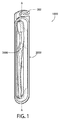
パッケージ化された口腔ケア用具(1000)及びそれを開封する方法。一実施形態において、パッケージ(2000)は、口腔ケア用具自体(1000)が第1のパネルを剪断して、タブを解放することを補助する、タブに隣接する基盤または障壁としての役割を果たすように戦略的に位置する、パッケージの第1のパネル(100)上のタブ(106)を含む。【選択図】図1Packaged oral care device (1000) and method of opening it. In one embodiment, the package (2000) serves as a base or barrier adjacent to the tab that helps the oral care device itself (1000) shear the first panel to release the tab. Includes a tab (106) on the first panel (100) of the package, strategically located in FIG. [Selection] Figure 1
Description
歯ブラシなどの口腔ケア用具の商品化において、現在の傾向は、該口腔ケア用具を密封されたパッケージに入れて販売することである。そのようなパッケージの設計において、以下の目標、つまり、不正開封防止、製品及びマーケティング情報の視感度、口腔ケア用具を保護するための構造的安定性、ならびに開封の容易さがしばしば追求される。しばしば、これらの目標は競合するため、バランスが取られなくてはならない。したがって、上述の目標のうちの1つ以上をより適切に達成する、及び/またはそれらのバランスを取る、改善されたパッケージ化された口腔ケア用具に対する必要性が存在する。 In the commercialization of oral care devices such as toothbrushes, the current trend is to sell the oral care device in a sealed package. In designing such packages, the following goals are often pursued: tamper-evident prevention, visibility of product and marketing information, structural stability to protect oral care devices, and ease of opening. Often these goals are competing and must be balanced. Accordingly, there is a need for an improved packaged oral care device that better achieves and / or balances one or more of the above goals.
一態様において、本発明はパッケージ化された口腔ケア用具を対象とし、それを開封する方法は、任意で、タブが口腔ケア用具を保持する空洞内に実質的に妨害されない様式で偏向されることを可能にしながら、口腔ケア用具自体が第1のパネルを剪断して、把持するためにタブを解放することを補助する、タブに隣接する基盤としての役割を果たすように戦略的に位置するパッケージの第1のパネルのうちの1つの上のタブを含む。別の態様において、本発明は、パッケージの内部構成要素の検出不能な不正開封を同時に防止しながら、標的化された容易な開封位置が提供されるように、予脆弱化線を含むパッケージの第1のパネルが、異なる非ゼロ剪断強度の少なくとも2つの部分を含むことを含む、パッケージ化された口腔ケア用具及びそれを開封する方法を対象とし得る。 In one aspect, the present invention is directed to a packaged oral care device, and the method of opening it is optionally deflected in a manner that is not substantially disturbed within the cavity holding the oral care device. Strategically positioned package to serve as a base adjacent to the tab, helping the oral care device itself shear the first panel and release the tab for grasping while allowing Including a tab on one of the first panels. In another aspect, the present invention is directed to a package including a pre-weakening line so that a targeted easy opening position is provided while simultaneously preventing undetectable tampering of the package's internal components. It may be directed to a packaged oral care device and method for opening it, wherein one panel includes at least two portions of different non-zero shear strength.
一実施形態において、本発明は、第1のパネル及び第2のパネル、第1のパネルと第2のパネルとの間に形成された空洞を備え、第1のパネルが、引き剥がし部分及び基部部分を画定する、少なくとも1つの予脆弱化線を含み、基部部分が、第2のパネルに連結され、基部部分が、引き剥がし部分内に突出するタブを備え、タブが、予脆弱化線の第1の部分によって画定され、更に、空洞内に位置付けられた口腔ケア用具であって、その一部分が、タブに隣接する引き剥がし部分の第1の部分の下に置かれるように位置付けられ、タブが、空洞の非占有部分上に位置する、口腔ケア用具を備え、タブが、タブに適用される下向きの力に応答して、(1)予脆弱化線の第1の部分がそのままである閉鎖状態、及び(2)予脆弱化線の第1の部分が剪断され、タブが口腔ケア用具の部分の上表面の下の深さまで非占有部分内に偏向される開封状態、から変更可能である、パッケージ化された口腔ケア用具であり得る。 In one embodiment, the present invention comprises a first panel and a second panel, a cavity formed between the first panel and the second panel, wherein the first panel comprises a peel-off portion and a base. At least one pre-weakening line defining a portion, the base portion being coupled to the second panel, the base portion comprising a tab projecting into the peel-off portion, wherein the tab comprises a pre-weakening line An oral care device defined by a first portion and positioned within the cavity, wherein a portion of the oral care device is positioned to be placed under the first portion of the tear-off portion adjacent to the tab. Comprises an oral care device located on the unoccupied portion of the cavity, wherein the tab is responsive to the downward force applied to the tab, (1) the first portion of the pre-weakening line remains intact Closed state, and (2) the first part of the pre-weakening line Sheared, the tab can be changed from the opened state, to be deflected into the unoccupied portion to a depth below the upper surface portion of the oral care implement may be packaged oral care implement.
別の実施形態において、本発明は、第1のパネル及び第2のパネル、第1のパネルと第2のパネルとの間に形成される空洞を備え、第1のパネルが、引き剥がし部分及び基部部分を画定する、少なくとも1つの予脆弱化線を含み、基部部分が、第2のパネルに連結され、基部部分が、引き剥がし部分内に突出するタブを備え、タブが、予脆弱化線の第1の部分によって画定され、更に、空洞内に位置付けられた口腔ケア用具であって、その一部分が、タブに隣接する引き剥がし部分の第1の部分の下に置かれるように位置付けられ、タブが、空洞の非占有部分上に位置する、口腔ケア用具を備える、パッケージ化された口腔ケア用具であり得る。 In another embodiment, the present invention comprises a first panel and a second panel, a cavity formed between the first panel and the second panel, the first panel comprising a peel-off portion and At least one pre-weakening line defining a base portion, the base portion being connected to the second panel, the base portion comprising a tab projecting into the peel-off portion, the tab being a pre-weakening line An oral care device defined by the first portion of the device and positioned within the cavity, wherein a portion of the oral care device is positioned to be placed under the first portion of the tear-off portion adjacent to the tab, The tab can be a packaged oral care device comprising an oral care device located on an unoccupied portion of the cavity.
更に別の実施形態において、本発明は、パッケージの空洞内に配設される製品を提供することであって、パッケージが、第1のパネルと、第2のパネルと、第1のパネルと第2のパネルとの間に形成される空洞とを備え、第1のパネルが、引き剥がし部分及び基部部分を画定する、少なくとも1つの予脆弱化線を含み、基部部分が、第2のパネルに連結され、基部部分が引き剥がし部分内に突出するタブを備え、タブが予脆弱化線の第1の部分によって画定され、製品の一部分が、空洞の非占有部分上に位置するタブに隣接する引き剥がし部分の第1の部分の下に置かれるように、製品が空洞内に位置付けられる、提供することと、下向きの力をタブ上に適用して、引き剥がし部分の第1の部分が製品の部分に接触し、予脆弱化線の第1の部分を剪断して、タブを解放させることであって、タブが製品の部分の上表面の下の深さまで非占有部分内に偏向され、これにより第1のパネル内に開口部を形成する、解放させることと、開口部を介して引き剥がし部分を把持し、引き剥がし部分を基部部分から少なくとも部分的に分離させて、製品への到達を提供することと、を含むパッケージ化された製品を開封する方法であり得る。 In yet another embodiment, the present invention provides a product disposed within a cavity of a package, the package comprising a first panel, a second panel, a first panel, and a first panel. The first panel includes at least one pre-weakening line defining a tear-off portion and a base portion, the base portion being in the second panel Connected, the base portion comprises a tab projecting into the tear-off portion, the tab is defined by a first portion of the pre-weakening line, and a portion of the product is adjacent to the tab located on the unoccupied portion of the cavity The product is positioned in the cavity so that it is placed under the first part of the tear-off part, and a downward force is applied on the tab so that the first part of the peel-off part is the product The first part of the pre-weakening line To release the tab, wherein the tab is deflected into the unoccupied portion to a depth below the upper surface of the product portion, thereby forming an opening in the first panel. Opening the packaged product comprising: and holding the peeled portion through the opening, and at least partially separating the peeled portion from the base portion to provide access to the product. Can be a way to do.
更なる一態様において、本発明は、第1のパネル及び第2のパネル、第1のパネルと第2のパネルとの間に形成される空洞を備え、第1のパネルが、引き剥がし部分及び基部部分を画定する、少なくとも1つの予脆弱化線を含み、基部部分が、第2のパネルに連結され、空洞内に位置付けられた口腔ケア用具と、第1の非ゼロ剪断強度を有する第1の予脆弱化パターンを有する第1の部分、及び第1の非ゼロ剪断強度よりも大きい第2の非ゼロ剪断強度を有する第2の予脆弱化パターンを有する第2の部分を含む予脆弱化線と、を備えるパッケージ化された口腔ケア用具であり得る。 In a further aspect, the present invention comprises a first panel and a second panel, a cavity formed between the first panel and the second panel, wherein the first panel comprises a peeling portion and An oral care device including at least one pre-weakening line defining a base portion, the base portion coupled to the second panel and positioned within the cavity, and a first having a first non-zero shear strength A first portion having a pre-weakening pattern and a second portion having a second pre-weakening pattern having a second non-zero shear strength greater than the first non-zero shear strength. A packaged oral care device comprising a wire.
また更なる一態様において、本発明は、パッケージの空洞内に配設される口腔ケア用具を提供することであって、パッケージが、第1のパネルと、第2のパネルと、第1のパネルと第2のパネルとの間に形成される空洞とを備え、第1のパネルが、引き剥がし部分及び基部部分を画定する、少なくとも1つの予脆弱化線を含み、予脆弱化線が、第1の非ゼロ剪断強度を有する第1の予脆弱化パターンを有する第1の部分、及び第1の非ゼロ剪断強度よりも大きい第2の非ゼロ剪断強度を有する第2の予脆弱化パターンを有する第2の部分を含む、提供することと、予脆弱化線の第1の部分に隣接する基部部分上の位置で下向きの力を適用して、予脆弱化線の第1の部分を剪断し、引き剥がし部分の下の基部部分の一部分を偏向されて、第1のパネル内に開口部を形成することと、開口部を介して引き剥がし部分を把持し、引き剥がし部分を基部部分から少なくとも部分的に分離させて、口腔ケア用具への到達を提供することと、を含むパッケージ化された口腔ケア用具を開封する方法であり得る。 In yet a further aspect, the present invention provides an oral care device disposed within a cavity of a package, the package comprising a first panel, a second panel, and a first panel. And a cavity formed between the first panel and the second panel, the first panel including at least one pre-weakening line defining a tear-off portion and a base portion, A first portion having a first pre-weakening pattern having a non-zero shear strength of 1 and a second pre-weakening pattern having a second non-zero shear strength greater than the first non-zero shear strength. Applying and applying a downward force at a location on the base portion adjacent to the first portion of the pre-weakening line to shear the first portion of the pre-weakening line. And deflecting a portion of the base portion under the peel-off portion to Forming an opening in the channel; gripping the peeled portion through the opening; and separating the peeled portion at least partially from the base portion to provide access to the oral care device; A packaged oral care device comprising:
本発明の適用可能性の更なる領域は、下に提供される詳細な記述から明らかになるであろう。詳細な記述及び具体的な実施例は本発明の好ましい実施形態を示す一方で、説明の目的のみが意図され、本発明の範囲を限定することは意図されないことが理解されるべきである。 Further areas of applicability of the present invention will become apparent from the detailed description provided below. It should be understood that while the detailed description and specific examples illustrate preferred embodiments of the present invention, they are intended for purposes of illustration only and are not intended to limit the scope of the invention.
本発明は、詳細な記述及び添付の図面からより完全に理解されるであろう。 The present invention will become more fully understood from the detailed description and the accompanying drawings, wherein:
好ましい実施形態(複数可)についての以下の記述は、その性質において例示的であるにすぎず、本発明、その出願、または使用を限定することは決して意図されない。 The following description of preferred embodiment (s) is merely exemplary in nature and is in no way intended to limit the invention, its application, or its use.
本発明の原理に従う例示的実施形態の記述は、本明細書全体の一部分と見なされるべき添付の図面との関連で閲読されることが意図される。本明細書に開示される本発明の実施形態の記述において、方向または配向へのあらゆる参照は単に記述の便宜上のためであることが意図され、本発明の範囲を限定することは意図されない。「より下の」、「より上の」、「水平な」、「垂直の」、「上の」、「下の」、「上」、「下」、「頂」、及び「底」などの相対的用語、ならびにこれらの派生語(例えば、「水平に」、「下向きに」、「上向きに」など)は、その時に記載される、または議論中の図面に示される配向を指すことが解釈されるべきである。これらの相対的用語は記述の便宜上のためであるにすぎず、そのようなものとして明示的に示されない限り、器具が特定の配向で解釈または操作されることを要求するものではない。「取り付けられた」、「添付された」、「接続された」、「連結された」、「相互接続された」、及び類似するものなどの用語は、別段明確に記載されない限り、介在する構造を通して、直接的または間接的のいずれかで構造が互いに固定または結合される関係、及び可動または固定の結合または構造を指す。更に、本発明の特徴及び利点は、例証される実施形態への参照によって説明される。したがって、本発明は明確に、単独で、または他の特徴の組み合わせで存在し得る特徴の、いくつかの可能な非限定的な組み合わせを説明するそのような例示的実施形態に限定されるべきではなく、本発明の範囲は、本明細書に添付される請求項によって定義される。 The description of exemplary embodiments consistent with the principles of the invention is intended to be read in connection with the accompanying drawings, which are to be considered part of the entire specification. In the description of embodiments of the invention disclosed herein, any reference to a direction or orientation is intended merely for convenience of description and is not intended to limit the scope of the invention. “Below”, “above”, “horizontal”, “vertical”, “top”, “bottom”, “top”, “bottom”, “top”, “bottom”, etc. Relative terms, as well as their derivatives (eg, “horizontally”, “downwardly”, “upwardly”, etc.) are interpreted to refer to the orientation described at that time or shown in the drawings under discussion. It should be. These relative terms are merely for convenience of description and do not require that the instrument be interpreted or manipulated in a particular orientation unless explicitly indicated as such. Terms such as “attached”, “attached”, “connected”, “coupled”, “interconnected”, and the like are intervening structures unless explicitly stated otherwise. Through, the relationship in which structures are fixed or coupled to each other, either directly or indirectly, and movable or fixed couplings or structures. Moreover, the features and advantages of the invention will be described by reference to the illustrated embodiments. Thus, the present invention should clearly be limited to such exemplary embodiments that illustrate some possible non-limiting combinations of features that may exist alone or in combination with other features. Rather, the scope of the present invention is defined by the claims appended hereto.
図1〜2、及び4を同時に参照すると、本発明の一実施形態に従うパッケージ化された口腔ケア用具1000が図示される。パッケージ化された口腔ケア用具1000は、一般に、パッケージ2000及び口腔ケア用具3000を備える。本明細書に例証され、論じられる口腔ケア用具3000は、歯ブラシ3000である。他の実施形態において、パッケージ2000と組み合わせて、舌清掃具、歯研磨器、口腔ケア材料ディスペンサー、及び他の柄付き口腔ケア用具を含む他の口腔ケア用具が使用され得る。更に、歯ブラシ3000は手動歯ブラシとして例証される一方で、本発明の他の実施形態において、歯ブラシ3000は動力付き歯ブラシであってもよい。特定の他の実施形態において、本発明は、その中に収容される製品とは独立したパッケージ2000であり得る。更に他の実施形態において、本発明は、パッケージ2000と、任意の消費者製品などの別の物品との組み合わせであり得る。
Referring to FIGS. 1-2 and 4 simultaneously, a packaged
歯ブラシ3000は、一般に、ヘッド3010、首3020、及び柄3030を備える。柄3030は、ユーザに、彼/彼女が歯ブラシ3000を容易に握り、操作することができる機構を提供する。柄3030は、当業者にとって既知である多くの異なる形状、大きさ、材料、及び様々な製造方法で形成され得る。所望される場合、柄3030は、軟質エラストマー材料で作製された好適な質感のある取手を含んでもよい。柄3030は、単一または複数部分の構築物であり得る。
The
ヘッドの前表面は、ユーザの歯との接触点を清掃及び/または研磨するための、そこから延びる歯清掃要素の集まり3015を備える。歯清掃要素の集まり3015は、好ましくは歯をブラシがけするために好適であるものの、歯清掃要素の集まり3015はまた、歯を清掃する代わりに、またはそれに加えて歯を研磨するためにも使用され得る。本明細書で使用される場合、「歯清掃要素」という用語は、相対的表面接触によって歯を清掃、研磨、もしくは払拭するため、または口腔ケア材料を歯に適用するために使用され得る任意の構造を指すために、一般的な意味で使用される。「歯清掃要素」の一般的な例としては、毛束、フィラメント毛、ファイバー毛、ナイロン毛、螺旋状毛、ゴム毛、エラストマー突起、軟性ポリマー突起、これらの組み合わせ、及び/またはそのような材料もしくは組み合わせを収容する構造が非限定的に挙げられる。好適なエラストマー材料としては、口腔衛生器具における使用に好適な任意の生体適合性弾力性材料が挙げられる。最適な快適さ及び清掃利点を提供するために、エラストマー材料は、好ましくはA8〜A25のショア硬度の範囲内の硬度特性を有する。1つの好ましいエラストマー材料は、GLS Corporationによって製造されるスチレンエチレン/ブチレンスチレンブロックコポリマー(SEBS)である。これに関わらず、他の製造者からのSEBS材料、または述べられた硬度範囲内外の他の材料が使用されてもよい。
The front surface of the head includes a
パッケージ化された口腔ケア用具1000が(図1に示すように)小売展示のために組み立てられるとき、歯ブラシ3000の少なくとも一部分は、パッケージ2000の前面より、パッケージ2000の外側から可視である。パッケージ2000は、多種多様な実施形態を取ってもよく、多種多様なパッケージの種類、形状、及び大きさであってもよい。更に、パッケージ2000は、図6〜9の実施形態に示すように、1つ以上の口腔ケア用具を収容するような大きさに作られてもよい。
When the packaged
図1〜2、及び4を同時に参照すると、パッケージ2000は、一般に、第1のパネル100、第2のパネル200、第3のパネル300、及び第4のパネル400を備える。パッケージ2000は4つのパネル100、200、300、400を備えるものとして例証される一方で、他の実施形態において、パッケージ2000は製品情報を含み得るボール紙の台紙パネルなどの追加のパネルを含んでもよい。パッケージ2000の他の実施形態において、第3及び/または第4のパネル300、400は省略されてもよい。そのような一実施形態において、(保持要素308などの)第3のパネル300の特定の特徴は、第2のパネル200内に組み込まれてもよい。
With reference to FIGS. 1-2 and 4 simultaneously, the
例証される実施形態において、第1のパネル100はパッケージ2000の前面パネルである一方で、第2のパネル200はパッケージ2000の後面パネルである。以下により詳細に記載するように、第1のパネル100は第2のパネル200に連結されて、それらの間に、歯ブラシ3000が位置付けられる空洞500(図4)を形成する。空洞500は、長手方向軸A−Aに沿って延びる伸長された空洞であり、いくつかの実施形態において、これはまた、組み立てられたパッケージ2000の長手方向軸でもあり得る。第3及び第4のパネル300、400は、第1のパネル100と第2のパネル200との間に位置付けられる。第3のパネル300は空洞500の床302を形成し、第3のパネル300の下、かつ第2のパネル200と第3のパネル300との間に下小室502を形成するように、第2のパネル200から離間配置される。第4のパネル400は、第2のパネル200に隣接する下小室302内に位置付けられる。例証するように、歯ブラシ3000は空洞500内に位置付けられる。
In the illustrated embodiment, the
第1、第2、第3、及び第4のパネル100、200、300、400のそれぞれはプラスチックで形成されてもよく、特定の実施形態において、熱成形プラスチックフィルムで形成されてもよい。好適な熱成形プラスチックフィルムは、ポリエチレンテレフタレート(PETA、PETG、PETGAG)、ポリ塩化ビニル(PVC)、ポリプロピレン(PP)、またはスチロールブタジエンブロックコポリマー(SBS)などの材料で構築され得る。熱成形プラスチックフィルムの構築のための他の好適な材料としては、例えば、コーンスターチ、糖(ポリヒドロキシ酪酸/ポリヒドロキシ吉草酸)、二酢酸セルロース、硝酸セルロース、ポリアクチド(polyactid)(PLA)、及びポリヒドロキシ酪酸(PHB)などの再生可能一次製品が非限定的に挙げられる。一実施形態において、第1及び第2のパネル100、200の両方がPVCで形成される。別の実施形態において、第1及び第2のパネル100、200の両方がPVCで形成され、第3のパネル300がPETGで形成される。これら(及び他)の実施形態のうちのいずれかにおいて、第1のパネル100は実質的に透明のPVCで構築されてもよく、第2のパネル200は実質的に不透明のPVCで形成されてもよい。いくつかの実施形態において、第1のパネル100は3ミル〜20ミルの間の厚さを有する。例示的な一実施形態において、第1のパネル100は約10ミルの厚さを有する。
Each of the first, second, third, and
例証される一実施形態において、第1及び第3のパネル100、300は、上に論じた材料のうちのいずれかの透明版などの実質的に透明な材料で形成される。本明細書で使用される場合、「透明な」という用語は、材料が着色されていたり、少ない程度の半透明性を含んでいたりしたとしても、ユーザが材料を見通すことを可能にする材料を含む。第2のパネルは不透明な材料で形成されてもよいか、または所望される場合、上に論じた材料のうちのいずれかなどの透明な材料で形成されてもよい。特定の実施形態において、第4のパネル400は、説明書、図画画像、ロゴ、広告、及び/または他のマーケティング情報などの製品情報または製品の印を含む、印刷された図画カードであり得る。他の実施形態において、第4のパネルに加えて、図画カードは、下小室502内に含まれ、位置付けられ得る。そのような図画カードは、上述の材料のうちのいずれか、またはボール紙または紙などの他の材料で形成され得る。他の実施形態において、第4のパネル400は、図画カードによって置換され得る。
In one illustrated embodiment, the first and
例証される実施形態において、第1のパネル100は、実質的に平坦かつ実質的に平面であるパネルである。特定の他の実施形態において、第1のパネル100は、輪郭付けされても、湾曲されても、及び/または他の三次元の地形を含んでもよい。第1のパネル100は、前表面101及び後表面102を備える。例証するように、第1のパネル100の底表面102は隆起を含まない。しかしながら、これは特定の実施形態ではない可能性がある。第1のパネル100はまた、第1のパネル100を基部部分104及び引き剥がし部分105内に画定する、予脆弱化線103も備える。以下により詳細に論じるように、予脆弱化線103は、ユーザが引き剥がし部分105の一部分を把持し、引き剥がし部分105を基部部分104から離すように手動で引っ張ると、引き剥がし部分105が基部部分104から分離することを可能にする。
In the illustrated embodiment, the
例証するように、予脆弱化線103は、一連の穿孔処理によって形成される。しかしながら、他の実施形態において、予脆弱化線103は、切り込み線付け、事前折り目付け、これらの組み合わせを非限定的に含む多種多様な様式で形成されてもよく、及び/またはさもなければ、化学エネルギー、熱エネルギー、機械エネルギー、もしくはこれらの組み合わせの使用によって、制御され、標的化された様式で第1のパネル100の統合性を備える。
As illustrated, the
図示されるもののような特定の実施形態において、予脆弱化線103は、それらが次々に異なる非ゼロ剪断強度を有する、異なる予脆弱化パターンを有する少なくとも2つの部分を備える。例証するように、予脆弱化線103は、第1の部分103A及び第2の部分103Bを備える。第1の部分103Aは、第1の点Aから第2の点Bへと延びる。第2の部分103Bの第1の区分は、第1の点Aから第3の点Cへと延び、第2の部分103Bの第2の区分は、第2の点Bから第4の点Dへと延びる。したがって、例証される実施形態において、第1の部分103Aは、第2の部分103Bの第1の区分と第2の区分との間に配設される。例証される実施形態において、1つのみの第1の部分103Aが存在する一方で、1つ以上の第1の部分103Aが存在してもよい。例えば、特定の実施形態において、第1及び第2の部分103、103Bは、連続した反復パターンであってもよい。
In certain embodiments, such as those shown, the
第1の部分103Aは、第1の非ゼロ剪断強度を有する第1の予脆弱化パターンを有する。第2の部分103Bは、第2の非ゼロ剪断強度を有する第2の予脆弱化パターンを有する。第2の非ゼロ剪断強度は、第1の非ゼロ剪断強度よりも大きい。結果として、予脆弱化線103の第1の部分103Aは、予脆弱化線103の第2の部分103Bよりも剪断するのが容易であり、これにより(以下により詳細に論じるように)パッケージ2000を開封するための開始位置を提供する。それらのうちの1つがゼロ剪断強度を有するのとは対照的に、ともに非ゼロ剪断強度を有する第1及び第2の部分103A、103Bを提供することによって、パッケージ2000は、輸送及び展示中により適切に密封されたままである。更に、(それらのうちの1つがゼロ剪断強度を有するのとは対照的に)第1及び第2の部分103A、103Bが非ゼロ剪断強度を有するように設計することによって、人は、予脆弱化線103を通して、不正開封の可視的な兆候を示すことなく、空洞500に到達することができる。更に、(同一の剪断強度とは対照的に)第1及び第2の部分103A、103Bが非ゼロ剪断強度を有するように設計することによって、追加の構造的統合性を有する他の区分を依然として提供しながら、「容易な開封」区分が提供される。
The
例証するように、第1の予脆弱化パターンは、第1の長さのスリットを有する第1の穿孔処理パターンである一方で、第2の予脆弱化パターンは、第2の長さのスリットを有する第2の穿孔処理パターンであり、第2の長さは第1の長さよりも短い。例証される実施形態において、スリット間の部分/橋は同一の大きさである。他の実施形態において、第1及び第2の予脆弱化パターンは、切り込み線付けされた種類、事前折り目付けされた種類などの使用される予脆弱化線103の種類に依存する他の配置を取り得る。一実施形態において、(第1の予脆弱化パターンには穿孔処理、及び第2の予脆弱化パターンには切り込み線付けなどのように)第1の予脆弱化パターンは、第2の予脆弱化パターンのスタイルとは異なるスタイルであり得る。予脆弱化線103は、ある実施形態において異なる剪断強度を有する第1及び第2の部分103A、103Bによって形成される一方で、他の実施形態において、予脆弱化線103の第1及び第2の部分103A、103Bは、同一の剪断強度及び/または同一の予脆弱化パターンを有してもよい。
As illustrated, the first pre-weakening pattern is a first perforation pattern having a first length slit, while the second pre-weakening pattern is a second length slit. And the second length is shorter than the first length. In the illustrated embodiment, the portion / bridge between the slits is the same size. In other embodiments, the first and second pre-weakening patterns may have other arrangements depending on the type of
例証される実施形態において、予脆弱化線103の第2の部分103Bの第1及び第2の区分は、形状が直線状であり、互いに対して実質的に平行に(かつ長手方向軸A−Aに対して実質的に平行に)延びる。予脆弱化線103の第1の部分103Aは、曲線状の形態で、予脆弱化線103の第2の部分103Bの第1及び第2の区分から横方向に延びて、引き剥がし部分105の遠位縁を形成する。以下により詳細に記載するように、予脆弱化線103の第1の部分103Aは、基部部分104の一部分である、引き剥がし部分105内に突出するタブ106を画定するように形作される。例証される実施形態において、予脆弱化線103は、一般に(タブ106を除いて)U形状の線である。しかしながら、予脆弱化線103(ならびにその第1及び第2の部分103A、103B)は多種多様な配向、配置、及び形状を取ることができ、これにより引き剥がし部分105が多種多様な大きさ、形状、及び/または配向を取ることを可能にする。
In the illustrated embodiment, the first and second sections of the
例証される実施形態において、予脆弱化線103は閉鎖した幾可学的形状を画定しないため、引き剥がし部分105は、基部部分104から自由には完全に分離されることができない。むしろ、一体蝶番107は、第1のパネル100内の、予脆弱化線103の第2の部分103Bの第1の区分の上端と第2の区分の上端との間に形成される。結果として、引き剥がし部分105は、一体蝶番107を中心に旋回または折曲する蝶番付けされたパネルである。したがって、引き剥がし部分105は、パッケージ2000の開封中、一体蝶番107を介して基部部分104に接続されたままである。本発明の代替実施形態において、予脆弱化線103は閉鎖した幾可学的形状を形成してもよく、そのようなものとして、引き剥がし部分105は基部部分104から完全に分離可能であってもよい。
In the illustrated embodiment, the
パッケージ1000が密封されるとき、予脆弱化線103の全体はそのままであり、基部部分104は第1のパネル100の引き剥がし部分105を囲む。したがって、基部部分104は第1のパネル100の周辺部分を形成する。基部部分104は、第1のパネル100を第2のパネル200に対して連結するために使用される。第1のパネル100は、熱溶接、接着剤、締まり嵌め、タブ係止嵌め、テープ、留め金、留め具、またはこれらの組み合わせを含む任意の好適な接続技術によって、第2のパネル200に対して連結され得る。第1のパネル100と第2のパネル200との連結を、以下により詳細に論じる。
When the
第2のパネル200は、深皿部分201を備える。深皿部分201は、床202と、そこから上方向に延びる直立する側壁203とを備える。第2のパネル200はまた、フランジ部分204も備える。フランジ部分204は、側壁203の上端から側方に外側に延びる。例証するように、フランジ部分204は環状フランジである。他の実施形態において、フランジ部分204は、第1のパネル100に連結構造を提供するために戦略的に位置するフランジ部分を備えてもよい。深皿部分201は、第1のパネル100に連結されるときに、空洞500(及び第3のパネル300が含まれる実施形態においては下小室502)を形成する窪み205を備える。
The
第3のパネル300は、深皿部分301を備える。深皿部分301は、床302と、そこから上方向に延びる直立する側壁303とを備える。第3のパネル300はまた、フランジ部分304も備える。フランジ部分304は、側壁303の上端から側方に外側に延びる。例証するように、フランジ部分304は環状フランジである。他の実施形態において、フランジ部分304は、第1及び第2のパネル100、200に連結構造を提供するために戦略的に位置するフランジ部分を備えてもよい。他の実施形態において、フランジ部分304は省略されてもよい。
The
第3のパネル300の床302は、例証される実施形態においては歯ブラシ3000である、その中に配設される口腔ケア用具の一般的形状に一般的に対応するように、三次元的に輪郭付けされる。輪郭付けされた床303は、歯ブラシ3000を空洞500内で実質的に固定された位置で維持するための保持要素として機能する床壁308を有する。後述するように、特定の実施形態において、それが予脆弱化線103の第1の部分103Aの剪断を補助する基盤(または障壁)としての役割を果たすことによって、パッケージ開封工程を補助し得るように、歯ブラシ3000を固定された位置に維持することが望ましい。パッケージ2000の例証される実施形態において、第3のパネル300の輪郭付けされた床302の床壁308は、保持要素(複数可)である一方で、他の実施形態において、保持要素(複数可)は、第2のパネル200の一部分及び/または第1のパネル100の一部分であってもよい。更に他の実施形態において、保持要素(複数可)は、空洞500内に位置付けられるブロック、支柱、またはシムなどの分離した構造であり得る。
The
第3のパネル300は、その頂端で、開いた鉤の形状の吊り下げ特徴309を更に備える。前面パネル109もまた、その頂端で、対応する吊り下げ特徴110を有する。パッケージ2000が組み立てられるとき、吊り下げ特徴309、109は、小売店において展示のためにパッケージ化された口腔ケア用具1000を吊り下げるのに使用され得る鉤350を形成するように整列される。
The
一実施形態において、パッケージ2000は、第2のパネル200の深皿部分201の窪み205内に第4のパネル400を挿入することによって組み立てられる。その後、第3のパネル300のフランジ部分304が第2のパネル200のフランジ部分204の頂上に乗るように、第3のパネル300は、第2のパネル200の深皿部分201の窪み205内に位置付けられる。その後、歯ブラシ3000は、第3のパネル300の頂上に位置付けられ、三次元の輪郭付け内にぴったり重なる。その後、前面パネル100は、前面パネル100の基部部分304が、周辺に沿って第3のパネル304のフランジ部分304に隣接するように位置付けられる。その後、第1のパネル100の基部部分104、第3のパネル300のフランジ部分304、及び第2のパネルのフランジ部分204は、熱融着される。あるいは、接着剤または上述の接続技術のうちのいずれかが使用され得る。
In one embodiment, the
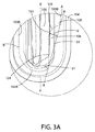
ここで、図3及び3Aを同時に参照すると、一実施形態に従う第1のパネル100のタブ106がより詳細に記載される。タブ106は、第1のパネル100の基部部分104の一部分であり、引き剥がし部分105に向かって側方に内側に突出する。例証するように、タブ106は、タブ106の基部122で、第1の内角120及び第2の内角121を備える。タブ106は、外角123を更に備える。例証される実施形態において、第1及び第2の内角120、121、ならびに外角123のいずれも、曲率半径を有する。第1及び第2の内角120、121のそれぞれの曲率半径は、外角123の曲率半径よりも小さい。他の実施形態において、第1及び第2の内角120、121ならびに/または外角123は、実質的に矩形であってもよい。
3 and 3A simultaneously, the
タブ106は、第1の内角120から第2の外角121へと延びる(予脆弱化線103の第1の部分103Aの一部分である)縁124を備える。縁124は、遠位部分125を備える。以下により詳細に論じるように、パッケージ2000の開封中、タブ106に適用される下向きの力Fは、予脆弱化線103の第1の部分103Aをタブ106の縁124に沿って剪断する。その後、タブ106は空洞500内に下向きに偏向する。該偏向中に、タブ106は、屈曲軸B−Bを中心に折曲/屈曲する。特定の実施形態において、屈曲軸B−Bは、第1の内角120と第2の内角121との間に延び、それらと交差する。屈曲軸B−Bは、図1〜5の例証される実施形態において、空洞150の長手方向軸A−Aに対して斜方に配向される。縁24の最遠位部分は、屈曲軸B−Bから距離dに位置する。
The
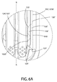
例証される実施形態において、タブ106は、予脆弱化線103によって形成される幾可学的形状の角に位置する。他の実施形態において、タブ106は、予脆弱化線103によって形成される幾可学的形状に沿った異なる位置に位置し得る。例えば、図6及び9に例証される実施形態において、タブ106は、予脆弱化線103の直線側の区分上に位置する。この実施形態において、屈曲軸B−B(図6Aを参照されたい)は、長手方向軸A−Aに対して実質的に平行に配向される。他の実施形態(図示せず)において、屈曲軸B−Bが長手方向軸A−Aに対して実質的に垂直に配向されるように、タブ106は予脆弱化線103の底部の直線部分に沿って位置し得る。特定のそのような実施形態において、タブ106は、位置とは無関係に、第2の部分103Bの剪断強度よりも小さい剪断強度を有する第1の予脆弱化パターンを有する、予脆弱化線103の第1の部分103Aによって画定され得る。
In the illustrated embodiment, the
ここで、図3〜5を同時に参照すると、互いに相対する、空洞500内の歯ブラシ3000の位置付け及びタブ106の位置は、パッケージ2000の開封を補助するように戦略的に選択される。歯ブラシの一部分3050が、第1のパネルの引き剥がし部分105の第1の部分130の下に置かれるように、歯ブラシ3000は空洞500内に位置付けられる。第1のパネルの引き剥がし部分105の第1の部分130は、第1のパネル100の基部部分104のタブ105に隣接する。タブ106は、空洞500の非占有部分501の上に位置する。空洞500の非占有部分501は、空洞500の床302から第1のパネル100の底表面102まで空である。図4で見ることができるように、第1のパネル100が位置する平面に対して実質的に垂直な方向で測定される場合、例証される実施形態において、口腔ケア用具のうちのどの部分も、タブ106の下には位置しない。
Referring now to FIGS. 3-5 simultaneously, the positioning of the
下向きの力Fがタブ106に適用されるとき、タブ106に隣接する引き剥がし部分105の第1の部分130は、歯ブラシ3000の部分3050と接触する。したがって、歯ブラシ3000の部分3050は、引き剥がし部分105がタブ106とともに下向きに屈曲し続けることを防止する基盤(または障壁)としての役割を果たす。特定の実施形態において、下向きの力が適用される前に、歯ブラシ3000の部分3050と引き剥がし部分105の第1の部分130との間に小間隙505が存在してもよい。他の実施形態において、下向きの力が適用される前に、歯ブラシ3000の部分3050は、引き剥がし部分105の第1の部分130と接触してもよい。
When a downward force F is applied to the
引き剥がし部分105の第1の部分130が接歯ブラシ3000の部分3050と接触すると、下向きの力Fの連続した適用は、予脆弱化線303の第1の部分303Aがタブ106の縁124に沿って剪断することをもたらし、これによりタブ106の縁124を引き剥がし部分105から解放する。したがって、タブ106は、予脆弱化線303の第1の部分303Aがそのままである閉鎖状態(図4)から、予脆弱化線303の第1の部分303Aが剪断され、タブ106が空洞500の部分の非占有部分501内に偏向される開封状態(図5)へと変更される。空洞500は、タブ106の下で非占有であるため、タブ106は、歯ブラシ3000の部分5030の上表面5031の下の深さまで空洞500の非占有部分501内に屈曲され得る。タブ106が閉鎖状態から開封状態へと変更されるにつれて、タブ106の縁124の遠位部分125は、経路Pに沿って移動する。一実施形態において、タブ106の縁124の遠位部分125は、少なくとも30度、及び他の実施形態において少なくとも45度の外周経路にわたって、経路Pに沿って移動する。特定の実施形態において、経路Pは、歯ブラシ3000のいずれの部分とも交差しない。他の実施形態において、タブ106が屈曲し、歯ブラシ3000の部分3050に乗り上げ得るのにタブ106が十分に軟性である限り、経路Pは歯ブラシの一部分と少しだけ交差してもよい。
When the
上の結果として、空洞500内への開口部510が形成され、ユーザはこれを通して、その後彼/彼女の指を滑入させ、引き剥がし部分105を把持することができる。ユーザが引き剥がし部分105を把持すると、彼/彼女は外側に引っ張り、これにより引き剥がし部分105を、予脆弱化線103の残りのそのままの部分に沿って基部部分104から切断させる。引き剥がし部分105が予脆弱化線103に沿って基部部分104から切断されると、引き剥がし部分105は、基部部分104に対して平面から引っ張り出される。結果として、パッケージ2000が開封され、歯ブラシ200がそこから取り除かれる。
As a result of the above, an
上の実施例において、柄3030の下部分は、引き剥がし部分105の第1の部分130に接触して、予脆弱化線303の第1の部分303Aを剪断して、タブ106の解放を補助する基盤(または障壁)として使用される歯ブラシ3000の部分3050であるものの、歯ブラシ3000及び/またはタブ106を適切に再位置付けすることによって、歯ブラシ3000の他の部分が基盤(または障壁)として利用され得る。例えば、特定の実施形態において、ヘッド3010または首3020が部分3050として使用され得る。
In the above example, the lower portion of the
予脆弱化線103によって画定される幾可学的形状のその不規則な外観の性質のため、タブ106は、ユーザに対する、タブ106の位置が下向きの力Fを適用するのに適切な場所であるという視覚的指標としての役割を果たし得る。これは、(より小さい剪断強度を有する)予脆弱化線303の第1の部分303Aがタブ106に隣接して位置し、したがってそれが最も容易に剪断する予脆弱化線303の部分であるという点において有益である。いくつかの実施形態において、タブ106は省略され、第1の部分303Aなどのように、より小さい剪断強度を有する予脆弱化線303の一部分に隣接して位置する視覚的指標によって置換されてもよい。視覚的指標は、予脆弱化線303の「容易な切断」部分であるその位置に、力が適用されるべきであることをユーザに合図する、矢印、図画、または英数字列であってもよい。そのような一実施形態において、歯ブラシ3000の部分3050は、上述するように、依然として最初の剪断を補助するための基盤(または基部)として使用され得る。
Due to the irregular appearance nature of the geometric shape defined by the
ここで、図6〜8を同時に参照すると、本発明の別の実施形態に従うパッケージ化された口腔ケア用具1000’が図示される。パッケージ化された口腔ケア用具1000’は、パッケージ2000’(及びその構成要素パネル100’、200’、300’、400’)が、1つではなく2つの歯ブラシ3000’を収容するように構成されることを除いて、図1〜5のパッケージ化された口腔ケア用具1000と同一である。更に、タブ106’は、角から予脆弱化線303’の直線側へと移転されている。したがって、冗長性を避けるために、パッケージ化された口腔ケア用具1000について上に説明される記述が適用可能であるという理解の下、パッケージ化された口腔ケア用具1000とは異なるパッケージ化された口腔ケア用具1000’の態様のみが後述される。したがって、’という接尾辞が付け加えられていることを除いて、同様の要素を指すために同様の参照番号が使用される。
6-8, a packaged oral care device 1000 'according to another embodiment of the present invention is illustrated. Packaged oral care device 1000 'is configured such that package 2000' (and its component panels 100 ', 200', 300 ', 400') contains two toothbrushes 3000 'instead of one. Otherwise, it is identical to the packaged
タブ106’は、予脆弱化線103’の直線区分から突出する。例証するように、タブ106’は、タブ106’の基部122’で、第1の内角120’及び第2の内角121’を備える。タブ106’は、第1の外角123’及び第2の外角129’を更に備える。例証される実施形態において、第1及び第2の内角120’、121’、ならびに第1及び第2の外角123’、129’のうちのいずれも、曲率半径を有する。第1及び第2の内角120’、121’のそれぞれの曲率半径は、第1及び第2の外角123’、129’の曲率半径よりも小さい。他の実施形態において、第1及び第2の内角120、121ならびに/または第1及び第2の外角123’、129’は、実質的に矩形であってもよい。
Tab 106 'protrudes from the straight section of pre-weakening line 103'. As illustrated, the tab 106 'comprises a first interior angle 120' and a second interior angle 121 'at the base 122' of the tab 106 '. The tab 106 'further includes a first outer angle 123' and a second outer angle 129 '. In the illustrated embodiment, each of the first and second interior angles 120 ', 121' and the first and second exterior angles 123 ', 129' have a radius of curvature. The curvature radii of the first and second
タブ106’は、第1の内角120’から第2の外角121’へと延びる(予脆弱化線の第1の部分103A’の一部分である)縁124’を備える。縁124’は、遠位部分125’を備える。パッケージ2000’の開封中、タブ106’に適用される下向きの力Fは、予脆弱化線103’の第1の部分103A’をタブ106’の縁124’に沿って剪断し、タブ106’は、空洞500’内に偏向する。該偏向中に、タブ106’は、屈曲軸B−Bを中心に折曲/屈曲する。特定の実施形態において、屈曲軸B−Bは、第1の内角120’と第2の内角121’との間に延び、それらと交差する。屈曲軸B−Bは、空洞150’の長手方向軸A−Aに対して実質的に平行に配向される。上述のように、タブ106’は、他の実施形態において、三角形、矩形、半卵形を非限定的に含む多種多様の形状を取り得る。
Tab 106 'includes an edge 124' that extends from a first interior angle 120 'to a second exterior angle 121' (which is part of the
ここで図9を参照すると、本発明の更なる一実施形態に従うパッケージ化された口腔ケア用具1000’’が図示される。パッケージ化された口腔ケア用具1000’’は、タブ106’’の長さが伸長されていることを除いて、図6〜7のパッケージ化された口腔ケア用具1000’と同一である。’’という接尾辞が付け加えられていることを除いて、同様の要素を指すために同様の参照番号が使用される。パッケージ化された口腔ケア用具1000’’についての更なる記述が必要であるとは考えられない。
Referring now to FIG. 9, a packaged
本明細書を通して使用される場合、範囲は、その範囲内にある各値及び全ての値を記載するための簡略表記法として使用される。その範囲内にある任意の値が、その範囲の終点として選択され得る。更に、本明細書に引用される全ての参考文献は、その全体が参照されたによって組み込まれる。本開示の定義及び引用される参考文献の定義における矛盾が生じた場合、本開示が制御する。 As used throughout this specification, a range is used as a shorthand notation for describing each and every value within that range. Any value within the range can be selected as the end point of the range. Furthermore, all references cited herein are incorporated by reference in their entirety. In the event of a conflict in a definition in the present disclosure and that of a cited reference, the present disclosure controls.
先の記述及び図面は、本発明の例示的な実施形態を提示する一方で、本発明の趣旨及び範囲から逸脱することなく、その中に、添付の請求項に定義されるような様々な追加、修正、及び置換がなされ得ることが理解されたい。特に、本発明が、その趣旨または本質的特徴から逸脱することなく、他の特定の形態、構造、配置、割合、大きさで、ならびに他の要素、材料、及び構成要素とともに実施され得ることは、当業者にとって明らかであろう。当業者は、本発明が、本発明の原理から逸脱することなく、特定の環境及び操作要求に特に適合された、構造、配置、割合、大きさ、材料、及び構成要素の多くの修正とともに使用され得ること、ならびに他の方法で本発明の実践において使用されることを理解するであろう。したがって、開示される本実施形態は、全ての点において制限的ではなく例示的であり、本発明の範囲は添付の請求項によって定義され、かつ先の記述または実施形態に限定されないものとして見なされるべきである。 While the foregoing description and drawings present exemplary embodiments of the invention, various additions may be made therein as defined in the appended claims without departing from the spirit and scope of the invention. It should be understood that modifications, substitutions, and substitutions can be made. In particular, the invention may be practiced in other specific forms, structures, arrangements, proportions, sizes, and with other elements, materials, and components without departing from its spirit or essential characteristics. Will be apparent to those skilled in the art. Those skilled in the art will recognize that the present invention may be used with many modifications of structure, arrangement, proportion, size, material, and components that are specifically adapted to specific environmental and operational requirements without departing from the principles of the present invention. It will be understood that it can be used as well as used in the practice of the present invention in other ways. Accordingly, the disclosed embodiments are illustrative in all respects rather than restrictive, and the scope of the present invention is defined by the appended claims and is not considered to be limited to the foregoing description or embodiments. Should.
Claims (28)
第1のパネル及び第2のパネル、前記第1のパネルと前記第2のパネルとの間に形成された空洞を備え、
前記第1のパネルが、引き剥がし部分及び基部部分を画定する、少なくとも1つの予脆弱化線を含み、前記基部部分が、前記第2のパネルに連結され、
前記基部部分が、前記引き剥がし部分内に突出するタブを備え、前記タブが、前記予脆弱化線の第1の部分によって画定され、
更に、前記空洞内に位置付けられた前記口腔ケア用具であって、その一部分が、前記タブに隣接する前記引き剥がし部分の第1の部分の下に置かれるように位置付けられ、前記タブが、前記空洞の非占有部分上に位置する、口腔ケア用具を備え、
前記タブが、前記タブに適用される下向きの力に応答して、(1)前記予脆弱化線の前記第1の部分がそのままである閉鎖状態、及び(2)前記予脆弱化線の前記第1の部分が剪断され、前記タブが前記口腔ケア用具の前記部分の上表面の下の深さまで前記非占有部分内に偏向される開封状態、から変更可能である、前記パッケージ化された口腔ケア用具。 A packaged oral care device,
A first panel and a second panel, comprising a cavity formed between the first panel and the second panel;
The first panel includes at least one pre-weakening line defining a tear-off portion and a base portion, the base portion coupled to the second panel;
The base portion comprises a tab projecting into the tear-away portion, the tab defined by a first portion of the pre-weakening line;
Further, the oral care device positioned within the cavity, wherein a portion thereof is positioned to be placed under a first portion of the tear-off portion adjacent to the tab, the tab being Comprising an oral care device located on an unoccupied portion of the cavity;
The tab is responsive to a downward force applied to the tab; (1) a closed state in which the first portion of the pre-weakening line remains intact; and (2) the pre-weakening line. The packaged oral cavity wherein the first portion is sheared and the tab is changeable from an open state wherein the tab is deflected into the unoccupied portion to a depth below the upper surface of the portion of the oral care device. Care tools.
第1のパネル及び第2のパネル、前記第1のパネルと前記第2のパネルとの間に形成された空洞を備え、
前記第1のパネルが、引き剥がし部分及び基部部分を画定する、少なくとも1つの予脆弱化線を含み、前記基部部分が、前記第2のパネルに連結され、
前記基部部分が、前記引き剥がし部分内に突出するタブを備え、前記タブが、前記予脆弱化線の第1の部分によって画定され、
更に、前記空洞内に位置付けられた前記口腔ケア用具であって、その一部分が、前記タブに隣接する前記引き剥がし部分の第1の部分の下に置かれるように位置付けられ、前記タブが、前記空洞の非占有部分上に位置する、口腔ケア用具を備える、前記パッケージ化された口腔ケア用具。 A packaged oral care device,
A first panel and a second panel, comprising a cavity formed between the first panel and the second panel;
The first panel includes at least one pre-weakening line defining a tear-off portion and a base portion, the base portion coupled to the second panel;
The base portion comprises a tab projecting into the tear-away portion, the tab defined by a first portion of the pre-weakening line;
Further, the oral care device positioned within the cavity, wherein a portion thereof is positioned to be placed under a first portion of the tear-off portion adjacent to the tab, the tab being The packaged oral care device comprising an oral care device located on an unoccupied portion of the cavity.
パッケージの空洞内に配設される製品を提供することであって、前記パッケージが、第1のパネルと、第2のパネルと、前記第1のパネルと前記第2のパネルとの間に形成される空洞とを備え、前記第1のパネルが、引き剥がし部分及び基部部分を画定する、少なくとも1つの予脆弱化線を含み、前記基部部分が、前記第2のパネルに連結され、前記基部部分が前記引き剥がし部分内に突出するタブを備え、前記タブが前記予脆弱化線の第1の部分によって画定され、前記製品の一部分が、前記タブに隣接する前記引き剥がし部分の第1の部分の下に置かれるように、前記製品が空洞内に位置付けられ、前記タブが、前記空洞の非占有部分上に位置する、提供することと、
下向きの力を前記タブ上に適用して、前記引き剥がし部分の前記第1の部分が前記製品の前記部分に接触し、前記予脆弱化線の前記第1の部分を剪断して、前記タブを解放させることであって、前記タブが前記製品の前記部分の上表面の下の深さまで前記非占有部分内に偏向し、これにより前記第1のパネル内に開口部を形成する、解放させることと、
前記開口部を介して前記引き剥がし部分を把持し、前記引き剥がし部分を前記基部部分から少なくとも部分的に分離させて、前記製品への到達を提供することと、を含む、前記方法。 A method of opening a packaged product, comprising:
Providing a product disposed in a cavity of a package, wherein the package is formed between a first panel, a second panel, and the first panel and the second panel. The first panel includes at least one pre-weakening line defining a tear-off portion and a base portion, the base portion being coupled to the second panel, the base portion A portion comprising a tab projecting into the peel portion, the tab being defined by a first portion of the pre-weakening line, wherein a portion of the product is a first portion of the peel portion adjacent to the tab. Providing the product is positioned in a cavity such that the tab is positioned on an unoccupied portion of the cavity, such that the product is positioned in a cavity.
A downward force is applied on the tab so that the first portion of the peeled portion contacts the portion of the product and shears the first portion of the pre-weakening line, the tab The tab is deflected into the unoccupied portion to a depth below the upper surface of the portion of the product, thereby forming an opening in the first panel. And
Gripping the tear-off portion through the opening and at least partially separating the tear-off portion from the base portion to provide access to the product.
Applications Claiming Priority (1)
| Application Number | Priority Date | Filing Date | Title |
|---|---|---|---|
| PCT/US2013/069601 WO2015072965A1 (en) | 2013-11-12 | 2013-11-12 | Packaged oral care implement & method of opening the same |
Publications (2)
| Publication Number | Publication Date |
|---|---|
| JP2016539865A true JP2016539865A (en) | 2016-12-22 |
| JP2016539865A5 JP2016539865A5 (en) | 2017-02-09 |
Family
ID=49641888
Family Applications (1)
| Application Number | Title | Priority Date | Filing Date |
|---|---|---|---|
| JP2016527345A Pending JP2016539865A (en) | 2013-11-12 | 2013-11-12 | Packaged oral care device and method for opening it |
Country Status (12)
| Country | Link |
|---|---|
| US (1) | US9751676B2 (en) |
| EP (1) | EP3057878A1 (en) |
| JP (1) | JP2016539865A (en) |
| KR (1) | KR20160085264A (en) |
| CN (1) | CN105764809B (en) |
| AU (1) | AU2013405186A1 (en) |
| CA (1) | CA2922555A1 (en) |
| MX (1) | MX2016005826A (en) |
| PH (1) | PH12016500727A1 (en) |
| RU (1) | RU2640457C2 (en) |
| TW (1) | TW201527187A (en) |
| WO (1) | WO2015072965A1 (en) |
Families Citing this family (2)
| Publication number | Priority date | Publication date | Assignee | Title |
|---|---|---|---|---|
| WO2016023221A1 (en) | 2014-08-15 | 2016-02-18 | Colgate-Palmolive Company | Packaged oral care implement |
| US10106304B2 (en) | 2015-06-23 | 2018-10-23 | Colgate-Palmolive Company | Oral care implement package |
Citations (10)
| Publication number | Priority date | Publication date | Assignee | Title |
|---|---|---|---|---|
| US4209095A (en) * | 1979-05-07 | 1980-06-24 | Champion International Corporation | Closure for blister card type container |
| JPS58133566U (en) * | 1982-03-03 | 1983-09-08 | クロバ−株式会社 | blister packaging containers |
| JPS62146764U (en) * | 1986-03-11 | 1987-09-16 | ||
| JPH0519159U (en) * | 1991-02-22 | 1993-03-09 | サンスター株式会社 | Blister pack |
| JP2002128140A (en) * | 2000-10-25 | 2002-05-09 | Sony Corp | Packaging member |
| JP2004203484A (en) * | 2002-05-29 | 2004-07-22 | Fujimori Kogyo Co Ltd | Packing body and method of attaching fluid |
| JP2005225563A (en) * | 2004-01-16 | 2005-08-25 | Oji Nepia Kk | Sanitary paper-filled carton |
| JP2009154948A (en) * | 2007-12-27 | 2009-07-16 | Panasonic Corp | Blister package |
| JP2010504888A (en) * | 2006-09-28 | 2010-02-18 | ダイアパック リミテッド | Break-open sealed single dose package |
| US20120145567A1 (en) * | 2010-12-13 | 2012-06-14 | Colgate-Palmolive Company | Easy opening display package for merchandise |
Family Cites Families (56)
| Publication number | Priority date | Publication date | Assignee | Title |
|---|---|---|---|---|
| US2985296A (en) * | 1957-10-18 | 1961-05-23 | Kahn David Inc | Display device |
| US3004661A (en) * | 1959-12-01 | 1961-10-17 | Star Brush Mfg Co Inc | Display and storage package for brushes |
| GB951214A (en) * | 1961-05-15 | 1964-03-04 | Topps Of England Ltd | Improvements in or relating to packages |
| US3689458A (en) | 1970-03-23 | 1972-09-05 | Hellstrom Harold R | Quick-opening fulcrum package |
| US3780856A (en) * | 1971-07-26 | 1973-12-25 | Medi Dose Inc | Medicinal dispensing device |
| US3942640A (en) | 1972-07-07 | 1976-03-09 | Hellstrom Harold R | Tear-away blister package |
| CH619409A5 (en) | 1977-10-04 | 1980-09-30 | Eduard Zdarsky | Cell package with dental root canal instruments |
| US4191293A (en) | 1978-08-09 | 1980-03-04 | Newman Morris M | Blister package |
| US4200193A (en) * | 1979-03-05 | 1980-04-29 | Champion International Corporation | Easy opening, recloseable blister card container |
| CH678713A5 (en) | 1989-05-18 | 1991-10-31 | Renata Ag | |
| US5215381A (en) | 1990-04-17 | 1993-06-01 | Wade Steven E | Opening device for flexible packaging |
| US5551564A (en) | 1994-02-02 | 1996-09-03 | Prater; James L. | Roll package convertible to a dispenser |
| BR9504036A (en) | 1994-09-15 | 1996-09-24 | Reynolds Metals Co | Can end containing fixed handle with rim over the breaking section allowing broad contact with the handle to increase the length of the spline line break |
| AUPQ933700A0 (en) | 2000-08-10 | 2000-08-31 | Western Research & Development Pty Ltd | Tamper proof product dispenser |
| US6915901B2 (en) * | 2000-12-11 | 2005-07-12 | Marc Feinberg | Packaging assembly for surgical use |
| US6571953B2 (en) | 2001-05-03 | 2003-06-03 | One Source Industries, Llc | Printed-thermoplastic tamper-resistant package |
| ATE411955T1 (en) | 2002-09-05 | 2008-11-15 | Colgate Palmolive Co | TOOTHBRUSH PACKAGING |
| US6830385B2 (en) | 2002-09-30 | 2004-12-14 | Hitachi Cable, Ltd. | Package having lock mechanism |
| US20040206253A1 (en) | 2003-02-18 | 2004-10-21 | Lundberg John D. | Rotary engraving apparatus |
| US7188728B2 (en) | 2003-03-20 | 2007-03-13 | Wade Everette Williams-Hartman | Child-resistant and senior-friendly blister card package |
| US20050167311A1 (en) | 2003-10-14 | 2005-08-04 | Brad Tonsfeldt | Dispenser package arrangement and methods |
| DE602005007180D1 (en) | 2004-01-07 | 2008-07-10 | Meadwestvaco Corp | BLISTER AND PACKAGING SYSTEM |
| US20050218027A1 (en) * | 2004-04-02 | 2005-10-06 | Lammers Anthony J | Package with integral plug |
| US7243798B2 (en) | 2004-08-04 | 2007-07-17 | Fisher Clinical Services | System and a method for a V-indent blister opening cavity |
| WO2006052490A2 (en) | 2004-11-05 | 2006-05-18 | Morrison David J | Package/container for batteries |
| US20060249422A1 (en) | 2005-05-05 | 2006-11-09 | Bates Ronald R Jr | Child-resistant blister package with tear tab |
| US7395928B2 (en) | 2005-07-14 | 2008-07-08 | Abbott Laboratories | Child-resistant blister package |
| ATE482150T1 (en) | 2005-08-01 | 2010-10-15 | Stora Enso Ab | METHOD FOR HOLDING PACKAGINGS TOGETHER AND HOLDING COMPONENTS THEREON |
| AU2006276352A1 (en) | 2005-08-01 | 2007-02-08 | Stora Enso Ab | A package |
| US20070045154A1 (en) | 2005-08-26 | 2007-03-01 | Gelardi John A | Package that provides immediate access |
| US20070068844A1 (en) | 2005-09-28 | 2007-03-29 | Weston Michael H | Child resistant package |
| US20070102317A1 (en) | 2005-11-08 | 2007-05-10 | Colgate-Palmolive Company | Easy open thermoformed package |
| US20070256307A1 (en) | 2006-05-08 | 2007-11-08 | Andre Mann | Method and device for dispensing articles from blister packs |
| US8191713B2 (en) | 2006-07-11 | 2012-06-05 | Mattel, Inc. | Interactive display packaging for a toy figure |
| US20080038046A1 (en) | 2006-08-11 | 2008-02-14 | Reza Jalili | Dental Cleaning Substance Medium, Packaging, and Device |
| US8042689B2 (en) | 2006-11-22 | 2011-10-25 | Becton, Dickinson And Company | Extravascular system packaging systems |
| US20080173564A1 (en) | 2007-01-22 | 2008-07-24 | Cadbury Adams Usa Llc. | Package having a dispensing opening and fold over flap |
| US7621405B2 (en) | 2007-06-20 | 2009-11-24 | Eveready Battery Co., Inc. | Lithium battery package |
| US20090090643A1 (en) | 2007-10-05 | 2009-04-09 | Trisa Holding Ag | Blister package for display of a toothbrush |
| US7926660B2 (en) | 2008-10-27 | 2011-04-19 | Meadwestvaco Corporation | Child resistant blister package housing with tooled access |
| WO2009061933A1 (en) | 2007-11-06 | 2009-05-14 | Monosol, Llc | Water-soluble containers within a secondary blister package |
| US8011512B2 (en) | 2008-01-18 | 2011-09-06 | International Paper Co. | Child-resistant package with latch and retaining feature |
| US20110042262A1 (en) | 2008-04-30 | 2011-02-24 | Bilcare Limited | Restricted Product Access Package System |
| US20100018974A1 (en) | 2008-07-24 | 2010-01-28 | Deborah Lyzenga | Package integrity indicating closure |
| US20100059401A1 (en) | 2008-09-10 | 2010-03-11 | All About Packaging Inc | Blister package having a securement mechanism and a method of forming and filing said blister package |
| RU2494942C2 (en) * | 2009-03-16 | 2013-10-10 | Колгейт-Палмолив Компани | Display package |
| US8066122B2 (en) | 2009-04-01 | 2011-11-29 | Berry Plastics Corporation | Child-resistant package with pivotable blister card |
| CN201411136Y (en) * | 2009-06-03 | 2010-02-24 | 韩信 | Easy-opening toothbrush packaging box |
| US7931148B2 (en) | 2009-06-10 | 2011-04-26 | Display Pack, Inc. | Double hinge display package and method of use |
| TWI401189B (en) | 2009-09-18 | 2013-07-11 | Colgate Palmolive Co | Display package for a plurality of products |
| US20110100845A1 (en) | 2009-10-31 | 2011-05-05 | James Arthur Meech | Packaging for Concealing an Insert |
| US7922437B1 (en) | 2009-11-23 | 2011-04-12 | Meadwestvaco Corporation | Display system, dispensing device and package for use therein |
| JP5466069B2 (en) * | 2010-04-07 | 2014-04-09 | ユニ・チャーム株式会社 | Packaging case |
| CN102985028A (en) * | 2010-06-30 | 2013-03-20 | 博朗有限公司 | Oral care package |
| CA2844481C (en) | 2011-08-15 | 2016-07-12 | Colgate-Palmolive Company | Packaged oral care implement & package |
| US9980798B2 (en) * | 2011-12-16 | 2018-05-29 | Colgate-Palmolive Company | Packaged oral care implement |
-
2013
- 2013-11-12 WO PCT/US2013/069601 patent/WO2015072965A1/en active Application Filing
- 2013-11-12 EP EP13795667.8A patent/EP3057878A1/en not_active Withdrawn
- 2013-11-12 MX MX2016005826A patent/MX2016005826A/en unknown
- 2013-11-12 US US15/035,989 patent/US9751676B2/en active Active
- 2013-11-12 CA CA2922555A patent/CA2922555A1/en not_active Abandoned
- 2013-11-12 AU AU2013405186A patent/AU2013405186A1/en not_active Abandoned
- 2013-11-12 KR KR1020167012316A patent/KR20160085264A/en not_active Application Discontinuation
- 2013-11-12 CN CN201380080845.XA patent/CN105764809B/en active Active
- 2013-11-12 RU RU2016118029A patent/RU2640457C2/en active
- 2013-11-12 JP JP2016527345A patent/JP2016539865A/en active Pending
-
2014
- 2014-10-27 TW TW103136946A patent/TW201527187A/en unknown
-
2016
- 2016-04-19 PH PH12016500727A patent/PH12016500727A1/en unknown
Patent Citations (10)
| Publication number | Priority date | Publication date | Assignee | Title |
|---|---|---|---|---|
| US4209095A (en) * | 1979-05-07 | 1980-06-24 | Champion International Corporation | Closure for blister card type container |
| JPS58133566U (en) * | 1982-03-03 | 1983-09-08 | クロバ−株式会社 | blister packaging containers |
| JPS62146764U (en) * | 1986-03-11 | 1987-09-16 | ||
| JPH0519159U (en) * | 1991-02-22 | 1993-03-09 | サンスター株式会社 | Blister pack |
| JP2002128140A (en) * | 2000-10-25 | 2002-05-09 | Sony Corp | Packaging member |
| JP2004203484A (en) * | 2002-05-29 | 2004-07-22 | Fujimori Kogyo Co Ltd | Packing body and method of attaching fluid |
| JP2005225563A (en) * | 2004-01-16 | 2005-08-25 | Oji Nepia Kk | Sanitary paper-filled carton |
| JP2010504888A (en) * | 2006-09-28 | 2010-02-18 | ダイアパック リミテッド | Break-open sealed single dose package |
| JP2009154948A (en) * | 2007-12-27 | 2009-07-16 | Panasonic Corp | Blister package |
| US20120145567A1 (en) * | 2010-12-13 | 2012-06-14 | Colgate-Palmolive Company | Easy opening display package for merchandise |
Also Published As
| Publication number | Publication date |
|---|---|
| KR20160085264A (en) | 2016-07-15 |
| PH12016500727A1 (en) | 2016-05-30 |
| US20160297593A1 (en) | 2016-10-13 |
| EP3057878A1 (en) | 2016-08-24 |
| RU2016118029A (en) | 2017-12-19 |
| CA2922555A1 (en) | 2015-05-21 |
| CN105764809B (en) | 2018-09-04 |
| TW201527187A (en) | 2015-07-16 |
| MX2016005826A (en) | 2016-08-11 |
| AU2013405186A1 (en) | 2016-05-05 |
| CN105764809A (en) | 2016-07-13 |
| RU2640457C2 (en) | 2018-01-09 |
| US9751676B2 (en) | 2017-09-05 |
| WO2015072965A1 (en) | 2015-05-21 |
Similar Documents
| Publication | Publication Date | Title |
|---|---|---|
| US9505540B2 (en) | Packaged oral care implement and package | |
| EP2713985B1 (en) | Oral care kit for displaying a portion of a toothbrush | |
| JP2016539865A (en) | Packaged oral care device and method for opening it | |
| EP3057879B1 (en) | Oral care implement package and method of opening the same | |
| US10112760B2 (en) | Packaged oral care implement and package | |
| AU2013405188A1 (en) | Packaged oral care implement and method of opening the same | |
| CN112512934B (en) | Packaged oral care implement and package kit therefor |
Legal Events
| Date | Code | Title | Description |
|---|---|---|---|
| A521 | Request for written amendment filed |
Free format text: JAPANESE INTERMEDIATE CODE: A523 Effective date: 20161109 |
|
| A621 | Written request for application examination |
Free format text: JAPANESE INTERMEDIATE CODE: A621 Effective date: 20161109 |
|
| A521 | Request for written amendment filed |
Free format text: JAPANESE INTERMEDIATE CODE: A523 Effective date: 20161115 |
|
| A977 | Report on retrieval |
Free format text: JAPANESE INTERMEDIATE CODE: A971007 Effective date: 20170623 |
|
| A131 | Notification of reasons for refusal |
Free format text: JAPANESE INTERMEDIATE CODE: A131 Effective date: 20170704 |
|
| A02 | Decision of refusal |
Free format text: JAPANESE INTERMEDIATE CODE: A02 Effective date: 20180320 |