JP2016535826A - Diffuser for mixing vortices produced by struts - Google Patents
Diffuser for mixing vortices produced by struts Download PDFInfo
- Publication number
- JP2016535826A JP2016535826A JP2016516585A JP2016516585A JP2016535826A JP 2016535826 A JP2016535826 A JP 2016535826A JP 2016516585 A JP2016516585 A JP 2016516585A JP 2016516585 A JP2016516585 A JP 2016516585A JP 2016535826 A JP2016535826 A JP 2016535826A
- Authority
- JP
- Japan
- Prior art keywords
- span
- flap
- gas turbine
- span direction
- turbine engine
- Prior art date
- Legal status (The legal status is an assumption and is not a legal conclusion. Google has not performed a legal analysis and makes no representation as to the accuracy of the status listed.)
- Ceased
Links
Images


Classifications
-
- F—MECHANICAL ENGINEERING; LIGHTING; HEATING; WEAPONS; BLASTING
- F01—MACHINES OR ENGINES IN GENERAL; ENGINE PLANTS IN GENERAL; STEAM ENGINES
- F01D—NON-POSITIVE DISPLACEMENT MACHINES OR ENGINES, e.g. STEAM TURBINES
- F01D25/00—Component parts, details, or accessories, not provided for in, or of interest apart from, other groups
- F01D25/30—Exhaust heads, chambers, or the like
-
- F—MECHANICAL ENGINEERING; LIGHTING; HEATING; WEAPONS; BLASTING
- F01—MACHINES OR ENGINES IN GENERAL; ENGINE PLANTS IN GENERAL; STEAM ENGINES
- F01D—NON-POSITIVE DISPLACEMENT MACHINES OR ENGINES, e.g. STEAM TURBINES
- F01D17/00—Regulating or controlling by varying flow
- F01D17/10—Final actuators
- F01D17/12—Final actuators arranged in stator parts
- F01D17/14—Final actuators arranged in stator parts varying effective cross-sectional area of nozzles or guide conduits
- F01D17/141—Final actuators arranged in stator parts varying effective cross-sectional area of nozzles or guide conduits by means of shiftable members or valves obturating part of the flow path
- F01D17/143—Final actuators arranged in stator parts varying effective cross-sectional area of nozzles or guide conduits by means of shiftable members or valves obturating part of the flow path the shiftable member being a wall, or part thereof of a radial diffuser
-
- F—MECHANICAL ENGINEERING; LIGHTING; HEATING; WEAPONS; BLASTING
- F01—MACHINES OR ENGINES IN GENERAL; ENGINE PLANTS IN GENERAL; STEAM ENGINES
- F01D—NON-POSITIVE DISPLACEMENT MACHINES OR ENGINES, e.g. STEAM TURBINES
- F01D17/00—Regulating or controlling by varying flow
- F01D17/10—Final actuators
- F01D17/12—Final actuators arranged in stator parts
- F01D17/14—Final actuators arranged in stator parts varying effective cross-sectional area of nozzles or guide conduits
- F01D17/16—Final actuators arranged in stator parts varying effective cross-sectional area of nozzles or guide conduits by means of nozzle vanes
-
- F—MECHANICAL ENGINEERING; LIGHTING; HEATING; WEAPONS; BLASTING
- F05—INDEXING SCHEMES RELATING TO ENGINES OR PUMPS IN VARIOUS SUBCLASSES OF CLASSES F01-F04
- F05D—INDEXING SCHEME FOR ASPECTS RELATING TO NON-POSITIVE-DISPLACEMENT MACHINES OR ENGINES, GAS-TURBINES OR JET-PROPULSION PLANTS
- F05D2220/00—Application
- F05D2220/30—Application in turbines
- F05D2220/32—Application in turbines in gas turbines
-
- F—MECHANICAL ENGINEERING; LIGHTING; HEATING; WEAPONS; BLASTING
- F05—INDEXING SCHEMES RELATING TO ENGINES OR PUMPS IN VARIOUS SUBCLASSES OF CLASSES F01-F04
- F05D—INDEXING SCHEME FOR ASPECTS RELATING TO NON-POSITIVE-DISPLACEMENT MACHINES OR ENGINES, GAS-TURBINES OR JET-PROPULSION PLANTS
- F05D2240/00—Components
- F05D2240/10—Stators
- F05D2240/12—Fluid guiding means, e.g. vanes
- F05D2240/122—Fluid guiding means, e.g. vanes related to the trailing edge of a stator vane
-
- F—MECHANICAL ENGINEERING; LIGHTING; HEATING; WEAPONS; BLASTING
- F05—INDEXING SCHEMES RELATING TO ENGINES OR PUMPS IN VARIOUS SUBCLASSES OF CLASSES F01-F04
- F05D—INDEXING SCHEME FOR ASPECTS RELATING TO NON-POSITIVE-DISPLACEMENT MACHINES OR ENGINES, GAS-TURBINES OR JET-PROPULSION PLANTS
- F05D2240/00—Components
- F05D2240/10—Stators
- F05D2240/12—Fluid guiding means, e.g. vanes
- F05D2240/127—Vortex generators, turbulators, or the like, for mixing
-
- F—MECHANICAL ENGINEERING; LIGHTING; HEATING; WEAPONS; BLASTING
- F05—INDEXING SCHEMES RELATING TO ENGINES OR PUMPS IN VARIOUS SUBCLASSES OF CLASSES F01-F04
- F05D—INDEXING SCHEME FOR ASPECTS RELATING TO NON-POSITIVE-DISPLACEMENT MACHINES OR ENGINES, GAS-TURBINES OR JET-PROPULSION PLANTS
- F05D2250/00—Geometry
- F05D2250/70—Shape
Landscapes
- Engineering & Computer Science (AREA)
- Mechanical Engineering (AREA)
- General Engineering & Computer Science (AREA)
- Turbine Rotor Nozzle Sealing (AREA)
- Structures Of Non-Positive Displacement Pumps (AREA)
Abstract
ガスタービンエンジンは、環状ガス通路を形成する内側および外側シュラウド、ならびに内側シュラウドを外側シュラウドに接続する複数のストラットを有する。翼形シールドはストラットを包囲しており、シールドのそれぞれは、シールドの前縁から下流端部に向かって下流軸方向に延びる弦軸線を規定する上流前縁を有する本体を含む。後縁フラップは、各シールドの下流端部に配置されており、後縁フラップは第1および第2のスパン方向部分を有する。第1のスパン方向部分は、本体の弦軸線に対して所定の角度に流れを方向付けるように向けられており、第2のスパン方向部分は、第1のスパン方向部分の角度とは異なる角度の方向に流れを方向付けるように向けられている。The gas turbine engine has inner and outer shrouds that form an annular gas passage, and a plurality of struts that connect the inner shroud to the outer shroud. The airfoil shields surround the struts, each shield including a body having an upstream leading edge defining a chord axis extending in a downstream axial direction from the leading edge of the shield toward the downstream end. A trailing edge flap is disposed at the downstream end of each shield, and the trailing edge flap has first and second spanwise portions. The first span direction portion is oriented to direct the flow at a predetermined angle relative to the chord axis of the body, and the second span direction portion is an angle different from the angle of the first span direction portion. Is directed to direct the flow in the direction of.
Description
本発明は、一般にタービンエンジンに関し、特にタービンエンジン用の排気ディフューザに関する。 The present invention relates generally to turbine engines, and more particularly to an exhaust diffuser for a turbine engine.
図1を参照すると、タービンエンジン10は、一般に、圧縮機セクション12と、燃焼器セクション14と、タービンセクション16と、排気セクション18とを有する。作動時には、圧縮機セクション12は周囲空気を引き込み、空気を圧縮することができる。圧縮機セクション12からの圧縮空気は、燃焼器セクション14内の1つ又は複数の燃焼器20に進入することができる。圧縮空気を燃料と混合することができ、空気・燃料混合物を燃焼器20において燃焼させて、高温作動ガスを形成する。高温ガスをタービンセクション16へ送ることができ、そこで、高温ガスは、固定翼と回転翼の交互の列を通って膨張させられ、ロータ26を駆動することができる動力を発生させるために利用される。タービンセクション16から出た膨張したガスは、排気セクション18を通じてエンジン10から排出することができる。
With reference to FIG. 1, the turbine engine 10 generally includes a compressor section 12, a combustor section 14, a turbine section 16, and an
排気セクション18はディフューザ28として構成することができる。ディフューザ28は、外側シェル30と、中央ボディまたはハブ32と、支持ストラット36によって支持されたテールコーン34との間に形成された、拡開するダクトであってもよい。排気ディフューザ28は、排気流の速度を低下させ、これにより、タービンの最終段を横切って膨張する排ガスの差圧を増大させるように機能することができる。幾つかの従来のタービン排気セクションでは、流体流れ方向で排気ダクトの断面積を次第に増大させ、これにより排気ダクト内を流れる流体を膨張させることによって、排気の拡散が達成されており、通常は、設計作動条件における作動を最適化するように設計されている。これに加えて、ガスタービンエンジンは、一般に、設計点において望ましいディフューザ入口条件を提供するように設計されており、この設計点では、タービンセクション16から通過する排気流は、通常、流速およびスワールの、半径方向でバランスの取れた分配を有するように設計されている。
The
ガスタービンエンジンの作動の様々な変化は、ディフューザ入口において最適でない流れ条件を生じることがあり、特に、ディフューザに進入する、半径方向に歪められた流れを生じる可能性がある。例えば、非設計作動点、例えば、部分負荷運転または非設計周囲空気入口温度における作動の結果、ディフューザに進入する、半径方向で不均一な速度分布を生じることがある。また、エンジンの出力を増大するためなどの既存のエンジンの再設計は、ディフューザ内への流れを制御する構造が、エンジンを通る流れ条件に影響する変化のために再構成されていないと、ディフューザ入口において最適でない流れ条件を生じることがある。 Various changes in gas turbine engine operation can result in sub-optimal flow conditions at the diffuser inlet, and in particular can result in a radially distorted flow entering the diffuser. For example, operation at non-design operating points, such as part load operation or non-design ambient air inlet temperature, may result in a radially non-uniform velocity distribution entering the diffuser. Also, existing engine redesigns, such as to increase engine power, require that the structure controlling the flow into the diffuser is not reconfigured due to changes that affect the flow conditions through the engine. Non-optimal flow conditions may occur at the inlet.
本発明の1つの態様によれば、タービン排気セクションを有するガスタービンエンジンが提供される。ガスタービンエンジンは、同心状に間隔を置いて配置された一対のリングと、リングの間に半径方向に延び、リングを接続および支持した複数のストラット構造とを有する。ストラット構造は、回転ブレードの最終列の下流に支持されており、エンジンを通る軸方向ガス流の方向に延在した弦寸法を有する本体部分を有しており、本体部分の上流端部からストラット構造の下流端部に向かって下流方向へ延びる弦軸線を規定している。後縁フラップは、各本体部分の下流端部に配置されており、後縁フラップは第1および第2のスパン方向部分を有する。第1のスパン方向部分は、本体部分の弦軸線に対して所定の角度に流れを方向付けるように向けられており、第2のスパン方向部分は、第1のスパン方向部分の角度とは異なる角度の方向に流れを方向付けるように向けられている。 According to one aspect of the invention, a gas turbine engine having a turbine exhaust section is provided. The gas turbine engine has a pair of concentrically spaced rings and a plurality of strut structures that extend radially between the rings and connect and support the rings. The strut structure is supported downstream of the last row of rotating blades and has a body portion having a chord dimension extending in the direction of axial gas flow through the engine, struts from the upstream end of the body portion. A chord axis is defined that extends in a downstream direction toward the downstream end of the structure. A trailing edge flap is disposed at the downstream end of each body portion, and the trailing edge flap has first and second spanning portions. The first span direction portion is oriented to direct the flow at a predetermined angle relative to the chord axis of the body portion, and the second span direction portion is different from the angle of the first span direction portion. Directed to direct the flow in the direction of the angle.
第1のスパン方向部分は、弦軸線の第1の側への方向でフラップ角を規定してよく、第2のスパン方向部分は、弦軸線の、第1の側とは反対の第2の側への方向でフラップ角を規定してよい。 The first span direction portion may define a flap angle in a direction toward the first side of the chord axis, and the second span direction portion is a second end of the chord axis opposite the first side. The flap angle may be defined in the direction to the side.
第1のスパン方向部分のフラップ角の方向は、周方向で隣接する第1のスパン方向部分に関して交互になっていてもよく、第2のスパン方向部分のフラップ角の方向は、周方向で隣接する第2のスパン方向部分に関して交互になっていてもよい。 The direction of the flap angle of the first span direction portion may be alternating with respect to the first span direction portion adjacent in the circumferential direction, and the direction of the flap angle of the second span direction portion is adjacent in the circumferential direction The second span direction portion may be alternated.
各第1のスパン方向部分のフラップ角の方向は、全て同じ方向に向けられてもよく、各第2のスパン方向部分のフラップ角の方向は、全て同じ方向に向けられてもよい。 The direction of the flap angle of each first span direction portion may be all directed in the same direction, and the direction of the flap angle of each second span direction portion may be all directed in the same direction.
第1のスパン方向部分は、スパン方向中間位置から、ストラット構造に沿ってリングのうちの内側のリングに向かって延びていてもよく、第2のスパン方向部分は、中間位置からリングのうちの外側のリングに向かって延びていてもよい。 The first span direction portion may extend from the intermediate span direction position along the strut structure toward the inner ring of the ring, and the second span direction portion may extend from the intermediate position of the ring. It may extend towards the outer ring.
スパン方向中間位置は、本体のスパン中央に位置してもよい。 The intermediate position in the span direction may be located at the center of the span of the main body.
ストラット構造は、翼形シールドによって包囲されたストラットを有してもよく、ストラット構造は、エンジン用の排気ディフューザの上流端部に配置されていてもよい。 The strut structure may have a strut surrounded by an airfoil shield, and the strut structure may be located at the upstream end of an exhaust diffuser for an engine.
第1および第2のスパン方向部分は、本体に対して可動であってもよく、第1のスパン方向部分は、第2のスパン方向部分から独立して可動であってもよい。 The first and second span direction portions may be movable with respect to the body, and the first span direction portion may be movable independently of the second span direction portion.
ストラット構造は、平坦なディバイダを含んでもよい。この平坦なディバイダは、第1および第2のスパン方向部分の間のスパン方向移行部と交差する軸方向および周方向に延びる平面に位置しており、第1および第2のスパン方向部分の間の半径方向流れを制限する。 The strut structure may include a flat divider. The flat divider is located in an axially and circumferentially extending plane that intersects the spanwise transition between the first and second spanning portions and between the first and second spanning portions. Restrict the radial flow of
本発明の別の態様によれば、排気ディフューザを有するガスタービンエンジンが提供される。ガスタービンエンジンは、環状ガス通路を形成する内側シュラウドおよび外側シュラウド、ならびに内側シュラウドを外側シュラウドに接続する複数のストラットを有する。ストラットは、回転ブレードの最終列の下流においてガス通路内に配置されている。翼形シールドはストラットを包囲しており、各シールドは、シールドの前縁から下流端部に向かって下流軸方向に延びる弦軸線を規定する、上流前縁を有する本体を含む。後縁フラップは、各シールドの下流端部に配置されており、後縁フラップは第1および第2のスパン方向部分を有する。第1のスパン方向部分は、本体の弦軸線に対して所定の角度に流れを方向付けるように向けられており、第2のスパン方向部分は、第1のスパン方向部分の角度とは異なる角度の方向に流れを方向付けるように向けられている。 According to another aspect of the invention, a gas turbine engine having an exhaust diffuser is provided. The gas turbine engine has an inner shroud and an outer shroud that form an annular gas passage, and a plurality of struts that connect the inner shroud to the outer shroud. The strut is disposed in the gas passage downstream of the last row of rotating blades. Airfoil shields surround the struts, each shield including a body having an upstream leading edge that defines a chord axis extending in a downstream axial direction from the leading edge of the shield toward the downstream end. A trailing edge flap is disposed at the downstream end of each shield, and the trailing edge flap has first and second spanwise portions. The first span direction portion is oriented to direct the flow at a predetermined angle relative to the chord axis of the body, and the second span direction portion is an angle different from the angle of the first span direction portion. Is directed to direct the flow in the direction of.
各シールドのために、第1のスパン方向部分は、弦軸線の第1の側への方向でフラップ角を規定してよく、第2のスパン方向部分は、弦軸線の、第1の側とは反対の第2の側への方向でフラップ角を規定してよい。 For each shield, the first span direction portion may define a flap angle in a direction toward the first side of the chord axis, and the second span direction portion is defined on the first side of the chord axis. May define the flap angle in the direction to the opposite second side.
第1のスパン方向部分のフラップ角の方向は、周方向で隣接する第1のスパン方向部分に関して交互になっていてよく、第2のスパン方向部分のフラップ角の方向は、周方向で隣接する第2のスパン方向部分に関して交互になっていてよい。 The direction of the flap angle of the first span direction portion may be alternating with respect to the first span direction portion adjacent in the circumferential direction, and the direction of the flap angle of the second span direction portion is adjacent in the circumferential direction. Alternately with respect to the second span direction portion.
各第1のスパン方向部分のフラップ角の方向は、全て同じ方向に向けられていてもよく、各第2のスパン方向部分のフラップ角の方向は、全て同じ方向に向けられていてもよい。 The directions of the flap angles of the respective first span direction portions may all be directed in the same direction, and the directions of the flap angles of the respective second span direction portions may all be directed in the same direction.
第1のスパン方向部分は、スパン方向中間位置から、シールドに沿って内側シュラウドに向かって延びていてもよく、第2のスパン方向部分は、中間位置から外側シュラウドに向かって延びていてもよい。 The first span direction portion may extend from the intermediate span position toward the inner shroud along the shield, and the second span direction portion may extend from the intermediate position toward the outer shroud. .
スパン方向中間位置は、シールドのスパン中央に位置してもよい。 The intermediate position in the span direction may be located at the center of the span of the shield.
第1および第2のスパン方向部分は、弦軸線に対して可動であってもよい。 The first and second spanwise portions may be movable relative to the chord axis.
第2のスパン方向部分から独立した移動において第1のスパン方向部分を作動させるために、第1および第2のスパン方向部分にアクチュエータが接続されていてもよい。 Actuators may be connected to the first and second spanning portions for actuating the first spanning portion in movement independent of the second spanning portion.
ストラット構造は、平坦なディバイダを含んでもよく、この平坦なディバイダは、第1および第2のスパン方向部分の間のスパン方向移行部と交差する軸方向および周方向に延びる平面に位置しており、半径方向流れを制限しかつ第1および第2のスパン方向部分の間の機械的剛性を高める。 The strut structure may include a flat divider, the flat divider being located in an axially and circumferentially extending plane that intersects the span transition between the first and second spanning portions. Restrict radial flow and increase the mechanical stiffness between the first and second spanned portions.
本明細書は、本発明を特に指摘し、かつ本発明を明瞭に請求する請求項によって完結するが、同じ参照符号が同じ要素を表している添付の図面に関連した以下の説明から、本発明はよりよく理解されると考えられる。 DETAILED DESCRIPTION OF THE INVENTION The specification concludes with the claims particularly pointing out and distinctly claiming the invention, from the following description in conjunction with the accompanying drawings, wherein like reference numerals represent like elements, and in which: Will be better understood.
好適な実施の形態の以下の詳細な説明において、その一部を形成する添付の図面が参照され、図面には、例として、限定としてではなく、発明を実施可能な特定の好適な実施の形態が示されている。本発明の思想および範囲から逸脱することなく、その他の実施の形態が使用されてもよく、変更がなされてもよいことが理解されるべきである。 In the following detailed description of the preferred embodiments, reference is made to the accompanying drawings that form a part hereof, and in which is shown by way of illustration and not limitation, specific preferred embodiments in which the invention may be practiced. It is shown. It is to be understood that other embodiments may be used and changes may be made without departing from the spirit and scope of the present invention.
本発明の1つの態様によれば、ディフューザの半径方向内側および外側の領域の間の流速分布の均一性の改良を含む、ディフューザを通過する流れの半径方向の混合を増加させることによって、改良されたディフューザ性能を提供するディフューザ設計が説明される。本明細書において説明されるディフューザの典型的な適用において、ハブにおける強い速度分布の一般的な発生は、本発明によって、内側境界(ハブ)の近くのより高速の流れを外方へ移動させ、外側境界の近くのより低速の流れを内方へ移動させるスワール流を形成し、その結果、流れの混合を生ぜしめることによって、解決することができる。 In accordance with one aspect of the present invention, improved by increasing the radial mixing of the flow through the diffuser, including improving the uniformity of the flow velocity distribution between the radially inner and outer regions of the diffuser. Diffuser designs that provide diffuser performance are described. In the typical application of the diffuser described herein, the general occurrence of a strong velocity distribution at the hub causes the faster flow near the inner boundary (hub) to move outward, according to the present invention, This can be solved by creating a swirl flow that moves inward the slower flow near the outer boundary, resulting in flow mixing.
図2は、本発明の態様に従って構成されたガスタービンエンジンの排気ディフューザ40の一部を含む排気セクションを示している。排気ディフューザ40は、図1に示されたエンジン10のタービンセクション16に対応してもよい、エンジンのタービンセクションの回転ブレードの最終列の下流にある。排気ディフューザ40は、タービンセクションから出てくる排気流または排ガス44を受け取ることができる入口42を有する。排気ディフューザ40は、内側リングを含んでもよい内側境界46と、外側リングを含んでもよい外側境界48とを有する。外側境界48は、内側境界46から半径方向に間隔を置いて配置されており、内側および外側境界46,48の間には流路50が形成されている。流路50は、略環状であってもよいし、またはあらゆるその他の適切な構成を有してもよい。 FIG. 2 illustrates an exhaust section that includes a portion of an exhaust diffuser 40 of a gas turbine engine constructed in accordance with an aspect of the present invention. The exhaust diffuser 40 is downstream of the last row of rotating blades in the turbine section of the engine, which may correspond to the turbine section 16 of the engine 10 shown in FIG. The exhaust diffuser 40 has an inlet 42 that can receive an exhaust stream or exhaust gas 44 exiting the turbine section. The exhaust diffuser 40 has an inner boundary 46 that may include an inner ring and an outer boundary 48 that may include an outer ring. The outer boundary 48 is radially spaced from the inner boundary 46, and a flow path 50 is formed between the inner and outer boundaries 46, 48. The flow path 50 may be generally annular or may have any other suitable configuration.
外側境界48は、流路50の外側境界48を形成する、内側周囲表面54を有するディフューザシェル52を含むものとして示されている。ディフューザシェル52は、排気ディフューザ40の軸方向長さ(その一部のみが図2に示されている)を規定している。軸方向長さは、ディフューザシェル52の上流端部53から下流端部55まで延びている。
The outer boundary 48 is shown as including a
内側境界46は、ハブ58とも呼ばれる中央ボディによって規定することができる。ハブ58は、略円筒状であってもよく、上流端部60および下流端部62を有してもよい。「上流」および「下流」とは、排気ディフューザセクション40を通る流体流れの方向に関する、これらの部分の概略的な位置を表す意図である。ハブ58は、複数の半径方向に延びるストラット構造64によって、ディフューザシェル52に接続および支持されており、ストラット構造64は、図3に示したように、ストラットライナまたはシールド68によって包囲された構造的ストラット66を含んでもよい。ストラット構造64は、図8にストラット構造64A〜64Fによって概略的に示されているように、一列で周方向に整列して配置されている。ストラット構造64のうちの1つまたは複数は、例えばサービスラインなどの導管のための通路を提供してもよく、例えば、ハブ58内のベアリングハウジング(図示せず)まで延びる典型的なオイルライン70が示されている。
Inner boundary 46 may be defined by a central body, also referred to as
図2を参照すると、内側境界46は、テールコーン72によって規定されてもよい。テールコーン72は、あらゆる適切な形式でハブ58の下流端部62に取り付けられた上流端部を有する。好適には、テールコーン72は、下流方向へ延びるハブ58の下流端部62からテーパしている。ハブ58およびテールコーン72は、実質的にディフューザシェル52と同心状であってよく、流路50の中心軸線に対応する共通の長手方向軸線71を共有することができる。ディフューザシェル52の内面54は、下流方向へ長手方向軸線71から拡開するように向けられている。このため、流路50の少なくとも一部は略円錐形である。
With reference to FIG. 2, the inner boundary 46 may be defined by a tail cone 72. The tail cone 72 has an upstream end attached to the
図3を参照すると、各ストラットシールド68は、空力的翼形を備えて形成されていてもよい。例示されたストラットシールド68は、本体部分を規定しており、上流端部74における前縁と、下流端部76における後縁と、上流および下流端部74,76の間に軸方向にすなわち流路50を通るガス流の方向に延びる反対の側78a,78bと、を有している。弦軸線ACは、上流端部74から下流方向へ延びる反対の側78a,78bによって規定されている。弦軸線ACの軸方向は、長手方向軸線71に対して平行であってよいし、または長手方向軸線71に対して傾斜していてもよいし、または排気セクションの特定の構造的および/または流れ特性によって決定されてもよい。
Referring to FIG. 3, each
本発明の1つの態様によれば、後縁フラップ80は、ストラットシールド68の下流端部76に配置されており、ほぼ平坦な第1のフラップ部分80aおよびほぼ平坦な第2のフラップ部分80bを含む、第1および第2のスパン方向部分を有する。第1のフラップ部分80aは、中間位置82からストラットシールド68の半径方向スパンに沿ってハブ58におけるまたはハブ58に隣接した半径方向内側位置に向かって延びており、第2のフラップ部分80bは、中間位置82から、ディフューザシェル52におけるまたはディフューザシェル52に隣接した半径方向外側位置に向かって延びている。例示された構成における中間位置は、ストラットシールド68のスパン中央に位置しているが、フラップ部分80a,80bの間の境界を規定する中間位置は、その他のスパン方向位置に選択されてもよいことが理解されるであろう。
In accordance with one aspect of the present invention, the trailing
第1および第2のフラップ部分80a,80bは、ディフューザ40内へ進入しかつディフューザ40を通過する排ガスの流れを変化させるように、独立して向けられる。特に、不均一な半径方向速度分布でディフューザに進入する排気流は、速度分布の均一性を高めるために後縁フラップ80によって変化させられてもよく、第1および第2のフラップ部分80a,80bは、流路50のスパンを横切る速度分布の変化を減じるために流れの半径方向混合を提供するように位置決めされてもよい。
The first and
第1のフラップ部分80aの向きは、ストラットシールド68の下流端部76における弦軸線ACに対して平行な延長線ACEによって示されているように、弦軸線ACの延長に対する第1のフラップ部分80aのフラップ角度φによって図3に示されている。同様に、第2のフラップ部分80bの向きは、ストラットシールド68の下流端部76における弦軸線ACに対して平行な延長線ACEによって示されているように、弦軸線ACの延長に対する第2のフラップ部分80bのフラップ角度θによって図3に示されている。第2のフラップ部分80bの角度θは、第1のフラップ部分80aの周方向の向きとは異なる、第2のフラップ部分80bの周方向の向きを示している。すなわち、第2のフラップ部分80bは、流路50におけるガス流を、第1のフラップ部分80aによって規定された流れ方向とは異なる周方向に方向付けるように向けられている。例えば、例示された構成では、第2のフラップ部分80bは、弦軸線ACの、第1のフラップ部分80aとは反対の側へ向けられている。
Orientation of the
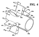
図4を参照すると、ストラット構造64の構成は、本発明の1つの態様を示している。第1のフラップ部分80aのフラップ角θの周方向は、連続するストラット構造64A〜64Fの第1のフラップ部分80aの位置を比較すれば分かるように、周方向で隣接する第1のフラップ部分80aに関して、交互になっているすなわち弦軸線ACの反対側に位置している(図8も参照)。同様に、第1のフラップ部分80aに対して反対に向けられた第2のフラップ部分80bのフラップ角φの周方向は、連続するストラット構造64A〜64Fの第2のフラップ部分80bの位置を比較すれば分かるように、周方向に隣接する第2のフラップ部分80bに関して交互になっている(図8も参照)。
Referring to FIG. 4, the configuration of the
図8を参照すると、図4のストラット構造の構成のための第1および第2のフラップ80a,80bの配置は、ストラット構造64の下流において旋回流、すなわち逆回転の渦を提供するように設計されており、ストラット構造64は、流れ矢印84OUTによって示された半径方向外方への移動と、流れ矢印84INによって示された半径方向内方への移動とを生ぜしめ、その結果、流れの混合を生ぜしめ、速度分布をより均一にする。例えば、ディフューザシェル52におけるよりもハブ58においてより高い流速を有する、ハブにおける強い流れの場合、フラップ部分80a,80bによって提供される流れ混合は、より低速の流れをディフューザシェル52から内方へ移動させ、より高速の流れをハブ52から外方へ移動させて、ディフューザ40を通過する流れにおける速度のばらつきを減じる。特に、前述の後縁フラップ80は、ディフューザシェル52への改良された付着、およびハブ58に隣接した領域における強い流れの増大した外方への混合とともに、より強い外径流れ分布を提供するように、ハブにおける強い流れを変化させることができる。
Referring to FIG. 8, the arrangement of the first and
図4の構成において、図8の構成のように、エンジンの前側から下流方向を見たときに、反時計回り方向に傾斜させられたフラップ80a,80bを、正の角度を有すると呼んでもよく、時計回り方向に傾斜させられたフラップ80a,80bを、負の角度を有すると呼んでもよい。正および負の角度についてのこの慣例は、エンジンの前側から見たときに、反時計回り方向に回転するロータを有するエンジンに関して行われる。
In the configuration of FIG. 4, the
図5は、代替的な構成を示している。第1のフラップ部分80aのためのフラップ角φの周方向は、全て同じ(正の)方向に、弦軸線ACに関して同じ角度で向けられており、第2のフラップ部分80bのフラップ角θは、全て同じ(負の)方向に、弦軸線ACに関して同じ角度で向けられている。例示された構成では、第1のフラップ部分80aは、弦軸線ACの一方の側へ傾斜させられており、第2のフラップ部分80bは、弦軸線ACの反対側へ傾斜させられている。図5の構成は、図4について説明した構成よりも少ない半径方向混合を提供するかもしれないが、エンジンのタービンセクションから出てくる流れの特性に応じて、異なる混合効果が望ましい場合もあることが理解されるであろう。
FIG. 5 shows an alternative configuration. Circumferential direction of the flap angle φ for the
さらに、上記の説明は、排ガスの典型的な、ハブにおける強い流れに関するものであるが、フラップ部分80a,80bの構成は、ハブ58に隣接する排ガスのより弱い流れなど、その他の流れ条件に対応するように提供されてもよいことが理解されるであろう。
Furthermore, while the above description relates to a typical exhaust gas strong flow in the hub, the configuration of the
後縁フラップ80は、ストラットシールド68の上流端部74における前縁から後縁フラップ80の後縁までの、ストラットシールド68および後縁フラップ80が組み合わされた軸方向範囲の全長の実質的な部分を形成している。例えば、後縁フラップ80は全長の約20%〜40%であってもよく、より好適には、全長の約25%〜30%であってもよい。
The trailing
フラップ部分80a,80bの角度φ,θは、弦軸線ACに関して反対方向に同じ値を有してもよいし、または異なる値を有してもよい。特に、周方向で隣接するストラット構造64の間の間隔は、半径方向外方に向かって増大しているので、所望のスワール条件が、第2のフラップ部分80bを第1のフラップ部分80aの角度φよりも大きな角度θに位置決めすることを必要とすることがある。さらに、フラップ部分80a,80bが両方とも、弦軸線ACの同じ側へ、ただしフラップ部分80a,80bの位置が角度φ,θの異なる値を規定しながら延びていてもよいことが理解されるべきである。
また、フラップ部分80a,80bは、ストラットシールド68の下流端部76の内側および外側のスパンの部分のみに沿って形成されていてもよい。例えば、本発明の範囲において、各フラップ部分80aおよび80bは、中間位置82から半径方向に、それぞれハブ58およびディフューザシェル52に向かう距離の一部だけ延びていてもよい。
Further, the
図6は、後縁フラップ80に対する選択的な変更を示している。スプリッタプレート86は、第1および第2のフラップ部分80a,80bの間の中間位置82に設けられてもよい。スプリッタプレート86は、ほぼ平坦なディバイダであり、軸方向および周方向に延びる平面に位置しており、半径方向流れを制限し、かつ第1および第2のフラップ部分80a,80bの間の機械的剛性を高める。スプリッタプレート86の平面は、ストラットシールド68のスパン方向または半径方向に対して垂直に延びている。加えて、スプリッタプレート86は、フラップ部分80a,80bの角度位置にほぼ一致する外縁部86a,86bを有する三角形の構成を備えて形成されてもよく、好適には、溶接結合などによってフラップ部分80a,80bに取り付けられ、これによって後縁フラップ80の剛性を増大させる。
FIG. 6 shows a selective change to the trailing
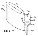
図7は、後縁フラップ80の代替的な構成を示している。後縁フラップ80は、第1のフラップ部分80aおよび第2のフラップ部分80bの双方を形成する連続的な材料ストリップ88から形成されてもよい。特に、材料ストリップ88は、第1のフラップ部分80aによって規定された角度から第2のフラップ部分80bによって規定された角度への滑らかな移行部を規定する、中間位置82における曲がった移行領域80cを備えて形成されてもよい。
FIG. 7 shows an alternative configuration of the trailing
図9を参照すると、後縁フラップ80に対する選択的な変更が示されており、この場合、フラップ部分80a,80bはストラットシールド68に対して可動である。例示された実施の形態では、フラップ部分80a,80bは、回転軸APを中心として回転運動するように支持されている。各フラップ部分80a,80bは、図1に概略的に示されたアクチュエータ90a,90bによって示されているようなそれぞれのアクチュエータによって、回転運動するように作動させられてよい。アクチュエータ90a,90bは、ピボットリンク92a,92bによってフラップ部分80a,80bに接続されていてもよいし、1つの作動されるテールセクション用のアクチュエータを示している米国特許第6792758号明細書に示されているように、公知のアクチュエータおよびリンク構造を有してもよい。この特許は、引用によりその全体が本明細書に組み込まれる。フラップ部分80a,80bは、例えば、共通の回転軸APを中心とする回転運動のために、ストラットシールド68の下流端部76を半径方向に通って延びるそれぞれの同心状のピボットロッド94a,94bによって支持されているか、または別々の回転軸を有するピボットエレメントによって支持されていてもよい。第1のフラップ部分80aは全て、1つのアクチュエータによって同時に移動するようにリンクされていてもよいし、第2のフラップ部分80bは全て、1つのアクチュエータによって同時に移動するようにリンクされていてもよいし、それぞれのフラップ部分80a,80bの間のリンクは、米国特許第6792758号明細書に示されたものと同様の形式で構成されていてもよい。
Referring to FIG. 9, a selective change to the trailing
可動なフラップ部分80a,80bは、ディフューザ40に流入する排ガスの効率的な混合を提供するために、エンジンの作動条件の変化に応答して作動させられてもよい。例えば、フラップ部分80a,80bは、ベース負荷運転の間は、ディフューザ40を通る排ガスの効率的な膨張を提供する初期位置に配置されてよく、フラップ部分80a,80bは、エンジンの部分負荷運転の間または非設計周囲空気入口温度条件の間は、ディフューザ40を通る排ガスの効率的な膨張を提供する第2の位置に配置転換されてもよい。
The
図9に示されたストラット構造64の構成は、ストラットシールド68の側部78a,78bによって形成された輪郭の続きとして形成されたフラップ部分80a,80bを示している。図3〜図5に関して説明されているような、所定の位置に永久に固定されたフラップ部分80a,80bを有するストラット構造64は、ストラットシールド68とフラップ部分80a,80bとの間に類似の連続的な輪郭を備えて形成されてもよいことにも注意すべきである。
The configuration of the
本発明の特定の実施の形態について例示および説明してきたが、本発明の思想および範囲から逸脱することなく様々なその他の変更および改変をなし得ることは当業者には明らかであろう。したがって、本発明の範囲内の全てのこのような変更および改変を添付の請求項に包含するように意図されている。 While particular embodiments of the present invention have been illustrated and described, it would be obvious to those skilled in the art that various other changes and modifications can be made without departing from the spirit and scope of the invention. Accordingly, it is intended to embrace all such changes and modifications as fall within the scope of the invention.
Claims (18)
一対の同心状に間隔を置いて配置されたリングと、
前記リングの間に半径方向に延びた、該リングを接続および支持する複数のストラット構造であって、該ストラット構造は、回転ブレードの最終列の下流に支持され、かつ本体部分を有しており、該本体部分は、エンジンを通る軸方向ガス流の方向に、延在した弦寸法を有しており、前記本体部分の上流端部から前記ストラット構造の下流端部に向かって下流方向へ延びる弦軸線を規定している、ストラット構造と、
各本体部分の下流端部に配置された後縁フラップであって、該後縁フラップは、第1および第2のスパン方向部分を有しており、前記第1のスパン方向部分は、前記本体部分の前記弦軸線に対して所定の角度で流れを方向付けるように向けられており、前記第2のスパン方向部分は、前記第1のスパン方向部分の角度とは異なる角度である方向に流れを方向付けるように向けられている、後縁フラップと、
を備えることを特徴とする、ガスタービンエンジン。 In a gas turbine engine having a turbine exhaust section,
A pair of concentrically spaced rings;
A plurality of strut structures extending radially between the rings for connecting and supporting the rings, the strut structures being supported downstream of the last row of rotating blades and having a body portion The body portion has a chord dimension extending in the direction of axial gas flow through the engine and extends downstream from the upstream end of the body portion toward the downstream end of the strut structure. A strut structure defining the chord axis;
A trailing edge flap disposed at a downstream end of each body portion, the trailing edge flap having first and second span direction portions, wherein the first span direction portion is the body portion. Directed to direct flow at a predetermined angle with respect to the chord axis of the portion, the second span direction portion flowing in a direction that is different from the angle of the first span direction portion. A trailing edge flap that is oriented to direct the
A gas turbine engine comprising:
環状ガス通路を形成する内側シュラウドおよび外側シュラウドと、
前記内側シュラウドを前記外側シュラウドに接続し、かつ回転ブレードの最終列の下流において前記ガス通路内に配置された複数のストラットと、
前記ストラットを包囲する翼形のシールドであって、各シールドは、上流の前縁を有する本体を有し、該本体は、前記シールドの前記前縁から下流端部に向かって下流軸方向へ延びる弦軸線を規定している、翼形のシールドと、
各シールドの前記下流端部に配置された後縁フラップであって、該後縁フラップは、第1および第2のスパン方向部分を有しており、前記第1のスパン方向部分は、前記本体の前記弦軸線に対して所定の角度で流れを方向付けるように向けられており、前記第2のスパン方向部分は、前記第1のスパン方向部分の角度とは異なる角度である方向に流れを方向付けるように向けられている、後縁フラップと、
を備えることを特徴とする、排気ディフューザ。 An exhaust diffuser in a gas turbine engine,
An inner shroud and an outer shroud forming an annular gas passage;
A plurality of struts connecting the inner shroud to the outer shroud and disposed in the gas passage downstream of the last row of rotating blades;
An airfoil shield surrounding the struts, each shield having a body having an upstream leading edge, the body extending in a downstream axial direction from the leading edge of the shield toward a downstream end. An airfoil shield defining the chord axis, and
A trailing edge flap disposed at the downstream end of each shield, the trailing edge flap having first and second spanning portions, wherein the first spanning portion is the body; Directed to direct flow at a predetermined angle with respect to the chord axis, wherein the second span direction portion is directed in a direction that is different from the angle of the first span direction portion. A trailing edge flap, oriented to direct,
An exhaust diffuser characterized by comprising:
Applications Claiming Priority (3)
| Application Number | Priority Date | Filing Date | Title |
|---|---|---|---|
| US14/033,788 | 2013-09-23 | ||
| US14/033,788 US9494053B2 (en) | 2013-09-23 | 2013-09-23 | Diffuser with strut-induced vortex mixing |
| PCT/US2014/052436 WO2015041801A2 (en) | 2013-09-23 | 2014-08-25 | Diffuser with strut-induced vortex mixing |
Publications (2)
| Publication Number | Publication Date |
|---|---|
| JP2016535826A true JP2016535826A (en) | 2016-11-17 |
| JP2016535826A5 JP2016535826A5 (en) | 2017-09-28 |
Family
ID=51535531
Family Applications (1)
| Application Number | Title | Priority Date | Filing Date |
|---|---|---|---|
| JP2016516585A Ceased JP2016535826A (en) | 2013-09-23 | 2014-08-25 | Diffuser for mixing vortices produced by struts |
Country Status (5)
| Country | Link |
|---|---|
| US (1) | US9494053B2 (en) |
| EP (1) | EP3049662A2 (en) |
| JP (1) | JP2016535826A (en) |
| CN (1) | CN105579694B (en) |
| WO (1) | WO2015041801A2 (en) |
Cited By (2)
| Publication number | Priority date | Publication date | Assignee | Title |
|---|---|---|---|---|
| CN111927582A (en) * | 2020-09-10 | 2020-11-13 | 杭州汽轮机股份有限公司 | Exhaust casing of industrial steam turbine |
| CN111927581A (en) * | 2020-09-08 | 2020-11-13 | 杭州汽轮机股份有限公司 | Multi-surface supported welding exhaust cylinder of industrial steam turbine |
Families Citing this family (12)
| Publication number | Priority date | Publication date | Assignee | Title |
|---|---|---|---|---|
| US10151325B2 (en) * | 2015-04-08 | 2018-12-11 | General Electric Company | Gas turbine diffuser strut including a trailing edge flap and methods of assembling the same |
| US10259565B2 (en) | 2016-08-11 | 2019-04-16 | General Electric Company | Inlet assembly for an aircraft aft fan |
| US10252790B2 (en) | 2016-08-11 | 2019-04-09 | General Electric Company | Inlet assembly for an aircraft aft fan |
| US10253779B2 (en) | 2016-08-11 | 2019-04-09 | General Electric Company | Inlet guide vane assembly for reducing airflow swirl distortion of an aircraft aft fan |
| US10704418B2 (en) | 2016-08-11 | 2020-07-07 | General Electric Company | Inlet assembly for an aircraft aft fan |
| US20190353054A1 (en) * | 2017-01-19 | 2019-11-21 | Siemens Aktiengesellschaft | Exhaust system for a gas turbine engine |
| US10563513B2 (en) * | 2017-12-19 | 2020-02-18 | United Technologies Corporation | Variable inlet guide vane |
| FR3078205B1 (en) * | 2018-02-16 | 2020-02-28 | IFP Energies Nouvelles | ELECTRIC MACHINE WITH STATOR GRID COMPRISING AERODYNAMIC APPENDICES |
| KR102403823B1 (en) * | 2019-12-13 | 2022-05-30 | 두산에너빌리티 주식회사 | Strut structure with strip for exhaust diffuser and gas turbine having the same |
| FR3105315B1 (en) * | 2019-12-18 | 2022-02-18 | Safran Aircraft Engines | COMPRESSOR MODULE FOR TURBOMACHINE |
| DE102020203547A1 (en) * | 2020-03-19 | 2021-09-23 | Siemens Aktiengesellschaft | Method of customizing a turbine assembly, fairing, multi-fairing kit, usage and diffuser |
| JP2022126239A (en) * | 2021-02-18 | 2022-08-30 | 三菱重工コンプレッサ株式会社 | gas expander |
Citations (5)
| Publication number | Priority date | Publication date | Assignee | Title |
|---|---|---|---|---|
| JP2004100615A (en) * | 2002-09-11 | 2004-04-02 | Mitsubishi Heavy Ind Ltd | Strut structure of axial-flow turbine |
| US20040088989A1 (en) * | 2002-11-07 | 2004-05-13 | Siemens Westinghouse Power Corporation | Variable exhaust struts shields |
| US20080121301A1 (en) * | 2004-04-09 | 2008-05-29 | Norris Thomas R | Externally Mounted Vortex Generators for Flow Duct Passage |
| JP2008157110A (en) * | 2006-12-25 | 2008-07-10 | Mitsubishi Heavy Ind Ltd | Exhaust strut |
| JP2009002332A (en) * | 2007-06-20 | 2009-01-08 | United Technol Corp <Utc> | Inlet guide vane flap, fan section, and control method for inlet guide vane flap system of varied form |
Family Cites Families (17)
| Publication number | Priority date | Publication date | Assignee | Title |
|---|---|---|---|---|
| US3618700A (en) * | 1970-06-15 | 1971-11-09 | Boeing Co | Retracted noise suppression system |
| GB2114669B (en) * | 1982-02-12 | 1985-01-16 | Rolls Royce | Gas turbine engine bearing support structure |
| EP0581978B1 (en) | 1992-08-03 | 1996-01-03 | Asea Brown Boveri Ag | Multi-zone diffuser for turbomachine |
| DE19641725A1 (en) | 1996-10-10 | 1998-04-16 | Asea Brown Boveri | Gas turbine with sequential combustion |
| GB0314123D0 (en) | 2003-06-18 | 2003-07-23 | Rolls Royce Plc | A gas turbine engine |
| US6997676B2 (en) | 2004-03-10 | 2006-02-14 | General Electric Company | Bifurcated outlet guide vanes |
| US7114911B2 (en) | 2004-08-25 | 2006-10-03 | General Electric Company | Variable camber and stagger airfoil and method |
| US7549839B2 (en) | 2005-10-25 | 2009-06-23 | United Technologies Corporation | Variable geometry inlet guide vane |
| US8348600B2 (en) | 2008-05-27 | 2013-01-08 | United Technologies Corporation | Gas turbine engine having controllable inlet guide vanes |
| US8061983B1 (en) | 2008-06-20 | 2011-11-22 | Florida Turbine Technoligies, Inc. | Exhaust diffuser strut with stepped trailing edge |
| US8333552B2 (en) | 2008-06-20 | 2012-12-18 | General Electric Company | Combined acoustic absorber and heat exchanging outlet guide vanes |
| US8647057B2 (en) | 2009-06-02 | 2014-02-11 | Siemens Energy, Inc. | Turbine exhaust diffuser with a gas jet producing a coanda effect flow control |
| US20110232291A1 (en) | 2010-03-26 | 2011-09-29 | General Electric Company | System and method for an exhaust diffuser |
| EP2559851A1 (en) | 2011-08-19 | 2013-02-20 | Siemens Aktiengesellschaft | Exhaust diffuser and method for manufacturing an exhaust diffuser |
| US20140064955A1 (en) * | 2011-09-14 | 2014-03-06 | General Electric Company | Guide vane assembly for a gas turbine engine |
| US9032721B2 (en) | 2011-12-14 | 2015-05-19 | Siemens Energy, Inc. | Gas turbine engine exhaust diffuser including circumferential vane |
| US9957823B2 (en) * | 2014-01-24 | 2018-05-01 | United Technologies Corporation | Virtual multi-stream gas turbine engine |
-
2013
- 2013-09-23 US US14/033,788 patent/US9494053B2/en not_active Expired - Fee Related
-
2014
- 2014-08-25 EP EP14762151.0A patent/EP3049662A2/en not_active Withdrawn
- 2014-08-25 JP JP2016516585A patent/JP2016535826A/en not_active Ceased
- 2014-08-25 CN CN201480052154.3A patent/CN105579694B/en not_active Expired - Fee Related
- 2014-08-25 WO PCT/US2014/052436 patent/WO2015041801A2/en active Application Filing
Patent Citations (5)
| Publication number | Priority date | Publication date | Assignee | Title |
|---|---|---|---|---|
| JP2004100615A (en) * | 2002-09-11 | 2004-04-02 | Mitsubishi Heavy Ind Ltd | Strut structure of axial-flow turbine |
| US20040088989A1 (en) * | 2002-11-07 | 2004-05-13 | Siemens Westinghouse Power Corporation | Variable exhaust struts shields |
| US20080121301A1 (en) * | 2004-04-09 | 2008-05-29 | Norris Thomas R | Externally Mounted Vortex Generators for Flow Duct Passage |
| JP2008157110A (en) * | 2006-12-25 | 2008-07-10 | Mitsubishi Heavy Ind Ltd | Exhaust strut |
| JP2009002332A (en) * | 2007-06-20 | 2009-01-08 | United Technol Corp <Utc> | Inlet guide vane flap, fan section, and control method for inlet guide vane flap system of varied form |
Cited By (2)
| Publication number | Priority date | Publication date | Assignee | Title |
|---|---|---|---|---|
| CN111927581A (en) * | 2020-09-08 | 2020-11-13 | 杭州汽轮机股份有限公司 | Multi-surface supported welding exhaust cylinder of industrial steam turbine |
| CN111927582A (en) * | 2020-09-10 | 2020-11-13 | 杭州汽轮机股份有限公司 | Exhaust casing of industrial steam turbine |
Also Published As
| Publication number | Publication date |
|---|---|
| WO2015041801A2 (en) | 2015-03-26 |
| CN105579694B (en) | 2018-09-21 |
| US9494053B2 (en) | 2016-11-15 |
| CN105579694A (en) | 2016-05-11 |
| WO2015041801A3 (en) | 2015-06-18 |
| US20150086339A1 (en) | 2015-03-26 |
| EP3049662A2 (en) | 2016-08-03 |
Similar Documents
| Publication | Publication Date | Title |
|---|---|---|
| JP2016535826A (en) | Diffuser for mixing vortices produced by struts | |
| JP6059424B2 (en) | Curved contour axial direction-radial diffuser | |
| JP6877985B2 (en) | Turbomachinery and turbine nozzles for it | |
| JP5995958B2 (en) | Sealing device for turbomachine turbine nozzle | |
| JP6409072B2 (en) | Exhaust gas diffuser with main and small struts | |
| US9726197B2 (en) | Turbomachine element | |
| JP2016205382A (en) | Shroud assembly and shroud for gas turbine engine | |
| JP3564420B2 (en) | gas turbine | |
| JP2016535826A5 (en) | ||
| US20220106907A1 (en) | Turbine engine with struts | |
| JP6971564B2 (en) | Turbomachinery and turbine nozzles for it | |
| JP2019056370A (en) | Intersage seal assembly for counter rotating turbine | |
| JP2015532699A (en) | Gas turbine engine having a radial diffuser and a shortened middle section | |
| CN107091120B (en) | Turbine blade centroid migration method and system | |
| JP2015526691A (en) | Gas turbine engine having a shortened middle section | |
| JP2013151934A (en) | Turbine exhaust diffuser system | |
| US9689312B2 (en) | Gas turbine engine component | |
| WO2018159681A1 (en) | Turbine and gas turbine | |
| US20170074101A1 (en) | Axial turbo machine | |
| JP2018115656A (en) | Strut for exhaust frame of turbine system | |
| CA2963517A1 (en) | Gas turbine engine transition duct and turbine center frame | |
| CN103061831B (en) | The system and method for the some of integrated turbine | |
| US20190353054A1 (en) | Exhaust system for a gas turbine engine | |
| JP2004263602A (en) | Nozzle blade, moving blade, and turbine stage of axial-flow turbine | |
| JP6449218B2 (en) | Transition ducts, turbines, and gas turbine engines |
Legal Events
| Date | Code | Title | Description |
|---|---|---|---|
| A521 | Request for written amendment filed |
Free format text: JAPANESE INTERMEDIATE CODE: A523 Effective date: 20170818 |
|
| A621 | Written request for application examination |
Free format text: JAPANESE INTERMEDIATE CODE: A621 Effective date: 20170818 |
|
| A131 | Notification of reasons for refusal |
Free format text: JAPANESE INTERMEDIATE CODE: A131 Effective date: 20180702 |
|
| A977 | Report on retrieval |
Free format text: JAPANESE INTERMEDIATE CODE: A971007 Effective date: 20180628 |
|
| A601 | Written request for extension of time |
Free format text: JAPANESE INTERMEDIATE CODE: A601 Effective date: 20181002 |
|
| A601 | Written request for extension of time |
Free format text: JAPANESE INTERMEDIATE CODE: A601 Effective date: 20181203 |
|
| A01 | Written decision to grant a patent or to grant a registration (utility model) |
Free format text: JAPANESE INTERMEDIATE CODE: A01 Effective date: 20190304 |
|
| A045 | Written measure of dismissal of application [lapsed due to lack of payment] |
Free format text: JAPANESE INTERMEDIATE CODE: A045 Effective date: 20190729 |