JP2016533017A - Metal-supported solid oxide fuel cell - Google Patents
Metal-supported solid oxide fuel cell Download PDFInfo
- Publication number
- JP2016533017A JP2016533017A JP2016539627A JP2016539627A JP2016533017A JP 2016533017 A JP2016533017 A JP 2016533017A JP 2016539627 A JP2016539627 A JP 2016539627A JP 2016539627 A JP2016539627 A JP 2016539627A JP 2016533017 A JP2016533017 A JP 2016533017A
- Authority
- JP
- Japan
- Prior art keywords
- oxide
- copper
- nickel
- anode
- fuel cell
- Prior art date
- Legal status (The legal status is an assumption and is not a legal conclusion. Google has not performed a legal analysis and makes no representation as to the accuracy of the status listed.)
- Withdrawn
Links
- 239000000446 fuel Substances 0.000 title claims abstract description 75
- 239000007787 solid Substances 0.000 title claims abstract description 14
- PXHVJJICTQNCMI-UHFFFAOYSA-N Nickel Chemical compound [Ni] PXHVJJICTQNCMI-UHFFFAOYSA-N 0.000 claims abstract description 83
- CETPSERCERDGAM-UHFFFAOYSA-N ceric oxide Chemical compound O=[Ce]=O CETPSERCERDGAM-UHFFFAOYSA-N 0.000 claims abstract description 69
- 229910000422 cerium(IV) oxide Inorganic materials 0.000 claims abstract description 68
- 239000003792 electrolyte Substances 0.000 claims abstract description 60
- QPLDLSVMHZLSFG-UHFFFAOYSA-N Copper oxide Chemical compound [Cu]=O QPLDLSVMHZLSFG-UHFFFAOYSA-N 0.000 claims abstract description 59
- 229910052761 rare earth metal Inorganic materials 0.000 claims abstract description 50
- 150000002910 rare earth metals Chemical class 0.000 claims abstract description 48
- 239000005751 Copper oxide Substances 0.000 claims abstract description 44
- 239000010949 copper Substances 0.000 claims abstract description 44
- 229910000431 copper oxide Inorganic materials 0.000 claims abstract description 44
- 229910000480 nickel oxide Inorganic materials 0.000 claims abstract description 44
- GNRSAWUEBMWBQH-UHFFFAOYSA-N oxonickel Chemical compound [Ni]=O GNRSAWUEBMWBQH-UHFFFAOYSA-N 0.000 claims abstract description 44
- 229910052802 copper Inorganic materials 0.000 claims abstract description 43
- RYGMFSIKBFXOCR-UHFFFAOYSA-N Copper Chemical compound [Cu] RYGMFSIKBFXOCR-UHFFFAOYSA-N 0.000 claims abstract description 42
- 238000000034 method Methods 0.000 claims abstract description 40
- 239000000758 substrate Substances 0.000 claims abstract description 39
- 229910052759 nickel Inorganic materials 0.000 claims abstract description 38
- 239000002184 metal Substances 0.000 claims abstract description 37
- 229910052751 metal Inorganic materials 0.000 claims abstract description 36
- 239000002131 composite material Substances 0.000 claims abstract description 25
- 238000010304 firing Methods 0.000 claims abstract description 18
- 239000000976 ink Substances 0.000 claims description 31
- 229910001220 stainless steel Inorganic materials 0.000 claims description 18
- 239000002245 particle Substances 0.000 claims description 17
- 229910044991 metal oxide Inorganic materials 0.000 claims description 15
- 150000004706 metal oxides Chemical class 0.000 claims description 14
- 239000000843 powder Substances 0.000 claims description 12
- BERDEBHAJNAUOM-UHFFFAOYSA-N copper(i) oxide Chemical compound [Cu]O[Cu] BERDEBHAJNAUOM-UHFFFAOYSA-N 0.000 claims description 8
- 238000001035 drying Methods 0.000 claims description 7
- 229910021526 gadolinium-doped ceria Inorganic materials 0.000 claims description 7
- YOCUPQPZWBBYIX-UHFFFAOYSA-N copper nickel Chemical compound [Ni].[Cu] YOCUPQPZWBBYIX-UHFFFAOYSA-N 0.000 claims description 6
- LDSIKPHVUGHOOI-UHFFFAOYSA-N copper;oxonickel Chemical compound [Ni].[Cu]=O LDSIKPHVUGHOOI-UHFFFAOYSA-N 0.000 claims description 6
- 238000009826 distribution Methods 0.000 claims description 5
- 238000010438 heat treatment Methods 0.000 claims description 5
- 229910000881 Cu alloy Inorganic materials 0.000 claims description 3
- 238000005245 sintering Methods 0.000 description 27
- 239000000919 ceramic Substances 0.000 description 24
- 239000001301 oxygen Substances 0.000 description 12
- 229910052760 oxygen Inorganic materials 0.000 description 12
- 239000012071 phase Substances 0.000 description 12
- 230000002829 reductive effect Effects 0.000 description 12
- 239000011195 cermet Substances 0.000 description 11
- 239000012298 atmosphere Substances 0.000 description 10
- 239000000463 material Substances 0.000 description 10
- 230000008018 melting Effects 0.000 description 9
- 238000002844 melting Methods 0.000 description 9
- MCMNRKCIXSYSNV-UHFFFAOYSA-N Zirconium dioxide Chemical compound O=[Zr]=O MCMNRKCIXSYSNV-UHFFFAOYSA-N 0.000 description 8
- QVGXLLKOCUKJST-UHFFFAOYSA-N atomic oxygen Chemical compound [O] QVGXLLKOCUKJST-UHFFFAOYSA-N 0.000 description 8
- 230000015572 biosynthetic process Effects 0.000 description 8
- 230000008859 change Effects 0.000 description 8
- 238000004519 manufacturing process Methods 0.000 description 8
- 230000009467 reduction Effects 0.000 description 8
- UFHFLCQGNIYNRP-UHFFFAOYSA-N Hydrogen Chemical compound [H][H] UFHFLCQGNIYNRP-UHFFFAOYSA-N 0.000 description 7
- 239000001257 hydrogen Substances 0.000 description 7
- 229910052739 hydrogen Inorganic materials 0.000 description 7
- 239000000203 mixture Substances 0.000 description 7
- 230000003647 oxidation Effects 0.000 description 7
- 238000007254 oxidation reaction Methods 0.000 description 7
- 238000007906 compression Methods 0.000 description 6
- 238000005336 cracking Methods 0.000 description 6
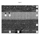
- 238000001878 scanning electron micrograph Methods 0.000 description 6
- 238000012360 testing method Methods 0.000 description 6
- 238000012546 transfer Methods 0.000 description 6
- 229910002484 Ce0.9Gd0.1O1.95 Inorganic materials 0.000 description 5
- 229910000831 Steel Inorganic materials 0.000 description 5
- WGLPBDUCMAPZCE-UHFFFAOYSA-N Trioxochromium Chemical compound O=[Cr](=O)=O WGLPBDUCMAPZCE-UHFFFAOYSA-N 0.000 description 5
- 230000008901 benefit Effects 0.000 description 5
- 239000011230 binding agent Substances 0.000 description 5
- 229910052804 chromium Inorganic materials 0.000 description 5
- 239000011651 chromium Substances 0.000 description 5
- 229910000423 chromium oxide Inorganic materials 0.000 description 5
- 230000006378 damage Effects 0.000 description 5
- 239000002001 electrolyte material Substances 0.000 description 5
- 239000011888 foil Substances 0.000 description 5
- 229910003455 mixed metal oxide Inorganic materials 0.000 description 5
- -1 oxygen ion Chemical class 0.000 description 5
- 230000008569 process Effects 0.000 description 5
- 239000010959 steel Substances 0.000 description 5
- IJGRMHOSHXDMSA-UHFFFAOYSA-N Atomic nitrogen Chemical compound N#N IJGRMHOSHXDMSA-UHFFFAOYSA-N 0.000 description 4
- 239000004215 Carbon black (E152) Substances 0.000 description 4
- 239000003054 catalyst Substances 0.000 description 4
- 229910017052 cobalt Inorganic materials 0.000 description 4
- 239000010941 cobalt Substances 0.000 description 4
- GUTLYIVDDKVIGB-UHFFFAOYSA-N cobalt atom Chemical compound [Co] GUTLYIVDDKVIGB-UHFFFAOYSA-N 0.000 description 4
- 229910000428 cobalt oxide Inorganic materials 0.000 description 4
- IVMYJDGYRUAWML-UHFFFAOYSA-N cobalt(ii) oxide Chemical compound [Co]=O IVMYJDGYRUAWML-UHFFFAOYSA-N 0.000 description 4
- 229930195733 hydrocarbon Natural products 0.000 description 4
- 150000002430 hydrocarbons Chemical class 0.000 description 4
- 238000002161 passivation Methods 0.000 description 4
- 239000002904 solvent Substances 0.000 description 4
- 229910002076 stabilized zirconia Inorganic materials 0.000 description 4
- 238000000629 steam reforming Methods 0.000 description 4
- 230000009286 beneficial effect Effects 0.000 description 3
- 150000001768 cations Chemical class 0.000 description 3
- 229910000420 cerium oxide Inorganic materials 0.000 description 3
- 230000006835 compression Effects 0.000 description 3
- 238000013461 design Methods 0.000 description 3
- 238000006056 electrooxidation reaction Methods 0.000 description 3
- 239000010408 film Substances 0.000 description 3
- 239000002737 fuel gas Substances 0.000 description 3
- XEEYBQQBJWHFJM-UHFFFAOYSA-N iron Substances [Fe] XEEYBQQBJWHFJM-UHFFFAOYSA-N 0.000 description 3
- 230000001590 oxidative effect Effects 0.000 description 3
- BMMGVYCKOGBVEV-UHFFFAOYSA-N oxo(oxoceriooxy)cerium Chemical compound [Ce]=O.O=[Ce]=O BMMGVYCKOGBVEV-UHFFFAOYSA-N 0.000 description 3
- 238000007650 screen-printing Methods 0.000 description 3
- VYZAMTAEIAYCRO-UHFFFAOYSA-N Chromium Chemical compound [Cr] VYZAMTAEIAYCRO-UHFFFAOYSA-N 0.000 description 2
- WHXSMMKQMYFTQS-UHFFFAOYSA-N Lithium Chemical compound [Li] WHXSMMKQMYFTQS-UHFFFAOYSA-N 0.000 description 2
- PACGUUNWTMTWCF-UHFFFAOYSA-N [Sr].[La] Chemical compound [Sr].[La] PACGUUNWTMTWCF-UHFFFAOYSA-N 0.000 description 2
- 238000001354 calcination Methods 0.000 description 2
- 230000015556 catabolic process Effects 0.000 description 2
- 229910010293 ceramic material Inorganic materials 0.000 description 2
- 229910052963 cobaltite Inorganic materials 0.000 description 2
- 150000001875 compounds Chemical class 0.000 description 2
- 238000006731 degradation reaction Methods 0.000 description 2
- 238000003487 electrochemical reaction Methods 0.000 description 2
- 230000002708 enhancing effect Effects 0.000 description 2
- CMIHHWBVHJVIGI-UHFFFAOYSA-N gadolinium(iii) oxide Chemical compound [O-2].[O-2].[O-2].[Gd+3].[Gd+3] CMIHHWBVHJVIGI-UHFFFAOYSA-N 0.000 description 2
- 238000001764 infiltration Methods 0.000 description 2
- 230000008595 infiltration Effects 0.000 description 2
- 239000010416 ion conductor Substances 0.000 description 2
- 230000037427 ion transport Effects 0.000 description 2
- 229910052744 lithium Inorganic materials 0.000 description 2
- 230000007246 mechanism Effects 0.000 description 2
- 239000011533 mixed conductor Substances 0.000 description 2
- 229910052757 nitrogen Inorganic materials 0.000 description 2
- RVTZCBVAJQQJTK-UHFFFAOYSA-N oxygen(2-);zirconium(4+) Chemical compound [O-2].[O-2].[Zr+4] RVTZCBVAJQQJTK-UHFFFAOYSA-N 0.000 description 2
- 238000002360 preparation method Methods 0.000 description 2
- 238000010405 reoxidation reaction Methods 0.000 description 2
- 239000004065 semiconductor Substances 0.000 description 2
- 239000000126 substance Substances 0.000 description 2
- 229910001928 zirconium oxide Inorganic materials 0.000 description 2
- OKTJSMMVPCPJKN-UHFFFAOYSA-N Carbon Chemical compound [C] OKTJSMMVPCPJKN-UHFFFAOYSA-N 0.000 description 1
- 229910052684 Cerium Inorganic materials 0.000 description 1
- 229910002132 La0.6Sr0.4Co0.2Fe0.8O3-δ Inorganic materials 0.000 description 1
- 229910002131 La0.6Sr0.4Co0.2Fe0.8O3–δ Inorganic materials 0.000 description 1
- 229910002130 La0.6Sr0.4Co0.2Fe0.8O3−δ Inorganic materials 0.000 description 1
- 229910052777 Praseodymium Inorganic materials 0.000 description 1
- 229910052772 Samarium Inorganic materials 0.000 description 1
- 241000968352 Scandia <hydrozoan> Species 0.000 description 1
- VYPSYNLAJGMNEJ-UHFFFAOYSA-N Silicium dioxide Chemical compound O=[Si]=O VYPSYNLAJGMNEJ-UHFFFAOYSA-N 0.000 description 1
- RTAQQCXQSZGOHL-UHFFFAOYSA-N Titanium Chemical compound [Ti] RTAQQCXQSZGOHL-UHFFFAOYSA-N 0.000 description 1
- 230000001154 acute effect Effects 0.000 description 1
- 239000000853 adhesive Substances 0.000 description 1
- 230000001070 adhesive effect Effects 0.000 description 1
- 238000007605 air drying Methods 0.000 description 1
- 229910052782 aluminium Inorganic materials 0.000 description 1
- XAGFODPZIPBFFR-UHFFFAOYSA-N aluminium Chemical compound [Al] XAGFODPZIPBFFR-UHFFFAOYSA-N 0.000 description 1
- 239000010405 anode material Substances 0.000 description 1
- 230000004888 barrier function Effects 0.000 description 1
- 238000005452 bending Methods 0.000 description 1
- 238000003490 calendering Methods 0.000 description 1
- 229910052799 carbon Inorganic materials 0.000 description 1
- 230000003197 catalytic effect Effects 0.000 description 1
- 238000004814 ceramic processing Methods 0.000 description 1
- ZMIGMASIKSOYAM-UHFFFAOYSA-N cerium Chemical compound [Ce][Ce][Ce][Ce][Ce][Ce][Ce][Ce][Ce][Ce][Ce][Ce][Ce][Ce][Ce][Ce][Ce][Ce][Ce][Ce][Ce][Ce][Ce][Ce][Ce][Ce][Ce][Ce][Ce][Ce][Ce][Ce][Ce][Ce][Ce][Ce][Ce][Ce] ZMIGMASIKSOYAM-UHFFFAOYSA-N 0.000 description 1
- 238000012512 characterization method Methods 0.000 description 1
- 238000006243 chemical reaction Methods 0.000 description 1
- 238000007796 conventional method Methods 0.000 description 1
- 150000001879 copper Chemical class 0.000 description 1
- 239000011258 core-shell material Substances 0.000 description 1
- 238000000354 decomposition reaction Methods 0.000 description 1
- 230000000593 degrading effect Effects 0.000 description 1
- 238000000151 deposition Methods 0.000 description 1
- 230000001627 detrimental effect Effects 0.000 description 1
- 238000010586 diagram Methods 0.000 description 1
- 229910003460 diamond Inorganic materials 0.000 description 1
- 239000010432 diamond Substances 0.000 description 1
- 238000009792 diffusion process Methods 0.000 description 1
- 239000002270 dispersing agent Substances 0.000 description 1
- 238000005553 drilling Methods 0.000 description 1
- 230000000694 effects Effects 0.000 description 1
- 238000001652 electrophoretic deposition Methods 0.000 description 1
- 238000005516 engineering process Methods 0.000 description 1
- 230000005496 eutectics Effects 0.000 description 1
- 238000011156 evaluation Methods 0.000 description 1
- 238000004299 exfoliation Methods 0.000 description 1
- 238000009472 formulation Methods 0.000 description 1
- 239000007789 gas Substances 0.000 description 1
- 238000011065 in-situ storage Methods 0.000 description 1
- 238000009776 industrial production Methods 0.000 description 1
- 239000004615 ingredient Substances 0.000 description 1
- 238000009413 insulation Methods 0.000 description 1
- 229910052742 iron Inorganic materials 0.000 description 1
- 229910052746 lanthanum Inorganic materials 0.000 description 1
- 230000000670 limiting effect Effects 0.000 description 1
- 239000007791 liquid phase Substances 0.000 description 1
- FUJCRWPEOMXPAD-UHFFFAOYSA-N lithium oxide Chemical compound [Li+].[Li+].[O-2] FUJCRWPEOMXPAD-UHFFFAOYSA-N 0.000 description 1
- 229910001947 lithium oxide Inorganic materials 0.000 description 1
- WPBNNNQJVZRUHP-UHFFFAOYSA-L manganese(2+);methyl n-[[2-(methoxycarbonylcarbamothioylamino)phenyl]carbamothioyl]carbamate;n-[2-(sulfidocarbothioylamino)ethyl]carbamodithioate Chemical compound [Mn+2].[S-]C(=S)NCCNC([S-])=S.COC(=O)NC(=S)NC1=CC=CC=C1NC(=S)NC(=O)OC WPBNNNQJVZRUHP-UHFFFAOYSA-L 0.000 description 1
- 239000002923 metal particle Substances 0.000 description 1
- 230000003278 mimic effect Effects 0.000 description 1
- 238000002156 mixing Methods 0.000 description 1
- 229910052758 niobium Inorganic materials 0.000 description 1
- 239000010955 niobium Substances 0.000 description 1
- GUCVJGMIXFAOAE-UHFFFAOYSA-N niobium atom Chemical compound [Nb] GUCVJGMIXFAOAE-UHFFFAOYSA-N 0.000 description 1
- 239000011368 organic material Substances 0.000 description 1
- TWNQGVIAIRXVLR-UHFFFAOYSA-N oxo(oxoalumanyloxy)alumane Chemical compound O=[Al]O[Al]=O TWNQGVIAIRXVLR-UHFFFAOYSA-N 0.000 description 1
- HJGMWXTVGKLUAQ-UHFFFAOYSA-N oxygen(2-);scandium(3+) Chemical compound [O-2].[O-2].[O-2].[Sc+3].[Sc+3] HJGMWXTVGKLUAQ-UHFFFAOYSA-N 0.000 description 1
- 230000036961 partial effect Effects 0.000 description 1
- 230000010287 polarization Effects 0.000 description 1
- 229920005596 polymer binder Polymers 0.000 description 1
- 239000002491 polymer binding agent Substances 0.000 description 1
- 238000010248 power generation Methods 0.000 description 1
- 238000007639 printing Methods 0.000 description 1
- 238000010926 purge Methods 0.000 description 1
- 230000009257 reactivity Effects 0.000 description 1
- 238000002407 reforming Methods 0.000 description 1
- 238000011160 research Methods 0.000 description 1
- 230000000452 restraining effect Effects 0.000 description 1
- 150000003839 salts Chemical class 0.000 description 1
- FKTOIHSPIPYAPE-UHFFFAOYSA-N samarium(iii) oxide Chemical compound [O-2].[O-2].[O-2].[Sm+3].[Sm+3] FKTOIHSPIPYAPE-UHFFFAOYSA-N 0.000 description 1
- 238000013341 scale-up Methods 0.000 description 1
- 229910052814 silicon oxide Inorganic materials 0.000 description 1
- 238000007569 slipcasting Methods 0.000 description 1
- 239000003381 stabilizer Substances 0.000 description 1
- 239000010935 stainless steel Substances 0.000 description 1
- 238000010345 tape casting Methods 0.000 description 1
- 239000010409 thin film Substances 0.000 description 1
- 239000010936 titanium Substances 0.000 description 1
- 229910052719 titanium Inorganic materials 0.000 description 1
- 230000003313 weakening effect Effects 0.000 description 1
- 239000000080 wetting agent Substances 0.000 description 1
- RUDFQVOCFDJEEF-UHFFFAOYSA-N yttrium(III) oxide Inorganic materials [O-2].[O-2].[O-2].[Y+3].[Y+3] RUDFQVOCFDJEEF-UHFFFAOYSA-N 0.000 description 1
Images


Classifications
-
- H—ELECTRICITY
- H01—ELECTRIC ELEMENTS
- H01M—PROCESSES OR MEANS, e.g. BATTERIES, FOR THE DIRECT CONVERSION OF CHEMICAL ENERGY INTO ELECTRICAL ENERGY
- H01M4/00—Electrodes
- H01M4/86—Inert electrodes with catalytic activity, e.g. for fuel cells
- H01M4/88—Processes of manufacture
- H01M4/8825—Methods for deposition of the catalytic active composition
- H01M4/8828—Coating with slurry or ink
-
- H—ELECTRICITY
- H01—ELECTRIC ELEMENTS
- H01M—PROCESSES OR MEANS, e.g. BATTERIES, FOR THE DIRECT CONVERSION OF CHEMICAL ENERGY INTO ELECTRICAL ENERGY
- H01M4/00—Electrodes
- H01M4/86—Inert electrodes with catalytic activity, e.g. for fuel cells
- H01M4/8647—Inert electrodes with catalytic activity, e.g. for fuel cells consisting of more than one material, e.g. consisting of composites
- H01M4/8652—Inert electrodes with catalytic activity, e.g. for fuel cells consisting of more than one material, e.g. consisting of composites as mixture
-
- H—ELECTRICITY
- H01—ELECTRIC ELEMENTS
- H01M—PROCESSES OR MEANS, e.g. BATTERIES, FOR THE DIRECT CONVERSION OF CHEMICAL ENERGY INTO ELECTRICAL ENERGY
- H01M4/00—Electrodes
- H01M4/86—Inert electrodes with catalytic activity, e.g. for fuel cells
- H01M4/90—Selection of catalytic material
- H01M4/9016—Oxides, hydroxides or oxygenated metallic salts
-
- C—CHEMISTRY; METALLURGY
- C23—COATING METALLIC MATERIAL; COATING MATERIAL WITH METALLIC MATERIAL; CHEMICAL SURFACE TREATMENT; DIFFUSION TREATMENT OF METALLIC MATERIAL; COATING BY VACUUM EVAPORATION, BY SPUTTERING, BY ION IMPLANTATION OR BY CHEMICAL VAPOUR DEPOSITION, IN GENERAL; INHIBITING CORROSION OF METALLIC MATERIAL OR INCRUSTATION IN GENERAL
- C23C—COATING METALLIC MATERIAL; COATING MATERIAL WITH METALLIC MATERIAL; SURFACE TREATMENT OF METALLIC MATERIAL BY DIFFUSION INTO THE SURFACE, BY CHEMICAL CONVERSION OR SUBSTITUTION; COATING BY VACUUM EVAPORATION, BY SPUTTERING, BY ION IMPLANTATION OR BY CHEMICAL VAPOUR DEPOSITION, IN GENERAL
- C23C18/00—Chemical coating by decomposition of either liquid compounds or solutions of the coating forming compounds, without leaving reaction products of surface material in the coating; Contact plating
- C23C18/02—Chemical coating by decomposition of either liquid compounds or solutions of the coating forming compounds, without leaving reaction products of surface material in the coating; Contact plating by thermal decomposition
-
- H—ELECTRICITY
- H01—ELECTRIC ELEMENTS
- H01M—PROCESSES OR MEANS, e.g. BATTERIES, FOR THE DIRECT CONVERSION OF CHEMICAL ENERGY INTO ELECTRICAL ENERGY
- H01M4/00—Electrodes
- H01M4/86—Inert electrodes with catalytic activity, e.g. for fuel cells
- H01M4/8605—Porous electrodes
- H01M4/8621—Porous electrodes containing only metallic or ceramic material, e.g. made by sintering or sputtering
-
- H—ELECTRICITY
- H01—ELECTRIC ELEMENTS
- H01M—PROCESSES OR MEANS, e.g. BATTERIES, FOR THE DIRECT CONVERSION OF CHEMICAL ENERGY INTO ELECTRICAL ENERGY
- H01M4/00—Electrodes
- H01M4/86—Inert electrodes with catalytic activity, e.g. for fuel cells
- H01M4/8647—Inert electrodes with catalytic activity, e.g. for fuel cells consisting of more than one material, e.g. consisting of composites
- H01M4/8657—Inert electrodes with catalytic activity, e.g. for fuel cells consisting of more than one material, e.g. consisting of composites layered
-
- H—ELECTRICITY
- H01—ELECTRIC ELEMENTS
- H01M—PROCESSES OR MEANS, e.g. BATTERIES, FOR THE DIRECT CONVERSION OF CHEMICAL ENERGY INTO ELECTRICAL ENERGY
- H01M4/00—Electrodes
- H01M4/86—Inert electrodes with catalytic activity, e.g. for fuel cells
- H01M4/88—Processes of manufacture
- H01M4/8803—Supports for the deposition of the catalytic active composition
-
- H—ELECTRICITY
- H01—ELECTRIC ELEMENTS
- H01M—PROCESSES OR MEANS, e.g. BATTERIES, FOR THE DIRECT CONVERSION OF CHEMICAL ENERGY INTO ELECTRICAL ENERGY
- H01M4/00—Electrodes
- H01M4/86—Inert electrodes with catalytic activity, e.g. for fuel cells
- H01M4/88—Processes of manufacture
- H01M4/8825—Methods for deposition of the catalytic active composition
- H01M4/8828—Coating with slurry or ink
- H01M4/8832—Ink jet printing
-
- H—ELECTRICITY
- H01—ELECTRIC ELEMENTS
- H01M—PROCESSES OR MEANS, e.g. BATTERIES, FOR THE DIRECT CONVERSION OF CHEMICAL ENERGY INTO ELECTRICAL ENERGY
- H01M4/00—Electrodes
- H01M4/86—Inert electrodes with catalytic activity, e.g. for fuel cells
- H01M4/88—Processes of manufacture
- H01M4/8878—Treatment steps after deposition of the catalytic active composition or after shaping of the electrode being free-standing body
- H01M4/8882—Heat treatment, e.g. drying, baking
- H01M4/8885—Sintering or firing
-
- H—ELECTRICITY
- H01—ELECTRIC ELEMENTS
- H01M—PROCESSES OR MEANS, e.g. BATTERIES, FOR THE DIRECT CONVERSION OF CHEMICAL ENERGY INTO ELECTRICAL ENERGY
- H01M4/00—Electrodes
- H01M4/86—Inert electrodes with catalytic activity, e.g. for fuel cells
- H01M4/88—Processes of manufacture
- H01M4/8878—Treatment steps after deposition of the catalytic active composition or after shaping of the electrode being free-standing body
- H01M4/8896—Pressing, rolling, calendering
-
- H—ELECTRICITY
- H01—ELECTRIC ELEMENTS
- H01M—PROCESSES OR MEANS, e.g. BATTERIES, FOR THE DIRECT CONVERSION OF CHEMICAL ENERGY INTO ELECTRICAL ENERGY
- H01M4/00—Electrodes
- H01M4/86—Inert electrodes with catalytic activity, e.g. for fuel cells
- H01M4/90—Selection of catalytic material
- H01M4/9016—Oxides, hydroxides or oxygenated metallic salts
- H01M4/9025—Oxides specially used in fuel cell operating at high temperature, e.g. SOFC
- H01M4/9033—Complex oxides, optionally doped, of the type M1MeO3, M1 being an alkaline earth metal or a rare earth, Me being a metal, e.g. perovskites
-
- H—ELECTRICITY
- H01—ELECTRIC ELEMENTS
- H01M—PROCESSES OR MEANS, e.g. BATTERIES, FOR THE DIRECT CONVERSION OF CHEMICAL ENERGY INTO ELECTRICAL ENERGY
- H01M4/00—Electrodes
- H01M4/86—Inert electrodes with catalytic activity, e.g. for fuel cells
- H01M4/90—Selection of catalytic material
- H01M4/9041—Metals or alloys
- H01M4/905—Metals or alloys specially used in fuel cell operating at high temperature, e.g. SOFC
- H01M4/9066—Metals or alloys specially used in fuel cell operating at high temperature, e.g. SOFC of metal-ceramic composites or mixtures, e.g. cermets
-
- H—ELECTRICITY
- H01—ELECTRIC ELEMENTS
- H01M—PROCESSES OR MEANS, e.g. BATTERIES, FOR THE DIRECT CONVERSION OF CHEMICAL ENERGY INTO ELECTRICAL ENERGY
- H01M8/00—Fuel cells; Manufacture thereof
- H01M8/02—Details
- H01M8/0202—Collectors; Separators, e.g. bipolar separators; Interconnectors
- H01M8/0204—Non-porous and characterised by the material
- H01M8/0206—Metals or alloys
-
- H—ELECTRICITY
- H01—ELECTRIC ELEMENTS
- H01M—PROCESSES OR MEANS, e.g. BATTERIES, FOR THE DIRECT CONVERSION OF CHEMICAL ENERGY INTO ELECTRICAL ENERGY
- H01M8/00—Fuel cells; Manufacture thereof
- H01M8/10—Fuel cells with solid electrolytes
- H01M8/12—Fuel cells with solid electrolytes operating at high temperature, e.g. with stabilised ZrO2 electrolyte
- H01M8/1213—Fuel cells with solid electrolytes operating at high temperature, e.g. with stabilised ZrO2 electrolyte characterised by the electrode/electrolyte combination or the supporting material
- H01M8/1226—Fuel cells with solid electrolytes operating at high temperature, e.g. with stabilised ZrO2 electrolyte characterised by the electrode/electrolyte combination or the supporting material characterised by the supporting layer
-
- H—ELECTRICITY
- H01—ELECTRIC ELEMENTS
- H01M—PROCESSES OR MEANS, e.g. BATTERIES, FOR THE DIRECT CONVERSION OF CHEMICAL ENERGY INTO ELECTRICAL ENERGY
- H01M8/00—Fuel cells; Manufacture thereof
- H01M8/24—Grouping of fuel cells, e.g. stacking of fuel cells
- H01M8/241—Grouping of fuel cells, e.g. stacking of fuel cells with solid or matrix-supported electrolytes
- H01M8/2425—High-temperature cells with solid electrolytes
- H01M8/2432—Grouping of unit cells of planar configuration
-
- H—ELECTRICITY
- H01—ELECTRIC ELEMENTS
- H01M—PROCESSES OR MEANS, e.g. BATTERIES, FOR THE DIRECT CONVERSION OF CHEMICAL ENERGY INTO ELECTRICAL ENERGY
- H01M4/00—Electrodes
- H01M4/86—Inert electrodes with catalytic activity, e.g. for fuel cells
- H01M2004/8678—Inert electrodes with catalytic activity, e.g. for fuel cells characterised by the polarity
- H01M2004/8684—Negative electrodes
-
- H—ELECTRICITY
- H01—ELECTRIC ELEMENTS
- H01M—PROCESSES OR MEANS, e.g. BATTERIES, FOR THE DIRECT CONVERSION OF CHEMICAL ENERGY INTO ELECTRICAL ENERGY
- H01M8/00—Fuel cells; Manufacture thereof
- H01M8/10—Fuel cells with solid electrolytes
- H01M8/12—Fuel cells with solid electrolytes operating at high temperature, e.g. with stabilised ZrO2 electrolyte
- H01M2008/1293—Fuel cells with solid oxide electrolytes
-
- H—ELECTRICITY
- H01—ELECTRIC ELEMENTS
- H01M—PROCESSES OR MEANS, e.g. BATTERIES, FOR THE DIRECT CONVERSION OF CHEMICAL ENERGY INTO ELECTRICAL ENERGY
- H01M4/00—Electrodes
- H01M4/86—Inert electrodes with catalytic activity, e.g. for fuel cells
- H01M4/88—Processes of manufacture
- H01M4/8878—Treatment steps after deposition of the catalytic active composition or after shaping of the electrode being free-standing body
- H01M4/8882—Heat treatment, e.g. drying, baking
- H01M4/8885—Sintering or firing
- H01M4/8889—Cosintering or cofiring of a catalytic active layer with another type of layer
-
- Y—GENERAL TAGGING OF NEW TECHNOLOGICAL DEVELOPMENTS; GENERAL TAGGING OF CROSS-SECTIONAL TECHNOLOGIES SPANNING OVER SEVERAL SECTIONS OF THE IPC; TECHNICAL SUBJECTS COVERED BY FORMER USPC CROSS-REFERENCE ART COLLECTIONS [XRACs] AND DIGESTS
- Y02—TECHNOLOGIES OR APPLICATIONS FOR MITIGATION OR ADAPTATION AGAINST CLIMATE CHANGE
- Y02E—REDUCTION OF GREENHOUSE GAS [GHG] EMISSIONS, RELATED TO ENERGY GENERATION, TRANSMISSION OR DISTRIBUTION
- Y02E60/00—Enabling technologies; Technologies with a potential or indirect contribution to GHG emissions mitigation
- Y02E60/30—Hydrogen technology
- Y02E60/50—Fuel cells
Landscapes
- Chemical & Material Sciences (AREA)
- Engineering & Computer Science (AREA)
- Chemical Kinetics & Catalysis (AREA)
- General Chemical & Material Sciences (AREA)
- Electrochemistry (AREA)
- Manufacturing & Machinery (AREA)
- Life Sciences & Earth Sciences (AREA)
- Sustainable Energy (AREA)
- Sustainable Development (AREA)
- Materials Engineering (AREA)
- Thermal Sciences (AREA)
- Physics & Mathematics (AREA)
- Composite Materials (AREA)
- Ceramic Engineering (AREA)
- Organic Chemistry (AREA)
- Metallurgy (AREA)
- Mechanical Engineering (AREA)
- Inert Electrodes (AREA)
- Fuel Cell (AREA)
Abstract
金属支持固体酸化物燃料電池を形成する方法であって:a)酸化ニッケル、酸化銅、及び希土類ドープされたセリアを含む環境に優しいアノード層を、金属基材に適用すること;b)環境に優しいアノード層を焼成して、ニッケル、銅、及び希土類ドープされたセリアの酸化物を含む複合材を形成すること;c)電解質を提供すること;並びにd)カソードを提供することを含む、方法。アノード、カソード、及び電解質を含む金属支持固体酸化物燃料電池であって、アノードは、ニッケル、銅、及び希土類ドープされたセリアを含む、金属支持固体酸化物燃料電池、これらの燃料電池の燃料電池スタック、及びその使用。A method of forming a metal-supported solid oxide fuel cell comprising: a) applying an environmentally friendly anode layer comprising nickel oxide, copper oxide, and rare earth doped ceria to a metal substrate; b) to the environment Firing a gentle anode layer to form a composite comprising nickel, copper, and rare earth doped ceria oxides; c) providing an electrolyte; and d) providing a cathode. . Metal supported solid oxide fuel cells comprising an anode, a cathode, and an electrolyte, wherein the anode comprises nickel, copper, and rare earth doped ceria, fuel cells of these fuel cells Stack and its use.
Description
本発明は、金属支持固体酸化物燃料電池(SOFC)、燃料電池の形成方法、及びその使用に関する。本発明は、特に、アノードがニッケル及び銅を含む、金属支持固体酸化物燃料電池に関する。 The present invention relates to a metal-supported solid oxide fuel cell (SOFC), a method of forming a fuel cell, and uses thereof. The invention particularly relates to a metal-supported solid oxide fuel cell in which the anode comprises nickel and copper.
SOFCは、燃料ガス(通常、水素ベース)の電気化学的酸化による電気エネルギーを生成する電気化学装置である。装置は、一般に、その電解質として酸素イオン伝導性金属酸化物由来のセラミックを用いた、セラミックベースである。ほとんどのセラミック酸素イオン導体(たとえば、ドープされた酸化ジルコニウム、又はドープされた酸化セリウム)が、(酸化セリウムベースの電解質について)500℃、又は(酸化ジルコニウムベースのセラミックスについて)600℃を上回る温度における、技術的に重要なイオン伝導率を実証するのみであるように、SOFCは高温で作動する。 A SOFC is an electrochemical device that generates electrical energy by electrochemical oxidation of a fuel gas (usually hydrogen-based). The device is generally a ceramic base, using a ceramic derived from an oxygen ion conducting metal oxide as its electrolyte. Most ceramic oxygen ion conductors (eg doped zirconium oxide or doped cerium oxide) at temperatures above 500 ° C. (for cerium oxide based electrolytes) or above 600 ° C. (for zirconium oxide based ceramics) The SOFC operates at high temperatures so that it only demonstrates technically important ionic conductivity.
他の燃料電池と同じように、SOFCは、燃料が酸化されるアノード、及び酸素が還元されるカソードを含む。これらの電極は、電気化学反応を触媒することができなければならず、作動(陽極側での還元、カソード側での酸化)温度における、それらのそれぞれの雰囲気下で安定でなければならず、かつ、電気化学反応によって作り出される電流が電極−電解質界面から引き出されるように、電子を伝導することができなければならない。 As with other fuel cells, the SOFC includes an anode where the fuel is oxidized and a cathode where the oxygen is reduced. These electrodes must be able to catalyze electrochemical reactions and must be stable under their respective atmospheres at the operating (reduction on the anode side, oxidation on the cathode side) temperature, And it must be able to conduct electrons so that the current created by the electrochemical reaction is drawn from the electrode-electrolyte interface.
広範囲な研究にもかかわらず、アノードにとって重要な特性の組合せを有する材料を見つけることは困難であることが分かっている。長年にわたって、技術水準のSOFCアノードは、金属相としてニッケル、及びセラミック相として電解質材料(通常、イットリア又はスカンジア安定化ジルコニア)を有する、多孔質セラミック−金属(サーメット)複合構造から構成され、一般的ではないがドープされたセリアベースの電解質材料、例えばガドリニア又はサマリアドープされたセリアも使われている。この構造では、ニッケルが触媒の役割を担い、ニッケルの体積分率は、隣接する金属ネットワークが形成される程度に十分に高く、したがって必要な電子伝導率を提供する。電解質材料は、機械的構造を提供し、アノードと電解質との間の結合を強化し、アノード−電解質界面領域をアノード内にいくらかの距離延在させる、隣接するセラミック骨格をアノードに形成する。 Despite extensive research, it has proven difficult to find materials with a combination of properties that are important for the anode. Over the years, state-of-the-art SOFC anodes have been constructed from a porous ceramic-metal (cermet) composite structure with nickel as the metal phase and an electrolyte material (usually yttria or scandia stabilized zirconia) as the ceramic phase, However, doped ceria-based electrolyte materials such as gadolinia or samaria doped ceria are also used. In this structure, nickel serves as a catalyst, and the volume fraction of nickel is high enough to form an adjacent metal network, thus providing the necessary electronic conductivity. The electrolyte material provides a mechanical structure, strengthens the bond between the anode and the electrolyte, and forms an adjacent ceramic framework at the anode that extends the anode-electrolyte interface region some distance into the anode.
これらのサーメットアノードの周知の限界は、電池作動温度において、アノードの金属ニッケルは還元性雰囲気においてのみ安定である、ということである。これは通常、燃料ガスによって提供されるので、通常、運転下でアノードは安定である。しかしながら、作動温度でSOFCへの燃料ガスの供給を中断すると、アノード内の雰囲気は酸化状態になる。これらの条件下で、金属ニッケルは、酸化ニッケルへと酸化される。焼結した酸化ニッケルの還元によって形成された金属ニッケルは、それが形成された元の酸化ニッケルと同じモルホロジーへと酸化されて戻らないので、この酸化は、約40%を超える体積増加を伴う。その代わり、それは元の酸化ニッケルより大きい体積を占めるメソ多孔質体を生じる。再酸化におけるこの体積変化は、アノード構造内に大きな応力を生じる可能性があり、このことは、アノードのクラック、及びSOFC電池の潜在的な破壊に繋がる可能性がある。 A well-known limitation of these cermet anodes is that at battery operating temperatures, the metallic nickel of the anode is stable only in a reducing atmosphere. Since this is usually provided by fuel gas, the anode is usually stable under operation. However, if the supply of fuel gas to the SOFC is interrupted at the operating temperature, the atmosphere in the anode becomes oxidized. Under these conditions, metallic nickel is oxidized to nickel oxide. This oxidation is accompanied by a volume increase of more than about 40% because the metallic nickel formed by reduction of the sintered nickel oxide does not oxidize back to the same morphology as the original nickel oxide from which it was formed. Instead, it yields a mesoporous body that occupies a larger volume than the original nickel oxide. This volume change in reoxidation can create significant stresses in the anode structure, which can lead to anode cracking and potential destruction of the SOFC cell.
SOFCシステムは、一般に、予想外の燃料中断、例えばシステムのどこかに安全性の理由でシステムの緊急停止を必要とする破損が生じた場合に、アノードの上の還元性雰囲気を維持する、錯体及び高価なパージガスシステムの存在を必要とするので、多くのSOFC電池がこのタイプのダメージを受けずに複数の酸化還元(REDOX)サイクルを耐えることができないということは、発電用SOFC技術の広範囲にわたる商業的採用を抑制する主な要因であった。 SOFC systems generally have a complex that maintains a reducing atmosphere above the anode in the event of an unexpected fuel interruption, for example, a failure somewhere in the system that requires an emergency shutdown of the system for safety reasons. And the need for expensive purge gas systems, the fact that many SOFC cells cannot withstand multiple redox (REDOX) cycles without suffering this type of damage is a widespread of power generation SOFC technology It was the main factor restraining commercial adoption.
不充分なREDOX安定性の問題は、特に、現在最も一般的な形態のSOFC電池であるアノード支持燃料電池において深刻である。電解質は非構造体であるところ、アノード支持は、用いられる電解質(例えば安定化ジルコニア)の層を非常に薄く(20μm未満)することを可能にするので有益である。これは、電解質支持電池の場合よりも低い温度範囲(800℃〜1000℃ではなく、650〜850℃)における作動を可能にする。電解質支持燃料電池において、酸素イオン輸送に対する電解質の抵抗は、電解質厚に反比例するので、電解質層の厚みによって生じる抵抗は、温度に伴う抵抗の指数関数的な低下を利用し、作動温度を上昇させることによって克服される。アノード支持電池ではより薄い層を使用することができるので、作動温度を低下させることができ、このことは、SOFCシステムにおいてより低コストの材料の使用を促進し、様々な材料分解機構、例えば金属成分の酸化の速度を低減するので一般的に望ましい。 The problem of insufficient REDOX stability is particularly acute in anode supported fuel cells, which are currently the most common form of SOFC cells. Where the electrolyte is unstructured, the anode support is beneficial because it allows the layer of electrolyte used (eg, stabilized zirconia) to be very thin (less than 20 μm). This allows operation in a lower temperature range (650-850 ° C., not 800-1000 ° C.) than in the case of electrolyte-supported batteries. In an electrolyte-supported fuel cell, the resistance of the electrolyte to oxygen ion transport is inversely proportional to the thickness of the electrolyte, so that the resistance caused by the thickness of the electrolyte layer increases the operating temperature using an exponential decrease in resistance with temperature. Can be overcome. Since thinner layers can be used in anode supported cells, the operating temperature can be lowered, which facilitates the use of lower cost materials in SOFC systems and various material decomposition mechanisms such as metal This is generally desirable because it reduces the rate of oxidation of the components.
これらの利点にもかかわらず、アノード支持電池ではアノードがSOFC電池の構造的支持体であり、応力誘発性クラッキングは電池の完全な破壊に繋がる可能性があるため、電池は、繰り返される酸化還元サイクル上、破滅的に故障する傾向が高い。 In spite of these advantages, in anode supported cells, the anode is the structural support for SOFC cells, and stress-induced cracking can lead to complete destruction of the cells, so that the cells are subject to repeated redox cycles. Above, there is a high tendency to catastrophic failure.
開発者による多大な努力にもかかわらず、ニッケルの比較的低コスト性と、水素の電気化学的酸化及び炭化水素燃料供給の水蒸気改質の両方のための高い触媒活性と、高い電子伝導率とを兼ねる、適切な材料が未だ開発されていないので、ニッケルに対する代替は、広範囲にわたって採用されなかった。 Despite great efforts by the developers, the relatively low cost of nickel, high catalytic activity for both electrochemical oxidation of hydrogen and steam reforming of hydrocarbon fuel feeds, and high electronic conductivity As no suitable material has yet been developed, no alternative to nickel has been widely adopted.
Gorte等(米国特許出願公開第2005/227133号公報A1、米国特許第7,014,942号明細書B2)は、部分的又は完全にニッケルを置換した、SOFCアノードにおける銅の使用を報告した。銅は、特に炭化水素燃料からの炭素の形成を触媒しないので、アノードの電子伝導相として有利である。しかしながら、銅は水素の電気化学的酸化及び炭化水素燃料の水蒸気改質にとって劣った触媒であるので、Gorteらによって試験された銅アノードでは、十分な電極性能を達成するのに追加の触媒、例えばセリアを必要とした。従来のSOFC用途において銅を用いることの他の問題は、銅金属及び酸化銅の融点が低い(それぞれ1084℃、及び1326℃)ということである。サーメットアノードは、典型的に、金属酸化物粉末及び電解質粉末の混合物を、空気中で1200〜1500℃で焼結し、続いてSOFCの最初の運転で水素を使用して金属酸化物を金属へ還元することによって形成される。この焼結温度の範囲は、酸化銅の融点の付近又はそれより高く(これに対し酸化ニッケルは1955℃で融解する)、酸化銅相の過剰な焼結につながる。また、従来のSOFC作動温度は、金属銅の融点付近の700〜900℃であり、SOFC作動の間、銅相の焼結につながり、潜在的な性能低下を引き起こす可能性がある。この問題を解決するために、Gorteらは、銅塩の溶液を用いた焼結後浸透工程でアノードに銅を加え、乾燥及び焼結して塩を酸化銅に分解し、それによって酸化銅を高温で焼結する必要性を回避する方法を開発した。しかしながら、浸透工程は、銅サーメットの使用を可能にするものの、工業的製造までスケールアップすることが困難であることがある。銅の他の問題は、ニッケルより反応性が低いにもかかわらず、温度で酸化雰囲気に暴露されると更に酸化するということであり、したがって、銅ベースのアノードもまた酸化還元安定性に欠ける。 Gorte et al. (US Patent Application Publication No. 2005/227133 A1, US Pat. No. 7,014,942 B2) reported the use of copper in SOFC anodes, partially or fully substituted for nickel. Copper is advantageous as the electronically conducting phase of the anode because it does not catalyze the formation of carbon from hydrocarbon fuels in particular. However, since copper is a poor catalyst for electrochemical oxidation of hydrogen and steam reforming of hydrocarbon fuels, copper anodes tested by Gorte et al. Have additional catalysts such as, for example, to achieve sufficient electrode performance Needed ceria. Another problem with using copper in conventional SOFC applications is that the melting points of copper metal and copper oxide are low (1084 ° C. and 1326 ° C., respectively). Cermet anodes typically sinter a mixture of metal oxide powder and electrolyte powder in air at 1200-1500 ° C., followed by hydrogen in the first operation of SOFC to convert the metal oxide to metal. Formed by reduction. This range of sintering temperatures is near or above the melting point of copper oxide (as opposed to nickel oxide melting at 1955 ° C.), leading to excessive sintering of the copper oxide phase. Also, the conventional SOFC operating temperature is 700-900 ° C. near the melting point of metallic copper, which can lead to sintering of the copper phase during SOFC operation and can cause potential performance degradation. To solve this problem, Gorte et al. Added copper to the anode in a post-sintering infiltration process using a solution of copper salt, dried and sintered to decompose the salt into copper oxide, thereby removing the copper oxide. A method has been developed to avoid the need to sinter at high temperatures. However, while the infiltration process allows the use of copper cermet, it can be difficult to scale up to industrial production. Another problem with copper is that it is more reactive when exposed to an oxidizing atmosphere at temperature, albeit less reactive than nickel, and therefore copper-based anodes also lack redox stability.
酸化還元サイクルのダメージ効果を緩和するのに役立つ、SOFCの設計に関する要因があり、要因は:
●アノード支持電池を使用しないこと−したがって、アノードをより薄くすることができる;酸化還元サイクルによる全体的な体積変化及び破滅的クラッキングの危険性を低減する。
●より低温で作動させること−ニッケルの酸化速度は、温度の増加と共に指数的に増加し、300℃超で始まる。作動温度が低ければ低いほど、ニッケルの酸化及び体積膨張の危険性がより少ない。更に、ニッケル粒子は、外表面は急速に酸化するが、粒子のコアは拡散律速でよりゆっくりと酸化する、コアシェル機構をとおして酸化される傾向がある。したがって、より低い温度においては、アノード内のニッケル粒子の全体粒子ではなく外表面だけが再酸化され、体積変化がいくらか低減される傾向がある。
●アノードに隣接するセラミック「骨格」を提供すること−SOFCアノードに使用される電解質ベースのセラミック相は、酸素分圧の変化によってほとんど影響を受けないので、ニッケル相に影響を及ぼす酸化還元サイクルの間、アノードのこの部分は体積が変わらないであろう。したがって、アノード内に焼結された多孔質セラミックネットワークがある場合、アノードの構造的完全性、及び電解質に対する結合が強化されるであろう。
There are SOFC design factors that can help mitigate the damage effects of the redox cycle, including:
Do not use anode-supported cells-therefore the anode can be made thinner; reduce the overall volume change and catastrophic cracking risk due to redox cycles.
• Operating at lower temperatures—The oxidation rate of nickel increases exponentially with increasing temperature and begins above 300 ° C. The lower the operating temperature, the less risk of nickel oxidation and volume expansion. Furthermore, nickel particles tend to oxidize through a core-shell mechanism, where the outer surface oxidizes rapidly, but the core of the particle oxidizes more slowly and diffusion-limited. Thus, at lower temperatures, only the outer surface, rather than the total nickel particles in the anode, are reoxidized and the volume change tends to be somewhat reduced.
• Providing a ceramic “framework” adjacent to the anode—the electrolyte-based ceramic phase used in the SOFC anode is almost unaffected by changes in oxygen partial pressure, so that the redox cycle affects the nickel phase. Meanwhile, this part of the anode will not change volume. Thus, if there is a sintered porous ceramic network within the anode, the structural integrity of the anode and the bond to the electrolyte will be enhanced.
これらの基準を満たす可能性があるSOFC電池の設計は、英国特許第2368450号明細書の出願人によって開示された、金属支持SOFC設計である。このSOFC電池は、構造的支持体としてフェライトステンレススチール箔を使用する。箔はその中心領域において多孔質になっており、燃料がアノードにアクセスすること可能にする。活性電池層(アノード、電解質、及びカソード)は、すべてフィルムとしての基材箔上に堆積される。それは電池のための構造的支持体ではないので、アノードは厚みが約15μmであればよいことを意味する。この電池もまた、標準的な作動温度より非常に低い450〜650℃の温度範囲での作動を可能にする。これは、ジルコニアベースの材料よりも本質的に高い酸素イオン伝導率を有する、酸化セリウム(セリア)ベースのセラミック材料、例えばCGO10(ガドリニウムドープされた酸化セリウム、CGO10について−Ce0.9Gd0.1O1.95)を、酸素イオン伝導性電解質として大部分に用いることにより達成される。英国特許第2456445号明細書に開示されているように、安定化ジルコニアの薄膜を電解質に堆積して、セリアベース電解質の混合イオン−電子伝導率による電池の内部短絡が防止されるが、しかしながら、ジルコニア層は非常に薄いので、その酸素イオン輸送に対する抵抗は、低温作動が妨げられない程度に十分に低い。英国特許第2368450号明細書のSOFC電池は、5〜30μmの厚みを有する厚いフィルムとして製造される、多孔質金属−CGO10複合材サーメットアノードを使用する。アノードは、一般的に、金属酸化物及びCGO10粉末を含むインクをスクリーン印刷することによって堆積され、熱処理によって多孔質セラミック層を形成し、堆積された粉末を共に焼結して、スチール基材に結合した隣接構造を形成する。 An SOFC battery design that may meet these criteria is the metal-supported SOFC design disclosed by the applicant of GB 2368450. This SOFC battery uses ferritic stainless steel foil as a structural support. The foil is porous in its central region, allowing fuel to access the anode. The active cell layers (anode, electrolyte, and cathode) are all deposited on the substrate foil as a film. Since it is not a structural support for the battery, it means that the anode may be about 15 μm thick. This battery also allows operation in the temperature range of 450-650 ° C., much lower than the standard operating temperature. This is a cerium oxide (ceria) based ceramic material, such as CGO10 (gadolinium doped cerium oxide, -Ce 0.9 Gd 0. 1 O 1.95 ) for the most part as an oxygen ion conducting electrolyte. As disclosed in GB 2456445, a thin film of stabilized zirconia is deposited on the electrolyte to prevent internal short circuit of the battery due to the mixed ionic-electron conductivity of the ceria-based electrolyte, however, Since the zirconia layer is very thin, its resistance to oxygen ion transport is low enough that low temperature operation is not hindered. The SOFC battery of GB 2368450 uses a porous metal-CGO10 composite cermet anode, which is manufactured as a thick film having a thickness of 5-30 μm. The anode is typically deposited by screen printing an ink containing metal oxide and CGO10 powder, forming a porous ceramic layer by heat treatment, and sintering the deposited powder together to form a steel substrate. Form a contiguous adjacent structure.
従来のセラミックの処理方法によってフェライトステンレススチール支持体上にセラミック層を堆積することによって、酸化雰囲気における高温で酸化クロムスケールが形成するので、酸化雰囲気において鋼を暴露してもよい最大温度に制限が課される。この上限は、セラミックス焼結に典型的に使用される1200〜1500℃より実質的に低く、そのため、希土類ドープされたセリア電解質を、1100℃未満で、理論密度である96%超まで焼結する、所望の気密な層の形成を促進する方法が開発された(英国特許第2368450号明細書、英国特許第2386126号明細書、及び英国特許第2400486号明細書)。 Depositing a ceramic layer on a ferritic stainless steel support by conventional ceramic processing methods forms a chromium oxide scale at high temperatures in an oxidizing atmosphere, thus limiting the maximum temperature at which steel can be exposed in an oxidizing atmosphere. Imposed. This upper limit is substantially lower than 1200-1500 ° C. typically used for ceramic sintering, so rare earth-doped ceria electrolytes are sintered below 1100 ° C. to a theoretical density of over 96%. , Methods have been developed to promote the formation of the desired hermetic layer (GB 2368450, GB 2386126, and GB 24000486).
驚くべきことに、これらの温度で酸化ニッケル−希土類ドープされたセリア複合材アノードを焼結することは、電解質の焼結よりも困難であることが分かった。これは、2つの異なる酸化物材料の複合材は、単一の相材料よりも焼結しにくいことが分かったからである。したがって、酸化ニッケル又はセラミック単独は、これらの温度で適切に焼結するが、しかしながら、複合材の空気中での焼結は劣っている可能性があり、粒子と弱いセラミック構造との間の弱いネックにつながる可能性がある。酸化還元サイクルの間の体積変化の結果、ニッケル粒子間の弱い結合が破壊されるので、これは酸化還元サイクルの結果として電池の故障につながる可能性がある。これは、アノードから電解質が剥離することにより、最終的に電池の破滅的な故障につながる可能性がある。 Surprisingly, it has been found that sintering nickel oxide-rare earth doped ceria composite anodes at these temperatures is more difficult than electrolyte sintering. This is because it has been found that a composite of two different oxide materials is less likely to sinter than a single phase material. Thus, nickel oxide or ceramic alone will sinter properly at these temperatures, however, the composite may be poorly sintered in air and weak between the particles and the weak ceramic structure. It may lead to a bottleneck. This can lead to cell failure as a result of the redox cycle, as a result of the volume change during the redox cycle, the weak bonds between the nickel particles are broken. This can eventually lead to catastrophic failure of the battery due to the electrolyte peeling from the anode.
電池の酸化還元安定性を改善するために、スチール基材上のセラミック層を焼成することができる温度範囲で、サーメット構造の充分な焼結をすることができる手段を見つけることが望ましい。したがって、アノードが、酸化還元サイクルに対して安定で、作動温度における還元性雰囲気の低下に対してロバストであり、さらに商業的に実現可能な製造方法を用いて行うことができる、金属支持SOFCの調製方法を提供することは有益である。本発明は、この問題及び上記に開示した問題のいくつかの側面を克服する、又は少なくとも改善することを目的とする。 In order to improve the redox stability of the battery, it is desirable to find a means capable of sufficient sintering of the cermet structure in the temperature range where the ceramic layer on the steel substrate can be fired. Thus, the anode of the metal-supported SOFC can be performed using a commercially feasible manufacturing method, where the anode is stable to the redox cycle, robust to reducing reducing atmospheres at operating temperatures. It would be beneficial to provide a method of preparation. The present invention aims to overcome, or at least ameliorate, this problem and some aspects of the problems disclosed above.
したがって、本発明の第一の側面において、金属支持SOFCを形成する方法であって、
a)酸化ニッケル、酸化銅、及び希土類ドープされたセリアを含む環境に優しいアノード層を、金属基材に適用すること;
b)環境に優しいアノード層を焼成して、ニッケル、銅、及び希土類ドープされたセリアの酸化物を含む複合材を形成すること;
c)電解質を提供すること;並びに
d)カソードを提供することを含む、方法が適用される。
Thus, in a first aspect of the present invention, a method for forming a metal-supported SOFC comprising:
a) applying an environmentally friendly anode layer comprising nickel oxide, copper oxide and rare earth doped ceria to the metal substrate;
b) firing an environmentally friendly anode layer to form a composite comprising nickel, copper and rare earth doped ceria oxides;
A method is applied that includes c) providing an electrolyte; and d) providing a cathode.
アノード層内の、一般に酸化銅としての銅の存在は、アノードに、酸化ニッケルと希土類ドープされたセリアとの間の改善された焼結を提供する。これは、アノードのミクロ構造は銅が存在しない場合よりもロバストであり、また、燃料電池の最初の使用において酸化ニッケル及び酸化銅がニッケル及び銅へと還元される間に、又は還元性雰囲気が作動温度で失われた場合、たとえば予期せぬシステム故障及び燃料供給の低下が生じた場合の再酸化におけるあらゆる変化の間に、体積変化がより起こりにくいので、アノード中のセラミック骨格の形成を強化し、酸化還元サイクルに対するアノードの(及び、燃料電池全体としての)安定性を増大する。 The presence of copper, generally as copper oxide, in the anode layer provides the anode with improved sintering between nickel oxide and rare earth doped ceria. This is because the anode microstructure is more robust than in the absence of copper, and during the initial use of the fuel cell, nickel oxide and copper oxide are reduced to nickel and copper, or a reducing atmosphere is present. Enhanced formation of the ceramic framework in the anode as volume changes are less likely to occur during any change in reoxidation if lost at operating temperature, for example, in the event of unexpected system failure and reduced fuel supply And increase the stability of the anode (and the fuel cell as a whole) against the redox cycle.
多くの場合、本発明の方法は、環境に優しいアノード層を100〜300MPaの圧力で圧縮する工程をさらに含む。この圧縮工程は、未焼結の環境に優しいアノード層の密度を上昇させ、本発明の方法で使用される温度で、酸化ニッケル、酸化銅、及び希土類ドープされたセリアの粒子を十分に近接させ効果的に焼結することを保証する。多くの場合、圧縮工程は、プリントした層を加熱する工程と組み合わせて使用し、圧縮の前にインクベースから残留した有機材料を除去し、酸化ニッケル、酸化銅、及び希土類ドープされたセリアを含む、圧縮してもよい環境に優しいアノード層を残す。 In many cases, the method of the present invention further includes the step of compressing the environmentally friendly anode layer at a pressure of 100-300 MPa. This compression step increases the density of the green environmentally friendly anode layer and brings nickel oxide, copper oxide, and rare earth doped ceria particles in close proximity at the temperatures used in the method of the present invention. Ensures effective sintering. Often, the compression process is used in combination with heating the printed layer to remove residual organic material from the ink base prior to compression and includes nickel oxide, copper oxide, and rare earth doped ceria. Leave an environmentally friendly anode layer that may be compressed.
記載されている方法の第一の工程は、環境に優しいアノード層を金属基材に適用することであり、金属基材は、典型的に、ステンレススチール基材であり、特にフェライトステンレススチールは加熱したとき酸化クロム表面不動態層を形成するので、フェライトステンレススチール基材である。この不動態層は、支持体のバルク金属を保護し、アノードと支持体のバルク金属との間に拡散バリヤを提供する。本明細書で用いる用語「支持体」及び「基材」は、金属支持体/基材を意味するものとして交換可能に使用されることを意図する。他の耐熱鋼で共通して形成される酸化アルミニウム又は酸化シリコンとは対照的に、酸化クロム不動態層を形成することは、酸化クロムは高温において絶縁ではなく電子半導体であり、フェライトステンレススチールを燃料電池用途における使用に適するものにするという利点を有する。フェライトステンレススチールは、アルミニウムを含まないフェライトステンレススチール、例えば、安定剤としてのチタン及び/又はニオブを含むフェライトステンレススチールであってもよい。多くの場合、フェライトステンレススチールは、約17.5〜23質量%のCrを含む。具体的には、フェライトステンレススチールは、欧州規格1.4509(17.5〜18.5質量%Cr)及び/又は欧州規格1.4760(22〜23質量%Cr)から選択してもよいが、当業者であれば理解できるように、類似のフェライトステンレススチールの規格を使用してもよい。 The first step of the described method is to apply an environmentally friendly anode layer to the metal substrate, which is typically a stainless steel substrate, especially ferritic stainless steel is heated. When formed, a chromium oxide surface passivation layer is formed, which is a ferritic stainless steel substrate. This passivation layer protects the bulk metal of the support and provides a diffusion barrier between the anode and the bulk metal of the support. The terms “support” and “substrate” as used herein are intended to be used interchangeably to mean a metal support / substrate. In contrast to aluminum oxide or silicon oxide, which is commonly formed in other heat resistant steels, the formation of a chromium oxide passivation layer means that chromium oxide is an electronic semiconductor rather than an insulation at high temperatures, It has the advantage of making it suitable for use in fuel cell applications. The ferritic stainless steel may be ferritic stainless steel that does not contain aluminum, for example ferritic stainless steel with titanium and / or niobium as stabilizers. In many cases, ferritic stainless steel contains about 17.5-23 wt% Cr. Specifically, the ferritic stainless steel may be selected from European standard 1.4509 (17.5 to 18.5 mass% Cr) and / or European standard 1.4760 (22 to 23 mass% Cr). Similar ferritic stainless steel standards may be used, as will be appreciated by those skilled in the art.
基材は、約50〜500μm、多くの場合約100〜400μm、場合によっては約200〜350μmの厚みを有してもよい。基材の厚さは、安定な基材を提供する必要性によって決定され、電池形成又は使用の間にゆがまないが、できるだけ薄くして、燃料とアノードとの間の効果的な接触を可能にする。英国特許第2368450号明細書に記載されているように、この接触は、基材の非多孔質領域に囲まれた多孔性領域であって、アノードがその上に形成される多孔性領域を提供することによって、優れた結果とともに達成することができる。多くの場合、基材の多孔性領域は、基材表面の一方と他方とを流動的に相互接続する複数のつながった開口を含み、多くの場合、これらは均一に間隔を置いて離れ、更に又は代替として約5〜500μm、又は約100〜300μmの横方向寸法を有する。更に、開口は、基材の多孔質領域の約0.1〜5面積%、又は基材の多孔質領域の約0.2〜2面積%を占めてもよい。これらの特徴の各々は、燃料が基材を通ってアノードへと効率的に移動することに寄与し、金属基材に燃料電池を支持させつつ、電池内の電気化学的活性層の厚みを大きく低減することを促進する。 The substrate may have a thickness of about 50-500 μm, often about 100-400 μm, and in some cases about 200-350 μm. The thickness of the substrate is determined by the need to provide a stable substrate and will not distort during cell formation or use, but should be as thin as possible to allow effective contact between the fuel and the anode. To do. As described in GB 2368450, this contact provides a porous region surrounded by a non-porous region of the substrate, on which the anode is formed. Can be achieved with excellent results. Often the porous region of the substrate includes a plurality of connected openings that fluidly interconnect one and the other of the substrate surface, often these are evenly spaced apart, and Alternatively, it has a lateral dimension of about 5-500 μm, or about 100-300 μm. Further, the openings may occupy about 0.1-5 area% of the porous region of the substrate, or about 0.2-2 area% of the porous region of the substrate. Each of these features contributes to the efficient transfer of fuel through the substrate to the anode, increasing the thickness of the electrochemically active layer in the cell while supporting the fuel cell on the metal substrate. Promote reduction.
典型的に、基材は箔であるが、しかしながら焼結基材を使用することもできる。箔の利点は、多孔質領域の構造制御が容易であることである。 Typically, the substrate is a foil, however, a sintered substrate can also be used. The advantage of the foil is that the structure control of the porous region is easy.
環境に優しいアノード層は、一般に、酸化ニッケル、酸化銅、及び希土類ドープされたセリアを含むインクを適用することによって形成されるが、しかしながら、他の方法を用いてもよい。これらの三成分は、一般に、インクベース内に粉末として懸濁しており、インクベースは、一又は複数の揮発性の溶媒、一つ以上の溶解した不揮発性の高分子バインダ、分散剤、湿潤剤、及び他の一般的なインク成分を一般に含む。酸化ニッケル、酸化銅、及び希土類ドープセリアは、多くの場合、0.1〜4μm、又は0.2〜2μm、又は0.7〜1.2μmの粒度分布d90を有する。酸化銅、酸化ニッケル、及び希土類ドープされたセリアの各々の粒度分布及び径自体は異なってもよいが、しかしながら、それらが同じであるか又は同様である場合、粉末の良好な混合、したがってアノードの強い焼結を促進することに役立つので、有益であることがある。インク内により容易に懸濁し、アノード層内の成分のより高い均一性を提供し、高い表面積対体積比を有し、粒子の反応性及び焼結容易性を増大させるので、一般に小さな粒径が選択される。 The environmentally friendly anode layer is generally formed by applying an ink comprising nickel oxide, copper oxide, and rare earth doped ceria, however other methods may be used. These three components are generally suspended as a powder in an ink base, which is composed of one or more volatile solvents, one or more dissolved non-volatile polymeric binders, a dispersant, a wetting agent. , And other common ink ingredients. Nickel oxide, copper oxide, and rare earth-doped ceria often have a particle size distribution d90 of 0.1 to 4 μm, or 0.2 to 2 μm, or 0.7 to 1.2 μm. The particle size distribution and diameter of each of the copper oxide, nickel oxide, and rare earth doped ceria may be different, however, if they are the same or similar, good mixing of the powder, and therefore the anode May be beneficial as it helps to promote strong sintering. Small particle sizes are generally more easily suspended because they suspend more easily in the ink, provide greater uniformity of the components in the anode layer, have a high surface area to volume ratio, and increase particle reactivity and sinterability. Selected.
典型的に、インクは、混合金属酸化物のインク中、30〜70質量%の固形分を含む(すなわち、酸化銅、及び酸化ニッケルの組合せ)。多くの場合、これは35〜45質量%であり、固体の残りは希土類ドープされたセリアである。すなわち、多くの場合、インクの固体は金属酸化物及び希土類ドープされたセリアのみであり、すなわち、多くの場合、アノードは、酸化ニッケル、酸化銅、及び希土類ドープセリアから成り、又は本質的にこれらから成る。多くの場合、インク中の金属酸化物成分は、全金属酸化物の5〜50質量%、多くの場合8〜25質量%の酸化銅を含む。多くの場合、酸化銅は、全金属酸化物の約10質量%、おそらく8又は9〜11又は12質量%であり、したがって、酸化ニッケル対酸化銅の比は、約9:1である。比率は、典型的に20:1〜4:1、多くの場合15:1〜6:1である。これらの酸化銅ドーピングの濃度を選択することによって、金属酸化物の融点を希土類ドープされたセリアを焼結するのに必要な温度未満に低下させず、かつ、燃料が水素であるとき又は燃料電池が水蒸気炭化水素改質であるときのアノードの機能を損なわずに、酸化銅の比較的低い融点が、複合材アノード材料内に強化された焼結を提供することが分かった。 Typically, the ink comprises 30-70 wt% solids in a mixed metal oxide ink (ie, a combination of copper oxide and nickel oxide). Often this is 35-45% by weight and the remainder of the solid is rare earth doped ceria. That is, in many cases, the solids of the ink are only metal oxide and rare earth doped ceria, i.e., the anode often consists of or consists essentially of nickel oxide, copper oxide, and rare earth doped ceria. Become. In many cases, the metal oxide component in the ink comprises 5-50% by weight of the total metal oxide, often 8-25% by weight of copper oxide. Often, the copper oxide is about 10% by weight of the total metal oxide, perhaps 8 or 9-11 or 12%, so the ratio of nickel oxide to copper oxide is about 9: 1. The ratio is typically 20: 1 to 4: 1, often 15: 1 to 6: 1. By selecting these copper oxide doping concentrations, the melting point of the metal oxide is not reduced below the temperature required to sinter the rare earth doped ceria and when the fuel is hydrogen or a fuel cell It has been found that the relatively low melting point of copper oxide provides enhanced sintering within the composite anode material without compromising the function of the anode when is a steam hydrocarbon reforming.
酸化銅(II)は酸化銅(I)よりも高い融点を有し、半導体特性を有するので、多くの場合、酸化銅は酸化銅(II)である。しかしながら、酸化銅(I)は、空気中高温で酸化銅(II)を形成することがあるので、酸化銅(I)を用いてもよい。 Since copper (II) oxide has a higher melting point than copper oxide (I) and has semiconductor properties, in many cases the copper oxide is copper (II) oxide. However, since copper (I) oxide may form copper (II) oxide at high temperature in the air, copper (I) oxide may be used.
多くの例において、希土類ドープされたセリアは、式Ce1−xRExO2−x/2であり、REは希土類、及び0.3≧x≧0.05である。多くの場合、希土類ドープされたセリアは、ガドリニウムドープされた酸化セリウムであり、多くの場合、式Ce0.9Gd0.1O1.95(CGO10)である。これらは、ジルコニアベースの材料を含む多くの電解質材料よりも高い酸素イオン伝導率を有するので、これらの化合物が一般に使われ;これによって、燃料電池が従来のSOFCよりも低い温度で作動することを可能にし、本発明の燃料電池の作動温度範囲は、典型的に450℃〜650℃、多くの場合500℃〜620℃である。より低い温度で燃料電池を作動することは、非還元性雰囲気におけるニッケルの酸化速度が低減され、その結果、粒子の外殻のみが酸化され、アノード内の体積変化を低減し、したがって燃料供給の還元性雰囲気が中断される場合におけるクラッキングの危険性を低減することにつながることを含む、多くの利点を有する。更に、金属支持体の使用が可能になり、電極及び電解質材料は構造的役割をあまり果たさない、あるとしてもほとんど果たさないので、これらを薄層にすることが可能である。更に、これらの温度は銅の融点より充分低く、電池の成分として銅を使用する選択肢を提供する。 In many instances, the rare-earth doped ceria is a formula Ce 1-x RE x O 2 -x / 2, RE is a rare earth, and 0.3 ≧ x ≧ 0.05. Often the rare earth doped ceria is gadolinium doped cerium oxide, often of the formula Ce 0.9 Gd 0.1 O 1.95 (CGO10). These compounds are commonly used because they have higher oxygen ion conductivity than many electrolyte materials, including zirconia-based materials; this allows fuel cells to operate at lower temperatures than conventional SOFCs. The operating temperature range of the fuel cell of the present invention is typically 450 ° C to 650 ° C, often 500 ° C to 620 ° C. Operating the fuel cell at a lower temperature reduces the oxidation rate of nickel in a non-reducing atmosphere, so that only the outer shell of the particles is oxidized, reducing the volume change in the anode and thus the fuel supply. It has many advantages, including leading to a reduced risk of cracking when the reducing atmosphere is interrupted. In addition, the use of metal supports is possible, and the electrodes and electrolyte materials play little structural role, if any, so that they can be made thin. In addition, these temperatures are well below the melting point of copper, providing the option of using copper as a battery component.
環境に優しいアノード層の適用は、一般に、まず金属基材にインクを適用することを含み、これは典型的に印刷によって、例えばスクリーン印刷によって行うことができるが、しかしながら、当業者に知られているように、他の方法、例えばテープキャスティング、減圧スリップキャスティング、電気泳動堆積、及びカレンダー加工を用いてもよい。多孔性領域が存在する場合、基材へのインクの適用は、典型的に、多孔質領域を覆って層が成形され、しかしながら非多孔質領域が実質的に覆われないままになるように行う。これは、燃料がアノードをバイパスすることがなく、しかしながら必要より多く基材を覆わないことによって、材料コスト及び質量を最小にすることを確実にする。 Application of an environmentally friendly anode layer generally involves first applying an ink to a metal substrate, which can typically be done by printing, for example by screen printing, however known to those skilled in the art. As such, other methods may be used, such as tape casting, vacuum slip casting, electrophoretic deposition, and calendering. Where porous regions are present, application of the ink to the substrate is typically performed such that the layer is shaped over the porous regions, but the non-porous regions remain substantially uncovered. . This ensures that the fuel does not bypass the anode, but minimizes material costs and mass by not covering the substrate more than necessary.
この最初の適用の後に、任意にインクを乾燥させてプリント層を提供する工程を行う。乾燥は、空気乾燥でもよく、又は穏やかに加熱してもよい。穏やかな熱は、多くの場合、プリント層の形成の速度を上げるために用いる。50℃〜150℃の温度が典型的である。乾燥工程は、溶媒を蒸発させ、使用する任意のインク処方の任意のバインダを固め、インクを凝固させて、本願明細書においてプリント層と称する、もろい最初のアノード層を形成する。この層の厚みは、一般に5〜40μm、多くの場合7〜20μm、多くの場合9〜15μmである。本発明の燃料電池はアノード支持電池ではないので、多くの従来の燃料電池よりもアノード層を非常に薄くすることができ、このことは酸化還元サイクルの間の全体の体積変化がより小さいという利点を有し、したがって経時的なアノードのクラッキングが著しく低減される。 This initial application is optionally followed by a step of drying the ink to provide a printed layer. Drying may be air drying or may be gently heated. Gentle heat is often used to speed up the formation of the printed layer. A temperature of 50 ° C to 150 ° C is typical. The drying process evaporates the solvent, hardens any binder of any ink formulation used, and solidifies the ink to form a brittle initial anode layer, referred to herein as a print layer. The thickness of this layer is generally 5 to 40 μm, often 7 to 20 μm, and often 9 to 15 μm. Since the fuel cell of the present invention is not an anode-supported cell, the anode layer can be much thinner than many conventional fuel cells, which has the advantage of a smaller overall volume change during the redox cycle. And therefore the cracking of the anode over time is significantly reduced.
乾燥工程が存在する場合、適用された酸化ニッケル、酸化銅、及び希土類ドープされたセリア;又はプリント層を加熱して、インク混合物中の任意の有機成分、たとえば、インク中に典型的に存在する高分子バインダを除去してもよい。この工程の温度は、存在するバインダによるが、多くの場合300〜500℃である。この加熱工程は、乾燥工程と組み合わせてもよく、形がよく均一で環境に優しいアノード層を提供するために、一般的にまず溶媒、次に別々の工程で混合物の有機成分を除去してもよい。 If a drying step is present, applied nickel oxide, copper oxide, and rare earth doped ceria; or the print layer is heated to typically be present in any organic component in the ink mixture, for example, the ink The polymer binder may be removed. The temperature of this step depends on the binder present, but in many cases is 300-500 ° C. This heating step may be combined with a drying step, generally to first remove the solvent and then the organic components of the mixture in a separate step to provide a well-shaped, uniform and environmentally friendly anode layer. Good.
多くの場合、必要に応じて、この工程で環境に優しいアノード層が活性成分(すなわち、酸化ニッケル、酸化銅、及び希土類ドープされたセリア)のみを含むよう、インクを乾燥させ、有機成分を除去した後、上記の圧縮工程を典型的に適用する。これは、焼結が改善するよう、圧縮工程が最も効率的にアノードを圧縮し、酸化物及びセリアの密度を上昇させることを可能にする。当業者に知られているように、様々な圧縮方法を使用してもよく、多くの場合、単軸又は冷間等方圧プレスが使用される。 In many cases, if necessary, the ink is dried to remove organic components so that the environmentally friendly anode layer in this process contains only active components (ie, nickel oxide, copper oxide, and rare earth doped ceria). After that, the compression process described above is typically applied. This allows the compression process to compress the anode most efficiently and increase the density of oxides and ceria so that sintering is improved. As known to those skilled in the art, various compression methods may be used, often using a uniaxial or cold isostatic press.
環境に優しいアノード層を焼成して、ニッケル、銅、及び希土類ドープされたセリアの酸化物を含む複合材を形成する工程は、希土類ドープされたセリア及び金属酸化物を焼結させ、アノードにセラミック構造を形成させる。したがって、環境に優しいアノード層の焼成は、一般に、温度950〜1100℃、多くの場合980〜1050℃、又は1000〜1030℃の炉内で行う。これらの範囲の上限は、基材の安定性に基づいて選択される。約1100℃超では、高い耐酸化性で知られる高クロム含有量の鋼でさえ、空気中であまりに急速に酸化するので、基材が焼成工程に耐えることができない。具体的には、アノードサーメットの形成の間、酸化クロム不動態層が成長し、繰り返し剥がれ落ち、容認できない程度に金属基材を弱める。セリア化合物は1100℃未満の温度で焼結してもよいので、希土類ドープされたセリアの使用は、ロバストなサーメットの形成とともに、金属基材の使用を促進する。下限は、材料の良好な焼結の必要性によって導かれる。 Firing the environmentally friendly anode layer to form a composite comprising nickel, copper, and rare earth doped ceria oxides sinters rare earth doped ceria and metal oxides and ceramics on the anode A structure is formed. Therefore, firing of the environmentally friendly anode layer is generally performed in a furnace at a temperature of 950-1100 ° C., often 980-1050 ° C., or 1000-1030 ° C. The upper limit of these ranges is selected based on the stability of the substrate. Above about 1100 ° C., even high chromium content steels, known for their high oxidation resistance, oxidize so rapidly in air that the substrate cannot withstand the firing process. Specifically, during the formation of the anode cermet, a chromium oxide passivation layer grows and repeatedly peels off, weakening the metal substrate to an unacceptable extent. Since ceria compounds may be sintered at temperatures below 1100 ° C., the use of rare earth doped ceria facilitates the use of metal substrates with the formation of robust cermets. The lower limit is guided by the need for good sintering of the material.
焼成工程は、典型的に空気中での焼成であるが、しかしながら、他の非還元性雰囲気を使用してもよい。典型的に、焼成工程は15〜60分の時間にわたる。焼成時間は、金属酸化物及び希土類ドープされたセリアを焼結することができ、炉が熱平衡に達することができる程度に十分でなければならないが;しかしながら、長すぎる焼成期間は金属支持体の酸化を増大させ、フェライトステンレススチールを使用する場合、支持体から蒸発するクロムがアノードへ混入する可能性がある。したがって、最適な焼成期間は15〜60分の範囲である。焼結の後、アノードは冷却され、セラミック酸素イオン導体としての、ニッケル、銅、及び希土類ドープされたセリアを含む、ロバストで多孔質なアノード構造体を提供する。 The firing step is typically firing in air, however, other non-reducing atmospheres may be used. Typically, the calcination process takes 15 to 60 minutes. The firing time must be sufficient to allow the metal oxide and rare earth doped ceria to be sintered and the furnace to reach thermal equilibrium; however, a too long firing period may oxidize the metal support. When ferritic stainless steel is used, chromium evaporated from the support may be mixed into the anode. Therefore, the optimum firing period is in the range of 15-60 minutes. After sintering, the anode is cooled to provide a robust and porous anode structure containing nickel, copper, and rare earth doped ceria as ceramic oxygen ion conductors.
上述したが、電解質を提供する前にアノードの焼成を行ってもよく、焼成を行う前に電解質を環境に優しいアノード層の上に適用してもよい。したがって、方法は、電解質及び環境に優しいアノード層が同時に焼成されるよう、環境に優しいアノード層を焼成する工程の前に、電解質を提供する工程を含んでもよい。 As described above, the anode may be fired before providing the electrolyte, or the electrolyte may be applied over the environmentally friendly anode layer before firing. Thus, the method may include providing an electrolyte prior to the step of firing the environmentally friendly anode layer so that the electrolyte and the environmentally friendly anode layer are fired simultaneously.
典型的に、本発明の燃料電池に使用する電解質の厚みは、5〜30μm、多くの場合10〜20μmである。そのような薄い電解質層を提供することは、カソードからアノードへの酸素イオンの迅速な移動を提供する。多くの場合、電解質は、希土類ドープされたセリアを含み、適切な希土類セリアは、アノードについて上記に定義したものである。いくつかの例において、電解質は、焼結助剤として、低濃度の酸化コバルト及び/又は酸化銅と組み合わせて、希土類ドープされたセリアを含んでもよく、例えば0.5〜5質量%の酸化コバルト及び/又は酸化銅で、残りの電解質は希土類ドープされたセリアであってよい。アノード及び電解質のための希土類ドープされたセリアの使用は、化学的及び熱膨張の両方に関して、燃料電池のこれらの成分の間の適合性の強化に役立ち、このことは、酸化還元サイクルの間、層間の機械的応力を低減し、したがって、使用中のクラッキング及び燃料電池故障の可能性を低減することに厳密に適合する。更に、これらのセリアは高い電荷移動速度を有するので、これらを含有することは電解質とアノードとの間の良好な電荷移動速度を確実にする。
Typically, the thickness of the electrolyte used in the fuel cell of the present invention is 5 to 30 μm, and in
電解質は、一般に、上述のようにアノードと同時、又はアノードを完全に形成したあと別々の焼成工程のいずれかで焼結される。 The electrolyte is generally sintered either as described above, at the same time as the anode, or in a separate firing step after the anode is completely formed.
典型的に、カソードの厚みは30〜60μm、多くの場合40〜50μmである。カソードは、一般に、酸素の還元が起こる薄い活性層と、スタック内の電池から電流を集ることができるより厚い集電体層との2つの層を含む。集電体層は、一般に、ペロブスカイト、例えばランタンストロンチウムコバルタイトであるが、しかしながら、電子伝導性のあらゆるセラミック材料を用いてもよい。 Typically, the thickness of the cathode is 30-60 μm, often 40-50 μm. The cathode generally includes two layers: a thin active layer where oxygen reduction occurs and a thicker current collector layer that can collect current from the cells in the stack. The current collector layer is generally a perovskite, such as lanthanum strontium cobaltite, however any electronically conductive ceramic material may be used.
活性層カソードは、ペロブスカイト酸化物混合導体と、希土類ドープされたセリアとの、焼結された粉末状混合物を含んでもよく、希土類ドープされたセリアは上記に定義したものである。ペロブスカイトは、La1―xSrxCoyFe1−yO3−δ含んでもよく、ここで、0.5≧x≧0.2、及び1≧y≧0.2である。具体的には、ペロブスカイト酸化物混合導体は、La0.6Sr0.4Co0.2Fe0.8O3−δ、Gd0.5CoO3−δ、及びRExSr1−xCoO3−d、(ここで、RE=La、Sm、Pr、及び0.5<x<0.8)の一つ又は複数を含んでもよい。これらはほとんどのペロブスカイトより高いイオン性伝導率を有するので、これらの化合物を使用することは有用である可能性がある。場合によっては、混合物は、上記に定義したように、20〜50質量%の希土類ドープされたセリア、場合によっては30〜45質量%、場合によっては35〜45質量%、又は約40質量%の希土類ドープされたセリアを含む。これは、上述した化学的及び熱膨張の両方に関してカソードと電解質との間の適合性を強化することに役立ち、これらのセリアは高い電荷移動速度を有するので、これらを含有することは、電解質とカソードとの間の良好な電荷移動速度を確実にする。 The active layer cathode may comprise a sintered powder mixture of a perovskite oxide mixed conductor and a rare earth doped ceria, where the rare earth doped ceria is as defined above. The perovskite may include La 1-x Sr x Co y Fe 1-y O 3-δ , where 0.5 ≧ x ≧ 0.2 and 1 ≧ y ≧ 0.2. Specifically, perovskite oxide mixed conductors are La 0.6 Sr 0.4 Co 0.2 Fe 0.8 O 3-δ , Gd 0.5 CoO 3-δ , and RE x Sr 1-x CoO. 3-d , where RE = La, Sm, Pr, and 0.5 <x <0.8. Since these have higher ionic conductivity than most perovskites, it may be useful to use these compounds. In some cases, the mixture is 20-50 wt% rare earth doped ceria, as defined above, optionally 30-45 wt%, optionally 35-45 wt%, or about 40 wt%, as defined above. Including rare earth doped ceria. This helps to enhance the compatibility between the cathode and electrolyte with respect to both the chemical and thermal expansion described above, and since these ceria have a high charge transfer rate, their inclusion is Ensure good charge transfer rate to and from the cathode.
カソードは、一般に、使用する前に焼結される。カソードは、典型的に、一つ又は複数の層(たとえば活性及び集電)として、直接又は間接的に、焼結した電解質の上に適用され、アノードについて記載したものと同様の条件で焼結される。これは、繰り返される酸化還元サイクルに対して、及び形成されるアノード構造体の結果として、高温における燃料欠乏に対してロバストな、中間温度の金属支持SOFCを提供する。 The cathode is generally sintered before use. The cathode is typically applied as a layer or layers (eg, active and current collector), directly or indirectly, over the sintered electrolyte and sintered under conditions similar to those described for the anode. Is done. This provides an intermediate temperature metal-supported SOFC that is robust to repeated redox cycles and, as a result of the anode structure formed, to fuel depletion at high temperatures.
本発明の第二の側面において、アノード、カソード、及び電解質を含む金属支持SOFCであって、アノードは、ニッケル、銅、及び希土類ドープされたセリアを含む、金属支持SOFCが提供される。前記のように、ロバストな燃料電池構造を提供するために、一般に、ニッケル、銅、及び希土類ドープされたセリアを焼結する。使用中、ニッケルは、ニッケルの酸化還元状態によって、金属ニッケル、酸化ニッケル、及びこれらの組み合わせを含む形態であってよい。例えば、ニッケルは、電池形成時には酸化ニッケルの形態であるが、しかしながら、電池の最初の使用時にニッケル金属に還元される。同様に、銅は、金属銅、酸化銅(I)、酸化銅(II)、及びこれらの組み合わせを含む形態であってよい。更に、高温におけるニッケル及び銅の相互溶解性によって、混合金属及び金属酸化物相が形成されてもよい。このように、当業者であれば理解されるように、酸化形態では式NixCu1−xOとして一般に記載され、xは0〜1の変数である、ニッケル−銅混合金属酸化物を形成する、ニッケル−銅合金が形成されることがある。ドープされたセリアへの酸化銅の溶解性のため、セリウムを含む混合酸化物が成形されることもある。アノード、カソード、及び電解質、他の点においては、一般に上述の通りである。 In a second aspect of the invention, there is provided a metal supported SOFC comprising an anode, a cathode, and an electrolyte, wherein the anode comprises nickel, copper, and rare earth doped ceria. As described above, nickel, copper, and rare earth doped ceria are generally sintered to provide a robust fuel cell structure. During use, the nickel may be in a form that includes metallic nickel, nickel oxide, and combinations thereof, depending on the redox state of the nickel. For example, nickel is in the form of nickel oxide when the battery is formed, however, it is reduced to nickel metal during the first use of the battery. Similarly, copper may be in a form that includes metallic copper, copper (I) oxide, copper (II) oxide, and combinations thereof. Furthermore, mixed metal and metal oxide phases may be formed by the mutual solubility of nickel and copper at high temperatures. Thus, as will be appreciated by those skilled in the art, the oxidized form forms a nickel-copper mixed metal oxide, generally described as the formula Ni x Cu 1-x O, where x is a variable from 0 to 1. A nickel-copper alloy may be formed. Due to the solubility of copper oxide in doped ceria, mixed oxides containing cerium may be formed. The anode, cathode, and electrolyte, as described above, are generally as described above.
いくつかの例において、燃料電池は、特許された英国特許2368450号明細書に記載されている種類の燃料電池であり、引用により本明細書に取り入れられる。そのような場合、燃料電池は:
(i)多孔性領域、及び多孔質領域を囲む非多孔質領域を含む、フェライトステンレススチール支持体;
(ii)支持体の多孔質領域の一方の表面下に位置し、支持体の多孔質領域の周りの非多孔質領域に密封して取り付けられた、フェライトステンレススチールバイポーラプレート;
(iii)支持体の多孔質領域の他方の表面上に位置するアノード層を含む、アノード;
(iv)アノード層の上に位置する電解質層を含む、電解質;及び
(v)電解質層の上に位置するカソード層を含む、カソード;を含み、
アノードは、ニッケル、銅、及び希土類ドープされたセリアを含む、燃料電池である。
In some examples, the fuel cell is a fuel cell of the type described in patent British Patent 2368450, which is incorporated herein by reference. In such cases, the fuel cell:
(I) a ferritic stainless steel support comprising a porous region and a non-porous region surrounding the porous region;
(Ii) a ferritic stainless steel bipolar plate located under one surface of the porous region of the support and hermetically attached to a non-porous region around the porous region of the support;
(Iii) an anode comprising an anode layer located on the other surface of the porous region of the support;
(Iv) an electrolyte comprising an electrolyte layer located on the anode layer; and (v) a cathode comprising a cathode layer located on the electrolyte layer;
The anode is a fuel cell comprising nickel, copper, and rare earth doped ceria.
燃料電池は、2以上の燃料電池を含む燃料電池スタック内に存在してもよく、したがって、本発明の第三の側面において、本発明の第二の側面による燃料電池を含む燃料電池スタックが提供される。それぞれの燃料電池は、前記のように、支持体が溶接され、又はそうでなくとも封止される、バイポーラプレートを含んでもよい。 The fuel cell may be present in a fuel cell stack comprising two or more fuel cells, and thus in a third aspect of the invention, a fuel cell stack comprising a fuel cell according to the second aspect of the invention is provided. Is done. Each fuel cell may include a bipolar plate, as described above, to which the support is welded or otherwise sealed.
本発明の第四の側面において、本発明の第二の側面による燃料電池の、電気エネルギーの生成のための使用が提供される。 In a fourth aspect of the invention, there is provided the use of a fuel cell according to the second aspect of the invention for the production of electrical energy.
本発明の方法は、アノードの劣った焼結の問題、及び使用中の電解質の剥離を回避する、金属支持SOFC電池における使用に適する、高焼結されたニッケル−銅−希土類ドープされたセリアの厚いフィルムアノードを製造する方法を提供することを目的とする。方法は、金属支持固体酸化物燃料電池を形成する方法であってもよく、方法は:
a)(任意に粉末状の)酸化ニッケル、酸化銅、及び希土類ドープされたセリアを含む環境に優しいアノード層を、金属基材に適用することであって、粉末の粒度分布d90は任意に0.2〜3μmであり、酸化ニッケル、酸化銅、及び希土類ドープセリアは任意にインクとして適用され、インクは、混合金属酸化物の30〜70%の総固体含量を任意に有し、全金属酸化物の5〜50質量%の酸化銅を任意に有する、適用すること;
b)インクを任意に乾燥させて、厚み5〜40μmのプリント層を提供すること;
c)環境に優しいアノード層を、任意に100〜300MPaの圧力で任意に圧縮すること;
d)任意に、プリント層を加熱してインクベースを除去し、酸化ニッケル、酸化銅、及び希土類ドープされたセリアを含む環境に優しいアノード層を残すこと;
e)環境に優しいアノード層を、任意に950〜1100℃の温度に焼成して、複合材を形成すること;
f)電解質を提供すること;並びに
g)カソードを提供すること
を含む。
The method of the present invention is a highly sintered nickel-copper-rare earth doped ceria suitable for use in metal-supported SOFC cells that avoids poor sintering problems of the anode and exfoliation of the electrolyte during use. It is an object to provide a method for producing a thick film anode. The method may be a method of forming a metal-supported solid oxide fuel cell, the method being:
a) Applying an environmentally friendly anode layer comprising (optionally powdered) nickel oxide, copper oxide, and rare earth doped ceria to a metal substrate, wherein the powder particle size distribution d90 is optionally 0 .2-3 μm, nickel oxide, copper oxide, and rare earth doped ceria are optionally applied as inks, the ink optionally having a total solids content of 30-70% of the mixed metal oxides, Optionally having from 5 to 50% by weight of copper oxide;
b) optionally drying the ink to provide a printed layer having a thickness of 5-40 μm;
c) optionally compressing the environmentally friendly anode layer optionally at a pressure of 100-300 MPa;
d) optionally heating the print layer to remove the ink base, leaving an environmentally friendly anode layer comprising nickel oxide, copper oxide, and rare earth doped ceria;
e) optionally firing an environmentally friendly anode layer to a temperature of 950-1100 ° C. to form a composite;
f) providing an electrolyte; and g) providing a cathode.
別途記述しない限り、本発明に記載されている整数のそれぞれは、当業者であれば理解されるように、任意の他の整数と組み合わせて使用してもよい。本発明の全ての側面は、その側面に関して記載されている特徴を好ましくは「含む」が、しかしながら、具体的には、それらは請求項に記載されている特徴「から成る」、又は「から本質的になる」ものであってよいことが想定されている。更に、全ての用語は、本明細書において具体的に定義しない限り、本技術分野においてそれらの一般に理解される意味が与えられることを意図する。 Unless stated otherwise, each of the integers described in the present invention may be used in combination with any other integer, as will be appreciated by those skilled in the art. All aspects of the present invention preferably “comprise” the features described with respect to that aspect, however, in particular, they consist of, or consist essentially of, the features “consisting of” or “consisting of” the claims. It is envisaged that it may be “become”. Moreover, all terms are intended to be given their generally understood meaning in the art unless specifically defined herein.
更に、本発明の議論において、反対のことを述べない限り、パラメータの許容範囲の上限又は下限に係る代替値の開示は、小さい代替値及び大きい代替値の間にある上記パラメータのそれぞれの中間値自体が、そのパラメータに係る可能性ある値として開示された、暗示的記載として解釈される。 Further, in the discussion of the present invention, unless stated to the contrary, the disclosure of alternative values for the upper or lower allowable range of parameters is the intermediate value for each of the above parameters between the lower and higher alternative values. As such, it is interpreted as an implicit description, disclosed as a possible value for the parameter.
更に、別途記述しない限り、本出願に記載の全ての数値は、用語「約」によって修飾されたものとして理解される。 Further, unless otherwise stated, all numerical values set forth in this application are understood to be modified by the term “about”.
本発明がより容易に理解されるように、以下の図面を参照しながら、更に具体例に記載する。 In order that the present invention may be more readily understood, specific examples will be described with reference to the following drawings.
英国特許第2368450号明細書に記載されているようなSOFC10を、図1において図式的に、及び図2においてSEM断面で示す。両図は、基材2の中心領域を通る数千もの孔をレーザードリル加工することによって、部分的に多孔質にされたフェライトステンレススチール基材1を示す。多孔質基材は、基材1の多孔質領域2を覆う、酸化ニッケル及びCGOアノード層3によって覆われている。アノード層3の上には、基材1のドリル加工されていない領域9上へアノード3上に重なるCGO電解質層4が堆積され(10〜20μm、CGO)、このようにしてアノード3の端の周辺に封止を形成した。カソード5、6は、酸素の還元が起こる薄い活性層5(CGO複合材)、及びスタックの電池10から電流を集めることができるより厚い集電体層6(ランタンストロンチウムコバルタイト)を有する。図2は、電子伝導を妨げ(カソード5、6とジルコニア層7との望ましくない化学反応からの短絡を防ぎ)、アノード3と電解質5、6のそれぞれとの間に界面を形成する、非常に薄い安定化ジルコニア層7と、さらにより薄いドープされたセリア層8をさらに示す。
A
酸化ニッケル粉末及びCGO粉末(d90=0.7〜1.2μm、インク中の酸化ニッケルとCGOとの質量比1.8:1)の懸濁粒子を含む、スクリーン印刷インクを適用することによって、図1及び2のSOFC10を調製した。従来の方法を用いて、インクをフェライトステンレススチール基材1上へスクリーン印刷し、及びオーブンで乾燥して溶媒を蒸発させ、バインダを固化し、それによって厚さ9〜15μmの、乾燥したプリント層を形成した。300MPaの圧力で冷間等方圧プレスを使用して、乾燥したプリント層を圧縮した。環境に優しいアノード層を炉内に置き、空気雰囲気で40分間960℃の温度に加熱して、焼結アノード層3を製造した。CGO電解質層4をアノード層3上に吹き付け、1020℃で40分間、炉内で焼成させた。最後に、英国特許第2456445号明細書に開示されている方法により、焼成した電解質層にジルコニア層7を適用し、ドープされたセリア層8、及び2枚のカソード層5、6もまた英国特許第2456445号明細書の方法によって適用し、825℃の温度で焼成してSOFC1の構造を製造した。
By applying a screen printing ink comprising suspended particles of nickel oxide powder and CGO powder (d90 = 0.7-1.2 μm, nickel oxide to CGO mass ratio in the ink 1.8: 1) The
図3は、記載したように、酸化ニッケル−酸化銅−CGO複合材を含むSOFCの断面を示す。酸化ニッケル及び酸化銅は9:1の重量比で存在し、使用中のニッケル対銅の比は9:1になった。上記の酸化ニッケル:CGOの比率が1:1.3になるようアノード構造に銅を導入すると、混合金属酸化物(すなわち酸化ニッケル及び酸化銅)対CGOの比が1:1.3になり、燃料電池の構造は、図1及び2の従来技術の電池によるものであった。乾燥プリント層を圧縮する前にオーブンで350℃の温度に加熱し、インク内の有機バインダを除去して、環境に優しいアノード層を提供したこと、及びアノードの焼成が1020℃で45分間であったことを除き、製造は従来技術の電池の調製方法に厳密に従った。 FIG. 3 shows a cross-section of a SOFC that includes a nickel oxide-copper oxide-CGO composite as described. Nickel oxide and copper oxide were present in a 9: 1 weight ratio, and the nickel to copper ratio in use was 9: 1. When copper is introduced into the anode structure so that the nickel oxide: CGO ratio is 1: 1.3, the ratio of mixed metal oxide (ie nickel oxide and copper oxide) to CGO is 1: 1.3, The structure of the fuel cell was that of the prior art battery of FIGS. Prior to compressing the dried print layer, it was heated in an oven to a temperature of 350 ° C. to remove the organic binder in the ink to provide an environmentally friendly anode layer, and the anode firing was at 1020 ° C. for 45 minutes. The manufacturing strictly followed the prior art battery preparation method.
アノード構造
図4及び5は、複合構造への酸化銅の添加によって得られるアノード構造体の違いを示す。図4の複合材は、64質量%酸化ニッケルに対し36質量%CGOの組成を有し、図5の複合材は、51質量%酸化ニッケル、5.7質量%酸化銅(II)、及び43.3質量%CGOであった。図5のニッケル−銅アノードの酸化還元安定性を改善するために、図4に示す元のアノードに比べて、金属酸化物の濃度をいくらか低減した。還元の後燃料電池作動の間、図4のアノードサーメットは、図5における45体積%の金属と比較して、53体積%の金属であった。金属含量を低減するだけでは、適切な酸化還元安定性が得られず;銅の添加もまた必要であることが示された。両複合材を、上記のように調製し、電池を製造する前に1020℃で60分間、空気中で焼成し、インサイチュで金属に還元し、示されているサーメットを形成した。
Anode Structure FIGS. 4 and 5 show the difference in anode structure obtained by adding copper oxide to the composite structure. The composite material of FIG. 4 has a composition of 36 mass% CGO with respect to 64 mass% nickel oxide, and the composite material of FIG. .3 mass% CGO. In order to improve the redox stability of the nickel-copper anode of FIG. 5, the metal oxide concentration was somewhat reduced compared to the original anode shown in FIG. During the fuel cell operation after reduction, the anode cermet in FIG. 4 was 53% by volume metal compared to 45% by volume metal in FIG. Reducing the metal content alone did not provide adequate redox stability; it was shown that the addition of copper was also necessary. Both composites were prepared as described above and fired in air at 1020 ° C. for 60 minutes prior to battery manufacture and reduced to metal in situ to form the cermet shown.
セラミックと金属領域の明白な差異によって、及び共に融合したセラミック及び金属相の両方の粒子によって、焼結が良好であることが実証された。セラミック領域は明るい領域として現れた、及び金属領域は暗い斑点である。認められるように、図5の銅を含む複合材は、良好な焼結を示すより大きくより暗い金属粒子を含んでおり、CGOの良好な焼結構造もまた明白である。この良好な焼結構造は、図3(アノード3)にも見られる。 Sintering was demonstrated to be good by the obvious difference between the ceramic and metal regions and by both ceramic and metal phase particles fused together. The ceramic areas appeared as bright areas and the metal areas are dark spots. As can be seen, the copper-containing composite of FIG. 5 contains larger, darker metal particles that exhibit good sintering, and a good sintered structure of CGO is also evident. This good sintered structure can also be seen in FIG. 3 (anode 3).
得られたアノード構造体は、650℃未満の作動温度において、酸化還元安定性が高いことが実証され、電池性能を著しく低下させることなく何百もの高温の燃料中断に耐えることができた。 The resulting anode structure was demonstrated to have high redox stability at operating temperatures below 650 ° C. and was able to withstand hundreds of hot fuel interruptions without significantly degrading cell performance.
銅の選択
銅、コバルト、鉄、マンガン、及びリチウムを含むカチオンの類は、ドープされたセリアの焼結を強化することが公知である(米国特許第6709628号明細書、J.D.Nicholas、及びL.C.De Jonghe、Solid State Ionics、第178巻(2007年)、1187〜1194頁)。したがって、希土類ドープされたセリアを、これらのカチオンの1つでドープすることを検討した。上記のカチオンのうち、銅、コバルト、及びリチウムは、希土類ドープされたセリアの焼結を強化するのに最も有効であると報告されている。酸化リチウムは反応性が高く、更に粒子境界上に絶縁相を形成することによって、希土類ドープされたセリアのイオン伝導率に非常に有害であることが知られているので、SOFCアノードでの使用に適すると出願人が考えたカチオンは、銅及びコバルトだけである。コバルトは、典型的にニッケルほどではないが、希土類ドープされたセリアの焼結を強化することが周知であり、更にアノード触媒として効果的なことが公知である(C.M.Grgicak、R.C.Green、及びJ.B. Giorgi、J.Power Sources、第179巻(1)、2008年、317〜328頁)。しかしながら、プッシュロッド膨張計を使用した複合材の焼結挙動の最初の評価では、驚くべきことに、酸化コバルトは酸化ニッケルの焼結を強化するのに効果的ではないことが実証され、したがって、酸化ニッケルを部分的に、又はさらには完全に酸化コバルトで置換することによってアノード複合材の焼結性は著しく強化されなかった。酸化銅は、対照的に、複合材の焼結性を大きく増加させることが実証されたが、酸化ニッケルとの低融点の共晶を形成し、したがっていくらかの液相焼結をもたらすことがあるので、部分的に疑わしい。
Selection of copper Cations, including copper, cobalt, iron, manganese, and lithium, are known to enhance the sintering of doped ceria (US Pat. No. 6,709,628, JD Nicholas, And LC De Jonghe, Solid State Ionics, 178 (2007), 1187-1194). Therefore, it was investigated to dope rare earth doped ceria with one of these cations. Of the above cations, copper, cobalt, and lithium have been reported to be most effective in enhancing the sintering of rare earth doped ceria. Lithium oxide is highly reactive and is known to be very detrimental to the ionic conductivity of rare earth-doped ceria by forming an insulating phase on the grain boundary, so it is suitable for use in SOFC anodes. The only cations that Applicants considered suitable are copper and cobalt. Cobalt is well known to enhance sintering of rare earth doped ceria, typically not as much as nickel, but is also known to be effective as an anode catalyst (CM Grgicak, R., et al. C. Green, and JB Giorgi, J. Power Sources, 179 (1), 2008, pages 317-328). However, the initial evaluation of the sintering behavior of the composite using a push rod dilatometer has surprisingly demonstrated that cobalt oxide is not effective in enhancing the sintering of nickel oxide, and therefore By partially or even completely replacing the nickel oxide with cobalt oxide, the sinterability of the anode composite was not significantly enhanced. Copper oxide, in contrast, has been demonstrated to greatly increase the sinterability of composites, but can form a low melting eutectic with nickel oxide, thus resulting in some liquid phase sintering. So partially suspicious.
燃料電池性能
図6は、異なる作動温度における、図3の燃料電池についての一連の電流電圧分極曲線である。燃料速度を算出したところ、測定したそれぞれの温度で0.75V/セルで燃料利用率は約60%であり、システムは少なくとも495〜616℃の広い温度範囲の全体にわたって作動することができ、用途、スタックのセル数、必要な出力等のために運転温度を最適化することができることを示した。
Fuel Cell Performance FIG. 6 is a series of current voltage polarization curves for the fuel cell of FIG. 3 at different operating temperatures. The fuel velocity was calculated and the fuel utilization was about 60% at 0.75 V / cell at each measured temperature, and the system could operate over a wide temperature range of at least 495-616 ° C. It was shown that the operating temperature can be optimized for the number of cells in the stack, the required power, etc.
図7は、このアノード構造体によって可能な、非常に良好な酸化還元安定性を示す。7層短スタックで、600℃において、電流−電圧曲線を追ってスタック性能を確かめる一連のサイクルを行った。スタックを開回路に戻し、スタックを580〜600℃に維持しながら、スタックへの水素供給を断った。この間、空気及び窒素はスタックへと維持した。燃料の中断を20分間維持し、アノードが部分的に再酸化する時間を与えた。次に水素の供給を回復させ、スタックに数分を与え回復させた後、別の電流−電圧曲線を追って、アノードの酸化還元サイクルの結果としてスタック性能が失われたかどうか確かめた。スタック性能が落下し始め、酸化還元サイクルの結果として一つ又は複数の電池への損傷を示すまで、このシーケンスを続けた。 FIG. 7 shows the very good redox stability possible with this anode structure. A 7-layer short stack was subjected to a series of cycles at 600 ° C. to check the stack performance following the current-voltage curve. The stack was returned to the open circuit and the hydrogen supply to the stack was turned off while maintaining the stack at 580-600 ° C. During this time, air and nitrogen were maintained in the stack. The fuel interruption was maintained for 20 minutes to allow time for the anode to partially reoxidize. The hydrogen supply was then restored and the stack was allowed to recover for several minutes, after which another current-voltage curve was followed to see if stack performance was lost as a result of the anode redox cycle. This sequence was continued until the stack performance began to drop and showed damage to one or more cells as a result of the redox cycle.
図7から、図3のSOFC電池を用いて、全体で544サイクル運転させた、スタック内の7つの電池は、小さな最初の焼き付きの後、著しく性能が低下することなく、500以上の酸化還元サイクルに耐えることがわかる。 From FIG. 7, the seven cells in the stack, operated for a total of 544 cycles using the SOFC cell of FIG. 3, have more than 500 redox cycles without significant performance degradation after a small initial burn-in. It can be seen that it can withstand.
銅の添加から生じるアノードの強化された機械的強度
図8は、図2で説明したようなニッケル−CGOアノード、及び図3で説明したようなニッケル−銅−CGOアノードの標準的な両者について、最初に製造された後、及び最初の性能特性評価試験で作動させた後の電池の両方のSOFC電池に対して行った、機械的強度試験の結果の表である。
Enhanced mechanical strength of the anode resulting from the addition of copper FIG. 8 shows both a nickel-CGO anode as described in FIG. 2 and a standard nickel-copper-CGO anode as described in FIG. FIG. 4 is a table of results of mechanical strength tests performed on both SOFC cells of the cell after initial manufacture and after operation in the initial performance characterization test.
製造時の電池では、アノードは酸化状態にあり、機械的試験の前には還元されて作動開始時の電池内のアノード構造体を模倣し、一方「作動後の」電池におけるアノードは、作動中のアノードの最終的なサーメットの状態である。 In production batteries, the anode is in an oxidized state and is reduced prior to mechanical testing to mimic the anode structure in the battery at the start of operation, while the anode in the “after operation” battery is in operation The final cermet state of the anode.
電池の機械的強度測定を行うために、まず電池の金属基材を平坦な板金に接着し、引張力が適用される際に電池が曲がることを防止した。電池のカソードを機械的に除去し、電解質を暴露した。 In order to measure the mechanical strength of the battery, the metal base material of the battery was first adhered to a flat sheet metal to prevent the battery from bending when a tensile force was applied. The cell cathode was mechanically removed to expose the electrolyte.
アノード及び/又はアノード−電解質結合の機械的強度を評価するために、円形の金属試験片を、電解質の四隅で電解質表面に、及び電池の中央に接着した。ダイヤモンドスクライバーを用いて、金属試験片の周りで電池のセラミック層を切った。調整した油圧プーラーを試験片に取り付け、試験片を電池基材から引き離すのに必要な応力を測定した。この技術を使用して最大17MPaの引張応力を適用すると、試験中の燃料電池層よりむしろ、試験片を電解質に保持している接着剤が破損する傾向があった。試験片が17MPa未満で引き離された場合、これは、最も弱い電池層(通常アノードの内部構造)の破損を示す。 To assess the mechanical strength of the anode and / or anode-electrolyte bond, a circular metal specimen was adhered to the electrolyte surface at the four corners of the electrolyte and to the center of the cell. The ceramic layer of the cell was cut around a metal specimen using a diamond scriber. The adjusted hydraulic puller was attached to the test piece, and the stress required to pull the test piece away from the battery substrate was measured. Applying a tensile stress of up to 17 MPa using this technique tended to break the adhesive holding the specimen to the electrolyte rather than the fuel cell layer under test. If the specimen is pulled away at less than 17 MPa, this indicates failure of the weakest battery layer (usually the internal structure of the anode).
標準的なニッケル−CGOアノードは製造時の状態では強いが、それらは「作動後」電池において、酸化ニッケルが金属ニッケルへ還元された後、非常に低い応力で破損することが分かった。理論に制約されないが、これは、アノード内における隣接するセラミック構造が欠如していることに大部分起因すると考えられ、アノードの機械的強度はニッケル粒子の間の比較的弱いネックによって全体的に提供されていることを意味する。対照的に、ニッケル−銅CGOアノードは、還元後にサーメット構造の強度を保持することが分かり、金属及びセラミック相の両者の非常に優れた焼結を示している。 Although standard nickel-CGO anodes are strong at the time of manufacture, they have been found to break at very low stress after nickel oxide is reduced to metallic nickel in “post-operation” cells. Without being bound by theory, this is believed to be largely due to the lack of an adjacent ceramic structure within the anode, and the mechanical strength of the anode is entirely provided by the relatively weak neck between the nickel particles. Means that In contrast, nickel-copper CGO anodes have been found to retain the strength of the cermet structure after reduction, indicating very good sintering of both the metal and ceramic phases.
本発明の方法及び燃料電池は、様々な実施形態の形で取り入れることができ、そのほんの少数が上記に説明及び開示されたことを理解されたい。 It should be understood that the method and fuel cell of the present invention can be incorporated in the form of various embodiments, only a few of which have been described and disclosed above.
Claims (19)
a)酸化ニッケル、酸化銅、及び希土類ドープされたセリアを含む環境に優しいアノード層を、金属基材に適用すること;
b)前記環境に優しいアノード層を焼成して、ニッケル、銅、及び希土類ドープされたセリアの酸化物を含む複合材を形成すること;
c)電解質を提供すること;並びに
d)カソードを提供することを含む、方法。 A method of forming a metal supported solid oxide fuel cell comprising:
a) applying an environmentally friendly anode layer comprising nickel oxide, copper oxide and rare earth doped ceria to the metal substrate;
b) firing the environmentally friendly anode layer to form a composite comprising nickel, copper, and rare earth doped ceria oxide;
c) providing an electrolyte; and d) providing a cathode.
(i)多孔性領域、及び前記多孔質領域を囲む非多孔質領域を含む、フェライトステンレススチール支持体;
(ii)支持体の前記多孔質領域の一方の表面下に位置し、前記支持体の前記多孔質領域の周りの前記非多孔質領域に密封して取り付けられた、フェライトステンレススチールバイポーラプレート;
(iii)前記支持体の前記多孔質領域の他方の表面上に位置するアノード層を含む、アノード;
(iv)前記アノード層の上に位置する電解質層を含む、電解質;及び
(v)前記電解質層の上に位置するカソード層を含む、カソード;を含み、
前記アノードは、ニッケル、銅、及び希土類ドープされたセリアを含む、燃料電池。 The fuel cell according to any one of claims 10 to 14, wherein
(I) a ferritic stainless steel support comprising a porous region and a non-porous region surrounding the porous region;
(Ii) a ferritic stainless steel bipolar plate located under one surface of the porous region of the support and hermetically attached to the non-porous region around the porous region of the support;
(Iii) an anode comprising an anode layer located on the other surface of the porous region of the support;
(Iv) an electrolyte comprising an electrolyte layer located on the anode layer; and (v) a cathode comprising a cathode layer located on the electrolyte layer;
The fuel cell, wherein the anode comprises nickel, copper, and rare earth doped ceria.
Applications Claiming Priority (3)
| Application Number | Priority Date | Filing Date | Title |
|---|---|---|---|
| GB1315746.6 | 2013-09-04 | ||
| GB1315746.6A GB2517928B (en) | 2013-09-04 | 2013-09-04 | Metal supported solid oxide fuel cell |
| PCT/GB2014/052549 WO2015033104A1 (en) | 2013-09-04 | 2014-08-20 | Metal supported solid oxide fuel cell |
Related Child Applications (1)
| Application Number | Title | Priority Date | Filing Date |
|---|---|---|---|
| JP2019149074A Division JP7089494B2 (en) | 2013-09-04 | 2019-08-15 | Metal-supported solid oxide fuel cell |
Publications (2)
| Publication Number | Publication Date |
|---|---|
| JP2016533017A true JP2016533017A (en) | 2016-10-20 |
| JP2016533017A5 JP2016533017A5 (en) | 2018-11-29 |
Family
ID=49397283
Family Applications (2)
| Application Number | Title | Priority Date | Filing Date |
|---|---|---|---|
| JP2016539627A Withdrawn JP2016533017A (en) | 2013-09-04 | 2014-08-20 | Metal-supported solid oxide fuel cell |
| JP2019149074A Active JP7089494B2 (en) | 2013-09-04 | 2019-08-15 | Metal-supported solid oxide fuel cell |
Family Applications After (1)
| Application Number | Title | Priority Date | Filing Date |
|---|---|---|---|
| JP2019149074A Active JP7089494B2 (en) | 2013-09-04 | 2019-08-15 | Metal-supported solid oxide fuel cell |
Country Status (15)
| Country | Link |
|---|---|
| US (2) | US9236614B2 (en) |
| EP (1) | EP3042411B1 (en) |
| JP (2) | JP2016533017A (en) |
| KR (1) | KR102256568B1 (en) |
| CN (1) | CN105531861B (en) |
| CA (1) | CA2922744C (en) |
| DK (1) | DK3042411T3 (en) |
| ES (1) | ES2868189T3 (en) |
| GB (1) | GB2517928B (en) |
| HK (1) | HK1204151A1 (en) |
| HU (1) | HUE055456T2 (en) |
| MX (1) | MX2016002173A (en) |
| RU (1) | RU2672093C2 (en) |
| SG (1) | SG11201601152YA (en) |
| WO (1) | WO2015033104A1 (en) |
Cited By (4)
| Publication number | Priority date | Publication date | Assignee | Title |
|---|---|---|---|---|
| JP2020053388A (en) * | 2018-09-21 | 2020-04-02 | パナソニックIpマネジメント株式会社 | Fuel cell system and operation method therefor and electrochemical system |
| JPWO2019189913A1 (en) * | 2018-03-30 | 2021-04-22 | 大阪瓦斯株式会社 | Method for manufacturing metal support of electrochemical element, electrochemical element, electrochemical module, electrochemical device, energy system, solid oxide fuel cell, solid oxide electrolytic cell and metal support |
| JPWO2019189912A1 (en) * | 2018-03-30 | 2021-04-30 | 大阪瓦斯株式会社 | Method for manufacturing metal support of electrochemical element, electrochemical element, electrochemical module, electrochemical device, energy system, solid oxide fuel cell, solid oxide electrolytic cell and metal support |
| JP2021158026A (en) * | 2020-03-27 | 2021-10-07 | 大阪瓦斯株式会社 | Metal support for electrochemical element, electrochemical element, electrochemical module, electrochemical device, energy system, solid oxide fuel cell, and solid oxide electrolytic cell |
Families Citing this family (31)
| Publication number | Priority date | Publication date | Assignee | Title |
|---|---|---|---|---|
| JP6581836B2 (en) * | 2015-08-03 | 2019-09-25 | 本田技研工業株式会社 | Metal support cell |
| CN105206855B (en) * | 2015-09-10 | 2018-03-30 | 刘备之 | A kind of composite electrolyte membrane for oxygen processed |
| TWI558568B (en) * | 2015-11-03 | 2016-11-21 | 行政院原子能委員會核能研究所 | Permeable metal substrate, metal-supported solid oxide fuel cell and their manufacturing methods thereof |
| GB2550317B (en) * | 2016-03-09 | 2021-12-15 | Ceres Ip Co Ltd | Fuel cell |
| US20200295379A2 (en) * | 2016-07-19 | 2020-09-17 | Georgia Tech Research Corporation | Intermediate-Temperature Fuel Cell Tailored for Efficient Utilization of Methane |
| CN108145144B (en) * | 2017-12-27 | 2023-08-15 | 武汉科技大学 | Ladle working lining for controlling molten steel slag winding |
| US11239470B2 (en) | 2018-12-17 | 2022-02-01 | General Electric Company | Integrated fuel cell and combustion system |
| JP7301768B2 (en) * | 2020-03-18 | 2023-07-03 | 東芝エネルギーシステムズ株式会社 | Electrochemical cells, electrochemical cell stacks and electrolytes for electrochemical cells |
| CN111584910B (en) * | 2020-04-24 | 2022-11-01 | 合肥学院 | CeO (CeO)2Base composite solid electrolyte material and preparation method thereof |
| WO2023078944A1 (en) | 2021-11-08 | 2023-05-11 | Rhodia Operations | Cerium-gadolinium composite oxide |
| CN118201892A (en) | 2021-11-08 | 2024-06-14 | 罗地亚经营管理公司 | Cerium gadolinium composite oxide |
| US11794912B2 (en) | 2022-01-04 | 2023-10-24 | General Electric Company | Systems and methods for reducing emissions with a fuel cell |
| US11933216B2 (en) | 2022-01-04 | 2024-03-19 | General Electric Company | Systems and methods for providing output products to a combustion chamber of a gas turbine engine |
| US12123361B2 (en) | 2022-01-04 | 2024-10-22 | General Electric Company | Systems and methods for providing output products to a combustion chamber of a gas turbine engine |
| US11719441B2 (en) | 2022-01-04 | 2023-08-08 | General Electric Company | Systems and methods for providing output products to a combustion chamber of a gas turbine engine |
| US12037952B2 (en) | 2022-01-04 | 2024-07-16 | General Electric Company | Systems and methods for providing output products to a combustion chamber of a gas turbine engine |
| US11970282B2 (en) | 2022-01-05 | 2024-04-30 | General Electric Company | Aircraft thrust management with a fuel cell |
| US12034298B2 (en) | 2022-01-10 | 2024-07-09 | General Electric Company | Power source for an aircraft |
| US12074350B2 (en) | 2022-01-21 | 2024-08-27 | General Electric Company | Solid oxide fuel cell assembly |
| US11804607B2 (en) | 2022-01-21 | 2023-10-31 | General Electric Company | Cooling of a fuel cell assembly |
| US12037124B2 (en) | 2022-01-21 | 2024-07-16 | General Electric Company | Systems and method of operating a fuel cell assembly |
| US12129789B2 (en) | 2022-02-21 | 2024-10-29 | General Electric Company | Systems and method of operating a fuel cell assembly, a gas turbine engine, or both |
| US11967743B2 (en) | 2022-02-21 | 2024-04-23 | General Electric Company | Modular fuel cell assembly |
| US12025061B2 (en) | 2022-04-04 | 2024-07-02 | General Electric Company | Gas turbine engine with fuel cell assembly |
| US12043406B2 (en) | 2022-05-27 | 2024-07-23 | General Electric Company | Method of operating a fuel cell assembly for an aircraft |
| US11817700B1 (en) | 2022-07-20 | 2023-11-14 | General Electric Company | Decentralized electrical power allocation system |
| GB202213357D0 (en) * | 2022-09-13 | 2022-10-26 | Ceres Ip Co Ltd | Electrochemical cell |
| US11923586B1 (en) | 2022-11-10 | 2024-03-05 | General Electric Company | Gas turbine combustion section having an integrated fuel cell assembly |
| US11859820B1 (en) | 2022-11-10 | 2024-01-02 | General Electric Company | Gas turbine combustion section having an integrated fuel cell assembly |
| US12078350B2 (en) | 2022-11-10 | 2024-09-03 | General Electric Company | Gas turbine combustion section having an integrated fuel cell assembly |
| GB202304341D0 (en) | 2023-03-24 | 2023-05-10 | Ceres Ip Co Ltd | Solid oxide electrochemical cell |
Citations (18)
| Publication number | Priority date | Publication date | Assignee | Title |
|---|---|---|---|---|
| US5543239A (en) * | 1995-04-19 | 1996-08-06 | Electric Power Research Institute | Electrode design for solid state devices, fuel cells and sensors |
| JPH09259905A (en) * | 1996-01-18 | 1997-10-03 | Ngk Insulators Ltd | Laminated sintered body for electrochemical cell, electrochemical cell, and manufacture of laminated sintered body for electrochemical cell |
| US20020028367A1 (en) * | 2000-05-22 | 2002-03-07 | Nigel Sammes | Electrode-supported solid state electrochemical cell |
| JP2004512651A (en) * | 2000-10-25 | 2004-04-22 | セレス・パワー・リミテッド | Fuel cell |
| JP2004207088A (en) * | 2002-12-26 | 2004-07-22 | Nissan Motor Co Ltd | Gas permeable substrate and solid oxide fuel cell using the same |
| JP2005116260A (en) * | 2003-10-06 | 2005-04-28 | Nissan Motor Co Ltd | Electrode for solid oxide fuel cell, and its manufacturing method |
| JP2005135595A (en) * | 2003-10-28 | 2005-05-26 | Toto Ltd | Solid oxide fuel cell |
| JP2005174664A (en) * | 2003-12-09 | 2005-06-30 | Mitsui Mining & Smelting Co Ltd | Solid electrolyte fuel cell |
| JP2006032239A (en) * | 2004-07-21 | 2006-02-02 | Nissan Motor Co Ltd | Gas permeable base material and solid oxide fuel cell using this |
| JP2006504236A (en) * | 2002-10-25 | 2006-02-02 | ピレリ・アンド・チ・ソチエタ・ペル・アツィオーニ | Ceramic anode solid oxide fuel cell |
| JP2006244913A (en) * | 2005-03-04 | 2006-09-14 | Nissan Motor Co Ltd | Solid oxide fuel cell and its manufacturing method |
| US20080070084A1 (en) * | 2006-09-19 | 2008-03-20 | Tatsumi Ishihara | Fuel electrode precursor of low shrinkage rate in an electric power generation cell for a solid oxide fuel cell |
| JP2008525967A (en) * | 2004-12-21 | 2008-07-17 | ユナイテッド テクノロジーズ コーポレイション | High specific power solid oxide fuel cell stack |
| JP2008237945A (en) * | 2007-03-23 | 2008-10-09 | Toyota Central R&D Labs Inc | Hydrogen-separating membrane |
| JP2009059697A (en) * | 2007-08-31 | 2009-03-19 | Technical Univ Of Denmark | Metal support type solid oxide fuel cell |
| JP2012059476A (en) * | 2010-09-08 | 2012-03-22 | Nippon Shokubai Co Ltd | Anode support type half cell and method for manufacturing the same, and anode support type cell |
| JP2013041717A (en) * | 2011-08-12 | 2013-02-28 | Honda Motor Co Ltd | Manufacturing method and apparatus of metal support electrolyte/electrode assembly |
| US20130108943A1 (en) * | 2010-05-04 | 2013-05-02 | Jean Yamanis | Two-layer coatings on metal substrates and dense electrolyte for high specific power metal-supported sofc |
Family Cites Families (27)
| Publication number | Priority date | Publication date | Assignee | Title |
|---|---|---|---|---|
| US5908713A (en) | 1997-09-22 | 1999-06-01 | Siemens Westinghouse Power Corporation | Sintered electrode for solid oxide fuel cells |
| EP1000913B1 (en) | 1998-11-13 | 2002-12-04 | Eidgenössische Technische Hochschule Zürich | Method of producing doped ceria ceramics |
| US6248468B1 (en) | 1998-12-31 | 2001-06-19 | Siemens Westinghouse Power Corporation | Fuel electrode containing pre-sintered nickel/zirconia for a solid oxide fuel cell |
| US6589680B1 (en) | 1999-03-03 | 2003-07-08 | The Trustees Of The University Of Pennsylvania | Method for solid oxide fuel cell anode preparation |
| US8007954B2 (en) | 2000-11-09 | 2011-08-30 | The Trustees Of The University Of Pennsylvania | Use of sulfur-containing fuels for direct oxidation fuel cells |
| CN1409427A (en) | 2001-09-18 | 2003-04-09 | 中国科学技术大学 | PEN multilayer film of middle temperature solid oxide fuel cell and its producing method |
| US6653009B2 (en) * | 2001-10-19 | 2003-11-25 | Sarnoff Corporation | Solid oxide fuel cells and interconnectors |
| GB2386126B (en) * | 2002-03-06 | 2006-03-08 | Ceres Power Ltd | Forming an impermeable sintered ceramic electrolyte layer on a metallic foil substrate for solid oxide fuel cell |
| US6805777B1 (en) | 2003-04-02 | 2004-10-19 | Alcoa Inc. | Mechanical attachment of electrical current conductor to inert anodes |
| GB2400486B (en) | 2003-04-09 | 2006-05-10 | Ceres Power Ltd | Densification of ceria based electrolytes |
| US20090220829A1 (en) * | 2003-12-24 | 2009-09-03 | Anna Berta Lopes Correia Tavares | Solid Oxide Fuel Cell |
| US20060141300A1 (en) | 2004-12-27 | 2006-06-29 | Versa Power Systems, Ltd. | Preconditioning treatment to enhance redox tolerance of solid oxide fuel cells |
| DK1836017T3 (en) | 2005-01-12 | 2009-08-24 | Univ Denmark Tech Dtu | Process for shrinkage and porosity control during sintering of multilayered structures |
| US20090075138A1 (en) * | 2006-03-14 | 2009-03-19 | Agustin Sin Xicola | Electrochemical Device And Process For Manufacturing An Electrochemical Device |
| US20080124613A1 (en) * | 2006-10-16 | 2008-05-29 | Gur Turgut M | Multi-functional cermet anodes for high temperature fuel cells |
| US20080254336A1 (en) | 2007-04-13 | 2008-10-16 | Bloom Energy Corporation | Composite anode showing low performance loss with time |
| CN101983250A (en) * | 2008-02-04 | 2011-03-02 | 加州大学评议会 | Cu-based cermet for high-temperature fuel cell |
| CA2745575C (en) | 2008-06-13 | 2017-09-12 | Ceres Intellectual Property Company Limited | Method for deposition of ceramic films |
| TWI373880B (en) * | 2008-10-16 | 2012-10-01 | Iner Aec Executive Yuan | Solid oxide fuel cell and manufacture method thereof |
| DE112009003518T5 (en) * | 2008-12-11 | 2012-08-23 | Ezelleron Gmbh | Anode material for high temperature fuel cells |
| FR2945378B1 (en) | 2009-05-11 | 2011-10-14 | Commissariat Energie Atomique | HIGH TEMPERATURE FUEL CELL CELL WITH INTERNAL HYDROCARBON REFORM. |
| FR2948821B1 (en) | 2009-08-03 | 2011-12-09 | Commissariat Energie Atomique | ELECTROCHEMICAL METAL SUPPORT CELL AND METHOD OF MANUFACTURING THE SAME |
| KR101761346B1 (en) * | 2009-10-16 | 2017-07-25 | 인하대학교 산학협력단 | Fuel electrode material and solid oxide fuel cells using composite |
| EP2333883A1 (en) * | 2009-11-18 | 2011-06-15 | Forschungszentrum Jülich Gmbh (FJZ) | Anode for a high temperature fuel cell and production of same |
| US9120683B2 (en) * | 2010-02-08 | 2015-09-01 | Ballard Power Systems Inc. | Method and device using a ceramic bond material for bonding metallic interconnect to ceramic electrode |
| TWI411154B (en) * | 2010-07-23 | 2013-10-01 | Iner Aec Executive Yuan | Structure of double anode layers on a metal substrate for a solid oxide fuel cell and the production method thereof |
| KR101421245B1 (en) | 2011-12-26 | 2014-07-18 | 한국기계연구원 | Preparing method of metal supported SOFCs and metal supported SOFCs prepared by the same method |
-
2013
- 2013-09-04 GB GB1315746.6A patent/GB2517928B/en active Active
- 2013-10-14 US US14/053,301 patent/US9236614B2/en active Active
-
2014
- 2014-08-20 JP JP2016539627A patent/JP2016533017A/en not_active Withdrawn
- 2014-08-20 MX MX2016002173A patent/MX2016002173A/en unknown
- 2014-08-20 SG SG11201601152YA patent/SG11201601152YA/en unknown
- 2014-08-20 CN CN201480048581.4A patent/CN105531861B/en active Active
- 2014-08-20 RU RU2016105830A patent/RU2672093C2/en active
- 2014-08-20 DK DK14756116.1T patent/DK3042411T3/en active
- 2014-08-20 WO PCT/GB2014/052549 patent/WO2015033104A1/en active Application Filing
- 2014-08-20 CA CA2922744A patent/CA2922744C/en active Active
- 2014-08-20 ES ES14756116T patent/ES2868189T3/en active Active
- 2014-08-20 EP EP14756116.1A patent/EP3042411B1/en active Active
- 2014-08-20 KR KR1020167005821A patent/KR102256568B1/en active IP Right Grant
- 2014-08-20 HU HUE14756116A patent/HUE055456T2/en unknown
-
2015
- 2015-05-11 HK HK15104425.0A patent/HK1204151A1/en unknown
-
2016
- 2016-01-11 US US14/992,531 patent/US10008726B2/en active Active
-
2019
- 2019-08-15 JP JP2019149074A patent/JP7089494B2/en active Active
Patent Citations (18)
| Publication number | Priority date | Publication date | Assignee | Title |
|---|---|---|---|---|
| US5543239A (en) * | 1995-04-19 | 1996-08-06 | Electric Power Research Institute | Electrode design for solid state devices, fuel cells and sensors |
| JPH09259905A (en) * | 1996-01-18 | 1997-10-03 | Ngk Insulators Ltd | Laminated sintered body for electrochemical cell, electrochemical cell, and manufacture of laminated sintered body for electrochemical cell |
| US20020028367A1 (en) * | 2000-05-22 | 2002-03-07 | Nigel Sammes | Electrode-supported solid state electrochemical cell |
| JP2004512651A (en) * | 2000-10-25 | 2004-04-22 | セレス・パワー・リミテッド | Fuel cell |
| JP2006504236A (en) * | 2002-10-25 | 2006-02-02 | ピレリ・アンド・チ・ソチエタ・ペル・アツィオーニ | Ceramic anode solid oxide fuel cell |
| JP2004207088A (en) * | 2002-12-26 | 2004-07-22 | Nissan Motor Co Ltd | Gas permeable substrate and solid oxide fuel cell using the same |
| JP2005116260A (en) * | 2003-10-06 | 2005-04-28 | Nissan Motor Co Ltd | Electrode for solid oxide fuel cell, and its manufacturing method |
| JP2005135595A (en) * | 2003-10-28 | 2005-05-26 | Toto Ltd | Solid oxide fuel cell |
| JP2005174664A (en) * | 2003-12-09 | 2005-06-30 | Mitsui Mining & Smelting Co Ltd | Solid electrolyte fuel cell |
| JP2006032239A (en) * | 2004-07-21 | 2006-02-02 | Nissan Motor Co Ltd | Gas permeable base material and solid oxide fuel cell using this |
| JP2008525967A (en) * | 2004-12-21 | 2008-07-17 | ユナイテッド テクノロジーズ コーポレイション | High specific power solid oxide fuel cell stack |
| JP2006244913A (en) * | 2005-03-04 | 2006-09-14 | Nissan Motor Co Ltd | Solid oxide fuel cell and its manufacturing method |
| US20080070084A1 (en) * | 2006-09-19 | 2008-03-20 | Tatsumi Ishihara | Fuel electrode precursor of low shrinkage rate in an electric power generation cell for a solid oxide fuel cell |
| JP2008237945A (en) * | 2007-03-23 | 2008-10-09 | Toyota Central R&D Labs Inc | Hydrogen-separating membrane |
| JP2009059697A (en) * | 2007-08-31 | 2009-03-19 | Technical Univ Of Denmark | Metal support type solid oxide fuel cell |
| US20130108943A1 (en) * | 2010-05-04 | 2013-05-02 | Jean Yamanis | Two-layer coatings on metal substrates and dense electrolyte for high specific power metal-supported sofc |
| JP2012059476A (en) * | 2010-09-08 | 2012-03-22 | Nippon Shokubai Co Ltd | Anode support type half cell and method for manufacturing the same, and anode support type cell |
| JP2013041717A (en) * | 2011-08-12 | 2013-02-28 | Honda Motor Co Ltd | Manufacturing method and apparatus of metal support electrolyte/electrode assembly |
Cited By (8)
| Publication number | Priority date | Publication date | Assignee | Title |
|---|---|---|---|---|
| JPWO2019189913A1 (en) * | 2018-03-30 | 2021-04-22 | 大阪瓦斯株式会社 | Method for manufacturing metal support of electrochemical element, electrochemical element, electrochemical module, electrochemical device, energy system, solid oxide fuel cell, solid oxide electrolytic cell and metal support |
| JPWO2019189912A1 (en) * | 2018-03-30 | 2021-04-30 | 大阪瓦斯株式会社 | Method for manufacturing metal support of electrochemical element, electrochemical element, electrochemical module, electrochemical device, energy system, solid oxide fuel cell, solid oxide electrolytic cell and metal support |
| JP7470038B2 (en) | 2018-03-30 | 2024-04-17 | 大阪瓦斯株式会社 | METAL SUPPORT FOR ELECTROCHEMICAL ELEMENT, ... MODULE, ELECTROCHEMICAL DEVICE, ENERGY SYSTEM, SOLID OXIDE FUEL CELL, SOLID OXIDE ELECTROLYSIS CELL, AND METHOD FOR PRODUCING METAL SUPPORT |
| JP7470037B2 (en) | 2018-03-30 | 2024-04-17 | 大阪瓦斯株式会社 | METAL SUPPORT FOR ELECTROCHEMICAL ELEMENT, ... MODULE, ELECTROCHEMICAL DEVICE, ENERGY SYSTEM, SOLID OXIDE FUEL CELL, SOLID OXIDE ELECTROLYSIS CELL, AND METHOD FOR PRODUCING METAL SUPPORT |
| JP2020053388A (en) * | 2018-09-21 | 2020-04-02 | パナソニックIpマネジメント株式会社 | Fuel cell system and operation method therefor and electrochemical system |
| JP7300672B2 (en) | 2018-09-21 | 2023-06-30 | パナソニックIpマネジメント株式会社 | Fuel cell system and its operation method |
| JP2021158026A (en) * | 2020-03-27 | 2021-10-07 | 大阪瓦斯株式会社 | Metal support for electrochemical element, electrochemical element, electrochemical module, electrochemical device, energy system, solid oxide fuel cell, and solid oxide electrolytic cell |
| JP7561511B2 (en) | 2020-03-27 | 2024-10-04 | 大阪瓦斯株式会社 | Metal support for electrochemical element, electrochemical element, electrochemical module, electrochemical device, energy system, solid oxide fuel cell, and solid oxide electrolysis cell |
Also Published As
| Publication number | Publication date |
|---|---|
| RU2016105830A (en) | 2017-10-09 |
| CN105531861B (en) | 2019-11-05 |
| US20150064597A1 (en) | 2015-03-05 |
| WO2015033104A1 (en) | 2015-03-12 |
| DK3042411T3 (en) | 2021-05-10 |
| JP7089494B2 (en) | 2022-06-22 |
| CA2922744A1 (en) | 2015-03-12 |
| GB2517928B (en) | 2018-02-28 |
| KR102256568B1 (en) | 2021-05-26 |
| EP3042411B1 (en) | 2021-04-21 |
| RU2672093C2 (en) | 2018-11-12 |
| MX2016002173A (en) | 2016-07-05 |
| CN105531861A (en) | 2016-04-27 |
| US20160254549A1 (en) | 2016-09-01 |
| RU2016105830A3 (en) | 2018-04-28 |
| SG11201601152YA (en) | 2016-03-30 |
| CA2922744C (en) | 2021-09-28 |
| KR20160048809A (en) | 2016-05-04 |
| ES2868189T3 (en) | 2021-10-21 |
| US10008726B2 (en) | 2018-06-26 |
| HUE055456T2 (en) | 2021-11-29 |
| GB2517928A (en) | 2015-03-11 |
| GB201315746D0 (en) | 2013-10-16 |
| US9236614B2 (en) | 2016-01-12 |
| EP3042411A1 (en) | 2016-07-13 |
| JP2019197742A (en) | 2019-11-14 |
| HK1204151A1 (en) | 2015-11-06 |
Similar Documents
| Publication | Publication Date | Title |
|---|---|---|
| JP7089494B2 (en) | Metal-supported solid oxide fuel cell | |
| JP6794505B2 (en) | How to Form a Metal Support Solid Oxide Fuel Cell | |
| JP2016533017A5 (en) | ||
| Fan et al. | Electrochemical stability of La0. 6Sr0. 4Co0. 2Fe0. 8O3− δ-infiltrated YSZ oxygen electrode for reversible solid oxide fuel cells | |
| JP2016533016A5 (en) | ||
| Wang et al. | Performance of La0. 8Sr0. 2Ga0. 8Mg0. 2O3-based SOFCs with atmospheric plasma sprayed La-doped CeO2 buffer layer | |
| JP6573243B2 (en) | Air electrode composition, air electrode and fuel cell including the same | |
| Torres-Garibay et al. | Ln0. 6Sr0. 4Co1− yFeyO3− δ (Ln= La and Nd; y= 0 and 0.5) cathodes with thin yttria-stabilized zirconia electrolytes for intermediate temperature solid oxide fuel cells | |
| Ni et al. | Effect of anode calcination on the performance and redox stability of low-temperature solid oxide fuel cells prepared via impregnation | |
| KR101218602B1 (en) | The Manufacturing method of Low Temperature Operating Solid Oxide Fuel Cell composed Silver Nano Particles and Solid Oxide Fuel Cell manufactured thereby | |
| US20100297527A1 (en) | Fast Ion Conducting Composite Electrolyte for Solid State Electrochemical Devices | |
| US20220093935A1 (en) | Stable ceramic anodes and methods for producing and using the same | |
| Ucun et al. | Effect of cold sintering on the sintering shrinkage matching of NiO-GDC anode with GDC electrolytes in making anode-supported solid oxide fuel cells | |
| Satardekar | Materials Development for the Fabrication of Metal-Supported Solid Oxide Fuel Cells by Co-sintering | |
| Chung | Fabrication and Characterization of Metal-support for Solid Oxide Fuel Cells (MSOFCs) | |
| KR20180120392A (en) | Solid Oxide Fuel Cell comprising reduction-prevention layer |
Legal Events
| Date | Code | Title | Description |
|---|---|---|---|
| A621 | Written request for application examination |
Free format text: JAPANESE INTERMEDIATE CODE: A621 Effective date: 20170713 |
|
| A977 | Report on retrieval |
Free format text: JAPANESE INTERMEDIATE CODE: A971007 Effective date: 20180622 |
|
| A131 | Notification of reasons for refusal |
Free format text: JAPANESE INTERMEDIATE CODE: A131 Effective date: 20180703 |
|
| A601 | Written request for extension of time |
Free format text: JAPANESE INTERMEDIATE CODE: A601 Effective date: 20181003 |
|
| A524 | Written submission of copy of amendment under article 19 pct |
Free format text: JAPANESE INTERMEDIATE CODE: A524 Effective date: 20181011 |
|
| A131 | Notification of reasons for refusal |
Free format text: JAPANESE INTERMEDIATE CODE: A131 Effective date: 20190108 |
|
| A521 | Request for written amendment filed |
Free format text: JAPANESE INTERMEDIATE CODE: A523 Effective date: 20190402 |
|
| A02 | Decision of refusal |
Free format text: JAPANESE INTERMEDIATE CODE: A02 Effective date: 20190416 |
|
| A521 | Request for written amendment filed |
Free format text: JAPANESE INTERMEDIATE CODE: A523 Effective date: 20190815 |
|
| A521 | Request for written amendment filed |
Free format text: JAPANESE INTERMEDIATE CODE: A821 Effective date: 20190819 |
|
| A911 | Transfer to examiner for re-examination before appeal (zenchi) |
Free format text: JAPANESE INTERMEDIATE CODE: A911 Effective date: 20190904 |
|
| A912 | Re-examination (zenchi) completed and case transferred to appeal board |
Free format text: JAPANESE INTERMEDIATE CODE: A912 Effective date: 20190920 |
|
| A761 | Written withdrawal of application |
Free format text: JAPANESE INTERMEDIATE CODE: A761 Effective date: 20191010 |