JP2016531643A - Dental parts kit and assembly method - Google Patents
Dental parts kit and assembly method Download PDFInfo
- Publication number
- JP2016531643A JP2016531643A JP2016519835A JP2016519835A JP2016531643A JP 2016531643 A JP2016531643 A JP 2016531643A JP 2016519835 A JP2016519835 A JP 2016519835A JP 2016519835 A JP2016519835 A JP 2016519835A JP 2016531643 A JP2016531643 A JP 2016531643A
- Authority
- JP
- Japan
- Prior art keywords
- dental
- screw
- dental restoration
- implant
- restoration
- Prior art date
- Legal status (The legal status is an assumption and is not a legal conclusion. Google has not performed a legal analysis and makes no representation as to the accuracy of the status listed.)
- Pending
Links
Images


Classifications
-
- A—HUMAN NECESSITIES
- A61—MEDICAL OR VETERINARY SCIENCE; HYGIENE
- A61C—DENTISTRY; APPARATUS OR METHODS FOR ORAL OR DENTAL HYGIENE
- A61C8/00—Means to be fixed to the jaw-bone for consolidating natural teeth or for fixing dental prostheses thereon; Dental implants; Implanting tools
- A61C8/0048—Connecting the upper structure to the implant, e.g. bridging bars
- A61C8/005—Connecting devices for joining an upper structure with an implant member, e.g. spacers
- A61C8/0068—Connecting devices for joining an upper structure with an implant member, e.g. spacers with an additional screw
-
- A—HUMAN NECESSITIES
- A61—MEDICAL OR VETERINARY SCIENCE; HYGIENE
- A61C—DENTISTRY; APPARATUS OR METHODS FOR ORAL OR DENTAL HYGIENE
- A61C13/00—Dental prostheses; Making same
- A61C13/0003—Making bridge-work, inlays, implants or the like
- A61C13/0006—Production methods
- A61C13/0013—Production methods using stereolithographic techniques
-
- A—HUMAN NECESSITIES
- A61—MEDICAL OR VETERINARY SCIENCE; HYGIENE
- A61C—DENTISTRY; APPARATUS OR METHODS FOR ORAL OR DENTAL HYGIENE
- A61C13/00—Dental prostheses; Making same
- A61C13/0003—Making bridge-work, inlays, implants or the like
- A61C13/0006—Production methods
- A61C13/0018—Production methods using laser
-
- A—HUMAN NECESSITIES
- A61—MEDICAL OR VETERINARY SCIENCE; HYGIENE
- A61C—DENTISTRY; APPARATUS OR METHODS FOR ORAL OR DENTAL HYGIENE
- A61C13/00—Dental prostheses; Making same
- A61C13/0003—Making bridge-work, inlays, implants or the like
- A61C13/0006—Production methods
- A61C13/0019—Production methods using three dimensional printing
-
- A—HUMAN NECESSITIES
- A61—MEDICAL OR VETERINARY SCIENCE; HYGIENE
- A61C—DENTISTRY; APPARATUS OR METHODS FOR ORAL OR DENTAL HYGIENE
- A61C19/00—Dental auxiliary appliances
- A61C19/02—Protective casings, e.g. boxes for instruments; Bags
-
- A—HUMAN NECESSITIES
- A61—MEDICAL OR VETERINARY SCIENCE; HYGIENE
- A61C—DENTISTRY; APPARATUS OR METHODS FOR ORAL OR DENTAL HYGIENE
- A61C8/00—Means to be fixed to the jaw-bone for consolidating natural teeth or for fixing dental prostheses thereon; Dental implants; Implanting tools
- A61C8/0012—Means to be fixed to the jaw-bone for consolidating natural teeth or for fixing dental prostheses thereon; Dental implants; Implanting tools characterised by the material or composition, e.g. ceramics, surface layer, metal alloy
- A61C8/0016—Means to be fixed to the jaw-bone for consolidating natural teeth or for fixing dental prostheses thereon; Dental implants; Implanting tools characterised by the material or composition, e.g. ceramics, surface layer, metal alloy polymeric material
-
- A—HUMAN NECESSITIES
- A61—MEDICAL OR VETERINARY SCIENCE; HYGIENE
- A61C—DENTISTRY; APPARATUS OR METHODS FOR ORAL OR DENTAL HYGIENE
- A61C8/00—Means to be fixed to the jaw-bone for consolidating natural teeth or for fixing dental prostheses thereon; Dental implants; Implanting tools
- A61C8/0048—Connecting the upper structure to the implant, e.g. bridging bars
- A61C8/005—Connecting devices for joining an upper structure with an implant member, e.g. spacers
-
- A—HUMAN NECESSITIES
- A61—MEDICAL OR VETERINARY SCIENCE; HYGIENE
- A61C—DENTISTRY; APPARATUS OR METHODS FOR ORAL OR DENTAL HYGIENE
- A61C8/00—Means to be fixed to the jaw-bone for consolidating natural teeth or for fixing dental prostheses thereon; Dental implants; Implanting tools
- A61C8/0089—Implanting tools or instruments
-
- A—HUMAN NECESSITIES
- A61—MEDICAL OR VETERINARY SCIENCE; HYGIENE
- A61C—DENTISTRY; APPARATUS OR METHODS FOR ORAL OR DENTAL HYGIENE
- A61C8/00—Means to be fixed to the jaw-bone for consolidating natural teeth or for fixing dental prostheses thereon; Dental implants; Implanting tools
- A61C8/0093—Features of implants not otherwise provided for
-
- B—PERFORMING OPERATIONS; TRANSPORTING
- B33—ADDITIVE MANUFACTURING TECHNOLOGY
- B33Y—ADDITIVE MANUFACTURING, i.e. MANUFACTURING OF THREE-DIMENSIONAL [3-D] OBJECTS BY ADDITIVE DEPOSITION, ADDITIVE AGGLOMERATION OR ADDITIVE LAYERING, e.g. BY 3-D PRINTING, STEREOLITHOGRAPHY OR SELECTIVE LASER SINTERING
- B33Y10/00—Processes of additive manufacturing
-
- B—PERFORMING OPERATIONS; TRANSPORTING
- B33—ADDITIVE MANUFACTURING TECHNOLOGY
- B33Y—ADDITIVE MANUFACTURING, i.e. MANUFACTURING OF THREE-DIMENSIONAL [3-D] OBJECTS BY ADDITIVE DEPOSITION, ADDITIVE AGGLOMERATION OR ADDITIVE LAYERING, e.g. BY 3-D PRINTING, STEREOLITHOGRAPHY OR SELECTIVE LASER SINTERING
- B33Y80/00—Products made by additive manufacturing
Abstract
本発明は、インプラントアバットメント、歯科修復物、及びねじを含む歯科部品キットを記載する。ねじの頭は、歯科部品キットに形成された凹所において、インプラントアバットメントにおける穴を通って延びるねじ軸を与えられている。歯科修復物における通路は、工具によってねじ頭への接近を可能にし、そこでは通路の直径は、ねじ頭の直径より小さい。歯科部品キットは、ラピットプロトタイピングを使用して製造されることができ、かくして拘束ねじがインプラントアバットメントと歯科修復物の組み合わせの中に又は従来の手段を通って形成され、歯科アバットメント及び歯科修復物がねじを包囲するように現場外で接続される。【選択図】図1The present invention describes a dental component kit that includes an implant abutment, a dental restoration, and a screw. The screw head is provided with a screw shaft that extends through a hole in the implant abutment in a recess formed in the dental component kit. The passage in the dental restoration allows access to the screw head by means of a tool, where the diameter of the passage is smaller than the diameter of the screw head. The dental part kit can be manufactured using rapid prototyping, so that a captive screw is formed in the combination of the implant abutment and the dental restoration or through conventional means, the dental abutment and dental A restoration is connected off-site to surround the screw. [Selection] Figure 1
Description
本発明は、歯科修復物に使用するための歯科部品キット、及び前記歯科部品キットの製造方法に関する。 The present invention relates to a dental part kit for use in a dental restoration and a method for producing the dental part kit.
マルチピースからなるオッセオインテグレーションされた歯科修復物は、顎骨内に固定して埋め込まれた歯科インプラント(フィクスチャ又はインプラントフィクスチャとしても言及される)、歯科インプラントに接続されかつ顎骨内の歯科インプラントと歯科修復物(例えば歯冠又はブリッジ構造)の間の接続を仲介するインプラントアバットメント(アダプター又はスペーサーとしても言及される)からなることができ、歯科修復物は、歯科インプラントの上に着座して、自然の歯の機能的かつ美観的条件を持つ目に見える歯形状の補綴物である。インプラントアバットメントと歯科修復物の組み合わせはまた、歯科上部構造として言及されることができ、それは、歯科インプラントにおいてねじ山と係合するねじによって歯科インプラントに接続されることができ、それによってインプラントと歯科上部構造を機械的に接合することができる。歯科修復物は、一般的に歯科セメントもしくは接着剤のような結合剤によって、又はねじ接続によってインプラントアバットメントに接合される。オッセオインテグレーションされたインプラントに対するより詳細な洞察について、読者は、標準的な著作物“Osseointegrated implants”,P−I Braenemark著、Scandinavian Journal of Plastic and Reconstructive Surgery,Supplement No.16,1977,Almquist & Wiksell International(以下において参考文献1として言及)を参照されたい。 A multi-piece osseointegrated dental restoration is a dental implant fixedly embedded in the jawbone (also referred to as fixture or implant fixture), connected to the dental implant and within the jawbone Can consist of an implant abutment (also referred to as an adapter or spacer) that mediates the connection between the dental restoration and the dental restoration (eg, crown or bridge structure). It is a visible tooth-shaped prosthesis with functional and aesthetic conditions of natural teeth. The combination of an implant abutment and a dental restoration can also be referred to as a dental superstructure, which can be connected to a dental implant by a screw that engages a thread in the dental implant, thereby The dental superstructure can be mechanically joined. Dental restorations are typically joined to the implant abutment by a binder such as dental cement or adhesive, or by a screw connection. For more detailed insights into osseointegrated implants, the reader will read the standard work “Osseointegrated implants”, by P-I Braenemark, Scandinavian Journal of Plastic and Surgical Surgical Suspension. 16, 1977, Almquist & Wikisell International (referred to below as reference 1).
ツーピース設計では、現場(即ち、患者の口)での結合剤の使用から問題が生じ、そこではかかる結合剤は、二つの部分を接合するときに形成される回避しがたい間隙の適切な閉鎖を確実にするために過剰に使用されていることが通常である。かかる過剰の結合剤は、インプラントの他の部分にうっかり到達し、そこから除去されることが難しいことがある。それはまた、接近することができないポケットを形成し、インプラントの炎症又は障害を生じうる。さらに、歯科補綴物の従来の現場組み立てでは、歯科上部構造をインプラントに接続するためのねじは、口腔領域では別個に取り扱われなければならない。これは、通常かなり小さいサイズのねじが失われたり、患者が飲み込んだり、それを詰まらせたりする危険を持つ。また、小さいねじを取り扱うことは、厄介であり、時間消費でありうる。部分的な救済策は、WO2008/138644に記載されるようなワンピースのインプラントの使用であることができ、そこではインプラントアバットメントは、ねじ部と一体的に形成されるが、これは、補綴物のフレキシビリティを低下し、また使用可能な材料の可能な組み合わせの数を制限しうる。なぜなら通常ワンピースのインプラントは単一材料のみから作られるからである。 In the two-piece design, problems arise from the use of binders in the field (ie, the patient's mouth), where such binders properly close the unavoidable gaps that are formed when joining the two parts. It is usually overused to ensure Such excess binder can inadvertently reach other parts of the implant and be difficult to remove therefrom. It also forms inaccessible pockets and can cause inflammation or damage of the implant. Furthermore, in conventional field assembly of dental prostheses, the screws for connecting the dental superstructure to the implant must be handled separately in the oral area. This usually involves the risk of losing a much smaller screw size or causing the patient to swallow or clog it. Also, handling small screws can be cumbersome and time consuming. A partial remedy can be the use of a one-piece implant as described in WO 2008/138644, in which the implant abutment is formed integrally with the thread, which is a prosthesis. Can reduce the flexibility and limit the number of possible combinations of materials that can be used. This is because one-piece implants are usually made from only a single material.
従来、歯科修復物は通路を与えられており、それを通ってねじが挿入され、インプラントアバットメントとインプラントを接続する穴に到達し、それを通って工具を挿入して組み立て時にねじを固定する。ねじの全部が通路を通って挿入されることができることが要求されるので、前記通路は、歯科修復物の全体サイズと比較してかなり大きいことが多く、従って機械的弱点を構成し、その頑丈さや弾性を低下する。さらに、通路は、少なくとも美観的でない歯科修復物の表面上に等しく大きい出口穴を要求した。加えて、それらはまた、機能表面、例えば咬合面について問題があり、それは、高い負荷を受け、従って開口の形の不連続性を持つべきでない。従って、WO2008/024602A2に記載されるように通路が目に見えにくい歯科修復物の表面上に出て高い負荷を持たないように通路はねじ軸に対して角度を付けられる。しかしながら、このアプローチは、出口穴が歯科医によって接近されることを難しくし、WO2007/078137A1に記載されるような角度を付けられた通路を通して挿入されるように構成された特別な工具がしばしば要求されることを意味する。 Traditionally, dental restorations are provided with a passage through which a screw is inserted to reach the hole connecting the implant abutment and the implant, through which a tool is inserted to secure the screw during assembly . Since it is required that all of the screws can be inserted through the passage, the passage is often quite large compared to the overall size of the dental restoration, thus constituting a mechanical weak point and its robust Reduces sheath elasticity. Furthermore, the passage required an equally large exit hole on the surface of the dental restoration at least unaesthetic. In addition, they are also problematic for functional surfaces, for example occlusal surfaces, which are subject to high loads and therefore should not have discontinuities in the form of openings. Accordingly, the passage is angled with respect to the screw axis so that the passage does not have a high load on the surface of the dental restoration where it is difficult to see as described in WO2008 / 024602A2. However, this approach makes it difficult for the exit hole to be accessed by the dentist and often requires a special tool configured to be inserted through an angled passage as described in WO2007 / 078137A1. Means that
本発明は、歯科部品キットが歯科治療に使用されるときに高い取り扱いの容易性とともに患者のニーズ、並びに個人の必要条件に対するフレキシビリティ及び適応性を高めた歯科部品キットを提供しようとするものである。上述の問題及び欠点は、歯科部品キットによって応じて対処されるだろう。 The present invention seeks to provide a dental component kit that has increased flexibility and adaptability to patient needs and individual requirements as well as ease of handling when the dental component kit is used for dental treatment. is there. The problems and drawbacks mentioned above will be addressed accordingly by the dental parts kit.
上述の問題は、請求項1に記載の歯科部品キットによって解決される。請求項1に記載の歯科部品キットのさらなる実施形態は、従属請求項2〜17のそれぞれに記載されている。上述の問題はさらに、請求項18に記載の歯科部品キットを製造する方法によって解決される。請求項18に記載の方法の実施形態は、従属請求項19〜24のそれぞれに記載されている。
The above problem is solved by a dental component kit according to
本発明の様々な態様、特徴、及び利点は、以下の添付図面と組み合わせて本発明を実施する方法及び実施形態の以下の記述から明らかになるだろう。 Various aspects, features and advantages of the present invention will become apparent from the following description of methods and embodiments for carrying out the invention in combination with the accompanying drawings.
本発明を実施する特別な実施形態及び方法は、添付図面を参照して詳細に記載されるだろう。実施形態は、本発明を過度に制限することを意図されず、むしろ開示が徹底的で完全であり、かつ本発明の範囲を当業者に完全に伝達するように与えられる。本明細書に使用される用語は、本発明を制限することを意図されない。さらに、図面は、例示的な概略図であり、全ての図面が先行する図面に含まれる特徴の全てを必ずしも含まない。しかしながら、これは、限定又は排除であると解釈されるべきではなく、追加の特徴及び発展を強調するためにのみなされた。また、図面において、同様の参照符号は、同様の要素を示す。 Specific embodiments and methods of practicing the invention will be described in detail with reference to the accompanying drawings. Rather, these embodiments are provided so that this disclosure will be thorough and complete, and will fully convey the scope of the invention to those skilled in the art. The terminology used herein is not intended to limit the invention. In addition, the drawings are exemplary schematics, and all drawings do not necessarily include all of the features included in the preceding drawings. However, this should not be construed as limiting or excluding, but only to highlight additional features and developments. In the drawings, like reference numerals denote like elements.
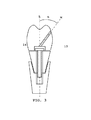
図1は、一つの実施形態による歯科部品キット及び歯科インプラントの概略的な横断面分解図を示す。 FIG. 1 shows a schematic cross-sectional exploded view of a dental component kit and a dental implant according to one embodiment.
歯科部品キットは、インプラントアバットメント2、歯科修復物4、及びねじ3を含む。
The dental part kit includes an
ツーピース設計では、インプラントアバットメント2は、顎骨に固定して接続された歯科インプラント1と歯科修復物4の間の接続を仲介する中間の別個の部分である。従って、インプラントアバットメント2は、インプラント1と物理的に接触し(即ち、歯科インプラント1と当接し)、歯科修復物4のための強固な基礎を形成する。インプラントアバットメント2は、幾つかの小部品からなることができ、様々な設計が考えられ、その詳細については参考文献1に言及されている。従って、本発明は、図面に示された単なる概略図に制限されない。例えば、図面は、アバットメントとインプラントの間に円錐形界面を示すが、界面の側壁は先細である必要はない。さらに、例えばWO97/10769A1又はWO2006/012273A1に開示されるように、様々な形態の回転防止手段が存在しうる。インプラントアバットメント2は、歯科修復物4を固定するための頑丈で信頼性のある基礎を与えるだけでなく、それはまた、それぞれの個人の患者の無数の歯科的必要条件やニーズに答えるために歯科補綴物全体に対するフレキシビリティや適応性を与える。
In the two-piece design, the
歯科修復物4は、完全な歯科補綴物の美観的かつ機能的な部品であり、インプラントアバットメント2によって歯科インプラント1に接続される。後で記載されることに関して、歯科修復物4とインプラントアバットメント2を接続する多数の方法がある。両部品は、一緒に歯科上部構造を形成する。美観的な見地から、歯科修復物4は、例えば色及び形状が自然の歯にできるだけ近くなるように自然の歯に似せるべきである。基本的に、目に見えるとき、歯科修復物4は、自然の歯とは区別がつかないことが想定され、義歯に自然に調和するべきである。唇の歯については、歯科修復物4はまた、エナメルの切縁の半透明性を模倣するべきである。機能的な見地から、歯科修復物4は、患者が不快感や立体的制限なしにかむために歯科補綴物を完全に使用することができるように十分な機械的強度及び耐久性を持つことが必要である。かむ力は、極めて高いものである場合もあり、歯科修復物4は、遭遇される負荷に耐えるように設計される。その最も簡単な形態では、歯科修復物4は、単一の歯の形であることができるが、それに限定されず、さらに歯冠を形成する歯の配列であってもよい。
The dental restoration 4 is an aesthetic and functional part of a complete dental prosthesis and is connected to the
ねじ3は、歯科用途に使用するために好適なねじであり、ねじ頭9及びねじ付きねじ軸10を含む。この及び全ての他の実施形態において、ねじ軸10は、その長さの全部又は一部の上にねじ切りされることができる。ねじ3は、ねじ頭9の直径がねじ軸10の直径より大きいように設計される。この及び全ての他の示された実施形態では、直径は、ねじ軸の軸に対して垂直の方向で円柱形ねじ頭の単一の外側寸法として示される。しかしながら、本発明に関して、用語直径は、円形又は円柱形形状を意味するものとして理解されるべきではない。むしろ、ねじ頭9の外形は、ねじ軸の軸の方向で見ると、丸められたり、多角形にすることができ、又は他のいかなる規則的又は不規則な形状を持つことができる。これは、ねじ山が全くない部分におけるねじ軸の横断面形状にも等しく当てはまる。直径は、ねじ軸の軸を横切る方向のねじの軸又は頭の本体を横切る最も大きな直線的な寸法として理解されるべきである。ねじ頭3はさらに、工具がねじ3全体の回転を実施するためにねじ頭に係合できるように構成される。ねじ3は、インプラントアバットメント2及び歯科修復物4を含む予備組立体15をインプラント1に接続するように構成される。接続は、ねじ軸10が顎骨に固定された歯科インプラント1の対応するねじ山と係合されたねじ山であることによって確立され、それによって予備組立体は、患者の口に固定して位置される。
The
図1に示されているような歯科部品キット及びインプラント1の組み立て状態の概略的な横断面図が図2に示されている。歯科インプラント1は、顎骨に固定して接続される。歯科アバットメント2は、歯科インプラント1とかみ合わされ、例えば歯科インプラント1に部分的に挿入され、それは、インプラントアバットメント2を収容することができるかみ合い部を与えるように構成される。歯科ねじ3は、インプラントアバットメント2に形成された貫通穴5を通して挿入され、ねじ山が歯科インプラント1の対応する部分と係合する。ねじ3を締めることによって、ねじ頭9はねじ座(ここではインプラントアバットメント2の内部表面6によって形成される)に当接し、歯科インプラント1の方に押され、それに固定して接続される。さらに、歯科修復物4は、インプラントアバットメント2に対してそれらの間に形成される界面14によって接続され、その界面は、予備組立体の外部表面に交差する。換言すれば、界面が形成され、そこでは二つの部分が併合され、患者の口に露出される接合部又は継目が存在する。外部表面は、口に対する予備組立体15の外部周囲として理解されるべきであり、即ち、頬及び舌、並びに隣接歯間及び冠状側である。歯科修復物4は、予備組立体15が形成されるときにねじ頭9を収容するように構成された凹所12を含む。歯科修復物4はまた、通路11を含み、それを通って工具が挿入可能である。通路は、ねじ頭9の直径より小さい直径を持つ。通路はさらに、ねじ軸10の直径より大きい直径を持つことができるが、それは必ずしも当てはまらない。通路は、歯科修復物4の外部表面8を凹所12に接続するように構成される。ここで、外部表面8は、患者の口と歯科修復物4のバルク(bulk)の間の境界表面、周辺として理解されるべきである。この特定の実施形態では、通路11の長手方向範囲とねじ軸10の長手方向軸は、軸Lと一致する。それゆえ、通路11の主要な範囲は、ねじ軸10の長手方向軸と整合される。異なる整合もまた、この実施形態の範囲内である。歯科修復物4がインプラントアバットメント2に接続される状態では、ねじ頭9は、インプラントアバットメント2と歯科修復物4の間に位置された凹所又は空間12に包囲される。換言すれば、ねじ9は、これらの二つの部分間に「捕獲」され、予備組立体15から失われることがない拘束ねじになる。従って、凹所12は二つの部分間に形成されることが好ましい。用語「凹所」は、それを作るいかなる特別な方法も要求されないものとして理解されるべきである。それは、単に部屋、空間、又は包囲地である。さらに、その状態では、工具は、通路11を通って通路に沿って挿入され、ねじ頭9と係合し、ねじ3を固定することができる。その状態においても、インプラントアバットメント2と歯科修復物4の間の接続は、インプラントアバットメント2の内部表面6及び歯科修復物4の内部表面7によって確立される。内部表面として、予備組立体15が形成されるとき、通常患者の口に露出されないが予備組立体15によって包囲される表面が考えられる。換言すれば、これらの表面は、予備組立体15の内部表面であり、従って外部表面8とは文字通り反対である。
A schematic cross-sectional view of the assembled assembly of the dental component kit and
インプラントアバットメント2と歯科修復物4の間の界面14は、化学結合、好ましくは接着(gluing)、結合(bonding)及びセメント接着(cementing);熱結合、好ましくはレーザー溶接、摩擦溶接;及び機械結合、好ましくはプレス嵌め、収縮嵌め、ねじ締め及びボルト締めからなる群から選択される少なくとも一つによって形成されるが、これらに限定されない。従って、界面14及びインプラントアバットメント2と歯科修復物4のかみ合い表面は、歯科接着剤もしくはセメントの層、又は隣接材料の熱変性から生じる層を含むことができる。加えて、界面14は、機械的固定手段を含むことができる。
The
歯科部品キットの様々な部品に関して、部品は、ポリマー、好ましくはポリメチルメタクリレート、ポリウレタン、ポリエーテルエーテルケトン;強化ポリマー、好ましくはガラス繊維、炭素繊維及び/又はセラミック粒子によって強化されたポリマー;歯科ハイブリッドセラミック;ガラスセラミック;チタン及びチタン合金;コバルトクロム合金;ジルコニア及びアルミナからなる群から選択される様々な材料を含むことができるが、これらに限定されない。材料の選択は、キットの個々の部品に依存し、さらに患者のニーズ及び必要条件に強く依存し、ケースバイケースでなされなければならない。例えば、一時的な歯科補綴物に対しては、ポリマー及び/又は強化ポリマーが好ましい。長期的な補綴物に対しては、ハイブリッドセラミック、ガラスセラミック、上記金属及び合金又はジルコニア及びアルミナのような酸化セラミックが好ましい。ねじ3に対しては、適切な固定のために十分な機械的強度を保持しながら、ねじをできるだけ小さく保つために高性能鋼又は超高性能材料、例えば非晶質金属が好ましい。従って、材料の選択は、本発明によって考えられる通路及び界面設計から独立している。
With regard to the various parts of the dental part kit, the part is a polymer, preferably polymethyl methacrylate, polyurethane, polyetheretherketone; a reinforced polymer, preferably a polymer reinforced by glass fibers, carbon fibers and / or ceramic particles; a dental hybrid Ceramics; glass ceramics; titanium and titanium alloys; cobalt chromium alloys; various materials selected from the group consisting of zirconia and alumina can be included, but are not limited to these. The choice of material depends on the individual parts of the kit, and also strongly depends on the needs and requirements of the patient and must be made on a case-by-case basis. For example, for temporary dental prostheses, polymers and / or reinforced polymers are preferred. For long-term prostheses, hybrid ceramics, glass ceramics, the above metals and alloys or oxide ceramics such as zirconia and alumina are preferred. For the
歯科部品キットの部品に対する材料の指摘された選択と同様に、これらの部品が形成される好適な方法は、積層造形、好ましくは選択的レーザー溶融、選択的レーザー焼結、電子ビーム溶解、直接金属レーザー焼結、立体リソグラフィー、三次元印刷及び熱溶解積層法;鋳造、成形及び機械加工から選択されることができるが、これらに限定されない。 Similar to the indicated selection of materials for the parts of the dental parts kit, suitable methods for forming these parts are additive manufacturing, preferably selective laser melting, selective laser sintering, electron beam melting, direct metal It can be selected from, but not limited to, laser sintering, stereolithography, three-dimensional printing and hot melt lamination; casting, molding and machining.
上記の歯科部品キットを製造する関連方法は、インプラントアバットメント2と歯科修復物4を整合することによって予備組立体15を形成することを含む。次いで、ねじ3は、インプラントアバットメント2と歯科修復物4の間に位置され、二つの部分は、インプラントアバットメントの内部表面6及び歯科修復物4の内部表面7によって組み立てられ、ねじ頭9は、凹所12に位置され、ねじ軸10の少なくとも一部は、インプラントアバットメントの貫通穴5に収容される。予備組立体15を形成する工程では、インプラントアバットメント2及び歯科修復物4は、それらの中に包囲されるねじ頭9と固定して接続され、インプラントアバットメント2及び歯科修復物4は、化学結合、好ましくは接着、結合及びセメント接着;熱結合、好ましくはレーザー溶接、摩擦溶接;及び機械結合、好ましくはプレス嵌め、収縮嵌め、ねじ締め及びボルト締めからなる群から選択される少なくとも一つの方法によって接続される。少なくとも予備組立体15を形成する工程は、現場外で(ex−situ)、即ち患者の口の外側で実施される。また、予備組立体15を形成することと歯科処置の間に要求される時間的な関係が全くないことが好ましい。従って、組み立ては、患者の実際の処置から完全に独立して実施されることができる。
A related method of manufacturing the above-described dental part kit includes forming a pre-assembly 15 by aligning the
上記の歯科部品キット及びその製造方法は、従来のキット及び方法に対して多数の有意な利点を持つ。 The above-described dental component kit and method of manufacture has a number of significant advantages over conventional kits and methods.
歯科修復物4の通路11は、歯科修復物に従来与えられる通路と比較して有意に狭い。従来の通路は、そこに工具を挿入するだけでなく、歯科ねじ全体がそこを通って挿入され、それがインプラントアバットメントに到達するように形成された。それゆえ、ねじ頭が通り抜けることができるように通路が寸法決定されることが要求された。機械的制限のため、ねじ及びねじ頭は、任意に寸法縮小されることができない。なぜならねじは、耐負荷構成要素であり、補綴物の機能及び信頼性のために不可欠だからである。従って、従来は、通路は、歯科修復物の全体寸法と比較してかなり大きかった。歯科修復物における通路によって生じるかなり大きい不連続性は、その構造的一体性を有意に妨げ、潜在的な機械的弱点であった。また、大きい通路は、歯科修復物の表面上のかなり大きい出口穴を意味した。これらは、美観的な欠点を持ち、従って唇領域のように目に見えるように口の中に位置される修復物の部品に形成されなかった。従って、かかる通路は、出口穴が目に見えにくい領域に出現するように角度を付けられることが要求されることが通常であった。しかしながら、これは、それらがまた歯科医にとって接近することができないという結果をもたらし、それゆえ特別な工具を要求し、歯科処置を複雑にした。美観的な欠点に加えて、大きな出口穴はまた、そこでの高い負荷のために歯の機能表面、例えば咬合面に形成されるべきではなく、それらは頑丈なバルク材料を要求する。上述の問題は、本発明によって軽減される。ねじ3は、ツーピースの予備組立体15の内側に位置され、それは、次いでねじ3がその中に包囲されるように接続される。従って、歯科修復物において通路を通ってねじ全体を挿入する必要がない。通路11は、挿入されるスリムな工具に対して十分な寸法に直径を縮小される。高強度材料から作られた工具は、小さい直径を持ちながら、ねじ3を締め付けるために十分な剛性を持つ。従って、通路11の直径は、絶対最小値に減少されることができる。これは、ずっと小さい出口穴13及び歯科修復物4の増大したバルク材料横断面が増大した機械的強度をもたらすことを意味する。ずっと小さい出口穴13は、これらの穴を歯の目に見える又は機能的な領域から離れて位置することがもはや絶対的に必要でなく、それは、実際には、歯科医にとって最も容易に接近可能である場所に再び位置させることができることを意味する。通路は、従来技術のように角度を付けられたり、もしくは湾曲されたりしてもよく、又は従来技術が避けるべきであった直線的で軸上にしたり、もしくは直線的で軸外にしたりしてもよい。通路は、通路の範囲に沿って変化する又は変化しない横断面を有することができる。
The
歯科部品キットでは、ねじ9は、予備組立体15に包囲され、拘束ねじになる。緩めるねじでのツーピース補綴物の従来の現場組み立ては、通常かなり小さい寸法のねじが失われたり、及び/又は患者が偶然に飲み込んだり、さらに悪いことにそれをのどに詰まらせたりする危険を持つ。また、小さいねじを取り扱うことは、歯科医にとってやっかいでありかつ時間を消費することでありうる。これらの欠点は、歯科ねじが予備組立体15に拘束的に包囲される本発明によって克服される。歯科キットを製造する現場外の方法では、それは、歯科処置の前に十分に組み立てられ、次いで患者の口に移され、小さい歯科ねじをその場で取り扱う際に余分の注意を働かす必要なく歯科インプラントに接続されることができる。これは、処置を有意に簡単にし、患者に対する処置時間及び危険やストレスを減少する。
In the dental part kit, the
また、ツーピース設計の歯科補綴物の現場外組み立ては、例えば接着剤及び歯科セメントのような結合剤を現場で使用して処理することに関連する様々な問題が避けられることを意味する。接合の品質は、患者の口の外側ではずっと効率的に達成されることができ、フレキシビリティが高い。なぜなら様々な他の接合技術は、現場で適用可能でないものを採用しているからである。また、部分間の界面の間隙を確実に閉鎖するために過剰な結合剤を使用しなければならない問題は、本発明の場合のように現場外で組み立てるときに避けられることができる。過剰な結合剤は、流出して除去することが難しく、接近不可能なポケットを形成することさえあり、インプラント全体の欠陥及び炎症を起こしうる。 Also, off-site assembly of two-piece designed dental prostheses means that the various problems associated with using on-site binders such as adhesives and dental cement are avoided. The quality of the joint can be achieved much more efficiently outside the patient's mouth and is highly flexible. This is because various other joining techniques are employed that are not applicable in the field. Also, the problem of having to use excess binder to reliably close the interfacial gap between the parts can be avoided when assembling off-site as in the present invention. Excess binder can be spilled and difficult to remove, can even form inaccessible pockets, and can cause overall implant defects and inflammation.
さらなる技術的な利点は、使用の容易性に関連する:1)修復物における間違ったねじの取り違えがない;2)ねじの拾い上げだけでなく、修復物全体がねじドライバー上のアバットメントを保持する埋め込まれたねじで拾い上げることができるという良好な取り扱いを可能にする。 Further technical advantages relate to ease of use: 1) no wrong screw misplacement in the restoration; 2) not only picking up the screw, but the entire restoration holds the abutment on the screwdriver Enables good handling that can be picked up with an embedded screw.
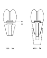
図3は、別の実施形態による歯科部品キット及び歯科インプラントの概略的な横断面図を示す。前の実施形態の特徴と同一の特徴の説明は、省略され、進歩した又は改良された特徴のみがここでは記載されるだろう。 FIG. 3 shows a schematic cross-sectional view of a dental component kit and a dental implant according to another embodiment. Descriptions of features identical to those of the previous embodiments have been omitted, and only advanced or improved features will be described herein.
本実施形態による歯科部品キットはまた、角度を付けられた通路11を有する歯科修復物4を含み、その通路の長手方向範囲(ここでは直線軸M)は、ねじ軸10の長手方向軸と一致する軸Lに対して傾斜されている。これはまた、通路の出口穴13が歯科修復物4の側面に出現することを意味する。好ましくは、LとMの間の角度、即ち通路11の長手方向範囲とねじ軸10の軸の間の角度は、0°〜25°である。
The dental part kit according to this embodiment also includes a dental restoration 4 having an
この実施形態は、時には角度の付いた通路を与えることを要求する患者の個々の必要条件及びニーズに適応されることができるフレキシブルな歯科部品キットを提供する必要性を満足することができる。なぜなら口中へのその設置は、それ以外の方法では、工具で通路に接近することはできないからである。美観が改良されることができ、出口穴13が例えば咬合面に出現するときの歯科修復物4上の高いかむ力の有害な影響がさらに除去されることができる。
This embodiment can satisfy the need to provide a flexible dental parts kit that can be adapted to the individual requirements and needs of patients who sometimes require providing an angled passage. This is because its installation in the mouth cannot be accessed by tools otherwise. The aesthetics can be improved and the detrimental effect of high biting forces on the dental restoration 4 when the
図4A及び4Bは、さらなる実施形態による歯科部品キット及び歯科インプラントと一緒のその歯科部品キットのそれぞれの概略的な横断面分解図を示す。前の実施形態の特徴と同一の特徴の説明は、省略され、進歩した又は改良した特徴のみがここで記載されるだろう。 4A and 4B show a schematic cross-sectional exploded view of a dental component kit and its dental component kit together with a dental implant according to a further embodiment. Descriptions of features identical to those of the previous embodiments have been omitted, and only advanced or improved features will be described here.
上記の実施形態のように、この実施形態は、予備組立体15に凹所12を含む。それはインプラントアバットメント2と歯科修復物4の間に形成される。現在、凹所12は、歯科修復物4の代わりにインプラントアバットメント2に形成される。従って、凹所は、完全にアバットメントに、完全に修復物に、又は、アバットメントと修復物の両方に形成されることができることは明らかであるはずである。通路の方向及び進路は、凹所の形成から独立している。本予備組立体では、ねじ9は再び、インプラントアバットメント2中の凹所12及び周囲の歯科修復物4、例えばその内部表面7によって包囲される。
Like the above embodiment, this embodiment includes a
この実施形態は、歯科部品キットに追加のフレキシビリティと適応性を与える。使用される方法及び材料選択によって、インプラントアバットメント2において凹所12を実現することが好ましく、より容易である。
This embodiment provides additional flexibility and adaptability to the dental part kit. Depending on the method and material selection used, it is preferable and easier to realize the
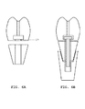
図5A及び5Bは、別の実施形態による歯科部品キット及び歯科インプラントと一緒のその歯科部品キットのそれぞれの概略的な横断面分解図を示す。前の実施形態の特徴と同一の特徴の説明は、省略され、進歩した又は改良した特徴がここで記載されるだろう。 FIGS. 5A and 5B show a schematic cross-sectional exploded view of each of a dental component kit and its dental component kit along with a dental implant according to another embodiment. Descriptions of features identical to those of the previous embodiments have been omitted, and advanced or improved features will now be described.
この実施形態は、組み立て手段の助けでインプラントアバットメント2と歯科修復物4を合併する別の方法を概略的に示す。例えば、インプラントアバットメント2は、突出部16を与えられ、歯科修復物4は、受容断面17を与えられる。予備組立体15では、これらの二つの部品は、互いにかみ合って係合する。図5Aでは、雌雄構成が示され、そこでは突出部は、環状形状を持つことができ、受容断面17は、突出部16を収容し、ぴったり合った適合(ここでは円形凹所)を形成するように構成される。受容断面17は、凹所12の一部として一体的に形成されることができる。しかしながら、可能な構成は、それらに限定されない。また、歯科修復物4が突出部を含み、インプラントアバットメント2がそれに応じて構成された受容断面を含むように、雌雄構成を逆にすることもできる。さらに、突出部16及び/又は受容断面17は、整合及び/又は回転防止特徴(図示せず)を含むことができ、従って予備組立は、明確に区別できる位置のみに制限され、かみ合い工程における動きの自由度は、いったんかみ合ったら整合ミスを避けたり又は個々の部分の整合度を改良するように減少される。再び、通路の方向及び経路は、この実施形態によって開示された他の特徴から独立している。
This embodiment schematically shows another way of merging the
前述したように、本実施形態では、組み立て精度は、組み立て手段が予備組立体15の形成時に自由度を制限するので改良されることができる。また、歯科部品キットの部分を適切に整合するのに費やす時間が短縮される。なぜなら部分は、正しい位置にほとんど自動的に「落ちる」からである。さらに、ぴったり合った適合は、インプラントアバットメント2と歯科修復物4の間の接続の強度を増加し、耐負荷界面14を緩和することができる。結果として、予備組立体15の部分を接続するために使用される結合剤の量を減少することが可能でありうる。
As described above, in this embodiment, the assembly accuracy can be improved because the assembly means limits the degree of freedom when the
図6A及び6Bは、別の実施形態による歯科部品キット、及び歯科インプラントと一緒のその歯科部品キットのそれぞれの概略的な横断面分解図を示す。前の実施形態と同一の特徴の説明は、省略され、進歩した又は改良した特徴のみがここで記載されるだろう。 6A and 6B show schematic cross-sectional exploded views of a dental component kit according to another embodiment and the dental component kit with a dental implant, respectively. The description of the same features as in the previous embodiment has been omitted, and only advanced or improved features will be described here.
この実施形態では、ねじ頭9を包囲する凹所12は、歯科修復物4内に形成される。これは、凹所12が歯科修復物4によって包囲され、歯科修復物4の周囲表面、例えば内部表面7に対して開放する側を持たないことを意味する。歯科修復物4に包囲された凹所12は、ねじ軸10の少なくとも一部を中に収容するように構成された貫通穴18によって歯科修復物4の周囲に接続され、ねじ頭9の直径より小さくかつねじ軸10より大きい直径を持つ。従って、ねじ軸10は、歯科修復物4から部分的に露出されるが、ねじ頭9は、その中に捕獲され、従ってねじ9は拘束ねじになる。貫通穴18によって交差される凹所12の面は、ねじ座として作用する。換言すれば、本実施形態では、歯科修復物4の内側、即ちそのバルク内に空間(凹所12)が形成される。ねじは、それがまだ機能的であるようにバルク中に受け入れられる。機能的とは、ねじが歯科部品キットのための接続/固定手段として操作されかつ使用されることができることを意味する。同時に、ねじは、歯科修復物及びねじの少なくとも一方を破壊せずにバルクから意図せずに抜き出されたりすることができないようにバルク中に収容される。その空間の形状、寸法、および設計は、上記機能性が確保される限り、特に限定されない。
In this embodiment, a
本発明による歯科部品キットはまた、歯科インプラント1、歯科アバットメント2、及び歯科修復物4を調整及び固定するように構成された工具(図示せず)を含むことが好ましい。工具は、歯科用途における上記機能性を達成する限り、いかなる特定の実施形態にも限定されない。一つの例は、ねじ頭9との係合によってねじ3を締めるための単純なねじドライバーである。さらなる例は、Nobel Biocare(登録商標)からのStargrip(商品名)又はUnigrip(商品名)ねじドライバーである。より複雑な工具も使用可能である。
The dental component kit according to the present invention preferably also includes a tool (not shown) configured to adjust and secure the
前述した実施形態のほとんどと一般に組み合わせ可能な別の好ましい実施形態は、歯科部品キットのねじ3が非晶質金属材料及び/又は非晶質金属合金を含むことである。前記非晶質金属材料及び/又は非晶質金属合金はバルク金属ガラスであることがさらに好ましい。さらに、このねじがバルクの非晶質金属材料又は非晶質金属合金からなることが好ましい。従って、本発明の好ましい実施形態は、歯科部品キットにおいて接続/固定手段として使用されるねじ3が少なくとも部分的に、又は任意選択的に完全に非晶質金属材料及び/又は非晶質金属合金、好ましくはバルク金属ガラスであることを規定する。前記材料の限定されない例は、商業的に入手可能な「液体金属(Liquid Metal)」及び他の生体適合性非晶質金属である。
Another preferred embodiment that can generally be combined with most of the previously described embodiments is that the
ねじは、それによって、歯科用途における非晶質金属材料及び合金の特性に従った技術的利益及び利点を取得し、例えば1)有意に高いシステム予備負荷を可能にする超高弾性;2)高い腐食、摩耗、及び引っ掻き抵抗性;3)MRI(磁気共鳴映像法)適合性を改良する低MRI特徴;4)後述するようなネットシェイプ成形の可能性の利点が得られるが、これらに限らない。超機械的特性は、従来金属と比較して減少した耐負荷寸法で高い固定/接続力の伝達を可能にする。歯科ねじに対して非晶質金属を使用することによって、生涯にわたってかむ力に耐え、かむ力の最大に抵抗するために必要と従来思われている最小のねじ寸法が避けられることができる。特に、これは、本実施形態については、ねじ3がその意図した機能を維持しながら一般に寸法を縮小されることができることを意味する。従って、凹所12のサイズを減少することができ、それによって例えば歯科修復物4の中に形成されるなら歯科修復物4の耐負荷材料横断面を増大することができる。また、穴5及び18は、ねじ軸10のサイズを減少するときにサイズを減少することができ、それは、それらが形成される全体の機械的一体性にさらに寄与する。従来の金属と比較すると、ねじの摩擦は減少され、それは、ねじったり又は締めつけたりするトルク、即ちねじを固定する際に使用されるトルクを保持力に変換するのに高い効率性を達成する。別々に考えると、従来の金属におけるねじ接続と同じ耐負荷能力に対しては、低いねじ締めトルクが要求され、それは次にねじを締め付けるときにインプラントに付与されるトルクを低下し、インプラント安定性に効果を与える。
The screw thereby obtains the technical benefits and advantages according to the properties of amorphous metal materials and alloys in dental applications, eg 1) ultra-high elasticity allowing significantly higher system preload; 2) high Corrosion, abrasion, and scratch resistance; 3) Low MRI features that improve MRI compatibility; 4) Benefits of, but not limited to, the possibility of net shape molding as described below . The super-mechanical properties enable high anchoring / connecting force transmission with reduced load bearing dimensions compared to conventional metals. By using an amorphous metal for the dental screw, the smallest thread size conventionally considered necessary to withstand and to resist the maximum biting force can be avoided. In particular, this means that for this embodiment, the
前述の実施形態のほとんどと一般的に組み合わせることができるさらに別の好ましい実施形態は、工具が非晶質金属材料及び/又は非晶質金属合金を含むことである。さらに、非晶質金属材料及び/又は非晶質金属合金がバルク金属ガラスであることがさらに好ましい。さらに、工具が、少なくともねじに係合する部分においてバルクの非晶質金属材料又は非晶質金属合金からなることが好ましい。これは、工具に対しても耐負荷の利点を与え、従ってねじの締め付け時の工具の機械的欠陥が避けられる。従って、本発明の好ましい実施形態は、歯科インプラント、インプラントアバットメント、及び歯科修復物を調整及び固定するように構成された工具が少なくとも部分的に又は任意選択的に完全に非晶質金属材料及び/又は非晶質金属合金、好ましくはバルク金属ガラスから作られることを規定する。前記材料及び実現される技術的利益についての例は、少なくとも前述したものである。特に本実施形態については、これは、工具が、適切な調整及び締め付けを確保するために十分に機能的でありながら有意に寸法縮小されることができることを意味する。同時に、前記工具を受ける歯科部品キットにおける通路11又は開口は、工具の寸法縮小に対して寸法縮小されることができる。通路11の減少した直径は、歯科修復物4の機械的一体性を高める。さらに、美観上の妨げが減少される。なぜなら通路11の出口開口もまた、サイズを縮小され、従ってずっと目に見えにくくなるからである。
Yet another preferred embodiment that can generally be combined with most of the previous embodiments is that the tool comprises an amorphous metal material and / or an amorphous metal alloy. Furthermore, it is more preferable that the amorphous metal material and / or the amorphous metal alloy is a bulk metallic glass. Furthermore, it is preferable that the tool is made of a bulk amorphous metal material or an amorphous metal alloy at least in a portion engaging with the screw. This also provides a load bearing advantage for the tool, thus avoiding mechanical defects in the tool when tightening the screws. Accordingly, a preferred embodiment of the present invention is that a tool configured to condition and secure dental implants, implant abutments, and dental restorations is at least partially or optionally completely amorphous metal material and It is specified that it is made of an amorphous metal alloy, preferably a bulk metallic glass. Examples of said materials and realized technical benefits are at least those mentioned above. Particularly for this embodiment, this means that the tool can be significantly reduced in size while being sufficiently functional to ensure proper adjustment and tightening. At the same time, the
上で示したように、ねじ3及び工具の両方が同時に非晶質金属材料及び/又は非晶質金属合金、好ましくはバルク金属ガラスを含むか又はそれらからなることは、本発明の範囲内である。この組み合わせは、そのとき歯科部品キットをもたらし、ねじ3及び/又は工具、例えば5,11,12及び18を受ける全ての開口のサイズを縮小することができ、従って上述の利点の有利な組み合わせを実現することができる。歯科部品キットにおける開口の最小化はまた、一緒に寸法縮小を可能にする。従って、例えば従来のねじ及び工具を使用するときに機械的に安定するために任せる十分な耐負荷材料を持たない歯科修復物を製造及び適用することが可能でありうる。
As indicated above, it is within the scope of the invention that both the
上記の歯科部品キットを得るための様々な可能な方法がある。 There are various possible ways to obtain the above dental part kit.
第一に、歯科部品キットを製造するための既に記載した方法は、予備組立体を形成する工程の前に追加の工程を含む。この方法では、歯科修復物4は、歯科修復物4の凹所12、貫通穴18、及び通路11が歯科修復物4内に形成されるような追加の製造方法によって製造される。そしてさらに、ねじ3は、前の工程と同時に、好ましくは同じ製造方法で現場で製造される。これは、例えば迅速生産機械でなされることができる。同時製造は、ねじ頭9が凹所12に形成され、ねじ軸10が歯科修復物4の貫通穴18に形成され、ねじ3が歯科修復物4によって包囲される拘束ねじであるように実施される。迅速生産の方法は、複雑な幾何学的形状、例えば従来の成形及び機械加工によって全く得ることができないことが多いアンダーカットを有する部品の製造を可能にする。同じことがここで当てはまる。本実施形態は、複雑な歯形状部品が形成されることを要求し、凹所、貫通穴、通路、及びねじは、その中で高い精度で同時に形成されることになる。迅速生産の使用を通して、包囲されるねじ3での歯科修復物4の組み立ては、ボトムアップアプローチで層ごとに「増大(grown)」されることができる。得られる部分は、ねじを内部に含む正確に造形成された歯科修復物である。増大工程は、増大時にねじ9を保持する支持表面又は突起部の増大を要求しうるが、これらは、例えば増大が完了された後に好適な工具を通路12を通して挿入することによってねじ9が容易に抜け出るようにできるだけ薄く設計される。あるいは、ねじはまた、アセトン又は他の溶媒によって化学的に解放されることができる。
First, the previously described method for manufacturing a dental part kit includes an additional step before the step of forming the pre-assembly. In this method, the dental restoration 4 is manufactured by an additional manufacturing method in which the
第二に、予備組立体を形成する工程の前に、以下の代替工程が考えられる。歯科修復物4の迅速生産増大時に、増大は、凹所12が部分的に(例えば約50%)形成される段階で中断され、ねじ3は、ねじ頭9が部分的に増大された凹所12に位置され、かつねじ軸10が貫通穴18に少なくとも部分的に収容されるように歯科修復物4の内側に位置される。ねじ9をインレイした後、迅速生産法は、インレイしたねじが歯科修復物によって完全に包囲されかつ歯科修復物の増大が完了されるまで継続される。この代替方法では、ねじ3は、歯科修復物4と同時に必ずしも増大される必要はなく、又は迅速生産によって形成された部品でなくてもよい。例えば、もし迅速生産によって同時に増大されることができない、非晶質金属のような超高強度材料のねじ3が要求されるなら、ねじ3は、それにもかかわらず、増大を中断し、まだ完了していない歯科修復物4に最後のねじを挿入することによって歯科修復物4に包囲されることができる。50%増大は、ねじが凹所12及び貫通穴18に挿入されることができる状態についての幾つかの可能な例の一つにすぎない。増大は、凹所12が閉鎖を開始する前、即ち歯科修復物4が凹所12を包囲するのを開始する前に中断されることが必要である。この方法及び前の方法の中で、変更は可能である。歯科修復物は、直立位置で増大されることができる。即ち、増大方向は、インプラントアバットメント2が接続される歯科修復物4の首部の基部から歯科修復物4の冠状側に向かって延びる歯科修復物4の長手方向の略方向である(例えば図2の軸Lに沿う)。あるいは、増大は、長手方向軸に垂直な(即ち、頬、舌、又は隣接歯間の表面の一つから歯科修復物4の対向するものに向かって延びる)横断軸に沿った横たわる位置で行なわれることができる。
Secondly, the following alternative steps are conceivable before the step of forming the pre-assembly. During the rapid production increase of the dental restoration 4, the increase is interrupted when the
第三に、歯科修復物4が分割可能である場合には、凹所12及び貫通穴18に接近可能にするように上記長手方向又は横断方向に沿って分割面が形成されることができる。分割可能な歯科修復物4は、成形、鋳造、及び/又は機械加工のいずれかの好適な方法によって歯科修復物4の二つの部分を製造することによって、又は迅速生産もしくは他の好適な方法を採用して包囲した凹所12、貫通穴18及び通路11を有する歯科修復物4を増大し、それを次いで好適な方法によって適切な分割面に沿って切断してねじが挿入されることができるように少なくとも二つの部分にすることによって先験的に達成されることができる。歯科修復物の部分は、次いで好適な方法によって、好ましくは化学結合、好ましくは接着、結合、及びセメント接着;熱結合、好ましくはレーザー溶接、摩擦溶接、及び機械結合、好ましくはプレス嵌め、収縮嵌め、ねじ締め、及びボルト締めからなる群から選択される少なくとも一つの方法によって再接合され、固定接続されることができる。接合後、ねじ3は包囲され、従って拘束ねじになる。
Thirdly, when the dental restoration 4 can be divided, a dividing surface can be formed along the longitudinal direction or the transverse direction so as to make the
迅速生産の上述の方法は、選択的レーザー溶融、選択的レーザー焼結、電子ビーム溶解、直接金属レーザー焼結、立体リソグラフィー、三次元印刷及び熱溶解積層法からなる群から選択される少なくとも一つであることが好ましい。迅速生産が中断される代替法について、熱溶解積層法が使用されることがより好ましい。なぜなら残っている歯科修復物4がインレイされたねじ3のまわりで最良に増大されることができるからである。
The above-mentioned method of rapid production is at least one selected from the group consisting of selective laser melting, selective laser sintering, electron beam melting, direct metal laser sintering, stereolithography, three-dimensional printing and hot melt lamination. It is preferable that More preferably, hot melt lamination is used for alternative methods where rapid production is interrupted. This is because the remaining dental restoration 4 can best be increased around the
上記実施形態は、ねじ3が歯科修復物4に包囲され、従って損失に対してさらに保証される点で有利である。予備組み立て時に、取り扱いが容易になる。なぜならねじは、別個に取り扱われることが不要であり、歯科修復物4とインプラントアバットメント2のみが合併されることが必要であるからである。また、歯科修復物4及びインプラントアバットメント2は、いったんねじ3が歯科インプラント1と係合したらねじ力によって固定接続される。ねじ3を締め付けるとき、ねじ頭9は、ねじ座に力を付与し、歯科修復物4及びインプラントアバットメント2を一緒に押し、従ってそれらの間の間隙が閉じられる。この脱着可能な圧力嵌め接続は、接着剤又はセメントのような結合剤の使用を要求せず、従ってそれらに関する問題を避けることできる。かくしてワンピース設計の利点が実現される。しかしながら、結合剤は、二つの部分間の接続をさらに確保するために使用されることができるが、必要量は、有意に減少されることができる。
The above embodiment is advantageous in that the
歯科部品キットを製造するためのさらに好ましい方法では、特に、ねじ及び/又は工具が非晶質金属及び/又は非晶質金属合金を含むか又はそれらからなるとき、ねじ及び/又は工具は、ネットシェイプ鋳造(net shape casting)によって形成される。非晶質金属が固化で有意な体積変化を受けないことが非晶質金属の特性である。鋳造された製品は、最終製品に近いので、労力のいる高価な後処理、例えば機械加工及び研磨のような仕上げ処理を避けることができる。それゆえ、本発明は、歯科部品キットの少なくとも特定の構成要素を製造するための特に効率的な方法を提供する。 In a further preferred method for manufacturing a dental part kit, the screw and / or tool is a net, especially when the screw and / or tool comprises or consists of an amorphous metal and / or an amorphous metal alloy. It is formed by shape casting. It is a characteristic of amorphous metals that amorphous metals do not undergo significant volume changes upon solidification. Since the cast product is close to the final product, laborious and expensive post-treatments such as finishing processes such as machining and polishing can be avoided. The present invention therefore provides a particularly efficient method for manufacturing at least certain components of a dental part kit.
最後に、別の実施形態は、顎骨内に埋め込まれるように構成された歯科インプラント1、及び歯科インプラント1、インプラントアバットメント2、及び歯科修復物4を調整及び固定するために構成された工具を含む、前述の実施形態のいずれか一つによる歯科部品キットである。
Finally, another embodiment includes a
Claims (24)
インプラントアバットメント(2)が、内部表面(6)及び外部表面、及び内部にねじ軸の少なくとも一部を収容するように構成された貫通穴(5)を有し、インプラントアバットメントが、顎骨に埋め込まれた歯科インプラント(1)に接続されるように構成され、
歯科修復物(4)が、内部表面(7)及び外部表面(8)、及び工具が挿入可能である通路(11)を有し、歯科修復物が、その内部表面でインプラントアバットメントの内部表面に接続されるように構成され、
ねじ(3)が、ねじ頭(9)及びねじ付きねじ軸(10)を有し、ねじ頭の直径がねじ軸の直径より大きく、
歯科部品キットが、ねじがインプラントアバットメントと歯科修復物の予備組立体(15)を歯科インプラントに接続できるように構成され、
予備組立体が、ねじ頭を包囲する凹所(11)を内部に含むように構成され、それによってねじが拘束ねじであり、
歯科部品キットにおいて、歯科修復物の通路が、歯科修復物の外部表面を凹所に接続し、かつねじのねじ頭の直径より小さい直径を有するか、及び/又は歯科部品キットにおいて、凹所が歯科修復物によって包囲され、かつ歯科修復物の周囲表面に対して開放側を全く持たないように凹所が歯科修復物内に形成される、歯科部品キット。 A dental part kit comprising an implant abutment (2), a dental restoration (4), and a screw (3),
The implant abutment (2) has an inner surface (6) and an outer surface, and a through-hole (5) configured to receive at least a portion of the screw shaft therein, the implant abutment in the jawbone Configured to be connected to an implanted dental implant (1),
A dental restoration (4) has an inner surface (7) and an outer surface (8) and a passage (11) through which a tool can be inserted, the dental restoration being at the inner surface of the inner surface of the implant abutment Configured to be connected to
The screw (3) has a screw head (9) and a threaded screw shaft (10), the diameter of the screw head being larger than the diameter of the screw shaft;
The dental part kit is configured such that the screw can connect the implant abutment and dental restoration pre-assembly (15) to the dental implant;
The pre-assembly is configured to internally include a recess (11) surrounding the screw head, whereby the screw is a captive screw;
In the dental part kit, the path of the dental restoration connects the external surface of the dental restoration to the recess and has a diameter smaller than the diameter of the screw head of the screw and / or in the dental part kit, the recess is A dental part kit, wherein a recess is formed in the dental restoration so as to be surrounded by the dental restoration and to have no open side with respect to the peripheral surface of the dental restoration.
23. A method for manufacturing a dental part kit according to any of claims 18-19, 21-22, wherein the screws and / or tools are formed by net shape casting.
Applications Claiming Priority (3)
| Application Number | Priority Date | Filing Date | Title |
|---|---|---|---|
| GB1317400.8A GB2518849A (en) | 2013-10-01 | 2013-10-01 | Dental Kit-of-parts and Method of assembling the same |
| GB1317400.8 | 2013-10-01 | ||
| PCT/EP2014/070443 WO2015049149A1 (en) | 2013-10-01 | 2014-09-25 | Dental kit-of-parts and method of assembling the same |
Publications (2)
| Publication Number | Publication Date |
|---|---|
| JP2016531643A true JP2016531643A (en) | 2016-10-13 |
| JP2016531643A5 JP2016531643A5 (en) | 2017-10-26 |
Family
ID=49585149
Family Applications (1)
| Application Number | Title | Priority Date | Filing Date |
|---|---|---|---|
| JP2016519835A Pending JP2016531643A (en) | 2013-10-01 | 2014-09-25 | Dental parts kit and assembly method |
Country Status (9)
| Country | Link |
|---|---|
| US (2) | US10111734B2 (en) |
| EP (1) | EP3052047A1 (en) |
| JP (1) | JP2016531643A (en) |
| CN (1) | CN105592819B (en) |
| AU (1) | AU2014331254B2 (en) |
| BR (1) | BR112016007077A2 (en) |
| CA (1) | CA2925925A1 (en) |
| GB (1) | GB2518849A (en) |
| WO (1) | WO2015049149A1 (en) |
Cited By (1)
| Publication number | Priority date | Publication date | Assignee | Title |
|---|---|---|---|---|
| KR101849950B1 (en) * | 2017-12-27 | 2018-04-20 | (주)에스겔 | Dental implant |
Families Citing this family (40)
| Publication number | Priority date | Publication date | Assignee | Title |
|---|---|---|---|---|
| WO2014004704A1 (en) | 2012-06-26 | 2014-01-03 | California Institute Of Technology | Systems and methods for implementing bulk metallic glass-based macroscale gears |
| US20140342179A1 (en) | 2013-04-12 | 2014-11-20 | California Institute Of Technology | Systems and methods for shaping sheet materials that include metallic glass-based materials |
| GB2518849A (en) | 2013-10-01 | 2015-04-08 | Nobel Biocare Services Ag | Dental Kit-of-parts and Method of assembling the same |
| ITMI20132131A1 (en) * | 2013-12-19 | 2015-06-20 | Heraeus Kulzer Gmbh | STRATIFICATION PROCEDURE ABOVE A SHAPED INTERFACE FOR THE IMPROVEMENT OF STRUCTURING TYPES OF SUPERSTRUCTURE FOR PROSTHESIS AND SUPERSTRUCTURE FOR DENTAL PROSTHESIS MADE WITH THIS PROCEDURE |
| CH709687B1 (en) * | 2014-05-23 | 2018-03-29 | Digital Smile Gmbh | Orthodontic apparatus and method for producing an orthodontic appliance. |
| US10639132B2 (en) * | 2014-09-12 | 2020-05-05 | Italo Lozada | Dental prosthesis |
| US10151377B2 (en) | 2015-03-05 | 2018-12-11 | California Institute Of Technology | Systems and methods for implementing tailored metallic glass-based strain wave gears and strain wave gear components |
| US20170056134A1 (en) * | 2015-08-28 | 2017-03-02 | Zimmer, Inc. | Dental abutments and associated systems and methods |
| DE102015116409A1 (en) * | 2015-09-28 | 2017-03-30 | Fraunhofer-Gesellschaft zur Förderung der angewandten Forschung e.V. | Composite body with at least one functional component and a method for producing the composite body |
| EP3970658A1 (en) * | 2015-09-30 | 2022-03-23 | Implant Direct Sybron International LLC | Screw-retained abutment with off-axis feature and method of making same |
| US10968527B2 (en) | 2015-11-12 | 2021-04-06 | California Institute Of Technology | Method for embedding inserts, fasteners and features into metal core truss panels |
| JP6529428B2 (en) * | 2015-12-18 | 2019-06-12 | 株式会社トクヤマデンタル | Adhesive composition for polyaryl ether ketone resin material |
| ES2874799T3 (en) * | 2016-08-31 | 2021-11-05 | Andy Boiangiu | Dental implant cover |
| KR20190119154A (en) | 2017-03-10 | 2019-10-21 | 캘리포니아 인스티튜트 오브 테크놀로지 | Method for manufacturing strain wave gear flexplanes using metal additive manufacturing |
| AT519698B1 (en) * | 2017-03-14 | 2019-04-15 | Lampl Stephan | endodontic |
| WO2018172270A1 (en) * | 2017-03-20 | 2018-09-27 | Straumann Holding Ag | Implant analog |
| US11826224B2 (en) * | 2017-04-03 | 2023-11-28 | Implant Direct Sybron International Llc | Multi-unit dental assembly with off-axis feature |
| EP3630395A4 (en) | 2017-05-24 | 2020-11-25 | California Institute of Technology | Hypoeutectic amorphous metal-based materials for additive manufacturing |
| EP3630392A4 (en) * | 2017-05-26 | 2021-03-03 | California Institute of Technology | Dendrite-reinforced titanium-based metal matrix composites |
| WO2018223117A2 (en) | 2017-06-02 | 2018-12-06 | California Institute Of Technology | High toughness metallic glass-based composites for additive manufacturing |
| US11407034B2 (en) | 2017-07-06 | 2022-08-09 | OmniTek Technology Ltda. | Selective laser melting system and method of using same |
| SE541698C2 (en) * | 2017-11-15 | 2019-11-26 | 3D Tec Sweden Ab | Dental superstructure and method for producing a dental superstructure |
| US11494682B2 (en) | 2017-12-29 | 2022-11-08 | Intel Corporation | Quantum computing assemblies |
| US10847705B2 (en) | 2018-02-15 | 2020-11-24 | Intel Corporation | Reducing crosstalk from flux bias lines in qubit devices |
| US11177912B2 (en) | 2018-03-06 | 2021-11-16 | Intel Corporation | Quantum circuit assemblies with on-chip demultiplexers |
| US11355623B2 (en) | 2018-03-19 | 2022-06-07 | Intel Corporation | Wafer-scale integration of dopant atoms for donor- or acceptor-based spin qubits |
| CN108378937B (en) * | 2018-04-08 | 2020-11-20 | 上海陈信医疗器械有限公司 | Adjustable sleeve crown and mounting method thereof |
| CN108904081A (en) * | 2018-05-29 | 2018-11-30 | 杭州民生立德医疗科技有限公司 | Dentistry implant full dog point socket set rises |
| US11183564B2 (en) | 2018-06-21 | 2021-11-23 | Intel Corporation | Quantum dot devices with strain control |
| US11616126B2 (en) | 2018-09-27 | 2023-03-28 | Intel Corporation | Quantum dot devices with passive barrier elements in a quantum well stack between metal gates |
| ES2730054B2 (en) * | 2019-02-26 | 2021-05-04 | Astradentium Health Tech S L | CASTABLE ADJUSTABLE ABUTMENT FOR THE MANUFACTURE OF A SUPERSTRUCTURE OF A DENTAL PROSTHESIS |
| US11680629B2 (en) | 2019-02-28 | 2023-06-20 | California Institute Of Technology | Low cost wave generators for metal strain wave gears and methods of manufacture thereof |
| US11591906B2 (en) | 2019-03-07 | 2023-02-28 | California Institute Of Technology | Cutting tool with porous regions |
| US11699747B2 (en) | 2019-03-26 | 2023-07-11 | Intel Corporation | Quantum dot devices with multiple layers of gate metal |
| US11682701B2 (en) | 2019-03-27 | 2023-06-20 | Intel Corporation | Quantum dot devices |
| US11387324B1 (en) | 2019-12-12 | 2022-07-12 | Intel Corporation | Connectivity in quantum dot devices |
| US20230100559A1 (en) | 2020-01-07 | 2023-03-30 | The Trustees Of Princeton University | Compositions and Methods for Treatment of Disease by Manipulation of Serine Metabolism |
| US11867216B2 (en) | 2020-06-04 | 2024-01-09 | Hando Kim | Compliant self-anchoring screw with auxetic properties |
| US20220202534A1 (en) * | 2020-12-29 | 2022-06-30 | Mark A. Payne | Distalizer and method of assembly |
| CN113425436B (en) * | 2021-06-22 | 2022-08-09 | 浙江大学医学院附属第一医院 | Method for reducing formation of residual binder in bonding retention implant repair process |
Citations (2)
| Publication number | Priority date | Publication date | Assignee | Title |
|---|---|---|---|---|
| US4854872A (en) * | 1987-09-24 | 1989-08-08 | Detsch Steven G | Prosthetic implant attachment system and method |
| US20020168613A1 (en) * | 2001-05-14 | 2002-11-14 | Riley Robert L. | Near net tooth shaped ceramic crown |
Family Cites Families (19)
| Publication number | Priority date | Publication date | Assignee | Title |
|---|---|---|---|---|
| AU5558099A (en) | 1998-08-12 | 2000-03-06 | Nobel Biocare Ab | One-step threaded implant |
| WO2001050978A1 (en) | 2000-01-14 | 2001-07-19 | Nobel Biocare Ab | Universal implant delivery system |
| NL1030364C2 (en) * | 2005-11-07 | 2007-05-08 | Ft Innovations Fti B V | Implant and method for manufacturing such an implant. |
| DE202007019557U1 (en) | 2006-08-25 | 2013-08-07 | Biomain Ab | Dental superstructure |
| EP2090263A1 (en) | 2008-02-13 | 2009-08-19 | Straumann Holding AG | Abutment with inlay for dental implants |
| JP4783934B2 (en) | 2009-06-10 | 2011-09-28 | 株式会社丸ヱム製作所 | Metal glass fastening screw |
| US20120202170A1 (en) | 2009-10-28 | 2012-08-09 | Johnson Ryan E | Dental implant articles and methods |
| US20120322030A1 (en) | 2010-02-18 | 2012-12-20 | Alpha Bio Tec Ltd. | Modular abutment system for tilted dental implants |
| GB2494099A (en) | 2011-07-06 | 2013-03-06 | Nobel Biocare Services Ag | Dental component with an angled screw channel |
| EP2779936A1 (en) * | 2011-10-04 | 2014-09-24 | Elsner, Edvin | Channel formation for the fixing element of a dental superstructure and method of making the same |
| GB2502328A (en) | 2012-05-24 | 2013-11-27 | Nobel Biocare Services Ag | A dental implant moulded with a through hole |
| GB2502331A (en) | 2012-05-24 | 2013-11-27 | Nobel Biocare Services Ag | A replica for moulding a dental implant with a through hole |
| GB201216214D0 (en) | 2012-09-12 | 2012-10-24 | Nobel Biocare Services Ag | A digital splint |
| EP2922492B1 (en) * | 2012-11-20 | 2021-11-03 | Advanced Implant Intellectual Properties, LLC | Universal aligning adaptor system |
| GB2509138A (en) | 2012-12-21 | 2014-06-25 | Nobel Biocare Services Ag | Dental component with screw fixation |
| GB2509136A (en) | 2012-12-21 | 2014-06-25 | Nobel Biocare Services Ag | Dental component with metal adapter |
| GB2509135A (en) | 2012-12-21 | 2014-06-25 | Nobel Biocare Services Ag | An abutment with conical metal adapter |
| GB2518849A (en) | 2013-10-01 | 2015-04-08 | Nobel Biocare Services Ag | Dental Kit-of-parts and Method of assembling the same |
| US20170202649A1 (en) | 2014-07-25 | 2017-07-20 | Nobel Biocare Services Ag | Provisional prosthetic systems and methods of using same |
-
2013
- 2013-10-01 GB GB1317400.8A patent/GB2518849A/en not_active Withdrawn
-
2014
- 2014-09-25 EP EP14776846.9A patent/EP3052047A1/en not_active Withdrawn
- 2014-09-25 BR BR112016007077A patent/BR112016007077A2/en not_active Application Discontinuation
- 2014-09-25 WO PCT/EP2014/070443 patent/WO2015049149A1/en active Application Filing
- 2014-09-25 CN CN201480054318.6A patent/CN105592819B/en not_active Expired - Fee Related
- 2014-09-25 AU AU2014331254A patent/AU2014331254B2/en not_active Ceased
- 2014-09-25 JP JP2016519835A patent/JP2016531643A/en active Pending
- 2014-09-25 CA CA2925925A patent/CA2925925A1/en not_active Abandoned
- 2014-09-25 US US15/026,559 patent/US10111734B2/en not_active Expired - Fee Related
-
2018
- 2018-10-29 US US16/174,141 patent/US20190125498A1/en not_active Abandoned
Patent Citations (3)
| Publication number | Priority date | Publication date | Assignee | Title |
|---|---|---|---|---|
| US4854872A (en) * | 1987-09-24 | 1989-08-08 | Detsch Steven G | Prosthetic implant attachment system and method |
| US4854872B1 (en) * | 1987-09-24 | 1995-06-27 | Steven G Detsch | Prosthetic implant attachment system and method |
| US20020168613A1 (en) * | 2001-05-14 | 2002-11-14 | Riley Robert L. | Near net tooth shaped ceramic crown |
Cited By (3)
| Publication number | Priority date | Publication date | Assignee | Title |
|---|---|---|---|---|
| KR101849950B1 (en) * | 2017-12-27 | 2018-04-20 | (주)에스겔 | Dental implant |
| WO2019132529A1 (en) * | 2017-12-27 | 2019-07-04 | (주)에스겔 | Dental implant |
| US11529217B2 (en) | 2017-12-27 | 2022-12-20 | Jae-Joon Lee | Dental implant |
Also Published As
| Publication number | Publication date |
|---|---|
| AU2014331254A1 (en) | 2016-05-05 |
| BR112016007077A2 (en) | 2017-08-01 |
| GB201317400D0 (en) | 2013-11-13 |
| US10111734B2 (en) | 2018-10-30 |
| EP3052047A1 (en) | 2016-08-10 |
| AU2014331254B2 (en) | 2018-12-13 |
| US20160242877A1 (en) | 2016-08-25 |
| CN105592819A (en) | 2016-05-18 |
| WO2015049149A1 (en) | 2015-04-09 |
| US20190125498A1 (en) | 2019-05-02 |
| CA2925925A1 (en) | 2015-04-09 |
| GB2518849A (en) | 2015-04-08 |
| CN105592819B (en) | 2019-03-08 |
Similar Documents
| Publication | Publication Date | Title |
|---|---|---|
| JP2016531643A (en) | Dental parts kit and assembly method | |
| JP6860711B2 (en) | Temporary prosthesis system and how to use it | |
| KR101338126B1 (en) | Dental implant | |
| CN103118624B (en) | Implant, base station body | |
| US20170056135A1 (en) | Fixtures for dental implants | |
| JP5694110B2 (en) | Dental implant system | |
| EP2601906B1 (en) | Abutment inlay | |
| JP2012517861A (en) | Components used with implants and associated methods | |
| JP2009527339A (en) | Ceramic / metal dental abutment | |
| KR20070110062A (en) | Dental implant | |
| EP3071141B1 (en) | Dental implant | |
| US9956060B2 (en) | Dental prostheses cemented onto implants and/or abutments having a reverse margin | |
| KR101307411B1 (en) | Dental implant | |
| JP6432911B2 (en) | Single or multi-part implant system having a mounting element with one or more outer annulus | |
| KR101105492B1 (en) | Dental hug bridge assembly and attachment for the same | |
| KR100419738B1 (en) | Dental implant system | |
| HRP20110855A2 (en) | Rotary base adaptable abutment for mechanical connection of dental prothesis with implant | |
| JP2013042775A (en) | Artificial tooth root and artificial tooth root unit |
Legal Events
| Date | Code | Title | Description |
|---|---|---|---|
| A521 | Request for written amendment filed |
Free format text: JAPANESE INTERMEDIATE CODE: A821 Effective date: 20160401 |
|
| A521 | Request for written amendment filed |
Free format text: JAPANESE INTERMEDIATE CODE: A523 Effective date: 20170915 |
|
| A621 | Written request for application examination |
Free format text: JAPANESE INTERMEDIATE CODE: A621 Effective date: 20170915 |
|
| A977 | Report on retrieval |
Free format text: JAPANESE INTERMEDIATE CODE: A971007 Effective date: 20180711 |
|
| A131 | Notification of reasons for refusal |
Free format text: JAPANESE INTERMEDIATE CODE: A131 Effective date: 20180807 |
|
| A521 | Request for written amendment filed |
Free format text: JAPANESE INTERMEDIATE CODE: A523 Effective date: 20181031 |
|
| A02 | Decision of refusal |
Free format text: JAPANESE INTERMEDIATE CODE: A02 Effective date: 20190219 |
|
| A521 | Request for written amendment filed |
Free format text: JAPANESE INTERMEDIATE CODE: A821 Effective date: 20190607 Free format text: JAPANESE INTERMEDIATE CODE: A523 Effective date: 20190607 |
|
| C60 | Trial request (containing other claim documents, opposition documents) |
Free format text: JAPANESE INTERMEDIATE CODE: C60 Effective date: 20190607 |
|
| A911 | Transfer to examiner for re-examination before appeal (zenchi) |
Free format text: JAPANESE INTERMEDIATE CODE: A911 Effective date: 20190617 |
|
| C21 | Notice of transfer of a case for reconsideration by examiners before appeal proceedings |
Free format text: JAPANESE INTERMEDIATE CODE: C21 Effective date: 20190618 |
|
| A912 | Re-examination (zenchi) completed and case transferred to appeal board |
Free format text: JAPANESE INTERMEDIATE CODE: A912 Effective date: 20190719 |
|
| C211 | Notice of termination of reconsideration by examiners before appeal proceedings |
Free format text: JAPANESE INTERMEDIATE CODE: C211 Effective date: 20190723 |
|
| C22 | Notice of designation (change) of administrative judge |
Free format text: JAPANESE INTERMEDIATE CODE: C22 Effective date: 20200317 |
|
| C22 | Notice of designation (change) of administrative judge |
Free format text: JAPANESE INTERMEDIATE CODE: C22 Effective date: 20200522 |
|
| C13 | Notice of reasons for refusal |
Free format text: JAPANESE INTERMEDIATE CODE: C13 Effective date: 20200529 |
|
| C23 | Notice of termination of proceedings |
Free format text: JAPANESE INTERMEDIATE CODE: C23 Effective date: 20201110 |
|
| C03 | Trial/appeal decision taken |
Free format text: JAPANESE INTERMEDIATE CODE: C03 Effective date: 20201211 |
|
| C30A | Notification sent |
Free format text: JAPANESE INTERMEDIATE CODE: C3012 Effective date: 20201211 |