JP2016527043A - Method and system for medical imaging and information display - Google Patents
Method and system for medical imaging and information display Download PDFInfo
- Publication number
- JP2016527043A JP2016527043A JP2016532702A JP2016532702A JP2016527043A JP 2016527043 A JP2016527043 A JP 2016527043A JP 2016532702 A JP2016532702 A JP 2016532702A JP 2016532702 A JP2016532702 A JP 2016532702A JP 2016527043 A JP2016527043 A JP 2016527043A
- Authority
- JP
- Japan
- Prior art keywords
- imaging
- point
- modes
- image
- different
- Prior art date
- Legal status (The legal status is an assumption and is not a legal conclusion. Google has not performed a legal analysis and makes no representation as to the accuracy of the status listed.)
- Pending
Links
Images
Classifications
-
- A—HUMAN NECESSITIES
- A61—MEDICAL OR VETERINARY SCIENCE; HYGIENE
- A61B—DIAGNOSIS; SURGERY; IDENTIFICATION
- A61B8/00—Diagnosis using ultrasonic, sonic or infrasonic waves
- A61B8/52—Devices using data or image processing specially adapted for diagnosis using ultrasonic, sonic or infrasonic waves
- A61B8/5207—Devices using data or image processing specially adapted for diagnosis using ultrasonic, sonic or infrasonic waves involving processing of raw data to produce diagnostic data, e.g. for generating an image
-
- A—HUMAN NECESSITIES
- A61—MEDICAL OR VETERINARY SCIENCE; HYGIENE
- A61B—DIAGNOSIS; SURGERY; IDENTIFICATION
- A61B8/00—Diagnosis using ultrasonic, sonic or infrasonic waves
- A61B8/46—Ultrasonic, sonic or infrasonic diagnostic devices with special arrangements for interfacing with the operator or the patient
- A61B8/461—Displaying means of special interest
-
- A—HUMAN NECESSITIES
- A61—MEDICAL OR VETERINARY SCIENCE; HYGIENE
- A61B—DIAGNOSIS; SURGERY; IDENTIFICATION
- A61B8/00—Diagnosis using ultrasonic, sonic or infrasonic waves
- A61B8/46—Ultrasonic, sonic or infrasonic diagnostic devices with special arrangements for interfacing with the operator or the patient
- A61B8/467—Ultrasonic, sonic or infrasonic diagnostic devices with special arrangements for interfacing with the operator or the patient characterised by special input means
- A61B8/469—Ultrasonic, sonic or infrasonic diagnostic devices with special arrangements for interfacing with the operator or the patient characterised by special input means for selection of a region of interest
-
- A—HUMAN NECESSITIES
- A61—MEDICAL OR VETERINARY SCIENCE; HYGIENE
- A61B—DIAGNOSIS; SURGERY; IDENTIFICATION
- A61B8/00—Diagnosis using ultrasonic, sonic or infrasonic waves
- A61B8/52—Devices using data or image processing specially adapted for diagnosis using ultrasonic, sonic or infrasonic waves
- A61B8/5215—Devices using data or image processing specially adapted for diagnosis using ultrasonic, sonic or infrasonic waves involving processing of medical diagnostic data
- A61B8/5238—Devices using data or image processing specially adapted for diagnosis using ultrasonic, sonic or infrasonic waves involving processing of medical diagnostic data for combining image data of patient, e.g. merging several images from different acquisition modes into one image
- A61B8/5246—Devices using data or image processing specially adapted for diagnosis using ultrasonic, sonic or infrasonic waves involving processing of medical diagnostic data for combining image data of patient, e.g. merging several images from different acquisition modes into one image combining images from the same or different imaging techniques, e.g. color Doppler and B-mode
-
- G—PHYSICS
- G16—INFORMATION AND COMMUNICATION TECHNOLOGY [ICT] SPECIALLY ADAPTED FOR SPECIFIC APPLICATION FIELDS
- G16H—HEALTHCARE INFORMATICS, i.e. INFORMATION AND COMMUNICATION TECHNOLOGY [ICT] SPECIALLY ADAPTED FOR THE HANDLING OR PROCESSING OF MEDICAL OR HEALTHCARE DATA
- G16H30/00—ICT specially adapted for the handling or processing of medical images
- G16H30/20—ICT specially adapted for the handling or processing of medical images for handling medical images, e.g. DICOM, HL7 or PACS
-
- G—PHYSICS
- G16—INFORMATION AND COMMUNICATION TECHNOLOGY [ICT] SPECIALLY ADAPTED FOR SPECIFIC APPLICATION FIELDS
- G16H—HEALTHCARE INFORMATICS, i.e. INFORMATION AND COMMUNICATION TECHNOLOGY [ICT] SPECIALLY ADAPTED FOR THE HANDLING OR PROCESSING OF MEDICAL OR HEALTHCARE DATA
- G16H30/00—ICT specially adapted for the handling or processing of medical images
- G16H30/40—ICT specially adapted for the handling or processing of medical images for processing medical images, e.g. editing
-
- G—PHYSICS
- G16—INFORMATION AND COMMUNICATION TECHNOLOGY [ICT] SPECIALLY ADAPTED FOR SPECIFIC APPLICATION FIELDS
- G16H—HEALTHCARE INFORMATICS, i.e. INFORMATION AND COMMUNICATION TECHNOLOGY [ICT] SPECIALLY ADAPTED FOR THE HANDLING OR PROCESSING OF MEDICAL OR HEALTHCARE DATA
- G16H50/00—ICT specially adapted for medical diagnosis, medical simulation or medical data mining; ICT specially adapted for detecting, monitoring or modelling epidemics or pandemics
- G16H50/20—ICT specially adapted for medical diagnosis, medical simulation or medical data mining; ICT specially adapted for detecting, monitoring or modelling epidemics or pandemics for computer-aided diagnosis, e.g. based on medical expert systems
-
- G—PHYSICS
- G16—INFORMATION AND COMMUNICATION TECHNOLOGY [ICT] SPECIALLY ADAPTED FOR SPECIFIC APPLICATION FIELDS
- G16Z—INFORMATION AND COMMUNICATION TECHNOLOGY [ICT] SPECIALLY ADAPTED FOR SPECIFIC APPLICATION FIELDS, NOT OTHERWISE PROVIDED FOR
- G16Z99/00—Subject matter not provided for in other main groups of this subclass
-
- A—HUMAN NECESSITIES
- A61—MEDICAL OR VETERINARY SCIENCE; HYGIENE
- A61B—DIAGNOSIS; SURGERY; IDENTIFICATION
- A61B8/00—Diagnosis using ultrasonic, sonic or infrasonic waves
- A61B8/08—Detecting organic movements or changes, e.g. tumours, cysts, swellings
-
- A—HUMAN NECESSITIES
- A61—MEDICAL OR VETERINARY SCIENCE; HYGIENE
- A61B—DIAGNOSIS; SURGERY; IDENTIFICATION
- A61B8/00—Diagnosis using ultrasonic, sonic or infrasonic waves
- A61B8/46—Ultrasonic, sonic or infrasonic diagnostic devices with special arrangements for interfacing with the operator or the patient
- A61B8/461—Displaying means of special interest
- A61B8/466—Displaying means of special interest adapted to display 3D data
-
- A—HUMAN NECESSITIES
- A61—MEDICAL OR VETERINARY SCIENCE; HYGIENE
- A61B—DIAGNOSIS; SURGERY; IDENTIFICATION
- A61B8/00—Diagnosis using ultrasonic, sonic or infrasonic waves
- A61B8/46—Ultrasonic, sonic or infrasonic diagnostic devices with special arrangements for interfacing with the operator or the patient
- A61B8/467—Ultrasonic, sonic or infrasonic diagnostic devices with special arrangements for interfacing with the operator or the patient characterised by special input means
-
- A—HUMAN NECESSITIES
- A61—MEDICAL OR VETERINARY SCIENCE; HYGIENE
- A61B—DIAGNOSIS; SURGERY; IDENTIFICATION
- A61B8/00—Diagnosis using ultrasonic, sonic or infrasonic waves
- A61B8/48—Diagnostic techniques
- A61B8/483—Diagnostic techniques involving the acquisition of a 3D volume of data
-
- A—HUMAN NECESSITIES
- A61—MEDICAL OR VETERINARY SCIENCE; HYGIENE
- A61B—DIAGNOSIS; SURGERY; IDENTIFICATION
- A61B8/00—Diagnosis using ultrasonic, sonic or infrasonic waves
- A61B8/48—Diagnostic techniques
- A61B8/485—Diagnostic techniques involving measuring strain or elastic properties
-
- A—HUMAN NECESSITIES
- A61—MEDICAL OR VETERINARY SCIENCE; HYGIENE
- A61B—DIAGNOSIS; SURGERY; IDENTIFICATION
- A61B8/00—Diagnosis using ultrasonic, sonic or infrasonic waves
- A61B8/48—Diagnostic techniques
- A61B8/486—Diagnostic techniques involving arbitrary m-mode
-
- A—HUMAN NECESSITIES
- A61—MEDICAL OR VETERINARY SCIENCE; HYGIENE
- A61B—DIAGNOSIS; SURGERY; IDENTIFICATION
- A61B8/00—Diagnosis using ultrasonic, sonic or infrasonic waves
- A61B8/48—Diagnostic techniques
- A61B8/488—Diagnostic techniques involving Doppler signals
-
- A—HUMAN NECESSITIES
- A61—MEDICAL OR VETERINARY SCIENCE; HYGIENE
- A61B—DIAGNOSIS; SURGERY; IDENTIFICATION
- A61B8/00—Diagnosis using ultrasonic, sonic or infrasonic waves
- A61B8/52—Devices using data or image processing specially adapted for diagnosis using ultrasonic, sonic or infrasonic waves
- A61B8/5292—Devices using data or image processing specially adapted for diagnosis using ultrasonic, sonic or infrasonic waves using additional data, e.g. patient information, image labeling, acquisition parameters
Abstract
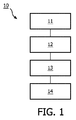
本発明は医療イメージング及び情報表示のための方法とシステムを提供する。本発明の一態様によれば、以下のステップを有する医療イメージング及び情報表示の方法10が提案される:医療イメージング装置の複数の異なるイメージングモードの各モードにおいて対象のイメージング面若しくはイメージングボリュームにおける複数の点の各点のイメージングデータを取得するステップ11;上記各モードにおける点のイメージングデータ及び上記各モードにおける点に隣接する上記複数の点のうち少なくとも一つの他の点のイメージングデータを既定モデルに適用することによって、上記各点について値を導出するステップ12、既定モデルは対象に関する臨床医療アプリケーションに従って選択される;導出された値全てに基づいて画像を構成するステップ13;及び構成された画像をユーザに表示するステップ14。従って、医療イメージング及び情報表示の新規の方法は医師の負担を軽減し、従来のROI法と比較して高解像度で画像を医師に提供し得る。The present invention provides methods and systems for medical imaging and information display. According to one aspect of the present invention, a medical imaging and information display method 10 is proposed having the following steps: a plurality of imaging planes or imaging volumes of a subject in each of a plurality of different imaging modes of a medical imaging device. Acquiring imaging data of each point of the step 11; applying imaging data of the point in each mode and imaging data of at least one other point among the plurality of points adjacent to the point in each mode to the default model By deriving a value for each of the points 12, a default model is selected according to the clinical medical application for the subject; constructing an image 13 based on all the derived values; Steps to display 4. Therefore, the new method of medical imaging and information display can reduce the burden on the doctor and can provide the doctor with an image at a higher resolution than the conventional ROI method.
Description
本発明は臨床医療イメージングに、より具体的には医療イメージング及び情報表示のための方法とシステムに関する。 The present invention relates to clinical medical imaging, and more particularly to methods and systems for medical imaging and information display.
今日、臨床医療イメージングは患者について必要な情報を医師に提供する重要な役割を担っている。例えば、CT、MRI、超音波若しくは同様のものなど、様々なイメージングモダリティがこれに関して医師を支援するために現在利用可能である。各イメージングモダリティごとに、異なるイメージングモードがある。 Today, clinical medical imaging plays an important role in providing doctors with the information they need about their patients. Various imaging modalities are currently available to assist physicians in this regard, such as CT, MRI, ultrasound or the like. There are different imaging modes for each imaging modality.
超音波を例にとると、超音波イメージングは無放射で、非侵襲的で、リアルタイムの低コスト技術であるため、臨床用途において広く利用されている。当該技術分野で周知の通り、超音波イメージングにおいては異なる種類のモードがあり、例えばBモード超音波、カラー超音波、コントラスト超音波、ストレイン超音波及び定量エラストグラフィ超音波を含むエラストグラフィ超音波があるがこれらに限定されない。 Taking ultrasound as an example, ultrasound imaging is widely used in clinical applications because it is a non-radiative, non-invasive, real-time, low-cost technology. As is well known in the art, there are different types of modes in ultrasound imaging, e.g. elastographic ultrasound including B-mode ultrasound, color ultrasound, contrast ultrasound, strain ultrasound and quantitative elastography ultrasound. There is, but is not limited to these.
患者について包括的な情報を得るために、医師はしばしば異なるイメージングモードからのイメージングデータを組み合わせる必要がある。全イメージングデータを最適に使用する方法は人間にとって困難な問題である。その主な理由は臨床オブジェクトが高次元空間に存在し、人間の知覚が限られており、高次元問題を解く能力に欠けていることである。 In order to obtain comprehensive information about a patient, physicians often need to combine imaging data from different imaging modes. How to optimally use all imaging data is a difficult problem for humans. The main reason is that clinical objects exist in a high dimensional space, human perception is limited, and the ability to solve high dimensional problems is lacking.
機械学習などのコンピュータ技術は人間よりも高次元問題を扱う能力に優れている。従って、コンピュータ技術に基づく臨床判断支援(CDS)システムはそうした包括的情報を医師に提供するのに重要な役割を担う。 Computer technology such as machine learning is more capable of handling higher dimensional problems than humans. Therefore, computer-based clinical decision support (CDS) systems play an important role in providing such comprehensive information to physicians.
しかしながら、臨床オブジェクトについて、医師は最初に患者のイメージング面若しくはイメージングボリュームにおいてオブジェクトを示すために関心領域(ROI)を選択し、そして構造的情報、機能的情報若しくは診断情報自体をも提供するために関連分析若しくはコンピュータアルゴリズムを適用することを要求される。 However, for clinical objects, the physician first selects a region of interest (ROI) to represent the object on the patient's imaging surface or volume and also provides structural, functional, or diagnostic information itself. It is required to apply association analysis or computer algorithm.
US6186949B1は符号化送受信(coded excitation)を用いる三次元血流イメージングのための方法と装置を開示する。符号化送受信と血管壁フィルタリング(wall filtering)を用いて三次元血流イメージングを実行する際、広帯域パルスの符号化シーケンス(基本周波数を中心とする)が特定送信焦点位置へ複数回送信される。受信時、各送信ごとに取得される受信信号は圧縮されてバンドパスフィルタリングされ、基本周波数を中心とする圧縮パルスを分離する。そして圧縮され分離された信号は血流イメージングデータを抽出するために血管壁フィルタリングされる。このプロセスは血流イメージングデータのボリュームを取得するために多数のスキャン面の各々において多数の送信焦点位置について繰り返される。そしてボリュームレンダリングされた画像が生成され、これはユーザが任意の角度からデータボリュームを見ることを可能にする。加えて、データボリュームはデータボリュームを通る任意切断面の二次元画像を生成するように再フォーマットされ得る。 US6186949B1 discloses a method and apparatus for three-dimensional blood flow imaging using coded transmission. When performing three-dimensional blood flow imaging using coded transmission / reception and vessel wall filtering, a coded sequence of broadband pulses (centered on the fundamental frequency) is transmitted multiple times to a specific transmission focal position. During reception, the received signal acquired for each transmission is compressed and bandpass filtered to separate compressed pulses centered on the fundamental frequency. The compressed and separated signal is then subjected to vessel wall filtering to extract blood flow imaging data. This process is repeated for multiple transmit focal positions in each of multiple scan planes to obtain a volume of blood flow imaging data. A volume rendered image is then generated, which allows the user to view the data volume from any angle. In addition, the data volume can be reformatted to produce a two-dimensional image of any cut plane through the data volume.
本発明の発明者らは上記のようなROIの手動選択に基づくCDSシステムが複数の欠点を持つことを認識した。 The inventors of the present invention have recognized that a CDS system based on manual selection of ROI as described above has several drawbacks.
第一に、ROI選択プロセスは異なるモードで個別に実行され、医師は同じオブジェクトを示そうとするために異なるモードについてROIを選択する必要がある。これはリアルタイムに実行されることができず、スクリーニングプロセスの最中にCDS情報を提供することは不可能である。さらに、この選択プロセスはミスにつながることがあり、時間がかかる。時に医師は、特に若手の医師は、正しいROIを選択するのが難しく、従って検査若しくは診断されるべきオブジェクトを見過ごす。加えて、例えばROI全体に対して一つの値など、CDS情報はROIごとに提供される。言い換えればCDS情報の粒度は低い。加えて、医師は一つの局所ROIについて異なるモードからの情報を提供されるので、臨床オブジェクトの全面的理解を得ることが難しい。 First, the ROI selection process is performed separately in different modes, and the physician needs to select ROIs for different modes in order to try to show the same object. This cannot be performed in real time and it is impossible to provide CDS information during the screening process. Furthermore, this selection process can lead to mistakes and is time consuming. Sometimes doctors, especially young doctors, have difficulty selecting the correct ROI and thus overlook the object to be examined or diagnosed. In addition, CDS information is provided for each ROI, such as one value for the entire ROI. In other words, the granularity of CDS information is low. In addition, since the physician is provided with information from different modes for one local ROI, it is difficult to obtain a full understanding of clinical objects.
第二に、異なるイメージングモードからの画像データは一般に異なるモード間を切り替えることによって連続的に取得され、送信される無線周波数信号は一般に異なるイメージングモードによって異なる。送信された無線周波数信号が異なるとき、取得画像中のピクセルの数と位置も異なる。加えて、異なるモードにおけるイメージング面若しくはイメージングボリュームはイメージング装置と患者間の相対位置における変化に起因して異なる可能性がある。例えば、超音波スクリーニング中、医師によって保持される超音波プローブの位置及び/又は角度は、医師が異なるモード間を切り替えるときに超音波プローブの視野も変更されるように変更され得る。従って、異なるイメージングモードの画像データはピクセルレベルの対応を持たない。結果として、異なるモードの画像データのピクセルレベルの組み合わせは非常に複雑になる。 Secondly, image data from different imaging modes is generally acquired continuously by switching between different modes, and the transmitted radio frequency signal is typically different for different imaging modes. When the transmitted radio frequency signals are different, the number and location of the pixels in the acquired image are also different. In addition, the imaging surface or imaging volume in the different modes can be different due to changes in the relative position between the imaging device and the patient. For example, during ultrasound screening, the position and / or angle of the ultrasound probe held by the physician can be changed so that when the physician switches between different modes, the field of view of the ultrasound probe is also altered. Accordingly, image data in different imaging modes has no pixel level correspondence. As a result, the pixel level combination of different modes of image data becomes very complex.
特殊な場合として、あるイメージングモードについては、ピクセルレベルの対応を伴う異なるモードの同時イメージングが実現されるとみなされ得る。例えば、カラーモードのために使用される無線周波数(RF)信号シーケンスはBモードイメージングモードのために使用されるものと同じである。これに基づき、カラー及びBモード間のピクセルレベルの対応が得られ、これら二つのモードからの画像データのピクセルレベルの組み合わせが実現されることができる。しかしながら、今日これら二つのモードの組み合わせはイメージングデータのピクセルワイズの重畳に過ぎない。つまり、各ピクセルについて組み合わされたイメージングデータは二つのモードにおけるそのピクセルのイメージングデータの総和である。従って、組み合わされたイメージングデータはいかなる追加CDS情報も提供しない。医師はそれらを従来のイメージングモードとして使用し、それらを従来の方法で処理しなければならない。従って、満足のいくやり方で高次元データを同時に処理する方法は依然医師にとって困難な課題のままである。一方、こうした種類の現在のイメージングモードのRF信号は異なるイメージングモードを生成するには制限が多過ぎることが多い。その数は一般に2を超えず、これは十分なイメージング情報を提供してその後のCDS処理ステップを実現するためには不十分であり得る。 As a special case, for certain imaging modes, different modes of simultaneous imaging with pixel level correspondence can be considered to be realized. For example, the radio frequency (RF) signal sequence used for the color mode is the same as that used for the B-mode imaging mode. Based on this, a pixel level correspondence between the color and B modes is obtained, and a combination of pixel levels of image data from these two modes can be realized. However, today the combination of these two modes is only a pixel-wise superposition of imaging data. That is, the combined imaging data for each pixel is the sum of the imaging data for that pixel in the two modes. Thus, the combined imaging data does not provide any additional CDS information. The physician must use them as conventional imaging modes and process them in the conventional manner. Thus, the method of simultaneously processing high-dimensional data in a satisfactory manner remains a difficult task for physicians. On the other hand, these types of current imaging mode RF signals are often too restrictive to produce different imaging modes. That number generally does not exceed 2, which may be insufficient to provide sufficient imaging information to implement subsequent CDS processing steps.
従って、医師が異なるモードのイメージングデータからROIを選択することを課せられることなく、異なるイメージングモードから包括的情報を医師に提供するために、医療イメージング及び情報表示のための新規の方法とシステムを提供することが有利であり得る。上述の従来技術と比較して、異なるイメージングモードは特定モードに限定されず、その数は必要であれば可能な限り多くなり得る。 Accordingly, a novel method and system for medical imaging and information display to provide a physician with comprehensive information from different imaging modes without being imposed on the physician to select an ROI from different modes of imaging data. It may be advantageous to provide. Compared to the prior art described above, the different imaging modes are not limited to specific modes, and the number can be as high as possible if necessary.
本発明の一態様によれば、以下のステップを有する医療イメージングと情報表示の方法が提案される:医療イメージング装置の複数の異なるイメージングモードの各モードにおいて対象のイメージング面若しくはイメージングボリュームにおける複数の点の各点のイメージングデータを取得するステップ;当該各点について、当該各モードにおける点のイメージングデータと、当該各モードにおける点に隣接する当該複数の点のうち少なくとも一つの他の点のイメージングデータとを既定モデルに適用することによって、値を導出するステップ、既定モデルは対象に関する臨床医療アプリケーションに従って選択される;導出された値全てに基づいて画像を構成するステップ;及び構成された画像をユーザに表示するステップ。 According to one aspect of the present invention, a method of medical imaging and information display is proposed having the following steps: a plurality of points on the imaging plane or imaging volume of the object in each of a plurality of different imaging modes of the medical imaging device. Obtaining imaging data of each point of the above; for each point, imaging data of the point in each mode and imaging data of at least one other point among the plurality of points adjacent to the point in each mode; Deriving a value by applying to the default model; the default model is selected according to a clinical medical application for the subject; constructing an image based on all the derived values; and Step to display.
従来の画像処理法と比較して、本発明にかかる方法は医師が異なるモードにおいてオブジェクトを示すために関心領域(ROI)を選択し、そして情報自体を提供するために関連分析若しくはコンピュータアルゴリズムを適用することを要求しないので、本発明にかかる方法は医師の負担を大幅に軽減する。 Compared to conventional image processing methods, the method according to the present invention allows a physician to select a region of interest (ROI) to show an object in different modes and apply a relational analysis or computer algorithm to provide the information itself The method according to the present invention greatly reduces the burden on the doctor.
さらに、本発明にかかる方法では、点のイメージングデータと、点に隣接する少なくとも一つの他の点のイメージングデータとを既定医療アプリケーション関連モデルに適用することによって、イメージング面若しくはイメージングボリュームにおける各点について値が導出され、そして導出された値全てに基づいて画像が構成されてユーザに表示されるので、方法は医師にとってリアルタイムスクリーニングを可能にする。例えば、超音波スクリーニング中、医師がプローブを特定面へ動かすとき、視野内の各ピクセルについての導出値は画像として鮮明に表示され、医師にリアルタイムに提示され、医師がプローブの角度若しくは位置を変更するときは、提示された画像がそれに従って更新される。さらに、これは臨床オブジェクトについての情報をピクセルレベルで直接伝える画像を提示することができるので、医師は従来のROI法と比較して高解像度画像を提供され、臨床オブジェクトの全面的理解を得ることができる。従って、医師はオブジェクトを見過ごすことがない。 Furthermore, in the method according to the present invention, for each point in the imaging plane or imaging volume, the imaging data of the point and the imaging data of at least one other point adjacent to the point are applied to the predefined medical application related model. Since the values are derived and an image is constructed and displayed to the user based on all of the derived values, the method allows real-time screening for the physician. For example, during ultrasound screening, when the doctor moves the probe to a specific plane, the derived values for each pixel in the field of view are clearly displayed as an image and presented to the doctor in real time, and the doctor changes the angle or position of the probe When doing so, the presented image is updated accordingly. In addition, it can present images that directly convey information about clinical objects at the pixel level, so physicians are provided with high resolution images compared to conventional ROI methods to gain a full understanding of clinical objects Can do. Therefore, the doctor does not overlook the object.
一方、イメージング面若しくはイメージングボリュームにおける各点についての値は点自体のイメージングデータのみからではなく、点に隣接する少なくとも一つの他の点のイメージングデータにも基づいて導出される。このように、本方法を使用することはさらに導出値の品質を改良し、及び/又は導出値がより多くの臨床情報を提供することを可能にし、より良好で多くの情報を含む構成画像をもたらし得る。言い換えれば、出力画像は医師にとってより有用で信頼できるものとなる。 On the other hand, the value for each point on the imaging surface or imaging volume is derived not only from the imaging data of the point itself, but also based on the imaging data of at least one other point adjacent to the point. Thus, using this method can further improve the quality of the derived value and / or allow the derived value to provide more clinical information, better constructing a constituent image that contains more information. Can bring. In other words, the output image is more useful and reliable for the doctor.
ここで、当業者は少なくとも一つの他の点の各々と点との間の距離が既定値を超えないことを容易に理解し得る。例えば、一実施例において、少なくとも一つの他の点は目標点に最も近い点であり得る。言い換えれば、それらはイメージング面若しくはイメージングボリュームにおいて目標点に関して右上、左上、右下、左下の点であり得る。 Here, one of ordinary skill in the art can readily appreciate that the distance between each of the at least one other point and the point does not exceed a predetermined value. For example, in one embodiment, at least one other point can be the point closest to the target point. In other words, they can be the upper right, upper left, lower right, lower left points with respect to the target point in the imaging plane or imaging volume.
既定モデルは臨床医療アプリケーションに関する臨床情報を提供する臨床医療アプリケーションに関する任意のモデルであり得る。 The default model can be any model for a clinical medical application that provides clinical information about the clinical medical application.
典型的に、既定モデルは非線形である。一実施例において、既定モデルは機械学習ベースモデルである。別の実施例では、構成画像が臨床判断支援情報を医師に提供し得るよう、既定モデルは臨床判断支援(CDS)モデルであり得る。CDSモデルについて、CDSモデルは患者などの対象に関する診断情報を出力するモデルであり得ることが当業者によって理解される。しかしながら、CDSモデルはそれに限定されず、一部の種類のCDSモデルは医師が導出値若しくは構成画像に基づいて対象の診断結果若しくは健康状態を取得することができないようなものである。言い換えれば、CDSモデルの出力値は対象に関する構造的若しくは機能的情報であり得、医師は構造的若しくは機能的情報に基づいて直接対象の診断結果を得ることはできない。 Typically, the default model is non-linear. In one embodiment, the default model is a machine learning based model. In another example, the default model may be a clinical decision support (CDS) model so that the constituent images can provide clinical decision support information to the physician. It will be appreciated by those skilled in the art that for a CDS model, the CDS model can be a model that outputs diagnostic information about a subject such as a patient. However, the CDS model is not limited thereto, and some types of CDS models are such that a doctor cannot obtain a diagnosis result or health status of a target based on a derived value or a configuration image. In other words, the output value of the CDS model can be structural or functional information about the object, and the doctor cannot directly obtain the diagnosis result of the object based on the structural or functional information.
従来、異なるモードの画像はそれらを一緒に重ね合わせる/重畳することによって単一画像であらわされ得る。複数画像を重ね合わせる場合、複数画像の画像値はオプションとして異なる重みを伴ってピクセルごとに重畳される。反対に、本発明の実施形態によれば、イメージング面若しくはボリュームにおける各点についての導出値は点自体の画像データのみに依存するのではなく隣接点の画像データにも依存する。さらに、既定モデルは典型的には非線形である臨床医療アプリケーションに従って選択される。 Traditionally, images of different modes can be represented as a single image by overlaying / superimposing them together. When superimposing multiple images, the image values of the multiple images are optionally superimposed pixel by pixel with different weights. Conversely, according to an embodiment of the present invention, the derived value for each point in the imaging plane or volume depends not only on the image data of the point itself but also on the image data of the neighboring points. Further, the default model is selected according to a clinical medical application that is typically non-linear.
一実施例において、導出値全てに基づいて画像を構成するステップは、画像中の各点がイメージング面における対応する点の値に従って異なる輝度若しくは色を持つように画像を構成するステップを有し得る。 In one embodiment, composing the image based on all the derived values may comprise composing the image such that each point in the image has a different brightness or color according to the value of the corresponding point on the imaging surface. .
このように、医師は追加観察若しくは評価を要する部分を容易に同定することができるようにより明確な表示を提供され得る。 In this way, the physician can be provided with a clearer display so that portions that require additional observation or evaluation can be easily identified.
本発明にかかる方法は、異なるイメージングモダリティに、例えばCT、MRI、超音波若しくは同様のものに適用され得ることに留意されたい。言い換えれば、本発明の方法において使用される医療イメージング装置はCTイメージング装置、MRイメージング装置、若しくは超音波イメージング装置であり得る。代替的に、医療イメージング装置は複合モダリティイメージング装置であってもよい。例えば、これはCTイメージングモダリティとMRIモダリティを一つの装置において実行することができるCT/MRI複合イメージング装置であり得る。 It should be noted that the method according to the invention can be applied to different imaging modalities, for example CT, MRI, ultrasound or the like. In other words, the medical imaging device used in the method of the present invention may be a CT imaging device, an MR imaging device, or an ultrasound imaging device. Alternatively, the medical imaging device may be a composite modality imaging device. For example, this can be a combined CT / MRI imaging device that can perform CT imaging modality and MRI modality in one device.
超音波イメージング装置の場合、異なるイメージングモードにおけるイメージングデータが同時に取得され、異なるイメージングモード間でイメージングデータの点レベルの対応が確立されるように、超音波イメージング装置に対する送信信号シーケンスは送信信号の時系列、信号エネルギー、及びビーム形成パターンに従って設計される。 In the case of an ultrasound imaging device, the transmission signal sequence for the ultrasound imaging device is the time of the transmission signal so that imaging data in different imaging modes are acquired simultaneously and a point level correspondence of the imaging data is established between the different imaging modes. Designed according to sequence, signal energy, and beamforming pattern.
本発明の別の態様によれば、以下を有する医療イメージングと情報表示のためのシステムが提案される:複数の異なるイメージングモードの各モードにおいて対象のイメージング面若しくはイメージングボリュームにおける複数の点の各点のイメージングデータを取得するための医療イメージング装置;当該各点について、当該各モードにおける点のイメージングデータと、当該各モードにおける点に隣接する当該複数の点のうち少なくとも一つの他の点のイメージングデータとを既定モデルに適用することによって、値を導出するための導出ユニットを有する処理装置、既定モデルは対象に関する臨床医療アプリケーションに従って選択される;及び導出された値全てに基づいて画像を構成するための構成ユニット。システムは構成された画像をユーザに表示するための表示装置をさらに有する。 In accordance with another aspect of the present invention, a system for medical imaging and information display is proposed having: each point of a plurality of points on an imaging plane or imaging volume of an object in each of a plurality of different imaging modes A medical imaging apparatus for acquiring imaging data of each point; for each point, imaging data of a point in each mode and imaging data of at least one other point among the plurality of points adjacent to the point in each mode A processing unit having a derivation unit for deriving values by applying to the predefined model, the predefined model is selected according to the clinical medical application for the subject; and to construct an image based on all of the derived values Configuration unit. The system further includes a display device for displaying the constructed image to the user.
本開示の様々な態様と特徴は以下にさらに詳述される。本発明のこれらの及び他の態様は以下に記載の(複数の)実施形態から明らかとなりそれらを参照して解明される。 Various aspects and features of the disclosure are described in further detail below. These and other aspects of the invention will be apparent from and elucidated with reference to the embodiment (s) set forth below.
本開示は実施形態と組み合わせて、図面を参照してより詳細に以下に記載され説明される。 The disclosure is described and explained in more detail below with reference to the drawings in combination with the embodiments.
図中の同じ参照記号は同様の若しくは対応する特徴及び/又は機能を示す。 Like reference symbols in the Figures indicate like or corresponding features and / or functions.
本発明は特定実施形態に関して所定図面を参照して記載されるが、本発明はそれに限定されず、クレームのみによって限定される。記載の図面は略図に過ぎず限定するものではない。図面において、例示目的で要素の一部のサイズは誇張されており原寸通りに描かれていないことがある。 The present invention will be described with respect to particular embodiments and with reference to certain drawings but the invention is not limited thereto but only by the claims. The drawings described are only schematic and are non-limiting. In the drawings, the size of some of the elements may be exaggerated and not drawn on scale for illustrative purposes.
図1は本発明の一実施形態にかかる医療イメージングと情報表示の方法10のフローチャートである。
FIG. 1 is a flowchart of a medical imaging and
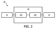
以下、方法10の詳細が、特に図1に示す方法を実施するためのシステム20のブロック図である図2と併せて記載される。
In the following, details of the
図2から見られる通り、本発明の一実施形態にかかる医療イメージングと情報表示のためのシステム20は医療イメージング装置21、処理装置22、及び表示装置23を有する。
As can be seen from FIG. 2, the
ここで、医療イメージング装置21はCTイメージング装置、MRイメージング装置、超音波イメージング装置であり得る。代替的に、医療イメージング装置21は複合モダリティイメージング装置であってもよい。例えば、これは一つの装置においてCTイメージングモダリティとMRIモダリティを実行することができるCT/MRI複合イメージング装置であり得る。以下、超音波イメージング装置が装置21の一実施例として使用される。
Here, the
さらに、処理装置22は医療イメージング装置21と結合され、CPU若しくはマイクロコントローラを伴うコンピュータ若しくは他の装置であり得る。処理装置22には、少なくともイメージング装置21からイメージングデータを処理するための導出ユニット221と構成ユニット222がある。導出ユニット221と構成ユニット222は処理装置22において個別ユニットとして示されるが、これらは一つの同じユニットで実現されてもよいことが当業者によって容易に理解されることに留意されたい。例えば、二つのユニットはコンピュータ内のCPUであり得る。
Further, the
表示装置23は任意の従来の表示装置であり得、例えば、コンピュータのディスプレイ若しくはコンソール内の個別表示画面であり得る。
The
はじめに、医療イメージング装置21は異なるイメージングモードにおける情報として患者などの対象のイメージングデータを取得する。上述の通り、イメージング装置21が超音波イメージング装置である場合、これは複数の異なるイメージングモードにおいて対象のイメージング面若しくはイメージングボリュームにおける各点のイメージングデータを取得する(図1のステップ11)。複数の異なる超音波イメージングモードは、Bモード、カラー、コントラスト、ストレイン超音波及び定量エラストグラフィ超音波を含むエラストグラフィ超音波を有するがそれらに限定されない。
First, the
次に、医療イメージング装置21と結合される導出ユニット221が、上記各点について、点のイメージングデータと、点に隣接する上記複数の点のうち少なくとも一つの他の点のイメージングデータとを既定モデルに適用することによって値を導出する(図1のステップ12)。
Next, a
さらに、構成ユニット222が導出値全てに基づいて画像を構成する(図1のステップ13)。
Further, the
ここで、既定モデルは対象に関する臨床医療アプリケーションに従って選択される。 Here, the default model is selected according to the clinical medical application for the subject.
一実施例において、既定モデルは機械学習ベースモデルであり得る。 In one embodiment, the default model may be a machine learning based model.
一実施例において、既定モデルは構成画像が臨床判断支援情報を医師に提供し得るような臨床判断支援(CDS)モデルであり得る。 In one example, the default model may be a clinical decision support (CDS) model such that the constituent images can provide clinical decision support information to the physician.
当業者によって理解され得る通り、CDSモデルは対象について診断情報を出力するモデルであり得る。これは臨床オブジェクトについて予め確立される若しくは予め訓練されるCDSモデルであり得るか、又は対象に関する臨床医療アプリケーションのために適切な既存のCDSモデルでもあり得る。 As can be appreciated by those skilled in the art, a CDS model can be a model that outputs diagnostic information about a subject. This can be a pre-established or pre-trained CDS model for clinical objects, or it can be an existing CDS model suitable for clinical medical applications on the subject.
一実施例において、CDSモデルは肝臓診断のために使用されるモデルであり得る。具体的に、医師が患者を肝疾患と診断するとき、超音波Bモードイメージング、カラー及びエラストグラフィからの情報に基づき、本発明の方法を用いて、医師は対象について肝疾患の確率を示す異なる場所において異なる強度の画像(若しくは画像シーケンス)を直接提供される。 In one example, the CDS model may be a model used for liver diagnosis. Specifically, when a doctor diagnoses a patient with liver disease, based on information from ultrasound B-mode imaging, color and elastography, using the method of the present invention, the doctor indicates the probability of liver disease for the subject. Different intensities of images (or image sequences) are directly provided at the location.
別の実施例では、CDSモデルは対象の血液供給機能に関する出力結果を提供し得る。医師が対象の臓器における血液供給機能を評価するとき、Bモード、カラー及びコントラストイメージングなどの異なる超音波モードの情報に基づき、三つのモードからのイメージングデータを同時に使用することによって、CDSモデルは全ての場所において臓器中のその場所における血液供給機能を示すスコア値を画像上に直接表示することができる。本発明の方法により、臨床アプリケーションのオブジェクトは医師のための関連"画像"を直接提供され、これは医師が可能性のある疾患についてROIを位置特定し、また表示画像全体から最適臨床判断支援を得ることもできるようにするのを支援し得る。 In another example, the CDS model may provide output results relating to the subject's blood supply function. When the physician evaluates blood supply function in the organ of interest, the CDS model is all based on the simultaneous use of imaging data from the three modes based on information of different ultrasound modes such as B mode, color and contrast imaging. The score value indicating the blood supply function in the organ can be directly displayed on the image. With the method of the present invention, clinical application objects are directly provided with relevant “images” for the physician, which allows the physician to locate the ROI for possible diseases and to assist in optimal clinical judgment from the entire displayed image. It can help to be able to get.
しかしながら、CDSモデルはそれに限定されない。当該技術分野で周知の通り、一部の種類のCDSモデルは医師が導出値若しくは構成画像に基づいて対象の診断結果若しくは健康状態を取得することができないようなものである。言い換えれば、CDSモデルの出力値は対象に関する構造的若しくは機能的情報であり得る。医師はこうした構造的若しくは機能的情報に基づいて直接対象の診断結果を得ることはできないが、この構造的若しくは機能的情報は医師を支援するのに役立つことができ、診断を容易にする。 However, the CDS model is not limited thereto. As is well known in the art, some types of CDS models are such that a physician cannot obtain a target's diagnostic results or health based on derived values or constituent images. In other words, the output value of the CDS model can be structural or functional information about the object. Although a physician cannot obtain a subject's diagnostic results directly based on such structural or functional information, this structural or functional information can help to assist the physician and facilitate diagnosis.
一実施例において、CDSモデルはBモード、カラーモード、及びエラストグラフィモードからのイメージングデータを利用することによってより明確な解剖学的構造を得るために使用され得る。解剖学的構造について、これは高強度のBモードエコー信号としてあらわれ得る。ここで使用される"高強度"という語は他のものにも対応し得るが、この場合これは高エコーエネルギーをあらわすのみである。カラーモードは血液情報をある程度まで提供し、超音波カラー画像の強い信号内部には構造がないことが多い。エラストグラフィモードは別の視点からある程度まで構造をあらわし得る弾性情報を提供する。解剖学的構造をイメージングするためのこれら三種類の情報とともに、それらを同時に"利用する"人工モデルが確立されるべきであり、出力画像は関心構造分布を直接示す。 In one embodiment, the CDS model can be used to obtain a clearer anatomy by utilizing imaging data from the B mode, color mode, and elastography mode. For anatomy, this can appear as a high intensity B-mode echo signal. As used herein, the term “high intensity” may correspond to others, but in this case this only represents high echo energy. The color mode provides blood information to some extent and often has no structure inside the strong signal of the ultrasound color image. The elastography mode provides elasticity information that can represent the structure to some extent from another viewpoint. Along with these three types of information for imaging anatomical structures, an artificial model that “uses” them simultaneously should be established and the output image directly shows the structure distribution of interest.
さらなる実施例において、CDSモデルはBモードとコントラストモードからのイメージングデータを利用することによって血管分布を得るために使用され得る。血管内部には血液がある。また血管はその独自構造を持ち、これは高強度のBモードエコー信号としてあらわされ得る。これらの二つの態様を同時に考慮することによって、その一方のみを考慮することによってよりも血管が良好に定義され得る。従って、二種類の情報により、人工モデルは血管である場所の確率を示すように訓練され得る。そして出力画像は血管分布を示す。 In a further embodiment, the CDS model can be used to obtain vascular distribution by utilizing imaging data from B mode and contrast mode. There is blood inside the blood vessels. The blood vessel has its own structure, which can be expressed as a high-intensity B-mode echo signal. By considering these two aspects simultaneously, blood vessels can be better defined than by considering only one of them. Thus, with two types of information, the artificial model can be trained to show the probability of where it is a blood vessel. The output image shows the blood vessel distribution.
さらに別の実施例において、CDSモデルはBモード、カラーモード、コントラストモード及びエラストグラフィモードからのイメージングデータを利用することによって組織(物質)画像を得るために使用され得る。一部の組織は多くの特徴を持ち、Bモード、カラー、コントラスト、及びエラストグラフィなどがこうした特徴の一つ若しくは一部をあらわし得る。それらの全てを考慮することにより、組織の種類がよく定義され得る。それらを全て考慮するために、人工モデルが確立されるべきである。そして出力画像は異なるアプリケーションに従って異なる組織分布を示し得る。 In yet another embodiment, the CDS model can be used to obtain tissue (material) images by utilizing imaging data from the B mode, color mode, contrast mode and elastography mode. Some tissues have many features, and B-mode, color, contrast, elastography, etc. can represent one or some of these features. By considering all of them, the type of organization can be well defined. In order to take them all into account, an artificial model should be established. The output image can then show different tissue distributions according to different applications.
ここで、ステップ12において、イメージング面若しくはイメージングボリュームにおける各点についての値は点それ自体のイメージングデータのみからではなく、点に隣接する少なくとも一つの他の点のイメージングデータにも基づいて導出されることに留意されたい。このように、導出値及び従って構成画像の品質のさらなる改良が実現され得る。
Here, in
当業者は、少なくとも一つの他の点の各々と点との間の距離が既定値を超えないことを容易に理解し得る。例えば、一実施例において、少なくとも一つの他の点は目標点に最も近い点であり得る。言い換えれば、それらはイメージング面若しくはイメージングボリュームにおいて目標点に関して右上、左上、右下、左下の点であり得る。 One skilled in the art can readily appreciate that the distance between each of the at least one other point and the point does not exceed a predetermined value. For example, in one embodiment, at least one other point can be the point closest to the target point. In other words, they can be the upper right, upper left, lower right, lower left points with respect to the target point in the imaging plane or imaging volume.
次に、表示装置23は構成画像をユーザに出力する(図1のステップ14)。
Next, the
従来の画像処理法と比較して、本発明にかかる方法10は医師が異なるモードにおいてオブジェクトを示すために関心領域(ROI)を選択し、そして情報自体を提供するために関連分析又はコンピュータアルゴリズムを適用することを要求せず、その結果概して医師の負担を大幅に軽減する。
Compared to conventional image processing methods, the
さらに、本発明にかかる方法ではイメージング面若しくはイメージングボリュームにおける各点が値を持ち、これは点のイメージングデータと点に隣接する少なくとも一つの他の点のイメージングデータとに従って既定医療アプリケーション関連モデルから出力され、そして全ての点の全導出値に基づいて画像が構成されてユーザに表示されるので、方法は医師にとってリアルタイムスクリーニングを可能にする。 Further, in the method according to the present invention, each point in the imaging plane or imaging volume has a value, which is output from the predefined medical application related model according to the imaging data of the point and the imaging data of at least one other point adjacent to the point. And the method allows the physician to perform real-time screening since an image is constructed and displayed to the user based on all derived values of all points.
例えば、超音波スクリーニング中、医師がプローブを特定場所へ動かすとき、視野内の各ピクセルについての導出値はリアルタイムに医師に提示される画像として鮮明に表示され、医師がプローブの角度若しくは位置を変更するとき、提示画像はそれに従って更新される。 For example, during ultrasound screening, when the doctor moves the probe to a specific location, the derived values for each pixel in the field of view are clearly displayed as an image presented to the doctor in real time, and the doctor changes the angle or position of the probe The presentation image is updated accordingly.
さらに、本発明の方法は臨床オブジェクトについての情報をピクセルレベルで直接伝える画像をあらわし得るので、医師は従来のROI法と比較して高解像度の画像を提供され、従ってオブジェクトを見過ごさない。 Furthermore, since the method of the present invention can represent an image that conveys information about clinical objects directly at the pixel level, the physician is provided with a higher resolution image compared to the conventional ROI method, thus not overlooking the object.
さらに、本発明にかかる方法において、イメージング面若しくはイメージングボリュームにおける各点についての値は点それ自体のイメージングデータのみからではなく、点に隣接する少なくとも一つの他の点のイメージングデータにも基づいて導出される。このように、導出値及び従って構成画像の品質のさらなる改良が実現され得る。 Furthermore, in the method according to the invention, the value for each point in the imaging plane or volume is derived not only from the imaging data of the point itself but also from the imaging data of at least one other point adjacent to the point. Is done. In this way, further improvements in the derived values and thus the quality of the constituent images can be realized.
一実施例において、全導出値に基づいて画像を構成するステップ13は、画像中の各点がイメージング面における対応する点の値に従って異なる輝度若しくは色を持つように画像を構成するステップを有し得る。
In one embodiment, the
例えば、イメージング面における点の値が高い場合、取得画像における対応する点についての輝度は高くなる。代替的に、画像面における点の値が高い場合、取得画像における対応する点についての輝度は低くなる。 For example, when the value of a point on the imaging surface is high, the brightness for the corresponding point in the acquired image is high. Alternatively, if the value of a point on the image plane is high, the brightness for the corresponding point in the acquired image is low.
このように、医師はより明確な表示を提供され得るので、追加観察若しくは評価を要する部分を容易に同定することができる。 In this way, the physician can be provided with a clearer display, so that a portion that requires additional observation or evaluation can be easily identified.
本発明の原理及び本発明にかかる方法の基本フローチャートは上記に詳述されている。次に、ステップ11がその要件を明確にするために詳細に説明される。
The principle of the invention and the basic flow chart of the method according to the invention have been described in detail above.
上述の通り、ステップ11において、複数の異なるイメージングモードにおいて対象のイメージング面若しくはイメージングボリュームにおける各点のイメージングデータが取得されるべきである(図1のステップ11)。
As described above, in
"異なるイメージングモードにおける各点のイメージングデータ"という表現を使用する理由は、ピクセルレベルの画像処理を実行するために、次のプロセスについて全ての場所(点)において情報の対応を保証するべく全モード間でピクセルレベルの対応が得られるべきであるからである。CT及びMRイメージングの場合、そのイメージング原理のために、全モード間のピクセルレベルの対応が実現可能であると思われる。しかしながら超音波イメージングの場合これは非常に難しい。 The reason for using the expression "imaging data for each point in different imaging modes" is to perform pixel level image processing in all modes to ensure correspondence of information at every location (point) for the next process This is because a pixel level correspondence should be obtained between them. In the case of CT and MR imaging, it seems that pixel level correspondence between all modes is feasible due to its imaging principle. However, this is very difficult for ultrasound imaging.
具体的には、現在、超音波システムはスキャンモード変化の際にピクセルレベルの対応を直接提供することができない。異なるモード(Bモード、カラー、コントラスト、ストレイン、及び定量エラストグラフィ)によって、画像は全く異なる。従って従来のレジストレーションアルゴリズムはここではもはや適切でない。 Specifically, currently, ultrasound systems cannot directly provide pixel level correspondence upon scan mode changes. With different modes (B mode, color, contrast, strain, and quantitative elastography), the images are quite different. Thus, conventional registration algorithms are no longer appropriate here.
本発明の背景技術において述べた通り、一部の超音波イメージングモードの場合、ピクセルレベルの対応を伴って異なるモダリティを同時にイメージングすることが実現されるとみなされ得る。例えば、カラーイメージングとして、カラーモダリティ用の無線周波数(RF)信号シーケンスはBモードイメージングモダリティを得るためにも使用されることができる。これに基づき、カラー及びBモード間のピクセルレベルの対応がリアルタイムイメージングのために実現される。しかしながら、これらの同時モダリティを使用するために、今日これらは単に表示のためにピクセルレベルで組み合わされ、そして医師はそれらを従来のイメージングモダリティとして使用し、それらを従来の方法で処理する必要がある。従って、高次元データをうまく同時処理する方法は依然医師にとって困難な課題である。一方、こうした種類の現在のイメージングモダリティのRF信号は異なるイメージングモードを生成するには制限が多過ぎることが多い。上記信号の数は一般にたった2であり、これは十分なイメージング情報を提供してその後のCDS処理を実現するためには不十分であり得る。超音波において広範囲のイメージングモードを考慮するとき、その生のイメージングRFデータは全く異なる。 As described in the background of the present invention, for some ultrasound imaging modes, it may be considered that simultaneous imaging of different modalities with pixel level correspondence is realized. For example, as color imaging, a radio frequency (RF) signal sequence for a color modality can also be used to obtain a B-mode imaging modality. Based on this, a pixel level correspondence between color and B modes is realized for real time imaging. However, to use these simultaneous modalities, today they are simply combined at the pixel level for display, and the physician needs to use them as conventional imaging modalities and process them in a conventional manner . Therefore, a method for successfully simultaneously processing high-dimensional data is still a difficult task for doctors. On the other hand, these types of current imaging modality RF signals are often too restrictive to generate different imaging modes. The number of such signals is generally only 2, which may be insufficient to provide sufficient imaging information to implement subsequent CDS processing. When considering a wide range of imaging modes in ultrasound, the raw imaging RF data is quite different.
従って、上述の超音波イメージングに関する問題を考慮して、本発明の発明者らはさらに全ての超音波イメージングモード間でピクセルレベルの対応を得るために超音波イメージング装置のための送信信号シーケンスを特異的に設計することを提案する。 Thus, in view of the above-mentioned problems with ultrasound imaging, the inventors of the present invention further specify a transmission signal sequence for an ultrasound imaging device in order to obtain a pixel level correspondence between all ultrasound imaging modes. It is proposed to design it dynamically.
原則的に、本発明の発明者らは、異なるイメージングモードにおけるイメージングデータが同時に取得され、イメージングデータの点レベルの対応が異なるイメージングモード間で確立されるように、超音波イメージング装置のための送信信号シーケンスが送信信号の時系列、信号エネルギー、及びビーム形成パターンに従って設計され得ることを発見した。 In principle, the inventors of the present invention can transmit for ultrasound imaging devices so that imaging data in different imaging modes are acquired simultaneously and point-level correspondence of the imaging data is established between the different imaging modes. It has been discovered that the signal sequence can be designed according to the time series of transmitted signals, signal energy, and beamforming pattern.
一実施例において、イメージングモードは五つのモード:Bモード、カラー、コントラスト、ストレイン及びエラストグラフィのうち少なくとも二つを有する。 In one embodiment, the imaging mode has at least two of five modes: B mode, color, contrast, strain, and elastography.
さらなる実施例において、五つの超音波イメージングモード全てが使用される場合、送信信号シーケンスは、第二の典型的な超音波面送信(plane‐transmit)の位相が反転される二つの高エネルギー及び高集束超音波面送信で補間される三つの典型的な超音波面送信を有するように設計される。 In a further embodiment, if all five ultrasound imaging modes are used, the transmitted signal sequence is two high energy and high inversion phases of the second typical plane-transmit. Designed to have three typical ultrasonic surface transmissions interpolated with focused ultrasonic surface transmissions.
一般に、一つのモードにおけるイメージングのための送信信号シーケンスは多くの超音波送信から成るとみなされ得る。異なるモードによって、必要な送信の組み合わせは異なる。例えば、Bモードイメージングは少なくとも一つの典型的な超音波面送信を要する。カラーイメージングは少なくとも三つの典型的な超音波面送信を要するはずである。ストレインイメージングは少なくとも二つの典型的な超音波面送信を要する。せん断波定量エラストグラフィは少なくとも二つの高エネルギー及び高集束超音波面送信を要する。コントラストイメージングは少なくとも二つの典型的な超音波面送信と一つの逆面送信を要する。本発明の方法の場合、異なるモードの同時イメージングが要求される。従来の送信ハードウェアが変わらず、上述のモードの全送信信号が異なる送信信号シーケンスのカスケードを作るようにただ直接組み合わされる場合、総送信信号シーケンスについて少なくとも1+3+2+2+3=11の面送信があることになる。多過ぎる面送信から成る送信信号シーケンスはイメージングについて低フレームレートをもたらす可能性があり、さらに"異なるモードの情報の同時取得"に影響する可能性がある。 In general, a transmission signal sequence for imaging in one mode can be considered to consist of many ultrasound transmissions. Different modes require different combinations of transmissions. For example, B-mode imaging requires at least one typical ultrasonic surface transmission. Color imaging should require at least three typical ultrasonic surface transmissions. Strain imaging requires at least two typical ultrasonic surface transmissions. Shear wave quantitative elastography requires at least two high energy and highly focused ultrasonic surface transmissions. Contrast imaging requires at least two typical ultrasonic surface transmissions and one reverse surface transmission. In the method of the present invention, simultaneous imaging in different modes is required. If the conventional transmission hardware is unchanged and all the transmitted signals in the above modes are simply combined directly to create a cascade of different transmitted signal sequences, there will be at least 1 + 3 + 2 + 2 + 3 = 11 surface transmissions for the total transmitted signal sequence. . A transmitted signal sequence consisting of too many surface transmissions can result in a low frame rate for imaging and can also affect “simultaneous acquisition of information in different modes”.
この考察に基づき、送信信号シーケンス及び関連ハードウェアは特異的に設計されるべきである。基本原理は一つのモードに対する面送信が他のモードのイメージングのためにも適用可能であるべきであるということであり、そのために一つの信号シーケンスにおける詳細な出現順は変化し得る。また上記実施例に関して、一つの可能なRF信号送信シーケンスは、第二の典型的な超音波面送信が位相において反転されるべきである、二つの高エネルギー及び高集束超音波面送信で補間される三つの典型的な超音波面送信であり得る。受信のために、第一の典型的な超音波面送信が典型的にはBモードイメージングを生成するために受信される。第一及び第三の典型的な超音波面送信は典型的にはストレインモードを生成するために受信される。カラーモードを生成するために第一及び第三の典型的な超音波面送信が典型的に受信され、第二の典型的な超音波面送信が逆に受信される。二つの高エネルギー及び高集束超音波面送信について、それらの各々の直後に高速受信スキャンが実行されるべきであり、そしてせん断波エラストグラフィが取得され得る。コントラストモードについて、コントラスト画像情報を生成するために三つの典型的な超音波面送信が典型的に受信される。シーケンスにおける面送信の総数はたった5であることがわかる。 Based on this consideration, the transmit signal sequence and associated hardware should be specifically designed. The basic principle is that surface transmission for one mode should be applicable for imaging of other modes, so the detailed order of appearance in one signal sequence can change. Also for the above embodiment, one possible RF signal transmission sequence is interpolated with two high energy and high focused ultrasound surface transmissions, where the second typical ultrasound surface transmission should be inverted in phase. There can be three typical ultrasonic surface transmissions. For reception, a first exemplary ultrasound plane transmission is typically received to generate B-mode imaging. The first and third exemplary ultrasonic surface transmissions are typically received to generate a strain mode. The first and third exemplary ultrasonic surface transmissions are typically received to generate the color mode, and the second exemplary ultrasonic surface transmission is received in reverse. For two high energy and highly focused ultrasound surface transmissions, a fast receive scan should be performed immediately after each of them, and shear wave elastography can be acquired. For the contrast mode, three typical ultrasonic surface transmissions are typically received to generate contrast image information. It can be seen that the total number of surface transmissions in the sequence is only 5.
異なるモード全てが同じ生の送信信号シーケンスに由来するので、異なるモード間のピクセルレベルの対応がうまく得られる。異なるハードウェア特徴のために、リアルタイムイメージングのための面送信の最大許容数は異なる可能性があり、従ってより多くの面送信が一つのモードのために使用され得る。しかし本発明の方法の基本設計原理は同じままであるべきである。 Since all the different modes are derived from the same raw transmitted signal sequence, a pixel level correspondence between the different modes is successfully obtained. Due to different hardware features, the maximum allowed number of surface transmissions for real-time imaging can be different, so more surface transmissions can be used for one mode. However, the basic design principle of the method of the present invention should remain the same.
図2は本発明にかかるシステム20の基本ブロック図を示すのみであるが、上記方法10における各ステップに対応して、関連方法ステップを実行する対応ユニットがあり得ることが当業者によって容易に理解され得る。
FIG. 2 only shows a basic block diagram of the
処理装置22に含まれるユニット221及び222について、一実施例では、処理装置22自体がCPUとメモリを伴うパーソナルコンピュータ、シングルチップマイクロコンピュータ又はCPU(すなわち処理ユニット)単独であり得る。従って、その中に含まれる各ユニットはソフトウェア若しくはコンピュータ可読命令として実現され得る。
Regarding the
しかしながら、当業者によって容易に理解される通り、各ユニットは、ハードウェアエンティティであってもよい。言い換えれば、処理装置22は別個のハードウェアモジュールから構成され得る。ユニットの各々は単一プロセッサ若しくは複数のプロセッサによって実現され得る。
However, as will be readily appreciated by those skilled in the art, each unit may be a hardware entity. In other words, the
本発明において示される方法10のステップは上述のステップに限定されないべきであることに留意されたい。請求される本発明の様々な態様はこれら特定の詳細から外れる他の実施例において実施されてもよいことが当業者に明らかであろう。
It should be noted that the steps of the
さらに、ROIが明細書を通じて使用されるが、当業者はROI"関心領域"という語が2Dシナリオの場合に使用され、一方VOI、すなわち"関心ボリューム"という語が3Dの場合に使用されることを容易に理解し得る。 Further, although ROI is used throughout the specification, those skilled in the art will recognize that the term ROI “region of interest” is used in the case of a 2D scenario, while the term VOI, ie “volume of interest” is used in the case of 3D. Can be easily understood.
さらに、当業者によって容易に理解され得る通り、複数の手段を列挙する装置クレームにおいて、これら手段の複数はハードウェアの一つの同じ項目によって具体化されることができる。特定の手段が相互に異なる従属クレームにおいて列挙されるという単なる事実はこれら手段の組み合わせが有利に使用されることができないことを示さない。 Further, as can be readily understood by one skilled in the art, in a device claim enumerating a plurality of means, a plurality of these means may be embodied by one and the same item of hardware. The mere fact that certain measures are recited in mutually different dependent claims does not indicate that a combination of these measured cannot be used to advantage.
上述の実施形態は本発明を限定するのではなく、当業者は添付のクレームの範囲から逸脱することなく代替的実施形態を設計することができるであろうことが留意されるべきである。クレーム中、括弧の間に置かれる任意の参照記号はクレームを限定するものと解釈されてはならない。"有する"という語はクレーム中若しくは記載中に列挙されない要素若しくはステップの存在を除外しない。ある要素に先行する"a"若しくは"an"という語はかかる要素の複数の存在を除外しない。複数のユニットを列挙するシステムクレームにおいて、これらユニットの複数はソフトウェア及び/又はハードウェアの一つの同じ項目によって具体化されることができる。第一、第二及び第三などの語の使用はいかなる順序も示さない。これらの語は名前として解釈されるものとする。 It should be noted that the above-described embodiments do not limit the present invention, and that those skilled in the art will be able to design alternative embodiments without departing from the scope of the appended claims. In the claims, any reference signs placed between parentheses shall not be construed as limiting the claim. The word “comprising” does not exclude the presence of elements or steps not listed in a claim or in the description. The word “a” or “an” preceding an element does not exclude the presence of a plurality of such elements. In a system claim enumerating multiple units, multiple of these units may be embodied by one and the same item of software and / or hardware. The use of words such as first, second and third does not indicate any order. These words shall be interpreted as names.
Claims (15)
複数の異なるイメージングモードの各モードにおいて対象のイメージング面若しくはイメージングボリュームにおける複数の点の各点のイメージングデータを取得するための医療イメージング装置と、
処理装置であって、
前記複数の点の前記各点について、前記各モードにおける前記点のイメージングデータと、前記各モードにおける前記点に隣接する前記複数の点のうち少なくとも一つの他の点のイメージングデータとを既定モデルに適用することによって、値を導出するための導出ユニットであって、前記既定モデルは前記対象に関する臨床医療アプリケーションに従って選択される、導出ユニットと、
前記導出された値全てに基づいて画像を構成するための構成ユニットと
を有する処理装置と、
前記構成された画像をユーザに表示するための表示装置と
を有するシステム。 A system for medical imaging and information display,
A medical imaging device for acquiring imaging data of each of a plurality of points on a target imaging surface or imaging volume in each of a plurality of different imaging modes;
A processing device comprising:
For each point of the plurality of points, imaging data of the point in each mode and imaging data of at least one other point among the plurality of points adjacent to the point in each mode are used as a default model. A derivation unit for deriving a value by applying, wherein the predetermined model is selected according to a clinical medical application for the subject;
A processing unit comprising: a configuration unit for composing an image based on all of the derived values;
And a display device for displaying the constructed image to a user.
前記送信信号シーケンスが、第二の典型的な超音波面送信の位相が反転される、二つの高エネルギー及び高集束超音波面送信で補間される三つの典型的な超音波面送信を有する、請求項4に記載のシステム。 The plurality of different imaging modes has a total of five modes;
The transmitted signal sequence has three exemplary ultrasonic surface transmissions interpolated with two high energy and high focused ultrasonic surface transmissions, wherein the phase of the second exemplary ultrasonic surface transmission is reversed. The system according to claim 4.
医療イメージング装置の複数の異なるイメージングモードの各モードにおいて対象のイメージング面若しくはイメージングボリュームにおける複数の点の各点のイメージングデータを取得するステップと、
前記各点について、前記各モードにおける前記点のイメージングデータと、前記各モードにおける前記点に隣接する前記複数の点のうち少なくとも一つの他の点のイメージングデータとを既定モデルに適用することによって、値を導出するステップであって、前記既定モデルが前記対象に関する臨床医療アプリケーションに従って選択される、ステップと、
前記導出された値全てに基づいて画像を構成するステップと、
前記構成された画像をユーザに表示するステップと
を有する方法。 A method of medical imaging and information display,
Acquiring imaging data for each of a plurality of points on a target imaging surface or imaging volume in each of a plurality of different imaging modes of the medical imaging device;
For each point, by applying imaging data of the point in each mode and imaging data of at least one other point of the plurality of points adjacent to the point in each mode to a predetermined model, Deriving a value, wherein the default model is selected according to a clinical medical application for the subject;
Constructing an image based on all of the derived values;
Displaying the constructed image to a user.
前記画像中の各点が前記イメージング面における対応する点の値に従って異なる輝度若しくは色を持つように画像を構成するステップを有する、請求項9に記載の方法。 Constructing an image based on all of the derived values;
The method of claim 9, comprising constructing the image such that each point in the image has a different brightness or color according to the value of the corresponding point in the imaging plane.
Applications Claiming Priority (5)
| Application Number | Priority Date | Filing Date | Title |
|---|---|---|---|
| CN2013081206 | 2013-08-09 | ||
| CNPCT/CN2013/081206 | 2013-08-09 | ||
| EP13194039.7 | 2013-11-22 | ||
| EP13194039 | 2013-11-22 | ||
| PCT/EP2014/067139 WO2015018946A1 (en) | 2013-08-09 | 2014-08-11 | Method and system for medical imaging and information display |
Publications (2)
| Publication Number | Publication Date |
|---|---|
| JP2016527043A true JP2016527043A (en) | 2016-09-08 |
| JP2016527043A5 JP2016527043A5 (en) | 2017-09-14 |
Family
ID=51302975
Family Applications (1)
| Application Number | Title | Priority Date | Filing Date |
|---|---|---|---|
| JP2016532702A Pending JP2016527043A (en) | 2013-08-09 | 2014-08-11 | Method and system for medical imaging and information display |
Country Status (4)
| Country | Link |
|---|---|
| US (2) | US10226235B2 (en) |
| EP (1) | EP3030156A1 (en) |
| JP (1) | JP2016527043A (en) |
| WO (1) | WO2015018946A1 (en) |
Families Citing this family (3)
| Publication number | Priority date | Publication date | Assignee | Title |
|---|---|---|---|---|
| US10226235B2 (en) * | 2013-08-09 | 2019-03-12 | Koninklijke Philips N.V. | Method and system for medical imaging and information display |
| JP6290336B2 (en) * | 2016-08-25 | 2018-03-07 | 株式会社日立製作所 | Ultrasonic diagnostic equipment |
| CN108171272A (en) * | 2018-01-12 | 2018-06-15 | 上海东软医疗科技有限公司 | A kind of evaluation method and device of Medical Imaging Technology |
Citations (5)
| Publication number | Priority date | Publication date | Assignee | Title |
|---|---|---|---|---|
| JP2000316860A (en) * | 1999-04-23 | 2000-11-21 | General Electric Co <Ge> | Three-dimensional flow imaging method and device using coded excitation |
| US6186949B1 (en) * | 1998-03-31 | 2001-02-13 | General Electric Company | Method and apparatus for three-dimensional flow imaging using coded excitation |
| JP2001299765A (en) * | 2000-02-17 | 2001-10-30 | Ge Yokogawa Medical Systems Ltd | Method for displaying ultrasonic image and ultrasonographic instrument |
| JP2007524461A (en) * | 2003-06-25 | 2007-08-30 | シーメンス メディカル ソリューションズ ユーエスエー インコーポレイテッド | Mammography automatic diagnosis and decision support system and method |
| JP2007527743A (en) * | 2004-02-03 | 2007-10-04 | シーメンス メディカル ソリューションズ ユーエスエー インコーポレイテッド | System and method for automatic diagnosis and decision support for heart related diseases and conditions |
Family Cites Families (5)
| Publication number | Priority date | Publication date | Assignee | Title |
|---|---|---|---|---|
| US7569015B2 (en) * | 2005-07-15 | 2009-08-04 | General Electric Company | Integrated physiology and imaging workstation |
| US20070016029A1 (en) * | 2005-07-15 | 2007-01-18 | General Electric Company | Physiology workstation with real-time fluoroscopy and ultrasound imaging |
| US8303502B2 (en) | 2007-03-06 | 2012-11-06 | General Electric Company | Method and apparatus for tracking points in an ultrasound image |
| CN103429167A (en) * | 2011-01-28 | 2013-12-04 | 心脏技术有限公司 | System, method and device for automatic and autonomous determination of hemodynamic and cardiac parameters using ultrasound |
| US10226235B2 (en) * | 2013-08-09 | 2019-03-12 | Koninklijke Philips N.V. | Method and system for medical imaging and information display |
-
2014
- 2014-08-11 US US14/910,718 patent/US10226235B2/en active Active
- 2014-08-11 EP EP14750467.4A patent/EP3030156A1/en not_active Withdrawn
- 2014-08-11 JP JP2016532702A patent/JP2016527043A/en active Pending
- 2014-08-11 WO PCT/EP2014/067139 patent/WO2015018946A1/en active Application Filing
-
2019
- 2019-01-25 US US16/257,524 patent/US11076832B2/en active Active
Patent Citations (6)
| Publication number | Priority date | Publication date | Assignee | Title |
|---|---|---|---|---|
| US6186949B1 (en) * | 1998-03-31 | 2001-02-13 | General Electric Company | Method and apparatus for three-dimensional flow imaging using coded excitation |
| JP2000316860A (en) * | 1999-04-23 | 2000-11-21 | General Electric Co <Ge> | Three-dimensional flow imaging method and device using coded excitation |
| JP2001299765A (en) * | 2000-02-17 | 2001-10-30 | Ge Yokogawa Medical Systems Ltd | Method for displaying ultrasonic image and ultrasonographic instrument |
| JP2007524461A (en) * | 2003-06-25 | 2007-08-30 | シーメンス メディカル ソリューションズ ユーエスエー インコーポレイテッド | Mammography automatic diagnosis and decision support system and method |
| US20100121178A1 (en) * | 2003-06-25 | 2010-05-13 | Sriram Krishnan | Systems and Methods for Automated Diagnosis and Decision Support for Breast Imaging |
| JP2007527743A (en) * | 2004-02-03 | 2007-10-04 | シーメンス メディカル ソリューションズ ユーエスエー インコーポレイテッド | System and method for automatic diagnosis and decision support for heart related diseases and conditions |
Also Published As
| Publication number | Publication date |
|---|---|
| US20160174943A1 (en) | 2016-06-23 |
| US11076832B2 (en) | 2021-08-03 |
| US20190150896A1 (en) | 2019-05-23 |
| US10226235B2 (en) | 2019-03-12 |
| EP3030156A1 (en) | 2016-06-15 |
| WO2015018946A1 (en) | 2015-02-12 |
Similar Documents
| Publication | Publication Date | Title |
|---|---|---|
| US10231704B2 (en) | Method for acquiring ultrasonic data | |
| US9489921B2 (en) | Method and apparatus for displaying plurality of different images of object | |
| US10772606B2 (en) | Method and apparatus for displaying ultrasound images | |
| JP5984243B2 (en) | Ultrasonic diagnostic apparatus, medical image processing apparatus, and program | |
| US10922874B2 (en) | Medical imaging apparatus and method of displaying medical image | |
| JP6382050B2 (en) | Medical image diagnostic apparatus, image processing apparatus, image processing method, and image processing program | |
| US20130331697A1 (en) | Method and apparatus for displaying three-dimensional ultrasonic image and two-dimensional ultrasonic image | |
| EP2892024B1 (en) | Method and medical imaging apparatus for displaying medical images | |
| US11076832B2 (en) | Method and system for medical imaging and information display | |
| KR102278893B1 (en) | Medical image processing apparatus and medical image registration method using the same | |
| KR101690654B1 (en) | Medical imaging apparatus and medical image processing method thereof | |
| JP2004057411A (en) | Method for preparing visible image for medical use | |
| JP2013051998A (en) | Ultrasonic diagnostic apparatus and control program for ultrasonic diagnostic apparatus | |
| JP6863774B2 (en) | Ultrasound diagnostic equipment, image processing equipment and image processing programs | |
| KR101107478B1 (en) | Ultrasound system and method for forming a plurality of 3 dimensional ultrasound images | |
| CN105451662B (en) | The method and system shown for medical imaging and information | |
| CN108877922A (en) | Lesion degree judges system and method | |
| EP2352122B1 (en) | Ultrasonic diagnostic apparatus | |
| JP2016093302A (en) | Medical image diagnostic apparatus, image processing apparatus and image processing program | |
| JP2008206965A (en) | Medical image forming device, method and program | |
| JP6587583B2 (en) | Ultrasonic imaging apparatus, ultrasonic imaging method, and combined state evaluation apparatus | |
| JP6740051B2 (en) | Ultrasonic diagnostic device, medical image processing device, and medical image processing program | |
| KR102578754B1 (en) | Method of displaying a ultrasound image and apparatus thereof | |
| JP7304947B2 (en) | ultrasonic control unit |
Legal Events
| Date | Code | Title | Description |
|---|---|---|---|
| RD04 | Notification of resignation of power of attorney |
Free format text: JAPANESE INTERMEDIATE CODE: A7424 Effective date: 20170214 |
|
| A521 | Request for written amendment filed |
Free format text: JAPANESE INTERMEDIATE CODE: A523 Effective date: 20170801 |
|
| A621 | Written request for application examination |
Free format text: JAPANESE INTERMEDIATE CODE: A621 Effective date: 20170801 |
|
| A977 | Report on retrieval |
Free format text: JAPANESE INTERMEDIATE CODE: A971007 Effective date: 20180323 |
|
| A131 | Notification of reasons for refusal |
Free format text: JAPANESE INTERMEDIATE CODE: A131 Effective date: 20180502 |
|
| A521 | Request for written amendment filed |
Free format text: JAPANESE INTERMEDIATE CODE: A523 Effective date: 20180802 |
|
| A02 | Decision of refusal |
Free format text: JAPANESE INTERMEDIATE CODE: A02 Effective date: 20190129 |