JP2016525786A - Connector for harsh environments with seal closure assist device - Google Patents

Connector for harsh environments with seal closure assist device Download PDF

Info

Publication number
JP2016525786A
JP2016525786A JP2016531618A JP2016531618A JP2016525786A JP 2016525786 A JP2016525786 A JP 2016525786A JP 2016531618 A JP2016531618 A JP 2016531618A JP 2016531618 A JP2016531618 A JP 2016531618A JP 2016525786 A JP2016525786 A JP 2016525786A
Authority
JP
Japan
Prior art keywords
receptacle
plug
unit
seal
actuator
Prior art date
Legal status (The legal status is an assumption and is not a legal conclusion. Google has not performed a legal analysis and makes no representation as to the accuracy of the status listed.)
Pending
Application number
JP2016531618A
Other languages
Japanese (ja)
Other versions
JP2016525786A5 (en
Inventor
エム. クレッチマー,ジャスティン
エム. クレッチマー,ジャスティン
ティー. ジョーンズ,リチャード
ティー. ジョーンズ,リチャード
エム. ナゲンガスト,ケンネス
エム. ナゲンガスト,ケンネス
Original Assignee
テレダイン インストゥルメンツ,インコーポレイテッド
Priority date (The priority date is an assumption and is not a legal conclusion. Google has not performed a legal analysis and makes no representation as to the accuracy of the date listed.)
Filing date
Publication date
Application filed by テレダイン インストゥルメンツ,インコーポレイテッド, テレダイン インストゥルメンツ,インコーポレイテッド filed Critical テレダイン インストゥルメンツ,インコーポレイテッド
Publication of JP2016525786A publication Critical patent/JP2016525786A/en
Publication of JP2016525786A5 publication Critical patent/JP2016525786A5/ja
Pending legal-status Critical Current

Links

Images

Classifications

    • GPHYSICS
    • G02OPTICS
    • G02BOPTICAL ELEMENTS, SYSTEMS OR APPARATUS
    • G02B6/00Light guides; Structural details of arrangements comprising light guides and other optical elements, e.g. couplings
    • G02B6/46Processes or apparatus adapted for installing or repairing optical fibres or optical cables
    • G02B6/50Underground or underwater installation; Installation through tubing, conduits or ducts
    • G02B6/506Underwater installation
    • GPHYSICS
    • G02OPTICS
    • G02BOPTICAL ELEMENTS, SYSTEMS OR APPARATUS
    • G02B6/00Light guides; Structural details of arrangements comprising light guides and other optical elements, e.g. couplings
    • G02B6/24Coupling light guides
    • G02B6/36Mechanical coupling means
    • G02B6/38Mechanical coupling means having fibre to fibre mating means
    • G02B6/3807Dismountable connectors, i.e. comprising plugs
    • G02B6/381Dismountable connectors, i.e. comprising plugs of the ferrule type, e.g. fibre ends embedded in ferrules, connecting a pair of fibres
    • G02B6/3816Dismountable connectors, i.e. comprising plugs of the ferrule type, e.g. fibre ends embedded in ferrules, connecting a pair of fibres for use under water, high pressure connectors

Landscapes

  • Physics & Mathematics (AREA)
  • General Physics & Mathematics (AREA)
  • Optics & Photonics (AREA)
  • Connector Housings Or Holding Contact Members (AREA)
  • Quick-Acting Or Multi-Walled Pipe Joints (AREA)
  • Mechanical Coupling Of Light Guides (AREA)

Abstract

水中ローリングシールコネクタアセンブリは、レセプタクルユニおよびプラグユニットの正面に装着された1つまたは複数のローリングシール(88,32)を有する解放可能に嵌合可能なプラグ(10)およびレセプタクル(12)を有する。ローリングシールは、1つまたは複数の接点を備えるそれぞれのユニット内の1つまたは複数のチャンバをシールする閉位置と、一方のユニット内の接点がシール開口部を通り、他方のユニット内の接点と係合することが可能となるようシールを通るボアが開放される開位置と、の間で前後に回転可能である。アクチュエータ(128)は嵌合時には開位置へと、上阿波世界女児には閉位置へと、ローリングシールを自動的に回転させる。少なくとも1つのアクチュエータ支援装置(200)がプラグユニットおよびレセプタクルユニットのうちの一方のユニットに配置され、嵌合解放時に閉位置へと戻すためにシールを付勢するために当該ユニット内のローリングシールと結合される。【選択図】図6The underwater rolling seal connector assembly has a releasably matable plug (10) and receptacle (12) having one or more rolling seals (88, 32) mounted in front of the receptacle uni and plug unit. . A rolling seal is a closed position that seals one or more chambers in each unit with one or more contacts, a contact in one unit passes through the seal opening, and a contact in the other unit It can be rotated back and forth between an open position in which the bore through the seal is opened so that it can be engaged. The actuator (128) automatically rotates the rolling seal to the open position when mated and to the closed position for the world girls. At least one actuator support device (200) disposed on one of the plug unit and the receptacle unit, and a rolling seal in the unit for biasing the seal to return to the closed position upon release of the mating Combined. [Selection] Figure 6

Description

本発明は全般に、海面下環境などの過酷な環境で使用するための電気、光、または光電用のコネクタに関し、さらに詳細には、係るコネクタ内のシール閉止アクチュエータに関する。   The present invention relates generally to electrical, optical, or photoelectric connectors for use in harsh environments such as subsea environments, and more particularly to seal closure actuators within such connectors.

苛酷な環境で電気ケーブルおよび光ケーブルを接続するためのコネクタには多くの種類が存在する。1つの種類は、海中で、嵌合させるため、および嵌合を解放するためのコネクタである。係る水中コネクタは通常、1つまたは複数の接点プローブを備えるプラグユニットと、接点プローブと係合するための等しい個数のレセプタクル接点または接続部を備える、レセプタクルユニットと、を備え、接点プローブは、プラグユニットおよびレセプタクルユニットが一緒に接続されるとき、レセプタクルユニットに延びる。通常、接点または接続部は、誘電性流体を備えるシールされたチャンバに含まれ、プローブは、1つまたは複数の通常はシールされている開口部を介して、チャンバに進入する。係るユニットを設計する際の1つの主要な問題は、嵌合および嵌合の解放が反復された後においてさえ接点チャンバから海水を適切に排出するシールを提供することであり、その他にも、チャンバから誘電性流体が漏出することを防止することである。   There are many types of connectors for connecting electrical and optical cables in harsh environments. One type is a connector for mating and for releasing mating in the sea. Such underwater connectors typically comprise a plug unit comprising one or more contact probes and a receptacle unit comprising an equal number of receptacle contacts or connections for engaging the contact probes, the contact probe comprising a plug When the unit and the receptacle unit are connected together, they extend into the receptacle unit. Typically, the contacts or connections are contained in a sealed chamber with a dielectric fluid, and the probe enters the chamber through one or more normally sealed openings. One major problem in designing such units is to provide a seal that properly drains seawater from the contact chamber even after repeated mating and mating release, It is to prevent the dielectric fluid from leaking out.

この目的を達成するために、過去にいくつかの異なるシール機構が提案されてきた。このようなシール機構の1つは接点チャンバへの開口部を有し、この接点チャンバは弾性状括約機構により包囲された弾性状管状入口を備え、弾性状括約機構は、プラグユニットおよびレセプタクルユニットの嵌合が解放された状態にあるとき、入口を括約して閉止する。嵌合された状態では括約機構は進入しつつあるプローブに抗して括約し、それによりシールが形成される。この種のシールは良好に機能する場合もあるが、短所も確かに存在する。1つの短所は、このシールが過酷な状況下では良好に機能しないことである。他の短所は、嵌合および嵌合の解除が反復された後には係るシールが「記憶」を失う傾向を有し、その結果、嵌合解放時に、閉止が不完全となる場合があること、または、閉止を迅速に行うことができず、チャンバを周囲環境から十分に分離することが不可能となる場合があること、である。他種類の既知のシール機構はピストンを備え、このピストンは、プラグユニットおよびレセプタクルユニットの嵌合解放時、軸方向にシール開口部へと動く。   In order to achieve this goal, several different sealing mechanisms have been proposed in the past. One such sealing mechanism has an opening to the contact chamber, the contact chamber comprising an elastic tubular inlet surrounded by an elastic sphincter mechanism, the elastic sphincter mechanism comprising a plug unit and a receptacle. When the unit is in a released state, the inlet is spangled and closed. In the engaged state, the sphincter mechanism will spangle against the approaching probe, thereby forming a seal. While this type of seal may work well, there are certainly disadvantages. One disadvantage is that this seal does not function well under harsh conditions. Other disadvantages are that such seals tend to lose "memory" after repeated mating and unmating, resulting in incomplete closure upon mating release, Or it may not be possible to close quickly and it may not be possible to sufficiently isolate the chamber from the surrounding environment. Another type of known sealing mechanism comprises a piston that moves axially into the sealing opening when the plug unit and the receptacle unit are unmated.

水中用の光電コネクタについては、Cairnsの米国特許第4,616,900号および米国特許第4,666,242号に記載されている。米国特許第4,666,242号では、オスおよびメスのコネクタユニットの両方が油浸均圧構造となっている。この装置では、プラグユニットおよびレセプタクルユニットが分離されるとき括約して閉止される開口部を有する貫通可能なシール要素が利用される。他の既知の光ファイバ用コネクタは、いくつかの状況下では使用に適さない同様のシールを有し、嵌合および嵌合の解放が反復された後には有効性が失われる傾向を有し得る。   Underwater photoelectric connectors are described in Cairns US Pat. No. 4,616,900 and US Pat. No. 4,666,242. In U.S. Pat. No. 4,666,242, both male and female connector units have an oil immersion pressure equalization structure. This device utilizes a penetrable sealing element having an opening that is constrained to close when the plug unit and the receptacle unit are separated. Other known fiber optic connectors have similar seals that are unsuitable for use under some circumstances and may tend to lose effectiveness after repeated mating and unmating. .

いくつかの先行技術に係るシール機構は、電気または光用の接点または端子を分離されたチャンバ内に常に保持する間に、反復可能で信頼性が高い光および電気的な接続を提供することにおいて完全な有効性を有さない。光コネクタは高価な物となり得、全般に、コネクタ要素または接続部を、コネクタ要素または接続部が接続されることを意図されたケーブルに終端させるためには複雑な手段を必要とする。   Some prior art sealing mechanisms provide a repeatable and reliable optical and electrical connection while always holding electrical or optical contacts or terminals in a separate chamber. Does not have full effectiveness. Optical connectors can be expensive and generally require complex means to terminate the connector element or connection to the cable to which the connector element or connection is intended to be connected.

いわゆるローリングシールコネクタ(例えばCairnsらの米国特許第6,017,227号に記載されるコネクタなど)は過酷な環境または水中用のコネクタである。係るコネクタに関しては、プラグユニットおよびレセプタクルユニットにおける誘電性流体が充填された接点チャンバは、ローリングシールにより、コネクタの前方端部においてシールされる。このローリングシールは貫通ボアを有し、この貫通ボアは、嵌合状態では、2つのユニットにおけるそれぞれのボアに位置合わせされ、嵌合が解放された状態では、チャンバをシールするために接点チャンバに接続されたボアからずれている。プラグユニットおよびレセプタクルユニットのうちの一方のユニットにおける1つまたは複数のアクチュエータは、嵌合時に他方のユニットに延び、嵌合されている間、両方のユニットにおけるシールアクチュエータタブに係合して、閉位置から開位置にシールを回転させるよう、設計される。同じアクチュエータが、嵌合解放時には、反対方向にシールアクチュエータタブと係合し、それによりシールを、閉止されたシール状態に戻すよう、設計される。不適切に使用されたときにはアクチュエータが変形されるというリスクが存在する。係る場合にはシールが閉位置へと完全に戻らない場合もある。   So-called rolling seal connectors (such as those described in US Pat. No. 6,017,227 to Cairns et al.) Are harsh environment or underwater connectors. With such a connector, the contact chamber filled with dielectric fluid in the plug unit and the receptacle unit is sealed at the front end of the connector by a rolling seal. The rolling seal has a through bore that is aligned with each bore in the two units in the mated state and in the contact chamber to seal the chamber in the mated state released. Misaligned from the connected bore. One or more actuators in one of the plug unit and the receptacle unit extend to the other unit when mated, and while engaged, engage the seal actuator tabs in both units and close. Designed to rotate the seal from position to open position. The same actuator is designed to engage the seal actuator tab in the opposite direction upon mating release, thereby returning the seal to the closed seal condition. There is a risk that the actuator will be deformed if used improperly. In such cases, the seal may not completely return to the closed position.

本明細書に記載される実施形態では、コネクタユニットの嵌合解放時にシールの閉止を支援するアクチュエータ支援装置を有するローリングシールを有するプラグユニットおよびレセプタクルユニットを有するコネクタが提供される。   In the embodiments described herein, there is provided a connector having a plug unit and a receptacle unit having a rolling seal with an actuator assisting device that assists in closing the seal upon release of the connector unit.

1つの態様によれば、コネクタアセンブリが提供される。このコネクタアセンブリは、嵌合可能なプラグユニットおよびレセプタクルユニットを有し、レセプタクルユニットは第1端部および第2の嵌合端部を有し、少なくとも1つのボアが、レセプタクルユニットの嵌合端部から内向きに延び、且つ拡大された凹陥座部を嵌合端部において有し、レセプタクル接点要素がボアに装着され、シール部材が座部部分に移動可能に装着され、このシール部材は、貫通ボアを有し、貫通ボアがレセプタクルボアからずれて、レセプタクルボアの端部がシールされている第1の閉位置と、シール貫通ボアがレセプタクルボアと位置合わせされている第2の開位置と、の間でレセプタクルユニットの軸に対して非軸方向に移動可能であり、シール付勢装置が、シール部材に結合され、閉位置に向かってシール部材を付勢し、プラグユニットは第1端部と、第2の嵌合端部と、を有し、第2嵌合端部は、レセプタクルユニットの第2端部と係合するよう構成され、プラグユニットの第2端部は、レセプタクルユニットのボアに位置合わせされた少なくとも1つの開口部を有し、シール部材が開位置にあるときに、レセプタクル接点要素に接触するために、開口部から、シール部材ボアを通って、レセプタクルユニットボアへと突出するために、接点要素がプラグユニットに摺動可能に装着される。プラグユニットおよびレセプタクルユニットが一緒に嵌合されるとき、他方のユニットにおける位置合わせされたボアを通って突出するために、少なくとも1つのアクチュエータロッドがプラグユニットおよびレセプタクルユニットのうちの一方のユニットに固定される。アクチュエータロッドは、第1位置と第2位置との間でシール部材を前後に移動させるために、アクチュエータを有する。   According to one aspect, a connector assembly is provided. The connector assembly includes a matable plug unit and a receptacle unit, the receptacle unit having a first end and a second mating end, wherein at least one bore is the mating end of the receptacle unit Extending inwardly and having an enlarged recessed seat at the mating end, the receptacle contact element is mounted on the bore, and the seal member is movably mounted on the seat portion, the seal member passing through A first closed position having a bore, wherein the through-bore is offset from the receptacle bore and the end of the receptacle bore is sealed, and a second open position in which the sealed through-bore is aligned with the receptacle bore; The seal urging device is coupled to the seal member and is moved toward the closed position. The plug unit has a first end and a second mating end, the second mating end is configured to engage with the second end of the receptacle unit; The second end of the plug unit has at least one opening aligned with the bore of the receptacle unit and from the opening to contact the receptacle contact element when the seal member is in the open position. A contact element is slidably mounted on the plug unit for projecting through the seal member bore and into the receptacle unit bore. When the plug unit and the receptacle unit are mated together, at least one actuator rod is secured to one of the plug unit and the receptacle unit to project through the aligned bore in the other unit Is done. The actuator rod has an actuator for moving the seal member back and forth between the first position and the second position.

付勢装置は、不適切なコネクタ嵌合技術により生じるアクチュエータロッドの起こり得る変形に起因する不十分なシール閉止のリスクを低減するためにコネクタユニットの嵌合解放時のシールの閉止を支援し、コネクタにおける冗長性の手段を提供する、アクチュエータ支援装置である。一実施形態では、付勢装置は、シール部材アクスルの拡張された端部の上方で係合し且つシール部材とシールアクスル座部との間でレセプタクルユニットの前端部におけるマニホールドブロックにおいて作動する、トーションバネまたは時計バネであり得る。   The biasing device assists in closing the seal when the connector unit is released to reduce the risk of insufficient seal closure due to possible deformation of the actuator rod caused by improper connector fitting technology, An actuator assist device that provides a means of redundancy in a connector. In one embodiment, the biasing device engages above the expanded end of the seal member axle and operates in a manifold block at the front end of the receptacle unit between the seal member and the seal axle seat. It can be a spring or a watch spring.

一実施形態ではプラグユニットは、プラグ接点ボア開口部における嵌合端部における同等の凹陥座部と、座部に移動可能に装着された合致するシール部材と、を有し、このシール部材は、貫通ボアを有し、且つ、接点要素が装着されたプラグボアから貫通ボアがずれている閉位置と、貫通ボアがプラグボアと位置合わせされている開位置と、の間で移動可能である。追加的なアクチュエータが、プラグユニットおよびレセプタクルユニットの嵌合時には閉位置と開位置との間で、嵌合解放時には閉位置に戻るよう、プラグシール部材を回転させる。必要に応じて、プラグシール部材を閉位置に戻るよう付勢するための追加的な付勢部材が提供され得る。   In one embodiment, the plug unit has an equivalent recessed seat at the mating end at the plug contact bore opening and a matching seal member movably mounted on the seat, the seal member comprising: It has a through-bore and is movable between a closed position where the through-bore is offset from a plug bore fitted with a contact element and an open position where the through-bore is aligned with the plug bore. An additional actuator rotates the plug seal member between the closed position and the open position when the plug unit and the receptacle unit are mated, and returns to the closed position when the mat is released. If desired, an additional biasing member may be provided to bias the plug seal member back to the closed position.

シール部材はディスク形状または球形であり得るが、一実施形態ではそれぞれのシール部材は円筒形である。それぞれの円筒形シール部材は、その長手方向軸を中心にして回転するために、それぞれの座部に回転可能に装着され、貫通ボアは長手方向軸を横切るよう延びる。したがってシール部材は、プラグユニットおよびレセプタクルユニットが一緒に接続されるとき、閉位置から開位置に回転する。シール部材は、わずかに圧縮されることにより、より良好なシールが形成されるよう、好適には座部の円筒形寸法よりもわずかに大きい寸法である。   The seal members can be disk-shaped or spherical, but in one embodiment each seal member is cylindrical. Each cylindrical seal member is rotatably mounted on its respective seat for rotation about its longitudinal axis, and the through bore extends across the longitudinal axis. Thus, the seal member rotates from the closed position to the open position when the plug unit and the receptacle unit are connected together. The sealing member is preferably slightly larger than the cylindrical dimension of the seat so that a slight compression can result in a better seal.

一実施形態では、それぞれのシール部材は径方向に突出するタブを有し、少なくとも2つのアクチュエータが、それぞれのシール部材のタブに係合し、それによりプラグユニットおよびレセプタクルユニットの嵌合時にはシール部材を開放し、これら2つのユニットの嵌合解放時にはシール部材を閉止するために、提供される。したがってそれぞれのシール部材は、閉位置から開位置に回転され、開位置から閉位置へと戻るよう、積極的に作動される。これにより、信頼性がより高い積極的な係合が、それぞれのアクチュエータとシール部材との間で提供される。アクチュエータ支援装置またはシール付勢装置を追加することにより、アクチュエータに損傷または変形が生じたとしても、シール閉止の信頼性が向上する。   In one embodiment, each seal member has a radially projecting tab, and at least two actuators engage the tabs of the respective seal member, thereby sealing member upon mating of the plug unit and the receptacle unit. Is provided to close the seal member when the two units are released from each other. Accordingly, each seal member is actively actuated to rotate from the closed position to the open position and return from the open position to the closed position. This provides a more reliable and positive engagement between each actuator and the seal member. By adding an actuator assisting device or a seal urging device, the reliability of sealing closure is improved even if the actuator is damaged or deformed.

一実施形態ではレセプタクルユニットは一連の平行ボアを有し、これらの平行ボアはそれぞれがレセプタクル本体において接点要素を備え、ボアのうちのそれぞれは本体の正面における同一の凹陥エリアにおいて終端する。シール部材は、一連の横断する、平行な貫通ボアを有する。これらの貫通ボアは、レセプタクルユニットボア間の間隔に合致する間隔で、シール部材の直径を横切るように延びる。シール部材は、シールの1部分が、外側に面する開口部を通って外向きに突出するよう、凹陥部に回転可能に保持される。1つまたは複数の係るシール部材は、接続において形成される接点の個数に応じて、レセプタクルユニットおよびプラグユニットの正面における合致する凹陥部に回転可能に装着され得る。2つ以上のローリングシールまたはシール部材が2つのユニットのうちの各ユニットに存在する場合、少なくとも、2つのユニットのうちの一方のユニット(例えばレセプタクルユニット)における各シール部材は、嵌合の解放時にシール部材を閉位置に戻し、それによりアクチュエータロッドの動作を支援し、シール閉止の信頼性を改善するために、アクチュエータ支援装置または付勢装置に結合される。一実施形態では、2つ以上のシール部材がレセプタクルユニットの正面に存在する場合、別個のアクチュエータロッド(各シール部材に対して1つ)が、アクチュエータボアに係合し、嵌合時には閉位置と開位置との間で、嵌合解放時には開位置と閉位置との間で、それぞれのシール部材に係合し回転させるよう、構成される。代替的に、単一のアクチュエータロッドが、2つのレセプタクルシール部材に係合し、嵌合時には閉位置と開位置との間で、嵌合解放時には開位置と閉位置との間で、2つのレセプタクルシール部材を回転させるよう構成された、反対方向に向けられた作動構造を有し得る。いずれの場合にもそれぞれのレセプタクルローリングシールに結合された付勢装置は、アクチュエータロッドが変形または損傷されて完全に閉止シール位置へとシールを十分に回転させない場合に、完全に閉止された位置へとローリングシールを付勢することを支援する。   In one embodiment, the receptacle unit has a series of parallel bores, each of which includes a contact element in the receptacle body, each of the bores terminating in the same recessed area in front of the body. The seal member has a series of transverse, parallel through bores. These through bores extend across the diameter of the seal member with a spacing that matches the spacing between the receptacle unit bores. The seal member is rotatably held in the recess so that a portion of the seal protrudes outwardly through the outwardly facing opening. One or more such sealing members may be rotatably mounted in matching recesses in the front of the receptacle unit and plug unit, depending on the number of contacts formed in the connection. If more than one rolling seal or seal member is present in each of the two units, at least each seal member in one of the two units (eg, receptacle unit) will be Coupled to an actuator assisting device or biasing device to return the seal member to the closed position, thereby assisting the operation of the actuator rod and improving the reliability of the seal closure. In one embodiment, if more than one seal member is present in the front of the receptacle unit, a separate actuator rod (one for each seal member) engages the actuator bore and is closed when engaged. It is configured to engage and rotate the respective seal members between the open position and between the open position and the closed position when the fitting is released. Alternatively, a single actuator rod engages two receptacle seal members, and between the closed and open positions when mated and between the open and closed positions when mated is released. There may be an oppositely oriented actuation structure configured to rotate the receptacle seal member. In either case, the biasing device coupled to the respective receptacle rolling seal will return to the fully closed position if the actuator rod is deformed or damaged and does not fully rotate the seal to the fully closed seal position. And assist in energizing the rolling seal.

様々な実施形態の他の特徴および利点は、以下の詳細な説明および添付の図面を検討した後、当業者により容易に明らかとなるであろう。   Other features and advantages of the various embodiments will be readily apparent to those of ordinary skill in the art after reviewing the following detailed description and the accompanying drawings.

過酷な環境用のコネクタの構造および動作に関する様々な実施形態の詳細は、部分的には、添付の図面を検討することにより把握され得る。以下の添付の図面では、同様の参照番号は同様のパーツを指す。   Details of various embodiments regarding the structure and operation of connectors for harsh environments can be understood, in part, by examining the accompanying drawings. In the accompanying drawings, like reference numerals refer to like parts.

正面におけるローリングシール部材が閉止シールされた位置にある状態の嵌合解放状態で示された、ローリングシールコネクタの固定された隔壁またはプラグユニットの長手方向断面図である。FIG. 6 is a longitudinal cross-sectional view of a fixed partition wall or plug unit of the rolling seal connector, shown in a mated and released state with the rolling seal member on the front face in a closed and sealed position. 正面におけるローリングシール部材が閉止シールされた位置にある状態の嵌合解放状態で示された、図1のプラグユニットに噛み合い係合するためのレセプタクルユニットの長手方向断面図である。FIG. 2 is a longitudinal cross-sectional view of a receptacle unit for meshing engagement with the plug unit of FIG. 1, shown in a mated and released state with a rolling seal member on the front face in a closed and sealed position. ローリングシール部材が開放状態へと回転され、レセプタクル接点チャンバにおける対応するレセプタクル接点と接触するために、プラグ接点が、位置合わせされた開口部を通ってレセプタクルユニットに延びている状態の、完全に嵌合されて接続された位置にある図1および図2のプラグユニットおよびレセプタクルユニットの長手方向断面図である。When the rolling seal member is rotated to the open state and the plug contact extends through the aligned opening to the receptacle unit for contact with the corresponding receptacle contact in the receptacle contact chamber, it is fully engaged. FIG. 3 is a longitudinal cross-sectional view of the plug unit and receptacle unit of FIGS. 1 and 2 in a combined and connected position. ローリングシールが開放されている状態の、嵌合された位置にあるレセプタクルユニットの嵌合端部表面の端部立面図である。FIG. 6 is an end elevation view of the mating end surface of the receptacle unit in the mated position with the rolling seal open. 嵌合された位置にあるプラグユニットの嵌合端部表面の端部立面図である。It is an edge part elevational view of the fitting end part surface of the plug unit in the fitted position. シールおよびアクチュエータ支援装置の詳細を明らかにするためにマニホールドブロックの一部が取り外された状態の、図2および図3のレセプタクルユニットのマニホールドブロックに組み込まれたアクチュエータ支援装置を有する二重ローリングシールの一実施形態の斜視図である。A double rolling seal having an actuator support device incorporated in the manifold block of the receptacle unit of FIGS. 2 and 3 with a portion of the manifold block removed to reveal details of the seal and actuator support device. It is a perspective view of one Embodiment. レセプタクルシールと係合しレセプタクルシールを開位置に回転させるために、シール間においてレセプタクルユニットマニホールドに進入するプラグユニットの中央アクチュエータロッドの斜視図である。FIG. 10 is a perspective view of the central actuator rod of the plug unit entering the receptacle unit manifold between the seals to engage the receptacle seal and rotate the receptacle seal to the open position. アクチュエータ支援装置が取り外された状態の、図6のローリングシールのうちの一方のローリングシールの斜視図である。FIG. 7 is a perspective view of one of the rolling seals of FIG. 6 with the actuator support device removed. 図8Aの線8B−8B上におけるローリングシールの断面図である。FIG. 8B is a cross-sectional view of the rolling seal on line 8B-8B of FIG. 8A. アクチュエータ支援装置がそれぞれのローリングシールと結合され且つ拡張されたシールアクスルおよび結合された付勢バネを図示するためにマニホールドブロックの一部が点線輪郭で示されている状態の、図2、図3、図5、図7、および図8のレセプタクルユニットの付勢された二重ローリングシールアセンブリの透視図である。2 and 3 with a portion of the manifold block shown in dotted outline to illustrate the actuator support device coupled to the respective rolling seal and expanded seal axle and coupled biasing spring. FIG. 9 is a perspective view of the biased double rolling seal assembly of the receptacle unit of FIGS. 5, 7, and 8. ローリングシールの一方の端部におけるローリングシール装着座部およびアクスル受容ボアを図示する、レセプタクルマニホールドブロックの部分断面図である。FIG. 5 is a partial cross-sectional view of a receptacle manifold block illustrating a rolling seal mounting seat and axle receiving bore at one end of the rolling seal. 付勢バネと、バネが装着されたローリングシールアクスルの端部部分と、を受容するボアまたは座部を図示する、レセプタクル前端部マニホールドブロックの部分切欠側面斜視図である。FIG. 6 is a partially cutaway side perspective view of a receptacle front end manifold block illustrating a bore or seat that receives a biasing spring and an end portion of a rolling seal axle with a spring attached thereto. シールが閉止状態から開放状態に回転される際の90度回転されたシャフトおよびシャフトにキャプチャされたバネ端部を示す、付勢バネを担持する図5の2つのローリングシールシャフトの端部の上面図である。The top surface of the ends of the two rolling seal shafts of FIG. 5 carrying a biasing spring showing the shaft rotated 90 degrees and the spring end captured on the shaft as the seal is rotated from the closed state to the open state FIG. シールが閉止状態から開放状態に回転される際の90度回転されたシャフトおよびシャフトにキャプチャされたバネ端部を示す、付勢バネを担持する図5の2つのローリングシールシャフトの端部の上面図である。The top surface of the ends of the two rolling seal shafts of FIG. 5 carrying a biasing spring showing the shaft rotated 90 degrees and the spring end captured on the shaft as the seal is rotated from the closed state to the open state FIG. レセプタクルユニットローリングシールと、完全に閉止された位置と完全に開放された位置との間で前後にシールが回転されるにつれて嵌合が行われる際のおよび嵌合が解放される際の連続的な位置における、プラグユニットからレセプタクルユニットにおける位置合わせされたボアに延びる図6Aならびに図6Bのアクチュエータロッドと、の部分断面図である。The receptacle unit rolling seal and continuous when the seal is rotated back and forth between a fully closed position and a fully open position as the seal is rotated and when the fit is released 6B is a partial cross-sectional view of the actuator rod of FIGS. 6A and 6B extending in position from the plug unit to the aligned bore in the receptacle unit. FIG. レセプタクルユニットローリングシールと、完全に閉止された位置と完全に開放された位置との間で前後にシールが回転されるにつれて嵌合が行われる際のおよび嵌合が解放される際の連続的な位置における、プラグユニットからレセプタクルユニットにおける位置合わせされたボアに延びる図6Aならびに図6Bのアクチュエータロッドと、の部分断面図である。The receptacle unit rolling seal and continuous when the seal is rotated back and forth between a fully closed position and a fully open position as the seal is rotated and when the fit is released 6B is a partial cross-sectional view of the actuator rod of FIGS. 6A and 6B extending in position from the plug unit to the aligned bore in the receptacle unit. FIG. レセプタクルユニットローリングシールと、完全に閉止された位置と完全に開放された位置との間で前後にシールが回転されるにつれて嵌合が行われる際のおよび嵌合が解放される際の連続的な位置における、プラグユニットからレセプタクルユニットにおける位置合わせされたボアに延びる図6Aならびに図6Bのアクチュエータロッドと、の部分断面図である。The receptacle unit rolling seal and continuous when the seal is rotated back and forth between a fully closed position and a fully open position as the seal is rotated and when the fit is released 6B is a partial cross-sectional view of the actuator rod of FIGS. 6A and 6B extending in position from the plug unit to the aligned bore in the receptacle unit. FIG. レセプタクルユニットローリングシールと、完全に閉止された位置と完全に開放された位置との間で前後にシールが回転されるにつれて嵌合が行われる際のおよび嵌合が解放される際の連続的な位置における、プラグユニットからレセプタクルユニットにおける位置合わせされたボアに延びる図6Aならびに図6Bのアクチュエータロッドと、の部分断面図である。The receptacle unit rolling seal and continuous when the seal is rotated back and forth between a fully closed position and a fully open position as the seal is rotated and when the fit is released 6B is a partial cross-sectional view of the actuator rod of FIGS. 6A and 6B extending in position from the plug unit to the aligned bore in the receptacle unit. FIG. レセプタクルユニットローリングシールと、完全に閉止された位置と完全に開放された位置との間で前後にシールが回転されるにつれて嵌合が行われる際のおよび嵌合が解放される際の連続的な位置における、プラグユニットからレセプタクルユニットにおける位置合わせされたボアに延びる図6Aならびに図6Bのアクチュエータロッドと、の部分断面図である。The receptacle unit rolling seal and continuous when the seal is rotated back and forth between a fully closed position and a fully open position as the seal is rotated and when the fit is released 6B is a partial cross-sectional view of the actuator rod of FIGS. 6A and 6B extending in position from the plug unit to the aligned bore in the receptacle unit. FIG. レセプタクルユニットローリングシールと、完全に閉止された位置と完全に開放された位置との間で前後にシールが回転されるにつれて嵌合が行われる際のおよび嵌合が解放される際の連続的な位置における、プラグユニットからレセプタクルユニットにおける位置合わせされたボアに延びる図6Aならびに図6Bのアクチュエータロッドと、の部分断面図である。The receptacle unit rolling seal and continuous when the seal is rotated back and forth between a fully closed position and a fully open position as the seal is rotated and when the fit is released 6B is a partial cross-sectional view of the actuator rod of FIGS. 6A and 6B extending in position from the plug unit to the aligned bore in the receptacle unit. FIG. レセプタクルユニットローリングシールと、完全に閉止された位置と完全に開放された位置との間で前後にシールが回転されるにつれて嵌合が行われる際のおよび嵌合が解放される際の連続的な位置における、プラグユニットからレセプタクルユニットにおける位置合わせされたボアに延びる図6Aならびに図6Bのアクチュエータロッドと、の部分断面図である。The receptacle unit rolling seal and continuous when the seal is rotated back and forth between a fully closed position and a fully open position as the seal is rotated and when the fit is released 6B is a partial cross-sectional view of the actuator rod of FIGS. 6A and 6B extending in position from the plug unit to the aligned bore in the receptacle unit. FIG. 他の実施形態に係る、ローリングシールコネクタのレセプタクルユニットの前方立面図である。It is a front elevation view of the receptacle unit of the rolling seal connector according to another embodiment. 図14の線15−15における断面図である。It is sectional drawing in line 15-15 of FIG. 図14のレセプタクルユニットと解放可能に嵌合係合するための固定された隔壁またはプラグユニットの前立面図である。FIG. 15 is a front elevation view of a fixed septum or plug unit for releasably mating engagement with the receptacle unit of FIG. 14. 図16の線17−17における断面図である。It is sectional drawing in line 17-17 of FIG. 図16の線18−18における断面図である。It is sectional drawing in line 18-18 of FIG. プラグユニットの他の全部のパーツが明瞭化のために省略されている、プラグユニットの後端部プレートまたは基部支持体から延びるプラグユニットの4本のアクチュエータロッドを図示する斜視図である。FIG. 5 is a perspective view illustrating four actuator rods of a plug unit extending from a rear end plate or base support of the plug unit, with all other parts of the plug unit omitted for clarity. プラグユニットおよびレセプタクルユニットが嵌合される前の閉止およびシールされた位置にあるローリングシールを図示する、ローリングシールアクスルシャフトのうちのそれぞれのシャフトの拡張された部分上に装着された変更されたアクチュエータ支援装置の一実施形態を明らかにするためにマニホールドブロックの一部が省略されている、レセプタクル前端部マニホールドの、部分的に切り取られた斜視図である。Modified actuator mounted on an expanded portion of each of the rolling seal axle shafts illustrating the rolling seal in a closed and sealed position before the plug unit and receptacle unit are mated FIG. 3 is a partially cutaway perspective view of a receptacle front end manifold, with a portion of the manifold block omitted to reveal one embodiment of the support device. 図20Aと同様の斜視図であるが、ここではプラグユニットおよびレセプタクルユニットが嵌合された後の開位置にあるローリングシールが図示されている、斜視図である。FIG. 20B is a perspective view similar to FIG. 20A but showing the rolling seal in the open position after the plug unit and receptacle unit are mated. ローリングシールが閉位置にある、レセプタクル前端部マニホールドブロックの斜視図である。FIG. 6 is a perspective view of a receptacle front end manifold block with a rolling seal in a closed position. 閉位置にあるシールを図示する、マニホールドブロックの正面に対して平行な平面における図21のマニホールドブロックおよびローリングシールを通る断面図である。22 is a cross-sectional view through the manifold block and rolling seal of FIG. 21 in a plane parallel to the front of the manifold block illustrating the seal in a closed position. 開位置にあるローリングシールを図示する、図22Aと同様の断面図である。FIG. 22B is a cross-sectional view similar to FIG. 22A illustrating the rolling seal in the open position. マニホールドブロックの残りの部分に取り付けられたときにローリングシールアクスル端部部分およびアクチュエータ支援バネを収容するよう設計された図21〜図23Bのレセプタクルマニホールドブロックの部分の斜視図である。FIG. 24 is a perspective view of the portion of the receptacle manifold block of FIGS. 21-23B designed to receive a rolling seal axle end portion and an actuator assisting spring when attached to the remainder of the manifold block. レセプタクルユニットローリングシールと、完全に閉止された位置と完全に開放された位置との間で前後にシールが回転されるにつれて嵌合が行われる際のおよび嵌合が解放される際の連続的な位置における、プラグユニットからレセプタクルユニットにおける位置合わせされたボアに延びるアクチュエータロッドと、の部分断面図である。The receptacle unit rolling seal is continuous when the seal is rotated back and forth between the fully closed position and the fully open position as the seal is rotated and when the engagement is released. FIG. 7 is a partial cross-sectional view of the actuator rod extending from the plug unit to the aligned bore in the receptacle unit in position. レセプタクルユニットローリングシールと、完全に閉止された位置と完全に開放された位置との間で前後にシールが回転されるにつれて嵌合が行われる際のおよび嵌合が解放される際の連続的な位置における、プラグユニットからレセプタクルユニットにおける位置合わせされたボアに延びるアクチュエータロッドと、の部分断面図である。The receptacle unit rolling seal is continuous when the seal is rotated back and forth between the fully closed position and the fully open position as the seal is rotated and when the engagement is released. FIG. 7 is a partial cross-sectional view of the actuator rod extending from the plug unit to the aligned bore in the receptacle unit in position. レセプタクルユニットローリングシールと、完全に閉止された位置と完全に開放された位置との間で前後にシールが回転されるにつれて嵌合が行われる際のおよび嵌合が解放される際の連続的な位置における、プラグユニットからレセプタクルユニットにおける位置合わせされたボアに延びるアクチュエータロッドと、の部分断面図である。The receptacle unit rolling seal is continuous when the seal is rotated back and forth between the fully closed position and the fully open position as the seal is rotated and when the engagement is released. FIG. 7 is a partial cross-sectional view of the actuator rod extending from the plug unit to the aligned bore in the receptacle unit in position. レセプタクルユニットローリングシールと、完全に閉止された位置と完全に開放された位置との間で前後にシールが回転されるにつれて嵌合が行われる際のおよび嵌合が解放される際の連続的な位置における、プラグユニットからレセプタクルユニットにおける位置合わせされたボアに延びるアクチュエータロッドと、の部分断面図である。The receptacle unit rolling seal is continuous when the seal is rotated back and forth between the fully closed position and the fully open position as the seal is rotated and when the engagement is released. FIG. 7 is a partial cross-sectional view of the actuator rod extending from the plug unit to the aligned bore in the receptacle unit in position. いくつかのパーツが明瞭化のために省略されている、嵌合されたプラグユニットおよびレセプタクルユニットの断面図である。FIG. 4 is a cross-sectional view of a mated plug unit and receptacle unit, with some parts omitted for clarity.

本明細書に記載する特定の実施形態は、特に嵌合解放時のローリングシールの閉止において、ローリングシールの作動を支援するアクチュエータ支援装置または機構を有するローリングシールコネクタを提供する。   Certain embodiments described herein provide a rolling seal connector having an actuator assisting device or mechanism that assists in the operation of the rolling seal, particularly in closing the rolling seal during mating release.

この説明を読んだ後、本発明を様々な代替的な実施形態および代替的な用途においていかにして実装するかが当業者には明らかになるであろう。一方、本発明の様々な実施形態が本明細書において説明されるであろうが、これらの実施形態が例示としてのみ提示されたものであり、限定を意図するものでないことが理解されるであろう。そのため、様々な代替的な実施形態に関するこの詳細な説明は、本発明の範囲または広さを限定するものと解釈されるべきではない。   After reading this description, it will become apparent to one skilled in the art how to implement the invention in various alternative embodiments and alternative applications. While various embodiments of the invention will be described herein, it will be understood that these embodiments are presented by way of example only and are not intended to be limiting. Let's go. As such, this detailed description of various alternative embodiments should not be construed to limit the scope or breadth of the present invention.

これらの図面では、光ケーブル、電気ケーブル、または光電ケーブルを接続するための2パーツ型の水中コネクタの実施形態が図示される。これらのパーツは、固定された隔壁または「プラグ」ユニットと、プラグユニットに解放可能に嵌合して係合するためのレセプタクルユニットと、を備える。図1〜図13Gの第1の実施形態ではコネクタは、電気および光ファイバの両方を接続するよう設計されたハイブリッド型の光電コネクタである。図14〜図25の第2の実施形態ではコネクタは、光ファイバを接続するよう設計された光コネクタである。しかしコネクタが、電気接続用のみとして、光ファイバ接続用のみとして、ハイブリッド型の光電接続用として、変更され得ることは理解されるであろう。加えて、8芯コネクタおよび12芯コネクタの実施形態は例示としてのみ図示されているものである。代替的にコネクタは、用途に応じて、より多数の接続、またはより少数の接続を行うよう、設計され得ることも理解されるであろう。コネクタは、水中での用途で使用されることが特に意図されたものではあるが、水中または深海のみではなく、あらゆる過酷な環境における接続のために使用され得る。   In these drawings, an embodiment of a two-part underwater connector for connecting an optical cable, an electrical cable, or a photoelectric cable is illustrated. These parts comprise a fixed bulkhead or “plug” unit and a receptacle unit for releasably mating and engaging the plug unit. In the first embodiment of FIGS. 1-13G, the connector is a hybrid photoelectric connector designed to connect both electrical and optical fibers. In the second embodiment of FIGS. 14-25, the connector is an optical connector designed to connect optical fibers. However, it will be understood that the connector can be modified for electrical connection only, for optical fiber connection only, or for hybrid photoelectric connection. In addition, embodiments of the 8-core connector and the 12-core connector are shown by way of example only. It will also be appreciated that the connector may alternatively be designed to make more or fewer connections, depending on the application. The connectors are specifically intended for use in underwater applications, but can be used for connections in any harsh environment, not just underwater or deep water.

以下の実施形態に係るコネクタは、過酷な環境または水中用の接続に使用するためのローリングシールコネクタである。係るローリングシールコネクタにおいては、プラグユニットおよびレセプタクルユニットにおける接点チャンバは、コネクタの前方端部においてローリングシールによりシールされている。係るローリングシールは、嵌合された状態では2つのユニットにおけるそれぞれのボアに位置合わせされている貫通ボアを有し、嵌合が解放された状態ではチャンバをシールするために接点チャンバに接続されたボアからずれている貫通ボアを有する。接点チャンバは、嵌合された状態ではそれぞれのシール貫通ボアに位置合わせされた接点を備える。なおこの状態では、一方のユニットにおける接点はそれぞれの位置合わせされたシール貫通ボアを通って延び、他方のユニットにおけるチャンバにおける対応する接点に係合する。それぞれの実施形態における接点チャンバは、均圧され得、誘電性流体で充填され得る。プラグユニットおよびレセプタクルユニットのうちの一方のユニットにおける1つまたは複数のアクチュエータは、嵌合時に他方のユニットに延び、嵌合されている間、両方のユニットにおけるシールアクチュエータタブに係合して、閉位置から開位置にシールを回転させるよう、設計される。同じアクチュエータが、嵌合解放時には、反対方向にシールアクチュエータタブと係合し、それによりシールを、閉止されたシール状態に戻すよう、設計される。   The connectors according to the following embodiments are rolling seal connectors for use in harsh environments or underwater connections. In such a rolling seal connector, the contact chamber in the plug unit and the receptacle unit is sealed by a rolling seal at the front end of the connector. Such a rolling seal has through bores that are aligned with the respective bores in the two units when fitted, and is connected to the contact chamber to seal the chamber when the fit is released. Has a through bore that is offset from the bore. The contact chamber includes contacts aligned with respective seal through bores when mated. In this state, the contacts in one unit extend through the respective aligned through-bore bores and engage the corresponding contacts in the chamber in the other unit. The contact chamber in each embodiment can be equalized and filled with a dielectric fluid. One or more actuators in one of the plug unit and the receptacle unit extend to the other unit when mated, and while engaged, engage the seal actuator tabs in both units and close. Designed to rotate the seal from position to open position. The same actuator is designed to engage the seal actuator tab in the opposite direction upon mating release, thereby returning the seal to the closed seal condition.

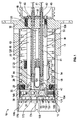
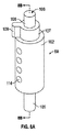
一実施形態では過酷な環境用のコネクタは、図1に示すプラグユニット10と、図2に示すレセプタクルユニット12と、を備え、これらのユニットが相互接続して、図3に示す一体型の円筒形コネクタが形成される。この実施形態におけるコネクタは、Cairnsの米国特許第6,017,227号において説明されるローリングシールコネクタと共通するいくつかの要素を有する。なお同特許の内容は参照することにより本明細書に援用される。一方、この実施形態におけるコネクタは変更されたシールアクチュエータ機構を有し、変更されたシールアクチュエータ機構は、レセプタクルユニット12におけるローリングシール88の動作を支援するために図6〜図13Gに示すアクチュエータ支援装置200および変更されたシールアクスルを備える他にも、変更されたアクスル装着ボア、変更されたレセプタクルマニホールドブロック、および変更されたシールアクチュエータも備える。なおこれらについては以下でより詳細に説明する。上記の図面では、ローリングシール、アクスル、アクチュエータロッド、およびアクチュエータ支援装置200を装着または受容するよう構成されたマニホールドブロックの一実施形態が図示されが、他の装着構成が代替的な実施形態において使用され得ることが理解されるであろう。   In one embodiment, the connector for a harsh environment includes a plug unit 10 shown in FIG. 1 and a receptacle unit 12 shown in FIG. 2, which are interconnected to form an integral cylinder shown in FIG. A shaped connector is formed. The connector in this embodiment has several elements in common with the rolling seal connector described in Cairns US Pat. No. 6,017,227. The contents of this patent are incorporated herein by reference. On the other hand, the connector in this embodiment has a modified seal actuator mechanism, and the modified seal actuator mechanism is shown in FIGS. 6 to 13G to support the operation of the rolling seal 88 in the receptacle unit 12. In addition to 200 and a modified seal axle, it also includes a modified axle mounting bore, a modified receptacle manifold block, and a modified seal actuator. These will be described in more detail below. In the above drawings, one embodiment of a manifold block configured to mount or receive a rolling seal, axle, actuator rod, and actuator assist device 200 is shown, but other mounting configurations are used in alternative embodiments. It will be understood that this can be done.

プラグユニット10は、シールされた後端部壁16と開放された前方端部18とを有する剛性物質製の外側円筒形外殻14を備える。剛性物質から製造されるプラグ接点マニホールドまたは前端部分20が、プラグチャンバ22において摺動可能に装着され、図1に示す前方位置へと付勢バネ24により付勢または事前負荷が与えられている。マニホールド20から外向きに突出するキーピン25が、マニホールド20が軸方向に動くことを可能にする一方でマニホールド20の回転を防止するために、外殻14の内側壁部上の軸方向に延びるキー溝またはスロット26に延びる。   The plug unit 10 includes an outer cylindrical outer shell 14 made of a rigid material having a sealed rear end wall 16 and an open front end 18. A plug contact manifold or front end portion 20 made from a rigid material is slidably mounted in the plug chamber 22 and is biased or preloaded by a biasing spring 24 to the forward position shown in FIG. A key pin 25 projecting outward from the manifold 20 is an axially extending key on the inner wall of the outer shell 14 to prevent the manifold 20 from rotating while allowing the manifold 20 to move axially. Extends into a groove or slot 26.

プラグマニホールドは、マニホールドの後端部から前方端部に延びる一連の平行な貫通ボアまたは通路28を有する。想定される接続の個数に依存してより少数またはより多数の接続が形成され得るが、ボアの個数は想定される接続(この場合では8個)の個数に依存する。図5に示すように、全ボアのうちの4つのボアがマニホールドブロック20の一方の半体に一直線状に配置され、他方の4つのボアはマニホールドの他方の半体に一直線状に配置されている。これらのボアは、マニホールドの正面に配置された1対の平行な部分円筒形凹陥部またはローリングシール座部30において終端する。なおここでは、4つのボアが一方の凹陥部において終端し、残りの4つのボアが他方の凹陥部において終端している。1対のローリングシール装置32がそれぞれの凹陥部30において回転可能に装着されている。   The plug manifold has a series of parallel through bores or passages 28 extending from the rear end of the manifold to the front end. Depending on the number of connections assumed, fewer or more connections may be formed, but the number of bores depends on the number of connections assumed (8 in this case). As shown in FIG. 5, four of the bores are arranged in a straight line on one half of the manifold block 20, and the other four bores are arranged in a straight line on the other half of the manifold. Yes. These bores terminate in a pair of parallel partial cylindrical recesses or rolling seal seats 30 located in front of the manifold. Here, four bores terminate in one recess and the remaining four bores terminate in the other recess. A pair of rolling seal devices 32 are rotatably mounted at each recess 30.

外殻端部壁16における一連の貫通ボア38のそれぞれが、マニホールド貫通ボア28のうちのそれぞれの貫通ボアと位置合わせされている。接点チャンバを画成する一連の導線ハウジング39および光ファイバハウジング40がそれぞれの位置合わせされたボア38および28を通って突出する。光ファイバ43は光ファイバハウジング40のボアを通り、アライメントフェルール44へと終端する。フェルール44はそれぞれの管状ハウジング40の端部における座部に固定される。導線またはワイヤ41は、電気ハウジング39のうちのそれぞれのハウジングを通って突出し、電気接点ピン42で終端する。ハウジング39およびハウジング40のうちのそれぞれのハウジングはOリングシール45を介して、端部壁16におけるそれぞれのボア38にシールされる。バッキングプレート47が装着ネジ48を介して後端部壁およびハウジング38および40の上方で固定され、この組み立てによりプラグユニットの終端端部において不浸透性の高圧バリアが形成される。ゴム製応力軽減部材またはブーツ49が、それぞれのハウジング39,40の突出端部と、プレート47の外側上の電気または光リード線のポートと、の上方で固定される。   Each of the series of through bores 38 in the outer shell end wall 16 is aligned with a respective through bore in the manifold through bore 28. A series of conductor housings 39 and fiber optic housings 40 defining contact chambers project through respective aligned bores 38 and 28. The optical fiber 43 passes through the bore of the optical fiber housing 40 and terminates in the alignment ferrule 44. The ferrule 44 is fixed to the seat at the end of each tubular housing 40. A lead or wire 41 projects through each of the electrical housings 39 and terminates at an electrical contact pin 42. Each of the housing 39 and the housing 40 is sealed to a respective bore 38 in the end wall 16 via an O-ring seal 45. A backing plate 47 is secured over the rear end wall and the housings 38 and 40 via mounting screws 48, and this assembly forms an impermeable high pressure barrier at the terminal end of the plug unit. A rubber stress relief member or boot 49 is secured above the protruding end of each housing 39, 40 and the electrical or optical lead port on the outside of the plate 47.

誘電性流体が、ボア28のうちのそれぞれのボアの前方端部を充填する。柔軟な内袋57および58は、必要に応じて内向きまたは外向きに曲がることにより、シールユニットの内側の流体と外側の流体との間で、圧力補償を提供する。   A dielectric fluid fills the forward end of each of the bores 28. Flexible inner bags 57 and 58 provide pressure compensation between the fluid inside and outside the seal unit by bending inward or outward as required.

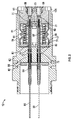
嵌合するレセプタクルユニット12も剛性の外側殻体61を有する。外側殻体61は終端または後端部壁62と、前方端部から内向きに突出する円筒形ボア64と、を有する。剛性物質製のレセプタクルマニホールドブロックまたは前端部分65が好適な保持ネジ(図示せず)を介して外殻61におけるボア65に固定され、それによりブロック65の後端部と端部壁62との間にチャンバ67が残ることとなる。なおチャンバ67はベントポート68を介してレセプタクルユニットの外部と連通する。   The receptacle unit 12 to be fitted also has a rigid outer shell 61. The outer shell 61 has a terminal or rear end wall 62 and a cylindrical bore 64 projecting inwardly from the front end. A receptacle manifold block or front end portion 65 made of rigid material is secured to the bore 65 in the outer shell 61 via a suitable retaining screw (not shown), so that between the rear end of the block 65 and the end wall 62. Thus, the chamber 67 remains. The chamber 67 communicates with the outside of the receptacle unit via a vent port 68.

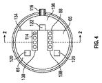
一連の貫通ボアまたは通路70がマニホールドブロック65を通って延び、ブロック65の前方端部における1対の部分円筒形座部または凹陥部73において終端する。ローリングシール装置88が座部73のうちのそれぞれの座部において回転可能に装着され、それにより図2に示す閉位置においてボア70の開放された前方端部がシールされる。貫通ボアの個数は上述のように想定される接続の個数に対応する。この場合においては、4つの平行ボアが、図2に見られるようにマニホールドの一方の半体に、図4に最もわかりやすく図示されるように他方の半体に、提供される。位置合わせされたボア72が後端部壁62において提供され、電気および/または光用の管状ハウジングまたはガイドチューブ74が、図2に示すように、ボア72を通り、位置合わせされたボア70へと、突出する。   A series of through bores or passages 70 extend through the manifold block 65 and terminate in a pair of partial cylindrical seats or recesses 73 at the forward end of the block 65. A rolling seal device 88 is rotatably mounted on each of the seats 73 so that the open front end of the bore 70 is sealed in the closed position shown in FIG. The number of through bores corresponds to the number of connections assumed as described above. In this case, four parallel bores are provided on one half of the manifold as seen in FIG. 2 and on the other half as best seen in FIG. An aligned bore 72 is provided in the rear end wall 62 and an electrical and / or optical tubular housing or guide tube 74 passes through the bore 72 and into the aligned bore 70 as shown in FIG. And protruding.

光ファイバ80が管状ハウジング74のボアを通り、アライメントフェルール81へと終端する。アライメントフェルール81はそれぞれの管状ハウジング74の端部における座部に固定される。光ファイバをアライメントフェルールに接続することは標準的なエポキシ研磨技術を使用して行われる。レセプタクル外殻の後端部は、ファイバ80に好適に接続されている光ファイバを担持する同軸光ケーブルの端部に当該後端部を接続するために、好適には、螺刻されるか、または他の固定装置が提供される。図2では光ファイバのみが図示されているが、ハイブリッド型コネクタでは、導線が、管状ハウジングの全部または一部のボアを通り、嵌合するプラグユニット10(図1参照)の電気接点42を受容するための電気ソケットにおいて終端する。環状のモリソンシール82が、端部壁をシールするために、それぞれの管状ハウジング74とそれぞれの後端部壁ボア72との間に提供される。   The optical fiber 80 passes through the bore of the tubular housing 74 and terminates in the alignment ferrule 81. The alignment ferrule 81 is fixed to the seat at the end of each tubular housing 74. Connecting the optical fiber to the alignment ferrule is done using standard epoxy polishing techniques. The rear end of the receptacle outer shell is preferably threaded to connect the rear end to the end of a coaxial optical cable carrying an optical fiber that is preferably connected to the fiber 80, or Other fixation devices are provided. Although only the optical fiber is shown in FIG. 2, in the hybrid type connector, the conductive wire passes through all or part of the bore of the tubular housing and receives the electrical contact 42 of the mating plug unit 10 (see FIG. 1). Terminate in the electrical socket to do. An annular Morrison seal 82 is provided between each tubular housing 74 and each rear end wall bore 72 to seal the end walls.

バッキングプレート83が装着ネジを介して後端部壁およびハウジング74の上方で固定され、この組み立てによりレセプタクルユニットの終端端部において不浸透性の高圧バリアが形成される。ボア72のカウンタボア部分にインストールされたバネ85はバッキングプレート83により定位置に保持され、電気ソケットおよび光フェルールを外向きに付勢する。応力軽減部材またはブーツ89が、バッキングプレート83の外側の電気および光リード線の突出部分端部の上方でシールされる。   A backing plate 83 is secured above the rear end wall and housing 74 via mounting screws, and this assembly forms an impermeable high pressure barrier at the terminal end of the receptacle unit. The spring 85 installed in the counter bore portion of the bore 72 is held in place by the backing plate 83 and biases the electrical socket and the optical ferrule outward. A stress relief member or boot 89 is sealed above the protruding portion end of the electrical and optical leads outside the backing plate 83.

圧力補償内袋98が、チャンバ67における接点ガイドチューブまたはハウジング74の全部を包囲し、後端部壁62とマニホールドブロック65との間で延び、それにより、図2に示すように誘電性の光学的に透明な流体で充填されている内部接点チャンバ69が形成される。付勢バネ97は、コネクタ外殻の後方部分62の近位の内側壁部に対して内袋の後端部を堅く付勢するよう、内袋の反対端部間で作用する。   A pressure compensating inner bag 98 surrounds the entire contact guide tube or housing 74 in the chamber 67 and extends between the rear end wall 62 and the manifold block 65, thereby providing a dielectric optical as shown in FIG. An internal contact chamber 69 is formed that is filled with a transparent fluid. The biasing spring 97 acts between the opposite ends of the inner bag so as to firmly bias the rear end of the inner bag against the proximal inner wall of the rear portion 62 of the connector shell.

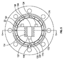
プラグユニットおよびレセプタクルユニットか図3に示すように嵌合されると、プラグマニホールドブロックが内向きに付勢される一方でローリングシールは開位置へと回転される。その結果、プラグ接点要素は、対応するレセプタクル接点要素に係合するために、開放されたプラグシールおよび位置合わせされたレセプタクルシールを通って突出する。図4および図5では、それぞれプラグユニットおよびレセプタクルユニットの嵌合端部表面が図示される。ここではローリングシールポート114は図3の開位置にある。プラグ外殻は、その端部表面から延びる軸方向キー溝118を有する一方でレセプタクルは、キー溝において係合するアライメントキー119を、これらのパーツが確実に互いに対して正確に方向付けられるよう、有する。キーおよびキー溝は、一緒に接続される際の、ポート間の相対的回転も防止する。正方形断面の2つのアクチュエータロッドポートまたは通路120がローリングシールアセンブリの一方の端部上でマニホールドブロック65の端部表面を通って内向きに突出する一方で、正方形断面の第3ポートまたは通路122が2つのローリングシール間の位置においてシールアセンブリの反対側面上で内向きに延びる。プラグユニットおよびレセプタクルユニットが一緒に接続されたときに通路124がポートまたは通路120と位置合わせされる一方で、通路125がポートまたは通路122と位置合わせされるよう、対応する通路124,125がプラグマニホールドブロックの嵌合端部表面上の同等の場所に提供される。通路124,125はプラグマニホールド本体の全体に延びる。図1にもっともよく図示されているように、1対のアクチュエータロッド126がプラグ外殻の基部または端部壁16に固定され、アクチュエータロッド126は、それぞれの通路124を通って摺動可能に延び、対応する正方形断面を有する。第3のアクチュエータロッド128(図7により詳細に示す)が端部壁16の一方の端部において固定され、ローリングシール32間で通路125を通って摺動可能に延び、通路125に対応する正方形断面を有する。   When the plug unit and receptacle unit are mated as shown in FIG. 3, the plug manifold block is biased inward while the rolling seal is rotated to the open position. As a result, the plug contact element projects through the open plug seal and the aligned receptacle seal to engage the corresponding receptacle contact element. 4 and 5 illustrate the mating end surfaces of the plug unit and receptacle unit, respectively. Here, the rolling seal port 114 is in the open position of FIG. The plug shell has an axial keyway 118 extending from its end surface, while the receptacle allows the alignment key 119 that engages in the keyway to be accurately oriented relative to each other. Have. The key and keyway also prevent relative rotation between the ports when connected together. Two actuator rod ports or passages 120 with a square cross section project inward through the end surface of the manifold block 65 on one end of the rolling seal assembly, while a third port or passage 122 with a square cross section is formed. Extends inwardly on the opposite side of the seal assembly at a location between the two rolling seals. Corresponding passages 124, 125 are plugged so that passage 124 is aligned with port or passage 120 while plug 125 and receptacle unit are connected together, while passage 125 is aligned with port or passage 122. Provided at an equivalent location on the mating end surface of the manifold block. The passages 124 and 125 extend throughout the plug manifold body. As best illustrated in FIG. 1, a pair of actuator rods 126 are secured to the base or end wall 16 of the plug shell and the actuator rods 126 slidably extend through respective passages 124. , With a corresponding square cross section. A third actuator rod 128 (shown in more detail in FIG. 7) is secured at one end of the end wall 16 and extends slidably through the passage 125 between the rolling seals 32 and corresponds to a square corresponding to the passage 125. It has a cross section.

マニホールドブロック20および65のうちのそれぞれのマニホールドブロックは、それぞれのマニホールドブロックの前端部における切り抜き部分は別にして、一体的に形成される。この切り抜き部分は、それぞれのローリングシールが装着されている部分円筒形の座部または凹陥部30,74(図1および図2参照)のうちのそれぞれの座部または凹陥部の一方の端部と交差する弦134(図4および図5参照)を有する。図4、図5、および図10において見られるように、対応する扇形部分136は、ローリングシールがそれぞれプラグマニホールドブロックおよびレセプタクルマニホールドブロックの前端部における2つの凹陥部30または73に設置された後に、切り抜き部分に嵌まるよう設計されている。   The manifold blocks of the manifold blocks 20 and 65 are integrally formed apart from the cutout portion at the front end of each manifold block. The cut-out portion includes one end of each of the seats or recesses of the partially cylindrical seats or recesses 30 and 74 (see FIGS. 1 and 2) to which the respective rolling seals are attached. It has intersecting strings 134 (see FIGS. 4 and 5). As can be seen in FIGS. 4, 5 and 10, the corresponding fan-shaped portion 136 is formed after the rolling seal is installed in the two recesses 30 or 73 at the front end of the plug manifold block and the receptacle manifold block, respectively. Designed to fit into cutout.

円筒形凹陥部またはローリングシール座部30はレセプタクルマニホールドブロックの端部表面におけるスロット形状の開口部137(図5参照)を有し、円筒形凹陥部またはローリングシール座部73はプラグマニホールドブロックの端部表面におけるスロット形状の開口部138(図4参照)を有する。レセプタクルの本体65におけるそれぞれの凹陥部の一方の端部におけるカウンタボアは、それぞれのローリングシールの端部部分またはアクスル105を受容するよう設計され、パーツ136の嵌合端部表面における開放された端部を有する1対のステップ加工された直径のボアまたはチャンバ(図面においては見えない)は、ローリングシールのうちのそれぞれのローリングシールの反対端部部分106を受容するよう設計される。プラグマニホールドにおけるローリングシールは反対方向に向けられており、それぞれの端部部分またはアクスル106はパーツ136におけるカウンタボアにおいて受容され、反対端部部分106は本体20のカウンタボアにおいて受容される。   The cylindrical recess or rolling seal seat 30 has a slot-shaped opening 137 (see FIG. 5) at the end surface of the receptacle manifold block, and the cylindrical recess or rolling seal seat 73 is the end of the plug manifold block. A slot-shaped opening 138 (see FIG. 4) is provided on the surface of the part. The counterbore at one end of each recess in the receptacle body 65 is designed to receive the end portion or axle 105 of the respective rolling seal and is open at the mating end surface of the part 136. A pair of stepped diameter bores or chambers having portions (not visible in the drawings) are designed to receive the opposite end portion 106 of each rolling seal of the rolling seals. The rolling seals in the plug manifold are oriented in opposite directions, with each end portion or axle 106 received in a counter bore in part 136 and the opposite end portion 106 received in a counter bore in body 20.

レセプタクルユニットのローリングシール88が図6〜図8においてより詳細に図示される。図6〜図8では、ローリングシール88はレセプタクルユニットの他の部分から分離して示されている。一実施形態では、それぞれのレセプタクルローリングシールは剛性コアまたはアクスルを備え、この剛性コアまたはアクスル上に、弾性状のローラまたはスリーブ102が成型されるかまたは別様に固定される。アクスルは金属製または硬質プラスチック製であって、中心部分104を有し、中心部分104上にスリーブ102が成型され、第1アクスル端部部分105および第2アクスル端部部分106がスリーブ102の反対端部から突出する。   The receptacle unit rolling seal 88 is illustrated in more detail in FIGS. 6-8, the rolling seal 88 is shown separate from the other parts of the receptacle unit. In one embodiment, each receptacle rolling seal includes a rigid core or axle on which an elastic roller or sleeve 102 is molded or otherwise secured. The axle is made of metal or hard plastic and has a central portion 104 on which a sleeve 102 is molded, and a first axle end portion 105 and a second axle end portion 106 are opposite the sleeve 102. Projects from the end.

端部部分106は第1の、直径がより大きい部分107と、直径がより小さい端部部分108と、を有する。径方向タブまたは歯状物109が第1部分107から突出する。弾性状のスリーブ102は図8Aおよび図8Bに示すように貫通ボア114を有する。レセプタクルシールにおいて、第1アクスル端部部分105は拡張され、アクチュエータ支援装置またはアクチュエータ付勢装置200が、図6および図9〜図11において見られるように、端部部分105の上方に装着される。この実施形態では、付勢装置200はトーションバネ202を備えるが、他種類のバネまたは他の付勢装置が他の実施形態では使用され得る。この実施形態におけるプラグユニットではアクチュエータ支援装置が提供されていないため、プラグシール32は、アクスル端部部分105の拡張された部分を除き、レセプタクルシールと同様である。代替的な実施形態において必要であるならば、プラグシール32は、アクチュエータ付勢装置の装着がプラグシールのアクスルシャフト上で、ならびに、レセプタクルアクチュエータシャフト上で、可能となるよう変更されてもよい。   The end portion 106 has a first larger diameter portion 107 and a smaller diameter end portion 108. A radial tab or tooth 109 protrudes from the first portion 107. The elastic sleeve 102 has a through bore 114 as shown in FIGS. 8A and 8B. In the receptacle seal, the first axle end portion 105 is expanded and the actuator assisting device or actuator biasing device 200 is mounted above the end portion 105 as seen in FIGS. 6 and 9-11. . In this embodiment, the biasing device 200 includes a torsion spring 202, although other types of springs or other biasing devices may be used in other embodiments. Since the actuator unit is not provided in the plug unit in this embodiment, the plug seal 32 is similar to the receptacle seal except for an expanded portion of the axle end portion 105. If required in alternative embodiments, the plug seal 32 may be modified to allow attachment of the actuator biasing device on the plug seal axle shaft as well as on the receptacle actuator shaft.

それぞれのローリングシール88の本体は、図4、図10、および図11に最もわかりやすく図示されているように、レセプタクルマニホールドブロック65の正面における合致する座部73に回転可能に係合される一方で、アクスル端部部分105,106はそれぞれの凹陥部73の反対端部における対応するカウンタボアにおいて回転可能に装着される。アクチュエータタブ109を担持するアクスル端部部分106を受容するマニホールドブロックの扇形部分136のみが、反対のアスクル部分105上のアクチュエータ支援トーションバネ202を明らかにするために、図6において図示されている。アクスル端部部分106は、扇形部分136における対応する座部またはカウンタボアに回転可能に装着され、カウンタボアは、開口部またはスロット204を介して、マニホールドブロックの外側端部を通って内向きに延びるボートまたは通路122の反対側面と連通する(図6および図10参照)。径方向タブ109は、図2、図6、および図10に最もわかりやすく示されているように、通路122の反対側面へと突出する。   The body of each rolling seal 88 is rotatably engaged with a mating seat 73 at the front of the receptacle manifold block 65, as best shown in FIGS. 4, 10, and 11. Thus, the axle end portions 105, 106 are rotatably mounted in corresponding counter bores at the opposite ends of the respective recessed portions 73. Only the fan-shaped portion 136 of the manifold block that receives the axle end portion 106 carrying the actuator tab 109 is shown in FIG. 6 to reveal the actuator-assisted torsion spring 202 on the opposite axle portion 105. Axle end portion 106 is rotatably mounted to a corresponding seat or counterbore in sector portion 136, and the counterbore is directed inwardly through the outer end of the manifold block through an opening or slot 204. It communicates with the opposite side of the extending boat or passage 122 (see FIGS. 6 and 10). The radial tab 109 protrudes to the opposite side of the passage 122 as best shown in FIGS. 2, 6, and 10.

図9および図10においてもっともよく図示されているようにアクスル端部部分105は、シール座部73の反対端部から延びるカウンタボア205に延びる。カウンタボア205は、製造の際にトーションバネ202をボア端部部分105に装着することを可能にするためにマニホールドブロックの外側円筒形端部表面を通してアクセス可能であり、組み立ての後にシール目的のために蓋で覆われ得る。図6、図10、および図12Aで示されるように、それぞれのバネの一方の端部208はボアまたは座部に固定されて、拡張された端部アクスル部分105へと径方向で内向きに延びる一方で、反対の端部210は図6、図9、図11に最もわかりやすく図示されているように、径方向で外向きに曲げられてボアまたは座部212に固定され、マニホールドカウンタボア206から固定されたマニホールドブロック65へと内向きに延びる。ボアまたはバネ座部212は必ずしも貫通孔ではなく、一実施形態では、マニホールドブロックに0.5インチほど延びる。貫通孔212は、バネが設置された後、エポキシ材料その他でシールされ得る。   As best shown in FIGS. 9 and 10, the axle end portion 105 extends into a counterbore 205 that extends from the opposite end of the seal seat 73. The counterbore 205 is accessible through the outer cylindrical end surface of the manifold block to allow the torsion spring 202 to be attached to the bore end portion 105 during manufacture and for assembly purposes after assembly. Can be covered with a lid. As shown in FIGS. 6, 10, and 12A, one end 208 of each spring is secured to the bore or seat and is radially inward to the expanded end axle portion 105. While extending, the opposite end 210 is bent radially outwardly and secured to the bore or seat 212, as best shown in FIGS. 6, 9, and 11, to provide a manifold counterbore. Extending inwardly from 206 to a fixed manifold block 65. The bore or spring seat 212 is not necessarily a through hole, and in one embodiment extends about 0.5 inches into the manifold block. The through-hole 212 can be sealed with an epoxy material or the like after the spring is installed.

凹陥部30および73はそれぞれの弾性状スリーブ102よりもわずかに直径が小さい。ローリングシールは、パーツ36を受容するマニホールド本体の端部表面134における開放端部を介して凹陥部30または凹陥部73へと滑り込ませられ、それによりシャフトまたはアクスルの突出する端部部分105または106はそれぞれの凹陥部30または73の反対端部におけるカウンタボアに延びる。レセプタクルローリングシール88のアクスル端部部分106はこの時点で端部表面134から突出している。次に付勢バネ202が、レセプタクルマニホールドブロックの拡張されたボア部分206における端部部分105のパーツの上方で固定され、ボアはシール目的のために蓋で覆われ得る。次に、アクスル受容ボア(図示せず)がローリングシールの突出する端部部分106の上方で係合し、ローリングシール88をキャプチャするよう、扇形部分136がマニホールドブロックの前端部における切り抜き領域へと挿入される。パーツ136は任意の好適な様式でマニホールドブロックの残りの部分に固定され得る。   The recesses 30 and 73 are slightly smaller in diameter than the respective elastic sleeves 102. The rolling seal is slid into the recess 30 or recess 73 through the open end at the end surface 134 of the manifold body that receives the part 36, thereby projecting the end portion 105 or 106 of the shaft or axle. Extends to the counterbore at the opposite end of each recess 30 or 73. The axle end portion 106 of the receptacle rolling seal 88 now protrudes from the end surface 134. The biasing spring 202 is then secured over the part of the end portion 105 in the expanded bore portion 206 of the receptacle manifold block and the bore can be covered with a lid for sealing purposes. Next, the fan-shaped portion 136 is moved to a cut-out area at the front end of the manifold block so that an axle receiving bore (not shown) engages above the protruding end portion 106 of the rolling seal and captures the rolling seal 88. Inserted. Part 136 may be secured to the remainder of the manifold block in any suitable manner.

この実施形態ではアクチュエータ支援装置またはバネを含まないプラグユニットの場合には、ローリングシールは主要マニホールドブロックにおける凹陥部またはシール30へ反対方向に挿入される。ここでは、端部部分105は主要マニホールドブロックにおけるカウンタボア上に係合し、アクチュエータタブを有する端部部分106は正面134から突出して弓形状部分136における受容ボアまたは座部に係合する。本発明の一実施形態では、プラグユニットのマニホールドブロック20の外側円筒形表面およびパーツ136の部分円筒形外側表面は合致するネジ山を有する。螺刻されたコレットスリーブ145がパーツ136のプラグマニホールド20の前端部上でネジ留めされ、これらのパーツが一緒に固定される。レセプタクルマニホールドブロックでは、パーツ136は外側殻体61により、およびマニホールドブロックからパーツ136へと横切って延びるピンまたはバネ190により、定位置に保持される。   In this embodiment, in the case of an actuator support or a plug unit that does not include a spring, the rolling seal is inserted in the opposite direction into the recess or seal 30 in the main manifold block. Here, end portion 105 engages on a counterbore in the main manifold block, and end portion 106 with an actuator tab protrudes from front 134 and engages a receiving bore or seat in arcuate portion 136. In one embodiment of the present invention, the outer cylindrical surface of the plug unit manifold block 20 and the partial cylindrical outer surface of the part 136 have matching threads. A threaded collet sleeve 145 is screwed onto the front end of the plug manifold 20 of part 136, and these parts are secured together. In the receptacle manifold block, the part 136 is held in place by the outer shell 61 and by a pin or spring 190 that extends across from the manifold block to the part 136.

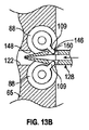
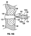
ローリングシール88をレセプタクルマニホールドの凹陥部73に設置することは、上述のように、ローリングシール88がプラグユニットにおけるシールに対して反対方向に向けられているという点、および付勢バネまたはアクチュエータ支援装置202がレセプタクルローリングシール88の拡張されたアクスル部分上に設置されているという点を除き、プラグマニホールドにおけるローリングシール32に対する設置と同一である。プラグユニットおよびレセプタクルユニットが一緒に接続される際のローリングシールアセンブリの動作は、図13A〜図13Gを参照するとよりよく理解され得る。これらのユニットが分離されて非接続状態にあるときは、それぞれのローリングシールは図1、図2、図6、および図13Aに示すように閉位置にある。この位置では、貫通ポート114はこれらのユニットの端部表面に対して平行に延び、光ファイバおよび導線を担持するボアは閉止される。   Placing the rolling seal 88 in the recess 73 of the receptacle manifold is that, as described above, the rolling seal 88 is oriented in the opposite direction relative to the seal in the plug unit, and the biasing spring or actuator support device The installation is the same as for the rolling seal 32 in the plug manifold, except that 202 is installed on the expanded axle portion of the receptacle rolling seal 88. The operation of the rolling seal assembly when the plug unit and the receptacle unit are connected together may be better understood with reference to FIGS. 13A-13G. When these units are separated and disconnected, the respective rolling seals are in the closed position as shown in FIGS. 1, 2, 6, and 13A. In this position, the through-port 114 extends parallel to the end surfaces of these units and the bore carrying the optical fiber and the conductor is closed.

図1および図2の嵌合が解放された、またはシール閉止状態では、ローリングシールの弾性状部分は、それぞれプラグマニホールドおよびレセプタクルマニホールドの端部表面における位置合わせされた開口部またはスロット137,138を通って外向きに突出する。レセプタクルユニットシール88が閉止されているとき、スロット204を介して通路122へと突出するアクスル部分106のタブ109の端部(図8Aおよび図8B)は、ローリングシール88のうちの一方に対して図6に示すように、タブまたは歯状物109がそれぞれのスロット204の前方端部に対して係合している状態で配置される。同様に図1に示すように、プラグユニットシール32が閉止されているとき、それぞれのプラグユニットローリングシールの拡大された端部部分106も同様の凹陥領域またはチャンバ140に配置される。しかしこの場合では、タブまたは歯状物109はチャンバ140と通路124との間で通路の後端部壁149に係合する。これは止め具として作用する。   When the mating of FIGS. 1 and 2 is released or the seal is closed, the resilient portion of the rolling seal has aligned openings or slots 137, 138 at the end surfaces of the plug manifold and receptacle manifold, respectively. Protrudes outward through. When the receptacle unit seal 88 is closed, the end of the tab 109 (FIGS. 8A and 8B) of the axle portion 106 that projects into the passage 122 through the slot 204 is against one of the rolling seals 88. As shown in FIG. 6, tabs or teeth 109 are arranged in engagement with the front ends of the respective slots 204. Similarly, as shown in FIG. 1, when the plug unit seal 32 is closed, the enlarged end portion 106 of each plug unit rolling seal is also placed in a similar recessed area or chamber 140. In this case, however, the tab or tooth 109 engages the rear end wall 149 of the passage between the chamber 140 and the passage 124. This acts as a stop.

プラグローリングシールを作動させる1対のアクチュエータロッド126は同様であって、それぞれ長尺ロッドを備える。この長尺ロッドは、その後端部においては固体の正方形断面であり、その全長の残りの部分に沿っては略L字断面である。それぞれのロッドの前方端部における端部壁152は、図1に示すようにシールが閉止されているときには、プラグマニホールドブロックの端部表面と同一平面状となる。タブまたはフランジ154は端部壁152から内向きに離間した位置にあり、図1に示すようにローリングシールの反対側面上に配置される。2つのロッド126はわずかにバネのような弾力性示し、タブ154が互いに向かって内向きに対向し、ロッドがわずかに外向きに湾曲するよう、プラグ後端部壁16に装着される。   The pair of actuator rods 126 that actuate the plug rolling seal is similar and each comprises a long rod. The long rod has a solid square cross section at the rear end and a substantially L-shaped cross section along the remaining portion of the full length. When the seal is closed as shown in FIG. 1, the end wall 152 at the front end of each rod is flush with the end surface of the plug manifold block. The tab or flange 154 is inwardly spaced from the end wall 152 and is located on the opposite side of the rolling seal as shown in FIG. The two rods 126 are slightly spring-like elastic and are mounted on the plug rear end wall 16 so that the tabs 154 face inwardly toward each other and the rods are curved slightly outward.

両方のレセプタクルローリングシール88を作動させる単一または中心のアクチュエータロッド128は後方端部壁16からプラグユニットにおける長方形通路またはポート125を通って延び、ロッド128の一部が図1で見られる。図7に最もわかりやすく図示されているように、中心アクチュエータロッド128の前方端部部分は1対の別個の枝部158を有し、係る枝部158のそれぞれは、図13A〜図13Gに示すように、レセプタクルローリングシールに係合し、それぞれ閉位置から開位置へと、および開位置から閉位置へと、レセプタクルローリングシールを回転させるよう設計された、ノッチ160のそれぞれの端部において作動構造160Aおよび160Bを有するアクチュエータノッチ160を有する。枝部158はわずかに弾性または「バネのような弾力性」を示す。枝部158k前方端部170は、ロッド128がテーパ状の先端部を有するよう、互いに向かって内向きに傾けられている。   A single or central actuator rod 128 that actuates both receptacle rolling seals 88 extends from the rear end wall 16 through a rectangular passage or port 125 in the plug unit, a portion of which is seen in FIG. As best shown in FIG. 7, the forward end portion of the central actuator rod 128 has a pair of separate branches 158, each of which is shown in FIGS. 13A-13G. The actuating structure at each end of the notch 160 is designed to engage the receptacle rolling seal and rotate the receptacle rolling seal from the closed position to the open position and from the open position to the closed position, respectively. It has an actuator notch 160 with 160A and 160B. The branches 158 are slightly elastic or “spring-like elastic”. The branch 158k front end 170 is inclined inward toward each other such that the rod 128 has a tapered tip.

上述のようにこの実施形態におけるプラグユニットおよびレセプタクルユニットを接続する前、ローリングシール32および88のうちのそれぞれのローリングシールは、図1および図2に最もわかりやすく図示されているように、プラグマニホールドおよびレセプタクルマニホールドの端部表面におけるそれぞれのスロット開口部137および138から部分的に外向きに突出している。これら2つのユニットが適切な相対的方向で近づけられるにつれて、アクチュエータロッド128を担持するプラグ外殻内の中心通路125はレセプタクルマニホールドのポートまたは通路122と位置合わせされる一方で、アクチュエータロッド126を担持する通路124はポートまたは通路120と位置合わせされる。   Prior to connecting the plug unit and receptacle unit in this embodiment as described above, each of the rolling seals 32 and 88 is plug manifold as shown most clearly in FIGS. And partially projecting outwardly from respective slot openings 137 and 138 at the end surface of the receptacle manifold. As these two units are brought together in the proper relative orientation, the central passage 125 in the plug shell carrying the actuator rod 128 is aligned with the port or passage 122 of the receptacle manifold while carrying the actuator rod 126. The passage 124 is aligned with the port or passage 120.

アクチュエータロッド126上のタブまたはフランジ154を備えるアクチュエータ構造は、図1に示すようにプラグユニットおよびレセプタクルユニットが接続される前に、それぞれのローリングシール32上のタブまたは歯状物109に係合する。プラグユニットおよびレセプタクルユニットが係合するように近づけられるにつれて、アクチュエータロッド128はレセプタクルマニホールド65におけるポート122と位置合わせされる。中心アクチュエータロッド128の前方端部が嵌合される前にはプラグマニホールド20の前方端部表面からわずかに出ているため、2つのマニホールドが対向するとき、中心アクチュエータロッド128の前方端部はレセプタクルマニホールドの位置合わせされたポート122へと突き出る。図13Aでは、2つのユニットが対向して係合する状態に最初に近づけられる際のレセプタクルマニホールドの端部表面に対するロッド128の位置が図示される。   The actuator structure comprising a tab or flange 154 on the actuator rod 126 engages a tab or tooth 109 on the respective rolling seal 32 before the plug unit and receptacle unit are connected as shown in FIG. . As the plug unit and receptacle unit are brought closer to engage, the actuator rod 128 is aligned with the port 122 in the receptacle manifold 65. Since the front end of the central actuator rod 128 slightly protrudes from the front end surface of the plug manifold 20 before the front end is fitted, when the two manifolds face each other, the front end of the central actuator rod 128 becomes the receptacle. Protrudes into the aligned port 122 of the manifold. In FIG. 13A, the position of the rod 128 relative to the end surface of the receptacle manifold when the two units are first brought close to engaging each other is illustrated.

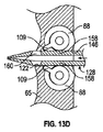
これらのコネクタユニットは嵌合動作の第1段階において一緒に押し付けられ、その段階ではプラグローリングシール32およびレセプタクルローリングシール88の突出する部分が平坦化され、これらのローリングシールの対向する表面間から水が効果的に除去され、プラグのローリングシールの表面がレセプタクルのローリングシールの表面に対してシールされる。この時点では、デブリが、対向するシールの表面間に囚われている場合がある。キー119がキー溝118に進入しつつコネクタユニットがさらに一緒に押圧されると、プラグマニホールドが内向きに付勢されるにつれてプラグユニットのバネ24が圧縮し始める。同時にロッド126,128はポート124,125を通して外向きに突き出し、位置合わせされたポート120,122へと動く。このようにレセプタクルがプラグユニット外殻へと動き続けるにつれて、レセプタクルマニホールドブロックは、図13A〜13Gでロッド128に対して図示されるように、ロッド126,128により突き刺される。ロッド128がポート122に進入する(図13B参照)につれて、ノッチ160の作動表面160Aはそれぞれのローリングシールタブまたは歯状物109に接触する。ローリングシールタブまたは歯状物109は図6、図13A、および図13Bに示すようにポート122へと部分的に突き出している。図13Bではアクチュエータロッド128がポート122へと部分的に貫入する様子が示されている。ロッド128が図13Bの矢印の方向で内向きに進入を続けるにつれて、ノッチ160の端部表面160Aがタブ109に係合し、それにより2つのローリングシールは、図13Cに図示するように端部位置に到達するまで、それぞれの長手方向軸を中心にして反対方向に回転する。   These connector units are pressed together in the first stage of the mating operation, where the projecting portions of the plug rolling seal 32 and the receptacle rolling seal 88 are flattened and water is introduced between the opposing surfaces of these rolling seals. Is effectively removed and the surface of the plug rolling seal is sealed against the surface of the receptacle rolling seal. At this point, debris may be trapped between opposing seal surfaces. As the key 119 enters the keyway 118 and the connector unit is further pressed together, the plug unit spring 24 begins to compress as the plug manifold is biased inward. At the same time, rods 126 and 128 protrude outwardly through ports 124 and 125 and move to aligned ports 120 and 122. As the receptacle continues to move into the plug unit shell in this manner, the receptacle manifold block is pierced by the rods 126, 128, as illustrated for the rod 128 in FIGS. As the rod 128 enters the port 122 (see FIG. 13B), the working surface 160A of the notch 160 contacts the respective rolling seal tab or tooth 109. The rolling seal tab or tooth 109 partially protrudes into the port 122 as shown in FIGS. 6, 13A, and 13B. In FIG. 13B, the actuator rod 128 is shown partially penetrating into the port 122. As the rod 128 continues inward in the direction of the arrow in FIG. 13B, the end surface 160A of the notch 160 engages the tab 109, so that the two rolling seals end as shown in FIG. 13C. Rotate in the opposite direction about each longitudinal axis until a position is reached.

図13Cでは、それぞれのアクスル端部部分107のタブ109が通路または接続スロット204(図6に最もわかりやすく見られる)の反対端部に係合し、それによりさらなる回転が妨げられている最終位置が図示されている。この位置では、貫通ボア114が開位置へと回転し、図3でも示されているようにプラグローリングシール内の対応するボアと位置合わせされるよう、ローリングシールは90度回転している。このようにタブ109は、図6および図13Aにおけるようにタブ109が通路または接続スロット204の前方端部146に当接する閉位置と、図13Cにおけるようにピン109が接続スロット204の後方または内側端部148に当接する開位置と、の間でローリングシール88が回転することを可能にする。   In FIG. 13C, the final position where the tab 109 of each axle end portion 107 engages the opposite end of the passage or connection slot 204 (best seen in FIG. 6), thereby preventing further rotation. Is shown. In this position, the through-bore 114 is rotated to the open position and the rolling seal is rotated 90 degrees so that it is aligned with the corresponding bore in the plug rolling seal as also shown in FIG. Thus, tab 109 is in a closed position where tab 109 abuts the front end 146 of the passage or connection slot 204 as in FIGS. 6 and 13A, and pin 109 is behind or inward of connection slot 204 as in FIG. The rolling seal 88 is allowed to rotate between the open position abutting the end 148.

図12Aおよび図12Bに示すように、レセプタクルローリングシールおよびシャフト105が図12Aの閉位置と図12Bの開位置との間で90度回転するにつれて、シャフト105に固定されたトーションバネの下方端部208も、図12Aで示される位置から図12Bで示される端部位置へと、固定された上方端部210に対して回転する。このようにバネは開位置において負荷が与えられ、シールを閉位置に向かって戻すよう付勢する。以下でより詳細に説明するように、このことはプラグユニットおよびレセプタクルユニットの嵌合解放時にシールの閉止を支援する。   12A and 12B, the lower end of the torsion spring secured to the shaft 105 as the receptacle rolling seal and shaft 105 rotates 90 degrees between the closed position of FIG. 12A and the open position of FIG. 12B. 208 also rotates relative to the fixed upper end 210 from the position shown in FIG. 12A to the end position shown in FIG. 12B. Thus, the spring is loaded in the open position and biases the seal back toward the closed position. As will be explained in more detail below, this assists in closing the seal when the plug and receptacle units are unmated.

プラグマニホールドがプラグ外殻へと内向きに付勢され続けるにつれて、図13Dに示すようにローリングシールが完全に開放された後、アクチュエータロッド128はポート122へとさらに内向きに移動する。枝部158は、タブ109を無事通過するように内向きに圧縮され、タブ109を越えると直ちにバネのような弾力性により再び離れる。シールが開放され、ロッド128が図13Dの最内側の位置にあるとき、タブ109はアクチュエータロッド128の反対表面に係合し、これによりバネがシールをシール閉止方向に付勢することが防止される。   As the plug manifold continues to be biased inward into the plug shell, the actuator rod 128 moves further inward to the port 122 after the rolling seal is fully opened, as shown in FIG. 13D. The branch portion 158 is compressed inward so as to pass through the tab 109 safely, and immediately after the tab 109 is crossed, the branch portion 158 is separated again by spring-like elasticity. When the seal is opened and the rod 128 is in the innermost position of FIG. 13D, the tab 109 engages the opposite surface of the actuator rod 128, thereby preventing the spring from urging the seal in the seal closing direction. The

ロッド128がローリングシール88のより大きい端部部分においてレセプタクルユニットへと伸長する間、同時に、ロッド126もポート120への進入を開始する。その際、ロッド126は、プラグマニホールドがさらに外殻140へと内向きに押し続けられるにつれて、プラグマニホールドのチャンバまたは領域140を通って徐々に進行する。ロッド126はプラグマニホールド内のローリングシール32を作動させ、米国特許第6,017,227号でより詳細に説明されているように、ロッド128がレセプタクルマニホールド内のローリングシールを開放させるのと略同様に、ローリングシール32を開位置へと回転させる。なお同特許は上記で参照することにより本明細書に引用および援用される。   At the same time, the rod 126 begins to enter the port 120 while the rod 128 extends into the receptacle unit at the larger end portion of the rolling seal 88. In doing so, the rod 126 gradually progresses through the chamber or region 140 of the plug manifold as the plug manifold continues to be pushed inward further into the outer shell 140. The rod 126 activates the rolling seal 32 in the plug manifold and is substantially the same as the rod 128 opens the rolling seal in the receptacle manifold, as described in more detail in US Pat. No. 6,017,227. Then, the rolling seal 32 is rotated to the open position. This patent is incorporated herein by reference and referred to above.

ロッド126のアクチュエータ部分154と、ロッド128のアクチュエータ部分160と、の間の関係は、レセプタクルローリングシールおよびプラグローリングシールが同時に反対方向に作動されるような関係となっている。プラグユニットおよびレセプタクルユニットが、図1および図2の位置から、図3の位置(ここでは、プラグマニホールドが部分的に内向きに押し込まれている)に、移動するにつれて、ローリングシールはすべて、ボアがすべて開放されてレセプタクルユニットからプラグユニットへと接続されるよう、90度回転されている。ローリングシールの嵌合端部表面間に捕捉されているあらゆるデブリは、これらの表面が回転するにつれてシールの一方の側面へと外向きに、位置合わせされたボアの領域から離れる方向に、回転される傾向にある。   The relationship between the actuator portion 154 of the rod 126 and the actuator portion 160 of the rod 128 is such that the receptacle rolling seal and the plug rolling seal are simultaneously actuated in opposite directions. As the plug unit and receptacle unit move from the position of FIGS. 1 and 2 to the position of FIG. 3 (where the plug manifold is partially pushed inward), all rolling seals are Are rotated 90 degrees so that they are all open and connected from the receptacle unit to the plug unit. Any debris trapped between the mating end surfaces of the rolling seal is rotated outwardly to one side of the seal and away from the aligned bore area as these surfaces rotate. It tends to be.

嵌合シーケンスが図13Cに示す時点を越えて進行するにつれて、プラグマニホールドはさらに内向きに押され、プラグの電気用および光用の接点は、ローリングシール32およびローリングシール88の位置合わせされたポート114を貫通し、次第にレセプタクルの流体槽内の、それぞれレセプタクル内の電気ソケットおよび光フェルールの表面と接触することとなる。完全に係合されたコネクタが図3に図示されている。バネ24が圧縮され、レセプタクル外殻の拡大された直径の部分が最大限押し込まれて、プラグ外殻の端部リム18上に接している様子が見られ得る。ローリング端部シールを通過すると、プラグの管状接点ハウジング40はローリングシールの弾性状ボア114を拡張させ、それによりボアは管状接点ハウジングの外側表面を把持し、当該外側表面に対してシールする。二重シールがプラグおよびレセプタクルの両方に提供され、閉止された流体槽が端部シール内に捕らえられる。二重端部シールは電気コネクタならびに光コネクタに対して有利であると考えられる。   As the mating sequence proceeds beyond the point in time shown in FIG. 13C, the plug manifold is pushed further inward and the plug electrical and light contacts are aligned ports of the rolling seal 32 and rolling seal 88. 114 will gradually come into contact with the electrical socket and the surface of the optical ferrule in the receptacle, respectively, in the fluid reservoir of the receptacle. A fully engaged connector is illustrated in FIG. It can be seen that the spring 24 is compressed and the enlarged diameter portion of the receptacle shell is pushed in as much as possible to contact the end rim 18 of the plug shell. Upon passing the rolling end seal, the plug tubular contact housing 40 expands the rolling seal elastic bore 114 so that the bore grips and seals to the outer surface of the tubular contact housing. A double seal is provided on both the plug and the receptacle, and a closed fluid reservoir is trapped within the end seal. Double end seals are considered advantageous for electrical connectors as well as optical connectors.

コネクタユニットが嵌合されるのに伴い、プラグ接点要素およびレセプタクル接点要素またはフェルールの係合へと至るこれらのユニット間の相対的動きは、プラグおよびレセプタクルのオイルチャンバまたはオイル槽内の体積に変化を生じさせる。様々な温度変化および圧力変化に起因して生じ得る変化に加えて、これらの変化は、薄い膜で覆われた弾性状の調節板または内袋57および58を湾曲させ、それにより、係る体積変化に順応するために、係る調節板または内袋の形状を変化させる。これらの補償器はベントポート50および68を介して外側環境へと流体を逃がす。   As the connector unit is mated, the relative movement between these units leading to the engagement of the plug contact element and the receptacle contact element or ferrule changes to the volume in the oil chamber or oil reservoir of the plug and receptacle. Give rise to In addition to the changes that can occur due to various temperature and pressure changes, these changes cause the elastic adjustment plates or inner bags 57 and 58 covered with a thin membrane to bend, thereby causing such volume changes. In order to adapt to, the shape of the adjusting plate or the inner bag is changed. These compensators allow fluid to escape through vent ports 50 and 68 to the outside environment.

プラグマニホールド上のロッキングコレットまたはスリーブ145は、ローリングシールが開位置にあるときに端部表面をシール係合において保持し、シールが回転して閉位置まで戻されるまで端部表面の分離を防止するために、レセプタクルユニットの外側殻体61との解放可能なスナップロック係合を有する。複数の離間された弾力性フィンガ172が、コレットの前方端部における一連の内側に向けられたスロット172により提供される。コレットは開放された前方端部の近位において、内向きに突出する環状リブ175を有する。係る環状リブ175はフィンガ172を横切って延びる。レセプタクルユニットの外側殻体61は、対応する環状溝部176(図2)を有する。環状溝部176は、レセプタクルマニホールド65の前端部から、プラグマニホールド20の前方端部表面とリブ17との間の離間に等しい距離だけ、離間されている。   A locking collet or sleeve 145 on the plug manifold holds the end surface in seal engagement when the rolling seal is in the open position and prevents end surface separation until the seal is rotated back to the closed position. For this, it has a releasable snap lock engagement with the outer shell 61 of the receptacle unit. A plurality of spaced resilient fingers 172 are provided by a series of inwardly directed slots 172 at the forward end of the collet. The collet has an inwardly projecting annular rib 175 proximal to the open front end. Such an annular rib 175 extends across the finger 172. The outer shell 61 of the receptacle unit has a corresponding annular groove 176 (FIG. 2). The annular groove 176 is spaced from the front end of the receptacle manifold 65 by a distance equal to the distance between the front end surface of the plug manifold 20 and the rib 17.

プラグユニットの外側殻体14は、より大きい直径の外側端部部分178と、より小さい直径の部分179と、を有するボアを有する。部分178と、部分179と、は環状ステップまたは肩部180により隔てられている。プラグユニットおよびレセプタクルユニットの接続の前、プラグローリングシールが図1におけるように閉止されているとき、リブ175などのロッキングコレットはプラグ外殻ボアの直径がより大きい部分178に配置されている。レセプタクルユニットおよびプラグユニットが一緒に結合されるにつれて、バネ24の圧縮が開始される前にリブ175は溝部176にスナップ嵌合する。レセプタクルマニホールドがプラグマニホールドを押し戻し、ローリングシールが動き始めるとき、ロッキングリブ175は、プラグマニホールドがレセプタクルマニホールドおよび外殻と一緒にロックされるよう、ボアのより小さい直径の部分179へと押し戻される。   The outer shell 14 of the plug unit has a bore having a larger diameter outer end portion 178 and a smaller diameter portion 179. Portion 178 and portion 179 are separated by an annular step or shoulder 180. Prior to connection of the plug unit and the receptacle unit, when the plug rolling seal is closed as in FIG. 1, a locking collet such as rib 175 is located in the portion 178 where the diameter of the plug shell bore is larger. As the receptacle unit and plug unit are coupled together, the rib 175 snaps into the groove 176 before the compression of the spring 24 begins. When the receptacle manifold pushes back the plug manifold and the rolling seal begins to move, the locking rib 175 is pushed back into the smaller diameter portion 179 of the bore so that the plug manifold is locked together with the receptacle manifold and outer shell.

これらのユニットが分離され、または嵌合解放時、ロッキングリブ175が再びプラグ外殻ボアの直径がより大きい部分178に到達するまで、プラグマニホールドおよびレセプタクルマニホールドはロッキングコレット145により一緒に結合される。その時点では、ローリングシールは閉止されている。さらなる分離はリブ175を溝部176から離脱させる。   When these units are separated or unmated, the plug manifold and receptacle manifold are joined together by a locking collet 145 until the locking rib 175 again reaches the portion 178 where the plug shell bore diameter is larger. At that time, the rolling seal is closed. Further separation causes the ribs 175 to disengage from the grooves 176.

プラグユニットおよびレセプタクルユニットの嵌合解放時、ローリングシールが再び図1および図2の完全な閉位置となるまで、プラグ接点およびアクチュエータロッドの動きは逆転される。なおここではアクチュエータロッドが全部のローリングシールを反対方向に回転させるように作用している。この構成は、プラグユニットおよびレセプタクルユニットの嵌合時、および嵌合解放時、海水がプラグまたはレセプタクルのシールされたオイルチャンバに進入することを防止するかまたは実質的に防止する。   When the plug unit and receptacle unit are unmated, the movement of the plug contact and actuator rod is reversed until the rolling seal is again in the fully closed position of FIGS. Here, the actuator rod acts to rotate all the rolling seals in the opposite direction. This configuration prevents or substantially prevents seawater from entering the sealed oil chamber of the plug or receptacle when the plug unit and the receptacle unit are mated and when the mating is released.

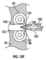
プラグユニットおよびレセプタクルユニットの嵌合解放時にプラグマニホールドおよびレセプタクルマニホールドがプラグ外殻ボアに対して外向きに動く際のアクチュエータロッド128の動作が図13E〜図13Gに示されている。レセプタクルユニットがプラグ外殻ボアから出る際、プラグマニホールドはバネ24の作用の下で外向きに付勢される。アクチュエータロッド126,128は図13Eの矢印により示されるようにレセプタクルマニホールドポート20,22から出始め、プラグマニホールドポート124,125に戻る。図13Gで示される様に、ロッド128がポート122から矢印の方向に動く際、枝部158の端部上のノッチ160のアクチュエータ表面160Bはローリングシールタブ109に接触する。ロッド128はポートから出て、タブ109が図13Fで示されるようにチャンバ140とポート122との間の接続部において前方端部壁149と接触するまで、タブ109を右に押し続ける。これは、タブがさらに動くことを防止する。この動きの間、ローリングシール88は図3における開位置から図2に示す閉位置まで回転して戻される。次に枝部は、突起160がタブ109を越え、図13Gで示されるようにロッド128が完全にポート122から出てプラグマニホールドの位置合わせされたポート125に戻るよう、一緒に押される。シール88を閉止するロッド128の動作と同時に、ロッド126はシール32を同様の様式で閉位置へと回転させる。この時点においてコレットスリーブはレセプタクル外殻を開放しており、プラグマニホールドおよびレセプタクルマニホールドは分離され得る。   The operation of the actuator rod 128 when the plug manifold and the receptacle manifold move outwardly with respect to the plug shell bore when the plug unit and the receptacle unit are fitted and released is shown in FIGS. 13E to 13G. As the receptacle unit exits the plug shell bore, the plug manifold is biased outward under the action of the spring 24. Actuator rods 126 and 128 begin to exit receptacle manifold ports 20 and 22 as shown by the arrows in FIG. 13E and return to plug manifold ports 124 and 125. As shown in FIG. 13G, the actuator surface 160B of the notch 160 on the end of the branch 158 contacts the rolling seal tab 109 as the rod 128 moves from the port 122 in the direction of the arrow. Rod 128 exits the port and continues to push tab 109 to the right until tab 109 contacts front end wall 149 at the connection between chamber 140 and port 122 as shown in FIG. 13F. This prevents the tab from moving further. During this movement, the rolling seal 88 is rotated back from the open position in FIG. 3 to the closed position shown in FIG. The branches are then pushed together so that the protrusion 160 passes over the tab 109 and the rod 128 completely exits the port 122 and returns to the aligned port 125 of the plug manifold as shown in FIG. 13G. Simultaneously with the movement of the rod 128 to close the seal 88, the rod 126 rotates the seal 32 to the closed position in a similar manner. At this point the collet sleeve has opened the receptacle shell and the plug manifold and receptacle manifold can be separated.

先行技術に係るローリングシールコネクタでは、中心アクチュエータロッドが何らかの理由により変形されると、コネクタユニットの嵌合解放時にレセプタクルシールが完全に閉止されないリスクが存在する。レセプタクルユニットにおけるそれぞれのローリングシール88と組み合わせて、図6〜図12Bで図示し上述したようなトーションバネ202などのアクチュエータ支援または付勢装置を使用することは、中心アクチュエータに変形が生じたか否かに関わらず、コネクタの嵌合が解放される度に、シールを閉止することまたは実質的に閉止することを支援する。図13Gで見られるようにポート122から出る前に中心アクチュエータがシールを完全な閉位置に付勢しない場合、アクチュエータロッドが図13Fで示される位置におけるポート122から出始めると速やかにトーションバネ202の付勢作用がシールを閉位置に向かって付勢する。このことは、アクチュエータに損傷が生じた場合に、コネクタにおける冗長性の手段を提供する。   In the rolling seal connector according to the prior art, if the central actuator rod is deformed for some reason, there is a risk that the receptacle seal is not completely closed when the connector unit is released. Using an actuator assisting or biasing device, such as a torsion spring 202 as shown in FIGS. 6-12B and described above, in combination with each rolling seal 88 in the receptacle unit, determines whether the central actuator has been deformed or not. Regardless, it assists in closing or substantially closing the seal each time the connector mating is released. If the central actuator does not urge the seal to the fully closed position before exiting the port 122 as seen in FIG. 13G, the torsion spring 202 will immediately move as the actuator rod begins to exit the port 122 in the position shown in FIG. 13F. The biasing action biases the seal toward the closed position. This provides a means of redundancy in the connector if the actuator is damaged.

一実施形態では、アクスル端部部分およびトーションバネ202を受容するマニホールドボア部分206の直径はおよそ0.25〜0.35インチであった。それぞれのバネ202は、ボア部分直径に等しい最大外径と、0.10〜0.20インチの範囲の内径と、を有した。一実施形態では、それぞれのマニホールドボア部分206の直径は0.29インチであった。それぞれのバネ202の最大外径は0.29インチであった。それぞれのバネ202の最小内径は0.16インチであった。バネ端部が外向きまたは上向きに曲げられてマニホールドブロックにおける受容ボアまたは座部に係合する状態で、バネ高さはおよそ0.15〜0.20インチであり、1つの事例では、0.18インチであった。所望により、より大きいバネおよび増加された付勢力を提供するために、バネの外径および高さは増加されてもよい。一実施形態では、シールアクスルはPEEK(ポリエーテルケトン)または同様の硬質プラスチック材料であった。その一方で、マニホールドブロックはDelrin(登録商標)などのエンジニアリング用熱可塑性材料であった。金属などの他の材料も代替的な実施形態において使用され得る。   In one embodiment, the diameter of the manifold bore portion 206 that receives the axle end portion and the torsion spring 202 was approximately 0.25 to 0.35 inches. Each spring 202 had a maximum outer diameter equal to the bore portion diameter and an inner diameter in the range of 0.10 to 0.20 inches. In one embodiment, the diameter of each manifold bore portion 206 was 0.29 inches. The maximum outer diameter of each spring 202 was 0.29 inches. The minimum inner diameter of each spring 202 was 0.16 inches. With the spring end bent outward or upward to engage the receiving bore or seat in the manifold block, the spring height is approximately 0.15 to 0.20 inches, and in one case, 0. It was 18 inches. If desired, the outer diameter and height of the spring may be increased to provide a larger spring and increased biasing force. In one embodiment, the seal axle was PEEK (polyetherketone) or similar rigid plastic material. On the other hand, the manifold block was an engineering thermoplastic material such as Delrin®. Other materials such as metals may also be used in alternative embodiments.

上記の実施形態においてローリングシールの閉止を支援するために使用されるトーションバネは、製造が比較的容易である。ローリングシールアクスルは、バネが装着され得る拡張された部分を提供するにあたっては、バネ高さに等しい量またはバネ高さよりもわずかに大きい量だけ、一方の端部におけるローリングシールアクスルの長さが大きくなるよう、わずかに変更されるだけでよい。この設計は、ローリングシールアクスルがアクスルを保持する幾何学的形状(例えばボア部分205)との接触を保持することを確保する。右側のシールが図6で見られるように時計方向に回転し左側のバネが反時計回りに回転する状態で、2つのローリングシールが反対方向に回転するため、バネ202は、内側または第1の端部がアクスルシャフトに固定され外側または第2の端部がレセプタクルマニホールドブロックに固定された状態で、同じ方向ではなく替わって反対方向に巻回される(図6参照)。それぞれのシールの内側端部208を受容するための開口部またはボアが左側および右側のシール上で異なって配置されているため、左側および右側のシールのアクスルも同じではない。   The torsion spring used to assist in closing the rolling seal in the above embodiment is relatively easy to manufacture. The rolling seal axle has an increased length where the rolling seal axle at one end is increased by an amount equal to or slightly greater than the spring height in providing an expanded portion on which the spring can be mounted. It only needs to be changed slightly to become. This design ensures that the rolling seal axle maintains contact with the geometry (eg, bore portion 205) that holds the axle. With the right seal rotating clockwise as seen in FIG. 6 and the left spring rotating counterclockwise, the two rolling seals rotate in opposite directions so that the spring 202 is either inward or first With the end fixed to the axle shaft and the outer or second end fixed to the receptacle manifold block, it is wound in the opposite direction instead of the same direction (see FIG. 6). The axles of the left and right seals are not the same because the openings or bores for receiving the inner end 208 of each seal are arranged differently on the left and right seals.

図14〜図25では、閉位置と開位置との間で前後に動くようアクチュエータロッドにより作動されるプラグユニット310およびプラグユニット312内のローリングシールと、少なくともレセプタクルユニット312内のローリングシールを閉止密閉位置に向かって付勢するためのアクチュエータ支援装置と、を有するローリングシールコネクタ380の第2の実施形態が図示されている。この実施形態は、いくつかの側面において以前の実施形態と異なる。第1に、それぞれのアクチュエータ支援装置は、トーションバネよりもむしろ、図20Aおよび図20Bに最もわかりやすく図示されている時計バネ360(すなわち平坦な細片が螺旋形状に巻回されているバネ)である。第2に、レセプタクルユニット内のローリングシールは、閉位置と開位置との間で、以前の実施形態におけるプラグユニット内のローリングシールが回転するように反対方向にではなく、同一方向に回転し、アクチュエータロッドおよびアクチュエータロッドを受容するための通路は、以下でより詳細に説明するように変更される。第3に、アクチュエータ支援装置は、第1の実施形態とは反対側のシールの端部におけるアクスル部分上に装着される。トーションバネまたは時計バネの一方が2つの実施形態のうちのいずれかで使用され得、ローリングシールのいずれかの端部におけるアクスル延長部分上に装着され得ることを理解されたい。   14 to 25, the plug unit 310 and the rolling seal in the plug unit 312 operated by the actuator rod to move back and forth between the closed position and the open position, and at least the rolling seal in the receptacle unit 312 are closed and sealed. A second embodiment of a rolling seal connector 380 is shown having an actuator assist device for biasing toward position. This embodiment differs from previous embodiments in several aspects. First, each actuator support device is not a torsion spring, but a clock spring 360 (ie, a spring in which a flat strip is wound in a spiral shape), which is best illustrated in FIGS. 20A and 20B. It is. Secondly, the rolling seal in the receptacle unit rotates in the same direction between the closed position and the open position, not in the opposite direction so that the rolling seal in the plug unit in the previous embodiment rotates, The actuator rod and the passage for receiving the actuator rod are modified as described in more detail below. Thirdly, the actuator assisting device is mounted on the axle part at the end of the seal opposite to the first embodiment. It should be understood that either a torsion spring or a watch spring can be used in either of the two embodiments and can be mounted on the axle extension at either end of the rolling seal.

この実施形態におけるコネクタは、12芯コネクタであり、光ファイバを接続するための光コネクタである。以前の実施形態におけるように、図14〜図25のコネクタは、電気接続のみの用途として、または電気接続および光ファイバ接続の両方の用途として、変更され得る。加えて、コネクタは代替的に用途に応じて、より多数の接続、またはより少数の接続を行うよう、設計され得ることも理解されるであろう。コネクタは、水中での用途で使用されることが特に意図されたものではあるが、水中または深海のみではなく、あらゆる過酷な環境における接続のために使用され得る。これらの差異とは別に、コネクタ380は図1〜図13のコネクタと同様であり、したがってコネクタの同様のパーツ(接点および圧力補償接点チャンバなど)は詳細には説明または図示されない。   The connector in this embodiment is a 12-core connector, which is an optical connector for connecting an optical fiber. As in previous embodiments, the connectors of FIGS. 14-25 can be modified for electrical connection only applications or for both electrical and fiber optic connection applications. In addition, it will be appreciated that the connector may alternatively be designed to make more or fewer connections depending on the application. The connectors are specifically intended for use in underwater applications, but can be used for connections in any harsh environment, not just underwater or deep water. Apart from these differences, connector 380 is similar to the connector of FIGS. 1-13, and therefore similar parts of the connector (such as contacts and pressure compensating contact chambers) are not described or illustrated in detail.

この実施形態におけるコネクタは、コネクタユニットを水中で着脱するときにROV操作アームによる係合のためのレセプタクルユニット312の外側コネクタハウジング390上のフライングリードハンドル用のROV(遠隔操作車両)接続構造316とともに示される一方で、プラグユニットは隔壁などに接続するための環状接続フランジ(図示せず)を有する。係る装置は当該技術分野において周知であり、したがって詳細には説明されない。   The connector in this embodiment, together with the ROV (remote control vehicle) connection structure 316 for the flying lead handle on the outer connector housing 390 of the receptacle unit 312 for engagement by the ROV operation arm when the connector unit is attached and detached underwater. While shown, the plug unit has an annular connection flange (not shown) for connection to a bulkhead or the like. Such devices are well known in the art and are therefore not described in detail.

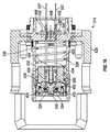
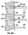
プラグユニットおよびレセプタクルユニットの他の詳細は、変更されたローリングシールの動作を説明する際の簡素化のために、図14〜図18では省略され、省略された詳細は先に説明した第1の実施形態と同様であるか、または同等である。図14および図15に示すようにレセプタクルユニット312は、外側コネクタハウジング390内に固定された剛性の外側殻体315を有する。レセプタクル外殻315は、終端または後端部壁317と、前方端部から内向きに突出する円筒形ボア321と、を有する。剛性物質製のレセプタクルマニホールドブロックまたは前方端部部分314は、好適な保持ネジ(図示せず)を介して外殻315内のアクスルマウント319に固定され、それによりブロック314の後端部と端部壁317と間のチャンバに内袋の外側の部分が残されることとなる。係る内袋の外側の部分はユニットの外部とベントポート(図示せず)を介して連通する。一連の貫通ボアまたは通路370がマニホールドブロック314を通って延び、ブロック314の前方端部におけるスロット状の開口部323を有する1対の部分円筒形座部または凹陥部321において終端する。ローリングシール装置318が座部321のうちのそれぞれの座部において回転可能に装着され、それにより図14および図15に示す閉位置においてボア370の開放された前方端部がシールされる。上述のように、貫通ボアの個数は想定される接続の個数に対応し、この場合においては、6つの平行ボアがマニホールドのそれぞれの半体に提供される。それらのうちの1つずつが図15で見られる。以下でより詳細に説明されるように、ボアは、ユニット312の開放された嵌合された状態ではローリングシール318における対応するボアと位置合わせされる。位置合わせされた貫通ボア372が後端部壁317に提供され、図15に示すように、電気および光用の管状ハウジング375がボア372を通って位置合わせされたボア370へと突出する。   Other details of the plug unit and receptacle unit are omitted in FIGS. 14-18 for the sake of simplicity in describing the operation of the modified rolling seal, and details omitted are the first described above. It is similar to or equivalent to the embodiment. As shown in FIGS. 14 and 15, the receptacle unit 312 has a rigid outer shell 315 fixed in the outer connector housing 390. The receptacle shell 315 has a terminal or rear end wall 317 and a cylindrical bore 321 that protrudes inwardly from the front end. A rigid manifold receptacle manifold block or front end portion 314 is secured to an axle mount 319 in the outer shell 315 via a suitable retaining screw (not shown), thereby allowing the rear and end portions of the block 314 to end. The outer portion of the inner bag is left in the chamber between the walls 317. The outer portion of the inner bag communicates with the outside of the unit via a vent port (not shown). A series of through bores or passages 370 extend through the manifold block 314 and terminate in a pair of partial cylindrical seats or recesses 321 having a slot-like opening 323 at the forward end of the block 314. A rolling seal device 318 is rotatably mounted at each of the seats 321 so that the open front end of the bore 370 is sealed in the closed position shown in FIGS. As mentioned above, the number of through bores corresponds to the number of connections envisaged, in which case six parallel bores are provided in each half of the manifold. One of them can be seen in FIG. As described in more detail below, the bores are aligned with corresponding bores in the rolling seal 318 when the unit 312 is in the open and mated state. An aligned through bore 372 is provided in the rear end wall 317, and an electrical and optical tubular housing 375 projects through the bore 372 into the aligned bore 370, as shown in FIG.

光ファイバ325は管状ハウジング375のボアを通り、アライメントフェルール381へと終端する。アライメントフェルール381はそれぞれの管状ハウジング375の端部における座部に固定される。光ファイバをアライメントフェルールに接続することは標準的なエポキシ研磨技術を使用して行われる。以前の実施形態のシールと同様の好適なシール(図示せず)が、端部壁をシールするためにそれぞれのハウジング375と、後方端部壁ボア372と、の間に、およびそれぞれのハウジング375と、マニホールドブロック314を通るボア370と、の間に、提供される。   The optical fiber 325 passes through the bore of the tubular housing 375 and terminates in the alignment ferrule 381. The alignment ferrule 381 is fixed to a seat at the end of each tubular housing 375. Connecting the optical fiber to the alignment ferrule is done using standard epoxy polishing techniques. A suitable seal (not shown) similar to the seal of the previous embodiment is between each housing 375 and the rear end wall bore 372 to seal the end walls and each housing 375. And a bore 370 through the manifold block 314.

バッキングプレート283が装着ネジ284を介して後端部壁およびハウジング375の上方で固定され、この組み立てによりレセプタクルユニットの終端端部において不浸透性の高圧バリアが形成される。ゴム製応力軽減部材またはブーツ289が、バッキングプレート283の外側の電気および光リード線の突出部分端部の上方でシールされる。   A backing plate 283 is secured over the rear end wall and housing 375 via mounting screws 284, and this assembly forms an impermeable high pressure barrier at the terminal end of the receptacle unit. A rubber stress relief member or boot 289 is sealed above the protruding portion ends of the electrical and optical leads outside the backing plate 283.

マニホールドブロック314は中心の内部チャンバ392を有する。柔軟な補償器シール394がチャンバ392の後端部壁を横切って配置され、好適な締結具(図示せず)を介してブロック314の内側端部を横切って固定されているバッキングプレート395を用いて固定される。シール394は管状ハウジング375のうちのそれぞれのハウジングの周りにおけるモリソンシールとして作用する。柔軟な内袋397がシール394からチャンバ392へと突出し、第1の実施形態に関連して上記で説明したのと同様の様式で外部環境と連通する。内袋397の外側のチャンバ392の部分は誘電性の光学的に透明な流体で充填されている接点チャンバを形成する。   Manifold block 314 has a central interior chamber 392. Using a backing plate 395 in which a flexible compensator seal 394 is positioned across the rear end wall of the chamber 392 and secured across the inner end of the block 314 via suitable fasteners (not shown). Fixed. Seals 394 act as Morrison seals around each of the tubular housings 375. A flexible inner bag 397 projects from the seal 394 into the chamber 392 and communicates with the external environment in a manner similar to that described above in connection with the first embodiment. The portion of the chamber 392 outside the inner bag 397 forms a contact chamber filled with a dielectric optically clear fluid.

図20A〜図22Bに最もわかりやすく図示されているように、レセプタクルマニホールドブロック314は拡大された前端部分400を有する略円筒形の形状である。前端部分400は、外側端部表面404から内向きに延びる切り抜き部分402(図20A参照)を有する。以前の実施形態におけるように切り抜き部分402は、それぞれのローリングシール318を受容する部分円筒形座部321のうちのそれぞれの座部の第1端部を横切って延びる端部表面405を有し、合致する弓形状ブロック部分319は切り抜き部分402に係合する。4つの長方形または正方形のアクチュエータ受容ボアまたは通路は、図14、図20A、図20B、および図21に最もわかりやすく図示されているように、ローリングシール318の第1端部の近位においてブロック部分319と、マニホールドブロック314の合致する受容部分407と、を通って直線状に延びる。図16〜図19および図24A〜図24Dに関連して以下でより詳細に説明するように、2つのボア320はレセプタクルローリングシール318を作動させるためのアクチュエータロッドを受容するよう設計され、他方の2つのボア322はプラグローリングシールを作動させるアクチュエータロッドを受容するよう設計されている。ボア320,322は、嵌合の際にボアに延びるアクチュエータロッドの断面寸法よりもわずかに大きい長方形または正方形の断面を有する。   As best shown in FIGS. 20A-22B, the receptacle manifold block 314 has a generally cylindrical shape with an enlarged front end portion 400. The front end portion 400 has a cutout portion 402 (see FIG. 20A) that extends inwardly from the outer end surface 404. As in previous embodiments, the cutout portion 402 has an end surface 405 that extends across the first end of each of the partial cylindrical seats 321 that receive the respective rolling seal 318, and The matching arcuate block portion 319 engages the cutout portion 402. Four rectangular or square actuator receiving bores or passages are provided in the block portion proximal to the first end of the rolling seal 318, as best seen in FIGS. 14, 20A, 20B, and 21. It extends linearly through 319 and the mating receiving portion 407 of the manifold block 314. As described in more detail below in connection with FIGS. 16-19 and 24A-24D, the two bores 320 are designed to receive an actuator rod for actuating the receptacle rolling seal 318, while the other The two bores 322 are designed to receive actuator rods that actuate the plug rolling seal. The bores 320, 322 have a rectangular or square cross section that is slightly larger than the cross sectional dimension of the actuator rod that extends into the bore when mated.

プラグユニット310は図16〜図19で図示され、外側コネクタハウジングまたは本体420を有する。シールされた後端部壁344と開放された前方端部424とを有する円筒形外殻332は、ボルトまたは締結具421を介して外側本体420の後端部に固定される。剛性物質製のプラグ接点マニホールドまたは前端部分330が、プラグチャンバ435において摺動可能に装着され、図17および図18に示す前方位置へと付勢バネ338により付勢されている。   The plug unit 310 is illustrated in FIGS. 16-19 and has an outer connector housing or body 420. A cylindrical outer shell 332 having a sealed rear end wall 344 and an open front end 424 is secured to the rear end of the outer body 420 via bolts or fasteners 421. A plug contact manifold or front end portion 330 made of rigid material is slidably mounted in the plug chamber 435 and is biased by a biasing spring 338 to the forward position shown in FIGS.

プラグマニホールドは、圧力補償された内部チャンバ428と、チャンバ428からマニホールドの前方端部に延びる一連の平行な貫通ボア426と、を有する。これらの貫通ボア426のうち2つの貫通ボアが図18に図示されている。想定される接続の個数に依存してより少数またはより多数の接続が形成され得るが、ボアの個数は想定される接続(この場合では12個)の個数に依存する。これらのボアのうち6つのボアがマニホールドブロック330の一方の半体に配置され、残りの6つのボアはマニホールドブロックの他方の半体に配置されている。これらのボアは、マニホールドの正面に配置された1対の平行な部分円筒形凹陥部またはローリングシール座部430において終端する(図16および図18参照)。なおここでは、6つのボアが一方の凹陥部において終端し、残りの6つのボアが他方の凹陥部において終端している。1対のローリングシール334がそれぞれの凹陥部430において回転可能に装着されている。ボア426の端部は図16ではローリングシール334により隠されているが、これらの端部が、左側の凹陥部の近位にある番号1〜番号6と、右側の凹陥部の近位にある番号7〜番号12と、略位置合わせされていることが理解されるであろう。   The plug manifold has a pressure compensated internal chamber 428 and a series of parallel through bores 426 extending from the chamber 428 to the forward end of the manifold. Of these through bores 426, two through bores are illustrated in FIG. Depending on the number of connections envisaged, fewer or more connections can be made, but the number of bores depends on the number of connections envisioned (in this case 12). Of these bores, six bores are arranged in one half of the manifold block 330 and the remaining six bores are arranged in the other half of the manifold block. These bores terminate in a pair of parallel partial cylindrical recesses or rolling seal seats 430 located in front of the manifold (see FIGS. 16 and 18). Here, six bores terminate in one recess and the remaining six bores terminate in the other recess. A pair of rolling seals 334 are rotatably mounted at each recess 430. The ends of the bore 426 are hidden in FIG. 16 by the rolling seal 334, but these ends are proximal to the left recess and numbers 1 through 6 and the right recess. It will be understood that it is generally aligned with numbers 7-12.

外殻端部壁344における一連の貫通ボア432のそれぞれは、マニホールド貫通ボア430のうちのそれぞれの貫通ボアと位置合わせされている。接点チャンバを画成する一連の光ファイバハウジング434は、それぞれの位置合わせされたボア432と、プラグ外殻332内のチャンバ435と、を通って、マニホールドブロック330へと突出する。光ファイバ337は光ファイバハウジング434のボアを貫通し、それぞれの管状ハウジング434の端部における座部に固定されているアライメントフェルールへと終端する。以前の実施形態におけるように、ハウジング434のうちのそれぞれのハウジングはOリングシールを介して端部壁344におけるそれぞれのボア432にシールされる。バッキングプレート436が装着ネジ448を介して後端部壁およびハウジング434の上方で固定され、この組み立てによりプラグユニットの終端端部において不浸透性の高圧バリアが形成される。ゴム製応力軽減部材またはブーツ449が、それぞれのハウジング434の突出端部と、プレート436の外側上の光リード線と、の上方で固定される。   Each of the series of through bores 432 in the outer shell end wall 344 is aligned with a respective through bore in the manifold through bore 430. A series of fiber optic housings 434 that define a contact chamber project through the respective aligned bore 432 and chamber 435 in the plug shell 332 into the manifold block 330. The optical fiber 337 passes through the bore of the optical fiber housing 434 and terminates in an alignment ferrule that is secured to a seat at the end of each tubular housing 434. As in previous embodiments, each of the housings 434 is sealed to a respective bore 432 in the end wall 344 via an O-ring seal. A backing plate 436 is secured over the rear end wall and housing 434 via mounting screws 448, and this assembly forms an impermeable high pressure barrier at the terminal end of the plug unit. A rubber stress relief member or boot 449 is secured above the protruding end of each housing 434 and the optical leads on the outside of the plate 436.

誘電性流体が、ボア426のうちのそれぞれのボアの前方端部を充填する。チャンバ428内の部材450は、適宜内向きまたは外向きに曲がることにより、チャンバ428の内部の流体と外部の流体との間で圧力補償を提供する柔軟な蛇腹またはダイヤフラムである。   A dielectric fluid fills the forward end of each of the bores 426. The member 450 in the chamber 428 is a flexible bellows or diaphragm that provides pressure compensation between the fluid inside and outside the chamber 428 by bending inward or outward as appropriate.

図17に最もわかりやすく図示されているように、2対のアクチュエータロッド346および358は前方に向かってチャンバ435を通り、それぞれ、プラグマニホールドブロック330内の、位置合わせされた対をなすポートまたは通路340,342に延びる。通路340,342はマニホールドブロック330を通って延び、マニホールドブロックの外側表面335において開いている。図19に示すように、アクチュエータロッドの対が交互配置された状態で、換言すると、アクチュエータロッド36およびアクチュエータロッド348がプラグユニットチャンバを横切る方向において交互に配列されている状態で、アクチュエータロッドは直線状に配列され、アクチュエータマウント422から前方に向かって延びる。これらの通路はアクチュエータロッド346,348に対して合致する長方形または正方形の断面であり、アクチュエータロッドがこれらの通路を通ること、およびこれらの通路から出ることを可能にするために、これらのアクチュエータロッドよりもわずかに大きい寸法である。図16〜図18の嵌合が解放された状態では、アクチュエータロッドはマニホールドブロック330の前端部表面335から突き出た前方端部を有し得る。嵌合されている間、ポート340はレセプタクルマニホールドブロック314内の対応するアクチュエータ受容ポート320と位置合わせされる一方で、ポート342の対はレセプタクルマニホールドブロック内の対応するポート322と位置合わせされる。   As best seen in FIG. 17, two pairs of actuator rods 346 and 358 pass forward through chamber 435 and each form a pair of aligned ports or passages in plug manifold block 330. 340, 342. The passages 340, 342 extend through the manifold block 330 and open at the outer surface 335 of the manifold block. As shown in FIG. 19, in a state where pairs of actuator rods are arranged alternately, in other words, in a state where the actuator rods 36 and the actuator rods 348 are alternately arranged in the direction across the plug unit chamber, And extends forward from the actuator mount 422. These passages have a rectangular or square cross section that conforms to the actuator rods 346, 348, and these actuator rods are used to allow the actuator rods to pass through and out of these passages. The dimensions are slightly larger than. In the released state of FIGS. 16-18, the actuator rod may have a forward end protruding from the front end surface 335 of the manifold block 330. While mated, the port 340 is aligned with the corresponding actuator receiving port 320 in the receptacle manifold block 314 while the pair of ports 342 are aligned with the corresponding port 322 in the receptacle manifold block.

レセプタクルユニットのローリングシール318は第1の実施形態のローリングシール88といくつかの点で同様であり、これらのシールのように、それぞれのレセプタクルローリングシールは剛性コア366を備え、剛性コア366上には弾性状ローラまたはスリーブ368が成型されるかまたは別様に固定される。このコアは金属製または硬質プラスチック製であり、コア366の反対端部から突出する一体的な小径アクスル端部またはアクスル部分367および370を有する(図22Aおよび図22B参照)。一方のアクスル部分367は反対側のアクスル部分よりも短く、それぞれのローリングシール座部321の第2端部の近位にある合致する座部またはボア371に回転可能に係合する。   The receptacle unit rolling seal 318 is similar in some respects to the rolling seal 88 of the first embodiment, and like these seals, each receptacle rolling seal includes a rigid core 366 on the rigid core 366. The elastic roller or sleeve 368 is molded or otherwise fixed. The core is made of metal or hard plastic and has an integral small diameter axle end or axle portion 367 and 370 protruding from the opposite end of the core 366 (see FIGS. 22A and 22B). One axle portion 367 is shorter than the opposite axle portion and rotatably engages a matching seat or bore 371 proximal to the second end of each rolling seal seat 321.

レセプタクルマニホールドの本体内のより大きい直径のアクスル部分329はコア366の反対端部から延び、図20Aおよび図20Bで見られるように、切り取り端部表面405から突出する。径方向タブまたは歯状物328は図20A、図20B、図22A、および図22Bで見られるようにアクスル部分329からそれぞれのアクチュエータボア320へと突出する。直径がより小さい端部部分370はアクスル部分329から突出する。シールコア366およびそれを包囲するスリーブは、ローリングシールを横断的に通過する貫通孔365を有する。アクチュエータ支援装置または時計バネ360は図20A、図20B、図22A、および図22Bに最もわかりやすく図示されているように小径突起アクスルまたは端部部分370上に装着される。この構成は、以前の実施形態(アクチュエータ支援装置が、アクチュエータ係合タブとは反対側のローリングシールアクスルの端部上に装着されていた)とは異なる。   A larger diameter axle portion 329 within the body of the receptacle manifold extends from the opposite end of the core 366 and protrudes from the cut end surface 405 as seen in FIGS. 20A and 20B. A radial tab or tooth 328 protrudes from the axle portion 329 into the respective actuator bore 320 as seen in FIGS. 20A, 20B, 22A, and 22B. A smaller diameter end portion 370 protrudes from the axle portion 329. The seal core 366 and the sleeve surrounding it have a through hole 365 that passes transversely through the rolling seal. Actuator assist device or watch spring 360 is mounted on small diameter axle or end portion 370 as best shown in FIGS. 20A, 20B, 22A, and 22B. This configuration is different from the previous embodiment (the actuator support device was mounted on the end of the rolling seal axle opposite the actuator engagement tab).

この実施形態では、アクチュエータ支援装置は時計バネ360を備えるが、他の実施形態では他種類のバネまたは他の付勢装置が使用されてもよい。時計シール360が装着されているシール318の拡張されたアクスル端部部分329を除き、プラグローリングシール334はレセプタクルシールと同等である。この実施形態におけるプラグユニットではアクチュエータ支援装置が提供されていないため、アクスル端部部分329はプラグローリングシール上に存在しない。レセプタクルローリングシールの場合におけるように、プラグローリングシールの拡大された端部部分は突起するアクチュエータタブ350を有する。アクチュエータタブ350は、嵌合が、および嵌合の解放が、行われるときにアクチュエータロッド348により係合されるために、通路342に延びる。代替的な実施形態において必要であるならば、プラグシール334は、アクチュエータ付勢装置の装着がプラグシールのアクスルまたはシャフト上で、ならびに、レセプタクルシールのアクスルまたはシャフト上で、可能となるよう変更されてもよい。   In this embodiment, the actuator support device comprises a watch spring 360, although other types of springs or other biasing devices may be used in other embodiments. With the exception of the expanded axle end portion 329 of the seal 318 to which the watch seal 360 is attached, the plug rolling seal 334 is equivalent to a receptacle seal. Because the actuator unit is not provided in the plug unit in this embodiment, the axle end portion 329 is not present on the plug rolling seal. As in the case of a receptacle rolling seal, the enlarged end portion of the plug rolling seal has a protruding actuator tab 350. The actuator tab 350 extends into the passage 342 for engagement and release of the engagement by the actuator rod 348 as it occurs. If required in alternative embodiments, the plug seal 334 may be modified to allow attachment of the actuator biasing device on the plug seal axle or shaft as well as on the receptacle seal axle or shaft. May be.

レセプタクルローリングシール318のうちのそれぞれのローリングシールの本体は、レセプタクルマニホールドブロック314の正面404へと開かれている、合致する座部321に回転可能に係合される一方で、本体の反対端部におけるアクスル端部部分は、それぞれの凹陥部または座部321の反対端部におけるレセプタクルマニホールドの対応するカウンタボアに回転可能に装着される。   The body of each of the rolling rolling seals 318 is rotatably engaged with a mating seat 321 that is open to the front 404 of the receptacle manifold block 314 while the opposite end of the body. Axle end portions are rotatably mounted in corresponding recesses in the receptacle manifold at the opposite end of each recess or seat 321.

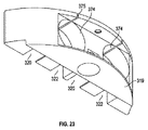
渦巻きおよび螺旋状に巻回されたトーションバネとは異なり、時計バネ360は、図20Aおよび図20Bに示すように、反対の内側および外側の端部部分351および362が互いに対して軸方向にずれることがないよう、金属製または他の材料製の細片をゼンマイ状に巻回することにより形成される。この構成は、以前の、渦巻き状に巻回されたバネよりも大きい直径のエンベロープまたは装着ボアを必要とするが、軸方向長さはより短くなる。以前の実施形態(アクチュエータ支援バネが、アクチュエータタブとは反対側にあるアクスルの端部上の主要マニホールドブロックに装着されている)とは異なり、この実施形態における時計バネ360は、図22A〜図23に最もわかりやすく図示されているように、アクチュエータロッド受容通路およびアクチュエータタブ328を担持する拡大されたアクスル部分329も備える、より小さい弓形状ブロックパーツ319におけるカウンタボア374に装着される。それぞれのバネの内側端部部分361はそれぞれのアクスル端部部分370においてその目的のために提供された径方向スロットに装着される一方で(図20Aおよび図20B参照)、バネ360の外側端部部分362は、図23で見られるようにカウンタボア374と連通するマニホールドブロックパーツ319の内側端部壁におけるそれぞれのスロットまたはバネ座部375に延びる。カウンタボア374の露出された外側端部は、ブロック部分319がシールアクスルの露出された端部およびバネの上方で凹み402に装着された後に、好適に蓋で覆われシールされ得る。   Unlike the spiral and helically wound torsion springs, the watch spring 360 is configured such that the opposite inner and outer end portions 351 and 362 are axially offset relative to each other, as shown in FIGS. 20A and 20B. In order to prevent this, it is formed by winding a strip made of metal or other material into a spring shape. This configuration requires a larger diameter envelope or mounting bore than the previous spirally wound spring, but with a shorter axial length. Unlike previous embodiments (actuator assisted springs are mounted on the main manifold block on the end of the axle opposite the actuator tab), the watch spring 360 in this embodiment is shown in FIGS. 23 is mounted on a counterbore 374 in a smaller arcuate block part 319 that also includes an enlarged axle portion 329 that carries an actuator rod receiving passage and an actuator tab 328. The inner end portion 361 of each spring is mounted in a radial slot provided for that purpose at each axle end portion 370 (see FIGS. 20A and 20B), while the outer end portion of the spring 360. Portions 362 extend into respective slots or spring seats 375 in the inner end wall of manifold block part 319 that communicate with counterbore 374 as seen in FIG. The exposed outer end of the counterbore 374 can be suitably covered and sealed after the block portion 319 is mounted in the recess 402 above the exposed end of the seal axle and the spring.

図20A、図21、および図22Aでは、閉止密閉位置にあるローリングシール318が図示されている。これらの図面で見られるように、この位置では、(図6および図13Aで示されているように、アクチュエータタブ109が同一の中心アクチュエータボアに向かって内向きに反対方向に向けられている、以前の実施形態とは異なり)両方のアクチュエータタブ328はレセプタクルマニホールドブロックの前方に向けられ、別個のアクチュエータロッド受容通路320へと同一方向に対向している。同様に、プラグローリングシール334のアクチュエータタブ350も、図17のシールされた位置においてプラグマニホールドブロックの後方に向けられ、以前の実施形態におけるように反対方向に向けられるよりもむしろ、別個のアクチュエータ通路342へと同一の方向に対向している。   20A, 21 and 22A, the rolling seal 318 is shown in a closed and sealed position. As can be seen in these drawings, in this position (as shown in FIGS. 6 and 13A, the actuator tab 109 is oriented inwardly in the opposite direction toward the same central actuator bore, Both actuator tabs 328 are directed forward of the receptacle manifold block (unlike previous embodiments) and face the same direction to a separate actuator rod receiving passage 320. Similarly, the actuator tab 350 of the plug rolling seal 334 is also directed to the rear of the plug manifold block in the sealed position of FIG. 17 and is a separate actuator passage rather than in the opposite direction as in the previous embodiment. 342 in the same direction.

閉止密閉位置では、時計バネ360の端部は、バネが弛緩した状態または負荷以前の状態となるよう、配置され得る。図20Aで見られるように、この位置では、バネ端部部分361は外側バネ端部部分362に対して90度の角度に向けられている。図20Bでは、開位置へと回転されたローリングシール318が図示されている。内側端部部分361は、シールアクスル370がバネの外側端部に対して90度の角度となるよう、図20Aの閉位置から図20Bの開位置に回転されている。これにより、バネが変形されてバネに負荷が与えられるよう、バネにおいて追加的な半回転が生じることとなる。図20Bにおける負荷が与えられたバネ360は、閉止状態へと戻るよう、ローリングシールを付勢する。この実施形態では、シール318は同一方向に回転し、両方のバネが開位置において正確に同一の方向に向けられている。このように、バネ360が装着されているアクスル端部部分370と同様に、これらのバネ360も同等である。したがってこの実施形態では、異なる左用および右用のバネが要求されず、また2つのシールに対して異なる左用および右用のアクスル端部部分も要求されず、それにより製造および組み立てが簡素化されることとなる。   In the closed and sealed position, the end of the watch spring 360 may be positioned so that the spring is in a relaxed state or a pre-load state. As seen in FIG. 20A, in this position, the spring end portion 361 is oriented at an angle of 90 degrees with respect to the outer spring end portion 362. In FIG. 20B, the rolling seal 318 is shown rotated to the open position. The inner end portion 361 has been rotated from the closed position of FIG. 20A to the open position of FIG. 20B so that the seal axle 370 is at an angle of 90 degrees with respect to the outer end of the spring. This causes an additional half turn in the spring so that the spring is deformed and loaded. The loaded spring 360 in FIG. 20B urges the rolling seal to return to the closed state. In this embodiment, the seal 318 rotates in the same direction and both springs are oriented in exactly the same direction in the open position. Thus, similar to the axle end portion 370 to which the spring 360 is mounted, these springs 360 are equivalent. Thus, in this embodiment, different left and right springs are not required, and different left and right axle end portions are not required for the two seals, thereby simplifying manufacturing and assembly. It will be.

それぞれレセプタクルローリングシールおよびプラグローリングシールを動作させるアクチュエータロッド346,348は、以前の実施形態のアクチュエータロッド、および上記で参照した米国特許第6,017,227号の先行技術のローリングシールコネクタのアクチュエータロッドとは異なる。特に、以前の実施形態における反対方向に回転する両方のレセプタクルローリングシールを動作させた以前の中心アクチュエータロッドが、両方のローリングシール318を同一方向に回転させる2つの別個のアクチュエータロッド346により置き換えられている。これにより、アクチュエータロッドが変形するリスクが低減される。加えてプラグシールアクチュエータロッド348は、両方のシールを同一方向(レセプタクルシールの回転方向とは逆の方向)に回転させるよう変更され、図17で見られ得るアクチュエータ構造または作動ノッチ440を有する。この作動ノッチ440のそれぞれは、上記で参照した先行技術である米国特許第6,017,227号に記載されているように反対方向に対向するよりもむしろ、同一方向(ロッド346とは反対方向)に対向する。このことによってもまた、製造および組み立てが以前のローリングシールコネクタにおけるよりも簡素化される。   Actuator rods 346, 348 for operating the receptacle rolling seal and the plug rolling seal, respectively, are the actuator rods of the previous embodiment and the actuator rods of the prior art rolling seal connector of US Pat. No. 6,017,227 referenced above. Is different. In particular, the previous central actuator rod that operated both receptacle rolling seals rotating in opposite directions in the previous embodiment has been replaced by two separate actuator rods 346 that rotate both rolling seals 318 in the same direction. Yes. Thereby, the risk that the actuator rod is deformed is reduced. In addition, the plug seal actuator rod 348 is modified to rotate both seals in the same direction (opposite to the direction of rotation of the receptacle seal) and has an actuator structure or actuation notch 440 that can be seen in FIG. Each of these actuating notches 440 is in the same direction (opposite to rod 346) rather than oppositely facing as described in the above referenced prior art US Pat. No. 6,017,227. ). This also simplifies manufacturing and assembly than in previous rolling seal connectors.

図22Aおよび図22Bに示すように、それぞれのアクチュエータポート320はそれぞれのアクスル部分329の(図面において向かって)左側に配置される一方で、アクチュエータポート322はアクスル部分329の反対側または右側に配置される。なおアクチュエータポートの全部がマニホールドブロックの一方の半体において直線状に配列される。同じく交替的なアクチュエータポート構成がプラグマニホールドブロックにも提供される。このこともまた構築を簡素化する。   As shown in FIGS. 22A and 22B, each actuator port 320 is located on the left side (as viewed in the drawing) of each axle portion 329, while actuator port 322 is located on the opposite or right side of axle portion 329. Is done. Note that all of the actuator ports are linearly arranged in one half of the manifold block. An alternate actuator port configuration is also provided for the plug manifold block. This also simplifies construction.

プラグユニットおよびレセプタクルユニットが、図14〜図18、図20A、図21、および図22Aの嵌合が解放された位置と、図20B、図22B、および図25の嵌合された位置との間で動かされるとき、ならびに嵌合された位置から嵌合が解放された位置に戻されるとき、のローリングシールの動作について以下でより詳細に説明する。   The plug unit and the receptacle unit are located between the positions where the mating in FIGS. The operation of the rolling seal when it is moved in, as well as when it is returned from the fitted position to the released position will be described in more detail below.

図17および図18に示すようにプラグユニット内のローリングシールが閉位置にあるとき、アクチュエータロッド348のうちのそれぞれのアクチュエータロッドは、それぞれの通路340の端部において、プラグマニホールドブロック330の前方端部と同一平面状となるかまたは実質的に同一平面状となる端部表面を有する一方で、アクチュエータロッド346の前方端部は図17で見られるように突き出ている。それぞれのアセンブリにおける2つのローリングシール318を開放するためのアクチュエータロッド346の動作が図24Aおよび図24Bに図示されている。   When the rolling seal in the plug unit is in the closed position, as shown in FIGS. While having an end surface that is coplanar or substantially coplanar with the portion, the forward end of the actuator rod 346 protrudes as seen in FIG. The operation of the actuator rod 346 to open the two rolling seals 318 in each assembly is illustrated in FIGS. 24A and 24B.

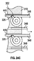
プラグユニットおよびレセプタクルユニットを接続する前、ローリングシール318,334のうちのそれぞれのローリングシールは図14〜図18の閉止密閉位置にある。それぞれのローリングシールは、以前の実施形態におけるように、および図24Aでレセプタクルユニットに対して図示されるように、プラグマニホールドおよびレセプタクルマニホールドの端部表面におけるそれぞれの座部から部分的に外向きに突出する。アクチュエータの動作の図示を明瞭化するために、プラグユニットは図24A〜図24Dでは省略されている。これら2つのユニットが適切な相対的方向で近づけられるにつれて、レセプタクルアクチュエータロッド346を担持する通路340は、レセプタクルマニホールドブロックの前方表面における対応する通路320と位置合わせされる一方で、プラグアクチュエータロッド348を担持する通路342はレセプタクルマニホールドブロックにおける対応する通路322と位置合わせされる。   Prior to connecting the plug unit and the receptacle unit, each of the rolling seals 318, 334 is in the closed sealed position of FIGS. Each rolling seal is partially outward from the respective seat at the end surface of the plug manifold and receptacle manifold, as in the previous embodiment and as illustrated for the receptacle unit in FIG. 24A. Protruding. In order to clarify the operation of the actuator, the plug unit is omitted in FIGS. 24A to 24D. As these two units are brought together in the appropriate relative orientation, the passage 340 carrying the receptacle actuator rod 346 is aligned with the corresponding passage 320 in the front surface of the receptacle manifold block while the plug actuator rod 348 is The carrying passages 342 are aligned with corresponding passages 322 in the receptacle manifold block.

図24Aでは、2つのユニットが最初に対面して係合するよう近づけられる直前における、レセプタクルマニホールドの端部表面に対するロッド346の位置が図示される。これらのコネクタユニットは嵌合動作の第1段階において一緒に押し付けられ、その段階ではプラグローリングシール318およびレセプタクルローリングシール334の突出する部分が平坦化され、これらのローリングシールの対向する表面間から水が効果的に除去され、プラグのローリングシールの表面がレセプタクルのローリングシールの表面に対してシールされる。コネクタユニットがさらに一緒に押圧されると、プラグマニホールド330が内向きに付勢されるにつれてプラグユニットのバネ338が圧縮し始める。同時にロッド346,348は外向きに、または通路340,342の開放端部を通ってさらに外向きに、突き出し始め、レセプタクルマニホールドの位置合わせされた通路320,332へと進入する。このようにレセプタクルがプラグユニット外殻へと動き続けるにつれて、レセプタクルマニホールドブロックは、図24Bに示すように、ロッド346,348により突き刺される。     In FIG. 24A, the position of the rod 346 relative to the end surface of the receptacle manifold is shown just prior to the two units being brought closer to first face-to-face engagement. These connector units are pressed together in the first stage of the mating operation, in which the protruding portions of the plug rolling seal 318 and the receptacle rolling seal 334 are flattened and water is introduced between the opposing surfaces of these rolling seals. Is effectively removed and the surface of the plug rolling seal is sealed against the surface of the receptacle rolling seal. As the connector unit is further pressed together, the plug unit spring 338 begins to compress as the plug manifold 330 is biased inward. At the same time, the rods 346, 348 begin to protrude outward or further outward through the open ends of the passages 340, 342 and enter the aligned passages 320, 332 of the receptacle manifold. As the receptacle continues to move to the plug unit shell in this manner, the receptacle manifold block is pierced by rods 346 and 348 as shown in FIG. 24B.

ロッド346が通路320に進入するにつれて、アクチュエータ構造またはノッチ352は、図24Aに示すように通路320へと部分的に突出する、それぞれのローリングシールタブまたは歯状物328に接触する。ロッド346が矢印の方向で内向きに進入を続けるにつれて、アクチュエータの一方の端部またはノッチ352がタブ328に係合し、それにより2つのローリングシールは、それぞれの長手方向軸を中心にして同一方向(図24Aおよび図24Bで見られるように反時計回り)に、最終的な、図24Bの後ろ向きの方向へと回転する。同時に、プラグアクチュエータロッド348がさらにプラグマニホールドブロック330を通ってレセプタクルマニホールドブロック314内の位置合わせされたボア322へと動くにつれて、それぞれのノッチまたはアクチュエータ部分440(図17)の一方の端部は、プラグユニットにおけるローリングシール334上のそれぞれのタブ350に係合し、それにより、図17の後方に傾斜した位置と、図25で見られるプラグマニホールドブロックの前方端部表面に向かって延びる前方に傾斜した位置との間で、これらのシールを同一方向に、しかもシール318の回転方向とは反対方向(すなわち図25で見ると時計方向)に、回転させる。これは、同時にプラグローリングシールおよびレセプタクルローリングシールの両方を、閉止されたシール状態から開放状態へと移動させる。なおここでは、これらシールを通る通路は、第1の実施形態(図3参照)に関連して上述したのと同じように、プラグユニット内の接点がレセプタクルユニット内の対応する光ファイバ接点フェルールと係合するために、位置合わせされたシール開口部を通ってレセプタクルチャンバへと移動するよう、位置合わせされている。   As the rod 346 enters the passage 320, the actuator structure or notch 352 contacts a respective rolling seal tab or tooth 328 that partially projects into the passage 320 as shown in FIG. 24A. As rod 346 continues inward in the direction of the arrow, one end or notch 352 of the actuator engages tab 328 so that the two rolling seals are identical about their respective longitudinal axes. Rotate in the direction (counterclockwise as seen in FIGS. 24A and 24B) in the final, backward-facing direction of FIG. 24B. At the same time, as the plug actuator rod 348 moves further through the plug manifold block 330 to the aligned bore 322 in the receptacle manifold block 314, one end of each notch or actuator portion 440 (FIG. 17) Engage with respective tabs 350 on the rolling seal 334 in the plug unit, thereby tilting backwards in FIG. 17 and forwardly extending toward the front end surface of the plug manifold block as seen in FIG. Between these positions, these seals are rotated in the same direction and in the opposite direction of the rotation of the seal 318 (ie, clockwise as viewed in FIG. 25). This simultaneously moves both the plug rolling seal and the receptacle rolling seal from the closed seal state to the open state. Here, the passages through these seals are similar to those described above in connection with the first embodiment (see FIG. 3), and the contacts in the plug unit are connected to the corresponding optical fiber contact ferrules in the receptacle unit. Aligned to move through the aligned seal opening to the receptacle chamber for engagement.

図24Bでは、ローリングシール318の最終位置が図示されている。この位置では、アクチュエータロッド346は、アクチュエータ部分352がタブ328を無事通過することが可能となるよう、わずかにずらされており、アクチュエータロッドはレセプタクルユニットへとさらに内向きに移動する一方で、ローリングシールは開位置へと90度回転している。同時に、アクチュエータ支援装置またはバネ360は、閉位置に戻るようにローリングシール318が付勢されるよう、より固く巻回される。プラグユニットおよびレセプタクルユニットが完全に嵌合されると、レセプタクルアクチュエータロッド346の上方壁446(図19、図24A、および図24B)は、シールが閉位置に向かって戻るように回転することを防ぐ。なぜなら図24Bで見られるようにこの位置では、タブ328の外側端部が壁部446に当接するためである。図24Bでは、プラグユニットおよびレセプタクルユニットが完全に一緒に結合されたときのアクチュエータロッド346の最終位置が図示されている。   In FIG. 24B, the final position of the rolling seal 318 is illustrated. In this position, the actuator rod 346 is slightly offset so that the actuator portion 352 can safely pass through the tab 328, while the actuator rod moves further inward to the receptacle unit while rolling. The seal is rotated 90 degrees to the open position. At the same time, the actuator assist device or spring 360 is wound more tightly so that the rolling seal 318 is biased back to the closed position. When the plug unit and receptacle unit are fully mated, the upper wall 446 of the receptacle actuator rod 346 (FIGS. 19, 24A, and 24B) prevents the seal from rotating back toward the closed position. . This is because the outer end of the tab 328 abuts against the wall 446 in this position as seen in FIG. 24B. In FIG. 24B, the final position of the actuator rod 346 is illustrated when the plug unit and the receptacle unit are completely joined together.

ロッド346のアクチュエータ部分352と、ロッド348のアクチュエータ部分440と、の間の関係は、レセプタクルローリングシールおよびプラグローリングシールが同時に作動されるような関係となっている。プラグユニットおよびレセプタクルユニットが、図14〜図18の位置から、図25の位置に移動するにつれて、ローリングシールはすべて、ボアがすべて開放されてレセプタクルユニットからプラグユニットへと接続されるよう、90度回転されている。ローリングシールの嵌合端部表面間に捕捉されているあらゆるデブリは、これらの表面が回転するにつれて遠ざかり、位置合わせされたボアの領域から離れる方向に遠ざかって行く傾向にある。シールボアが開位置へと回転する際、シールボアを充填する誘電性流体は、あらゆる海水がボアに進入することを防止または阻止することを支援する。   The relationship between the actuator portion 352 of the rod 346 and the actuator portion 440 of the rod 348 is such that the receptacle rolling seal and the plug rolling seal are actuated simultaneously. As the plug unit and receptacle unit move from the position of FIGS. 14-18 to the position of FIG. It has been rotated. Any debris that is trapped between the mating end surfaces of the rolling seal tends to move away from the aligned bore region as these surfaces rotate. As the seal bore rotates to the open position, the dielectric fluid filling the seal bore helps prevent or block any seawater from entering the bore.

以前の実施形態におけるように、レセプタクルユニットの外側殻体とスナップロック係合するプラグマニホールド上のロッキングコレットまたはスリーブなどの好適な解放可能な固定装置は、ローリングシールが開位置にあるとき端部表面をシーリング係合状態に保持し、シールが閉位置に戻るよう回転されるまで端部表面の分離を防止する。この機構については、第1の実施形態に関連して上記で説明されており、この実施形態とともに使用され得る解放可能な固定装置の1例に関する説明については、当該の説明を参照されたい。   As in previous embodiments, a suitable releasable securing device such as a locking collet or sleeve on the plug manifold that snap-lock engages with the outer shell of the receptacle unit is the end surface when the rolling seal is in the open position. Is kept in sealing engagement and prevents separation of the end surface until the seal is rotated back to the closed position. This mechanism has been described above in connection with the first embodiment, and reference is made to that description for a description of one example of a releasable fixation device that can be used with this embodiment.

プラグユニットおよびレセプタクルユニットの嵌合解放時、ローリングシールが再び図14〜図16の完全な閉位置となるまで、プラグ接点およびアクチュエータロッドの動きが逆転される。なおここではアクチュエータロッドがローリングシール全体を反対方向に回転させるように作用している。この構成は、プラグユニットおよびレセプタクルユニットの嵌合時、および嵌合解放時、海水がプラグまたはレセプタクルのシールされたオイルチャンバに進入することを防止または実質的に防止する。   When the plug unit and receptacle unit are mated and released, the movement of the plug contact and actuator rod are reversed until the rolling seal is again in the fully closed position of FIGS. Here, the actuator rod acts to rotate the entire rolling seal in the opposite direction. This configuration prevents or substantially prevents seawater from entering the sealed oil chamber of the plug or receptacle when the plug unit and the receptacle unit are mated and when the mating is released.

プラグユニットおよびレセプタクルユニットの嵌合解放時にプラグマニホールドおよびレセプタクルマニホールドがプラグ外殻ボアに対して外向きに動く際のアクチュエータロッド346の動作が図24C〜図24Dに示されている。レセプタクルユニットがプラグ外殻ボアから出る際、プラグマニホールドはバネ338の作用の下で外向きに付勢される。アクチュエータロッド346,348は図24Cの矢印により示されるようにレセプタクルマニホールド通路320,322から出始め、それぞれプラグマニホールドポートまたは通路340,342に戻る。図24Cで示されるように、ロッド346がポート320を通って矢印の方向に動く際、アクチュエータノッチ352の反対端部はレセプタクルローリングシール318上のローリングシールタブ328に接触する。同時にプラグアクチュエータロッド348上のアクチュエータノッチ440は通路342に再進入し、ノッチの反対端部はプラグローリングシールタブ350に接触する。ロッド346は、図24Cおよび図24Dで見られるようにタブ328を右に押しながら、レセプタクル通路320から出続け、やがてタブは、図24Dに示すように、それぞれのポート320をマニホールドボア(それぞれのシールアクスル部分329が装着されている)に接続するスロットまたは通路の前方端部に接触する。これは、タブ328がさらに動くことを防止する。アクチュエータロッドが正確に動作するものと仮定すると、この動きの間、ローリングシール318は図20B、図21B、および図25における開位置から、図14、図15、図20A、および図22Aにおける閉位置まで回転して戻される。シール318を閉止するアクチュエータロッド346の動作と同時に、ロッド346は、シール334を同様の様式で閉位置へと回転させるために、通路342を通って移動する。この時点においてコレットスリーブはレセプタクル外殻を開放しており、プラグマニホールドおよびレセプタクルマニホールドは分離され得る。   The operation of the actuator rod 346 when the plug manifold and the receptacle manifold move outward with respect to the plug outer bore when the plug unit and the receptacle unit are released from the mating is shown in FIGS. 24C to 24D. As the receptacle unit exits the plug shell bore, the plug manifold is biased outward under the action of a spring 338. Actuator rods 346 and 348 start out of receptacle manifold passages 320 and 322 as indicated by the arrows in FIG. 24C and return to plug manifold ports or passages 340 and 342, respectively. As shown in FIG. 24C, the opposite end of the actuator notch 352 contacts the rolling seal tab 328 on the receptacle rolling seal 318 as the rod 346 moves through the port 320 in the direction of the arrow. At the same time, the actuator notch 440 on the plug actuator rod 348 re-enters the passage 342 and the opposite end of the notch contacts the plug rolling seal tab 350. The rods 346 continue to exit the receptacle passages 320 while pushing the tabs 328 to the right as seen in FIGS. 24C and 24D, and eventually the tabs connect the respective ports 320 to the manifold bores (respectively the respective Contact the forward end of the slot or passage that connects to the seal axle portion 329). This prevents the tab 328 from moving further. Assuming that the actuator rod operates correctly, during this movement, the rolling seal 318 is moved from the open position in FIGS. 20B, 21B, and 25 to the closed position in FIGS. 14, 15, 20A, and 22A. Rotate back up. Concurrent with the operation of the actuator rod 346 to close the seal 318, the rod 346 moves through the passage 342 to rotate the seal 334 to the closed position in a similar manner. At this point the collet sleeve has opened the receptacle shell and the plug manifold and receptacle manifold can be separated.

例えばアクチュエータロッド346に、特にシールを作動させるアクチュエータ部分またはノッチ352に、変形または損傷が生じた場合、コネクタユニットの嵌合解放時に、レセプタクルシール318が完全に閉止しないわずかなリスクが存在する。レセプタクルユニットにおけるそれぞれのローリングシール318と組み合わせて、図20A〜図22Bで図示し上述したような時計バネ360などのアクチュエータ支援または付勢装置を使用することは、アクチュエータロッドに変形または損傷が生じた場合に、コネクタの嵌合解放時にシールが閉止しないリスクを低減または排除する。図24Dの矢印の方向にボア320から出る前にロッド346がシールを完全な閉位置へと付勢しない場合、ロッド346が通路から出ると直ちに時計バネ360の付勢作用はシールを強制的に閉位置へと到達させる。以前の実施形態におけるように、このことは、アクチュエータに障害が生じた場合に、コネクタにおける冗長性の手段を提供する。   For example, if the actuator rod 346 is deformed or damaged, particularly the actuator portion or notch 352 that activates the seal, there is a slight risk that the receptacle seal 318 will not close completely when the connector unit is unmated. Using an actuator assisting or biasing device, such as a watch spring 360 as shown in FIGS. 20A-22B and described above, in combination with each rolling seal 318 in the receptacle unit, caused deformation or damage to the actuator rod. In some cases, the risk of the seal not closing when the connector is released is reduced or eliminated. If rod 346 does not bias the seal to the fully closed position before exiting bore 320 in the direction of the arrow in FIG. 24D, the biasing action of watch spring 360 will force the seal as soon as rod 346 exits the passage. Let it reach the closed position. As in previous embodiments, this provides a means of redundancy in the connector if the actuator fails.

シールアクスルに対して貫通孔が不必要であり、付勢装置がローリングシール機構の他の特徴と干渉しないため、この実施形態の時計バネ付勢装置は、濁った状況に対して改善されたシールを提供することができる。バネを収容するために、シールアクスルに対してわずかな変更がなされるのみ、特に、図20A、図20B、図22A、および図22Bで最もよくわかるように、アクチュエータ係合タブ328を担持する既存の拡大された部分329から突出する小径部分370が追加されるのみである。一実施形態ではシールアクスルおよびアクスルマウントまたはマニホールドブロックはチタンなどの金属製であるが、これらは、以前の実施形態におけるように、それぞれ硬質プラスチック材料、PEEK、およびエンジニアリング用熱可塑性材料などの他の材料製であってもよく、または他の好適な剛性物質製であってもよい。   This embodiment of the watch spring biasing device provides an improved seal against turbid situations because no through-hole is required for the seal axle and the biasing device does not interfere with other features of the rolling seal mechanism. Can be provided. Only minor changes are made to the seal axle to accommodate the spring, and in particular the existing carrying the actuator engagement tab 328, as best seen in FIGS. 20A, 20B, 22A, and 22B. Only a small diameter portion 370 protruding from the enlarged portion 329 is added. In one embodiment, the seal axle and axle mount or manifold block are made of a metal such as titanium, but these are similar to those in previous embodiments, such as rigid plastic material, PEEK, and other engineering thermoplastic materials, respectively. It may be made of material or other suitable rigid material.

一実施形態では時計バネ360は0.1〜0.2インチの範囲の最小内径を有し、内径は1つの事例では、0.15インチもの値となった。アクスル部分370は、バネを着座させるためにバネの内径よりもわずかに小さい外径を有した。非負荷状態でのバネの最大外径は0.25〜0.30インチの範囲で、一実施形態では、バネを着座させるためにボアまたはバネ座部374がわずかに大きい直径を有する状態で、わずか0.27インチであった。一実施形態では最大バネ高さは、0.065〜0.075インチの範囲であり、1つの事例では、アクスルのバネマウント部分370の長さが0.07インチを越える状態で、わずか0.07インチであった。図22Aで見られるように、アクスル部分370の一部は、バネが装着されているマニホールド部分319の拡大されたバネ座部374に延びる前に、より小さい直径の開口部を通って延びる。   In one embodiment, the watch spring 360 has a minimum inner diameter in the range of 0.1 to 0.2 inches, with the inner diameter in one case being as much as 0.15 inches. Axle portion 370 had an outer diameter that was slightly smaller than the inner diameter of the spring for seating the spring. The maximum outer diameter of the unloaded spring is in the range of 0.25 to 0.30 inches, and in one embodiment, with the bore or spring seat 374 having a slightly larger diameter for seating the spring, It was only 0.27 inches. In one embodiment, the maximum spring height is in the range of 0.065 to 0.075 inches, and in one case, with the length of the axle spring mount portion 370 exceeding 0.07 inches, it is only 0. It was 07 inches. As seen in FIG. 22A, a portion of the axle portion 370 extends through a smaller diameter opening before extending to the enlarged spring seat 374 of the manifold portion 319 where the spring is mounted.

上述の実施形態では、バネは負荷以前の状態において、所定のトルクを生成するよう設計される。一実施形態では、負荷以前のバネトルクはおよそ2インチポンドであった。マニホールドブロック内のアクスルマウントおよびバネが装着されているアクスル部分の寸法は、異なるバネの肉厚および長さを備えるように、変更されてもよい。   In the embodiment described above, the spring is designed to produce a predetermined torque in the pre-load state. In one embodiment, the pre-load spring torque was approximately 2 inch pounds. The dimensions of the axle mount within the manifold block and the axle portion on which the spring is mounted may be varied to provide different spring wall thicknesses and lengths.

前述の実施形態では、シール閉止支援装置またはバネは、ローリングシールが装着されたハウジングまたはマニホールドと、ローリングシールアクスルと、の間で作用するために、レセプタクルユニットに装着されるが、アクチュエータ付勢もしくは支援バネまたは他の付勢装置は代替的に、または追加的に、プラグユニットに装着され得、それぞれのバネはローリングシールのいずれの端部にも装着され得る。   In the foregoing embodiment, the seal closure assist device or spring is attached to the receptacle unit to act between the housing or manifold to which the rolling seal is attached and the rolling seal axle, but the actuator biasing or Assist springs or other biasing devices can alternatively or additionally be attached to the plug unit, and each spring can be attached to either end of the rolling seal.

回転するシール部材は上述の実施形態では円筒形であるが、しかしシール部材が嵌合座部で回転することを可能にするために丸い噛み合い表面を有する他の代替的な形状も、使用され得る。例えばシール部材は単一の接点コネクタでは球形であり得る。円筒形の他の信頼できる形状(例えば球形または部分球形など)も、シールおよび凹陥部を嵌合させるために使用され得る。   The rotating seal member is cylindrical in the embodiments described above, but other alternative shapes with round mating surfaces can be used to allow the seal member to rotate in the mating seat. . For example, the seal member may be spherical with a single contact connector. Other reliable shapes that are cylindrical, such as spherical or partially spherical, can also be used to fit the seal and recess.

開示される実施形態に関する上記の説明は当業者が本発明を実施または使用することを可能にするために提供したものである。これらの実施形態に対する様々な変更例が当業者には容易に明らかとなることであろう。本明細書で説明した全般的な原理は、本発明の趣旨および範囲から逸脱することなく、他の実施形態に適用することが可能である。このように本明細書で提供される説明および図面は、本発明の現時点での好適な実施形態を表し、したがって、本発明により広範に意図される発明主題を表すことを理解されたい。本発明の範囲が当業者には明らかとなり得る他の実施形態を完全に含むこと、および、したがって本発明の範囲が添付の請求項のみにより制限されること、がさらに理解される。   The above description of the disclosed embodiments is provided to enable any person skilled in the art to make or use the present invention. Various modifications to these embodiments will be readily apparent to those skilled in the art. The general principles described herein can be applied to other embodiments without departing from the spirit and scope of the present invention. Thus, it is to be understood that the description and drawings provided herein represent presently preferred embodiments of the invention and, therefore, represent inventive subject matter broadly contemplated by the present invention. It is further understood that the scope of the present invention fully encompasses other embodiments that may be apparent to those skilled in the art, and that the scope of the present invention is therefore limited only by the appended claims.

Claims (48)

後端部、前端部、および長手方向軸を有するレセプタクルユニットと、
少なくとも1つのレセプタクル接点を備える、前記レセプタクルユニット内における少なくとも1つの接点チャンバと、
前記レセプタクルユニットの前記前端部は、反対の第1端部および第2端部を有する少なくとも1つのレセプタクル凹陥座部を有し、
前記レセプタクル凹陥座部において移動可能に取り付けられた少なくとも1つのレセプタクルローリングシールであって、前記レセプタクルローリングシールは、少なくとも1つの貫通ボアを有し、前記貫通ボアが前記レセプタクルボアからずれている第1閉位置と、前記貫通ボアが前記レセプタクル接点と位置合わせされている第2開位置と、の間で、前記レセプタクルユニットに対して非軸方向に移動可能である、レセプタクルローリングシールと、
前記レセプタクルユニットと解放可能に嵌合可能であるプラグユニットであって、長手方向軸を、嵌合時に前記レセプタクルユニットの前記前端部と係合する前端部を、および前記レセプタクルユニットならびに前記プラグユニットが嵌合され、前記レセプタクルローリングシールが前記開位置にあるときに前記貫通ボアを通って前記レセプタクルユニットへと突出して前記レセプタクル接点と接触する少なくとも1つのプラグ接点を、有する、プラグユニットと、
前記プラグユニットは少なくとも1つのアクチュエータを有し、前記少なくとも1つのアクチュエータは、嵌合時には、前記レセプタクルユニットへと突出し、それにより前記プラグ接点が前記貫通ボアを通って進入する前に、前記レセプタクルローリングシールと係合し、前記レセプタクルローリングシールを前記閉位置から前記開位置に移動させ、前記レセプタクルユニットおよび前記プラグユニットの嵌合解放時には、前記プラグユニットへと後退し、それにより前記レセプタクルローリングシールと係合し、前記レセプタクルローリングシールを前記開位置から前記閉位置に移動させ、
前記レセプタクルユニットにおける前記少なくとも1つのレセプタクルローリングシールと結合され且つ前記レセプタクルローリングシールを前記開位置から前記閉位置に向かって付勢する少なくとも1つの付勢装置であって、前記プラグユニットおよび前記レセプタクルユニットの嵌合解放時には、前記レセプタクルローリングシールを前記閉位置に移動させることにおいて前記アクチュエータを支援するよう構成された付勢装置と、
を備える、コネクタアセンブリ。
A receptacle unit having a rear end, a front end, and a longitudinal axis;
At least one contact chamber in the receptacle unit comprising at least one receptacle contact;
The front end of the receptacle unit has at least one receptacle recessed seat with opposite first and second ends;
At least one receptacle rolling seal movably attached at the receptacle recessed seat, wherein the receptacle rolling seal has at least one through bore, and the through bore is offset from the receptacle bore. A receptacle rolling seal movable in a non-axial direction relative to the receptacle unit between a closed position and a second open position in which the through bore is aligned with the receptacle contact;
A plug unit releasably matable with the receptacle unit, the longitudinal axis being engaged with the front end of the receptacle unit when mated, and the receptacle unit and the plug unit A plug unit that is fitted and has at least one plug contact that protrudes through the through-bore into the receptacle unit and contacts the receptacle contact when the receptacle rolling seal is in the open position;
The plug unit has at least one actuator that, when mated, protrudes into the receptacle unit so that the plug contact rolls before the plug contact enters through the through-bore. Engaging the seal, moving the receptacle rolling seal from the closed position to the open position, and retracting to the plug unit when the receptacle unit and the plug unit are released from the engagement, thereby causing the receptacle rolling seal to Engaging, moving the receptacle rolling seal from the open position to the closed position;
At least one biasing device coupled to the at least one receptacle rolling seal in the receptacle unit and biasing the receptacle rolling seal from the open position toward the closed position, the plug unit and the receptacle unit A biasing device configured to assist the actuator in moving the receptacle rolling seal to the closed position when the fitting is released;
A connector assembly comprising:
前記付勢装置は、前記レセプタクルローリングシールに結合された第1端部と、前記レセプタクル凹陥座部に結合された第2端部と、を有するバネを備え、前記バネは、前記レセプタクルローリングシールが前記閉位置では弛緩状態にあり、前記レセプタクルローリングシールが前記開位置では負荷状態にある、請求項1に記載のアセンブリ。   The biasing device includes a spring having a first end coupled to the receptacle rolling seal and a second end coupled to the receptacle recessed seat, and the spring includes the receptacle rolling seal. The assembly of claim 1, wherein the assembly is in a relaxed state in the closed position and the receptacle rolling seal is in a loaded state in the open position. 前記レセプタクルユニットは固定されたマニホールドブロックを有し、前記レセプタクル凹陥座部は前記マニホールドブロックの前端部に配置され、前記レセプタクルローリングシールは、前記レセプタクル凹陥座部のそれぞれ第1反対端部および第2反対端部の近位における第1反対端部および第2反対端部を有し、少なくとも1つのアクスル部分が前記レセプタクルローリングシールの1つの端部から前記レセプタクル凹陥座部の前記近位端部を通って突出し、前記マニホールドブロックはアクスル受容ボアを有し、前記アクスル受容ボアにおいて前記アクスル部分は回転可能に係合される、請求項2に記載のアセンブリ。   The receptacle unit has a fixed manifold block, the receptacle recessed seat is disposed at a front end of the manifold block, and the receptacle rolling seal includes a first opposite end and a second end of the receptacle recessed seat, respectively. Having a first opposite end and a second opposite end proximal to the opposite end, wherein at least one axle portion extends from one end of the receptacle rolling seal to the proximal end of the receptacle recessed seat. 3. The assembly of claim 2, wherein the assembly blocks project through and the manifold block has an axle receiving bore in which the axle portion is rotatably engaged. 前記バネは、前記アクスル部分の少なくとも1部分上で係合され、且つ、前記アクスル部分に固定された第1端部と、前記アクスル受容ボアに固定された第2端部と、を有する螺旋状に巻回されたトーションバネを備える、請求項3に記載のアセンブリ。   The spring is helically engaged with at least one portion of the axle portion and has a first end secured to the axle portion and a second end secured to the axle receiving bore. The assembly of claim 3, comprising a torsion spring wound around. 前記バネは、前記アクスル部分の少なくとも1部分上で係合され、且つ、前記アクスル部分に固定された内向きに曲げられた内側端部と、前記アクスル受容ボアに固定された外向きに曲げられた外側端部と、を有する渦巻き状に巻回された時計バネを備える、請求項3に記載のアセンブリ。   The spring is engaged on at least one portion of the axle portion and is bent inwardly and is fixed to the axle portion and outwardly fixed to the axle receiving bore. 4. The assembly of claim 3, comprising a spirally wound watch spring having an outer end. 前記レセプタクルユニットは複数のレセプタクル接点を有し、前記プラグユニットは対応する個数のプラグ接点を有し、前記レセプタクルマニホールドの前記前端部は第1レセプタクル凹陥座部および第2レセプタクル凹陥座部を有し、第1レセプタクルローリングシールは前記第1レセプタクル凹陥座部において移動可能に装着され、第2レセプタクルローリングシールは前記第2レセプタクル凹陥座部において移動可能に装着され、第1付勢装置および第2付勢装置は、それぞれ前記第1レセプタクルローリングシールおよび前記第2レセプタクルローリングシールに結合され、前記レセプタクルローリングシールが前記開位置にあるとき、それぞれ前記第1レセプタクルローリングシールおよび前記第2レセプタクルローリングシールを前記開位置から前記閉位置に向かって付勢する、請求項1に記載のアセンブリ。   The receptacle unit has a plurality of receptacle contacts, the plug unit has a corresponding number of plug contacts, and the front end of the receptacle manifold has a first receptacle recessed seat and a second receptacle recessed seat. The first receptacle rolling seal is movably mounted on the first receptacle recessed seat, and the second receptacle rolling seal is movably mounted on the second receptacle recessed seat. The first biasing device and the second attachment Biasing devices are respectively coupled to the first receptacle rolling seal and the second receptacle rolling seal, and when the receptacle rolling seal is in the open position, the first receptacle rolling seal and the second receptacle rolling seal, respectively. It urges the closed position from the open position, the assembly according to claim 1. 前記アクチュエータは、嵌合時および嵌合解放時に両方のレセプタクルローリングシールと係合し、それにより前記レセプタクルローリングシールを、嵌合時には、前記閉位置から前記開位置に動かし、嵌合解放時には、前記開位置から前記閉位置に動かすよう構成された第1アクチュエータ構造および第2アクチュエータ構造を有する、単一の長尺アクチュエータを備える、請求項6に記載のアセンブリ。   The actuator engages both receptacle rolling seals when mated and unmated, thereby moving the receptacle rolling seal from the closed position to the open position when mated and when the mat is released, The assembly of claim 6, comprising a single elongate actuator having a first actuator structure and a second actuator structure configured to move from an open position to the closed position. 前記少なくとも1つの付勢装置は、前記第1レセプタクルローリングシールと結合された第1付勢装置と、前記第2レセプタクルローリングシールと結合された第2付勢装置と、を備える、請求項7に記載のアセンブリ。   The at least one biasing device comprises: a first biasing device coupled to the first receptacle rolling seal; and a second biasing device coupled to the second receptacle rolling seal. The assembly described. 前記付勢装置はバネを備える、請求項8に記載のアセンブリ。   The assembly of claim 8, wherein the biasing device comprises a spring. 前記レセプタクルユニットはその前方端部においてレセプタクルマニホールドを有し、それぞれのレセプタクルローリングシールは円筒形であり、且つ前記それぞれのレセプタクルローリングシールを横切って延びる複数のシール貫通ボアを有し、前記レセプタクル接点は前記レセプタクルローリングシールの前記開位置において前記それぞれのシール貫通ボアと位置合わせされ、それぞれのレセプタクル凹陥座部は部分円筒形であり、且つ反対の第1端部および第2端部を有し、それぞれのレセプタクルローリングシールは前記それぞれのレセプタクル凹陥座部において回転可能に装着され、且つ前記レセプタクル凹陥座部の反対の第1端部および第2端部から突出する第1アクスル部分および第2アクスル部分を有し、前記レセプタクルマニホールドは、それぞれのレセプタクル凹陥座部の反対端部においてアクスル受容座部を有し、前記アクスル受容座部において前記第1アクスル部分および前記第2アクスル部分は回転可能に受容され、前記第1付勢装置は前記第1レセプタクルローリングシールの前記第1アクスル部分と前記それぞれのアクスル受容座部との間で作用し、前記第2付勢装置は前記第2レセプタクルローリングシールの前記第1アクスル部分と前記それぞれのアクスル受容座部との間で作用し、それぞれの付勢装置は、前記それぞれのレセプタクルローリングシールの前記閉位置では、弛緩されたかまたは負荷がより小さい状態にあり、前記それぞれのローリングシールの前記開位置では、前記それぞれのレセプタクルローリングシールを前記閉位置に向かって付勢するために、負荷が与えられた状態にある、請求項6に記載のアセンブリ。   The receptacle unit has a receptacle manifold at a forward end thereof, each receptacle rolling seal is cylindrical, and has a plurality of seal through bores extending across the respective receptacle rolling seal, and the receptacle contact is Aligned with the respective through-bore bores in the open position of the receptacle rolling seal, each receptacle recessed seat is partially cylindrical and has opposite first and second ends, The receptacle rolling seal includes a first axle portion and a second axle portion that are rotatably mounted in the respective receptacle recessed seats and project from the first end and the second end opposite to the receptacle recessed seats. Having said receptacle The nihold has an axle receiving seat at the opposite end of each receptacle recessed seat, wherein the first axle portion and the second axle portion are rotatably received in the axle receiving seat. A biasing device acts between the first axle portion of the first receptacle rolling seal and the respective axle receiving seat, and the second biasing device includes the first axle portion of the second receptacle rolling seal. Acting between the respective axle receiving seats, each biasing device being relaxed or less loaded in the closed position of the respective receptacle rolling seal, wherein the respective rolling seal In the open position, the respective receptacle rolling seal is directed to the closed position. To biasing I, in a state in which the load is applied, the assembly of claim 6. それぞれの付勢装置は、前記アクスル部分のうちの一方に固定された第1端部と、前記一方のアクスル部分が回転可能に着座されている前記それぞれのアクスル受容座部に固定された第2端部と、を有するバネを備える、請求項10に記載のアセンブリ。   Each biasing device has a first end fixed to one of the axle portions and a second end fixed to the respective axle receiving seat where the one axle portion is rotatably seated. The assembly of claim 10, comprising a spring having an end. 前記バネはそれぞれが、前記一方のアクスル部分に固定された第1端部と、前記それぞれのアクスル受容座部に固定された第2端部と、を有する螺旋状に巻回されたトーションバネを備える、請求項11に記載のアセンブリ。   Each of the springs comprises a helically wound torsion spring having a first end fixed to the one axle portion and a second end fixed to the respective axle receiving seat. The assembly of claim 11, comprising: それぞれのバネは、前記一方のアクスル部分に固定された内向きに曲げられた内側端部と、前記それぞれのアクスル受容座部に固定された外向きに曲げられた外側端部と、を有する渦巻き状に巻回された時計バネを備える、請求項11に記載のアセンブリ。   Each spring has a spiral having an inwardly bent inner end fixed to the one axle portion and an outwardly bent outer end fixed to the respective axle receiving seat. The assembly of claim 11, comprising a watch spring wound in a shape. 前記レセプタクルユニットはその前方端部において、前記レセプタクル凹陥座部が配置された正面を有するレセプタクルマニホールドを有し、前記少なくとも1つのレセプタクル凹陥座部および前記少なくとも1つのレセプタクルローリングシールはそれぞれ、前記レセプタクルマニホールドの前記正面に対して平行に、且つ前記レセプタクルユニットの前記長手方向軸に対して横切る方向に、延びる長手方向軸を有し、前記レセプタクルローリングシールは、前記レセプタクル凹陥座部のそれぞれ前記第1端部および前記第2端部を通って延びる第1アクスル部分および第2アクスル部分を有し、前記マニホールドは前記レセプタクル凹陥座部の前記第1端部および前記第2端部において第1アクスル受容ボアおよび第2アクスル受容ボアを有し、前記第1アクスル部分および前記第2アクスル部分はそれぞれ前記第1アクスル受容ボアおよび前記第2アクスル受容ボアにおいて回転可能に着座された、請求項1に記載のアセンブリ。   The receptacle unit has a receptacle manifold having a front surface in which the receptacle recessed seat is disposed at a front end thereof, and the at least one receptacle recessed seat and the at least one receptacle rolling seal are respectively connected to the receptacle manifold. A longitudinal axis extending parallel to the front surface of the receptacle unit and in a direction transverse to the longitudinal axis of the receptacle unit, wherein the receptacle rolling seal is each of the first ends of the receptacle recessed seats. And a first axle portion and a second axle portion extending through the second end, the manifold having a first axle receiving bore at the first end and the second end of the receptacle recessed seat. And second axle receiving bore A, the first axle part and the second axle portion is rotatably seated in each of the first axle-receiving bore and the second axle receiving bore assembly of claim 1. 前記付勢装置は前記第1アクスル受容ボアと前記第1アクスル部分との間で前記ボアに配置されている、請求項14に記載のアセンブリ。   15. The assembly of claim 14, wherein the biasing device is disposed in the bore between the first axle receiving bore and the first axle portion. 前記付勢装置は前記第2アクスル受容ボアと前記第2アクスル部分との間で前記ボアに配置されている、請求項14に記載のアセンブリ。   15. The assembly of claim 14, wherein the biasing device is disposed in the bore between the second axle receiving bore and the second axle portion. 前記第2アクスル部分は、第1部分と、前記第1部分上におけるアクチュエータ係合タブと、前記第1部分から突出する第2部分と、有し、前記付勢装置は、前記第2アクスル部分の前記第2部分の周りに巻回され且つ前記第2部分に固定された内側端部と、前記第2アクスル受容ボアに固定された外側端部と、を有するバネを有する、請求項16に記載のアセンブリ。   The second axle portion includes a first portion, an actuator engaging tab on the first portion, and a second portion protruding from the first portion, and the biasing device includes the second axle portion. 17. A spring having an inner end wound around and secured to the second portion and an outer end secured to the second axle receiving bore. The assembly described. 前記マニホールドは、前記レセプタクル凹陥座部の前記第2端部と交差して延びる切り抜き部分を有する本体と、前記切り抜き部分に合致する所定の外部形状および寸法の分離マニホールド部分と、を有し、前記分離マニホールド部分は前記第2アクスル部分および前記バネの上方で係合するよう前記切り抜き部分に固定されている、請求項17に記載のアセンブリ。   The manifold includes a body having a cutout portion extending across the second end of the receptacle recessed seat portion, and a separation manifold portion having a predetermined external shape and size that matches the cutout portion, The assembly of claim 17, wherein a separation manifold portion is secured to the cutout portion for engagement over the second axle portion and the spring. 前記レセプタクルマニホールドは、前記正面から内向きに且つ第2アクスル受容ボアに対して横切って延びる少なくとも1つのアクチュエータ受容通路と、前記第2アクスル受容ボアを前記アクチュエータ受容通路につなぎ合わせる接続通路と、を有し、前記第2アクスル部分は、外側表面と、前記外側表面から前記接続通路を通り前記アクチュエータ受容通路へと突出するタブと、を有し、前記少なくとも1つのアクチュエータは、前記プラグユニットおよび前記レセプタクルユニットの嵌合時には前記開位置へと、嵌合解放時には前記閉位置へと、前記レセプタクルローリングシールを回転させるために前記タブと係合するアクチュエータ構造を有する、請求項14に記載のアセンブリ。   The receptacle manifold includes at least one actuator receiving passage that extends inwardly from the front and across the second axle receiving bore, and a connecting passage that connects the second axle receiving bore to the actuator receiving passage. The second axle portion includes an outer surface and a tab projecting from the outer surface through the connection passage to the actuator receiving passage, wherein the at least one actuator comprises the plug unit and the 15. The assembly of claim 14, comprising an actuator structure that engages the tab to rotate the receptacle rolling seal to the open position when the receptacle unit is mated and to the closed position when mating is released. 前記プラグユニットは、嵌合時に前記レセプタクルユニットの前記前端部に対向する正面を有するマニホールドを有し、前記プラグマニホールドは、少なくとも1つのプラグ凹陥座部を有し、前記プラグユニットおよび前記レセプタクルユニットの嵌合時に拡張位置と後退位置との間で移動可能であり、少なくとも1つのプラグローリングシールが前記プラグ凹陥座部に装着され、前記プラグローリングシールは少なくとも1つの貫通ボアを有し、前記貫通ボアが前記少なくとも1つのプラグ接点と位置合わせされている開位置と、前記貫通ボアが前記少なくとも1つのプラグ接点からずれている閉位置と、の間で移動可能であり、前記プラグマニホールドに対して動き、それにより、前記プラグユニットおよび前記レセプタクルユニットの嵌合時の嵌合時には前記プラグローリングシールを前記閉位置から前記開位置へと移動させるよう前記プラグローリングシールを作動させることと、前記プラグユニットおよび前記レセプタクルユニットの嵌合解放時には前記プラグローリングシールを前記閉位置から前記開位置へと戻すよう前記プラグローリングシールを作動させることと、を行うために、少なくとも1つの第2アクチュエータが前記プラグユニットに装着されている、請求項1に記載のアセンブリ。   The plug unit has a manifold having a front surface facing the front end of the receptacle unit when fitted, and the plug manifold has at least one plug recessed seat, and the plug unit and the receptacle unit Movable between an extended position and a retracted position when fitted, and at least one plug rolling seal is mounted on the plug recessed seat, the plug rolling seal having at least one through bore, and the through bore Is movable between an open position aligned with the at least one plug contact and a closed position in which the through bore is offset from the at least one plug contact and moves relative to the plug manifold. And thereby the plug unit and the receptacle unit Operating the plug rolling seal to move the plug rolling seal from the closed position to the open position at the time of fitting, and releasing the plug rolling seal at the time of releasing the plug unit and the receptacle unit. The assembly of claim 1, wherein at least one second actuator is attached to the plug unit to actuate the plug rolling seal to return from the closed position to the open position. 前記プラグユニットは少なくとも第1アクチュエータ装着ボアおよび第2アクチュエータ装着ボアを備え、前記レセプタクルアクチュエータは、前記第1アクチュエータ装着ボアに装着された少なくとも1つの第1アクチュエータロッドを備え、前記第2アクチュエータは前記第2アクチュエータ装着ボアに装着された少なくとも1つの第2アクチュエータロッドを備え、前記レセプタクルマニホールドは、前記プラグユニットおよび前記レセプタクルユニットの嵌合時に前記第1アクチュエータ装着ボアおよび前記第2アクチュエータ装着ボアにそれぞれ位置合わせされている少なくとも第1アクチュエータ通路および第2アクチュエータ通路を備え、それにより、前記第1アクチュエータロッドおよび前記第2アクチュエータロッドの前方部分は、前記プラグユニットおよび前記レセプタクルユニットが嵌合されているとき前記伸長位置において前記プラグマニホールドから前記第1アクチュエータ通路および前記第2アクチュエータ通路に延び、前記プラグマニホールドは前記後退位置へと移動する、請求項20に記載のアセンブリ。   The plug unit includes at least a first actuator mounting bore and a second actuator mounting bore, the receptacle actuator includes at least one first actuator rod mounted on the first actuator mounting bore, and the second actuator includes the At least one second actuator rod mounted on a second actuator mounting bore, wherein the receptacle manifold is respectively attached to the first actuator mounting bore and the second actuator mounting bore when the plug unit and the receptacle unit are fitted together; At least a first actuator passage and a second actuator passage aligned, so that in front of the first actuator rod and the second actuator rod The portion extends from the plug manifold to the first actuator passage and the second actuator passage in the extended position when the plug unit and the receptacle unit are fitted, and the plug manifold moves to the retracted position. 21. The assembly of claim 20. 前記少なくとも1つのレセプタクル凹陥座部およびプラグ凹陥座部はそれぞれが、前記長手方向軸に垂直に延びる軸と、反対の第1端部および第2端部と、を有する部分円筒形凹陥部を有し、前記プラグシールはプラグローリングシールを備え、前記レセプタクルシールはレセプタクルローリングシールを備え、それぞれのローリングシールは円筒形状であり、前記それぞれの部分円筒形凹陥部に回転可能に装着され、前記軸に対して横切る方向に前記ローリングシールを通って延びる複数のボアを有し、前記プラグローリングシールおよび前記レセプタクルローリングシールはそれぞれが、前記それぞれの部分円筒形凹陥部の一方の端部から突出する少なくとも1つのアクスル部分を有し、前記レセプタクルマニホールドにおける前記第1アクチュエータ通路は、前記少なくとも1つのアクスル部分の近位において延び、前記1つのアクスル部分は突出タブを有し、前記第1アクチュエータはタブ係合構造を有し、前記タブ係合構造は、前記プラグユニットおよび前記レセプタクルユニットが嵌合され前記第1アクチュエータが前記第1アクチュエータ通路へと移動するときには、前記レセプタクルローリングシールを前記閉位置から前記開位置に回転させるために前記レセプタクルローリングシールの前記突出タブに係合し、前記プラグユニットおよび前記レセプタクルユニットの嵌合が解放され前記第1アクチュエータが前記第1アクチュエータ通路から出るときには、前記レセプタクルローリングシールを前記開位置から前記閉位置に回転させるために前記レセプタクルローリングシールの前記突出タブと係合する、請求項21に記載のアセンブリ。   Each of the at least one receptacle recessed recess and the plug recessed recess has a partial cylindrical recess having an axis extending perpendicular to the longitudinal axis and opposite first and second ends. The plug seal includes a plug rolling seal, the receptacle seal includes a receptacle rolling seal, each rolling seal has a cylindrical shape, is rotatably mounted in the respective partial cylindrical recess, and is mounted on the shaft. A plurality of bores extending through the rolling seal transversely to each other, the plug rolling seal and the receptacle rolling seal each at least one projecting from one end of the respective partial cylindrical recess Two axle portions, the first in the receptacle manifold The actuator passage extends proximally of the at least one axle portion, wherein the one axle portion has a protruding tab, the first actuator has a tab engagement structure, and the tab engagement structure includes the plug The projecting tab of the receptacle rolling seal to rotate the receptacle rolling seal from the closed position to the open position when the unit and the receptacle unit are fitted and the first actuator moves to the first actuator passage When the plug unit and the receptacle unit are disengaged and the first actuator exits the first actuator passage to rotate the receptacle rolling seal from the open position to the closed position. Receptacle Kuro It engages the projecting tab of the ring seal assembly of claim 21. 前記レセプタクルユニットは少なくとも第1凹陥レセプタクル座部および第2凹陥レセプタクル座部を有し、前記プラグユニットは対応する第1凹陥プラグ座部および第2凹陥プラグ座部を有し、前記少なくとも1つのレセプタクルローリングシールは、前記第1凹陥レセプタクル座部に回転可能に装着された第1レセプタクルローリングシールと、前記第2凹陥レセプタクル座部に回転可能に装着された第2レセプタクルローリングシールと、を備え、前記少なくとも1つのプラグローリングシールは、前記第1凹陥プラグ座部に回転可能に装着された第1プラグローリングシールと、前記第2凹陥プラグ座部に回転可能に装着された第2プラグローリングシールと、を備え、前記少なくとも1つの付勢装置は、嵌合解放時に前記閉位置に向かって前記第1レセプタクルローリングシールを付勢する前記第1レセプタクルローリングシールに結合された第1付勢装置と、嵌合解放時に前記閉位置に向かって前記第2レセプタクルローリングシールを付勢する前記第2レセプタクルローリングシールに結合された第2付勢装置と、を備える、請求項22に記載のアセンブリ。   The receptacle unit has at least a first recessed receptacle seat and a second recessed receptacle seat, and the plug unit has a corresponding first recessed plug seat and a second recessed plug seat, and the at least one receptacle. The rolling seal includes a first receptacle rolling seal rotatably mounted on the first recessed receptacle seat, and a second receptacle rolling seal rotatably mounted on the second recessed receptacle seat, At least one plug rolling seal includes a first plug rolling seal rotatably mounted on the first recessed plug seat, and a second plug rolling seal rotatably mounted on the second recessed plug seat. The at least one biasing device is in the closed position when mating is released. And a first biasing device coupled to the first receptacle rolling seal for biasing the first receptacle rolling seal and the second biasing force for biasing the second receptacle rolling seal toward the closed position when the fitting is released. 23. The assembly of claim 22, comprising a second biasing device coupled to the two-receptacle rolling seal. 前記プラグユニットは、前記プラグユニットの前記長手方向軸に対して平行に延びる、第1レセプタクルシールアクチュエータロッドおよび第2レセプタクルシールアクチュエータロッドと、第1プラグシールアクチュエータロッドおよび第2プラグシールアクチュエータロッドと、を備え、前記レセプタクルユニットは、前記プラグユニットおよび前記レセプタクルユニットが嵌合係合のために配置されているとき、それぞれ前記第1レセプタクルシールアクチュエータロッドおよび前記第2レセプタクルシールアクチュエータロッドに位置合わせされている第1のアクチュエータ受容通路対と、それぞれ前記第1プラグシールアクチュエータロッドおよび前記第2プラグシールアクチュエータロッドに位置合わせされている第2のアクチュエータ受容通路対と、を備え、前記アクチュエータ受容通路は、前記プラグユニットおよび前記レセプタクルユニットの嵌合時に前記プラグマニホールドの前記前端部から延びる、前記第1レセプタクルシールアクチュエータロッドおよび前記第2レセプタクルシールアクチュエータロッドと、前記第1プラグアクチュエータロッドおよび前記第2プラグアクチュエータロッドと、の部分を受容する、請求項23に記載のアセンブリ。   The plug unit extending in parallel to the longitudinal axis of the plug unit; a first receptacle seal actuator rod and a second receptacle seal actuator rod; a first plug seal actuator rod and a second plug seal actuator rod; And the receptacle unit is aligned with the first receptacle seal actuator rod and the second receptacle seal actuator rod, respectively, when the plug unit and the receptacle unit are arranged for mating engagement. A first actuator receiving passage pair having a second actuator aligned with the first plug seal actuator rod and the second plug seal actuator rod, respectively. A first receptacle seal actuator rod and a second receptacle seal actuator that extend from the front end of the plug manifold when the plug unit and the receptacle unit are fitted together. 24. The assembly of claim 23, wherein the assembly receives portions of a rod and the first plug actuator rod and the second plug actuator rod. 前記第1凹陥レセプタクル座部の前記第1端部および前記第2端部は前記第2凹陥レセプタクル座部の前記第1端部および前記第2端部とそれぞれ位置合わせされ、前記第1のアクチュエータ通路対および前記第2のアクチュエータ受容通路対は、それぞれの対のうちの一方のアクチュエータ通路が前記第1レセプタクルローリングシールの前記第2端部の近位に配置され、且つそれぞれの対のうちの他方のアクチュエータ通路が前記第2レセプタクルローリングシールの前記第2端部の近位に配置されている状態で、前記第1凹陥レセプタクル座部および前記第2凹陥レセプタクル座部の第2端部に交差するよう位置合わせされている、請求項24に記載のアセンブリ。   The first end and the second end of the first recessed receptacle seat are aligned with the first end and the second end of the second recessed receptacle seat, respectively, and the first actuator The pair of passages and the second pair of actuator receiving passages are such that one actuator passage of each pair is located proximal to the second end of the first receptacle rolling seal and With the other actuator passage disposed proximally of the second end of the second receptacle rolling seal, intersects the second end of the first recessed receptacle seat and the second recessed receptacle seat 25. The assembly of claim 24, wherein the assembly is aligned to. 後端部および前端部を有するプラグユニットであって、前記プラグユニットは、前記プラグユニットの前記前端部まで延びる第1ボアを有し、前記前端部は、より大きい寸法の第1凹陥座部を有し、前記第1ボアは前記第1凹陥座部に延びる、プラグユニットと、
前記ボア内の後退位置と、前記プラグユニットの前記前端部を通って前方に突出する伸長位置と、の間で動くために前記第1ボアに摺動可能に装着された少なくとも1つのプラグ接点と、
前記第1凹陥座部に移動可能に装着されたプラグシールであって、少なくとも1つの貫通ボアを有し、前記貫通ボアが前記第1貫通ボアと位置合わせされている開位置と、前記貫通ボアが前記第1貫通ボアからずれていて前記第1貫通ボアがシールされている閉位置と、の間で移動可能である、プラグシールと、
後端部と、前記レセプタクルユニットおよび前記プラグユニットが一緒に接続されるときに前記プラグユニットの前記前端部と所定の方向に係合するための前端部と、を有するレセプタクルユニットと、
前記前端部から内向きに前記レセプタクルユニットに延びる第2ボアであって、前記レセプタクルユニットの前記前端部は、前記第1凹陥座部の形状および寸法に合致する形状および寸法の第2凹陥座部を有し、前記第2ボアは、前記プラグユニットおよび前記レセプタクルユニットが嵌合係合のために前記所定の相対的方向に配置されているとき、前記第2凹陥座部に延び、前記第1ボアと位置合わせされている、第2ボアと、
前記第2ボアに装着された少なくとも1つのレセプタクル接点と、
前記第2凹陥座部に移動可能に装着されたレセプタクルシールであって、少なくとも1つの貫通ボアを有し、前記貫通ボアが前記第2ボアと位置合わせされている開位置と、前記貫通ボアが前記第2ボアからずれていて前記第2ボアがシールされている閉位置と、の間で移動可能である、レセプタクルシールと、
前記レセプタクルユニットが前記プラグユニットに接続されるときには前記閉位置から前記開位置へと移動させるよう、前記レセプタクルユニットおよび前記プラグユニットが接続解除されるときには前記開位置から前記閉位置へと移動させるよう、前記プラグシールおよび前記レセプタクルシールのうちのそれぞれを作動させるアクチュエータ機構と、
前記アクチュエータ機構は、前記プラグユニットに摺動可能に装着され且つ、前記プラグユニットおよび前記レセプタクルユニットが一緒に接続されるときには、前記プラグユニットの前記前端部から前記レセプタクルユニットへと突出する、少なくとも2つのアクチュエータ部材を備え、
前記アクチュエータ部材のうちの第1アクチュエータ部材は、前記プラグユニットおよび前記レセプタクルユニットが接続されるときには前記閉位置と前記開位置との間で、前記プラグユニットおよび前記レセプタクルユニットが接続解除されるときには前記開位置から前記閉位置に、前記プラグシールを移動させるプラグシールアクチュエータを備え、前記アクチュエータ部材のうちの第2アクチュエータ部材は、前記プラグユニットおよび前記レセプタクルユニットが一緒に接続されるときには前記閉位置と前記開位置との間で、前記プラグユニットおよび前記レセプタクルユニットが接続解除されるときには前記開位置と前記閉位置との間で、前記レセプタクルシールを移動させるレセプタクルシールアクチュエータを備え、
それにより前記プラグ接点は、前記プラグユニットおよび前記レセプタクルユニットの前記接続された状態においては、前記プラグシールおよび前記レセプタクルシールにおける前記位置合わせされた貫通ボアを通って前記第2ボアへと突出して前記レセプタクル接点と係合し、
前記プラグシールおよび前記レセプタクルシールのうちの一方のシールと結合された少なくとも1つのシール付勢装置であって、前記プラグユニットおよび前記レセプタクルユニットが接続解除されるときには、前記一方のシールを前記開位置から前記閉位置に向かって付勢する、シール付勢装置と、
を備える、コネクタアセンブリ。
A plug unit having a rear end portion and a front end portion, wherein the plug unit has a first bore extending to the front end portion of the plug unit, and the front end portion has a first recessed seat portion having a larger size. The first bore extends into the first recessed seat, and a plug unit;
At least one plug contact slidably mounted in the first bore for movement between a retracted position in the bore and an extended position protruding forward through the front end of the plug unit; ,
A plug seal movably mounted in the first recessed seat, having at least one through-bore, wherein the through-bore is aligned with the first through-bore; and the through-bore A plug seal that is movable between a closed position that is offset from the first through-bore and the first through-bore is sealed;
A receptacle unit having a rear end, and a front end for engaging in a predetermined direction with the front end of the plug unit when the receptacle unit and the plug unit are connected together;
A second bore extending inwardly from the front end portion to the receptacle unit, wherein the front end portion of the receptacle unit is a second recessed seat portion having a shape and a size matching the shape and size of the first recessed seat portion The second bore extends into the second recessed recess when the plug unit and the receptacle unit are disposed in the predetermined relative direction for mating engagement, and the first bore A second bore aligned with the bore;
At least one receptacle contact mounted in the second bore;
A receptacle seal movably mounted on the second recessed seat, having at least one through bore, wherein the through bore is aligned with the second bore, and the through bore is A receptacle seal that is movable between a closed position that is offset from the second bore and in which the second bore is sealed;
When the receptacle unit is connected to the plug unit, the receptacle unit is moved from the closed position to the open position, and when the receptacle unit and the plug unit are disconnected, the receptacle unit is moved from the open position to the closed position. An actuator mechanism for operating each of the plug seal and the receptacle seal;
The actuator mechanism is slidably mounted on the plug unit and protrudes from the front end of the plug unit to the receptacle unit when the plug unit and the receptacle unit are connected together, at least 2 With two actuator members,
The first actuator member among the actuator members is between the closed position and the open position when the plug unit and the receptacle unit are connected, and when the plug unit and the receptacle unit are disconnected. A plug seal actuator for moving the plug seal from the open position to the closed position, wherein a second actuator member of the actuator members is connected to the closed position when the plug unit and the receptacle unit are connected together; A receptacle seal actuator for moving the receptacle seal between the open position and the closed position when the plug unit and the receptacle unit are disconnected from the open position;
Thereby, in the connected state of the plug unit and the receptacle unit, the plug contact protrudes to the second bore through the aligned through-bore in the plug seal and the receptacle seal. Engages the receptacle contacts,
At least one seal biasing device coupled to one of the plug seal and the receptacle seal, wherein when the plug unit and the receptacle unit are disconnected, the one seal is moved to the open position; A biasing device for biasing toward the closed position from
A connector assembly comprising:
前記少なくとも1つのシール付勢装置は前記レセプタクルシールと結合されている、請求項26に記載のアセンブリ。   27. The assembly of claim 26, wherein the at least one seal biasing device is coupled with the receptacle seal. 前記第1凹陥座部および前記第2凹陥座部はそれぞれが反対にある第1端部および第2端部を有し、前記プラグシールおよび前記レセプタクルシールはそれぞれが、前記それぞれの凹陥座部の一方の端部を通って突出する少なくとも1つのアクスル部分を有し、前記プラグユニットおよび前記レセプタクルユニットはそれぞれが、前記少なくとも1つのアクスル部分が回転可能に装着されている前記それぞれの第1凹陥座部および第2凹陥座部の前記一方の端部において、少なくとも1つのアクスル受容ボアを有し、前記付勢装置は前記レセプタクルユニットの前記アクスル受容ボアにおいて前記少なくとも1つのアクスル部分と前記アクスル受容ボアとの間に配置されている、請求項26に記載のアセンブリ。   The first recessed seat portion and the second recessed seat portion each have a first end portion and a second end portion that are opposite to each other, and the plug seal and the receptacle seal are each of the respective recessed seat portion. Each of the first recessed recesses having at least one axle portion projecting through one end, wherein the plug unit and the receptacle unit are each rotatably mounted on the at least one axle portion. And at least one axle receiving bore at the one end of the recess and the second recessed seat, and the biasing device includes the at least one axle portion and the axle receiving bore in the axle receiving bore of the receptacle unit. 27. The assembly of claim 26, disposed between the two. 前記付勢装置は、前記レセプタクルシールアクスル部分の少なくとも一部の上方で係合し、且つ、前記アクスル部分に固定された第1端部と、前記ボアに固定された第2端部と、を有するバネを備え、前記バネは、前記レセプタクルシールが閉止されているときには弛緩され、前記レセプタクルシールが開放されて前記レセプタクルシールを前記閉位置に向かって付勢するときには負荷が与えられている、請求項28に記載のアセンブリ。   The biasing device engages above at least a part of the receptacle seal axle part, and has a first end fixed to the axle part, and a second end fixed to the bore. The spring is relaxed when the receptacle seal is closed and is loaded when the receptacle seal is opened and biases the receptacle seal toward the closed position. Item 30. The assembly according to Item 28. 前記第1凹陥座部および前記第2凹陥座部は部分円筒形であり、前記プラグシールおよび前記レセプタクルシールはそれぞれプラグローリングシールおよびレセプタクルローリングシールを備え、それぞれのローリングシールは少なくとも実質的に円筒形であり、且つ複数の横切るシール貫通ボアを有し、前記プラグユニットは、前記ローリングシールに対して横切って延びる複数の第1ボアと、前記それぞれの第1ボアに摺動可能に装着され、且つ、後退位置と、前記プラグユニットの前記前端部を前方に突出する伸長位置と、の間で動くために前記嵌合状態では前記プラグローリングシールの前記それぞれのシール貫通ボアに位置合わせされている、複数のプラグ接点と、を有し、複数の第2ボアが前記レセプタクルユニットへと前記レセプタクル凹陥座部から内向きに延び、前記プラグユニットおよび前記レセプタクルユニットが嵌合係合のために前記所定の相対的方向に配置されているとき、前記第1ボアと位置合わせされ、少なくとも1つのレセプタクル接点がそれぞれの前記第2ボアに装着され、それにより前記プラグ接点は、前記プラグユニットおよび前記レセプタクルユニットが接続されると、前記プラグローリングシールおよび前記レセプタクルローリングシールにおける前記位置合わせされた横切るシール貫通ボアを通って、前記第2ボアへと突出し、それにより、それぞれの位置合わせされたレセプタクル接点と係合する、請求項28に記載のアセンブリ。   The first recessed recess and the second recessed recess are partially cylindrical, the plug seal and the receptacle seal each include a plug rolling seal and a receptacle rolling seal, each rolling seal being at least substantially cylindrical. And having a plurality of transverse seal through bores, wherein the plug unit is slidably mounted to the first bores, the first bores extending transversely to the rolling seal, and , In the fitted state, in alignment with the respective seal through bores of the plug rolling seal to move between a retracted position and an extended position protruding forward of the front end of the plug unit. A plurality of plug contacts, and a plurality of second bores to the receptacle unit. When the plug unit and the receptacle unit are disposed in the predetermined relative direction for mating engagement, and are aligned with the first bore when the plug unit and the receptacle unit are disposed in the predetermined relative direction. Receptacle contacts are mounted in the respective second bores so that the plug contacts are connected to the aligned transverse seals in the plug rolling seal and the receptacle rolling seal when the plug unit and the receptacle unit are connected. 30. The assembly of claim 28, wherein the assembly protrudes through a through bore into the second bore, thereby engaging a respective aligned receptacle contact. 前記プラグユニットおよび前記レセプタクルユニットはそれぞれが、少なくとも2セットの離間した平行ボアを有し、前記平行ボアは、前記他方のユニットにおける前記セットのボアにおける対応するボアに位置合わせされ、前記プラグユニットの前記前端部は1対の平行な第1凹陥座部を有し、前記レセプタクルユニットの前記前端部は1対の平行な第2凹陥座部を有し、それぞれのセットのボアは前記凹陥座部のうちのそれぞれの凹陥座部において終端し、第1プラグローリングシールおよび第2プラグローリングシールが前記プラグユニットの前記それぞれの第1凹陥座部において回転可能に装着され、対応する第1レセプタクルローリングシールおよび第2レセプタクルローリングシールが前記レセプタクルユニットの前記それぞれの第2凹陥座部において回転可能に装着され、前記レセプタクルユニットは少なくとも第1付勢装置および第2付勢装置を有し、前記第1付勢装置は前記第1レセプタクルローリングシールに結合され、前記第2付勢装置は前記第2レセプタクルローリングシールに結合され、前記付勢装置は、前記プラグユニットおよび前記レセプタクルユニットが接続解除されるときには前記それぞれの第1レセプタクルローリングシールおよび第2レセプタクルローリングシールを前記開位置から前記閉位置に向かって付勢するよう構成されている、請求項30に記載のアセンブリ。   The plug unit and the receptacle unit each have at least two sets of spaced parallel bores, the parallel bores being aligned with corresponding bores in the set of bores in the other unit; The front end portion has a pair of parallel first recessed seat portions, the front end portion of the receptacle unit has a pair of parallel second recessed seat portions, and each set of bores has the recessed seat portion. A first plug rolling seal and a second plug rolling seal are rotatably mounted in the respective first recess seats of the plug unit, and corresponding first receptacle rolling seals are terminated. And a second receptacle rolling seal each of the receptacle units The receptacle unit is rotatably mounted in a second recessed seat, and the receptacle unit includes at least a first urging device and a second urging device, and the first urging device is coupled to the first receptacle rolling seal, A second biasing device is coupled to the second receptacle rolling seal, and the biasing device includes the first receptacle rolling seal and the second receptacle rolling seal when the plug unit and the receptacle unit are disconnected. 32. The assembly of claim 30, wherein the assembly is configured to bias from the open position toward the closed position. 前記アクチュエータ機構は、前記プラグユニットおよび前記レセプタクルユニットが一緒に接続されるときに前記プラグユニットの前記前端部を前記レセプタクルユニットへと突出させるために前記プラグユニットにおいて摺動可能に装着されている第1のレセプタクルアクチュエータ対および第2のプラグアクチュエータ対を備え、前記第1のレセプタクルアクチュエータ対は、前記プラグユニットおよび前記レセプタクルユニットが接続されるときには前記閉位置と前記開位置との間で、前記プラグユニットおよび前記レセプタクルユニットが接続解除されるときには前記開位置と前記閉位置との間で、前記第1レセプタクルローリングシールおよび前記第2レセプタクルローリングシールを付勢するよう構成され、前記第2のプラグアクチュエータ対は、前記プラグユニットおよび前記レセプタクルユニットが一緒に接続されるときには前記閉位置と前記開位置との間で、前記プラグユニットおよび前記レセプタクルユニットが接続解除されるときには前記開位置と前記閉位置との間で、前記第1プラグローリングシールおよび前記第2プラグローリングシールを付勢するよう構成されている、請求項31に記載のアセンブリ。   The actuator mechanism is slidably mounted on the plug unit to project the front end portion of the plug unit into the receptacle unit when the plug unit and the receptacle unit are connected together. One receptacle actuator pair and a second plug actuator pair, wherein the first receptacle actuator pair is connected between the closed position and the open position when the plug unit and the receptacle unit are connected. The first plug rolling seal and the second receptacle rolling seal are biased between the open position and the closed position when the unit and the receptacle unit are disconnected, and the second plug door The pair of tutors is between the closed position and the open position when the plug unit and the receptacle unit are connected together, and the open position and the closed position when the plug unit and the receptacle unit are disconnected. 32. The assembly of claim 31, wherein the assembly is configured to bias the first plug rolling seal and the second plug rolling seal therebetween. 前記第1のレセプタクルアクチュエータ対は、前記プラグユニットおよび前記レセプタクルユニットが一緒に接続されるときには第1方向に、前記プラグユニットおよび前記レセプタクルユニットが接続解除されるときには前記第1方向に対して反対の第2方向に、前記第1レセプタクルローリングシールおよび前記第2レセプタクルローリングシールを回転させるよう構成されている、請求項32に記載のアセンブリ。   The first receptacle actuator pair is opposite to the first direction when the plug unit and the receptacle unit are connected together and opposite to the first direction when the plug unit and the receptacle unit are disconnected. 33. The assembly of claim 32, configured to rotate the first receptacle rolling seal and the second receptacle rolling seal in a second direction. 前記第2のプラグアクチュエータ対は、前記プラグユニットおよび前記レセプタクルユニットの接続時および接続解除時には、前記第1レセプタクルローリングシールおよび前記第2レセプタクルローリングシールと反対方向に前記第1プラグローリングシールおよび前記第2プラグローリングシールを回転させるよう構成されている、請求項33に記載のアセンブリ。   The second plug actuator pair includes the first plug rolling seal and the second plug actuator in a direction opposite to the first receptacle rolling seal and the second receptacle rolling seal when the plug unit and the receptacle unit are connected and disconnected. 34. The assembly of claim 33, configured to rotate a two plug rolling seal. 前記プラグユニットは、前記前記第1のアクチュエータ対および前記第2のアクチュエータ対が摺動可能に係合されている第1および第2のアクチュエータボア対を有し、前記レセプタクルユニットは、前記プラグユニットおよび前記レセプタクルユニットの接続時に前記前記第1のアクチュエータ対および前記第2のアクチュエータ対が係合する、対応する第1および第2のアクチュエータ受容通路対を有する、請求項31に記載のアセンブリ。   The plug unit includes first and second actuator bore pairs in which the first actuator pair and the second actuator pair are slidably engaged, and the receptacle unit includes the plug unit. 32. The assembly of claim 31, further comprising corresponding first and second actuator receiving passage pairs that engage the first actuator pair and the second actuator pair when the receptacle unit is connected. 前記前記第1のアクチュエータ対および前記第2のアクチュエータ対は前記プラグユニットにおける前記凹陥プラグ座部を横切って延びる一直線状に配置され、前記前記第1のアクチュエータ対は、前記第1プラグローリングシールの前記1つのアクスル端部部分を受容する前記1つのアクスル受容ボアの第1側面の近位において延びる1つのアクチュエータと、前記第2プラグローリングシールの前記1つのアクスル端部部分を受容する前記アクスル受容ボアの第1側面の近位において延びる1つのアクチュエータを備え、前記第2のアクチュエータ対は、前記第1プラグローリングシールの前記1つのアクスル端部部分を受容する前記1つのアクスル受容ボアの第2側面の近位において延びる1つのアクチュエータと、前記第2プラグローリングシールの前記1つのアクスル端部部分を受容する前記アクスル受容ボアの第2側面の近位において延びる1つのアクチュエータを備える、請求項35に記載のアセンブリ。   The first actuator pair and the second actuator pair are arranged in a straight line extending across the recessed plug seat portion in the plug unit, and the first actuator pair is formed of the first plug rolling seal. An actuator extending proximally of a first side of the one axle receiving bore for receiving the one axle end portion; and the axle receiving for receiving the one axle end portion of the second plug rolling seal. A second actuator pair extending proximally of the first side of the bore, the second actuator pair receiving a second axle end portion of the first axle rolling bore for receiving the first axle end portion of the first plug rolling seal; One actuator extending proximally of the side and the second plug It comprises one actuator extending in the proximal of the second side surface of the axle-receiving bore for receiving the one axle end portion of the ring seal assembly of claim 35. 前記プラグユニットは固定された後端部および開放された前端部を有する中空外殻を備え、プラグマニホールドが前記外殻において摺動可能に装着され、前記プラグマニホールド本体は後端部と、前記プラグユニットの前記前端部を画成する前方端部と、を有し、前記第1ボアは前記プラグマニホールドを通って延びる貫通ボアを備え、前記第1接点要素は前記プラグユニットの前記後端部から延び、且つ前記貫通ボアへと前方に突出し、前記レセプタクルユニットは、前記プラグユニットおよび前記レセプタクルユニットが一緒に接続されるときに、前記中空外殻に係合し、それにより前記プラグマニホールドを後方に押すための寸法を有し、それにより前記プラグ接点は前記プラグマニホールドの前記前端部から前記第2ボアへと突出し、前記プラグマニホールドは、前記第1ボアから離間し且つ前記プラグシールに対して横切る方向に延びる、少なくとも第1アクチュエータ貫通ボアおよび第2アクチュエータ貫通ボアを有し、前記レセプタクルユニットは、前記プラグユニットおよび前記レセプタクルユニットの前記所定の相対的方向において前記アクチュエータ貫通ボアと位置合わせされた、少なくとも第1アクチュエータ受容通路および第2アクチュエータ受容通路を有し、前記アクチュエータ部材は、前記プラグ外殻の前記後端部に固定された第1端部を有し且つ前記第1アクチュエータ貫通ボアへと前方に突出する、第1アクチュエータロッドと、前記プラグ外殻の前記後端部に固定された第1端部を有し且つ前記第2アクチュエータ貫通ボアへと前方に突出する、第2アクチュエータロッドと、を有し、それにより前記アクチュエータロッドは、前記プラグユニットおよび前記レセプタクルユニットが一緒に接続されるとき前記アクチュエータ貫通ボアから前記レセプタクルユニットにおける前記アクチュエータ通路へと突出し、それぞれのアクチュエータロッドはアクチュエータ部分を有し、前記プラグシールおよび前記レセプタクルシールはそれぞれが、それぞれのアクチュエータロッド上の前記アクチュエータ部分により係合され、それにより、前記プラグユニットおよび前記レセプタクルユニットの接続時に前記アクチュエータロッドが前記プラグユニットから前記レセプタクルユニットへと突出するときには、前記閉位置から前記開位置へと、それぞれ前記プラグシールおよび前記レセプタクルシールを移動させるためのタブを有する、請求項26に記載のアセンブリ。   The plug unit includes a hollow outer shell having a fixed rear end portion and an open front end portion, and a plug manifold is slidably mounted on the outer shell, and the plug manifold body includes a rear end portion and the plug A front end defining the front end of the unit, the first bore comprising a through bore extending through the plug manifold, and the first contact element from the rear end of the plug unit Extending and projecting forward to the through bore, the receptacle unit engages the hollow outer shell when the plug unit and the receptacle unit are connected together, thereby causing the plug manifold to move rearward Having a dimension for pushing so that the plug contact protrudes from the front end of the plug manifold to the second bore. The plug manifold has at least a first actuator through-bore and a second actuator through-bore that are spaced apart from the first bore and extend in a direction transverse to the plug seal, and the receptacle unit includes the plug unit and the plug unit At least a first actuator receiving passage and a second actuator receiving passage aligned with the actuator through bore in the predetermined relative direction of the receptacle unit, wherein the actuator member is the rear end of the plug shell Having a first end fixed to the first actuator rod and projecting forward to the first actuator through-bore, and having a first end fixed to the rear end of the plug outer shell. And project forward to the second actuator through bore. A second actuator rod, whereby the actuator rod projects from the actuator through-bore to the actuator passage in the receptacle unit when the plug unit and the receptacle unit are connected together, and each actuator The rod has an actuator portion, and the plug seal and the receptacle seal are each engaged by the actuator portion on the respective actuator rod, so that the actuator rod is connected when the plug unit and the receptacle unit are connected. When projecting from the plug unit to the receptacle unit, the plug seal and the receptacle are respectively moved from the closed position to the open position. 27. The assembly of claim 26, having a tab for moving the seal. 前記プラグユニットは、1対の第1凹陥座部と、前記それぞれの第1凹陥座部において回転可能に装着された第1プラグローリングシールおよび第2プラグローリングシールと、を有し、前記レセプタクルユニットは、1対の第2凹陥レセプタクル座部と、前記それぞれの第2凹陥レセプタクル座部において回転可能に装着された第1レセプタクルローリングシールおよび第2レセプタクルローリングシールと、を有し、それぞれのレセプタクルローリングシールはそれぞれ、前記第2凹陥レセプタクル座部のそれぞれの反対端部から突出する、反対のアクスル端部部分を有し、前記少なくとも1つの付勢装置は、それぞれ前記第1レセプタクルローリングシールおよび前記第2レセプタクルローリングシールのアクスル端部部分上に装着されている第1バネおよび第2バネを備える、請求項26に記載のアセンブリ。   The plug unit includes a pair of first concave recesses, and a first plug rolling seal and a second plug rolling seal that are rotatably mounted on the first concave recesses, respectively, and the receptacle unit Includes a pair of second recessed receptacle seats, and a first receptacle rolling seal and a second receptacle rolling seal rotatably mounted on the respective second recessed receptacle seats, each receptacle rolling Each seal has an opposite axle end portion protruding from a respective opposite end of the second recessed receptacle seat, and the at least one biasing device is respectively the first receptacle rolling seal and the first 2 Installed on the axle end of the receptacle rolling seal Comprising a first spring and second spring are assembly according to claim 26. それぞれのレセプタクルローリングシールは、前記プラグユニットおよび前記レセプタクルユニットが接続および接続解除されるときに前記アクチュエータ機構により係合されるための、前記それぞれのレセプタクルローリングシールの1つのアクスル端部部分上に配置されたアクチュエータタブを備え、前記第1バネおよび前記第2バネは、前記アクチュエータタブとは反対の、前記それぞれのローリングシールのアクスル端部部分上に装着されている、請求項38に記載のアセンブリ。   A respective receptacle rolling seal is disposed on one axle end portion of the respective receptacle rolling seal for engagement by the actuator mechanism when the plug unit and the receptacle unit are connected and disconnected. 39. The assembly of claim 38, wherein the first spring and the second spring are mounted on an axle end portion of the respective rolling seal opposite the actuator tab. . それぞれのレセプタクルローリングシールは、前記プラグユニットおよび前記レセプタクルユニットが接続および接続解除されるときに前記アクチュエータ機構により係合されるための、前記それぞれのレセプタクルローリングシールの1つのアクスル端部部分上に配置されたアクチュエータタブを備え、前記第1バネおよび前記第2バネは、前記アクチュエータタブと同一の、前記それぞれのレセプタクルローリングシールのアクスル端部部分上に装着されている、請求項38に記載のアセンブリ。   A respective receptacle rolling seal is disposed on one axle end portion of the respective receptacle rolling seal for engagement by the actuator mechanism when the plug unit and the receptacle unit are connected and disconnected. 40. The assembly of claim 38, wherein the first spring and the second spring are mounted on the same axle end portion of the respective receptacle rolling seal as the actuator tab. . 前記付勢装置は、前記1つのシールに結合された第1端部と、前記1つのシールが装着された前記凹陥座部に結合された第2端部と、を有するバネを備え、前記バネは、前記1つのシールが閉位置にあるときには弛緩状態にあり、前記1つのシールが開位置にあるときには負荷状態にある、請求項26に記載のアセンブリ。   The biasing device includes a spring having a first end coupled to the one seal and a second end coupled to the recessed seat portion to which the one seal is attached, the spring 27. The assembly of claim 26, wherein the assembly is in a relaxed state when the one seal is in a closed position and is in a loaded state when the one seal is in an open position. 前記1つのシールは、前記1つのシールが装着されている前記凹陥座部の反対端部の近位に位置する反対端部を有し、少なくとも1つのアクスル部分が、前記1つのシールの1つの端部から前記凹陥座部の前記近位に位置する端部を通って突出し、前記1つのシールが着座された前記ユニットは、前記1つのアクスル部分が回転可能に係合されたアクスル受容ボアを有する、請求項41に記載のアセンブリ。   The one seal has an opposite end located proximal to the opposite end of the recessed seat to which the one seal is mounted, and at least one axle portion is one of the one seals The unit projecting from the end through the proximal end of the recessed seat and seated with the one seal has an axle receiving bore in which the one axle portion is rotatably engaged. 42. The assembly of claim 41, comprising: 前記バネは、前記アクスル部分の少なくとも1部分上で係合され、且つ、前記アクスル部分に固定された第1端部と、前記アクスル受容ボアに固定された第2端部と、を有する螺旋状に巻回されたトーションバネを備える、請求項42に記載のアセンブリ。   The spring is helically engaged with at least one portion of the axle portion and has a first end secured to the axle portion and a second end secured to the axle receiving bore. 43. The assembly of claim 42, comprising a torsion spring wound around. 前記バネは、前記アクスル部分の少なくとも1部分上で係合され、且つ、前記アクスル部分に固定された内向きに曲げられた内側端部と、前記アクスル受容ボアに固定された外向きに曲げられた外側端部と、を有する渦巻き状に巻回された時計バネを備える、請求項42に記載のアセンブリ。   The spring is engaged on at least one portion of the axle portion and is bent inwardly and is fixed to the axle portion and outwardly fixed to the axle receiving bore. 43. The assembly of claim 42, comprising a spirally wound watch spring having an outer end. 少なくとも1つのプラグ接点チャンバと、少なくとも1つのプラグ通路を有する前端部分であって、前記プラグ通路は、前記前端部分を通って延び且つ前記プラグ接点チャンバに連通する、前端部分と、を有する、プラグユニットと、
前記接点チャンバに配置され且つ、後退位置と、前記通路を通って前記プラグユニットの前記前端部分から前方に突出する伸長位置と、の間で動くために、前記通路に位置合わせされた、少なくとも1つのプラグ接点と、
前記前端部分において移動可能に装着されたプラグシールであって、少なくとも1つの貫通ボアを有し、且つ、前記貫通ボアが前記プラグ通路および前記プラグ接点に位置合わせされている開位置と、前記貫通ボアが前記プラグ通路からずれて、前記プラグ通路がシールされている閉位置と、の間で移動可能である、プラグシールと、
前記プラグユニットに解放可能に嵌合可能であり、且つ、少なくとも1つのレセプタクル接点チャンバと、前記レセプタクルユニットおよび前記プラグユニットの嵌合時に所定の方向に前記プラグユニットの前記前端部分に係合するための前端部分と、を有するレセプタクルユニットであって、前記前端部分は、前記前端部分を通って延び、且つ前記レセプタクル接点チャンバに連通する、少なくとも1つのレセプタクル通路を有する、レセプタクルユニットと、
前記レセプタクル接点チャンバに装着された少なくとも1つのレセプタクル接点と、
前記レセプタクルユニットの前記前端部分において移動可能に装着されたレセプタクルシールであって、少なくとも1つの貫通ボアを有し、且つ、前記貫通ボアが前記レセプタクル通路に位置合わせされている開位置と、前記貫通ボアが前記レセプタクル通路からずれて、前記レセプタクル通路がシールされている閉位置と、の間で移動可能である、レセプタクルシールと、
前記レセプタクルユニットおよび前記プラグユニットの嵌合時には前記閉位置から前記開位置へと移動させ、前記レセプタクルユニットおよび前記プラグユニットの嵌合解放時には前記開位置から前記閉位置へと移動させるよう、前記プラグシールおよび前記レセプタクルシールのうちのそれぞれを作動させるアクチュエータ機構と、
それにより前記プラグ接点は、前記プラグユニットおよび前記レセプタクルユニットの嵌合状態では、前記プラグ通路と、前記プラグシールおよび前記レセプタクルシールにおける前記位置合わせされた貫通ボアと、前記レセプタクル通路と、を通って突出し、前記レセプタクル接点に係合し、
前記シールのうちの1つのシールに結合された少なくとも1つのシール付勢装置であって、前記プラグユニットおよび前記レセプタクルユニットの嵌合解放時に前記1つのシールを前記開位置から前記閉位置に向かって付勢する、シール付勢装置と、
を備える、コネクタアセンブリ。
A plug having at least one plug contact chamber and a front end portion having at least one plug passage, the plug passage extending through the front end portion and in communication with the plug contact chamber. Unit,
At least one disposed in the contact chamber and aligned with the passage to move between a retracted position and an extended position projecting forward from the front end portion of the plug unit through the passage. Two plug contacts,
A plug seal movably mounted at the front end portion, the plug seal having at least one through-bore, wherein the through-bore is aligned with the plug passage and the plug contact; and the through-hole A plug seal that is movable between a closed position in which the bore is offset from the plug passage and the plug passage is sealed;
To be releasably matable with the plug unit and to engage the front end portion of the plug unit in a predetermined direction when the receptacle unit and the plug unit are mated with the at least one receptacle contact chamber. A receptacle unit having a front end portion, the front end portion having at least one receptacle passage extending through the front end portion and in communication with the receptacle contact chamber;
At least one receptacle contact mounted in the receptacle contact chamber;
A receptacle seal movably mounted at the front end portion of the receptacle unit, the receptacle seal having at least one through bore, and the through bore being aligned with the receptacle passage; and A receptacle seal movable between a closed position in which the bore is offset from the receptacle passage and the receptacle passage is sealed;
The plug is moved from the closed position to the open position when the receptacle unit and the plug unit are fitted, and moved from the open position to the closed position when the receptacle unit and the plug unit are released. An actuator mechanism for actuating each of the seal and the receptacle seal;
Thereby, the plug contact passes through the plug passage, the aligned through-bore in the plug seal and the receptacle seal, and the receptacle passage when the plug unit and the receptacle unit are fitted. Projecting and engaging the receptacle contact;
At least one seal biasing device coupled to one of the seals, wherein the one seal is moved from the open position toward the closed position when the plug unit and the receptacle unit are released from each other. An energizing seal energizing device;
A connector assembly comprising:
前記プラグシールおよび前記レセプタクルシールはローリングシールを備え、前記プラグユニットは複数のプラグ接点を有し、前記レセプタクルユニットは、前記プラグユニットおよび前記レセプタクルユニットの嵌合時にそれぞれのプラグ接点に位置合わせされる複数のレセプタクル接点を有し、前記プラグユニットの前記前端部分は、それぞれがそれぞれのプラグ接点に位置合わせされた複数のプラグ通路を有し、前記レセプタクルユニットの前記前端部分は、それぞれがそれぞれのレセプタクル接点に位置合わせされた複数のレセプタクル通路を有し、それぞれのローリングシールは、前記それぞれの通路に対して横切って延び、且つ、前記開位置においては前記それぞれの通路に位置合わせされ、前記閉位置においては前記それぞれの通路からずれる、複数の平行貫通ボアを有する、請求項45に記載のアセンブリ。   The plug seal and the receptacle seal include a rolling seal, the plug unit has a plurality of plug contacts, and the receptacle unit is aligned with each plug contact when the plug unit and the receptacle unit are fitted. A plurality of receptacle contacts, wherein the front end portion of the plug unit has a plurality of plug passages each aligned with a respective plug contact, and the front end portion of the receptacle unit has a respective receptacle. A plurality of receptacle passages aligned with the contacts, each rolling seal extending across the respective passages and in the open position is aligned with the respective passages; In each of the above It deviates from the passageway, having a plurality of parallel through-bores, assembly of claim 45. 前記プラグユニットおよび前記レセプタクルユニットの前記前端部分はそれぞれ前方端部を有し、前記プラグユニットの前記前端部分は、前記前方端部において開放され、且つ前記プラグローリングシールを回転可能に装着するよう構成されている、少なくとも1つのプラグ凹陥座部を有し、前記レセプタクルユニットの前記前端部分は、前記前方端部において開放され、且つ前記レセプタクルローリングシールを回転可能に装着するよう構成されている、少なくとも1つのレセプタクル凹陥座部を有し、前記プラグ凹陥座部および前記レセプタクル凹陥座部はそれぞれが反対の第1端部および第2端部を有し、前記プラグローリングシールおよび前記レセプタクルローリングシールはそれぞれが、前記それぞれのプラグ凹陥座部およびレセプタクル凹陥座部の1つの端部を通って突出する少なくとも1つのアクスル部分を有し、前記プラグユニットおよび前記レセプタクルユニットはそれぞれが、前記少なくとも1つのアクスル部分が回転可能に装着されている前記それぞれの凹陥座部の前記1つの端部において少なくとも1つのアクスル受容ボアを有し、前記付勢装置は前記1つのローリングシールを備える前記ユニットの前記アクスル受容ボアにおいて、前記少なくとも1つのアクスル部分と前記アクスル受容ボアとの間に配置される、請求項46に記載のアセンブリ。   The front end portions of the plug unit and the receptacle unit each have a front end portion, and the front end portion of the plug unit is opened at the front end portion, and the plug rolling seal is rotatably mounted. At least one plug recessed seat, wherein the front end portion of the receptacle unit is open at the front end and is configured to rotatably mount the receptacle rolling seal, One plug concave recess, the plug concave recess and the receptacle concave recess each having opposite first and second ends, the plug rolling seal and the receptacle rolling seal respectively Each of the plug recesses and the recesses. Each having at least one axle portion projecting through one end of the tuck concave recess, wherein each of the plug unit and the receptacle unit is rotatably mounted with the at least one axle portion. Said at least one axle receiving bore at said one end of said recessed seat, said biasing device comprising said at least one axle portion and said at least one axle portion of said unit comprising said one rolling seal 48. The assembly of claim 46, disposed between the axle receiving bore. 前記付勢装置は、前記1つのローリングシールの前記アクスル部分の少なくとも1部分上で係合され、且つ、前記アクスル部分に固定された第1端部と、前記アクスル受容ボアに固定された第2端部と、を有する、バネを備え、前記バネは、少なくとも前記1つのローリングシールが開放されているときには、負荷が与えられ、それにより前記1つのローリングシールを前記閉位置に向かって付勢するよう構成されている、請求項47に記載のアセンブリ。   The biasing device is engaged on at least one portion of the axle portion of the one rolling seal, and has a first end fixed to the axle portion, and a second end fixed to the axle receiving bore. A spring having an end, wherein the spring is loaded when at least the one rolling seal is open, thereby biasing the one rolling seal toward the closed position. 48. The assembly of claim 47, wherein the assembly is configured as follows.
JP2016531618A 2013-08-02 2014-07-01 Connector for harsh environments with seal closure assist device Pending JP2016525786A (en)

Applications Claiming Priority (3)

Application Number Priority Date Filing Date Title
US13/958,242 US9057864B2 (en) 2013-08-02 2013-08-02 Harsh environment connector with seal closure assisting device
US13/958,242 2013-08-02
PCT/US2014/045040 WO2015017070A1 (en) 2013-08-02 2014-07-01 Harsh environment connector with seal closure assisting device

Publications (2)

Publication Number Publication Date
JP2016525786A true JP2016525786A (en) 2016-08-25
JP2016525786A5 JP2016525786A5 (en) 2017-07-13

Family

ID=51263483

Family Applications (1)

Application Number Title Priority Date Filing Date
JP2016531618A Pending JP2016525786A (en) 2013-08-02 2014-07-01 Connector for harsh environments with seal closure assist device

Country Status (4)

Country Link
US (1) US9057864B2 (en)
EP (1) EP3028081B1 (en)
JP (1) JP2016525786A (en)
WO (1) WO2015017070A1 (en)

Families Citing this family (9)

* Cited by examiner, † Cited by third party
Publication number Priority date Publication date Assignee Title
WO2015089440A1 (en) * 2013-12-12 2015-06-18 Teledyne Instruments, Inc. Subsea optical connector using multiple seals
US9270051B1 (en) * 2014-09-04 2016-02-23 Ametek Scp, Inc. Wet mate connector
US20170005448A1 (en) * 2015-07-02 2017-01-05 Teledyne Instruments, Inc. Flush and fill tool for subsea connectors
WO2017161185A1 (en) * 2016-03-17 2017-09-21 Ormond Energy Innovations Inc. Protective fiber optic termination, system, and method of using same
WO2019089660A1 (en) 2017-10-30 2019-05-09 Ormond Energy Innovations Inc. Sealed connector with triggered mating and method of using same
CN109742594B (en) * 2019-01-29 2020-05-22 温州大学 Rolling sealing plugging mechanism of photoelectric connector under abnormal environment
US11217909B2 (en) 2019-09-16 2022-01-04 Teledyne Instruments, Inc. Connector suitable for harsh environments
US11435536B1 (en) * 2021-07-29 2022-09-06 Teledyne Instruments, Inc. Latched optical feedthrough system for subsea wellhead penetration using spherical seals
CN117410777B (en) * 2023-12-13 2024-03-08 厦门唯恩电气有限公司 Underwater plug connector

Citations (5)

* Cited by examiner, † Cited by third party
Publication number Priority date Publication date Assignee Title
JPH08153551A (en) * 1994-11-29 1996-06-11 Sumitomo Wiring Syst Ltd Connector
JPH08241752A (en) * 1995-03-03 1996-09-17 Hirose Electric Co Ltd Connector with removable shutter
JP2000505232A (en) * 1996-04-19 2000-04-25 オーシャン デザイン インコーポレイテッド Underwater connector
JP2002508535A (en) * 1997-12-18 2002-03-19 オーシャン デザイン インコーポレイテッド Underwater connector
JP2012230817A (en) * 2011-04-26 2012-11-22 Jtekt Corp Airtight terminal

Family Cites Families (25)

* Cited by examiner, † Cited by third party
Publication number Priority date Publication date Assignee Title
FR2270696B1 (en) 1974-03-14 1977-10-07 Marechal Sepm
DE2845420C2 (en) 1978-10-18 1984-11-08 Bunker Ramo Corp., Oak Brook, Ill. Fiber optic plug connection
US4203640A (en) 1979-01-24 1980-05-20 The United States Of America As Represented By The Secretary Of The Interior Electrical cable coupler with rotatable protective covers
US4673242A (en) 1981-12-21 1987-06-16 Thomas & Betts Corporation Movable closure for optical elements
CA1235319A (en) 1981-12-21 1988-04-19 Maurus C. Logan Movable closure for optical elements
US4773725A (en) 1982-05-24 1988-09-27 Amp Incorporated Termination of a fiber optic transmission member and method therefore
US4606603A (en) 1983-04-07 1986-08-19 Lockheed Corporation Underwater connector including integral bladder and seal with a set of constricting means
US4541481A (en) 1983-11-04 1985-09-17 Schlumberger Technology Corporation Annular electrical contact apparatus for use in drill stem testing
US4616900A (en) 1984-04-02 1986-10-14 Lockheed Corporation Coaxial underwater electro-optical connector
US4666242A (en) 1984-06-21 1987-05-19 Lockheed Corporation Underwater electro-optical connector including cable terminal unit with electro-optical probe
GB2166261B (en) 1984-10-26 1988-09-07 Stc Plc Optical fibre connector
US4865563A (en) 1984-12-20 1989-09-12 Amp Incorporated Electrical connector
NO170959C (en) 1986-06-23 1994-11-03 Tronic Electronic Services Lim Electrical contact kit, especially for underwater use
US4753611A (en) 1987-03-31 1988-06-28 Amp Incorporated Filtered coaxial assembly
US4948377A (en) 1988-02-18 1990-08-14 Cairns James L Submersible electrical connector
US4878731A (en) 1988-02-19 1989-11-07 Amp Incorporated Fiber optic connector including ferrule with filter isolator
US4929184A (en) 1989-06-07 1990-05-29 Amp Incorporated Keyed electrical connectors with jackscrews
US5171158A (en) 1990-04-11 1992-12-15 Cairns James L Underwater multiple contact electrical connector
US5194012A (en) 1991-07-30 1993-03-16 Cairns James L Spark-proof hostile environment connector
FR2680608B1 (en) 1991-08-21 1993-10-08 Marechal Expl Procedes SELECTIVE DEVICE FOR ELECTRICAL CONNECTION PROVIDED WITH A SAFETY DISC AND A COMPLEMENTARY DISC.
FR2682487A1 (en) 1991-10-14 1993-04-16 Eca OPTICAL CONNECTOR, ESPECIALLY UNDERWATER.
US5217391A (en) 1992-06-29 1993-06-08 Amp Incorporated Matable coaxial connector assembly having impedance compensation
US5645438A (en) 1995-01-20 1997-07-08 Ocean Design, Inc. Underwater-mateable connector for high pressure application
US5738535A (en) 1996-03-07 1998-04-14 Ocean Design, Inc. Underwater connector
DE60214589D1 (en) 2001-12-06 2006-10-19 Diamould Ltd SEALING SYSTEM FOR OPTICAL CONNECTORS

Patent Citations (5)

* Cited by examiner, † Cited by third party
Publication number Priority date Publication date Assignee Title
JPH08153551A (en) * 1994-11-29 1996-06-11 Sumitomo Wiring Syst Ltd Connector
JPH08241752A (en) * 1995-03-03 1996-09-17 Hirose Electric Co Ltd Connector with removable shutter
JP2000505232A (en) * 1996-04-19 2000-04-25 オーシャン デザイン インコーポレイテッド Underwater connector
JP2002508535A (en) * 1997-12-18 2002-03-19 オーシャン デザイン インコーポレイテッド Underwater connector
JP2012230817A (en) * 2011-04-26 2012-11-22 Jtekt Corp Airtight terminal

Also Published As

Publication number Publication date
EP3028081A1 (en) 2016-06-08
WO2015017070A1 (en) 2015-02-05
EP3028081B1 (en) 2019-09-04
US9057864B2 (en) 2015-06-16
US20150036986A1 (en) 2015-02-05

Similar Documents

Publication Publication Date Title
JP2016525786A (en) Connector for harsh environments with seal closure assist device
US6017227A (en) Underwater connector
JP6464185B2 (en) Harsh environmental connector with rolling seal
US6332787B1 (en) Wet-mateable electro-optical connector
US7618198B2 (en) Harsh environment connector
US6315461B1 (en) Wet mateable connector
EP0885475B1 (en) Underwater connector
US6736545B2 (en) Wet mateable connector
US6929404B2 (en) Connector for making an optical connection underwater
CA2343800C (en) Fiber connector and adapter
US9077099B1 (en) Harsh environment connector with rotating end seal assembly
US20020003931A1 (en) Wet mateable connector
US8944082B2 (en) Dual reservoir coupler
EP0898723A1 (en) Underwater mateable connector
US8388235B1 (en) Modular, optical, wet-mate connector
EP1657576B1 (en) well head assembly with an underwater connector
US10634853B2 (en) Device for sealably connecting circuits in contaminated environments and methods of using and making same

Legal Events

Date Code Title Description
A521 Request for written amendment filed

Free format text: JAPANESE INTERMEDIATE CODE: A523

Effective date: 20170602

A621 Written request for application examination

Free format text: JAPANESE INTERMEDIATE CODE: A621

Effective date: 20170602

A871 Explanation of circumstances concerning accelerated examination

Free format text: JAPANESE INTERMEDIATE CODE: A871

Effective date: 20170602

A975 Report on accelerated examination

Free format text: JAPANESE INTERMEDIATE CODE: A971005

Effective date: 20170613

A131 Notification of reasons for refusal

Free format text: JAPANESE INTERMEDIATE CODE: A131

Effective date: 20170801

A521 Request for written amendment filed

Free format text: JAPANESE INTERMEDIATE CODE: A523

Effective date: 20171027

A02 Decision of refusal

Free format text: JAPANESE INTERMEDIATE CODE: A02

Effective date: 20171114