JP2016518905A - Needle tip storage and removal device and manufacturing method thereof - Google Patents
Needle tip storage and removal device and manufacturing method thereof Download PDFInfo
- Publication number
- JP2016518905A JP2016518905A JP2016507062A JP2016507062A JP2016518905A JP 2016518905 A JP2016518905 A JP 2016518905A JP 2016507062 A JP2016507062 A JP 2016507062A JP 2016507062 A JP2016507062 A JP 2016507062A JP 2016518905 A JP2016518905 A JP 2016518905A
- Authority
- JP
- Japan
- Prior art keywords
- needle tip
- removal
- storage
- housing
- needle
- Prior art date
- Legal status (The legal status is an assumption and is not a legal conclusion. Google has not performed a legal analysis and makes no representation as to the accuracy of the status listed.)
- Ceased
Links
Images


Classifications
-
- A—HUMAN NECESSITIES
- A61—MEDICAL OR VETERINARY SCIENCE; HYGIENE
- A61M—DEVICES FOR INTRODUCING MEDIA INTO, OR ONTO, THE BODY; DEVICES FOR TRANSDUCING BODY MEDIA OR FOR TAKING MEDIA FROM THE BODY; DEVICES FOR PRODUCING OR ENDING SLEEP OR STUPOR
- A61M5/00—Devices for bringing media into the body in a subcutaneous, intra-vascular or intramuscular way; Accessories therefor, e.g. filling or cleaning devices, arm-rests
- A61M5/178—Syringes
- A61M5/31—Details
- A61M5/32—Needles; Details of needles pertaining to their connection with syringe or hub; Accessories for bringing the needle into, or holding the needle on, the body; Devices for protection of needles
- A61M5/3205—Apparatus for removing or disposing of used needles or syringes, e.g. containers; Means for protection against accidental injuries from used needles
-
- A—HUMAN NECESSITIES
- A61—MEDICAL OR VETERINARY SCIENCE; HYGIENE
- A61M—DEVICES FOR INTRODUCING MEDIA INTO, OR ONTO, THE BODY; DEVICES FOR TRANSDUCING BODY MEDIA OR FOR TAKING MEDIA FROM THE BODY; DEVICES FOR PRODUCING OR ENDING SLEEP OR STUPOR
- A61M5/00—Devices for bringing media into the body in a subcutaneous, intra-vascular or intramuscular way; Accessories therefor, e.g. filling or cleaning devices, arm-rests
- A61M5/178—Syringes
- A61M5/31—Details
- A61M5/32—Needles; Details of needles pertaining to their connection with syringe or hub; Accessories for bringing the needle into, or holding the needle on, the body; Devices for protection of needles
- A61M5/3202—Devices for protection of the needle before use, e.g. caps
-
- A—HUMAN NECESSITIES
- A61—MEDICAL OR VETERINARY SCIENCE; HYGIENE
- A61M—DEVICES FOR INTRODUCING MEDIA INTO, OR ONTO, THE BODY; DEVICES FOR TRANSDUCING BODY MEDIA OR FOR TAKING MEDIA FROM THE BODY; DEVICES FOR PRODUCING OR ENDING SLEEP OR STUPOR
- A61M5/00—Devices for bringing media into the body in a subcutaneous, intra-vascular or intramuscular way; Accessories therefor, e.g. filling or cleaning devices, arm-rests
- A61M5/002—Packages specially adapted therefor, e.g. for syringes or needles, kits for diabetics
-
- A—HUMAN NECESSITIES
- A61—MEDICAL OR VETERINARY SCIENCE; HYGIENE
- A61M—DEVICES FOR INTRODUCING MEDIA INTO, OR ONTO, THE BODY; DEVICES FOR TRANSDUCING BODY MEDIA OR FOR TAKING MEDIA FROM THE BODY; DEVICES FOR PRODUCING OR ENDING SLEEP OR STUPOR
- A61M5/00—Devices for bringing media into the body in a subcutaneous, intra-vascular or intramuscular way; Accessories therefor, e.g. filling or cleaning devices, arm-rests
- A61M5/178—Syringes
- A61M5/31—Details
- A61M5/32—Needles; Details of needles pertaining to their connection with syringe or hub; Accessories for bringing the needle into, or holding the needle on, the body; Devices for protection of needles
- A61M5/3205—Apparatus for removing or disposing of used needles or syringes, e.g. containers; Means for protection against accidental injuries from used needles
- A61M5/321—Means for protection against accidental injuries by used needles
- A61M5/3213—Caps placed axially onto the needle, e.g. equipped with finger protection guards
-
- A—HUMAN NECESSITIES
- A61—MEDICAL OR VETERINARY SCIENCE; HYGIENE
- A61M—DEVICES FOR INTRODUCING MEDIA INTO, OR ONTO, THE BODY; DEVICES FOR TRANSDUCING BODY MEDIA OR FOR TAKING MEDIA FROM THE BODY; DEVICES FOR PRODUCING OR ENDING SLEEP OR STUPOR
- A61M5/00—Devices for bringing media into the body in a subcutaneous, intra-vascular or intramuscular way; Accessories therefor, e.g. filling or cleaning devices, arm-rests
- A61M5/178—Syringes
- A61M5/31—Details
- A61M5/32—Needles; Details of needles pertaining to their connection with syringe or hub; Accessories for bringing the needle into, or holding the needle on, the body; Devices for protection of needles
- A61M5/3205—Apparatus for removing or disposing of used needles or syringes, e.g. containers; Means for protection against accidental injuries from used needles
- A61M5/321—Means for protection against accidental injuries by used needles
- A61M5/3216—Caps placed transversally onto the needle, e.g. pivotally attached to the needle base
-
- A—HUMAN NECESSITIES
- A61—MEDICAL OR VETERINARY SCIENCE; HYGIENE
- A61M—DEVICES FOR INTRODUCING MEDIA INTO, OR ONTO, THE BODY; DEVICES FOR TRANSDUCING BODY MEDIA OR FOR TAKING MEDIA FROM THE BODY; DEVICES FOR PRODUCING OR ENDING SLEEP OR STUPOR
- A61M5/00—Devices for bringing media into the body in a subcutaneous, intra-vascular or intramuscular way; Accessories therefor, e.g. filling or cleaning devices, arm-rests
- A61M5/178—Syringes
- A61M5/31—Details
- A61M5/32—Needles; Details of needles pertaining to their connection with syringe or hub; Accessories for bringing the needle into, or holding the needle on, the body; Devices for protection of needles
- A61M5/3205—Apparatus for removing or disposing of used needles or syringes, e.g. containers; Means for protection against accidental injuries from used needles
- A61M5/3276—Means imparting rotational movement to the needle or needle hub in order to assist in its disconnection from syringe nozzle
-
- B—PERFORMING OPERATIONS; TRANSPORTING
- B65—CONVEYING; PACKING; STORING; HANDLING THIN OR FILAMENTARY MATERIAL
- B65B—MACHINES, APPARATUS OR DEVICES FOR, OR METHODS OF, PACKAGING ARTICLES OR MATERIALS; UNPACKING
- B65B5/00—Packaging individual articles in containers or receptacles, e.g. bags, sacks, boxes, cartons, cans, jars
- B65B5/02—Machines characterised by incorporation of means for making the containers or receptacles
-
- B—PERFORMING OPERATIONS; TRANSPORTING
- B65—CONVEYING; PACKING; STORING; HANDLING THIN OR FILAMENTARY MATERIAL
- B65B—MACHINES, APPARATUS OR DEVICES FOR, OR METHODS OF, PACKAGING ARTICLES OR MATERIALS; UNPACKING
- B65B55/00—Preserving, protecting or purifying packages or package contents in association with packaging
- B65B55/02—Sterilising, e.g. of complete packages
- B65B55/04—Sterilising wrappers or receptacles prior to, or during, packaging
- B65B55/08—Sterilising wrappers or receptacles prior to, or during, packaging by irradiation
-
- B—PERFORMING OPERATIONS; TRANSPORTING
- B65—CONVEYING; PACKING; STORING; HANDLING THIN OR FILAMENTARY MATERIAL
- B65B—MACHINES, APPARATUS OR DEVICES FOR, OR METHODS OF, PACKAGING ARTICLES OR MATERIALS; UNPACKING
- B65B7/00—Closing containers or receptacles after filling
- B65B7/16—Closing semi-rigid or rigid containers or receptacles not deformed by, or not taking-up shape of, contents, e.g. boxes or cartons
- B65B7/28—Closing semi-rigid or rigid containers or receptacles not deformed by, or not taking-up shape of, contents, e.g. boxes or cartons by applying separate preformed closures, e.g. lids, covers
-
- A—HUMAN NECESSITIES
- A61—MEDICAL OR VETERINARY SCIENCE; HYGIENE
- A61M—DEVICES FOR INTRODUCING MEDIA INTO, OR ONTO, THE BODY; DEVICES FOR TRANSDUCING BODY MEDIA OR FOR TAKING MEDIA FROM THE BODY; DEVICES FOR PRODUCING OR ENDING SLEEP OR STUPOR
- A61M5/00—Devices for bringing media into the body in a subcutaneous, intra-vascular or intramuscular way; Accessories therefor, e.g. filling or cleaning devices, arm-rests
- A61M5/178—Syringes
- A61M5/31—Details
- A61M5/32—Needles; Details of needles pertaining to their connection with syringe or hub; Accessories for bringing the needle into, or holding the needle on, the body; Devices for protection of needles
- A61M5/3205—Apparatus for removing or disposing of used needles or syringes, e.g. containers; Means for protection against accidental injuries from used needles
- A61M2005/3208—Apparatus for removing or disposing of used needles or syringes, e.g. containers; Means for protection against accidental injuries from used needles by application of rotational movement to the needle hub, e.g. by use of electrically driven toothed wheels
-
- A—HUMAN NECESSITIES
- A61—MEDICAL OR VETERINARY SCIENCE; HYGIENE
- A61M—DEVICES FOR INTRODUCING MEDIA INTO, OR ONTO, THE BODY; DEVICES FOR TRANSDUCING BODY MEDIA OR FOR TAKING MEDIA FROM THE BODY; DEVICES FOR PRODUCING OR ENDING SLEEP OR STUPOR
- A61M2207/00—Methods of manufacture, assembly or production
Abstract
針先格納及び取り外し装置並びにその製造方法。針先とともに用いる針先格納及び取り外し装置は、針ハブと針ハブから軸線方向に延びる針とを備え、この器具には、無菌環境で針先を収容し開閉可能な封止要素によって封止する所定の形成工程により形成された格納隔室と、使用済み針先を収容する針取り外しハウジングであって、ハウジングが、別の形成工程により形成され、格納隔室に又は格納隔室の周囲に連結されるハウジングと、が含まれる。【選択図】図1Needle tip storage and removal device and manufacturing method thereof. A needle tip storage and removal device for use with a needle tip comprises a needle hub and a needle extending axially from the needle hub, the instrument containing the needle tip in a sterile environment and sealed by a sealing element that can be opened and closed. A storage compartment formed by a predetermined forming process and a needle removal housing for storing a used needle tip, wherein the housing is formed by another forming process and is connected to or around the storage compartment Housing. [Selection] Figure 1
Description
本発明は、針先格納及び取り外し装置とその製造方法に関する。定期的に注入する必要のある薬剤の多くは、ペン型注射器など(例えば、本出願人によるAutopen(登録商標)注射器)によって送達され、その注射器は、取り外し可能で使い捨ての針先(又は「ペン先」)を有し、該針先はペン型注射器の前方端部を回転動作させて、ねじで留められたり緩められたりし、又は取り付けられたり取り外されたりして、毎回の注入のための新しい針を提供する。一般的な針先の例は、本出願人によるUniFine(登録商標)針先である。これは、溝付き外側円筒面又はスプライン外側円筒面を有し通常プラスチック材料からなる雌ねじ円筒状ハブを備えている。針は、ハブの軸線方向前方に突出している。 The present invention relates to a needle tip storage and removal device and a manufacturing method thereof. Many of the medications that need to be infused regularly are delivered by pen-type syringes or the like (for example, Applicant's Autopen® syringes), which are removable and disposable needle tips (or “pens”). The needle tip rotates the front end of the pen-type syringe and can be screwed, loosened, attached or removed for each injection. Provide a new needle. An example of a common needle tip is the UniFine® needle tip by the applicant. It comprises a female threaded cylindrical hub, usually made of plastic material, with a grooved outer cylindrical surface or a spline outer cylindrical surface. The needle protrudes forward in the axial direction of the hub.
かかる針先を、ホイルシールなどによって封止された無菌格納容器に供給することが知られている。格納容器は、針先の外側円筒面上の外側スプラインと係合する内側スプラインを有する。したがって、格納容器は、ペン型注射器を備え針先を摺動させるか又は針先から離すことが可能なペン型注射器上のねじ部と係合するように、針先をねじ留めするスパナ又はレンチとして用いることができる。格納容器は、他の種類の回転連結による同様の機能を提供することができる。ペン型注射器に針先を設け、針先容器を引き抜いて針先を露出させるユーザは、針を再被覆するのに用いることができるように、容器を安全にしておくことが好ましい。これによって、容器を、スパナ又はレンチとしてペン型注射器から回して外すのに再度用いることができ、そして、格納容器内側の使用済み針先を安全に廃棄することができ、さらに、針先を回して外すので、針が安全に被覆されるようになる。 It is known to supply such a needle tip to a sterile containment container sealed with a foil seal or the like. The containment vessel has an inner spline that engages an outer spline on the outer cylindrical surface of the needle tip. Therefore, the containment container is provided with a wrench or wrench for screwing the needle tip so as to engage with a threaded portion on the pen type syringe provided with a pen type syringe and allowing the needle tip to slide or move away from the needle tip. Can be used as The containment vessel can provide a similar function with other types of rotational connections. Preferably, a user who provides a pen tip with a needle tip and withdraws the needle tip container to expose the needle tip can keep the container safe so that it can be used to recoat the needle. This allows the container to be used again as a wrench or wrench to unscrew it from the pen syringe, and the used needle tip inside the containment vessel can be safely discarded, and the needle tip can be turned. So that the needle is safely covered.
しかしながら、このような方法には、ユーザが手で露出した使用済み針先を扱い取り外すことができるという効果が常に伴わず、針刺し損傷の付帯リスクが伴う。 However, such a method is not always accompanied by the effect that the user can handle and remove the used needle tip exposed by hand, and there is an accompanying risk of needlestick damage.
英国特許第2437923号は、この課題に対処するために企図され、射出成形工程において一体成形されることを意図した、対向する針先格納及び取り外し隔室を有した針先格納及び取り外し装置を提供する。 British Patent No. 2437923 provides a needle tip storage and removal device with opposed needle tip storage and removal compartments intended to address this challenge and intended to be integrally formed in an injection molding process. To do.
しかしながら、この構成を更に改善できることを本発明者らは見出した。特に、かかる装置の一般的な製造設備において、多くの場合、設備を、挿入と、従来の単一容器内の針先の封止及び滅菌とで切り替える必要があるとともに、英国特許第2437923号に示されている種類の二重容器の格納隔室内でそれぞれ封止及び滅菌された一連の針先が生じるように調整する必要もある。しかしながら、これには、機械の大幅な改変が必要であり、1日程度の停止期間が発生し、その結果、生産が損失する。さらに、かかる装置が通常γ線照射によって滅菌され、必要な照射の程度及び/又は期間は装置の質量及び材料の量によって異なるので、いくらかの線量の放射線は、実際には滅菌する必要のない一体的に形成された取り外し隔室に「浪費される」。また、堅牢な穿刺抵抗性(robust puncture resistance)を有するように取り外し器具が設計される必要があるので、一体的に形成された針先格納及び取り外し隔室は、通常、穿刺抵抗性の材料から製造される。穿刺抵抗性材料は厚くなる傾向があるので、使い捨て商品に望ましくない材料の使用量が増加する。 However, the present inventors have found that this configuration can be further improved. In particular, in a typical manufacturing facility for such a device, it is often necessary to switch the facility between insertion and sealing and sterilization of the needle tip in a conventional single container, as described in British Patent No. 2437923. There is also a need for adjustment to produce a series of needle tips that are each sealed and sterilized within a containment compartment of a double container of the type shown. However, this requires a major modification of the machine, resulting in a downtime of the order of a day, resulting in a loss of production. Further, since such devices are usually sterilized by gamma irradiation, and the degree and / or duration of irradiation required depends on the mass of the device and the amount of material, some doses of radiation are not integrated in the actual need to be sterilized. “Wasted” in the shaped removal chamber. Also, since the removal device needs to be designed to have robust puncture resistance, the integrally formed needle tip storage and removal compartment is usually made of puncture resistant material. Manufactured. The puncture resistant material tends to be thick, which increases the amount of material that is undesirable for disposable items.
したがって、本発明者らは、格納隔室の要件、すなわち、無菌状態の維持及び放射線滅菌の容易性、並びに、その目的上、最適化される取り外し器具の材料、一般に良好な穿刺抵抗性及び良好な弾力性、生産の経済性及び廃棄可能性を考慮して格納隔室の材料を最適化することができる針先格納及び取り外し装置を設計した。 Therefore, the inventors have found that the requirements of the containment compartment, i.e. the maintenance of sterility and the ease of radiation sterilization, as well as the material of the removal device optimized for that purpose, generally good puncture resistance and good A needle tip storage and removal device was designed that can optimize the material of the storage compartment taking into account the elasticity, production economy and disposability.
一態様において、本発明は、針ハブと針ハブから軸線方向に延びる針とを備え、針先とともに用いる針先格納及び取り外し装置であって、無菌環境で針先を収容し開放可能な封止要素によって封止する所定の形成工程により形成された格納隔室と、使用済み針先を収容する針取り外しハウジングであって、ハウジングが、別の形成工程により形成され、格納隔室に又は格納隔室の周囲に連結されるハウジングと、が含まれる針先格納及び取り外し装置を提供する。 In one aspect, the present invention is a needle tip storage and removal device for use with a needle tip comprising a needle hub and a needle extending axially from the needle hub, wherein the needle tip can be received and opened in a sterile environment A storage compartment formed by a predetermined forming process sealed by an element and a needle removal housing for accommodating a used needle tip, wherein the housing is formed by a separate forming process and is stored in the storage compartment or in the storage compartment; And a needle tip storage and removal device including a housing coupled to the periphery of the chamber.
前述した針先のハブは、概して円筒状であり、前述の針先及び前述の格納隔室は、前述の針先を摺動して前述した取り外しハウジングとの回転不能な係合にし、回転不能な係合から摺動させることができるように構成されることが好ましい。 The aforementioned needle tip hub is generally cylindrical, and the aforementioned needle tip and the aforementioned storage compartment slide in the aforementioned needle tip into a non-rotatable engagement with the aforementioned removal housing and cannot be rotated. It is preferable to be constructed so that it can be slid out of proper engagement.
前述の取り外しハウジングは、使用済み針先がその中に挿入されると、回転不能な係合により使用済み針先を収容するように構成されることが好ましい。 The removal housing described above is preferably configured to receive a used needle tip with a non-rotatable engagement when the used needle tip is inserted therein.
前述の取り外しハウジングは、軸線に対して横方向に挿入された針先を収容するように構成されることが好ましい。 The aforementioned removal housing is preferably configured to accommodate a needle tip inserted transversely to the axis.
前述の取り外しハウジングは、前述の軸線と概して平行な又は一致する方向に使用済み針先が挿入されると、使用済み針先を収容するように構成されることが好ましい。 The removal housing is preferably configured to receive a used needle tip when the used needle tip is inserted in a direction generally parallel or coincident with the aforementioned axis.
前述の取り外しハウジングには、前述の取り外しハウジングに一旦挿入された使用済み針先が外れるのを防止するか又はこの使用済み針先が外れるのに対し抵抗するスナップフィット係合機構が含まれることが好ましい。 The removal housing may include a snap-fit engagement mechanism that prevents or resists removal of the used needle tip once inserted into the removal housing. preferable.
前述の取り外しハウジングは、使用済み針先の針が前述のハウジングに挿入されると、使用済み針先の針を覆うことが好ましく、前述のハウジングは、前述した使用済み針先の針を完全に囲むことが有利である。 The removal housing preferably covers the used needle tip when the used needle tip is inserted into the housing, and the housing completely covers the used needle tip needle. It is advantageous to enclose.
格納容器は、大円筒状部とブリッジ部によって相互連結された小円筒状部とを含む外形を有することが好ましい。 The containment vessel preferably has an outer shape including a large cylindrical portion and a small cylindrical portion interconnected by a bridge portion.
前述の取り外しハウジングには、格納容器の一部を囲んで固定するように構成された少なくとも1つの環状部が含まれることが好ましい。 The aforementioned removal housing preferably includes at least one annular portion configured to surround and secure a portion of the containment vessel.
前述の取り外しハウジングには、間隔を置いて配置された環状部であって、前述した格納隔室の間隔を置いて配置された更なる各部分を囲んで固定するように構成される、間隔を置いて配置された環状部が含まれることが好ましい。 The removal housing has a spaced-apart annular portion configured to surround and secure the further spaced apart portions of the storage compartment described above. It is preferred that an annular portion that is placed in place is included.
前述の環状部はそれぞれ、熱溶着、超音波溶着、接着、スナップ作用及び機械的連結のうちの1つ以上によって、前述した格納隔室の隣接する部分に固定されることが好ましい。 Each of the aforementioned annular portions is preferably secured to an adjacent portion of the aforementioned storage compartment by one or more of thermal welding, ultrasonic welding, adhesion, snap action and mechanical connection.
前述の取り外しハウジングには、前述した格納隔室の一部の周囲を留めて前述の取り外しハウジングを前述の格納隔室に固定するように構成された少なくとも1つのクリップ部が含まれることが好ましい。 Preferably, the removal housing includes at least one clip portion configured to fasten a portion of the storage compartment described above to secure the removal housing to the storage compartment.
前述の取り外しハウジングには、間隔を置いて配置された2つのクリップ部であって、前述した格納隔室の間隔を置いて配置されたそれぞれの部分の周囲を留めて前述の取り外しハウジングを前述の格納隔室に固定するように構成される、間隔を置いて配置された2つのクリップ部が含まれることが好ましい。 The above-mentioned removal housing has two clip portions arranged at intervals, and the above-mentioned removal housing is attached to the above-mentioned removal housing by fastening the periphery of the respective portions arranged at intervals of the above-mentioned storage compartment. Preferably, two spaced apart clip portions configured to be secured to the storage compartment are included.
前述の取り外しハウジングは、小円筒状部と組み合わさる円錐台形部分と組み合わさった、大円筒状部を備えることが好ましい。 The aforementioned removal housing preferably comprises a large cylindrical part combined with a frustoconical part combined with a small cylindrical part.
前述の取り外しハウジングには、前述した格納隔室の対向した長手方向端部を収容し配置する凹部が含まれることが好ましい。 The removal housing preferably includes a recess for receiving and placing the opposing longitudinal ends of the storage compartment described above.
前述の取り外しハウジングは、前述した格納隔室の少なくとも一部上で材料をオーバーモールド成形し、これによって、前述した格納隔室の周囲に連結された取り外しハウジングを設けることにより形成されることが好ましい。 The aforementioned removal housing is preferably formed by overmolding the material on at least a portion of the aforementioned storage compartment, thereby providing a removal housing connected around the aforementioned storage compartment. .
前述の格納隔室及び前述の取り外しハウジングはそれぞれ、格納隔室に保持された針先が、取り外しハウジングに保持された針先に対し概して平行に延びるとともに、針先とは反対の方向に面するその針と一緒に保持されるように、針先のそれぞれの保持部を画定することが好ましい。 The storage compartment and the removal housing each face the needle tip held in the storage compartment in a direction opposite to the needle tip, extending generally parallel to the needle tip held in the removal housing. Preferably, each holding portion of the needle tip is defined so as to be held together with the needle.
別の態様において、本発明は、円筒状ハブと円筒状ハブから軸線方向に延びる針とを備え、針先とともに用いる針先格納及び取り外し装置であって、無菌環境で針先を収容し開閉可能な封止要素によって封止する所定の形成工程により形成された格納隔室と、前述の格納隔室を収容するように構成された凹部を有する、別個に形成された外側ハウジングと、前述した格納隔室の内側に接近することが可能な後退位置とかかる接近が妨げられるか又は阻止される閉位置との間を移動可能なように構成された閉鎖要素と、を備える針先格納及び取り外し装置を提供する。 In another aspect, the present invention is a needle tip storage and removal device for use with a needle tip comprising a cylindrical hub and a needle extending in the axial direction from the cylindrical hub, the needle tip being received and opened in a sterile environment A storage compartment formed by a predetermined forming process sealed by a sealing element; a separately formed outer housing having a recess configured to receive the storage compartment; and the storage described above. Needle tip storage and removal device comprising: a retracted position allowing access to the inside of the compartment and a closing element configured to be movable between a closed position in which such access is prevented or prevented I will provide a.
前述の格納隔室は、針先を回転不能な係合により挿入することが可能な内側凹部を画定し、前述の外側ハウジングは、前述した格納隔室を収容する大きな径の円筒状部を有した階段状凹部と、前述の大きな径の円筒状部の後方に、格納隔室によって大きな径の円筒状凹部が占められていない場合に、針先を回転不能な係合により挿入することが可能である小さな径の円筒状部と、を画定することが好ましい。 The aforementioned storage compartment defines an inner recess into which the needle tip can be inserted by non-rotatable engagement, and the aforementioned outer housing has a large diameter cylindrical portion that accommodates the aforementioned storage compartment. When the large-diameter cylindrical recess is not occupied by the storage compartment behind the large-diameter cylindrical portion described above, the needle tip can be inserted by non-rotatable engagement. It is preferable to define a small diameter cylindrical portion.
前述の格納隔室には、取り外し可能な封止要素が含まれ、前述の格納隔室に存在する場合に、前述の封止要素は、前述の閉鎖要素がその閉位置に移動するのを阻止するが、前述の封止要素が存在しない場合には、前述の閉鎖要素がその閉位置に移動することができるように、前述の外側ハウジング及び/又は前述の閉鎖要素が構成されることが好ましい。 The storage compartment includes a removable sealing element, and when present in the storage compartment, the sealing element prevents the closure element from moving to its closed position. However, if the sealing element is not present, the outer housing and / or the closing element is preferably configured such that the closing element can be moved to its closed position. .
別の態様において、本発明は、前述の針先格納及び取り外し装置を製造する方法であって、製造段階において格納隔室を形成することと、別の製造段階において取り外し器具を形成することと、格納隔室と取り外し器具とを一緒に組み立てることと、を含む。 In another aspect, the present invention provides a method of manufacturing the needle tip storage and removal device described above, comprising forming a storage compartment in a manufacturing stage and forming a removal instrument in a separate manufacturing stage. Assembling the storage compartment and the removal device together.
前述の格納隔室及び前述の取り外し器具は、異なる材料から形成されることが好ましい。 The storage compartment and the removal device are preferably formed from different materials.
方法には、前述の格納隔室に針先を挿入し、前述の隔室に閉鎖要素を設けて前述の格納隔室内に針先を密閉する工程が更に含まれ得る。 The method can further include inserting a needle tip into the storage compartment and providing a closure element in the compartment to seal the needle tip in the storage compartment.
方法には、針先と格納隔室との組立品を滅菌する工程が更に含まれ得る。 The method can further include the step of sterilizing the needle tip and storage compartment assembly.
前述の滅菌工程には、照射が含まれることが好ましい。 The aforementioned sterilization step preferably includes irradiation.
前述の取り外し器具は、前述の針先を収容する凹部を備えることが好ましい。 It is preferable that the above-described removal device includes a recess that accommodates the above-described needle tip.
前述の取り外し器具は、超音波溶着、機械的連結、熱溶着、及び接着のうちの少なくとも1つの方法によって、前述の格納隔室に連結されることが好ましい。 The removal device is preferably connected to the storage compartment by at least one of ultrasonic welding, mechanical connection, thermal welding, and bonding.
前述の格納隔室及び前述の取り外し器具は、前述した格納隔室の周囲に取り外し器具を形成することによって、ともに連結されることが好ましい。 The storage compartment and the removal device are preferably connected together by forming a removal device around the storage compartment.
前述の取り外し器具は、前述の格納隔室をオーバーモールド成形することによって形成されることが好ましい。 It is preferable that the above-mentioned removal device is formed by overmolding the above-mentioned storage compartment.
格納隔室及び取り外し器具は、格納隔室を収容する凹部を有した取り外し器具を形成し、その後、前述の格納隔室を前述の凹部に挿入することによって、ともに連結されることが好ましい。 It is preferred that the storage compartment and the removal implement are connected together by forming a removal implement having a recess to accommodate the storage compartment and then inserting the aforementioned storage compartment into the aforementioned recess.
本発明を上述してきたが、本発明は、発明の組合せ、又は上述した特徴及び以下の説明、特許請求の範囲若しくは添付図面中の特徴のサブコンビネーションまで及ぶ。 Although the present invention has been described above, the invention extends to combinations of the invention or sub-combinations of features described above and in the following description, claims or appended drawings.
本発明は、種々の方法により実施することができ、添付図面を参照し、その種々の実施形態を例示として詳細に説明する。 The present invention may be implemented in various ways, and various embodiments thereof will be described in detail by way of example with reference to the accompanying drawings.
本明細書に記載する種々の実施形態は、針先を収容し取り外し可能なホイルなどによって密閉された格納容器又は隔室からなる針先格納及取り外し器具であって、針先容器が、別個の形成工程により形成されるか又は形成された取り外しハウジングとともに組み立てられる針先格納及取り外し器具を提供する。これは、その内部に針先を封止する既存の針先容器を採用し取り外しハウジングとともに組み立てることによって、針先格納及び取り外し装置が製造できることを意味する。このように、格納容器の成形、針先の充填、及び、その後の容器の封止は、取り外しハウジングとの組立て前に、γ線照射によるその後の滅菌処理のために最適化することができる。そして、内部に針先を備えた滅菌針先格納容器は、取り外しハウジングと無菌状態で組み立てることができる。 Various embodiments described herein include a needle tip storage and removal device comprising a containment vessel or compartment that contains a needle tip and is sealed by a removable foil or the like, wherein the needle tip container is a separate container. A needle tip storage and removal instrument is provided that is formed by a forming process or assembled with a formed removal housing. This means that a needle tip storage and removal device can be manufactured by adopting an existing needle tip container that seals the needle tip and assembling it together with the removal housing. Thus, the containment container shaping, needle tip filling, and subsequent container sealing can be optimized for subsequent sterilization by gamma irradiation prior to assembly with the removal housing. And the sterilization needlepoint storage container provided with the needlepoint inside can be assembled with the removal housing in aseptic condition.
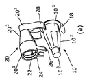
以下の実施形態では、針先格納容器は、比較的大きな径の部分101であって、例えば図1(a)、図5(a)及び図10(b)にみられるように、比較的小さな径の閉鎖先端部103とそれ自体結合される円錐台形部分102と結合された、比較的大きな径の部分からなっている。大円筒状部は内部において、その周りに間隔をおいて配置されたスプライン12を有する内側円筒状壁を形成し、スプラインは、針先ハブが針先格納容器との回転不能な係合へと摺動され且つ取り外されることを可能とするように設計されている。この例において、針先は、両頭針を有している(図2(a)を参照)。針先格納容器10は、取り外し可能なホイル18によって封止されている。第1の実施形態において、針先取り外しハウジング20は、別個の工程により、通常異なる材料から形成されるが、針先格納容器10と同様の全体形状及び内部形状を有している。このため、針先取り外しハウジング20は、比較的大きな径の部分201であって、円筒状先端部203とそれ自体結合される円錐台形部分202と結合された、比較的大きな径の部分を有している。大円筒状部201は、内部に、使用済み針先が回転不能な係合へと摺動され得るスプライン22を備えている。大きな径の円筒状部201の開口端部は、内側スナップリブ24であって、完全に押し出されると取り外しハウジング20に使用済み針先をロックするように構成された内側スナップリブ24を備えている。
In the following embodiments, the needle point containment is a
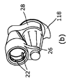
大円筒状部201及び小円筒状部203から横方向への突出はそれぞれ、小クリップ部26及び大クリップ部28であって、図1(b)に示されているように針先格納容器と取り外しハウジングとをともに留めることが可能な弾力性クリップ凹部をそれぞれ形成する、小クリップ部及び大クリップ部である。留める動作は、恒久的であるか又は可逆的であってもよい。
Each projecting from the large
ここで図2を参照すると、第2の実施形態の多くの特徴は、第1の実施形態の特徴と同様であり、同様の参照符号が付されているが、100だけ加算されている。この実施形態において、針先取り外しハウジングは、横方向に延びる小環状部126及び大環状部128をそれぞれ備えている。針先格納容器は、小さな径の円筒状部1103及び大きな径の円筒状部1101の外面に、小さな径のスナップリング130、大きな径のスナップリング132を備えている。針先格納容器及び針先取り外しハウジングは、これらを図2(a)の位置に配置し、その後、図2(b)にみられるように環状部126及び128を通してリブ130、132を嵌め込んで留めるようにすることによって、一緒に組み立てることができる。
Referring now to FIG. 2, many of the features of the second embodiment are similar to those of the first embodiment and are given the same reference numerals, but are incremented by 100. In this embodiment, the needle tip removal housing includes a small
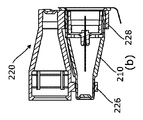
ここで図3を参照すると、第3の実施形態の多くの特徴は、第2の実施形態の特徴と同様であり、同様の参照符号が付されているが、100だけ加算されている。この実施形態において、針先格納容器210の小さな径の部分及び大きな径の部分は、環状リブ230及び232とともに形成されている。針先格納容器210及び針先取り外しハウジング220は、図3に示されているように配置され、環状リブ230及び232が接するとともに、針先取り外しハウジング220上のリング226、228の内側円筒面に達するように、一緒に押し出される。その後、超音波溶着(溶接)工程を利用し、周囲環状部226、228とともにリブ230及び232を溶解又は溶融させて、針先格納容器と針先取り外しハウジングをともに恒久的に固定させる。
Referring now to FIG. 3, many of the features of the third embodiment are similar to those of the second embodiment and are given the same reference numerals, but are incremented by 100. In this embodiment, the small diameter portion and the large diameter portion of the needle
ここで図4を参照すると、第4の実施形態の多くの特徴は、第3の実施形態の特徴と同様であり、同様の参照符号が付されているが、100だけ加算されている。この実施形態において、針先格納容器310は、その小さな径の部分及び大きな径の部分において、それぞれ、環状凹部330及び332を備えている。針先取り外しハウジング320は、第4の実施形態と同一であり、針先格納容器及び針先取り外しハウジングは、溝330及び332に接着剤を塗布し、その後、図4(b)に示されているようにこれらの2つを一緒に組み立てることによって、一緒に組み立てられる。
Referring now to FIG. 4, many features of the fourth embodiment are similar to those of the third embodiment and are given the same reference numerals, but are incremented by 100. In this embodiment, the needle
ここで図5を参照すると、この実施形態では、針先格納容器410は、先の実施形態の針先格納容器と同様であり、上述した種類の針先を収容し、ホイル418によって封止され、針先格納容器の大円筒状部の開口端部に設けられたフランジ422から横方向に延びたタブ420を備えている。フランジ422は、ホイル418がヒートシールされた平面状の半径方向面を備えている。タブ420は、針先格納容器410の主要部分と同一の成形工程により一体的に形成される。
Referring now to FIG. 5, in this embodiment, the needle
この実施形態において、針先取り外しハウジングは、その内容が参照により本明細書に援用される国際公開公報第2005/102424号に記載されているように、本出願人による既存のUniGuard(登録商標)装置に基づいている。針先取り外しハウジング426は、輪郭に概して一致する開口部428を有し、針先のハブ414及び針416が横方向に挿入されると、針先のハブ及び針を収容するように構成されている。開口部には、U字型クレードル部428であって、横方向に挿入されると針ハブが嵌る2つの支台430をそばに有したU字型クレードル部が含まれている。針ハブは、その十分な定位置にあると、回転不能に係合するように、U字型部分428の内側でスプライン(図示せず。)に係合する。必要に応じて、ユーザが最初に針ハブを横方向に挿入して、その後、十分な定位置まで軸線方向に(針の方向に)押し出すという、2段階の係合動作であってもよい。この後者の位置では、針ハブは、軸線方向の逆の動作に対して保持されるように、舌部432から離して留めることができる。特に、図5(a)及び5(d)で見られるように、針取り外しハウジング426は、凹部434を備え、その中で、針先格納容器のフランジ上のタブ420が不可逆的に留められている。凹部434内にタブ420を留めることによって、針先取り外しハウジング426の下面に対して緊密に針先格納容器が保持され、その部分は支持体436、438に載置され、針ハウジングの小さな径の端部は、針先格納容器と針先取り外しハウジングをともに確実に保持するように、突部442を留める縁部内に皿状部440を備えている。
In this embodiment, the needle tip removal housing is an existing UniGuard® by the applicant, as described in WO 2005/102424, the contents of which are incorporated herein by reference. Based on the device. The needle tip removal housing 426 has an
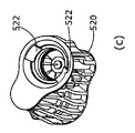
ここで図6及び7の実施形態を参照すると、ここでは、二個取成形法(two-shot)又はオーバーモールド成形法を用いて、最初に、先の実施形態の針先格納容器と同様の形態の針先格納容器510を形成し、その後、封止した針先を装着し、次いで滅菌することができる。第2の成形工程において、異なるプラスチック材料を用いて、針先取り外しハウジング520は、主針先収容部であって、針先格納容器を囲み連結する一体型フレーム構造を備えた主針先収容部を有するように成形される。針先取り外し部には、針先取り外し部に一旦挿入された使用済み針先が外れるのを防止するように、可撓性タブ522が含まれ得る。他の実施形態と同様に、針先取り外し部は、使用済み針先を収容するように回転不能に構成された凹部を有している。図6において、針先格納容器を囲む主フレーム要素は、概して長手方向に延びているが、図7の配置では、主フレーム要素は、概して円周方向に延びている。
Referring now to the embodiment of FIGS. 6 and 7, here, using a two-shot or overmolding method, the first is similar to the needle tip storage container of the previous embodiment. Formed needle
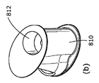
ここで図8を参照すると、この実施形態では、針先取り外しハウジング810は、前述したように使用済み針先を収容するように回転不能に構成された針先取り外し部812を備えている。針先取り外し部に隣接して、針先格納容器をスナップフィットによって収容するように構成された凹状部814が存在している。したがって、前述したように、針先取り外しハウジング及び針先格納容器は、別々に形成し、その後、一緒に組み立て最終製品を形成することができる。
Referring now to FIG. 8, in this embodiment, the needle
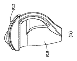
ここで図9〜11に示されている実施形態を参照すると、ここでは、針先格納及び取り外し装置は、針先格納容器内で針先を組み立て、前述したように無菌一次包装を提供し、次いで、組立品を廃棄システム900に係合することにより製造され、これによって、廃棄システムのより広い材料を選択することができ、加工コストを削減することができる。針廃棄システムは、針先格納容器へアクセスすることが可能な開位置及び針先格納容器へのアクセスが妨げられる閉位置から移動可能な蓋912を有したハウジング910を備えている。器具は、閉鎖動作のあらゆる適切な形態を用いることができるが、図9〜11の実施形態では、円弧状の摺動動作を用いて、図9(a)に示されている開位置から、図9(b)に示されている閉位置にカバーを摺動させることができる。カバーには、閉位置にカバーをラッチするラッチ機構914、916が含まれている。
Referring now to the embodiment shown in FIGS. 9-11, where the needle tip storage and removal device assembles the needle tip within the needle tip storage container and provides sterile primary packaging as described above, The assembly is then manufactured by engaging the
ここで図10を参照すると、ハウジング910は、針先格納容器918を収容するように構成された凹部916を有している。針先格納容器は、凹部内で締まり嵌めされていても、又は適所に留められていてもよい。特に図10(a)に見られるように、凹部は、内側半径方向階段状リブ920であって、針先格納容器の外側で構造体922と協働してその間における回転を防止する内側半径方向階段状リブを備えている。カバー912をその閉位置にロックするラッチ機構は、カバー916上の対応する可撓性歯と協働する歯914をハウジングに備えている。図10の装置は、針格納容器918が凹部に係合されたときに針格納容器918のホイル922がカバー912の閉位置への移動を妨げ、これにより一度ホイルが取り除かれるとカバーのみが閉位置へと摺動され得るように設計されている。
Referring now to FIG. 10, the
再び図10(a)を参照すると、半径方向リブ920は、内側に階段状になっており、針先格納容器が、何らかの形で廃棄システムから取り外す必要がある場合に、フェールセーフ構造として、凹部が回転不能に針ハブ926を摺動可能に収容することができるとともに、内側階段状リブ920がハブにおいてスプライン928と協働するように構成されている。
Referring again to FIG. 10 (a), the
図11を参照すると、装置が供給される場合には、カバー912は、その開位置にあり、ホイルシール922のタブによって閉位置に移動されるのが防止される。ユーザは、ホイルシール922を取り外し、その後、ペンを挿入し、ペンを針にねじ留めし針をまとめることによって、装置を準備する。その後、ユーザは、装置からペンを後退させ、次いで、内側針シールド930を取り外し、注入の準備ができた針を露出させる(図11(e))。注入後、ユーザは、針ハブを針格納容器に戻し、ペンを回して外す。これは、図11(f)に見ることができる。一次包装がない場合に、追加機能として、ペンを廃棄システムに深く挿入し、針ハブと半径方向スプラインとを係合することができる。ペンが取り外されると、カバーは本体周囲を摺動し、ハウジング上の歯から離れて留められたカバー上の歯で針を被覆し、適所に針をロックすることができる。そして、使用済み針は、廃棄される準備ができた安全な状態にある。
Referring to FIG. 11, when the device is supplied, the
Claims (31)
無菌環境で針先を収容し且つ開放可能な封止要素によって封止される所定の形成工程で形成された格納隔室と、
使用済み針先を収容するための針取り外しハウジングであって別の形成工程で形成され且つ前記格納隔室に又は前記格納隔室の周りに接続された針取り外しハウジングと、を有する、針先格納及び取り外し装置。 A needle tip storage and removal device for use with a needle tip comprising a needle hub and a needle extending axially from the needle hub,
A storage compartment formed in a predetermined forming step that is sealed by a releasable sealing element that accommodates the needle tip in an aseptic environment; and
A needle removal housing for receiving a used needle tip, the needle removal housing having a needle removal housing formed in a separate forming step and connected to or around the storage compartment And removal device.
1つの工程段階において格納隔室を形成することと、
別の工程段階において取り外し器具を形成することと、
前記格納隔室及び前記取り外し器具を共に組み立てることと、を含む方法。 A method of manufacturing a needle tip storage and removal device comprising:
Forming a containment compartment in one process step;
Forming the removal implement in a separate process step;
Assembling the storage compartment and the removal implement together.
超音波溶着、
機械的連結、
熱溶着及び
接着の、
少なくとも1つの方法によって、前記格納隔室に対して連結される、請求項22から27のいずれか一項に記載の方法。 The removal implement is
Ultrasonic welding,
Mechanical linkage,
Heat welding & bonding,
28. A method according to any one of claims 22 to 27, coupled to the storage compartment by at least one method.
Applications Claiming Priority (3)
| Application Number | Priority Date | Filing Date | Title |
|---|---|---|---|
| GB1306601.4A GB2512913A (en) | 2013-04-11 | 2013-04-11 | Needle tip storage and removal device and methods of manufacture thereof |
| GB1306601.4 | 2013-04-11 | ||
| PCT/GB2014/051125 WO2014167340A1 (en) | 2013-04-11 | 2014-04-10 | Needle tip storage and removal device and methods of manufacture thereof |
Related Child Applications (1)
| Application Number | Title | Priority Date | Filing Date |
|---|---|---|---|
| JP2019002814A Division JP2019088819A (en) | 2013-04-11 | 2019-01-10 | Needle tip storage and removal device and methods of manufacture thereof |
Publications (2)
| Publication Number | Publication Date |
|---|---|
| JP2016518905A true JP2016518905A (en) | 2016-06-30 |
| JP2016518905A5 JP2016518905A5 (en) | 2017-05-25 |
Family
ID=48537102
Family Applications (2)
| Application Number | Title | Priority Date | Filing Date |
|---|---|---|---|
| JP2016507062A Ceased JP2016518905A (en) | 2013-04-11 | 2014-04-10 | Needle tip storage and removal device and manufacturing method thereof |
| JP2019002814A Pending JP2019088819A (en) | 2013-04-11 | 2019-01-10 | Needle tip storage and removal device and methods of manufacture thereof |
Family Applications After (1)
| Application Number | Title | Priority Date | Filing Date |
|---|---|---|---|
| JP2019002814A Pending JP2019088819A (en) | 2013-04-11 | 2019-01-10 | Needle tip storage and removal device and methods of manufacture thereof |
Country Status (9)
| Country | Link |
|---|---|
| US (1) | US20160303331A1 (en) |
| EP (2) | EP3345636B1 (en) |
| JP (2) | JP2016518905A (en) |
| KR (1) | KR20160020412A (en) |
| CN (1) | CN105283208A (en) |
| GB (1) | GB2512913A (en) |
| MX (1) | MX2015014247A (en) |
| MY (1) | MY175894A (en) |
| WO (1) | WO2014167340A1 (en) |
Families Citing this family (24)
| Publication number | Priority date | Publication date | Assignee | Title |
|---|---|---|---|---|
| WO2016087187A1 (en) * | 2014-12-01 | 2016-06-09 | Novo Nordisk A/S | Needle assembly with cap for safe disposal of a pen needle |
| USD804023S1 (en) | 2016-04-14 | 2017-11-28 | Becton, Dickinson And Company | Pen needle inner shield |
| USD787669S1 (en) | 2016-04-14 | 2017-05-23 | Becton, Dickinson And Company | Pen needle outer cover |
| USD787053S1 (en) | 2016-04-14 | 2017-05-16 | Becton, Dickinson And Company | Pen needle inner shield |
| USD825749S1 (en) | 2016-04-14 | 2018-08-14 | Becton, Dickinson And Company | Pen needle outer cover |
| USD787054S1 (en) | 2016-04-14 | 2017-05-16 | Becton, Dickinson And Company | Pen needle hub |
| US20180015224A1 (en) | 2016-07-13 | 2018-01-18 | California Institute Of Technology | Dampers and Methods for Performing Measurements in an Autoinjector |
| USD938022S1 (en) | 2016-08-10 | 2021-12-07 | Owen Mumford Limited | Safety pen needle |
| US10792438B2 (en) | 2016-12-13 | 2020-10-06 | Becton, Dickinson And Company | Safety needle devices |
| US10729843B2 (en) | 2016-12-12 | 2020-08-04 | Becton, Dickinson And Company | Dual packaging for fill needle and safety needle |
| US11173253B2 (en) | 2016-12-12 | 2021-11-16 | Becton, Dickinson And Company | Packaging for safety needle |
| US11147910B2 (en) | 2016-12-12 | 2021-10-19 | Becton, Dickinson And Company | Packaging for safety needle |
| US20180161491A1 (en) * | 2016-12-12 | 2018-06-14 | Becton, Dickinson And Company | Packaging For Safety Needle |
| US11103651B2 (en) | 2016-12-13 | 2021-08-31 | Beckon, Dickinson and Company | Safety needle devices |
| US10661026B2 (en) | 2016-12-13 | 2020-05-26 | Becton, Dickinson And Company | Safety needle device |
| US10589036B2 (en) | 2016-12-13 | 2020-03-17 | Becton, Dickinson And Company | Safety needle device |
| US20180221590A1 (en) * | 2017-02-08 | 2018-08-09 | Rajpal SUBHASH | Apparatus for safely detaching a hypodermic needle from a syringe |
| JP7089019B2 (en) | 2018-03-16 | 2022-06-21 | テルモ株式会社 | Intracutaneous needle and its package and injection device |
| KR101940085B1 (en) * | 2018-03-29 | 2019-01-18 | (주)풍림파마텍 | Syringe cap for preventing reuse |
| USD914208S1 (en) | 2019-06-14 | 2021-03-23 | Owen Mumford Limited | Syringe component |
| TWD206925S (en) | 2019-06-14 | 2020-09-01 | 英商歐恩.曼佛爾德股份有限公司 | Syringe |
| JP2023516352A (en) * | 2020-03-05 | 2023-04-19 | ベクトン・ディキンソン・アンド・カンパニー | packaging for safety needles |
| USD959651S1 (en) | 2020-04-08 | 2022-08-02 | Owen Mumford Limited | Medical instrument |
| USD972745S1 (en) | 2020-05-07 | 2022-12-13 | Owen Mumford Limited | Testing device |
Citations (8)
| Publication number | Priority date | Publication date | Assignee | Title |
|---|---|---|---|---|
| US5084027A (en) * | 1991-07-19 | 1992-01-28 | Bernard Daniel H | Needle cover with safety disposal chamber |
| JPH0866475A (en) * | 1994-08-16 | 1996-03-12 | Becton Dickinson & Co | Needle dispenser for medication pen |
| US5554129A (en) * | 1994-11-28 | 1996-09-10 | Stevenson; John A. | Safety cap and hub for medical instruments |
| JP2003533291A (en) * | 2000-05-15 | 2003-11-11 | アレス トレーディング ソシエテ アノニム | A device for separating the connection end of a hypodermic needle from the tip of the injection device |
| WO2005102424A1 (en) * | 2004-04-27 | 2005-11-03 | Owen Mumford Limited | Apparatus for removing needle assembly |
| US20060032769A1 (en) * | 2004-08-14 | 2006-02-16 | Erickson Thomas E | Sharps container for (I) safe disposal and storage of a single used medical pen needle and/or (II) safe storage and dispensing of a single unused medical pen needle |
| JP2007503871A (en) * | 2003-08-28 | 2007-03-01 | スミスズ メディカル エイエスディー インコーポレイテッド | Needle protection assembly |
| JP2009536539A (en) * | 2006-05-11 | 2009-10-15 | オーウェン マンフォード リミテッド | Needle tip storage and removal instrument |
Family Cites Families (15)
| Publication number | Priority date | Publication date | Assignee | Title |
|---|---|---|---|---|
| GB967302A (en) * | 1960-07-28 | 1964-08-19 | Gillette Industries Ltd | Improvements in packaging |
| US4673094A (en) * | 1986-09-22 | 1987-06-16 | Universal Symetrics Corporation | Large stub spout bottles and mated combination unit |
| US4836373A (en) * | 1988-10-03 | 1989-06-06 | Boris Goldman | Hypodermic syringe and cover handling device |
| US5347078A (en) * | 1992-09-04 | 1994-09-13 | Eckels John F | Syringe needle disposal apparatus |
| EP0799065B1 (en) * | 1994-07-19 | 2001-11-28 | Novo Nordisk A/S | Needle magazine |
| US6315113B1 (en) * | 1997-06-30 | 2001-11-13 | Richard B. Britton | Chemical disposal of medical syringe needles and other hazardous sharps |
| US6346094B2 (en) * | 1998-09-28 | 2002-02-12 | Becton, Dickinson And Company | Pen needle magazine |
| WO2002011797A1 (en) * | 2000-08-03 | 2002-02-14 | Novo Nordisk A/S | A needle magazine |
| US20040173488A1 (en) * | 2002-11-07 | 2004-09-09 | Griffin Carl E. | Disposal device for sampling materials |
| EP1741459A1 (en) * | 2005-07-08 | 2007-01-10 | Biofluid Systems S.A. | Multifunction device for syringe needles |
| US20110071475A1 (en) * | 2009-09-18 | 2011-03-24 | Becton, Dickinson And Company | Outer cover of a pen needle for a drug delivery pen |
| RU2012141542A (en) * | 2010-03-05 | 2014-04-10 | Ново Нордиск А/С | NEEDLE CARTRIDGE CONSISTING OF TWO TURNS RELATED TO OTHER OTHER PARTS |
| US8464896B2 (en) * | 2011-02-10 | 2013-06-18 | Brian Beary | Straw holder for beverage cup or beverage cup lid |
| EP2522380A1 (en) * | 2011-05-12 | 2012-11-14 | Sanofi-Aventis Deutschland GmbH | Needle assembly storage array |
| GB2497735A (en) * | 2011-12-16 | 2013-06-26 | Owen Mumford Ltd | Needle Tip Storage and Removal Device |
-
2013
- 2013-04-11 GB GB1306601.4A patent/GB2512913A/en not_active Withdrawn
-
2014
- 2014-04-10 MX MX2015014247A patent/MX2015014247A/en unknown
- 2014-04-10 EP EP18158443.4A patent/EP3345636B1/en active Active
- 2014-04-10 KR KR1020157032386A patent/KR20160020412A/en not_active Application Discontinuation
- 2014-04-10 WO PCT/GB2014/051125 patent/WO2014167340A1/en active Application Filing
- 2014-04-10 US US14/783,630 patent/US20160303331A1/en not_active Abandoned
- 2014-04-10 EP EP14724128.5A patent/EP2996739B1/en active Active
- 2014-04-10 CN CN201480032938.XA patent/CN105283208A/en active Pending
- 2014-04-10 MY MYPI2015002527A patent/MY175894A/en unknown
- 2014-04-10 JP JP2016507062A patent/JP2016518905A/en not_active Ceased
-
2019
- 2019-01-10 JP JP2019002814A patent/JP2019088819A/en active Pending
Patent Citations (8)
| Publication number | Priority date | Publication date | Assignee | Title |
|---|---|---|---|---|
| US5084027A (en) * | 1991-07-19 | 1992-01-28 | Bernard Daniel H | Needle cover with safety disposal chamber |
| JPH0866475A (en) * | 1994-08-16 | 1996-03-12 | Becton Dickinson & Co | Needle dispenser for medication pen |
| US5554129A (en) * | 1994-11-28 | 1996-09-10 | Stevenson; John A. | Safety cap and hub for medical instruments |
| JP2003533291A (en) * | 2000-05-15 | 2003-11-11 | アレス トレーディング ソシエテ アノニム | A device for separating the connection end of a hypodermic needle from the tip of the injection device |
| JP2007503871A (en) * | 2003-08-28 | 2007-03-01 | スミスズ メディカル エイエスディー インコーポレイテッド | Needle protection assembly |
| WO2005102424A1 (en) * | 2004-04-27 | 2005-11-03 | Owen Mumford Limited | Apparatus for removing needle assembly |
| US20060032769A1 (en) * | 2004-08-14 | 2006-02-16 | Erickson Thomas E | Sharps container for (I) safe disposal and storage of a single used medical pen needle and/or (II) safe storage and dispensing of a single unused medical pen needle |
| JP2009536539A (en) * | 2006-05-11 | 2009-10-15 | オーウェン マンフォード リミテッド | Needle tip storage and removal instrument |
Also Published As
| Publication number | Publication date |
|---|---|
| KR20160020412A (en) | 2016-02-23 |
| EP2996739B1 (en) | 2018-05-30 |
| EP2996739A1 (en) | 2016-03-23 |
| EP3345636A1 (en) | 2018-07-11 |
| WO2014167340A1 (en) | 2014-10-16 |
| EP3345636B1 (en) | 2020-05-27 |
| MX2015014247A (en) | 2016-03-01 |
| GB201306601D0 (en) | 2013-05-29 |
| CN105283208A (en) | 2016-01-27 |
| US20160303331A1 (en) | 2016-10-20 |
| JP2019088819A (en) | 2019-06-13 |
| GB2512913A (en) | 2014-10-15 |
| MY175894A (en) | 2020-07-14 |
Similar Documents
| Publication | Publication Date | Title |
|---|---|---|
| JP2016518905A (en) | Needle tip storage and removal device and manufacturing method thereof | |
| US11103634B2 (en) | Method of storing both new and used pen needles | |
| JP7154254B2 (en) | medical cannula package | |
| RU2709390C2 (en) | Device for needle protection, syringe containing such device, and method for manufacturing pre-filled syringes with attached needle | |
| US20150374440A1 (en) | Shipping Container Integrating A Sharps Disposal Container With A New Product Storage Container | |
| KR101433829B1 (en) | A case for injection needle | |
| CN111032131B (en) | Intradermal needle, package thereof, and injection device | |
| CA3096168A1 (en) | Pen needle storage | |
| US20180169340A1 (en) | Method for producing at least one reservoir assembly, injectable-product reservoir assembly for an injection pen and injection pen equipped with such an assembly | |
| US10729854B2 (en) | Housing for mounting a container on an injection pen, assembly forming an injectable product reservoir for an injection pen and injection pen equipped with such an assembly | |
| CN112173344A (en) | Double-layer packaging for objects intended to maintain sterility | |
| CN109125857B (en) | Pen needle multi-carrier injection system | |
| CA3134322A1 (en) | Pen needle magazine |
Legal Events
| Date | Code | Title | Description |
|---|---|---|---|
| A521 | Request for written amendment filed |
Free format text: JAPANESE INTERMEDIATE CODE: A523 Effective date: 20170405 |
|
| A621 | Written request for application examination |
Free format text: JAPANESE INTERMEDIATE CODE: A621 Effective date: 20170405 |
|
| A521 | Request for written amendment filed |
Free format text: JAPANESE INTERMEDIATE CODE: A523 Effective date: 20170802 |
|
| A521 | Request for written amendment filed |
Free format text: JAPANESE INTERMEDIATE CODE: A821 Effective date: 20170802 |
|
| A977 | Report on retrieval |
Free format text: JAPANESE INTERMEDIATE CODE: A971007 Effective date: 20180209 |
|
| A131 | Notification of reasons for refusal |
Free format text: JAPANESE INTERMEDIATE CODE: A131 Effective date: 20180220 |
|
| A601 | Written request for extension of time |
Free format text: JAPANESE INTERMEDIATE CODE: A601 Effective date: 20180518 |
|
| A521 | Request for written amendment filed |
Free format text: JAPANESE INTERMEDIATE CODE: A523 Effective date: 20180615 |
|
| A02 | Decision of refusal |
Free format text: JAPANESE INTERMEDIATE CODE: A02 Effective date: 20180911 |
|
| A521 | Request for written amendment filed |
Free format text: JAPANESE INTERMEDIATE CODE: A523 Effective date: 20190110 |
|
| A911 | Transfer to examiner for re-examination before appeal (zenchi) |
Free format text: JAPANESE INTERMEDIATE CODE: A911 Effective date: 20190121 |
|
| A912 | Re-examination (zenchi) completed and case transferred to appeal board |
Free format text: JAPANESE INTERMEDIATE CODE: A912 Effective date: 20190201 |
|
| A521 | Request for written amendment filed |
Free format text: JAPANESE INTERMEDIATE CODE: A523 Effective date: 20200409 |
|
| A045 | Written measure of dismissal of application [lapsed due to lack of payment] |
Free format text: JAPANESE INTERMEDIATE CODE: A045 Effective date: 20201027 |