JP2016514581A - Sheet - Google Patents
Sheet Download PDFInfo
- Publication number
- JP2016514581A JP2016514581A JP2016506789A JP2016506789A JP2016514581A JP 2016514581 A JP2016514581 A JP 2016514581A JP 2016506789 A JP2016506789 A JP 2016506789A JP 2016506789 A JP2016506789 A JP 2016506789A JP 2016514581 A JP2016514581 A JP 2016514581A
- Authority
- JP
- Japan
- Prior art keywords
- seat
- connection point
- distance
- backrest
- spring
- Prior art date
- Legal status (The legal status is an assumption and is not a legal conclusion. Google has not performed a legal analysis and makes no representation as to the accuracy of the status listed.)
- Ceased
Links
Images


Classifications
-
- A—HUMAN NECESSITIES
- A61—MEDICAL OR VETERINARY SCIENCE; HYGIENE
- A61G—TRANSPORT, PERSONAL CONVEYANCES, OR ACCOMMODATION SPECIALLY ADAPTED FOR PATIENTS OR DISABLED PERSONS; OPERATING TABLES OR CHAIRS; CHAIRS FOR DENTISTRY; FUNERAL DEVICES
- A61G5/00—Chairs or personal conveyances specially adapted for patients or disabled persons, e.g. wheelchairs
- A61G5/10—Parts, details or accessories
- A61G5/1056—Arrangements for adjusting the seat
- A61G5/1067—Arrangements for adjusting the seat adjusting the backrest relative to the seat portion
-
- A—HUMAN NECESSITIES
- A47—FURNITURE; DOMESTIC ARTICLES OR APPLIANCES; COFFEE MILLS; SPICE MILLS; SUCTION CLEANERS IN GENERAL
- A47C—CHAIRS; SOFAS; BEDS
- A47C7/00—Parts, details, or accessories of chairs or stools
- A47C7/36—Support for the head or the back
- A47C7/40—Support for the head or the back for the back
- A47C7/44—Support for the head or the back for the back with elastically-mounted back-rest or backrest-seat unit in the base frame
- A47C7/446—Support for the head or the back for the back with elastically-mounted back-rest or backrest-seat unit in the base frame with fluid springs
-
- A—HUMAN NECESSITIES
- A61—MEDICAL OR VETERINARY SCIENCE; HYGIENE
- A61G—TRANSPORT, PERSONAL CONVEYANCES, OR ACCOMMODATION SPECIALLY ADAPTED FOR PATIENTS OR DISABLED PERSONS; OPERATING TABLES OR CHAIRS; CHAIRS FOR DENTISTRY; FUNERAL DEVICES
- A61G5/00—Chairs or personal conveyances specially adapted for patients or disabled persons, e.g. wheelchairs
- A61G5/10—Parts, details or accessories
Abstract
この発明は、シートと、シートを車椅子に取り付けるためのシート接続手段を有するシートを備えた車椅子に関連するもので、シートはシート枠(101)と、ピボット手段(105)を介してシート枠に旋回可能に接続されている背もたれ(103)と、及び第1接続点(109)とシート枠の近くの第2接続点(111)で背もたれに接続されているスプリング手段(107)とを有し、第2接続点(111)とピボット手段(105)は距離Cが空けられている。シートは距離Cを変更するようになっている調節手段(113)を備えている。結果としてスプリング手段のテンションは容易に調節でき、それによりシートは異なる体重と力に適応出来る。従ってスプリングを異なるテンションのスプリングに取り換える必要がない。【選択図】図2The present invention relates to a wheelchair including a seat and a seat having seat connecting means for attaching the seat to the wheelchair. The seat is attached to the seat frame via the seat frame (101) and the pivot means (105). A backrest (103) connected pivotably; and a spring means (107) connected to the backrest at a first connection point (109) and a second connection point (111) near the seat frame. The second connection point (111) and the pivot means (105) are separated by a distance C. The seat is provided with adjusting means (113) adapted to change the distance C. As a result, the tension of the spring means can be easily adjusted, so that the seat can adapt to different weights and forces. Therefore, it is not necessary to replace the spring with a spring having a different tension. [Selection] Figure 2
Description
この発明は、車椅子用のシートとそのシートを備えた車椅子に関する。 The present invention relates to a wheelchair seat and a wheelchair provided with the seat.
車椅子の身体障害者の快適のために、車いすに、背もたれに対する急で強い随意的または不随意的な人の動きのエネルギーを吸収することが出来る、ダイナミックなリクライニング出来る背もたれを備えることは好都合である。 For the comfort of disabled persons in wheelchairs, it is advantageous to have a wheelchair with a dynamic reclining backrest that can absorb the energy of a sudden and strong voluntary or involuntary movement of the person against the backrest .
背もたれは、また治療的な理由で、弾力性があり、けいれん、つまり突然の制御出来ない動き等を起こす傾向のあるユーザーに、車椅子を使っている時に怪我をさせないようにする必要がある。 The backrest must also be elastic for therapeutic reasons and should not hurt users who are prone to convulsions, that is, suddenly uncontrollable movements, when using the wheelchair.
そのような動きは、背もたれを、よりリクライニングさせる方向に拡げる傾向がある。エネルギーが吸収された後は、背もたれは人を起き上がった座位に戻すことが出来るべきである。 Such movements tend to spread the backrest in a more reclining direction. After the energy is absorbed, the backrest should be able to return the person to the sitting position.
そのような車椅子のシートは、“X:panda”(登録商標)として知られる製品を有する出願人により、利用可能となっている。車椅子のシートは、先に記述した背もたれを広げる動きのエネルギーを吸収するために、背もたれとシートの間に、動ける形で置かれたガススプリングを有する、リクライニング出来る背もたれを備えている。 Such wheelchair seats are made available by applicants with a product known as “X: panda” ®. The wheelchair seat has a reclining backrest with a gas spring placed in a movable manner between the backrest and the seat to absorb the energy of the movement of spreading the backrest as described above.
ガススプリングを組み込むシート/背もたれ構造物は、US2、018,825により知られている。ガススプリングは、固定した(しかし選択可能)な位置に配置され、追加された快適さをユーザーに提供する。 A seat / backrest structure incorporating a gas spring is known from US 2,018,825. The gas spring is placed in a fixed (but selectable) position to provide the user with added comfort.
様々な体重と力の人に応じるために、ガススプリングは既定のレートを有する様々なガススプリングの中から選ばれる。まだ成長している障害のある子供の場合には、背もたれに掛かる力は、子供の体重と身長の増加に伴い増加するので、ガススプリングは、車椅子の寿命の間に頻繁に取り換えなければならないであろう。従って、あるサイズのガススプリング(あるテンション)は、シートに対して限られた期間においてのみ最も適している。 In order to accommodate people of different weights and strengths, the gas springs are selected from a variety of gas springs having a predetermined rate. In the case of a disabled child who is still growing, the force on the backrest increases with the weight and height of the child, so gas springs must be replaced frequently during the life of the wheelchair. I will. Thus, certain sizes of gas springs (some tensions) are most suitable only for a limited period of time on the sheet.
この発明の目的は、まだ成長過程にある障害のある子供に適した車椅子のシートを提供することにある。 An object of the present invention is to provide a wheelchair seat suitable for a disabled child who is still growing.
この発明によれば、これは車椅子にシートを取り付けるためのシート取り付け手段を有するシートによって達成され、当該車いすはシート枠、ピボット(旋回)出来る形でピボット手段を通じてシート枠に接続されている背もたれ、ならびに第1接続点で背もたれに、及びシート枠の近くで第2接続点に接続されているスプリング手段から構成される。第2接続点とピボット手段の間は距離Cだけ開いており、シートは距離Cを変更するために適応された調節手段(113)で構成されている。 According to the invention, this is achieved by a seat having seat attachment means for attaching the seat to the wheelchair, the wheelchair being seat frame, a pivotable backrest connected to the seat frame through the pivot means, And spring means connected to the backrest at the first connection point and to the second connection point near the seat frame. The distance between the second connection point and the pivot means is open by a distance C, and the seat is composed of adjusting means (113) adapted to change the distance C.
従って、スプリング手段のテンションは、容易に調節でき、そしてその結果、シートは異なる体重と力に適応できる。従って、異なるテンションを有するスプリングに交換する必要はない。 Thus, the tension of the spring means can be easily adjusted, so that the seat can adapt to different weights and forces. Therefore, it is not necessary to replace the spring with a different tension.
ある実施形態では、調節手段は、第2接続点の位置を置き変えることで、距離Cを変更するために適用適応されている。従って、調節機構は1つの接続点に加えられることが出来、調節機構の実行と取り扱いを単純にする。 In an embodiment, the adjusting means is adapted to change the distance C by replacing the position of the second connection point. Thus, the adjustment mechanism can be added to one connection point, simplifying the implementation and handling of the adjustment mechanism.
ある実施形態では、第2接続点はガイドアームに接続され、そして第2接続点の位置は、そして結果としての距離Cは、接続点をガイドアームに沿って滑らせることで、調節可能である。ガイドは、第2接続点は調節している間の対応する調節方向以外の全ての方向における固定を保証し、それによって調節は取扱が容易である。 In an embodiment, the second connection point is connected to the guide arm, and the position of the second connection point and the resulting distance C is adjustable by sliding the connection point along the guide arm. . The guide ensures that the second connection point is fixed in all directions except the corresponding adjustment direction while adjusting, so that the adjustment is easy to handle.
ある実施形態では、ガイドアームはシート枠に取り付けられ、そして第2接続点はスライド出来る形で、ガイドアームに沿ってスライドさせるために、ガイドアームの回りに接続されている。これは非常にシンプルで効果的な解決方法であることが実証されている。 In some embodiments, the guide arm is attached to the seat frame and the second connection point is slidably connected around the guide arm for sliding along the guide arm. This has proven to be a very simple and effective solution.
ある実施形態では、ガイドアームはスプリング手段の方向に対して、概ね垂直方向に延びている。従ってテンションは特に調節が容易である。 In certain embodiments, the guide arm extends generally perpendicular to the direction of the spring means. Therefore, the tension is particularly easy to adjust.
ある実施形態では、シートは、背もたれ及びシート枠に接続されてシートの両側に配置されたスプリング手段を構成している。結果、スプリング手段は、背もたれ面に沿って背もたれの動きのエネルギーを、均等に吸収出来る。 In one embodiment, the seat constitutes spring means connected to the backrest and seat frame and disposed on both sides of the seat. As a result, the spring means can equally absorb the energy of the movement of the backrest along the backrest surface.
ある実施形態では、シートは、接続点の間の実際の距離Cを示す目視指示器を構成している。従って、特別な設定を、例えば、前回の設定に従って設定するまたは、同じテンションで両側を設定するなどを、参照用として使用出来る。 In one embodiment, the sheet constitutes a visual indicator that indicates the actual distance C between the connection points. Therefore, a special setting can be used for reference, for example, setting according to the previous setting or setting both sides with the same tension.
ある実施形態では、シートは、距離Cをロックし、その結果、予め決められた位置に第2接続点をロックするための、ロック手段を構成している。それによって、調節する各々の時に、正確に同じ位置を確実にすることが出来る。 In an embodiment, the seat constitutes a locking means for locking the distance C and consequently locking the second connection point in a predetermined position. Thereby, exactly the same position can be ensured at each adjustment.
この発明は、また、車椅子のシートの背もたれの弾力性を調節する方法を目指していて、シートは、シートを車椅子に取り付けるためのシート接続手段を有していて、その接続手段は、
―シート枠(101)、
―背もたれ(103)、ここで背もたれはピボット出来る形で、ピボット手段(105)を通してシート枠に接続され、及び、
―第1接続点(109)で背もたれに、及びシート枠の近くで第2接続点(111)に接続されたスプリング手段(107、207)であり、第2接続点(111)とピボット手段(105)は距離Cを空けることが出来、シートは、距離Cを調節するために適応された調節手段(113)を構成し、第2接続点(111、211)でガイドアーム(115、215)に接続され、そして第2接続点(111、211)の位置と結果として距離Cは、ガイドアーム(115、215)に沿って第2接続点(111、211)をスライドさせることにより、調節可能で、それにより距離Cが長いほど結果としてスプリングの動きは柔らかくなり、距離Cが短いほど結果としてスプリングの動きは硬くなる前記スプリング手段、から構成される。
The present invention is also aimed at a method for adjusting the elasticity of the backrest of a seat of a wheelchair, and the seat has a seat connecting means for attaching the seat to the wheelchair, and the connecting means includes:
-Sheet frame (101),
The backrest (103), wherein the backrest is pivotable and connected to the seat frame through pivot means (105); and
-Spring means (107, 207) connected to the backrest at the first connection point (109) and to the second connection point (111) near the seat frame, the second connection point (111) and the pivot means ( 105) can make a distance C, and the seat constitutes adjusting means (113) adapted to adjust the distance C, and guide arms (115, 215) at the second connection points (111, 211). And the position of the second connection point (111, 211) and consequently the distance C can be adjusted by sliding the second connection point (111, 211) along the guide arm (115, 215) As a result, the longer the distance C, the softer the spring movement is, and the shorter the distance C, the harder the spring movement, the spring means.
弾力性は、突然の動きの間、ユーザーが動かすことのできる背もたれの能力である。スプリングは、この動きを弱める。ガイドアームの上の取り付け具の位置が調節出来ることにより、“力 × 距離は結果として得られる力に等しい”という原理は、所定のユーザーにとって最も望ましい弾力性(つまり弾性反力)を調整するために、活用される。この調節機能は、より多くの、またはより少ない力を必要とする/望まれる必要性に応じて、この力の調整に役立つ。 Elasticity is the ability of a backrest that a user can move during a sudden movement. The spring weakens this movement. By adjusting the position of the fixture on the guide arm, the principle “force x distance equals the resulting force” is to adjust the most desirable elasticity (ie elastic reaction force) for a given user To be utilized. This adjustment function helps to adjust this force according to the need / desired need for more or less force.
ダブルアクションガススプリング部材によるスプリング手段を更に提供することにより、ガススプリングは、異なるスプリング特性を有する他のガススプリング部材に対して交換することが出来、より広い範囲のユーザーが、単に適切なガススプリングを選択するだけで、シート/車椅子の使用に好適となるようにすることが出来る。 By further providing spring means with a double action gas spring member, the gas spring can be exchanged for other gas spring members with different spring characteristics, allowing a wider range of users to simply use the appropriate gas spring. It is possible to make it suitable for use of a seat / wheelchair by simply selecting.
この発明はさらに、上記に従うシートを備え上述した利点を有する車いすに関する。 The invention further relates to a wheelchair comprising a seat according to the above and having the advantages described above.
この発明を、付属する図面を参照して、下でより詳細に説明する。 The invention will be described in more detail below with reference to the accompanying drawings.
図の説明に於いて、同様のまたは対応する要素は、異なる図面の中で同じ記号表示で提供される。従って、各々の単一の図/実施形態に関連した全ての詳細な説明は提供されない。 In the description of the figures, similar or corresponding elements are provided with the same symbolic designation in different drawings. Accordingly, not all detailed descriptions associated with each single figure / embodiment are provided.
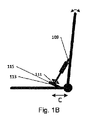
図1A−Dは、この発明の原理を示す。図1Aでは、車椅子に対して取り付けるためのシート100を示す。シートはシート枠101及び背もたれ103を構成し、ここで背もたれはピボット出来る形で、ピボット手段105を通してシート枠に接続されている。シートは、更に、第1接続点109及びシート枠101に近い第2接続点111を通して背もたれとシート枠に接続したスプリング手段107を構成し、ここで、第2接続点111とピボット手段105は距離Cだけ間隔が開いている。ある実施形態におけるスプリング手段は、ガススプリングであり得るが、しかし、別のスプリング要素も同じく使用出来る。シートは、第2接続点111とピボット手段105の間の距離Cを変えるための調節手段(図示せず)を構成する。
1A-D illustrate the principles of the present invention. FIG. 1A shows a
図1Bでは、距離Cを、第2接続点111を移動することにより変えることが出来る実施形態を示す。この実施形態では、第2接続点111はガイドアーム115に接続されている。その結果、調節手段113は接続点を移動可能にし、それにより第2接続点111とピボット手段105の間の距離Cは、第2接続点111をガイドアーム115に沿ってスライドさせることにより、調節可能である。図1Cと図1Dでは、第2接続点111が2つの異なる位置にあり、従って距離Cが変えられている状況が示されている。
FIG. 1B shows an embodiment in which the distance C can be changed by moving the
接続点をスプリングの力の方向とは異なる方向に動かすことにより、スプリング手段の力に抗する必要が無いので、距離の微調整を行うのが容易になる。更に、接続点がそれに沿って移動するガイドアームを有することで、ガイドアームの補助によって、処理の制御が容易である。 By moving the connection point in a direction different from the direction of the force of the spring, it is not necessary to resist the force of the spring means, so that fine adjustment of the distance is facilitated. Further, since the connection point has a guide arm that moves along the connection point, the process can be easily controlled with the assistance of the guide arm.
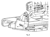
図2は、この発明の1つの実施形態を示し、シート枠に対して第1角度位置にある時に、背もたれの後ろから見た図である。シート200の特定の実施形態は、支持面を備えたシート枠201、ならびに多数の背支持構成要素204を構成する背もたれ203からなる。背もたれとシート枠はピボット手段205でピボット出来る形で接続されている。シートは更に、第1接続点209と第2接続点211を通して背もたれとシート枠に接続されたガススプリング207を構成している。
FIG. 2 shows one embodiment of the present invention, as viewed from the back of the backrest when in the first angular position relative to the seat frame. A particular embodiment of the
シートは、第2接続点211とピボット手段205の間の距離を変えるための調節手段213を構成している。調節手段はシート枠201に取り付けられたガイドアーム215を構成し、そして第2接続点211は、ガイドアームの方向に、ガイドアームをスライドさせるために、ガイドアーム215の回りにスライド出来る形で接続されている。
The seat constitutes adjusting means 213 for changing the distance between the
同様のスプリング手段と調節手段がシートの反対側に配置されている。 Similar spring means and adjustment means are disposed on the opposite side of the seat.
図3は、この発明の実施形態を示し、シート枠に対して第2の角度位置にある背もたれの背後から見た図で、この位置では、ガススプリング207は、背もたれへの負荷(矢印301で表示)のために一緒に力が掛けられている。
FIG. 3 shows an embodiment of the present invention as seen from behind the backrest at a second angular position relative to the seat frame, in which the
図4はこの発明の1つの実施形態を示し、横から見た図であり、第2接続点211がガイドアーム215の一端に動かされ、それにより接続点の間の第1距離が得られ、それによりガススプリングの1つのテンションが得られる。
FIG. 4 shows one embodiment of the invention, seen from the side, where the
図5は、この発明の実施形態を示し、シート枠に対して第2の角度位置にある横から見た図で、この位置では、ガススプリング207は背もたれへの負荷(矢印301で表示)のために一緒に力が掛けられている。
FIG. 5 shows an embodiment of the present invention, and is a view seen from the side at a second angular position with respect to the seat frame. In this position, the
図6は、この発明の1つの実施形態を示し、第2接続点211がガイドアーム215の真ん中に置かれている処を横から見た図で、それにより接続点の間の第2距離が得られ、それによりガススプリングの第2のテンションが得られる。
FIG. 6 shows one embodiment of the present invention, in which the
図7は、この発明の実施形態を示し、シート枠に対して第2の角度位置にある横から見た図で、この位置では、ガススプリング207は背もたれへの負荷(矢印301で表示)のために一緒に力が掛けられている。
FIG. 7 shows an embodiment of the present invention, and is a view seen from the side at a second angular position with respect to the seat frame. In this position, the
図8は、この発明の1つの実施形態及び接続点の間の実際の距離Cを示す目視指示器810を示している。ここに隙間が作られ、接続点の位置が隙間を通して見られる。異なる位置はガススプリングの異なるテンションを示す。位置は視覚的なスケールで示され、従って位置は、例えばシートの反対側にある同様の調節方法の同様の位置について、後の参考のために参照できる。 FIG. 8 shows a visual indicator 810 showing one embodiment of the present invention and the actual distance C between connection points. A gap is created here, and the position of the connection point can be seen through the gap. Different positions indicate different tensions of the gas spring. The position is shown on a visual scale, so the position can be referred for later reference, for example for a similar position of a similar adjustment method on the opposite side of the seat.
100、200−シート
101、201−シート枠
103、203−背もたれ
204−背支持構成要素
105、205−ピボット手段
107−スプリング手段
207−ガススプリング
109、209−第1接続点
111、211−第2接続点
113、213−調節手段
115、215−ガイドアーム
301−背もたれへの負荷
810−目視指示器
100, 200-
Claims (10)
シート枠(101)と、
背もたれ(103)であって、背もたれはピボット手段(105)を介して前記シート枠に旋回可能に接続されている、前記背もたれ(103)と、
第1接続点(109)で前記背もたれに、及び前記シート枠の近くで第2接続点(111)に接続されているスプリング手段(107)であって、前記第2接続点(111)とピボット手段(105)は距離Cだけ間隔が開けられる、スプリング手段と、を有し、
前記シートは、前記距離Cを変更するようになっている調節手段(113)を備え、前記第2接続点(111、211)はガイドアーム(115、215)に接続され、前記第2接続点(111、211)の位置及びそれによる前記距離Cは、前記第2接続点(111、211)を前記ガイドアーム(115、215)に沿ってスライドさせることにより、調節可能であることを特徴とする、前記シート。 A seat (101) having seat connecting means for attaching the seat to a wheelchair,
A sheet frame (101);
A backrest (103), said backrest (103) being pivotally connected to said seat frame via pivot means (105);
Spring means (107) connected to the backrest at the first connection point (109) and to the second connection point (111) near the seat frame, wherein the spring means (107) pivots with the second connection point (111) Means (105) has spring means spaced apart by a distance C;
The seat includes adjusting means (113) adapted to change the distance C, the second connection points (111, 211) are connected to guide arms (115, 215), and the second connection points The position of (111, 211) and the distance C thereby can be adjusted by sliding the second connection point (111, 211) along the guide arm (115, 215). The sheet.
前記シートは前記シートを車椅子に取り付けるためのシート接続手段を有し、前記シートは、
シート枠(101)と、
背もたれ(103)であって、前記背もたれはピボット手段(105)を介して前記シート枠に旋回可能に接続されている、前記背もたれ(103)と、
第1接続点(109)で前記背もたれに、及び前記シート枠の近くで第2接続点(111)に接続されているスプリング手段(107、207)であって、前記第2接続点(111)と前記ピボット手段(105)は距離Cを空けることが出来る、スプリング手段と、を有し、
前記シートは前記距離Cを変えるようになっている調節手段(113)を備え、前記第2接続点(111、211)はガイドアーム(115、215)に接続され、前記第2接続点(111、211)の前記位置及びそれによる前記距離Cは、前記第2接続点(111、211)を前記ガイドアーム(115、215)に沿ってスライドさせることにより調節可能であり、それにより前記距離Cが長いほど結果としてスプリングの動作は柔らかくなり、前記距離Cが短いほど結果として前記スプリングの動作は硬くなる、前記方法。 A method for adjusting the elasticity of a seat back for a wheelchair, comprising:
The seat has seat connecting means for attaching the seat to a wheelchair,
A sheet frame (101);
A backrest (103), wherein the backrest is pivotally connected to the seat frame via pivot means (105);
Spring means (107, 207) connected to the backrest at the first connection point (109) and to the second connection point (111) near the seat frame, the second connection point (111) And the pivot means (105) comprises spring means that can be spaced a distance C;
The seat includes adjusting means (113) adapted to change the distance C, the second connection points (111, 211) are connected to guide arms (115, 215), and the second connection points (111) , 211) and the distance C thereby can be adjusted by sliding the second connection point (111, 211) along the guide arm (115, 215), whereby the distance C The method is such that the longer the distance is, the softer the action of the spring is, and the shorter the distance C is, the harder the action of the spring is.
Applications Claiming Priority (3)
| Application Number | Priority Date | Filing Date | Title |
|---|---|---|---|
| DKPA201370197 | 2013-04-10 | ||
| DKPA201370197 | 2013-04-10 | ||
| PCT/DK2014/050084 WO2014166495A1 (en) | 2013-04-10 | 2014-04-09 | Seat |
Publications (2)
| Publication Number | Publication Date |
|---|---|
| JP2016514581A true JP2016514581A (en) | 2016-05-23 |
| JP2016514581A5 JP2016514581A5 (en) | 2018-06-21 |
Family
ID=50486696
Family Applications (1)
| Application Number | Title | Priority Date | Filing Date |
|---|---|---|---|
| JP2016506789A Ceased JP2016514581A (en) | 2013-04-10 | 2014-04-09 | Sheet |
Country Status (5)
| Country | Link |
|---|---|
| US (1) | US9827154B2 (en) |
| EP (1) | EP2983633A1 (en) |
| JP (1) | JP2016514581A (en) |
| AU (1) | AU2014252454B2 (en) |
| WO (1) | WO2014166495A1 (en) |
Families Citing this family (5)
| Publication number | Priority date | Publication date | Assignee | Title |
|---|---|---|---|---|
| AU2019206240A1 (en) * | 2018-01-09 | 2020-08-27 | Superseating Bvba | Seating assembly for improved seating, ergonomic chairs or wheelchairs |
| US10993540B2 (en) | 2018-10-10 | 2021-05-04 | R82 A/S | Dynamic backrest construction |
| KR102348183B1 (en) * | 2020-04-09 | 2022-01-06 | 황종성 | A chair |
| US20220104990A1 (en) * | 2020-10-05 | 2022-04-07 | Altimate Medical Holdings, Inc. | Carriable complex rehabiltation technology systems |
| AU2021236483A1 (en) * | 2020-10-16 | 2022-05-05 | Rolapal Limited | A wheelchair |
Citations (2)
| Publication number | Priority date | Publication date | Assignee | Title |
|---|---|---|---|---|
| US2018825A (en) * | 1934-12-14 | 1935-10-29 | Posture Res Corp | Chair |
| WO2002022067A1 (en) * | 2000-09-18 | 2002-03-21 | Itop S.R.L. | Dynamic articulated orthopaedic seat-back |
Family Cites Families (11)
| Publication number | Priority date | Publication date | Assignee | Title |
|---|---|---|---|---|
| SE391873B (en) * | 1974-10-15 | 1977-03-07 | Landstingens Inkopscentral | CHAIR WITH ONE IN ANY DIFFERENT ANGLE LASBAR BACK |
| DE8309289U1 (en) | 1981-11-17 | 1985-06-27 | Klosner, Helmut, Prof. Dipl.-Ing. | Foldable wheelchair |
| DE3617624A1 (en) * | 1986-05-26 | 1987-12-03 | Drabert Soehne | CHAIR |
| JPH0716457B2 (en) * | 1991-06-26 | 1995-03-01 | 株式会社岡村製作所 | Chair backrest tilt cushion |
| TW414040U (en) * | 1997-09-10 | 2000-12-01 | Takano Co Ltd | Device for tilting, swaying and fastening |
| DE29718696U1 (en) | 1997-10-21 | 1998-02-26 | Interco Ges Fuer Die Planung U | Movable seating arrangement |
| GB9911026D0 (en) | 1999-05-13 | 1999-07-14 | Wilstead Ltd | Wheelchair |
| GB0010238D0 (en) * | 2000-04-28 | 2000-06-14 | Northeastern Components Intern | Locking mechanism for chair and pushbutton control therefor |
| DE10108311A1 (en) * | 2001-02-21 | 2002-08-29 | Interco Ges Fuer Die Planung U | Seat shell with adjustable support elements |
| US20050087968A1 (en) | 2003-10-23 | 2005-04-28 | Bennett John E. | Reclining back with anti-tip protection for wheelchairs |
| WO2007042033A1 (en) | 2005-10-07 | 2007-04-19 | R82 A/S | Seat adustment arrangement |
-
2014
- 2014-04-09 US US14/783,743 patent/US9827154B2/en not_active Expired - Fee Related
- 2014-04-09 JP JP2016506789A patent/JP2016514581A/en not_active Ceased
- 2014-04-09 EP EP14717403.1A patent/EP2983633A1/en not_active Withdrawn
- 2014-04-09 AU AU2014252454A patent/AU2014252454B2/en not_active Ceased
- 2014-04-09 WO PCT/DK2014/050084 patent/WO2014166495A1/en active Application Filing
Patent Citations (2)
| Publication number | Priority date | Publication date | Assignee | Title |
|---|---|---|---|---|
| US2018825A (en) * | 1934-12-14 | 1935-10-29 | Posture Res Corp | Chair |
| WO2002022067A1 (en) * | 2000-09-18 | 2002-03-21 | Itop S.R.L. | Dynamic articulated orthopaedic seat-back |
Also Published As
| Publication number | Publication date |
|---|---|
| AU2014252454B2 (en) | 2018-08-09 |
| WO2014166495A1 (en) | 2014-10-16 |
| US9827154B2 (en) | 2017-11-28 |
| US20160296392A1 (en) | 2016-10-13 |
| AU2014252454A1 (en) | 2015-10-29 |
| EP2983633A1 (en) | 2016-02-17 |
Similar Documents
| Publication | Publication Date | Title |
|---|---|---|
| US8944507B2 (en) | Ergonomic adjustable chair mechanisms | |
| CN108430270B (en) | Chair and seat support mechanism | |
| JP2016514581A (en) | Sheet | |
| EP1401306B1 (en) | Seats | |
| US9585478B1 (en) | Adjustable seating | |
| JP5917547B2 (en) | Resistance support mechanism | |
| JP2013248148A (en) | Nestable chair | |
| EP1998647A1 (en) | Device for ajusting the seat for a chair | |
| KR20120005993A (en) | Backrest chair | |
| WO2012077837A1 (en) | Posture-correcting chair including an adjustable seat back | |
| AU2006275207B2 (en) | A chair or a bed having a seat, a backrest and an armrest as well as use thereof | |
| JP2012120820A (en) | Stand-up support chair | |
| JP2020535947A (en) | Posture-adaptive work chair | |
| KR101683871B1 (en) | Chair for exercising whole-body | |
| JP2001299499A (en) | Backrest structure of chair | |
| KR101920533B1 (en) | A reclining chair with a roller | |
| WO2024048616A1 (en) | Assistance device equipped with handle and movement device using same | |
| KR20130123844A (en) | A chair for combined use a cart | |
| KR20110050370A (en) | Chair for posture reform having seated regulating function of seat | |
| JP2018094002A (en) | Brake mechanism and chair with the same | |
| WO2013039405A1 (en) | Device for an adjustable chair | |
| WO2011136536A2 (en) | Rotation radius brake apparatus for a swivel chair | |
| JP2018094001A (en) | Stopper mechanism and height-adjustable chair with the same | |
| JP2016202676A5 (en) | Standing assistance chair and standing assistance device used therefor | |
| JP2013172898A (en) | Easy seat |
Legal Events
| Date | Code | Title | Description |
|---|---|---|---|
| A621 | Written request for application examination |
Free format text: JAPANESE INTERMEDIATE CODE: A621 Effective date: 20170214 |
|
| RD04 | Notification of resignation of power of attorney |
Free format text: JAPANESE INTERMEDIATE CODE: A7424 Effective date: 20170420 |
|
| A977 | Report on retrieval |
Free format text: JAPANESE INTERMEDIATE CODE: A971007 Effective date: 20171222 |
|
| A131 | Notification of reasons for refusal |
Free format text: JAPANESE INTERMEDIATE CODE: A131 Effective date: 20180109 |
|
| A601 | Written request for extension of time |
Free format text: JAPANESE INTERMEDIATE CODE: A601 Effective date: 20180409 |
|
| A524 | Written submission of copy of amendment under article 19 pct |
Free format text: JAPANESE INTERMEDIATE CODE: A524 Effective date: 20180510 |
|
| A01 | Written decision to grant a patent or to grant a registration (utility model) |
Free format text: JAPANESE INTERMEDIATE CODE: A01 Effective date: 20181101 |
|
| A045 | Written measure of dismissal of application [lapsed due to lack of payment] |
Free format text: JAPANESE INTERMEDIATE CODE: A045 Effective date: 20190322 |