JP2016513433A - Interface between low power nodes and macrocells to allow isolated uplink and downlink communication - Google Patents
Interface between low power nodes and macrocells to allow isolated uplink and downlink communication Download PDFInfo
- Publication number
- JP2016513433A JP2016513433A JP2015559272A JP2015559272A JP2016513433A JP 2016513433 A JP2016513433 A JP 2016513433A JP 2015559272 A JP2015559272 A JP 2015559272A JP 2015559272 A JP2015559272 A JP 2015559272A JP 2016513433 A JP2016513433 A JP 2016513433A
- Authority
- JP
- Japan
- Prior art keywords
- rach
- wireless device
- base station
- receiving
- cell
- Prior art date
- Legal status (The legal status is an assumption and is not a legal conclusion. Google has not performed a legal analysis and makes no representation as to the accuracy of the status listed.)
- Pending
Links
- 238000004891 communication Methods 0.000 title claims abstract description 70
- 238000000034 method Methods 0.000 claims abstract description 88
- 238000001514 detection method Methods 0.000 claims abstract description 38
- 230000011664 signaling Effects 0.000 claims abstract description 34
- 230000005540 biological transmission Effects 0.000 claims description 49
- 230000009849 deactivation Effects 0.000 claims description 12
- 230000004044 response Effects 0.000 claims description 10
- 230000000977 initiatory effect Effects 0.000 claims description 2
- 241000760358 Enodes Species 0.000 description 26
- 238000010586 diagram Methods 0.000 description 10
- 230000008901 benefit Effects 0.000 description 8
- 238000005516 engineering process Methods 0.000 description 8
- 230000008569 process Effects 0.000 description 8
- 230000006870 function Effects 0.000 description 7
- 238000004590 computer program Methods 0.000 description 4
- 239000000835 fiber Substances 0.000 description 4
- 230000002085 persistent effect Effects 0.000 description 4
- 238000012545 processing Methods 0.000 description 4
- 238000000926 separation method Methods 0.000 description 4
- 230000001360 synchronised effect Effects 0.000 description 4
- 230000001413 cellular effect Effects 0.000 description 3
- 125000004122 cyclic group Chemical group 0.000 description 3
- 238000013461 design Methods 0.000 description 3
- 230000003287 optical effect Effects 0.000 description 3
- 101100396152 Arabidopsis thaliana IAA19 gene Proteins 0.000 description 2
- 101100274486 Mus musculus Cited2 gene Proteins 0.000 description 2
- 101150096622 Smr2 gene Proteins 0.000 description 2
- 230000007774 longterm Effects 0.000 description 2
- 238000005259 measurement Methods 0.000 description 2
- 230000008520 organization Effects 0.000 description 2
- 238000013468 resource allocation Methods 0.000 description 2
- 238000012546 transfer Methods 0.000 description 2
- 230000004913 activation Effects 0.000 description 1
- 238000013459 approach Methods 0.000 description 1
- 238000003491 array Methods 0.000 description 1
- 230000008859 change Effects 0.000 description 1
- 239000003795 chemical substances by application Substances 0.000 description 1
- 230000003111 delayed effect Effects 0.000 description 1
- 238000000280 densification Methods 0.000 description 1
- 230000000694 effects Effects 0.000 description 1
- 238000005265 energy consumption Methods 0.000 description 1
- 230000002452 interceptive effect Effects 0.000 description 1
- 239000006249 magnetic particle Substances 0.000 description 1
- 238000010295 mobile communication Methods 0.000 description 1
- 238000012986 modification Methods 0.000 description 1
- 230000004048 modification Effects 0.000 description 1
- 238000012544 monitoring process Methods 0.000 description 1
- 239000013307 optical fiber Substances 0.000 description 1
- 239000002245 particle Substances 0.000 description 1
- 238000005192 partition Methods 0.000 description 1
- 230000035515 penetration Effects 0.000 description 1
- 230000002441 reversible effect Effects 0.000 description 1
- 238000000638 solvent extraction Methods 0.000 description 1
- 230000003595 spectral effect Effects 0.000 description 1
- 230000008685 targeting Effects 0.000 description 1
- 230000001960 triggered effect Effects 0.000 description 1
- 230000005641 tunneling Effects 0.000 description 1
- 238000011144 upstream manufacturing Methods 0.000 description 1
Images


Classifications
-
- H—ELECTRICITY
- H04—ELECTRIC COMMUNICATION TECHNIQUE
- H04W—WIRELESS COMMUNICATION NETWORKS
- H04W74/00—Wireless channel access, e.g. scheduled or random access
- H04W74/08—Non-scheduled or contention based access, e.g. random access, ALOHA, CSMA [Carrier Sense Multiple Access]
- H04W74/0833—Non-scheduled or contention based access, e.g. random access, ALOHA, CSMA [Carrier Sense Multiple Access] using a random access procedure
-
- H—ELECTRICITY
- H04—ELECTRIC COMMUNICATION TECHNIQUE
- H04W—WIRELESS COMMUNICATION NETWORKS
- H04W74/00—Wireless channel access, e.g. scheduled or random access
- H04W74/002—Transmission of channel access control information
- H04W74/008—Transmission of channel access control information with additional processing of random access related information at receiving side
-
- H—ELECTRICITY
- H04—ELECTRIC COMMUNICATION TECHNIQUE
- H04W—WIRELESS COMMUNICATION NETWORKS
- H04W84/00—Network topologies
- H04W84/02—Hierarchically pre-organised networks, e.g. paging networks, cellular networks, WLAN [Wireless Local Area Network] or WLL [Wireless Local Loop]
- H04W84/04—Large scale networks; Deep hierarchical networks
- H04W84/042—Public Land Mobile systems, e.g. cellular systems
- H04W84/045—Public Land Mobile systems, e.g. cellular systems using private Base Stations, e.g. femto Base Stations, home Node B
-
- H—ELECTRICITY
- H04—ELECTRIC COMMUNICATION TECHNIQUE
- H04W—WIRELESS COMMUNICATION NETWORKS
- H04W92/00—Interfaces specially adapted for wireless communication networks
- H04W92/16—Interfaces between hierarchically similar devices
- H04W92/20—Interfaces between hierarchically similar devices between access points
-
- Y—GENERAL TAGGING OF NEW TECHNOLOGICAL DEVELOPMENTS; GENERAL TAGGING OF CROSS-SECTIONAL TECHNOLOGIES SPANNING OVER SEVERAL SECTIONS OF THE IPC; TECHNICAL SUBJECTS COVERED BY FORMER USPC CROSS-REFERENCE ART COLLECTIONS [XRACs] AND DIGESTS
- Y02—TECHNOLOGIES OR APPLICATIONS FOR MITIGATION OR ADAPTATION AGAINST CLIMATE CHANGE
- Y02D—CLIMATE CHANGE MITIGATION TECHNOLOGIES IN INFORMATION AND COMMUNICATION TECHNOLOGIES [ICT], I.E. INFORMATION AND COMMUNICATION TECHNOLOGIES AIMING AT THE REDUCTION OF THEIR OWN ENERGY USE
- Y02D30/00—Reducing energy consumption in communication networks
- Y02D30/70—Reducing energy consumption in communication networks in wireless communication networks
Abstract
いくつかの態様は、マシンタイプ通信(MTC)デバイスなど、低電力供給される、可能な低コストのデバイスとのワイヤレス通信のための方法を提供する。ワイヤレスノードによるワイヤレス通信のための方法が提供される。本方法は、概して、セルの基地局から、ワイヤレスデバイスのためのランダムアクセスチャネル(RACH)構成を示すシグナリングを受信することと、RACH構成に基づいて、RACHプロシージャを実行するワイヤレスデバイスを検出することと、RACH検出をセルの基地局に報告することと、セルの基地局とのアップリンク通信のためにワイヤレスデバイスをサービスするためのワイヤレスノードが選択されたことを示すシグナリングを受信することと、ワイヤレスデバイスから送信されたアップリンクデータを受信することと、アップリンクデータをセルの基地局にフォワーディングすることとを含む。Some aspects provide a method for wireless communication with a low power powered, possible low cost device, such as a machine type communication (MTC) device. A method for wireless communication by a wireless node is provided. The method generally receives signaling from a base station of a cell indicating a random access channel (RACH) configuration for a wireless device and detects a wireless device performing a RACH procedure based on the RACH configuration. Reporting RACH detection to a cell base station; receiving signaling indicating that a wireless node has been selected to serve a wireless device for uplink communication with the cell base station; Receiving uplink data transmitted from the wireless device and forwarding the uplink data to a base station of the cell.
Description
米国特許法第119条に基づく優先権の主張
[0001]本出願は、その全体が参照により本明細書に組み込まれる、2013年2月25日に出願された米国仮特許出願第61/769,011号の利益を主張する。
Claiming priority under 35 USC 119
[0001] This application claims the benefit of US Provisional Patent Application No. 61 / 769,011, filed February 25, 2013, which is incorporated herein by reference in its entirety.
[0002]本開示のいくつかの態様は、一般にワイヤレス通信に関し、より詳細には、低電力ノード(LPN:low power node)とマクロセルとの間のインターフェースを介して分離された(decoupled)アップリンク(UL)およびダウンリンク(DL)通信を可能にするための技法に関する。 [0002] Certain aspects of the present disclosure generally relate to wireless communications, and more particularly, decoupled uplink via an interface between a low power node (LPN) and a macro cell. (UL) and techniques for enabling downlink (DL) communication.
[0003]ワイヤレス通信ネットワークは、音声、ビデオ、パケットデータ、メッセージング、およびブロードキャストサービスなどの様々な通信サービスを提供するために広く展開されている。これらのワイヤレス通信ネットワークは、利用可能なネットワークリソースを共有することによって複数のユーザをサポートすることが可能な多元接続ネットワークであり得る。そのような多元接続ネットワークの例としては、符号分割多元接続(CDMA)ネットワーク、時分割多元接続(TDMA)ネットワーク、周波数分割多元接続(FDMA)ネットワーク、直交FDMA(OFDMA)ネットワーク、およびシングルキャリアFDMA(SC−FDMA)ネットワークがある。 [0003] Wireless communication networks are widely deployed to provide various communication services such as voice, video, packet data, messaging, and broadcast services. These wireless communication networks may be multiple access networks that can support multiple users by sharing available network resources. Examples of such multiple access networks include code division multiple access (CDMA) networks, time division multiple access (TDMA) networks, frequency division multiple access (FDMA) networks, orthogonal FDMA (OFDMA) networks, and single carrier FDMA ( SC-FDMA) network.
[0004]ワイヤレス通信ネットワークは、いくつかのユーザ機器(UE)のための通信をサポートすることができるいくつかのeノードBを含み得る。UEは、ダウンリンクおよびアップリンクを介してeノードBと通信し得る。ダウンリンク(または順方向リンク)はeノードBからUEへの通信リンクを指し、アップリンク(または逆方向リンク)はUEからeノードBへの通信リンクを指す。 [0004] A wireless communication network may include a number of eNodeBs that can support communication for a number of user equipments (UEs). The UE may communicate with the eNodeB via the downlink and uplink. The downlink (or forward link) refers to the communication link from the eNodeB to the UE, and the uplink (or reverse link) refers to the communication link from the UE to the eNodeB.
[0005]いくつかのワイヤレス通信システムでは、より高電力の「マクロ」eノードBに加えて、いくつかの比較的小さい、より低電力のノード(たとえば、「ピコ」eノードBまたはリレー)が、たとえばマシンタイプ通信(MTC:machine type communication)デバイスをサポートするために、容量拡張(capacity enhancements)のために展開され得る。そのようなデバイスは、一般に低コスト、低電力であり、しばしば、地階などの到達しにくいロケーションに展開される。マクロeノードBはダウンリンク上で多くのMTCデバイスに到達するのに十分なカバレージを有し得るが、所与のデバイスのためのアップリンク通信は、(たとえば、より低いアップリンク送信電力を必要とする)そのデバイスに極めて近接したより低電力のノードを介してより効率的に行われ得る。 [0005] In some wireless communication systems, in addition to higher power "macro" eNodeBs, there are several smaller, lower power nodes (eg, "pico" eNodeBs or relays). Can be deployed for capacity enhancements, eg, to support machine type communication (MTC) devices. Such devices are generally low cost, low power and are often deployed in hard to reach locations such as the basement. Macro eNodeB may have sufficient coverage to reach many MTC devices on the downlink, but uplink communication for a given device (e.g. requires lower uplink transmit power) And more efficiently through lower power nodes in close proximity to the device.
[0006]MTCデバイスが、異なるタイプの基地局をもつシステムの全域で(across systems)動作することを可能にすることは、サービスカバレージを向上させるのを助け得るが、アップリンク通信とダウンリンク通信とのために異なるタイプの基地局が同じデバイスをサービスすることを可能にすることは、たとえば、デバイスに近接している低電力ノードを識別し、選択するための必要性に起因する、課題をもたらす(present a challenge)。 [0006] Enabling MTC devices to operate across systems with different types of base stations may help improve service coverage, but uplink and downlink communications. Allowing different types of base stations to service the same device, for example, due to the need to identify and select low power nodes in proximity to the device. Present a challenge.
[0007]本開示のいくつかの態様は、一般にワイヤレス通信に関し、より詳細には、低電力ノード(LPN)とマクロセルとの間のインターフェースを介して分離されたアップリンク(UL)およびダウンリンク(DL)通信を可能にするための技法に関する。 [0007] Certain aspects of the present disclosure relate generally to wireless communications, and more specifically, uplink (UL) and downlink (DL) separated via an interface between a low power node (LPN) and a macrocell. DL) relates to techniques for enabling communication.
[0008]本開示のいくつかの態様は、ワイヤレスノードによるワイヤレス通信のための方法、対応する装置およびコンピュータプログラム製品を提供する。本方法は、概して、セルの基地局から、ワイヤレスデバイスのためのランダムアクセスチャネル(RACH:random access channel)構成を示すシグナリングを受信することと、RACH構成に基づいて、RACHプロシージャを実行するワイヤレスデバイスを検出することと、RACH検出をセルの基地局に報告することと、セルの基地局とのアップリンク通信のためにワイヤレスデバイスをサービスするためのワイヤレスノードが選択されたことを示すシグナリングを受信することと、ワイヤレスデバイスから送信されたアップリンクデータを受信することと、アップリンクデータをセルの基地局にフォワーディングすることとを含む。 [0008] Certain aspects of the present disclosure provide a method, corresponding apparatus and computer program product for wireless communication by a wireless node. The method generally receives a signaling from a cell base station indicating a random access channel (RACH) configuration for a wireless device and performs a RACH procedure based on the RACH configuration. Detecting RACH detection, reporting RACH detection to the cell base station, and receiving signaling indicating that a wireless node has been selected to service the wireless device for uplink communication with the cell base station. And receiving uplink data transmitted from the wireless device and forwarding the uplink data to a base station of the cell.
[0009]本装置は、概して、セルの基地局から、ワイヤレスデバイスのためのランダムアクセスチャネル(RACH)構成を示すシグナリングを受信するための手段と、RACH構成に基づいて、RACHプロシージャを実行するワイヤレスデバイスを検出するための手段と、RACH検出をセルの基地局に報告するための手段と、セルの基地局とのアップリンク通信のためにワイヤレスデバイスをサービスするためのワイヤレスノードが選択されたことを示すシグナリングを受信するための手段と、ワイヤレスデバイスから送信されたアップリンクデータを受信するための手段と、アップリンクデータをセルの基地局にフォワーディングするための手段とを含む。 [0009] The apparatus generally includes a means for receiving signaling indicating a random access channel (RACH) configuration for a wireless device from a base station of a cell and a wireless performing a RACH procedure based on the RACH configuration. Means for detecting a device, means for reporting RACH detection to a cell base station, and a wireless node for servicing the wireless device for uplink communication with the cell base station have been selected Means for receiving signaling indicative of, means for receiving uplink data transmitted from the wireless device, and means for forwarding the uplink data to a base station of the cell.
[0010]本装置は、概して、セルの基地局から、ワイヤレスデバイスのためのランダムアクセスチャネル(RACH)構成を示すシグナリングを受信することと、RACH構成に基づいて、RACHプロシージャを実行するワイヤレスデバイスを検出することと、RACH検出をセルの基地局に報告することと、セルの基地局とのアップリンク通信のためにワイヤレスデバイスをサービスするためのワイヤレスノードが選択されたことを示すシグナリングを受信することと、ワイヤレスデバイスから送信されたアップリンクデータを受信することと、アップリンクデータをセルの基地局にフォワーディングすることとを行うように構成された少なくとも1つのプロセッサを含む。 [0010] The apparatus generally receives signaling from a base station of a cell indicating a random access channel (RACH) configuration for a wireless device and performs a RACH procedure based on the RACH configuration. Detecting, reporting RACH detection to a cell base station, and receiving signaling indicating that a wireless node has been selected to serve a wireless device for uplink communication with the cell base station And at least one processor configured to receive uplink data transmitted from the wireless device and forward the uplink data to a base station of the cell.
[0011]本コンピュータプログラム製品は、概して、セルの基地局から、ワイヤレスデバイスのためのランダムアクセスチャネル(RACH)構成を示すシグナリングを受信することと、RACH構成に基づいて、RACHプロシージャを実行するワイヤレスデバイスを検出することと、RACH検出をセルの基地局に報告することと、セルの基地局とのアップリンク通信のためにワイヤレスデバイスをサービスするためのワイヤレスノードが選択されたことを示すシグナリングを受信することと、ワイヤレスデバイスから送信されたアップリンクデータを受信することと、アップリンクデータをセルの基地局にフォワーディングすることとを行うための命令を記憶したコンピュータ可読媒体を含む。 [0011] The computer program product generally receives signaling from a base station of a cell that indicates a random access channel (RACH) configuration for a wireless device and performs a RACH procedure based on the RACH configuration. Signaling indicating device detection, reporting RACH detection to a cell base station, and selecting a wireless node to service the wireless device for uplink communication with the cell base station A computer-readable medium having instructions stored thereon for receiving, receiving uplink data transmitted from a wireless device, and forwarding uplink data to a base station of a cell.
[0012]本開示のいくつかの態様は、ワイヤレスノードによるワイヤレス通信のための方法、対応する装置およびコンピュータプログラム製品を提供する。本方法は、概して、ワイヤレスデバイスのためのランダムアクセスチャネル(RACH)構成を示すシグナリングを1つまたは複数の基地局にフォワーディングすることと、1つまたは複数の基地局から、RACH構成に基づくRACH検出の1つまたは複数の報告を受信することと、1つまたは複数の報告に基づいて、アップリンク通信のためにワイヤレスデバイスをサービスするための、1つまたは複数の基地局のうちの1つの基地局を選択することと、選択された基地局の指示を1つまたは複数の基地局にシグナリングすることと、選択された基地局から、ワイヤレスデバイスからフォワーディングされたアップリンクデータを受信することとを含む。 [0012] Certain aspects of the present disclosure provide methods, corresponding apparatus, and computer program products for wireless communication by a wireless node. The method generally forwards signaling indicative of a random access channel (RACH) configuration for a wireless device to one or more base stations and from one or more base stations, RACH detection based on the RACH configuration. One of the one or more base stations for receiving the one or more reports and servicing the wireless device for uplink communication based on the one or more reports Selecting a station, signaling an indication of the selected base station to one or more base stations, and receiving forwarded uplink data from the wireless device from the selected base station. Including.
[0013]本装置は、概して、ワイヤレスデバイスのためのランダムアクセスチャネル(RACH)構成を示すシグナリングを1つまたは複数の基地局にフォワーディングするための手段と、1つまたは複数の基地局から、RACH構成に基づくRACH検出の1つまたは複数の報告を受信するための手段と、1つまたは複数の報告に基づいて、アップリンク通信のためにワイヤレスデバイスをサービスするための、1つまたは複数の基地局のうちの1つの基地局を選択するための手段と、選択された基地局の指示を1つまたは複数の基地局にシグナリングするための手段と、選択された基地局から、ワイヤレスデバイスからフォワーディングされたアップリンクデータを受信するための手段とを含む。 [0013] The apparatus generally includes means for forwarding signaling indicative of a random access channel (RACH) configuration for a wireless device to one or more base stations, and from the one or more base stations, the RACH. Means for receiving one or more reports of configuration-based RACH detection and one or more bases for servicing a wireless device for uplink communication based on the one or more reports Means for selecting one of the stations, means for signaling an indication of the selected base station to one or more base stations, and forwarding from the selected base station from the wireless device Means for receiving the transmitted uplink data.
[0014]本開示の様々な態様および特徴について以下でさらに詳細に説明する。 [0014] Various aspects and features of the disclosure are described in further detail below.
[0015]本開示の上述の特徴が詳細に理解され得るように、添付の図面にその一部を示す態様を参照することによって、上記で手短に要約されたより具体的な説明が得られ得る。ただし、その説明は他の等しく有効な態様に通じ得るので、添付の図面は、本開示のいくつかの典型的な態様のみを示し、したがって、本開示の範囲を限定するものと見なされるべきではないことに留意されたい。 [0015] In order that the foregoing features of the present disclosure may be understood in detail, a more particular description, briefly summarized above, may be obtained by reference to the embodiments, some of which are illustrated in the accompanying drawings. However, since the description may lead to other equally valid aspects, the accompanying drawings show only some typical aspects of the present disclosure and therefore should not be considered as limiting the scope of the present disclosure. Note that there is no.
[0028]上述したように、場合によっては、たとえば、低電力および低コストであり得るマシンタイプ通信(MTC)デバイスまたは高い遅延トレランス(a high delay tolerance)を有し得る他のデバイスのための、カバレージ拡張を提供するために、マクロセルカバレージエリア内の低電力ノード(LPN)の比較的高密度の展開が使用され得る。そのような低電力ノード(LPN)の例としては、ピコ基地局、リレー、またはリモートラジオヘッド(RRH:remote radio head)があり得る。そのようなセル高密度化(cell densification)は、アップリンク送信電力を低減することによってエネルギー消費量を低減しながら、最も近いLPNセルへの経路損失を低減し得、潜在的にカバレージを向上させ得る。 [0028] As noted above, in some cases, for example, for machine type communication (MTC) devices that may be low power and low cost or other devices that may have a high delay tolerance, To provide coverage extension, a relatively high density deployment of low power nodes (LPNs) within the macro cell coverage area may be used. Examples of such a low power node (LPN) may be a pico base station, a relay, or a remote radio head (RRH). Such cell densification may reduce path loss to the nearest LPN cell while potentially reducing energy consumption by reducing uplink transmit power, potentially improving coverage. obtain.
[0029]ダウンリンク通信とアップリンク通信とを分離することにより、アップリンク通信とダウンリンク通信とについて最適なデバイスが別個に選択されることが可能になり得る。たとえば、(たとえば、UEに最も近い低電力ノードを介した)最小経路損失を伴うセルによるアップリンク(UL)カバレージを可能にしながら、高電力ノード(たとえば、マクロセルeノードB)によるデバイスのためのダウンリンク(DL)カバレージが可能にされ得る。デバイスは、DL動作とUL動作とについて異なる関連付け(association)を有し得る。 [0029] By separating downlink and uplink communications, it may be possible to select optimal devices separately for uplink and downlink communications. For example, for devices with high power nodes (eg, macrocell eNodeB) while enabling uplink (UL) coverage by cells with minimal path loss (eg, via low power nodes closest to the UE) Downlink (DL) coverage may be enabled. A device may have different associations for DL and UL operations.
[0030]いくつかのファクタは、本明細書で提示するように、MTCデバイスのためのDL通信とUL通信との分離を可能にするのを助け得る。たとえば、MTCデバイスは、スペクトル効率に関して比較的小さいパケットサイズおよび低い要件(たとえば、多くのそのようなデバイスは、比較的小量のデータを比較的まれに送信する必要のみがあり得る)とともに、比較的遅延トレラント(delay tolerant)であり得る。そのような遅延トレランスは、マクロeノードBと低電力ノード(LPN)との間の情報交換のために、ならびにRACHメッセージ間の遅延された応答のために(たとえば、数秒程度の)十分な時間を可能にし得る。高い遅延トレランスは、チャネル状態フィードバック(たとえば、CQI)なしに通信およびデータ送信のために(たとえば、数ミリ秒程度の)フレキシブルなHARQターンアラウンド要件を可能にし得る。 [0030] Several factors may help to allow separation of DL and UL communications for MTC devices, as presented herein. For example, MTC devices compare with relatively small packet sizes and low requirements for spectral efficiency (eg, many such devices may only need to transmit relatively small amounts of data relatively infrequently) Delay tolerant. Such delay tolerance is sufficient for information exchange between the macro eNodeB and the low power node (LPN), as well as for delayed responses between RACH messages (eg, on the order of seconds). Can make it possible. High delay tolerance may allow flexible HARQ turnaround requirements (eg, on the order of milliseconds) for communication and data transmission without channel state feedback (eg, CQI).
[0031]本明細書では、分離されたUL/DL動作を可能にするために、LPNとマクロセルとの間のインターフェースのための技法を提供する。いくつかの態様によれば、LPNは、MTCデバイスによって送信されたランダムアクセスチャネル(RACH)を検出し、スケジューリングおよび構成情報とともに、検出されたRACHをマクロ基地局(BS)に報告する。BSは、次いで、デバイスに対するULをサービスするためのLPNを選択することができる。デバイスは、BSからのみDLシグナリングを受信し、アップリンク上でサービスしているフォワーディングLPN(the forwarding LPN serving on the uplink)に気づいていない。 [0031] This document provides techniques for an interface between an LPN and a macro cell to allow for separated UL / DL operation. According to some aspects, the LPN detects a random access channel (RACH) transmitted by the MTC device and reports the detected RACH along with scheduling and configuration information to a macro base station (BS). The BS can then select an LPN to serve the UL for the device. The device receives DL signaling only from the BS and is unaware of the forwarding LPN serving on the uplink.
[0032]複数の例がMTCデバイスに関して説明されるが、本明細書で提示する技法は任意のタイプの遅延トレラントデバイス(delay tolerant devices)、および、より一般的には、任意のタイプのデバイスに適用され得る。 [0032] Although multiple examples are described for an MTC device, the techniques presented herein are applicable to any type of delay tolerant devices, and more generally to any type of device. Can be applied.
[0033]添付の図面を参照しながら本開示の様々な態様について以下でより十分に説明する。ただし、本開示は、多くの異なる形態で実施され得、本開示全体にわたって提示する任意の特定の構造または機能に限定されるものと解釈すべきではない。むしろ、これらの態様は、本開示が周到で完全になり、本開示の範囲を当業者に十分に伝えるために与えるものである。本明細書の教示に基づいて、本開示の範囲は、本開示の他の態様とは無関係に実装されるにせよ、本開示の他の態様と組み合わせて実装されるにせよ、本明細書で開示する本開示のいかなる態様をもカバーするものであることを、当業者なら諒解されたい。たとえば、本明細書に記載の態様をいくつ使用しても、装置は実装され得、または方法は実施され得る。さらに、本開示の範囲は、本明細書に記載の本開示の様々な態様に加えてまたはそれらの態様以外に、他の構造、機能、または構造および機能を使用して実施されるそのような装置またはそのような方法をカバーするものとする。本明細書で開示する本開示のいずれの態様も、請求項の1つまたは複数の要素によって実施され得ることを理解されたい。 [0033] Various aspects of the disclosure are described more fully hereinafter with reference to the accompanying drawings. However, this disclosure may be implemented in many different forms and should not be construed as limited to any particular structure or function presented throughout this disclosure. Rather, these aspects are provided so that this disclosure will be thorough and complete, and will fully convey the scope of the disclosure to those skilled in the art. Based on the teachings of this specification, the scope of this disclosure may be implemented in this specification regardless of whether it is implemented independently of other aspects of this disclosure or in combination with other aspects of this disclosure. Those skilled in the art should appreciate that they cover any aspect of the disclosure disclosed. For example, an apparatus can be implemented or a method can be implemented using any number of aspects described herein. Further, the scope of the present disclosure is such that it is implemented using other structures, functions, or structures and functions in addition to or in addition to the various aspects of the present disclosure described herein. The device or such method shall be covered. It should be understood that any aspect of the disclosure disclosed herein may be implemented by one or more elements of a claim.
[0034]「例示的」という単語は、本明細書では「例、事例、または例示の働きをすること」を意味するために使用する。「例示的」として本明細書で説明するいかなる態様も、必ずしも他の態様よりも好適または有利であると解釈されるべきであるとは限らない。 [0034] The word "exemplary" is used herein to mean "serving as an example, instance, or illustration." Any aspect described herein as "exemplary" is not necessarily to be construed as preferred or advantageous over other aspects.
[0035]本明細書では特定の態様について説明するが、これらの態様の多くの変形および置換は本開示の範囲内に入る。好適な態様のいくつかの利益および利点について説明するが、本開示の範囲は特定の利益、使用、または目的に限定されるものではない。むしろ、本開示の態様は、様々なワイヤレス技術、システム構成、ネットワーク、および伝送プロトコルに広く適用可能であるものとし、それらのいくつかを例として、図および好適な態様についての以下の説明において示す。詳細な説明および図面は、本開示を限定するものではなく説明するものにすぎず、本開示の範囲は添付の特許請求の範囲およびそれの均等物によって定義される。 [0035] Although particular aspects are described herein, many variations and permutations of these aspects fall within the scope of the disclosure. While some benefits and advantages of the preferred aspects are described, the scope of the disclosure is not limited to particular benefits, uses, or objectives. Rather, aspects of the present disclosure shall be broadly applicable to various wireless technologies, system configurations, networks, and transmission protocols, some of which are illustrated by way of example in the drawings and the following description of preferred aspects. . The detailed description and drawings are merely illustrative of the disclosure rather than limiting, the scope of the disclosure being defined by the appended claims and equivalents thereof.
[0036]本明細書で説明する技法は、CDMA、TDMA、FDMA、OFDMA、SC−FDMAおよび他のネットワークなど、様々なワイヤレス通信ネットワークのために使用され得る。「ネットワーク」および「システム」という用語は、しばしば互換的に使用される。CDMAネットワークは、ユニバーサル地上無線アクセス(UTRA:Universal Terrestrial Radio Access)、cdma2000などの無線技術を実装し得る。UTRAは、広帯域CDMA(WCDMA(登録商標))およびCDMAの他の変形態を含む。cdma2000は、IS−2000、IS−95およびIS−856規格をカバーする。TDMAネットワークは、モバイル通信用グローバルシステム(GSM(登録商標):Global System for Mobile Communications)などの無線技術を実装し得る。OFDMAネットワークは、発展型UTRA(E−UTRA:Evolved UTRA)、ウルトラモバイルブロードバンド(UMB:Ultra Mobile Broadband)、IEEE802.11(Wi−Fi(登録商標))、IEEE802.16(WiMAX(登録商標))、IEEE802.20、Flash−OFDM(登録商標)などの無線技術を実装し得る。UTRAおよびE−UTRAは、ユニバーサルモバイル通信システム(UMTS:Universal Mobile Telecommunication System)の一部である。3GPPロングタームエボリューション(LTE:Long Term Evolution)およびLTEアドバンスト(LTE−A:LTE-Advanced)は、E−UTRAを使用するUMTSの新しいリリースである。UTRA、E−UTRA、UMTS、LTE、LTE−A、およびGSMは、「第3世代パートナーシッププロジェクト」(3GPP:3rd Generation Partnership Project)と称する団体からの文書に記載されている。cdma2000およびUMBは、「第3世代パートナーシッププロジェクト2」(3GPP2)と称する団体からの文書に記載されている。
[0036] The techniques described herein may be used for various wireless communication networks such as CDMA, TDMA, FDMA, OFDMA, SC-FDMA, and other networks. The terms “network” and “system” are often used interchangeably. A CDMA network may implement a radio technology such as Universal Terrestrial Radio Access (UTRA), cdma2000. UTRA includes wideband CDMA (WCDMA®) and other variants of CDMA. cdma2000 covers IS-2000, IS-95 and IS-856 standards. A TDMA network may implement a radio technology such as Global System for Mobile Communications (GSM). The OFDMA network includes Evolved UTRA (E-UTRA), Ultra Mobile Broadband (UMB), IEEE 802.11 (Wi-Fi (registered trademark)), IEEE 802.16 (WiMAX (registered trademark)). , IEEE 802.20, Flash-OFDM (R), etc. may be implemented. UTRA and E-UTRA are part of the Universal Mobile Telecommunication System (UMTS). 3GPP Long Term Evolution (LTE) and LTE-Advanced (LTE-A) are new releases of UMTS that use E-UTRA. UTRA, E-UTRA, UMTS, LTE, LTE-A, and GSM are described in documents from an organization named “3rd Generation Partnership Project” (3GPP). cdma2000 and UMB are described in documents from an organization named “3rd
[0037]シングルキャリア周波数分割多元接続(SC−FDMA)は、送信機側でシングルキャリア変調を利用し、受信機側で周波数領域等化(frequency domain equalization)を利用する伝送技法である。SC−FDMAは、OFDMAシステムと同様の性能および本質的に同じ全体的な複雑さを有する。ただし、SC−FDMA信号は、それの固有のシングルキャリア構造のためにより低いピーク対平均電力比(PAPR:peak-to-average power ratio)を有する。SC−FDMAは特に、より低いPAPRが送信電力効率の点でモバイル端末の大幅な利益になるアップリンク通信において大きい注目を引いている。それは現在、3GPP LTEおよび発展型UTRAにおけるアップリンク多元接続方式に関する実用的な前提(a working assumption)である。 [0037] Single carrier frequency division multiple access (SC-FDMA) is a transmission technique that utilizes single carrier modulation at the transmitter side and frequency domain equalization at the receiver side. SC-FDMA has similar performance and essentially the same overall complexity as an OFDMA system. However, SC-FDMA signals have a lower peak-to-average power ratio (PAPR) because of their inherent single carrier structure. SC-FDMA has drawn much attention, especially in uplink communications where lower PAPR is a significant benefit for mobile terminals in terms of transmit power efficiency. It is currently a working assumption for uplink multiple access schemes in 3GPP LTE and Evolved UTRA.
[0038]基地局(「BS」)は、ノードB、無線ネットワークコントローラ(「RNC」)、発展型ノードB(eノードB)、基地局コントローラ(「BSC」)、トランシーバ基地局(「BTS」)、基地局(「BS」)、トランシーバ機能(「TF」)、無線ルータ、無線トランシーバ、基本サービスセット(「BSS」)、拡張サービスセット(「ESS」)、無線基地局(「RBS」)、または何らかの他の用語を備えるか、それらとして実装されるか、あるいはそれらとして知られていることがある。 [0038] A base station ("BS") is a Node B, a radio network controller ("RNC"), an evolved Node B (eNode B), a base station controller ("BSC"), a transceiver base station ("BTS"). ), Base station (“BS”), transceiver function (“TF”), wireless router, wireless transceiver, basic service set (“BSS”), extended service set (“ESS”), radio base station (“RBS”) , Or some other terminology, may be implemented as, or may be known as.
[0039]ユーザ機器(UE)は、アクセス端末、加入者局、加入者ユニット、リモート局、リモート端末、移動局、ユーザエージェント、ユーザデバイス、ユーザ機器、ユーザ局、または何らかの他の用語を備えるか、それらとして実装されるか、あるいはそれらとして知られていることがある。いくつかの実装形態では、移動局は、セルラー電話、コードレス電話、セッション開始プロトコル(「SIP」)電話、ワイヤレスローカルループ(「WLL」)局、携帯情報端末(「PDA」)、ワイヤレス接続機能を有するハンドヘルドデバイス、局(「STA」)、またはワイヤレスモデムに接続された何らかの他の好適な処理デバイスを備え得る。したがって、本明細書で教示する1つまたは複数の態様は、電話(たとえば、セルラーフォンまたはスマートフォン)、コンピュータ(たとえば、ラップトップ)、ポータブル通信デバイス、ポータブルコンピューティングデバイス(たとえば、個人情報端末)、エンターテインメントデバイス(たとえば、音楽またはビデオデバイス、あるいは衛星ラジオ)、全地球測位システムデバイス、あるいはワイヤレスまたはワイヤード媒体を介して通信するように構成された他の好適なデバイスに組み込まれ得る。いくつかの態様では、ノードはワイヤレスノードである。そのようなワイヤレスノードは、たとえば、ワイヤードまたはワイヤレス通信リンクを介した、ネットワーク(たとえば、インターネットまたはセルラーネットワークなど、ワイドエリアネットワーク)のための、またはネットワークへの接続性を与え得る。 [0039] Does the user equipment (UE) comprise an access terminal, subscriber station, subscriber unit, remote station, remote terminal, mobile station, user agent, user device, user equipment, user station, or some other terminology? May be implemented as or known as them. In some implementations, the mobile station has a cellular phone, cordless phone, session initiation protocol (“SIP”) phone, wireless local loop (“WLL”) station, personal digital assistant (“PDA”), wireless connectivity capability. It may comprise a handheld device having, a station (“STA”), or some other suitable processing device connected to a wireless modem. Accordingly, one or more aspects taught herein include a telephone (eg, a cellular phone or a smartphone), a computer (eg, a laptop), a portable communication device, a portable computing device (eg, a personal information terminal), It can be incorporated into entertainment devices (eg, music or video devices, or satellite radio), global positioning system devices, or other suitable devices configured to communicate via wireless or wired media. In some aspects, the node is a wireless node. Such wireless nodes may provide connectivity for or to a network (eg, a wide area network such as the Internet or a cellular network), for example, via a wired or wireless communication link.
[0040]本明細書で説明する技法は、上記のワイヤレスネットワークおよび無線技術、ならびに他のワイヤレスネットワークおよび無線技術のために使用され得る。明確にするために、本技法のいくつかの態様について以下ではLTEに関して説明し、以下の説明の大部分でLTE用語を使用する。 [0040] The techniques described herein may be used for the wireless networks and radio technologies mentioned above, as well as other wireless networks and radio technologies. For clarity, certain aspects of the techniques are described below for LTE, and LTE terminology is used in much of the description below.
例示的なワイヤレス通信システム
[0041]図1は、本開示の一態様による、電気通信ネットワークシステム100の一例を概念的に示すブロック図である。たとえば、電気通信ネットワークシステム100は、たとえば、LTEネットワークであり得、いくつかの発展型ノードB(eノードB)110およびユーザ機器(UE)120および他のネットワークエンティティを含み得る。eノードB110は、UE120と通信する局であり得、基地局、アクセスポイントなどと呼ばれることもある。ノードBは、UE120と通信する局の別の例である。
Exemplary wireless communication system
[0041] FIG. 1 is a block diagram conceptually illustrating an example of a
[0042]各eノードB110は、特定の地理的エリアに対する通信カバレージを与え得る。3GPPでは、「セル」という用語は、この用語が使用されるコンテキストに応じて、eノードB110のカバレージエリアおよび/またはこのカバレージエリアをサービスしているeノードBサブシステムを指すことがある。 [0042] Each eNodeB 110 may provide communication coverage for a particular geographic area. In 3GPP, the term “cell” may refer to the coverage area of the eNodeB 110 and / or the eNodeB subsystem serving this coverage area, depending on the context in which the term is used.
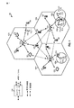
[0043]eノード110は、マクロセル、ピコセル、フェムトセル、および/または他のタイプのセルに対する通信カバレージを与え得る。マクロセルは、比較的大きい地理的エリア(たとえば、半径数キロメートル)をカバーし得、サービスに加入している(with service subscription)UE120による無制限のアクセスを可能にし得る。ピコセルは、比較的小さい地理的エリアをカバーし得、サービスに加入しているUE120による無制限のアクセスを可能にし得る。フェムトセルは、比較的小さい地理的エリア(たとえば、自宅)をカバーし得、フェムトセルとの関連付けを有するUE120(たとえば、UE120は限定加入者グループ(CSG:Closed Subscriber Group)に加入し得、自宅内のユーザのためのUE120など)による制限付きアクセスを可能にし得る。マクロセルのためのeノードB110はマクロeノードBと呼ばれることがある。ピコセルのためのeノードB110はピコeノードBと呼ばれることがある。フェムトセルのためのeノードB110はフェムトeノードBまたはホームeノードBと呼ばれることがある。図1に示された例では、eノードB110a、110bおよび110cは、それぞれマクロセル102a、102bおよび102cのためのマクロeノードBであり得る。eノードB110xは、ピコセル102xのためのピコeノードBであり得る。eノードB110yおよび110zは、それぞれフェムトセル102yおよび102zのためのフェムトeノードBであり得る。eノードB110は、1つまたは複数(たとえば、3つ)のセルに対する通信カバレージを与え得る。
[0043] The e-node 110 may provide communication coverage for macro cells, pico cells, femto cells, and / or other types of cells. A macro cell may cover a relatively large geographic area (eg, a few kilometers in radius) and may allow unrestricted access by
[0044]電気通信ネットワークシステム100は、リレーeノードB、リレーなどと呼ばれることもある、1つまたは複数のリレー局110rおよび120rを含み得る。リレー局110rは、上流局(an upstream station)(たとえば、eノードB110またはUE120)からデータおよび/または他の情報の送信を受信し、データおよび/または他の情報の受信された送信を下流局(a downstream station)(たとえば、UE120またはeノードB110)に送る局であり得る。リレー局120rは、他のUE(図示せず)に対する送信を中継するUEであり得る。図1に示された例では、リレー局110rは、eノードB110aとUE120rとの間の通信を可能にするために、eノードB110aおよびUE120rと通信し得る。
[0044] The
[0045]電気通信ネットワークシステム100は、異なるタイプのeノードB110、たとえば、マクロeノードB110a〜c、ピコeノードB110x、フェムトeノードB110y〜z、リレー110rなどを含む異機種ネットワークであり得る。これらの異なるタイプのeノードB110は、電気通信ネットワークシステム100において異なる送信電力レベル、異なるカバレージエリア、および干渉に対する異なる影響を有し得る。たとえば、マクロeノードB110a〜cは、高い送信電力レベル(たとえば、20ワット)を有し得るが、ピコeノードB110x、フェムトeノードB110y〜zおよびリレー110rは、より低い送信電力レベル(たとえば、1ワット)を有し得る。
[0045] The
[0046]以下でより詳細に説明するように、本開示の態様は、異なる送信電力レベルをもつ異なるタイプの基地局による、たとえば、ダウンリンクサービスを提供するマクロeノードB、およびアップリンクサービスを提供する、フェムトeノードB110y〜zおよび/またはリレー110r/120rなどの低電力ノードによる、UE120などのデバイスの、分離されたアップリンクとダウンリンクとのサービスを可能にする。
[0046] As described in more detail below, aspects of the present disclosure may include, for example, macro eNodeBs that provide downlink services and uplink services by different types of base stations with different transmit power levels. It provides a separate uplink and downlink service for devices such as
[0047]電気通信ネットワークシステム100は同期動作または非同期動作をサポートし得る。同期動作の場合、複数のeノードB110は同様のフレームタイミングを有し得、異なる複数のeノードB110からの送信は時間的に近似的に整合され得る。非同期動作の場合、複数のeノードB110は異なるフレームタイミングを有し得、異なる複数のeノードB110からの送信は時間的に整合されないことがある。本明細書で説明する技法は、同期動作と非同期動作の両方のために使用され得る。
[0047] The
[0048]ネットワークコントローラ130は、eノードB110のセットに結合され、これらのeノードB110のための協調および制御を行い得る。ネットワークコントローラ130は、バックホール(図示せず)を介してeノードB110と通信し得る。複数のeノードB110はまた、たとえば、ワイヤレス(オーバーザエア「OTA:over the air」)またはワイヤーライン・バックホール(たとえば、図示されていないX2インターフェース)を介して直接または間接的に、互いに通信し得る。
[0048]
[0049]UE120(たとえば、120x、120yなど)は電気通信ネットワークシステム100全体にわたって分散され得、各UE120は固定式または移動性であり得る。UE120は、マクロeノードB110a〜c、ピコeノードB110x、フェムトeノードB110y〜z、リレー110rなどと通信することが可能であり得る。たとえば、図1において、両矢印付きの実線は、ダウンリンクおよび/またはアップリンク上でUE120をサービスするように指定されたeノードB110であるサービングeノードB110と、そのUE120との間の所望の送信を示し得る。両矢印付きの破線は、UE120とeノードB110との間の干渉送信を示し得る。
[0049] UEs 120 (eg, 120x, 120y, etc.) may be distributed throughout the
[0050]LTEは、ダウンリンク上で直交周波数分割多重(OFDM)を利用し、アップリンク上でシングルキャリア周波数分割多重(SC−FDM)を利用し得る。OFDMおよびSC−FDMは、システム帯域幅を、一般にトーン、ビンなどとも呼ばれる複数(K)個の直交サブキャリアに区分し得る。各サブキャリアはデータで変調され得る。概して、変調シンボルは、OFDMでは周波数領域中で、SC−FDMでは時間領域中で送られ得る。隣接するサブキャリア間の間隔は固定であり得、サブキャリアの総数(K)はシステム帯域幅に依存し得る。たとえば、サブキャリアの間隔は15kHzであり得、(「リソースブロック」と呼ばれる)最小リソース割振りは12個のサブキャリア(または180kHz)であり得る。したがって、公称(nominal)高速フーリエ変換(FFT)サイズは、1.25、2.5、5、10または20メガヘルツ(MHz)のシステム帯域幅に対してそれぞれ128、256、512、1024または2048に等しくなり得る。システム帯域幅はサブバンドに区分され得る。たとえば、サブバンドは1.08MHz(すなわち、6つのリソースブロック)をカバーし得、1.25、2.5、5、10または20MHzのシステム帯域幅に対してそれぞれ1、2、4、8または16個のサブバンドがあり得る。 [0050] LTE may utilize orthogonal frequency division multiplexing (OFDM) on the downlink and single carrier frequency division multiplexing (SC-FDM) on the uplink. OFDM and SC-FDM may partition the system bandwidth into multiple (K) orthogonal subcarriers, also commonly referred to as tones, bins, etc. Each subcarrier may be modulated with data. In general, modulation symbols may be sent in the frequency domain with OFDM and in the time domain with SC-FDM. The spacing between adjacent subcarriers may be fixed and the total number of subcarriers (K) may depend on the system bandwidth. For example, the subcarrier spacing may be 15 kHz and the minimum resource allocation (referred to as a “resource block”) may be 12 subcarriers (or 180 kHz). Thus, the nominal Fast Fourier Transform (FFT) size is 128, 256, 512, 1024 or 2048, respectively, for a system bandwidth of 1.25, 2.5, 5, 10 or 20 megahertz (MHz). Can be equal. The system bandwidth can be divided into subbands. For example, a subband may cover 1.08 MHz (ie 6 resource blocks), 1, 2, 4, 8, or 8 for a system bandwidth of 1.25, 2.5, 5, 10 or 20 MHz, respectively. There can be 16 subbands.
[0051]図2は、本開示の一態様による、ダウンリンクフレーム構造の一例を概念的に示すブロック図である。ダウンリンクの送信タイムラインは無線フレームの単位(units of radio frames)に区分され得る。各無線フレームは、所定の持続時間(たとえば、10ミリ秒(ms))を有し得、0〜9のインデックスをもつ10個のサブフレームに区分され得る。各サブフレームは2つのスロットを含み得る。したがって、各無線フレームは、0〜19のインデックスをもつ20個のスロットを含み得る。各スロットは、L個のシンボル期間、たとえば、(図2に示すように)ノーマルサイクリックプレフィックスの場合は7つのシンボル期間、または拡張サイクリックプレフィックスの場合(図示せず)は14個のシンボル期間を含み得る。各サブフレーム中の2L個のシンボル期間には0〜2L−1のインデックスが割り当てられ得る。利用可能な時間周波数リソースはリソースブロックに区分され得る。各リソースブロックは、1つのスロット中にN個のサブキャリア(たとえば、12個のサブキャリア)をカバーし得る。 [0051] FIG. 2 is a block diagram conceptually illustrating an example of a downlink frame structure according to an aspect of the present disclosure. The downlink transmission timeline can be divided into units of radio frames. Each radio frame may have a predetermined duration (eg, 10 milliseconds (ms)) and may be partitioned into 10 subframes with an index of 0-9. Each subframe may include two slots. Thus, each radio frame may include 20 slots with indexes 0-19. Each slot is L symbol periods, eg, 7 symbol periods for a normal cyclic prefix (as shown in FIG. 2), or 14 symbol periods for an extended cyclic prefix (not shown). Can be included. An index of 0-2L-1 may be assigned to 2L symbol periods in each subframe. Available time frequency resources may be partitioned into resource blocks. Each resource block may cover N subcarriers (eg, 12 subcarriers) in one slot.
[0052]たとえばLTEでは、eノードBは、eノードBのカバレージエリア中の各セルについて1次同期信号(PSS:primary synchronization signal)と2次同期信号(SSS:secondary synchronization signal)とを送り得る。1次同期信号(PSS)および2次同期信号(SSS)は、図2に示すように、それぞれ、ノーマルサイクリックプレフィックスをもつ各無線フレームのサブフレーム0および5の各々中のシンボル期間6および5中で送られ得る。同期信号は、セル検出および獲得のためにUEによって使用され得る。eノードBは、サブフレーム0のスロット1のシンボル期間0〜3中の物理ブロードキャストチャネル(PBCH:Physical Broadcast Channel)中でシステム情報を送り得る。
[0052] For example, in LTE, an eNodeB may send a primary synchronization signal (PSS) and a secondary synchronization signal (SSS) for each cell in the coverage area of the eNodeB. . As shown in FIG. 2, the primary synchronization signal (PSS) and the secondary synchronization signal (SSS) are respectively
[0053]eノードBは、図2の第1のシンボル期間全体において示されているが、各サブフレームの第1のシンボル期間の一部のみの中の物理制御フォーマットインジケータチャネル(PCFICH:Physical Control Format Indicator Channel)中で情報を送り得る。PCFICHは、制御チャネルのために使用されるいくつか(M個)のシンボル期間を搬送し得、ここで、Mは、1、2または3に等しくなり得、サブフレームごとに変化し得る。Mはまた、たとえば、リソースブロックが10個未満である、小さいシステム帯域幅では4に等しくなり得る。図2に示された例では、M=3である。eノードBは、各サブフレームの最初のM個(図2ではM=3)のシンボル期間中の物理HARQインジケータチャネル(PHICH:Physical HARQ Indicator Channel)と物理ダウンリンク制御チャネル(PDCCH:Physical Downlink Control Channel)との中で情報を送り得る。PHICHは、ハイブリッド自動再送信(HARQ)をサポートするための情報を搬送し得る。PDCCHは、UEのためのアップリンクおよびダウンリンクリソース割振りに関する情報と、アップリンクチャネルのための電力制御情報とを搬送し得る。図2の第1のシンボル期間の中には示されていないが、PDCCHおよびPHICHは第1のシンボル期間の中にも含まれることを理解されよう。同様に、PHICHおよびPDCCHはまた、図2にはそのようには示されていないが、第2のシンボル期間と第3のシンボル期間の両方の中にある。eノードBは、各サブフレームの残りのシンボル期間中の物理ダウンリンク共有チャネル(PDSCH:Physical Downlink Shared Channel)中で情報を送り得る。PDSCHは、ダウンリンク上でのデータ送信がスケジュールされたUEのためのデータを搬送し得る。LTEにおける様々な信号およびチャネルは、公開されている「Evolved Universal Terrestrial Radio Access (E-UTRA); Physical Channels and Modulation」と題する3GPP TS 36.211に記載されている。 [0053] Although eNode B is shown in the entire first symbol period of FIG. 2, the physical control format indicator channel (PCFICH) in only a portion of the first symbol period of each subframe. Information can be sent in the Format Indicator Channel). PCFICH may carry several (M) symbol periods used for the control channel, where M may be equal to 1, 2 or 3, and may vary from subframe to subframe. M can also be equal to 4 for small system bandwidths, eg, with less than 10 resource blocks. In the example shown in FIG. 2, M = 3. The eNodeB performs physical HARQ indicator channel (PHICH) and physical downlink control channel (PDCCH) during the first M (M = 3 in FIG. 2) symbol periods of each subframe. Information can be sent in (Channel). The PHICH may carry information to support hybrid automatic retransmission (HARQ). The PDCCH may carry information regarding uplink and downlink resource allocation for the UE and power control information for the uplink channel. Although not shown in the first symbol period of FIG. 2, it will be understood that PDCCH and PHICH are also included in the first symbol period. Similarly, PHICH and PDCCH are also in both the second and third symbol periods, although not shown as such in FIG. The eNodeB may send information in a physical downlink shared channel (PDSCH) during the remaining symbol periods of each subframe. The PDSCH may carry data for UEs scheduled for data transmission on the downlink. Various signals and channels in LTE are described in the published 3GPP TS 36.211 entitled “Evolved Universal Terrestrial Radio Access (E-UTRA); Physical Channels and Modulation”.
[0054]eノードBは、eノードBによって使用されるシステム帯域幅の中心1.08MHzの周りにPSS、SSSおよびPBCHを送り得る。eノードBは、これらのチャネルが送られる各シンボル期間中のシステム帯域幅全体にわたってPCFICHおよびPHICHを送り得る。eノードBは、システム帯域幅のいくつかの部分においてUEのグループにPDCCHを送り得る。eノードBは、システム帯域幅の特定の部分において特定のUEにPDSCHを送り得る。eノードBは、カバレージエリア中のすべてのUEにブロードキャスト方式でPSS、SSS、PBCH、PCFICHおよびPHICHを送り得る。eノードBは、カバレージエリア中の特定のUEにユニキャスト方式でPDCCHを送り得る。eノードBはまた、カバレージエリア中の特定のUEにユニキャスト方式でPDSCHを送り得る。 [0054] The eNodeB may send PSS, SSS and PBCH around the center 1.08 MHz of the system bandwidth used by the eNodeB. The eNodeB may send PCFICH and PHICH across the entire system bandwidth during each symbol period during which these channels are sent. An eNodeB may send a PDCCH to a group of UEs in some part of the system bandwidth. An eNodeB may send a PDSCH to a specific UE in a specific part of the system bandwidth. The eNodeB may send PSS, SSS, PBCH, PCFICH and PHICH to all UEs in the coverage area in a broadcast manner. An eNodeB may send a PDCCH in a unicast manner to a specific UE in the coverage area. The eNodeB may also send PDSCH in a unicast manner to specific UEs in the coverage area.
[0055]各シンボル期間においていくつかのリソース要素が利用可能であり得る。各リソース要素は、1つのシンボル期間中に1つのサブキャリアをカバーし得、実数値または複素数値であり得る1つの変調シンボルを送るために使用され得る。各シンボル期間中に基準信号のために使用されないリソース要素は、リソース要素グループ(REG:resource element group)にアレンジされ(arranged into)得る。各REGは、1つのシンボル期間中に4つのリソース要素を含み得る。PCFICHは、シンボル期間0において、周波数にわたってほぼ等しく離間され得る、4つのREGを占有し得る。PHICHは、1つまたは複数の構成可能なシンボル期間において、周波数にわたって拡散され得る、3つのREGを占有し得る。たとえば、PHICHのための3つのREGは、すべてシンボル期間0に属し得るか、またはシンボル期間0、1および2に拡散され得る。PDCCHは、最初のM個のシンボル期間において、利用可能なREGから選択され得る、9、18、32または64個のREGを占有し得る。REGのいくつかの組合せのみがPDCCHに対して許可され得る。
[0055] Several resource elements may be available in each symbol period. Each resource element may cover one subcarrier during one symbol period and may be used to send one modulation symbol that may be real-valued or complex-valued. Resource elements that are not used for the reference signal during each symbol period may be arranged into a resource element group (REG). Each REG may include four resource elements in one symbol period. The PCFICH may occupy four REGs that may be approximately equally spaced across the frequency in symbol period 0. The PHICH may occupy three REGs that may be spread over frequency in one or more configurable symbol periods. For example, the three REGs for PHICH can all belong to symbol period 0 or can be spread into
[0056]UEは、PHICHおよびPCFICHのために使用される特定のREGを知り得る。UEは、PDCCHについてREGの様々な組合せを探索し得る。探索すべき組合せの数は、一般に、PDCCHに対して許可される組合せの数よりも少ない。eノードBは、UEが探索することになる組合せのいずれかにおいてUEにPDCCHを送り得る。 [0056] The UE may know the specific REG used for PHICH and PCFICH. The UE may search for various combinations of REGs for PDCCH. The number of combinations to search is generally less than the number of combinations allowed for the PDCCH. The eNodeB may send a PDCCH to the UE in any of the combinations that the UE will search.
[0057]UEは、複数のeノードB(または他のタイプの基地局)のカバレージエリア内にあり得る。そのUEをサービスするために、これらのeノードBのうちの1つが選択され得る。サービングeノードBは、受信電力、経路損失、信号対雑音比(SNR)など、様々な基準に基づいて選択され得る。 [0057] A UE may be within the coverage area of multiple eNodeBs (or other types of base stations). One of these eNodeBs may be selected to serve that UE. The serving eNodeB may be selected based on various criteria such as received power, path loss, signal to noise ratio (SNR).
[0058]さらに、本開示の態様は、複数の基地局がそのような基準に基づいて選択されることを可能にし、デバイスの分離されたアップリンクおよびダウンリンクサービスを可能にする。たとえば、UEにダウンリンクサービスを提供するためにダウンリンク基準信号の受信電力に基づいてマクロeノードBが選択され得るが、同じUEにアップリンクサービスを提供するために、(たとえば、低電力ノードによって測定され、報告される、UEからのアップリンク送信に基づいて決定された)経路損失に基づいて低電力ノードが選択され得る。 [0058] Furthermore, aspects of this disclosure allow multiple base stations to be selected based on such criteria, allowing for separate uplink and downlink services for the device. For example, a macro eNodeB may be selected based on received power of a downlink reference signal to provide a downlink service to the UE, but to provide an uplink service to the same UE (eg, a low power node A low power node may be selected based on path loss (determined based on uplink transmission from the UE) measured and reported by.
[0059]図3は、本開示の一態様に従って構成された例示的なeノードB310と例示的なUE320とを概念的に示すブロック図である。たとえば、UE315は、図1に示されたUE120の一例であり得、本開示の態様に従って動作することが可能であり得る。
[0059] FIG. 3 is a block diagram conceptually illustrating an
[0060]基地局310はアンテナ3341〜tを装備し得、UE320はアンテナ3521〜rを装備し得、ここにおいて、tおよびrは1よりも大きいかまたはそれに等しい整数である。基地局310において、基地局送信プロセッサ314は、基地局データソース312からデータを受信し、基地局コントローラ/プロセッサ340から制御情報を受信し得る。制御情報は、PBCH、PCFICH、PHICH、PDCCHなどの上で搬送され得る。データは、PDSCHなどの上で搬送され得る。基地局送信プロセッサ314は、データと制御情報とを処理(たとえば、符号化およびシンボルマッピング)して、それぞれデータシンボルと制御シンボルとを取得し得る。基地局送信プロセッサ314はまた、たとえば、PSS、SSS、およびセル固有基準信号(RS:reference signal)のための、基準シンボルを生成し得る。基地局送信(TX)多入力多出力(MIMO)プロセッサ330は、適用可能な場合、データシンボル、制御シンボル、および/または基準シンボルに対して空間処理(たとえば、プリコーディング)を実行し得、出力シンボルストリームを基地局変調器/復調器(MOD/DEMOD)3321〜tに与え得る。各基地局変調器/復調器332は、(たとえば、OFDMなどのために)それぞれの出力シンボルストリームを処理して、出力サンプルストリームを取得し得る。各基地局変調器/復調器332はさらに、出力サンプルストリームを処理(たとえば、アナログへの変換、増幅、フィルタ処理、およびアップコンバート)して、ダウンリンク信号を取得し得る。変調器/復調器3321〜tからのダウンリンク信号は、それぞれアンテナ3341〜tを介して送信され得る。
[0060] The resulting
[0061]UE315において、UEアンテナ3521〜rは、基地局310からダウンリンク信号を受信し得、受信信号をそれぞれUE変調器/復調器(MOD/DEMOD)3541〜rに与え得る。各UE変調器/復調器354は、それぞれの受信信号を調整(たとえば、フィルタ処理、増幅、ダウンコンバート、およびデジタル化)して、入力サンプルを取得し得る。各UE変調器/復調器354は、(たとえば、OFDMなどのために)入力サンプルをさらに処理して、受信シンボルを取得し得る。UE MIMO検出器356は、すべてのUE変調器/復調器3541〜rから受信シンボルを取得し、適用可能な場合は受信シンボルに対してMIMO検出を実行し、検出シンボルを与え得る。UE受信プロセッサ358は、検出シンボルを処理(たとえば、復調、デインターリーブ、および復号)し、UE320の復号されたデータをUEデータシンク360に与え、復号された制御情報をUEコントローラ/プロセッサ380に与え得る。
[0061] At UE 315,
[0062]アップリンク上では、UE315において、UE送信プロセッサ364は、UEデータソース362から(たとえば、PUSCHのための)データを受信し、処理し得、UEコントローラ/プロセッサ380から(たとえば、PUCCHのための)制御情報を受信し、処理し得る。UE送信プロセッサ364はまた、基準信号のための基準シンボルを生成し得る。UE送信プロセッサ364からのシンボルは、適用可能な場合はUE TX MIMOプロセッサ366によってプリコードされ、さらに(たとえば、SC−FDMなどのために)UE変調器/復調器3541〜rによって処理され、基地局310に送信され得る。基地局310において、UE315からのアップリンク信号は、基地局アンテナ334によって受信され、基地局変調器/復調器332によって処理され、適用可能な場合は基地局MIMO検出器336によって検出され、さらに基地局受信プロセッサ338によって処理されて、UE315によって送られた復号されたデータと制御情報とが取得され得る。基地局受信プロセッサ338は、復号されたデータを基地局データシンク346に与え、復号された制御情報を基地局コントローラ/プロセッサ340に与え得る。
[0062] On the uplink, at UE 315, UE transmit
[0063]基地局コントローラ/プロセッサ340およびUEコントローラ/プロセッサ380は、それぞれ基地局310およびUE315における動作を指示し得る。基地局310における基地局コントローラ/プロセッサ340および/または他のプロセッサおよびモジュールは、たとえば、本明細書で説明する技法のための様々なプロセスを実行するか、またはその実行を指示し得る。UE315におけるUEコントローラ/プロセッサ380および/または他のプロセッサおよびモジュールはまた、たとえば、図4および図5に示された機能ブロック、および/または本明細書で説明する技法のための他のプロセスを実行するか、またはその実行を指示し得る。基地局メモリ342およびUEメモリ382は、それぞれ基地局310およびUE315のためのデータおよびプログラムコードを記憶し得る。スケジューラ344は、ダウンリンクおよび/またはアップリンク上でのデータ送信のためにUE315をスケジューリングし得る。
[0063] Base station controller /
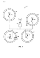
[0064]図4は、本開示の一態様による、異機種ワイヤレス通信システム400の一例を概念的に示すブロック図である。図示の例では、マクロeノードB402は、たとえば、インターフェース(たとえば、光ファイバーをもつX2インターフェース)を介して、低電力ノード(LPN)404、406、408、および410に結合され得る。上述したように、LPN404〜410は、マクロeノードB402に比べてより低い送信電力を有し得、たとえば、ピコ基地局、リレー、またはリモートラジオヘッド(RRH)であり得る。したがって、マクロeノードB402は、LPN404〜410のカバレージエリアを包含する(または少なくともそれと重複する)カバレージエリアを有し得る。LPN404〜410およびマクロeノードB402は、たとえば、図3に示された基地局310について示された様々な構成要素を使用して実装され得る。同様に、MTCデバイス420および422は、たとえば、図3に示されたUE320について示された様々な構成要素を使用して実装され得る。
[0064] FIG. 4 is a block diagram conceptually illustrating an example of a heterogeneous
[0065]いくつかの態様によれば、LPN404〜410は、マクロeノード402と同じセル識別子(ID)で構成されるか、または異なるセルIDで構成され得る。LPN404〜410が同じセルIDで構成された場合、マクロeノードB402およびLPN404〜410は、マクロeノードB402によって制御される本質的に1つのセルとして動作し得る。一方、LPN404〜410およびマクロeノードB402が異なるセルIDで構成された場合、マクロeノードB402およびLPN404〜410は、UEには異なるセルのように見え得るが、すべての制御およびスケジューリングは、依然としてマクロeノードB402にとどまり得る。
[0065] According to some aspects, the LPNs 404-410 may be configured with the same cell identifier (ID) as the
ロングタームエボリューションのための例示的な分離されたダウンリンクおよびアップリンク動作
[0066]UL通信とDL通信との分離(UL and DL communications decoupling)が起こり得る、異機種ワイヤレス通信システム400内の様々なロケーションがある。たとえば、各LPN(404、406、408、および410)は、ULサービスゾーンと呼ばれる対応する領域(434、436、438、440)を有し得、その中において、MTCデバイス(420、422)は、マクロeノードB402からDL通信を受信し、LPN404〜410にUL通信を送信し得る。たとえば、ULサービスゾーン438内で、MTCデバイス420は、マクロeノードB402からDLサービスを受信し、LPN408からULサービスを受信し得る。同様に、ULサービスゾーン434内で、MTCデバイス422は、マクロeノードB402からDLサービスを受信し、LPN404からULサービスを受信し得る。
Exemplary separated downlink and uplink operation for long term evolution
[0066] There are various locations within the heterogeneous
[0067]しかしながら、場合によっては、MTCデバイスが(ULサービスゾーンの内側境界よりも)LPNに近づいた場合、MTCデバイスは、マクロeノードB402ではなくLPNからDLサービスをも受信し得る。言い換えれば、このエリア内で、MTCは、LPNからULサービスとDLサービスの両方を受信し得る。
[0067] However, in some cases, if the MTC device approaches the LPN (rather than the inner boundary of the UL service zone), the MTC device may also receive DL service from the LPN rather than the
[0068]MTCデバイスは、最良の信号強度をもつセルからのDL送信を探索することによってセル獲得(cell acquisition)を実行し得る。最良の信号強度をもつ信号から、MTCデバイスは、物理セル識別子(PCI:physical cell identifier)を取得し、時間トラッキングループ(TTL:time tracking loop)と周波数トラッキングループ(FTL:frequency tracking loop)とを維持し得る。本明細書で説明するように、MTCデバイスは、事実上、DLサービスとULサービスとのためにセル獲得を別々に実行し得る。この目的を達成するために、MTCデバイスは、(たとえば、上述したように信号強度に基づいて識別されたLPNセルで)別個のランダムアクセスチャネル(RACH)プロシージャを実行し得る。 [0068] The MTC device may perform cell acquisition by searching for DL transmissions from the cell with the best signal strength. From the signal having the best signal strength, the MTC device obtains a physical cell identifier (PCI), and performs a time tracking loop (TTL) and a frequency tracking loop (FTL). Can be maintained. As described herein, the MTC device may effectively perform cell acquisition separately for DL and UL services. To achieve this goal, the MTC device may perform a separate random access channel (RACH) procedure (eg, with an LPN cell identified based on signal strength as described above).
[0069]場合によっては、MTCデバイスによるRACHプロシージャのための構成が、MTCデバイスをターゲットにするシステム情報ブロック(SIB:system information block)中で搬送され、この情報はLPNと共有され、MTCデバイスがRACH検出を実行することを可能にし得る。場合によっては、このRACH構成はマクロセルIDにリンクされ得、RACHシーケンス、タイミング、および電力情報を含み得る。場合によっては、RACH構成は、(図11に示されたMSG2 RACH応答および/またはMSG3 RRC接続要求メッセージなどの)RACHメッセージのタイミング、ならびに変調およびコーディング方式(MCS:modulation and coding scheme)およびリソースブロック(RB:resource block)割当て情報をも含み得る。場合によっては、そのような情報はマクロeノードBカバレージエリア内の複数のLPNと共有され、それらのLPNがMTCデバイスのためにRACH検出を実行することを可能にし得る。一例では、マクロeノードBカバレージエリア内の複数のLPNが、MTCデバイスからのRACHメッセージを検出し得る。以下で説明するように、複数のLPNは、(たとえば、受信信号強度または信号対雑音比を示す)MTC RACH検出についての測定値報告を送り、それによって、マクロeノードBが、MTCデバイスためのULサービスを提供するためにそれらの複数のLPNのうちの1つ(または複数)を選択することを可能にし得る(たとえば、MTC RACH検出について最も強い報告された信号強度をもつLPN)。 [0069] In some cases, the configuration for the RACH procedure by the MTC device is carried in a system information block (SIB) targeting the MTC device, this information is shared with the LPN, and the MTC device It may be possible to perform RACH detection. In some cases, this RACH configuration may be linked to a macro cell ID and may include RACH sequence, timing, and power information. In some cases, the RACH configuration may include the timing of RACH messages (such as the MSG2 RACH response and / or MSG3 RRC connection request message shown in FIG. 11), and modulation and coding scheme (MCS) and resource blocks. (RB: resource block) allocation information may also be included. In some cases, such information may be shared with multiple LPNs in the macro eNodeB coverage area and allow those LPNs to perform RACH detection for MTC devices. In one example, multiple LPNs in a macro eNodeB coverage area may detect a RACH message from an MTC device. As described below, multiple LPNs send measurement reports for MTC RACH detection (eg, indicating received signal strength or signal-to-noise ratio) so that the macro eNodeB can It may be possible to select one (or more) of those multiple LPNs to provide UL service (eg, LPN with the strongest reported signal strength for MTC RACH detection).
[0070]図5に、図4のMTCデバイス422とマクロeノードB402とLPN404とを伴うRACHプロシージャのための送信の交換のための例示的なコールフロー図500を示す。単一のLPN404が示されているが、(高密度展開における)いくつかのLPNが、本明細書で説明する動作と同様の動作を独立して実行している(たとえば、各々がRACH検出を報告している)ことがあることを理解されたい。
[0070] FIG. 5 shows an exemplary call flow diagram 500 for the exchange of transmissions for a RACH procedure involving the
[0071]ステップ0a)に示されているように、マクロeノードB402が、(たとえば、特別なMTC SIB送信を介して)RACH構成を用いてMTCデバイス422を構成し得る。ステップ0において、MTCデバイス422は、たとえば、マクロPSS/SSS信号および/またはそのMTC SIB送信に基づいて、セル獲得を実行する。たとえば、MTCデバイス422は、マクロeノードB402によってブロードキャストされたPSS/SSS信号および/またはMTC SIB送信を受信し得、MTCデバイス422はセル獲得を実行し得る。図示のように、ステップ0b)において、マクロeノードB402はまた、(たとえば、ファイバー、X2またはOTAを介して)LPN404にMTC RACH構成をシグナリングし得る。代替として、LPN404は、リッスン(たとえば、MTC SIB送信を検出すること)によってこの情報を獲得し得る。
[0071] As shown in step 0a), the
[0072]いずれの場合も、MTC RACH情報(たとえば、一意のMTC RACHプリアンブルおよびMTC RACHオケージョンのタイミング(timing of MTC RACH occasion))を取得すると、LPN404は、MTCデバイス422からの(たとえば、マクロeノードB402に関連する)MTC RACHプロシージャを検出し、対応する電力測定値および/または所望のUL構成をマクロeノードB402に報告することが可能であり得る。このようにして、マクロeノードB402は、MTCデバイス422にUL(および/またはDL)サービスを与えるために最良のLPNのうちの1つまたは複数を選択し得る。
[0072] In either case, upon obtaining MTC RACH information (eg, unique MTC RACH preamble and timing of MTC RACH occasion),
[0073]ステップ1において、MTCデバイス422は、(たとえば、マクロeノードB402によって与えられたマクロeノードB IDを有するMTC RACH情報を使用して)RACHプロシージャを実行する。一実施形態による、RACHプロシージャのさらなる詳細については、図11を参照しながら以下で説明する。MTC RACH情報を取得すると、1つまたは複数のLPN404は、1aにおいて、MTC RACHを検出し、検出された電力レベルをマクロeノードB402に報告することが可能になる。図示のように、1つまたは複数のLPN404は、MTCデバイス422をサービスするための所望のUL構成をも送り得る。
[0073] In
[0074]図示の例では、ステップ1b)において、マクロeノードB402は、報告されたRACH検出に基づいて、MTCデバイス422にULサービスを与えるための1つまたは複数のLPN404を選択する。いくつかの実施形態では、LPNは、報告中に示されたRACH検出の信号強度を示し得る。いくつかの実施形態では、LPN404は、しきい値強度(たとえば、受信強度またはSNR)を上回るRACH送信が検出されたときのみ報告し得、したがって、報告自体は、少なくとも(マクロeノードB402によってLPN404にシグナリングされ得る)そのしきい値強度をもつRACH送信が検出されたことを示す。いずれの場合も、マクロeノードBは、それの選択を1つまたは複数のLPN404に通知し得る。マクロeノードB402はまた、たとえば、ULおよび/またはDL上でMTCデバイス422をサービスする際に使用するためのパラメータ(たとえば、ULおよび/またはDL構成)を示す情報を1つまたは複数のLPN404にシグナリングし得る。場合によっては、ジョイントUL受信(joint UL reception)が望まれる場合、マクロeノードB402は、MTCデバイス422をサービスするために、ジョイント処理構成(joint processing configuration)を複数のLPN404に通知し得る。同様に、ジョイントDL送信が望まれる場合、マクロeノードB402はまた、MTCデバイス422へのDLサービスのために複数のLPN404が選択されたことをそれらの複数のLPN404に通知し得る。
[0074] In the illustrated example, in step 1b), the
[0075]ステップ2において、マクロeノードB402は、MTCデバイス422のULおよびDL構成に関してMTCデバイス422にシグナリングし、それによって、MTCデバイス422が、(たとえば、LPN404を介して)マクロeノードB402からDL送信を受信し、UL送信を実行することを可能にする。この情報は、たとえば、MSG2(ランダムアクセス応答)中で与えられ得る。ULおよびDL構成情報は、DLおよびUL送信の時間、UL送信の電力、DLおよびUL送信のための物理セル識別子(PCI)または仮想セル識別子(VCI:virtual cell identifier)、(たとえば、競合解消(contention resolution)のための)物理ダウンリンク共有チャネル(PDSCH)および/または物理アップリンク共有チャネル(PUSCH:physical uplink shared channel)割当て、データ送信のための永続的割当て(たとえば、RBおよび/またはMCS)を含み得る。
[0075] In
[0076]アップリンク通信とダウンリンク通信とを正常に分離すると、ステップ3において、MTCデバイス422は、(ステップ2において受信された構成情報、たとえば、LPN404の物理セル識別子(PCI)または仮想セル識別子(VCI)を使用して)UL送信をLPN404に送り、場合によっては、ステップ4において、マクロeノードB402からDL送信を受信し得る。言い換えれば、DL送信をサービスするためにマクロeノードB402によってLPN404が選択されたとき、LPN404は、MTCデバイス422のためにDL送信をもサービスし得る。
[0076] Upon successful separation of uplink communication and downlink communication, in
[0077]場合によっては、たとえば、(マクロeノードBが依然としてDLサービスを与えるので)マクロeノードBを介した(LPNへの)UL送信のための制御情報をMTCデバイスに与えるために、ULサービスとDLサービスとの分離を考慮するためのいくつかのルーチンプロシージャが調整され得る。たとえば、時間トラッキングに関して、アップリンク上でLPNに送信するときにMTCデバイスによって適用されるべきタイミングアドバンス(TA:timing advance)コマンドも、マクロeノードBから送られ得る。周波数トラッキングでは、LPNはUL周波数補償のためのFTLを維持し得るか、または、マクロeノードBは、UL送信のために適用すべき周波数オフセットをMTCにシグナリングし得る。そのようなタイミングアドバンスおよび/または周波数オフセット調整は、たとえば、図5のステップ3においてUL送信を送るときにMTCデバイス422によって適用され得る。場合によっては、たとえば、LPNとマクロeノードBとが同期されている場合(または周波数オフセットが小さく、LPNにおけるFTLによって処理され得る場合)、そのようなトラッキングは不要であり得る。電力制御に関して、ULデータのための初期送信電力設定はLPNによって決定され得るが、この設定は、マクロeノードBからMTCデバイスに送信され得る。後続の遅い電力制御調整も、(たとえば、LPNのために)マクロeノードBからMTCにシグナリングされ得る。
[0077] In some cases, for example, to provide the MTC device with control information for UL transmission (to the LPN) via the macro eNodeB (since the macro eNodeB still provides DL service) Several routine procedures for considering the separation of services and DL services can be coordinated. For example, for time tracking, a timing advance (TA) command to be applied by the MTC device when transmitting to the LPN on the uplink may also be sent from the macro eNodeB. For frequency tracking, the LPN may maintain FTL for UL frequency compensation, or the macro eNodeB may signal the frequency offset to be applied for UL transmission to the MTC. Such timing advance and / or frequency offset adjustment may be applied by
[0078]MTC開始型DLトラフィック(MTC initiated DL traffic)に関して、トラフィックがダウンリンク上にある場合でも、MTCデバイスは、データをネットワークにプッシュさせるのではなくデータをプルするために、依然として最初にRACHプロシージャを開始し得る。この場合、上記で説明した技法は、UL動作とDL動作とを分離するために依然として使用され得る。ネットワーク開始型DLトラフィック(network initiated DL traffic)では、ネットワークはMTCをページングする必要があり得る。ページは、(たとえば、最も強いDLセルから)MTCデバイスによって周期的に監視されるページングエリア中で送られ得る。MTCのためのページング構成は、SIB中でシグナリングされるか、または各デバイスに対して構成され得る。いずれの場合も、MTCデバイスがページングを検出した場合、MTCデバイスはRACHプロシージャを開始し得、この場合も、上記で説明した技法は、UL動作とDL動作とを分離するために依然として使用され得る。 [0078] With respect to MTC initiated DL traffic, even if the traffic is on the downlink, the MTC device will still initially RACH to pull the data instead of pushing it to the network. The procedure can be started. In this case, the techniques described above can still be used to separate UL and DL operations. For network initiated DL traffic, the network may need to page the MTC. Pages may be sent in a paging area that is periodically monitored by the MTC device (eg, from the strongest DL cell). The paging configuration for MTC may be signaled in the SIB or configured for each device. In either case, if the MTC device detects paging, the MTC device may initiate a RACH procedure, and again the techniques described above may still be used to separate UL and DL operations. .
[0079]いくつかの態様によれば、マクロeノードBは、すべてのコアネットワーク側の通信を処理し得、それは、MTCデバイスの観点から、マクロeノードBセルがまだサービングセルと見なされ得るときから動作し得る。しかしながら、代替として、LPNは、一部または全部のコアネットワーク側の通信を処理し得る。 [0079] According to some aspects, the macro eNodeB may handle all core network side communications, from the point of view of the MTC device, when the macro eNodeB cell may still be considered as a serving cell. Can work from. Alternatively, however, the LPN may handle some or all of the core network side communications.
[0080]本技法について、本明細書ではLTEおよび3Gネットワーク(GSMおよび/またはUMTS)において通信することが可能なUEに関して説明したが、本明細書で提示する技法は、様々な異なるRATネットワークにおいて適用され得る。 [0080] Although this technique has been described herein with reference to UEs capable of communicating in LTE and 3G networks (GSM and / or UMTS), the techniques presented herein can be used in a variety of different RAT networks. Can be applied.
分離されたアップリンク(UL)およびダウンリンク(DL)通信を可能にするための低電力ノード(LPN)とマクロセルとの間の例示的なインターフェース
[0081]上述のように、大きい透過損失(penetration loss)を伴うエリア中にあり得るマシンタイプ通信(MTC)デバイス(たとえば、MTC420、422)に対する有効なカバレージを与える1つの方法は、セル分割を用いて最も近いノードへの経路損失を低減するために、マクロ基地局(BS)カバレージエリア(たとえば、マクロ402)内に低電力ノード(LPN)(たとえば、LPN404〜410)を展開することである。しかしながら、同じく上述したように、マクロBSからLPNへの大きい送信電力差(transmit power difference)により最良のDLが常に最良のULであるとは限らないので、アップリンク(UL)/ダウンリンク(DL)分離が望ましい。ユーザ機器(UE)、LPN、およびマクロBSのための例示的な分離された動作について上記で説明した。たとえば、低レイテンシ要件(low latency requirement)および低スペクトル効率要件(low latency requirement)など、MTCトラフィックの特定の特徴を活用することによって、分離されたUL/DL動作が可能になり得る。
Exemplary interface between a low power node (LPN) and a macro cell for enabling separated uplink (UL) and downlink (DL) communications
[0081] As noted above, one method of providing effective coverage for machine type communication (MTC) devices (eg,
[0082]本明細書では、制御プレーンシグナリングとULデータフォワーディングとを可能にするためにマクロセルとLPNとの間のインターフェースのための技法および装置を提供する。 [0082] This document provides techniques and apparatus for an interface between a macro cell and an LPN to allow control plane signaling and UL data forwarding.
[0083]図6に、本開示のいくつかの態様による、分離されたDL/UL動作のための例示的なアーキテクチャおよびコールフロー600を示す。図6に示されているように、MTCデバイス622へのすべてのDLシグナリングはマクロセル602からMTCデバイス622に送信され得る。MTCトラフィックの場合、ランダムアクセスチャネル(RACH)および自動再送要求(ARQ)タイミングが緩和され得る。MTCトラフィックの遅延トレランスを活用することによって、およびLPN604とマクロBS602との間の新しいメッセージ交換を利用することによって、分離されたDL/UL動作が可能になり得る。
[0083] FIG. 6 illustrates an example architecture and
[0084]いくつかの態様によれば、UE ULフォワーディングアクティブ化(UE UL forward activation)はLPN604によって開始され得る。図6に見られるように、1において、マクロセル602はシステム情報をMTCデバイス622に送り得る。2において、MTCデバイス622は、次いで、LPN604にMTC_RACHをシグナリングし得る。LPN604は、MTC_RACHを検出し、3において、RACH情報(たとえば、タイミングアドバンス(TA)、信号対雑音比(SNR)、および/または電力)をもつRACH検出メッセージを送ることによって、RACHが検出されたことをマクロセル602に通知し得る。4において、マクロセル602は、ULをサービスするためのLPN604を選択し得、選択結果は肯定的または否定的であり得る。5において、LPN604はULスケジューリングおよび構成(たとえば、リソースブロック(RB)、変調およびコーディング方式(MCS)、TA、電力制御など)をマクロセル602に通知し得、6において、マクロセル602は、次いで、DL/ULスケジューリングおよび構成をMTCデバイス622にシグナリングし得る。7aにおいて、MTCデバイス622はULデータをシグナリングし得、7bにおいて、LPN604は、そのULデータをインターセプトし、マクロセル602にフォワーディングし得る。7cにおいて、マクロセル602はDLデータをMTCデバイス622に送り得る。
[0084] According to some aspects, UE UL forward activation may be initiated by
[0085]いくつかの態様によれば、LPN支援RACH(LPN-assisted RACH)の場合、(4における)ULサービングのためのLPN選択を示すLPN604へのマクロセル602信号と、(5における)ULスケジューリングおよび構成をマクロセル602に通知するマクロセル602へのLPN604信号とは、マクロセル602がMTCデバイス622(たとえば、UE)からのRACHメッセージに基づいて動作する前に交換され得る。
[0085] According to some aspects, for LPN-assisted RACH (LPN-assisted RACH),
[0086]代替的に、マクロセル602は、MTCデバイス622から直接RACHを受信し、UL/DLスケジューリング構成を進める(言い換えれば、上記のプロシージャ中のステップ2〜5をスキップする)。複数の態様では、マクロセル602は、次いで、MTCデバイス622のためにLPN604を使用すべきかどうかを決定するために、LPN604からのRACH検出を使用し、次いで、ULシグナリング(たとえば、ステップ2)をサービスするためのLPN選択を進め得る。
[0086] Alternatively, the
[0087] 複数の態様では、MTCデバイス622からLPN604へのUE ULデータ転送は、7aにおいて、媒体アクセス制御(MAC)プロトコルデータユニット(MPDU)からなり得る。複数の態様では、LPN604はまた、必要な場合、ULスケジューリング情報をマクロセル602にフォワーディングし得る。
[0087] In aspects, the UE UL data transfer from the
[0088]図7に、本開示のいくつかの態様による、(たとえば、MTCデバイス622と同様の)UE722、(たとえば、マクロセル602と同様の)eNB702、および(たとえば、LPN604と同様の)LPN704についての例示的なユーザプレーンプロトコルスタック700を示す。図7に示されているように、単一の無線リンク制御(RLC)703はマクロセル702に位置し得、単一のRLC701はUE722に位置し得る。上述のように、LPN704は、X4−APインターフェース705を介して、LPN704とeNB702との間のトンネリングを介してUE722からマクロセル702へのULデータをフォワーディングし得る。X4インターフェースは、X2と同じプロトコルスタックを有し得る新しいインターフェースであり得るか、またはMACレイヤおよび物理(PHY)レイヤにおけるX2インターフェースの拡張であり得る。
[0088] FIG. 7 illustrates a UE 722 (e.g., similar to MTC device 622), an eNB 702 (e.g., similar to macro cell 602), and an LPN 704 (e.g., similar to LPN 604) in accordance with certain aspects of the present disclosure. FIG. 6 illustrates an exemplary user
[0089]図8に、本開示のいくつかの態様による、LPN802とeNB802(たとえば、マクロセル)との間のX4インターフェースセットアッププロシージャ800のための例示的なコールフローを示す。図8に示されているように、1において、LPN904はX4セットアップ要求メッセージをeNB802にシグナリングし得る。2において、eNB802は、次いで、X4セットアップ応答メッセージをLPN804にシグナリングし得る。図8に示された例はLPN開始型X4セットアッププロシージャ(LPN-initiated X4 Setup procedure)についてのものであるが、複数の態様では、そのプロシージャは、代わりにeNB開始型(eNB initiated)であり得る。
[0089] FIG. 8 illustrates an example call flow for an X4 interface setup procedure 800 between an
[0090]いくつかの態様によれば、eNB802は、サービスされるセル情報IDまたはPRACH構成(たとえば、シーケンス、時間/周波数ロケーションなど)を削除、追加、または変更するために、サービスされるセルのリストを含み得るeNB構成更新メッセージ(a eNB Configuration Update message)をLPN804に送り得る。eNB構成更新メッセージに応答して、LPN804はeNB構成更新肯定応答(ACK)メッセージをeNB802にシグナリングし得る。いくつかの態様によれば、LPN604は、UL構成情報(たとえば、仮想セルID、ULチャネル構成など)を含み得るLPN構成更新(an LPN Configuration Update)をeNB802にシグナリングし得る。
[0090] According to some aspects, the
[0091]図9に、本開示のいくつかの態様による、LPN904とeNB902(たとえば、マクロセル)との間のUE ULフォワーディング非アクティブ化(UE UL forwarding deactivation)のための例示的なコールフロー900を示す。図9に示されているように、UE ULフォワーディング非アクティブ化は、0において、たとえば、リモート無線接続(RRC)がリリースされたとき、RRC接続確立が失敗したとき、またはeNB902が無線リンク障害(radio link failure)(RLF)を宣言したとき、eNB902によって開始され得る。1において、eNB902はLPN904にLPN ULサービング非アクティブ化メッセージ(a LPN UL serving deactivation message)を送り得る。それに応じて、2において、LPN904はLPN ULサービング非アクティブ化ACKメッセージをeNB902に送り得る。代替的に、複数の態様では、UE ULフォワーディング非アクティブ化は、たとえば、LPN電力節約のために、LPN開始型(LPN-initiated)であり得る。
[0091] FIG. 9 illustrates an
[0092]いくつかの態様によれば、LPNからのRACHおよび他のUL信号上で測定され得るULタイミングおよび電力は、TAおよび電力制御のためにマクロセルにシグナリングされ得る。 [0092] According to some aspects, UL timing and power that may be measured on RACH and other UL signals from the LPN may be signaled to the macrocell for TA and power control.
[0093]いくつかの態様によれば、あらかじめスケジュールされた送信の場合、MCSおよびRB情報がX4インターフェースを介してLPNからマクロセルに送られ得、次いで、割当てがDL上でマクロBSによってUEに送られ得る。複数の態様では、物理アップリンク共有チャネル(PUSCH)データ、パワーヘッドルーム報告(PHR:power headroom report)、バッファステータス報告(BSR:buffer status report)、およびチャネル状態情報(CSI:channel state information)も、X4によってマクロセルにLPNによって送られ得る。LPNは、PUSCH/PHR/BSR/CSIを復号し、マクロセルにフォワーディングし得る。複数の態様では、LPNはまた、BSRおよびローディングに基づいて、ULスケジューリング情報をマクロセルに通知し得る。 [0093] According to some aspects, for pre-scheduled transmissions, MCS and RB information may be sent from the LPN to the macro cell via the X4 interface, and then the assignment is sent by the macro BS on the DL to the UE. Can be. In some aspects, physical uplink shared channel (PUSCH) data, power headroom report (PHR), buffer status report (BSR), and channel state information (CSI) are also included. , X4 can be sent by LPN to the macro cell. The LPN may decode PUSCH / PHR / BSR / CSI and forward to the macro cell. In aspects, the LPN may also notify the macro cell of UL scheduling information based on the BSR and loading.
[0094]いくつかの態様によれば、マクロセルは、X4接続を介して監視応答(supervision response)を、ULをサービスしているLPNに通知する監視要求(a supervision request)をDL上で送り得る。LPNは、監視応答を受信し、X4を介してマクロBSに応答し得る。 [0094] According to some aspects, the macrocell may send a supervision request on the DL over the X4 connection to notify the supervision response to the LPN serving the UL. . The LPN may receive the monitor response and respond to the macro BS via X4.
[0095]いくつかの態様によれば、マクロセルは、RRC接続をいつリリースすべきかを決定し、X4を介してLPNに通知し得る。 [0095] According to some aspects, the macro cell may determine when to release the RRC connection and notify the LPN via X4.
[0096]いくつかの態様によれば、最初のRACHとは異なるRACH構成がある場合、新たな分離された動作はトリガされ得ない。永続的スケジューリングが監視に結びつけられ(tied to)得る。発見信号がコネクションレスデータ送信(connectionless data transmission)に結びつけられ得る。 [0096] According to some aspects, a new isolated operation may not be triggered if there is a different RACH configuration than the first RACH. Persistent scheduling can be tied to monitoring. Discovery signals can be tied to connectionless data transmission.
[0097]図10に、本開示のいくつかの態様による、分離されたDL/UL動作のための例示的なコールフロー1000を示す。図10に示されているように、マクロセル1002とLPN1004とは、ファイバー、x2またはx4インターフェース、またはオーバーザエア(OTA)情報交換を介して通信し得る。ステップ0aにおいて、マクロセル1002は、各セルに結びつけられたMTC_RACHを有する特別なMTC_SIBをMTCデバイス1022に送り得る。ステップ0において、MTCデバイス1022は、マクロセル1002から受信されたMTC_SIB、マクロ1次同期信号(PSS)、および2次同期信号(SSS)、からセル獲得を実行し得る。ステップ0bにおいて、マクロセル1002がLPN1004にMTC_RACH構成をシグナリングし得るか、またはLPN1004がネットワークリスニングを通してMTC_RACH構成を取得し得る。ステップ1において、MTCデバイス1022は、マクロセル固有MTC_RACHまたは最も強いDLセルのRACHを使用してLPN1004にRACHメッセージ1を送り得る。ステップ1aにおいて、MTCデバイス1022をサービスするためにLPN1004が選定された場合、LPN1004はマクロセルのMTC_RACHを検出し、所望のUL構成パラメータとともにその検出をマクロセル1002に報告し得る。ステップ1bにおいて、マクロセル1002は、MTCデバイス1022のためのULサービングセル(UL serving cell)を選択し、選択されたLPN(たとえば、LPN1004)に通知し得る。ステップ2において、マクロセル1002は、タイミング、電力、VCI、RB、MCSなどを含むDLおよびUL構成に関してMTCデバイス1022にシグナリングし得る。ステップ3において、MTCデバイス1022は、LPNのPCIまたはVCI、タイミング、電力レベル、RB、MTCなどに従って永続的UL送信をLPN1004に送り得る。ステップ3aにおいて、LPN1004はULデータをマクロセル1002にフォワーディングし得る。ステップ4において、マクロセル1002は、マクロセルのPCI/VCI、RB、MTCなどを使用して永続的送信をMTCデバイス1022に送り得る。
[0097] FIG. 10 illustrates an
[0098]図11に、本開示のいくつかの態様による、ワイヤレス通信のための例示的な動作1100を示す。動作1100は、たとえば、ワイヤレスノード(たとえば、LPN)によって実行され得る。動作1100は、1102において、セル(たとえば、マクロセル)のBSから、ワイヤレスデバイスのためのRACH構成を示すシグナリングを受信することによって開始し得る。いくつかの態様によれば、ワイヤレスデバイスのRACH構成を示すシグナリングは、X2、X4、バックホール、またはオーバーザエア(OTA)インターフェースを介して受信され得る。たとえば、ワイヤレスノードは、セルのBSとのX2、X4、バックホール、またはOTAインターフェースを確立し、そのインターフェースの確立中にRACH構成の指示を受信し得る。ワイヤレスノードは、その確立の一部としてセルの基地局にアップリンク構成情報を送信し得る。
[0098] FIG. 11 illustrates an
[0099]1104において、ワイヤレスノードは、RACH構成に基づいて、RACHプロシージャを実行するワイヤレスデバイス(たとえば、MTCデバイスまたはUE)を検出する。 [0099] At 1104, the wireless node detects a wireless device (eg, MTC device or UE) that performs a RACH procedure based on the RACH configuration.
[00100]1106において、ワイヤレスノードはRACH検出をセルのBSに報告する。たとえば、ワイヤレスノードはRACH検出の電力レベルまたはタイミングアドバンスを報告し得る。いくつかの態様によれば、RACHプロシージャを実行するワイヤレスデバイスを検出した後に、ワイヤレスノードは、ワイヤレスデバイスにRACH応答を送信し得、ワイヤレスデバイスから接続要求メッセージを受信し得る。 [00100] At 1106, the wireless node reports RACH detection to the BS of the cell. For example, the wireless node may report a power level or timing advance for RACH detection. According to some aspects, after detecting a wireless device performing a RACH procedure, the wireless node may send a RACH response to the wireless device and receive a connection request message from the wireless device.
[00101]1108において、ワイヤレスノードは、セルのBSとのUL通信のためにワイヤレスデバイスをサービスするためのワイヤレスノードが選択されたことを示すシグナリングを受信する。 [00101] At 1108, the wireless node receives signaling indicating that a wireless node has been selected to serve the wireless device for UL communication with the BS of the cell.
[00102]1110において、ワイヤレスノードは、ワイヤレスデバイスから送信されたULデータを受信する。いくつかの態様によれば、ワイヤレスノードは、ワイヤレスデバイスから、あらかじめスケジュールされたUL送信(たとえば、半永続的にスケジュールされたUL送信)を受信し得る。 [00102] At 1110, the wireless node receives UL data transmitted from a wireless device. According to some aspects, the wireless node may receive a pre-scheduled UL transmission (eg, semi-permanently scheduled UL transmission) from the wireless device.
[00103]1112において、ワイヤレスノードはULデータをセルのBS局にフォワーディングする。いくつかの態様によれば、ワイヤレスノードは、MPDUを受信し、単一のメッセージ中で、受信されたMPDUをBSにフォワーディングし得る。 [00103] At 1112, the wireless node forwards the UL data to the BS station of the cell. According to some aspects, the wireless node may receive the MPDU and forward the received MPDU to the BS in a single message.
[00104]いくつかの態様によれば、ワイヤレスノードは、ワイヤレスデバイスのローディングまたはバッファステータスレジスタ(BSR:buffer status register)に基づいてセルのBSにULスケジューリング情報をフォワーディングし得る。 [00104] According to some aspects, the wireless node may forward UL scheduling information to the BS of the cell based on a loading or buffer status register (BSR) of the wireless device.
[00105]いくつかの態様によれば、ワイヤレスノードはまた、UL送信のためにワイヤレスデバイスをサービスすることを停止するために非アクティブ化プロシージャ(a deactivation procedure)を実行し得る。複数の態様では、装置は非アクティブ化プロシージャを開始し得る。代替的に、セルのBSは非アクティブ化プロシージャを開始し得る。 [00105] According to some aspects, the wireless node may also perform a deactivation procedure to stop servicing the wireless device for UL transmission. In aspects, the device may initiate a deactivation procedure. Alternatively, the BS of the cell may initiate a deactivation procedure.
[00106]図12に、本開示のいくつかの態様による、ワイヤレス通信のための例示的な動作1200を示す。動作1200は、たとえば、ワイヤレスノード(たとえば、マクロ)によって実行され得る。動作1200は、1202において、1つまたは複数の基地局に、ワイヤレスデバイスのためのランダムアクセスチャネル(RACH)構成を示すシグナリングを(たとえば、X2、X4、バックホール、またはOTAインターフェースを介して)フォワーディングすることによって開始し得る。たとえば、ワイヤレスノードは、1つまたは複数の基地局とのX2、X4、バックホール、またはOTAインターフェースを確立し、その確立中にRACH構成の指示をフォワーディングし得る。複数の態様では、そのインターフェースの確立の一部として1つまたは複数の基地局からアップリンク構成情報が受信され得る。
[00106] FIG. 12 illustrates an
[00107]1204において、ワイヤレスノードは、1つまたは複数の基地局から、RACH構成に基づくRACH検出の1つまたは複数の報告を受信する。たとえば、ワイヤレスノードは、RACH検出の電力レベルまたはタイミングアドバンス(a timing advance)を受信し得る。 [00107] At 1204, the wireless node receives one or more reports of RACH detection based on the RACH configuration from one or more base stations. For example, the wireless node may receive a power level or a timing advance for RACH detection.
[00108]1206において、ワイヤレスノードは、1つまたは複数の報告に基づいて、アップリンク通信のためにワイヤレスデバイスをサービスするための、1つまたは複数の基地局のうちの1つの基地局を選択し得る。 [00108] At 1206, the wireless node selects one of the one or more base stations to service the wireless device for uplink communication based on the one or more reports. Can do.
[00109]1208において、ワイヤレスノードは、選択された基地局の指示を1つまたは複数の基地局にシグナリングする。 [00109] At 1208, the wireless node signals an indication of the selected base station to one or more base stations.
[00110]1210において、ワイヤレスノードは、ワイヤレスデバイスからフォワーディングされた選択された基地局からの(たとえば、ワイヤレスデバイスのローディングまたはBSRに基づく)アップリンクデータを受信する。たとえば、ワイヤレスノードは、単一のメッセージ中で、選択された基地局からA−MPDUを受信し得る。 [00110] At 1210, the wireless node receives uplink data (eg, based on wireless device loading or BSR) from a selected base station forwarded from the wireless device. For example, a wireless node may receive an A-MPDU from a selected base station in a single message.
[00111]本明細書で使用する、項目のリスト「のうちの少なくとも1つ」を指す句は、単一のメンバーを含む、それらの項目の任意の組合せを指す。一例として、「a、b、またはcのうちの少なくとも1つ」は、a、b、c、a−b、a−c、b−c、およびa−b−cを包含するものとする。 [00111] As used herein, a phrase referring to "at least one of a list of items" refers to any combination of those items, including a single member. By way of example, “at least one of a, b, or c” is intended to include a, b, c, ab, ac, bc, and abc.
[00112]情報および信号は多種多様な技術および技法のいずれかを使用して表され得ることを、当業者は理解されよう。たとえば、上記の説明全体にわたって言及され得るデータ、命令、コマンド、情報、信号、ビット、シンボル、およびチップは、電圧、電流、電磁波、磁界または磁性粒子、光場または光学粒子、あるいはそれらの任意の組合せによって表され得る。 [00112] Those of skill in the art would understand that information and signals may be represented using any of a wide variety of techniques and techniques. For example, data, instructions, commands, information, signals, bits, symbols, and chips that may be referred to throughout the above description are voltages, currents, electromagnetic waves, magnetic fields or magnetic particles, light fields or optical particles, or any of them Can be represented by a combination.
[00113]さらに、本明細書の開示に関して説明された様々な例示的な論理ブロック、モジュール、回路、およびアルゴリズムステップは、電子ハードウェア、コンピュータソフトウェア、または両方の組合せとして実装され得ることを、当業者は諒解されよう。ハードウェアとソフトウェアのこの互換性を明確に示すために、様々な例示的な構成要素、ブロック、モジュール、回路、およびステップについて、概してそれらの機能に関して上記で説明した。そのような機能をハードウェアとして実装するか、ソフトウェアとして実装するかは、特定の適用例および全体的なシステムに課された設計制約に依存する。当業者は、説明した機能を特定の適用例ごとに様々な方法で実装し得るが、そのような実装の決定は、本開示の範囲からの逸脱を生じるものと解釈されるべきではない。 [00113] Further, it is noted that the various exemplary logic blocks, modules, circuits, and algorithm steps described in connection with the disclosure herein may be implemented as electronic hardware, computer software, or a combination of both. The contractor will be understood. To clearly illustrate this interchangeability of hardware and software, various illustrative components, blocks, modules, circuits, and steps have been described above generally in terms of their functionality. Whether such functionality is implemented as hardware or software depends upon the particular application and design constraints imposed on the overall system. Those skilled in the art may implement the described functionality in a variety of ways for each particular application, but such implementation decisions should not be construed as departing from the scope of the present disclosure.
[00114]本明細書の開示に関して説明した様々な例示的な論理ブロック、モジュール、および回路は、汎用プロセッサ、デジタル信号プロセッサ(DSP)、特定用途向け集積回路(ASIC)、フィールドプログラマブルゲートアレイ(FPGA)または他のプログラマブル論理デバイス、個別ゲートまたはトランジスタ論理、個別ハードウェア構成要素、あるいは本明細書で説明した機能を実行するように設計されたそれらの任意の組合せを用いて実装または実行され得る。汎用プロセッサはマイクロプロセッサであり得るが、代替として、プロセッサは、任意の従来のプロセッサ、コントローラ、マイクロコントローラ、または状態機械であり得る。プロセッサはまた、コンピューティングデバイスの組合せ、たとえば、DSPとマイクロプロセッサとの組合せ、複数のマイクロプロセッサ、DSPコアと連携する1つまたは複数のマイクロプロセッサ、あるいは任意の他のそのような構成として実装され得る。 [00114] Various exemplary logic blocks, modules, and circuits described in connection with the disclosure herein include general purpose processors, digital signal processors (DSPs), application specific integrated circuits (ASICs), field programmable gate arrays (FPGAs). ) Or other programmable logic device, individual gate or transistor logic, individual hardware components, or any combination thereof designed to perform the functions described herein. A general purpose processor may be a microprocessor, but in the alternative, the processor may be any conventional processor, controller, microcontroller, or state machine. The processor is also implemented as a combination of computing devices, eg, a combination of a DSP and a microprocessor, a plurality of microprocessors, one or more microprocessors associated with a DSP core, or any other such configuration. obtain.
[00115]本明細書の開示に関して説明された方法またはアルゴリズムのステップは、直接ハードウェアで実施されるか、プロセッサによって実行されるソフトウェアモジュールで実施されるか、またはその2つの組合せで実施され得る。ソフトウェアモジュールは、RAMメモリ、フラッシュメモリ、ROMメモリ、EPROMメモリ、EEPROM(登録商標)メモリ、レジスタ、ハードディスク、リムーバブルディスク、CD−ROM、または当技術分野で知られている任意の他の形態の記憶媒体中に常駐し得る。例示的な記憶媒体は、プロセッサが記憶媒体から情報を読み取り、および/または記憶媒体に情報を書き込むことができるように、プロセッサに結合される。代替として、記憶媒体はプロセッサに一体化され得る。プロセッサおよび記憶媒体はASIC中に常駐し得る。ASICはユーザ端末中に常駐し得る。代替として、プロセッサおよび記憶媒体は、ユーザ端末中に個別構成要素として常駐し得る。概して、図に示される動作がある場合、それらの動作は、同様の番号をもつ対応するカウンターパートのミーンズプラスファンクション構成要素を有し得る。 [00115] The method or algorithm steps described in connection with the disclosure herein may be implemented directly in hardware, in a software module executed by a processor, or a combination of the two. . The software module may be RAM memory, flash memory, ROM memory, EPROM memory, EEPROM memory, register, hard disk, removable disk, CD-ROM, or any other form of storage known in the art. It can reside in the medium. An exemplary storage medium is coupled to the processor such that the processor can read information from, and / or write information to, the storage medium. In the alternative, the storage medium may be integral to the processor. The processor and the storage medium can reside in an ASIC. The ASIC may reside in the user terminal. In the alternative, the processor and the storage medium may reside as discrete components in a user terminal. In general, where there are operations shown in the figures, those operations may have corresponding counterpart means-plus-function components with similar numbers.
[00116]1つまたは複数の例示的な設計では、説明された機能は、ハードウェア、ソフトウェア、ファームウェアまたはその任意の組合せにおいて実装され得る。ソフトウェアで実装される場合、機能は、1つまたは複数の命令またはコードとしてコンピュータ可読媒体上に記憶されるか、あるいはコンピュータ可読媒体を介して送信され得る。コンピュータ可読媒体は、ある場所から別の場所へのコンピュータプログラムの転送を可能にする任意の媒体を含む通信媒体と、コンピュータ記憶媒体との両方を含む。記憶媒体は、汎用または専用コンピュータによってアクセスされ得る任意の利用可能な媒体であり得る。限定ではなく例として、そのようなコンピュータ可読媒体は、RAM、ROM、EEPROM、CD−ROM、または他の光ディスクストレージ、磁気ディスクストレージまたは他の磁気ストレージデバイス、あるいは命令またはデータ構造の形態の所望のプログラムコード手段を搬送または記憶するために使用され得、汎用もしくは専用コンピュータまたは汎用もしくは専用プロセッサによってアクセスされ得る、任意の他の媒体を備え得る。また、いかなる接続もコンピュータ可読媒体と適切に呼ばれる。たとえば、ソフトウェアが、同軸ケーブル、光ファイバーケーブル、ツイストペア、デジタル加入者回線(DSL)、または赤外線、無線、およびマイクロ波などのワイヤレス技術を使用して、ウェブサイト、サーバ、または他のリモートソースから送信される場合、同軸ケーブル、光ファイバーケーブル、ツイストペア、DSL、または赤外線、無線、およびマイクロ波などのワイヤレス技術は、媒体の定義に含まれる。本明細書で使用されるディスク(disk)およびディスク(disc)は、コンパクトディスク(disc)(CD)、レーザーディスク(登録商標)(disc)、光ディスク(disc)、デジタル多用途ディスク(disc)(DVD)、フロッピー(登録商標)ディスク(disk)およびBlu−ray(登録商標)ディスク(disc)を含み、ディスク(disk)は、通常、データを磁気的に再生し、ディスク(disc)は、データをレーザーで光学的に再生する。上記の組合せもコンピュータ可読媒体の範囲内に含めるべきである。 [00116] In one or more exemplary designs, the functions described may be implemented in hardware, software, firmware, or any combination thereof. If implemented in software, the functions may be stored on or transmitted over as one or more instructions or code on a computer-readable medium. Computer-readable media includes both communication media including any medium that allows transfer of a computer program from one place to another, and computer storage media. A storage media may be any available media that can be accessed by a general purpose or special purpose computer. By way of example, and not limitation, such computer-readable media may be RAM, ROM, EEPROM, CD-ROM, or other optical disk storage, magnetic disk storage or other magnetic storage device, or any desired form in the form of instructions or data structures. Any other medium can be used that can be used to carry or store the program code means and that can be accessed by a general purpose or special purpose computer or a general purpose or special purpose processor. Any connection is also properly termed a computer-readable medium. For example, software sends from a website, server, or other remote source using coaxial cable, fiber optic cable, twisted pair, digital subscriber line (DSL), or wireless technologies such as infrared, wireless, and microwave Where included, coaxial technology, fiber optic cable, twisted pair, DSL, or wireless technologies such as infrared, radio, and microwave are included in the definition of media. Discs and discs used herein are compact discs (CDs), laser discs (discs), optical discs (discs), digital versatile discs (discs) DVD, floppy disk, and Blu-ray disk, which normally reproduces data magnetically, and the disk is data Is optically reproduced with a laser. Combinations of the above should also be included within the scope of computer-readable media.
[00117]本開示についての以上の説明は、当業者が本開示を作成または使用することができるようにするために提供したものである。本開示への様々な修正は当業者には容易に明らかになり、本明細書で定義した一般原理は、本開示の趣旨または範囲から逸脱することなく他の変形形態に適用され得る。したがって、本開示は、本明細書で説明した例および設計に限定されるものではなく、本明細書で開示する原理および新規の特徴に合致する最も広い範囲を与えられるべきである。 [00117] The foregoing description of the disclosure is provided to enable any person skilled in the art to make or use the disclosure. Various modifications to the present disclosure will be readily apparent to those skilled in the art, and the generic principles defined herein may be applied to other variations without departing from the spirit or scope of the disclosure. Accordingly, the present disclosure is not limited to the examples and designs described herein, but is to be accorded the widest scope consistent with the principles and novel features disclosed herein.
Claims (30)
セルの基地局から、ワイヤレスデバイスのためのランダムアクセスチャネル(RACH)構成を示すシグナリングを受信することと、
前記RACH構成に基づいて、RACHプロシージャを実行する前記ワイヤレスデバイスを検出することと、
RACH検出を前記セルの前記基地局に報告することと、
前記セルの前記基地局とのアップリンク通信のために前記ワイヤレスデバイスをサービスするための前記ワイヤレスノードが選択されたことを示すシグナリングを受信することと、
前記ワイヤレスデバイスから送信されたアップリンクデータを受信することと、
前記アップリンクデータを前記セルの前記基地局にフォワーディングすることと
を備える、方法。 A method for wireless communication by a wireless node, comprising:
Receiving signaling from a base station of a cell indicating a random access channel (RACH) configuration for a wireless device;
Detecting the wireless device performing a RACH procedure based on the RACH configuration;
Reporting RACH detection to the base station of the cell;
Receiving signaling indicating that the wireless node has been selected to serve the wireless device for uplink communication with the base station of the cell;
Receiving uplink data transmitted from the wireless device;
Forwarding the uplink data to the base station of the cell.
前記確立中に前記RACH構成の指示を受信することと
をさらに備える、請求項2に記載の方法。 Establishing the backhaul interface with the base station of the cell;
3. The method of claim 2, further comprising receiving an indication of the RACH configuration during the establishment.
前記ワイヤレスデバイスにRACH応答を送信することと、
前記ワイヤレスデバイスから接続要求メッセージを受信することと
をさらに備える、請求項1に記載の方法。 After detecting the wireless device performing the RACH procedure,
Sending a RACH response to the wireless device;
The method of claim 1, further comprising receiving a connection request message from the wireless device.
前記アップリンクデータを前記セルの前記基地局にフォワーディングすることが、単一のメッセージ中で、前記受信されたMPDUを前記基地局に送信することを備える、
請求項1に記載の方法。 The uplink data is received as a medium access control (MAC) protocol data unit (MPDU);
Forwarding the uplink data to the base station of the cell comprises transmitting the received MPDU to the base station in a single message.
The method of claim 1.
ワイヤレスデバイスのためのランダムアクセスチャネル(RACH)構成を示すシグナリングを1つまたは複数の基地局にフォワーディングすることと、
前記1つまたは複数の基地局から、前記RACH構成に基づくRACH検出の1つまたは複数の報告を受信することと、
前記1つまたは複数の報告に基づいて、アップリンク通信のために前記ワイヤレスデバイスをサービスするための、前記1つまたは複数の基地局のうちの1つの基地局を選択することと、
前記選択された基地局の指示を前記1つまたは複数の基地局にシグナリングすることと、
前記選択された基地局から、前記ワイヤレスデバイスからフォワーディングされたアップリンクデータを受信することと
を備える、方法。 A method for wireless communication by a wireless node, comprising:
Forwarding signaling indicative of a random access channel (RACH) configuration for a wireless device to one or more base stations;
Receiving one or more reports of RACH detection based on the RACH configuration from the one or more base stations;
Selecting one of the one or more base stations to serve the wireless device for uplink communication based on the one or more reports;
Signaling an indication of the selected base station to the one or more base stations;
Receiving forwarded uplink data from the wireless device from the selected base station.
前記確立中に前記RACH構成の指示をフォワーディングすることと
をさらに備える、請求項14に記載の方法。 Establishing the backhaul interface with the one or more base stations;
15. The method of claim 14, further comprising forwarding the RACH configuration indication during the establishment.
セルの基地局から、ワイヤレスデバイスのためのランダムアクセスチャネル(RACH)構成を示すシグナリングを受信するための手段と、
前記RACH構成に基づいて、RACHプロシージャを実行する前記ワイヤレスデバイスを検出するための手段と、
RACH検出を前記セルの前記基地局に報告するための手段と、
前記セルの前記基地局とのアップリンク通信のために前記ワイヤレスデバイスをサービスするための前記ワイヤレスノードが選択されたことを示すシグナリングを受信するための手段と、
前記ワイヤレスデバイスから送信されたアップリンクデータを受信するための手段と、
前記アップリンクデータを前記セルの前記基地局にフォワーディングするための手段と
を備える、装置。 An apparatus for wireless communication by a wireless node,
Means for receiving signaling indicating a random access channel (RACH) configuration for a wireless device from a base station of the cell;
Means for detecting the wireless device performing a RACH procedure based on the RACH configuration;
Means for reporting RACH detection to the base station of the cell;
Means for receiving signaling indicating that the wireless node has been selected to serve the wireless device for uplink communication with the base station of the cell;
Means for receiving uplink data transmitted from the wireless device;
Means for forwarding the uplink data to the base station of the cell.
前記ワイヤレスデバイスにRACH応答を送信するための手段と、
前記ワイヤレスデバイスから接続要求メッセージを受信するための手段と
をさらに備える、請求項20に記載の装置。 After detecting the wireless device performing the RACH procedure,
Means for transmitting a RACH response to the wireless device;
21. The apparatus of claim 20, further comprising means for receiving a connection request message from the wireless device.
前記アップリンクデータを前記セルの前記基地局にフォワーディングすることが、単一のメッセージ中で、前記受信されたMPDUを前記基地局に送信することを備える、
請求項20に記載の装置。 The uplink data is received as a medium access control (MAC) protocol data unit (MPDU);
Forwarding the uplink data to the base station of the cell comprises transmitting the received MPDU to the base station in a single message.
The apparatus of claim 20.
ワイヤレスデバイスのためのランダムアクセスチャネル(RACH)構成を示すシグナリングを1つまたは複数の基地局にフォワーディングするための手段と、
前記1つまたは複数の基地局から、前記RACH構成に基づくRACH検出の1つまたは複数の報告を受信するための手段と、
前記1つまたは複数の報告に基づいて、アップリンク通信のために前記ワイヤレスデバイスをサービスするための、前記1つまたは複数の基地局のうちの1つの基地局を選択するための手段と、
前記選択された基地局の指示を前記1つまたは複数の基地局にシグナリングするための手段と、
前記選択された基地局から、前記ワイヤレスデバイスからフォワーディングされたアップリンクデータを受信するための手段と
を備える、装置。 An apparatus for wireless communication by a wireless node,
Means for forwarding signaling indicative of a random access channel (RACH) configuration for a wireless device to one or more base stations;
Means for receiving one or more reports of RACH detection based on the RACH configuration from the one or more base stations;
Means for selecting one base station of the one or more base stations for servicing the wireless device for uplink communication based on the one or more reports;
Means for signaling an indication of the selected base station to the one or more base stations;
Means for receiving uplink data forwarded from the wireless device from the selected base station.
前記確立中に前記RACH構成の指示をフォワーディングするための手段と
をさらに備える、請求項27に記載の装置。 Means for establishing the backhaul interface with the one or more base stations;
28. The apparatus of claim 27, further comprising means for forwarding an indication of the RACH configuration during the establishment.
Applications Claiming Priority (5)
| Application Number | Priority Date | Filing Date | Title |
|---|---|---|---|
| US201361769011P | 2013-02-25 | 2013-02-25 | |
| US61/769,011 | 2013-02-25 | ||
| US14/188,057 | 2014-02-24 | ||
| US14/188,057 US20140241272A1 (en) | 2013-02-25 | 2014-02-24 | Interface between low power node and macro cell to enable decoupled uplink and downlink communication |
| PCT/US2014/018350 WO2014131017A1 (en) | 2013-02-25 | 2014-02-25 | Interface between low power node and macro cell to enable decoupled uplink and downlink communication |
Publications (2)
| Publication Number | Publication Date |
|---|---|
| JP2016513433A true JP2016513433A (en) | 2016-05-12 |
| JP2016513433A5 JP2016513433A5 (en) | 2017-03-02 |
Family
ID=51388068
Family Applications (1)
| Application Number | Title | Priority Date | Filing Date |
|---|---|---|---|
| JP2015559272A Pending JP2016513433A (en) | 2013-02-25 | 2014-02-25 | Interface between low power nodes and macrocells to allow isolated uplink and downlink communication |
Country Status (6)
| Country | Link |
|---|---|
| US (1) | US20140241272A1 (en) |
| EP (1) | EP2959739A1 (en) |
| JP (1) | JP2016513433A (en) |
| KR (1) | KR20150121079A (en) |
| CN (1) | CN105009672A (en) |
| WO (1) | WO2014131017A1 (en) |
Families Citing this family (14)
| Publication number | Priority date | Publication date | Assignee | Title |
|---|---|---|---|---|
| WO2014189227A1 (en) * | 2013-05-22 | 2014-11-27 | 엘지전자 주식회사 | Transmission and reception method of mtc device |
| CN105659687B (en) * | 2013-08-07 | 2020-01-21 | 交互数字专利控股公司 | Coverage enhancement for low cost MTC devices in uplink/downlink decoupling scenarios |
| CN106797650B (en) | 2014-10-08 | 2020-05-12 | 瑞典爱立信有限公司 | Low latency transmission configuration |
| CN106797622B (en) | 2014-10-08 | 2020-05-12 | 瑞典爱立信有限公司 | Random access channel configuration |
| CN104717692B (en) * | 2014-10-24 | 2018-11-09 | 北京中创信测科技股份有限公司 | A kind of method and apparatus for screening target UE |
| EP3471474B1 (en) | 2014-11-07 | 2022-03-02 | Huawei Technologies Co., Ltd. | Physical downlink control channel transmission method, base station device, and user equipment |
| CN105682154A (en) * | 2014-11-20 | 2016-06-15 | 中兴通讯股份有限公司 | Cell handover method and system |
| US9929834B2 (en) * | 2015-04-28 | 2018-03-27 | Qualcomm Incorporated | Low latency operation with different hybrid automatic repeat request (HARQ) timing options |
| WO2016182486A1 (en) * | 2015-05-12 | 2016-11-17 | Telefonaktiebolaget Lm Ericsson (Publ) | Interference control in dual connectivity |
| EP3342221B1 (en) | 2015-08-28 | 2021-12-08 | Nokia Solutions and Networks Oy | Enhancing the accuracy of communication network's knowledge about location of terminal devices |
| US10624002B2 (en) * | 2015-11-04 | 2020-04-14 | Mitsubishi Electric Corporation | Communication system |
| JP2019153824A (en) * | 2016-07-22 | 2019-09-12 | シャープ株式会社 | Terminal device, base station device, communication method, and integrated circuit |
| US11012950B2 (en) * | 2017-09-28 | 2021-05-18 | Sony Corporation | Base station and user equipment |
| CN111756472B (en) * | 2019-03-28 | 2022-03-29 | 华为技术有限公司 | Uplink communication method and communication device |
Citations (4)
| Publication number | Priority date | Publication date | Assignee | Title |
|---|---|---|---|---|
| US20080285499A1 (en) * | 2005-11-12 | 2008-11-20 | Nortel Networks Limited | System and Method for Unbalanced Relay-Based Wireless Communications |
| WO2009157124A1 (en) * | 2008-06-25 | 2009-12-30 | パナソニック株式会社 | Radio base station device, radio relay station device, and radio terminal device |
| WO2011123549A1 (en) * | 2010-04-02 | 2011-10-06 | Interdigital Patent Holdings, Inc. | Method and apparatus for supporting communication via a relay node |
| GB2493783A (en) * | 2011-08-19 | 2013-02-20 | Sca Ipla Holdings Inc | Wireless communication system and method |
Family Cites Families (19)
| Publication number | Priority date | Publication date | Assignee | Title |
|---|---|---|---|---|
| KR100615139B1 (en) * | 2005-10-18 | 2006-08-22 | 삼성전자주식회사 | Method and apparatus for allocating transmission period in wireless telecommunication system and therefor system |
| AR060989A1 (en) * | 2006-05-09 | 2008-07-30 | Interdigital Tech Corp | RAND ACCESS CHANNEL (RACH) FOR AN OFDM-MIMO SYSTEM |
| WO2008085954A2 (en) * | 2007-01-05 | 2008-07-17 | Interdigital Technology Corporation | Fast uplink response to downlink shared channel transmission without a dedicated uplink channel |
| ATE483945T1 (en) * | 2007-05-10 | 2010-10-15 | Pvstrom Gmbh & Co Kg | CARRYING SYSTEM FOR A TRACKABLE SOLAR SYSTEM AND CONSTRUCTION KIT |
| KR20090077647A (en) * | 2008-01-11 | 2009-07-15 | 삼성전자주식회사 | Method and apparatus for reporting ue power headroom information in mobile communication system |
| JP5292392B2 (en) * | 2008-04-24 | 2013-09-18 | シャープ株式会社 | Mobile station apparatus, mobile communication system, and communication method |
| US20130153298A1 (en) * | 2009-02-19 | 2013-06-20 | Interdigital Patent Holdings, Inc. | Method and apparatus for enhancing cell-edge user performance and signaling radio link failure conditions via downlink cooperative component carriers |
| US8953523B2 (en) * | 2009-04-28 | 2015-02-10 | Mitsubishi Electric Corporation | Mobile communication system |
| US20110027407A1 (en) * | 2009-07-28 | 2011-02-03 | Seagate Technology Llc | Profile control utilizing a recessed imprint template |
| US20110026939A1 (en) * | 2009-07-29 | 2011-02-03 | Chung-Ping Chi | Infrared-receiving device with expanded module and receiving method for the same |
| CN102045773B (en) * | 2009-10-23 | 2015-04-01 | 中兴通讯股份有限公司 | Method and device for processing data transmission conflict of relay node |
| CN107371223A (en) * | 2010-02-12 | 2017-11-21 | 三菱电机株式会社 | Gsm |
| US8543054B2 (en) * | 2010-05-03 | 2013-09-24 | Telefonaktiebolaget L M Ericsson (Publ) | Method and apparatus for uplink scheduling using relays |
| US9241234B2 (en) * | 2011-03-03 | 2016-01-19 | Lg Electronics Inc. | Method and apparatus for transmitting data in wireless communication system |
| WO2012166029A1 (en) * | 2011-06-01 | 2012-12-06 | Telefonaktiebolaget L M Ericsson (Publ) | Method and base station for handover control in a heterogenous network having cell layers with different, i.e. symmetric and asymmetric, uplink (ul) and downlink (dl) resource allocations |
| WO2012175113A1 (en) * | 2011-06-21 | 2012-12-27 | Telefonaktiebolaget L M Ericsson (Publ) | Network node and method related to buffer estimation |
| CN105357773B (en) * | 2011-07-15 | 2020-06-02 | 华为技术有限公司 | Wireless broadband communication method, device and system |
| EP2721858B1 (en) * | 2011-08-08 | 2017-10-18 | BlackBerry Limited | Method and system for uplink interference management in heterogeneous cellular networks |
| US9306638B2 (en) * | 2011-08-25 | 2016-04-05 | Qualcomm Incorporated | Backhaul enhancements for cooperative multi-point (CoMP) operations |
-
2014
- 2014-02-24 US US14/188,057 patent/US20140241272A1/en not_active Abandoned
- 2014-02-25 CN CN201480009638.XA patent/CN105009672A/en active Pending
- 2014-02-25 JP JP2015559272A patent/JP2016513433A/en active Pending
- 2014-02-25 WO PCT/US2014/018350 patent/WO2014131017A1/en active Application Filing
- 2014-02-25 KR KR1020157025516A patent/KR20150121079A/en not_active Application Discontinuation
- 2014-02-25 EP EP14710152.1A patent/EP2959739A1/en not_active Withdrawn
Patent Citations (4)
| Publication number | Priority date | Publication date | Assignee | Title |
|---|---|---|---|---|
| US20080285499A1 (en) * | 2005-11-12 | 2008-11-20 | Nortel Networks Limited | System and Method for Unbalanced Relay-Based Wireless Communications |
| WO2009157124A1 (en) * | 2008-06-25 | 2009-12-30 | パナソニック株式会社 | Radio base station device, radio relay station device, and radio terminal device |
| WO2011123549A1 (en) * | 2010-04-02 | 2011-10-06 | Interdigital Patent Holdings, Inc. | Method and apparatus for supporting communication via a relay node |
| GB2493783A (en) * | 2011-08-19 | 2013-02-20 | Sca Ipla Holdings Inc | Wireless communication system and method |
Non-Patent Citations (1)
| Title |
|---|
| TEXAS INSTRUMENTS: "On the design of relay node for LTE-advanced", 3GPP TSG RAN WG1 #55BIS R1-090290, JPN6018012742, 7 January 2009 (2009-01-07), ISSN: 0003933052 * |
Also Published As
| Publication number | Publication date |
|---|---|
| US20140241272A1 (en) | 2014-08-28 |
| WO2014131017A1 (en) | 2014-08-28 |
| KR20150121079A (en) | 2015-10-28 |
| CN105009672A (en) | 2015-10-28 |
| EP2959739A1 (en) | 2015-12-30 |
Similar Documents
| Publication | Publication Date | Title |
|---|---|---|
| US11770855B2 (en) | Random access channel (RACH) procedure design | |
| JP7215548B2 (en) | Distributed control in wireless systems | |
| JP6407874B2 (en) | Techniques for separating downlink and uplink operations | |
| US10187875B2 (en) | Uplink procedures for LTE/LTE-A communication systems with unlicensed spectrum | |
| JP7426443B2 (en) | Scheduling requests and ACK/NACK prioritization | |
| TWI750282B (en) | Techniques for multiple transmission of synchronization signal blocks in new radio | |
| TWI781980B (en) | Current indication channel for embb/urllc multiplexing | |
| KR102650988B1 (en) | System and methods for configuring user equipments with overlapping pucch resources for transmitting scheduling requests | |
| JP2016513433A (en) | Interface between low power nodes and macrocells to allow isolated uplink and downlink communication | |
| US10440756B2 (en) | Techniques for downlink scheduling and uplink scheduling in a shared radio frequency spectrum band | |
| US9867100B2 (en) | Communication in a heterogeneous network with carrier aggregation | |
| KR102124159B1 (en) | D2D communication design considerations for eMTC | |
| TW201843960A (en) | Interference management based on reference signals in wireless communications | |
| US20150223267A1 (en) | Methods and apparatus for accessing dormant cells | |
| KR20190060998A (en) | PRACH and / or SRS switching enhancements | |
| JP2016507199A (en) | Single frequency network (SFN) operation for machine type communication (MTC) coverage extension | |
| KR102316903B1 (en) | Reference signal purpose indication | |
| WO2021022195A1 (en) | Smart directional repeaters with buffering capability | |
| US20180092063A1 (en) | Uplink and downlink based mobility with single frequency network paging and/or keep alive signals | |
| TW201937894A (en) | Long PUCCH design for slots with varying duration of uplink and for dynamic time division duplexing |
Legal Events
| Date | Code | Title | Description |
|---|---|---|---|
| A521 | Request for written amendment filed |
Free format text: JAPANESE INTERMEDIATE CODE: A523 Effective date: 20170125 |
|
| A621 | Written request for application examination |
Free format text: JAPANESE INTERMEDIATE CODE: A621 Effective date: 20170125 |
|
| A977 | Report on retrieval |
Free format text: JAPANESE INTERMEDIATE CODE: A971007 Effective date: 20180209 |
|
| A131 | Notification of reasons for refusal |
Free format text: JAPANESE INTERMEDIATE CODE: A131 Effective date: 20180410 |
|
| A131 | Notification of reasons for refusal |
Free format text: JAPANESE INTERMEDIATE CODE: A131 Effective date: 20181204 |
|
| A02 | Decision of refusal |
Free format text: JAPANESE INTERMEDIATE CODE: A02 Effective date: 20190625 |