JP2016508317A - Derivation of communication parameter display using reference symbols - Google Patents
Derivation of communication parameter display using reference symbols Download PDFInfo
- Publication number
- JP2016508317A JP2016508317A JP2015548745A JP2015548745A JP2016508317A JP 2016508317 A JP2016508317 A JP 2016508317A JP 2015548745 A JP2015548745 A JP 2015548745A JP 2015548745 A JP2015548745 A JP 2015548745A JP 2016508317 A JP2016508317 A JP 2016508317A
- Authority
- JP
- Japan
- Prior art keywords
- arrangement
- reference signal
- identification number
- mobile terminal
- terminal according
- Prior art date
- Legal status (The legal status is an assumption and is not a legal conclusion. Google has not performed a legal analysis and makes no representation as to the accuracy of the status listed.)
- Granted
Links
Images
Classifications
-
- H—ELECTRICITY
- H04—ELECTRIC COMMUNICATION TECHNIQUE
- H04L—TRANSMISSION OF DIGITAL INFORMATION, e.g. TELEGRAPHIC COMMUNICATION
- H04L5/00—Arrangements affording multiple use of the transmission path
- H04L5/003—Arrangements for allocating sub-channels of the transmission path
- H04L5/0048—Allocation of pilot signals, i.e. of signals known to the receiver
-
- H—ELECTRICITY
- H04—ELECTRIC COMMUNICATION TECHNIQUE
- H04W—WIRELESS COMMUNICATION NETWORKS
- H04W48/00—Access restriction; Network selection; Access point selection
- H04W48/16—Discovering, processing access restriction or access information
-
- H—ELECTRICITY
- H04—ELECTRIC COMMUNICATION TECHNIQUE
- H04W—WIRELESS COMMUNICATION NETWORKS
- H04W4/00—Services specially adapted for wireless communication networks; Facilities therefor
- H04W4/70—Services for machine-to-machine communication [M2M] or machine type communication [MTC]
-
- H—ELECTRICITY
- H04—ELECTRIC COMMUNICATION TECHNIQUE
- H04J—MULTIPLEX COMMUNICATION
- H04J11/00—Orthogonal multiplex systems, e.g. using WALSH codes
- H04J11/0069—Cell search, i.e. determining cell identity [cell-ID]
-
- H—ELECTRICITY
- H04—ELECTRIC COMMUNICATION TECHNIQUE
- H04L—TRANSMISSION OF DIGITAL INFORMATION, e.g. TELEGRAPHIC COMMUNICATION
- H04L27/00—Modulated-carrier systems
- H04L27/26—Systems using multi-frequency codes
- H04L27/2601—Multicarrier modulation systems
- H04L27/2602—Signal structure
- H04L27/261—Details of reference signals
- H04L27/2613—Structure of the reference signals
-
- H—ELECTRICITY
- H04—ELECTRIC COMMUNICATION TECHNIQUE
- H04L—TRANSMISSION OF DIGITAL INFORMATION, e.g. TELEGRAPHIC COMMUNICATION
- H04L27/00—Modulated-carrier systems
- H04L27/26—Systems using multi-frequency codes
- H04L27/2601—Multicarrier modulation systems
- H04L27/2647—Arrangements specific to the receiver only
- H04L27/2655—Synchronisation arrangements
- H04L27/2668—Details of algorithms
- H04L27/2673—Details of algorithms characterised by synchronisation parameters
- H04L27/2675—Pilot or known symbols
-
- H—ELECTRICITY
- H04—ELECTRIC COMMUNICATION TECHNIQUE
- H04W—WIRELESS COMMUNICATION NETWORKS
- H04W48/00—Access restriction; Network selection; Access point selection
- H04W48/17—Selecting a data network PoA [Point of Attachment]
-
- H—ELECTRICITY
- H04—ELECTRIC COMMUNICATION TECHNIQUE
- H04W—WIRELESS COMMUNICATION NETWORKS
- H04W72/00—Local resource management
- H04W72/02—Selection of wireless resources by user or terminal
-
- H—ELECTRICITY
- H04—ELECTRIC COMMUNICATION TECHNIQUE
- H04L—TRANSMISSION OF DIGITAL INFORMATION, e.g. TELEGRAPHIC COMMUNICATION
- H04L1/00—Arrangements for detecting or preventing errors in the information received
- H04L1/0001—Systems modifying transmission characteristics according to link quality, e.g. power backoff
- H04L1/0023—Systems modifying transmission characteristics according to link quality, e.g. power backoff characterised by the signalling
- H04L1/0026—Transmission of channel quality indication
-
- H—ELECTRICITY
- H04—ELECTRIC COMMUNICATION TECHNIQUE
- H04L—TRANSMISSION OF DIGITAL INFORMATION, e.g. TELEGRAPHIC COMMUNICATION
- H04L5/00—Arrangements affording multiple use of the transmission path
- H04L5/0001—Arrangements for dividing the transmission path
- H04L5/0014—Three-dimensional division
- H04L5/0023—Time-frequency-space
-
- H—ELECTRICITY
- H04—ELECTRIC COMMUNICATION TECHNIQUE
- H04L—TRANSMISSION OF DIGITAL INFORMATION, e.g. TELEGRAPHIC COMMUNICATION
- H04L5/00—Arrangements affording multiple use of the transmission path
- H04L5/003—Arrangements for allocating sub-channels of the transmission path
- H04L5/0044—Allocation of payload; Allocation of data channels, e.g. PDSCH or PUSCH
-
- H—ELECTRICITY
- H04—ELECTRIC COMMUNICATION TECHNIQUE
- H04L—TRANSMISSION OF DIGITAL INFORMATION, e.g. TELEGRAPHIC COMMUNICATION
- H04L5/00—Arrangements affording multiple use of the transmission path
- H04L5/003—Arrangements for allocating sub-channels of the transmission path
- H04L5/0048—Allocation of pilot signals, i.e. of signals known to the receiver
- H04L5/005—Allocation of pilot signals, i.e. of signals known to the receiver of common pilots, i.e. pilots destined for multiple users or terminals
-
- H—ELECTRICITY
- H04—ELECTRIC COMMUNICATION TECHNIQUE
- H04L—TRANSMISSION OF DIGITAL INFORMATION, e.g. TELEGRAPHIC COMMUNICATION
- H04L5/00—Arrangements affording multiple use of the transmission path
- H04L5/003—Arrangements for allocating sub-channels of the transmission path
- H04L5/0058—Allocation criteria
- H04L5/0064—Rate requirement of the data, e.g. scalable bandwidth, data priority
-
- H—ELECTRICITY
- H04—ELECTRIC COMMUNICATION TECHNIQUE
- H04L—TRANSMISSION OF DIGITAL INFORMATION, e.g. TELEGRAPHIC COMMUNICATION
- H04L5/00—Arrangements affording multiple use of the transmission path
- H04L5/0091—Signalling for the administration of the divided path, e.g. signalling of configuration information
- H04L5/0092—Indication of how the channel is divided
-
- H—ELECTRICITY
- H04—ELECTRIC COMMUNICATION TECHNIQUE
- H04W—WIRELESS COMMUNICATION NETWORKS
- H04W84/00—Network topologies
- H04W84/02—Hierarchically pre-organised networks, e.g. paging networks, cellular networks, WLAN [Wireless Local Area Network] or WLL [Wireless Local Loop]
- H04W84/04—Large scale networks; Deep hierarchical networks
Landscapes
- Engineering & Computer Science (AREA)
- Signal Processing (AREA)
- Computer Networks & Wireless Communication (AREA)
- Databases & Information Systems (AREA)
- Computer Security & Cryptography (AREA)
- Mobile Radio Communication Systems (AREA)
- Quality & Reliability (AREA)
Abstract
セルによって送信されるリファレンス信号(RS)の時間および周波数の内容および/または位置に対する摂動が、当該摂動がネットワーク機能の利用可能性または配置、特に狭帯仮想キャリア動作を提供する設備に関して、セルのケイパビリティまたは配置に関する情報を暗示するように、行われる。使用されるリファレンス信号の時間および周波数の内容および/または位置は、典型的に物理セル識別(PCI)に基づく。ある実施形態では、いくつかの識別可能なRSリソースによって搬送されるPCIは、変更される:他では、RSは「予期されない」リソースにおいて送信される。ネットワーク機能配置情報は、これらの送信およびセルの実際のPCIおよび/または「予期された」RS送信リソース間の種々の関係から推定される。【選択図】図10A perturbation to the time and frequency content and / or location of a reference signal (RS) transmitted by the cell, with respect to the availability or placement of the network function, in particular with respect to the equipment that provides the narrowband virtual carrier operation. This is done to imply information about capabilities or placement. The time and frequency content and / or location of the reference signal used is typically based on physical cell identification (PCI). In some embodiments, the PCI carried by some identifiable RS resource is modified: in others, the RS is transmitted in an “unexpected” resource. Network functional location information is deduced from various relationships between these transmissions and the actual PCI and / or “expected” RS transmission resources of the cell. [Selection] Figure 10
Description
本開示は、ワイヤレス通信システムにおける通信デバイスで通信パラメータの表示を導出するための方法、システムおよび機器に関する。 The present disclosure relates to methods, systems, and apparatus for deriving an indication of communication parameters at a communication device in a wireless communication system.
ワイヤレス電気通信システムにおけるeNodeBなどのネットワークエンティティは数が増加するネットワーク機能を提供することが要求されるため、ネットワークシグナリング処理における適切な時点においてこれらの機能の少なくともいくらかを表示することができることが各ネットワークエンティティにとってより重要となっている。異なるネットワーク機能ケイパビリティのネットワークエンティティは、多くのワイヤレス通信ネットワークにおいて互いと共に展開されるであろうことが期待される:結果として、特定のネットワークケイパビリティにアクセスすることを要求する電気通信機器(すなわち、ユーザー機器、UE)は、UEがそのようなサービスを要求する任意の与えられたネットワークエンティティが実際にサービスを供給することおよびネットワークエンティティでそのケイパビリティが欠如しているかを推測することができず、UEは、異なるネットワークエンティティからケイパビリティを要求することをやり直さなければならず、無駄な時間および処理電力の観点からのペナルティを被る。 Since network entities such as eNodeBs in wireless telecommunications systems are required to provide an increasing number of network functions, each network can be able to display at least some of these functions at the appropriate time in the network signaling process. More important for entities. It is expected that network entities with different network capability capabilities will be deployed with each other in many wireless communication networks: As a result, telecommunication equipment (ie, users that require access to specific network capabilities) Equipment, UE) cannot infer that any given network entity for which the UE requests such a service actually supplies the service and lacks its capabilities at the network entity, Must redo the request for capabilities from different network entities, and incur a penalty in terms of wasted time and processing power.
MTCデバイス(例えば準自律的または自律的なワイヤレス通信端末)などのある種類の電気通信デバイスは、例えば比較的低い頻度での少量のデータの送信により特徴づけられる「低ケイパビリティ」通信用途をサポートする。MTCデバイスは、個々にこれらが少ない負荷を電気通信ネットワーク上に示すように構成されており、したがって、同一ネットワークにおける等価の「完全なケイパビリティ」端末よりも多い数において展開されることができる。 Certain types of telecommunications devices, such as MTC devices (eg, quasi-autonomous or autonomous wireless communication terminals), support “low capability” communication applications that are characterized by, for example, the transmission of small amounts of data at a relatively low frequency. . MTC devices are individually configured to exhibit less load on the telecommunications network, and thus can be deployed in a greater number than equivalent “full capability” terminals in the same network.
MTC端末をサポートするために、1以上の「ホストキャリア」の帯域幅で動作する「仮想キャリア」を導入することが提案されてきた。提案された仮想キャリアコンセプトは、好ましくは従来のOFDMに基づく無線アクセス技術の送信リソース内で統合され、OFDMと同様の方法で周波数スペクトルを細分割する。従来のOFDM型ダウンリンクキャリア上で送信されるデータとは異なり、仮想キャリア上で送信されるデータは、ダウンリンクOFDMホストキャリアの全帯域幅を処理することを必要とすることなく受信されおよび復号されることができる。 In order to support MTC terminals, it has been proposed to introduce “virtual carriers” that operate at one or more “host carrier” bandwidths. The proposed virtual carrier concept is preferably integrated within the transmission resources of a conventional OFDM-based radio access technology and subdivides the frequency spectrum in a similar way to OFDM. Unlike data transmitted on a conventional OFDM type downlink carrier, data transmitted on a virtual carrier is received and decoded without having to process the full bandwidth of the downlink OFDM host carrier. Can be done.
仮想キャリア概念は、多数の同時係属特許出願(英国特許出願1101970.0[2]、英国特許出願1101981.7[3]、英国特許出願1101966.8[4]、英国特許出願1101983.3[5]、英国特許出願1101853.8[6]、英国特許出願1101982.5[7]、英国特許出願1101980.9[8]および英国特許出願1101972.6[9]を含む)において記載されており、その文脈は参照によりここに組み込まれる。 The virtual carrier concept is based on a number of co-pending patent applications (UK patent application 1101970.0 [2], UK patent application 11019817 [3], UK patent application 1101966.8 [4], UK patent application 11019833 [5]. UK patent application 1101853.8 [6], UK patent application 1101982.5 [7], UK patent application 1101980.9 [8] and UK patent application 1101972.6 [9]), The context is hereby incorporated by reference.
「仮想キャリア」運用は、セルにおける適切な「VC」機能によりサポートされる必要がある(すなわちサービングネットワークエンティティにより提供される)。したがって、UEがセルにアクセスするための最初の手順は、セルがVCを実際にはサポートしていない場合、処理労力を浪費し得る。MTCデバイスは、典型的に低電力および長いバッテリ寿命で動作するように設計されており、したがってこの場合におけるこのような浪費された労力を最小化することが望ましい。 “Virtual carrier” operation needs to be supported by the appropriate “VC” function in the cell (ie provided by the serving network entity). Thus, the initial procedure for the UE to access the cell can waste processing effort if the cell does not actually support VC. MTC devices are typically designed to operate with low power and long battery life, so it is desirable to minimize such wasted effort in this case.
現在のシステムにおいて、初期の手順は、(例えば公衆携帯電話網(PLMN)アイデンティティなどのせいでなんらかの方法で禁じられない限り)UEが確実にセルに接続することを望むという想定のもとに主に設計されているが、制限されたケイパビリティを有するUEにとってはこれは適正でないかもしれない。とりわけMTCの状況において、多くのMTC UEがネットワークに接続しようと試みることを引き起こすイベントが発生する可能性がある。これはネットワークに過負荷をかけ得、そのためUEに対し、eNBにおける送信電力および処理電力を節約し、重大となる可能性のある干渉を減らすためにこれらが接続するように試みるべきですらないことを表示することが望ましいかもしれない。 In current systems, the initial procedure is mainly based on the assumption that the UE wants to reliably connect to the cell (unless prohibited in any way, eg due to public mobile network (PLMN) identity, etc.). For a UE with limited capabilities, this may not be appropriate. In particular, in the MTC situation, an event may occur that causes many MTC UEs to attempt to connect to the network. This can overload the network, so UEs should not try to connect them to save transmit and processing power at the eNB and reduce potentially significant interference It may be desirable to display
従来のセル取得のための初期の手順は、現在、そのようなケイパビリティ(またはそのような機能を提供するための能力)を効率的に表示するための能力を有していない。
ワイヤレス電気通信システム内のネットワークエンティティの効率的な通信が、したがって望ましい。
Early procedures for conventional cell acquisition currently do not have the ability to efficiently display such capabilities (or the ability to provide such functionality).
Efficient communication of network entities within a wireless telecommunications system is therefore desirable.
本開示の第1の側面によれば、ワイヤレス通信システムに関連付られた通信パラメータの表示を導出するためのモバイル端末であって、前記ワイヤレス通信システムは:
1以上の基地局を有し、これらの各々は、端末へデータを通信するためのワイヤレスアクセスインターフェースを提供するように構成された送信機を含み、
前記ワイヤレスアクセスインターフェースは、複数の通信リソースエレメントを提供し、
前記通信リソースエレメントは複数の時分割無線フレームに纏められており、
各無線フレーム中の前記リソースエレメントの第1のサブセットは、少なくとも1つの同期信号を搬送し、基地局についての前記同期信号は第1の識別番号と関連付られており、および
各無線フレーム中の前記リソースエレメントの第2のサブセットは、リファレンスシンボルを有するリファレンス信号を搬送し、前記第2のサブセットは、第1の配置および第2の配置を含む複数の離散配置に分割されており、前記第1の配置中の前記リファレンスシンボルは、前記第1の識別番号に従って変化する少なくとも1つのプロパティを有し、
前記モバイル端末は:
前記ワイヤレスアクセスインターフェースの前記通信リソースエレメントの少なくともいくらかを受信する受信機、および
前記受信した通信リソースエレメントの少なくともいくらかを処理するためのプロセッサを有し;ここで、動作中、前記プロセッサは、前記受信した通信リソースエレメントにおいて存在する前記リファレンスシンボルの少なくとも1つのプロパティの値を決定し;前記通信パラメータの値は、前記第2の配置における前記リファレンスシンボルの少なくとも1つのプロパティから推定される、前記モバイル端末が提供される。
According to a first aspect of the present disclosure, a mobile terminal for deriving an indication of communication parameters associated with a wireless communication system, the wireless communication system comprising:
One or more base stations, each of which includes a transmitter configured to provide a wireless access interface for communicating data to the terminal;
The wireless access interface provides a plurality of communication resource elements;
The communication resource elements are grouped into a plurality of time division radio frames,
A first subset of the resource elements in each radio frame carries at least one synchronization signal, the synchronization signal for a base station is associated with a first identification number, and in each radio frame The second subset of resource elements carries a reference signal having a reference symbol, and the second subset is divided into a plurality of discrete arrangements including a first arrangement and a second arrangement, The reference symbols in one arrangement have at least one property that varies according to the first identification number;
The mobile terminal is:
A receiver that receives at least some of the communication resource elements of the wireless access interface; and a processor for processing at least some of the received communication resource elements; wherein, in operation, the processor receives the reception Determining a value of at least one property of the reference symbol present in the communication resource element, wherein the value of the communication parameter is estimated from at least one property of the reference symbol in the second arrangement Is provided.
前記通信パラメータは、好ましくはネットワークケイパビリティ(またはケイパビリティの欠如)などの前記セルまたはネットワークの静特性に対応する。あるいは、またはさらに、前記通信パラメータは、好ましくはネットワーク共有および/またはセルトラフィック混雑水準に依存するリアルタイムネットワークケイパビリティなどの前記セルまたはネットワークの動特性に対応する。通信システムは、したがって、前記モバイル端末(UE)に最小の処理労力で、初期のアクセス手順の初期段階においてeNodeBのケイパビリティに関する情報を提供する。特に、前記ネットワークケイパビリティは、関わるeNodeBのホストキャリア内で仮想キャリアを実装する能力であり得る。 The communication parameter preferably corresponds to the static characteristics of the cell or network, such as network capability (or lack of capability). Alternatively or additionally, the communication parameters preferably correspond to the dynamic characteristics of the cell or network, such as real-time network capabilities that depend on network sharing and / or cell traffic congestion levels. The communication system thus provides the mobile terminal (UE) with information regarding the capabilities of the eNodeB in the initial stage of the initial access procedure with minimal processing effort. In particular, the network capability may be the ability to implement a virtual carrier within the involved eNodeB's host carrier.
したがって、前記UEは、VC動作をサポートしないまたはそれを好適な構成でサポートしないセルにおける初期の手順を破棄することができ、またはより一般的にはセルにおいて前記UEは予め接続しようと試みないことを選ぶであろう。ある実施形態は、同期信号からの物理層セル識別(PCI)の抽出後に破棄させる。他の実施形態は、他の実施形態は、一旦PBCHおよびMIBが復号されると、セル獲得を放棄させる。これは、MTC型配置を想定されたものなどの電力およびバッテリが制限されたデバイスにおいて重要である、UEでの顕著な処理の節約にあたる。特に、利点は、しかしいくらかしかし全てではないセルがVCを送信するネットワーク配置において生じる。 Thus, the UE can discard the initial procedure in a cell that does not support VC operation or does not support it in a preferred configuration, or more generally, the UE does not attempt to connect in advance in the cell Would choose. Certain embodiments are discarded after extraction of the physical layer cell identification (PCI) from the synchronization signal. Other embodiments abandon cell acquisition once the PBCH and MIB are decoded. This represents a significant processing saving at the UE, which is important in power and battery limited devices such as those envisioned for MTC type deployments. In particular, an advantage arises in network deployments where some but not all cells transmit VCs.
アクセスクラス規制などの従来の技術は、UEがすでにセルのリソースにアクセスする処理中となるまで利用可能でなく、したがって処理労力の浪費を回避するのには遅すぎる。
本開示の様々なさらなる側面および実施形態が、添付の請求の範囲において提供される。
Conventional techniques such as access class restrictions are not available until the UE is already in the process of accessing the resources of the cell and is therefore too slow to avoid wasting processing effort.
Various further aspects and embodiments of the present disclosure are provided in the appended claims.
本開示の第1および他の側面に関連して上述された本開示の特徴および側面は、均等に適用可能であり、上述した具体的な組み合わせにおいてのみならず、必要に応じて本開示の異なる側面に従い本開示の実施形態と組み合わされ得る。 The features and aspects of the present disclosure described above in connection with the first and other aspects of the present disclosure are equally applicable, and differ not only in the specific combinations described above, but also in the present disclosure as needed. It can be combined with embodiments of the present disclosure according to aspects.
本開示の実施形態は、添付する図面を参照しながら例としてのみ説明され、類似部分は対応する参照番号が付されており、ここで:
図1は、例えば3GPPに規定されたUMTSおよび/またはロングタームエボリューション(LTE)アーキテクチャを用いる、従来のモバイル電気通信ネットワークのいくつかの基本的な機能を説明する概要図である。 FIG. 1 is a schematic diagram illustrating some basic functions of a conventional mobile telecommunications network using, for example, the UMTS and / or Long Term Evolution (LTE) architecture defined in 3GPP.
ネットワークは、コアネットワーク102に接続された複数の基地局101を含む。各基地局は、カバレッジエリア103(すなわち、セル)を提供し、カバレッジエリア103内では端末デバイス(また、モバイル端末、MTまたはユーザ機器としても言及される)104に、および、からデータが通信され得る。データは、無線ダウンリンクを介して基地局101からそれらの各々のカバレッジエリア103内の端末デバイス104に送信される。データは、無線アップリンクを介して端末デバイス104から基地局101に送信される。コアネットワーク102は、各々の基地局101間でデータをルーティングし、認証、モビリティ管理、料金請求等のような機能を提供する。
The network includes a plurality of
3GPPに規定されたロングタームエボリューション(LTE)アーキテクチャに従い設置されるものなどのモバイル電気通信システムは、無線ダウンリンク(いわゆるOFDMA)および無線アップリンク(いわゆるSC−FDMA)のための、直交周波数分割多重(OFDM)を基にしたインターフェースを用いる。 Mobile telecommunications systems, such as those installed according to the Long Term Evolution (LTE) architecture defined in 3GPP, are orthogonal frequency division multiplexing for the radio downlink (so-called OFDMA) and radio uplink (so-called SC-FDMA). An interface based on (OFDM) is used.
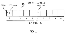
図2は、OFDMを基にしたLTEダウンリンクの無線フレーム201を説明する概要図を示す。LTEダウンリンクの無線フレームは、LTE基地局(改良されたNode B、「eNodeB」または「eNB」として様々知られ、これらの用語は同義である)から送信され、10ms持続する。ダウンリンクの無線フレームは、10個のサブフレームを備え、各サブフレームは1ms持続する。プライマリ同期信号(PSS)およびセカンダリ同期信号(SSS)は、LTEフレームの第1および第6のサブフレームにおいて送信される。プライマリブロードキャストチャネル(PBCH)は、LTEフレームの第1のサブフレームにおいて送信される。PSS、SSS、およびPBCHは、より詳細に以下に議論される。
FIG. 2 shows a schematic diagram illustrating an LTE
図3は、従来のダウンリンクのLTEサブフレーム例の構造を説明するグリッドの概要図である。サブフレームは、1msの期間に渡り送信される所定の数の「シンボル」を有する。各シンボルは、ダウンリンクの無線キャリアの帯域幅の全域にわたって分散された、所定の数の直交サブキャリアを有する。ここで、水平軸は、時間を表し、垂直は周波数を表す。 FIG. 3 is a schematic diagram of a grid illustrating a structure of a conventional downlink LTE subframe example. A subframe has a predetermined number of “symbols” transmitted over a period of 1 ms. Each symbol has a predetermined number of orthogonal subcarriers distributed throughout the bandwidth of the downlink radio carrier. Here, the horizontal axis represents time and the vertical represents frequency.
図3において示されるサブフレーム例は、14のシンボルおよび20MHzの帯域幅、R320にわたって分散する1200のサブフレームを有する。LTEにおける送信のためのユーザデータの最も小さい割当は、1スロット(0.5サブフレーム)にわたり送信される12個のサブキャリアを有する「リソースブロック」である。図3におけるサブフレームグリッド中の各個のボックスは、1のシンボルで送信される12のサブキャリアに対応し、したがって、図3中の単一の行は2個のリソースブロックに対応する。
The example subframe shown in FIG. 3 has 1200 subframes distributed over
制御データは、リソースブロックより小さいユニット中に割り当てられ得、LTEにおける送信のための最小の割当は、「リソースエレメント」である。用語「リソースエレメント」は、1のシンボルにおける1のサブキャリア上のデータを言う。リファレンス信号などの制御データは、リソースブロック内の特定のリソースエレメントに割り当てられ得る。 Control data may be allocated in units smaller than resource blocks, and the smallest allocation for transmission in LTE is a “resource element”. The term “resource element” refers to data on one subcarrier in one symbol. Control data such as a reference signal may be assigned to a specific resource element in the resource block.
図3は、4つのLTE端末に対する準備段階のリソース割当て340、341、342、343を示す。例えば、第1のLTE端末(UE1)に対するリソース割当て342は、12のサブキャリアの5のブロック(すなわち60のサブキャリア)にまたがって広がっており、第2のLTE端末(UE2)に対するリソース割当て343は12のサブキャリアの6のブロックにまたがって広がっている、等である。
FIG. 3 shows
制御チャネルデータは、サブフレームの第1のnシンボルを有するサブフレームの制御領域300(図3において点のシェーディングにより示される)において送信され、nは3MHzまたは3MHzより大きいチャネル帯域幅に対して1から3のシンボル間で変化し得、nは1.4MHzのチャネル帯域幅について2から4のシンボル間で変化し得る。明確な例を提供するために、次の記載は、nの最大値を3とするように3MHzまたは3MHzより大きいチャネル帯域幅のホストキャリアに関係する。制御領域300において送信されるデータは、物理下り制御チャネル(PDCCH)、物理制御フォーマット指示チャネル(PCFICH)および物理HARQ指示チャネル(PHICH)上で送信されるデータを含む。
Control channel data is transmitted in a subframe control region 300 (shown by dot shading in FIG. 3) having the first n symbols of the subframe, where n is 1 for channel bandwidths greater than 3 MHz or 3 MHz. N can vary between 2 and 4 symbols, and n can vary between 2 and 4 symbols for a channel bandwidth of 1.4 MHz. In order to provide a clear example, the following description relates to a host carrier with a channel bandwidth of 3 MHz or greater than 3 MHz so that the maximum value of n is 3. The data transmitted in the
PDCCHは、サブフレームのどのシンボル上のどのサブキャリアが特定のLTE端末に割当てられているかを示す制御データを含む。そのため、図3で示されるサブフレームの制御領域300において送信されるPDCCHデータは、UE1は参照番号342により特定されるリソースの領域に割当てられ、UE2は参照番号343により特定されるリソースの領域に割当てられた、などを示し得る。
PDCCH includes control data indicating which subcarrier on which symbol of the subframe is allocated to a specific LTE terminal. Therefore, the PDCCH data transmitted in the
PCFICHは、制御領域のサイズ(すなわち、1.4MHzのチャネル帯域幅の場合、1から3の間のシンボルまたは2から4)を示す制御データを含む。
PHICHは、前に送信されたアップリンクデータがネットワークによって首尾よく受信されたか否かを示すHARQ(ハイブリッド自動再送要求)データを含む。
The PCFICH includes control data indicating the size of the control region (ie, between 1 and 3 symbols or 2 to 4 for a 1.4 MHz channel bandwidth).
The PHICH includes HARQ (Hybrid Automatic Repeat Request) data that indicates whether the previously transmitted uplink data has been successfully received by the network.
時間周波数リソースグリッドの中央帯310におけるシンボルは、プライマリ同期信号(PSS)、セカンダリ同期信号(SSS)およびプライマリブロードキャストチャネル(PBCH)を(第1および第6のサブフレームにおいて)含む情報の送信に使われる。この中央帯310は、概して72のサブキャリアの広さ(1.08MHzの送信帯域幅に相当)である。PSSおよびSSSは、一旦検出されると、LTE端末デバイスにフレーム、サブフレーム、スロットおよびシンボル同期を得ることを可能とし、ダウンリンク信号を送信する改良されたNode Bのセル識別(PCI)を決定する同期信号である。PBCHは、LTE端末がセルに適切にアクセスするために使用するパラメータを含むマスタ情報ブロック(MIB)を含むセルの情報を運ぶ。物理下り共有チャネル(PDSCH)上で個別のLTE端末に送信されるデータは、サブフレームの他のリソースエレメントにおいて送信され得る。これらのチャネルのさらなる説明は、以下に提供される。
The symbols in the
図3はまた、システム情報を含み、R344の帯域幅に広がるPDSCH 344の領域を示す。従来のLTE無線フレーム内のサブフレームにわたって分布するリファレンス信号(RS)があるであろう:これらは、さらに以下で議論されるが、明確性の理由から図3において示されていない。
Figure 3 also includes a system information indicates an area of a
マシーンタイプコミュニケーション(MTC)デバイス
上述したように、第3および第4世代ネットワークの予想される広範な配備は、利用可能な高いデータレートを利用するよりはむしろ代わりに、強固な無線インターフェースおよびカバレッジエリアの拡大する偏在性を利用するデバイスおよびアプリケーションのクラスの並列開発を導いた。このデバイスおよびアプリケーションの並列なクラスは、MTCデバイスおよびいわゆるマシンツーマシン(M2M)アプリケーションを含み、ここで準自律的または自律的なワイヤレス通信デバイスは、典型的に比較的低頻度の基準で少量のデータを通信する。
Machine Type Communication (MTC) Device As noted above, the expected widespread deployment of 3rd and 4th generation networks is instead a robust radio interface and coverage area rather than utilizing the high data rates available. Led to the parallel development of classes of devices and applications that take advantage of the growing ubiquity of This parallel class of devices and applications includes MTC devices and so-called machine-to-machine (M2M) applications, where quasi-autonomous or autonomous wireless communication devices are typically small quantities on a relatively infrequent basis. Communicate data.
MTC(およびM2M)デバイスの例は:例えば、消費者の家に設置され、消費者のガス、水道、電気などの消費者の公共サービスの消費に関するデータを中央MTCサーバデータに定期的に情報を返信する、いわゆるスマートメータ;輸送および物流追跡、道路通行料徴収および監視システムなどの「追跡(track and trace)」アプリケーション;MTC対応センサ、照明、診断器具などを有する遠隔保守および制御システム;環境モニタリング;店頭支払いシステムおよび自動販売機;セキュリティシステムなどを含む。 Examples of MTC (and M2M) devices are: for example, installed in a consumer's home and periodically providing information about consumer public service consumption such as gas, water, and electricity to central MTC server data. Reply, so-called smart meters; “track and trace” applications such as transportation and logistics tracking, road toll collection and monitoring systems; remote maintenance and control systems with MTC-compatible sensors, lighting, diagnostic equipment, etc .; environmental monitoring ; Over-the-counter payment systems and vending machines; including security systems.
MCT型デバイスの特徴についてのさらなる情報およびMTCデバイスが適用し得るアプリケーションのさらなる例は、例えば、ETSI TS 122 368 V10.530(2011−07)/3GPP TS 22.368 バージョン 10.5.0 リリース10[1]などの対応する標準において見出される。
More information about the characteristics of MCT-type devices and further examples of applications that MTC devices may apply are, for example, ETSI TS 122 368 V10.530 (2011-07) / 3GPP TS 22.368 version 10.5.0
MTC型端末などの端末にとって第3または第4世代モバイル電気通信ネットワークにより提供される広いカバレッジエリアを使用することは都合がよくなり得るものの、現在、達成した配備に対する不利益および試みが存在する。スマートフォンなどの従来の第3または第4世代端末デバイスとは異なり、MTC型端末は好ましくは比較的単純であり安価である:加えてMTCデバイスは、しばしば直接の保守および交換のためには容易にアクセスをする余裕のない状況において配備される‐信頼性があり、効率的な動作が重大であり得る。さらにMTC型端末によって行われる機能のタイプ(例えばデータを収集し折り返し報告する)は、実行するのに特に複雑な処理を必要としない一方で、第3および第4世代モバイル電気通信ネットワークは、実行するのにより複雑で高価な無線送受信機を必要とする高度なデータ変調技術(16QAMまたは64QAMなど)を典型的に無線インターフェース上で採用する。 While it may be convenient for terminals such as MTC type terminals to use the large coverage area provided by third or fourth generation mobile telecommunications networks, there are currently disadvantages and attempts to the achieved deployment. Unlike traditional 3rd or 4th generation terminal devices such as smartphones, MTC type terminals are preferably relatively simple and inexpensive: In addition, MTC devices are often easy for direct maintenance and replacement Deployed in situations where access cannot be afforded-reliable and efficient operation can be critical. In addition, the type of function performed by the MTC-type terminal (eg, collecting data and reporting back) does not require particularly complex processing to perform, while third and fourth generation mobile telecommunications networks perform Advanced data modulation techniques (such as 16QAM or 64QAM) that typically require more complex and expensive wireless transceivers are typically employed on the wireless interface.
スマートフォンは、典型的なスマートフォン型の機能を実行するために強力なプロセッサを典型的に必要とするため、スマートフォン中にそのような複雑な送受信機を含めることが大抵正当化される。しかしながら、上で示したように、現在、LTE型ネットワークを用いて通信するための比較的低廉でより複雑でないデバイスを使用するという要求がある。異なる動作機能を有するデバイスへのネットワークアクセシビリティ、例えば縮小された帯域幅動作、を提供するというこの原動力と並行して、そのようなデバイスをサポートする電気通信システムにおける利用可能な帯域幅の使用を最適化するという要求がある。 Because smartphones typically require a powerful processor to perform typical smartphone-type functions, it is often justified to include such complex transceivers in the smartphone. However, as indicated above, there is currently a need to use relatively inexpensive and less complex devices for communicating using LTE networks. In parallel with this driving force to provide network accessibility to devices with different operating capabilities, such as reduced bandwidth operation, optimize the use of available bandwidth in telecommunications systems that support such devices There is a request to make it.
多くの状況において、全キャリア帯域幅にわたるLTEダウンリンクフレームからデータを受信し処理(制御)することのできる従来の高性能LTE受信機ユニットをこれらのような低ケイパビリティ端末に提供することは、少量のデータを通信する必要のみあるデバイスにとって過度に複雑であり得る。これは、したがって、LTEネットワークにおける低ケイパビリティMTC型デバイスの広範な配備の実用性を制限し得る。その代わりに、MTCデバイスなどの低ケイパビリティ端末に、端末へ送信されそうなデータの量により釣り合った、より単純な受信機ユニットを提供することが好ましい。 In many situations, providing low performance terminals such as these with conventional high performance LTE receiver units capable of receiving and processing (controlling) data from LTE downlink frames over the entire carrier bandwidth is a small amount. Can be overly complex for devices that only need to communicate their data. This may therefore limit the utility of wide deployment of low capability MTC type devices in LTE networks. Instead, it is preferable to provide a lower capability terminal, such as an MTC device, with a simpler receiver unit that is more balanced by the amount of data likely to be transmitted to the terminal.
仮想キャリア概念
MTCデバイスなどの低ケイパビリティ端末に調整された「仮想キャリア」は、したがって、従来のOFDM型ダウンリンクキャリア(すなわち「ホストキャリア」)の送信リソース内に提供される。従来のOFDM型ダウンリンクキャリア上で送信されるデータとは異なり、仮想キャリア上で送信されるデータは、ホストOFDMキャリアの全帯域幅を処理することを必要とすることなく受信され、復号されることができる。したがって、仮想キャリア上で送信されるデータは、複雑さが低減された受信機ユニットを用いて受信され、復号されることができる。
A “virtual carrier” tailored to a low capability terminal, such as a virtual carrier concept MTC device, is thus provided within the transmission resources of a conventional OFDM type downlink carrier (ie, “host carrier”). Unlike data transmitted on a conventional OFDM type downlink carrier, data transmitted on a virtual carrier is received and decoded without requiring processing of the full bandwidth of the host OFDM carrier. be able to. Thus, data transmitted on the virtual carrier can be received and decoded using a receiver unit with reduced complexity.
用語「仮想キャリア」は、本質的に、OFDMに基づく無線アクセス技術(WiMAXまたはLTEなど)のためのホストキャリア内のMTC型デバイスのための狭帯域の割当に対応する。
仮想キャリア概念は、多数の同時係属特許出願(英国特許出願1101970.0[2]、英国特許出願1101981.7[3]、英国特許出願1101966.8[4]、英国特許出願1101983.3[5]、英国特許出願1101853.8[6]、英国特許出願1101982.5[7]、英国特許出願1101980.9[8]および英国特許出願1101972.6[9]を含む)において記載されており、その文脈は参照によりここに組み込まれる。しかしながら、参照しやすいように、付属文書1において仮想キャリアの概念のある側面の概説が提示されている。
The term “virtual carrier” essentially corresponds to narrowband allocation for MTC-type devices in a host carrier for OFDM-based radio access technologies (such as WiMAX or LTE).
The virtual carrier concept is based on a number of co-pending patent applications (UK patent application 1101970.0 [2], UK patent application 11019817 [3], UK patent application 1101966.8 [4], UK patent application 11019833 [5]. UK patent application 1101853.8 [6], UK patent application 1101982.5 [7], UK patent application 1101980.9 [8] and UK patent application 1101972.6 [9]), The context is hereby incorporated by reference. However, for ease of reference,
上で説明したように、LTEなどのOFDMに基づくモバイル通信システムにおいて、ダウンリンクデータは、サブフレーム基準でサブフレーム上の異なるサブキャリア上で送信されるように動的に割り当てられる。したがって、サブフレーム毎において、ネットワークは、どのシンボル上のどのサブキャリアがどの端末へ関連するデータを含むかについて、信号で伝える(すなわちダウンリンク許可シグナリング)。 As described above, in OFDM-based mobile communication systems such as LTE, downlink data is dynamically assigned to be transmitted on different subcarriers on a subframe on a subframe basis. Thus, for each subframe, the network signals which subcarrier on which symbol contains data associated with which terminal (ie, downlink grant signaling).
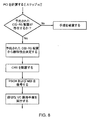
セル獲得のための初期手順
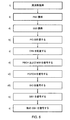
セルを初期に獲得するためのUEにより従われる手順は、英国特許出願1113801.3[10](また「キャンプオン」プロセスとして言及される)において詳細に議論されてきており、このためここでは詳細には取り扱われない。手順は、以下のように要約される:
Initial Procedure for Cell Acquisition The procedure followed by the UE to initially acquire a cell has been discussed in detail in UK patent application 1113801.3 [10] (also referred to as the “camp-on” process). For this reason, it is not dealt with in detail here. The procedure is summarized as follows:
i)周波数獲得。
ii)プライマリ同期信号獲得(サブフレーム、スロットおよびシンボルのタイミング獲得、セカンダリ同期信号スクランブルコード獲得)。
iii)セカンダリ同期信号獲得(フレームタイミング獲得、セルグループIDシーケンス獲得)。
iv)PSSおよびSSSから物理層セル識別(PCI)が計算されることができる。
v)PCIからセル固有リファレンス信号(CRS)位置が決定されることができる。
i) Frequency acquisition.
ii) Acquisition of primary synchronization signal (acquisition of subframe, slot and symbol timing, acquisition of secondary synchronization signal scramble code).
iii) Secondary synchronization signal acquisition (frame timing acquisition, cell group ID sequence acquisition).
iv) Physical layer cell identification (PCI) can be calculated from PSS and SSS.
v) The cell specific reference signal (CRS) position can be determined from the PCI.
vi)PBCHおよびMIBを復号する。
vii)PCFICHを復号し、PDCCHにいくつのシンボルが割り当てられているかを決定する。
viii)PDCCHからSIB 1についてのDCIを復号する。
ix)SIB 1を復号し、他のSIBについてのスケジュール情報を得る。
x)SIB(SIB 1以外)を復号する。
これらのステップは、図5において説明されている。
vi) Decode PBCH and MIB.
vii) Decode PCFICH to determine how many symbols are assigned to PDCCH.
viii) Decode DCI for
ix)
x) Decode SIB (other than SIB 1).
These steps are illustrated in FIG.
セル識別
LTEにおいて、各セルは、関連付けられた物理層セル識別(PCI)を有する。それぞれが3つの識別を含む168グループに纏められた504のPCIがある。これらは、‐FDDにおける各セル中のLTEフレームの第1および第6のサブフレームにおいて送信される‐プライマリおよびセカンダリ同期シーケンス(PSSおよびSSS)の組み合わせを処理することにより抽出される:PSSはPCIのグループ内の3つの識別の1つを推定するのに用いられ、SSSは168グループの1つを推定するのに用いられる(図5におけるステップiv))。従来のLTEネットワークは、PCIが、PSS/SSS送信において組み込まれた際に、周波数再利用率1を用いた配置においてUEに異なるセル識別を検出させる良好な非相関特性を有するため、セルID基準で計画されている。
In cell identification LTE, each cell has an associated physical layer cell identification (PCI). There are 504 PCIs organized into 168 groups, each containing three identifications. They are extracted in the first and sixth subframes of the LTE frame in each cell in FDD-extracted by processing a combination of primary and secondary synchronization sequences (PSS and SSS): PSS is PCI And SSS is used to estimate one of the 168 groups (step iv in FIG. 5)). Conventional LTE networks have good decorrelation characteristics that allow the UE to detect different cell identities in deployments with frequency reuse factor of 1 when PCI is incorporated in PSS / SSS transmission, so cell ID criteria Planned with.
リファレンス信号
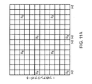
3GPP TS 36.211(バージョン 11.0.0)は、eNodeB(eNB)により送信され得る種々のダウンリンクリファレンス信号(RS)を特定する:以下の議論において特に興味深いのは、セル固有リファレンス信号(CRS)およびチャネル状態情報リファレンス信号(CSI−RS)である。各RSは、アンテナポートのサブセットを利用する。アンテナポートは、アンテナのタイプに応じて異なる方法で物理的アンテナに位置づけられる:それにもかかわらず、アンテナポートは、UEの視点からは、ダウンリンク送信を表す。
The reference signal 3GPP TS 36.211 (version 11.0.0) identifies various downlink reference signals (RS) that may be transmitted by the eNodeB (eNB): Of particular interest in the following discussion is the cell specific reference A signal (CRS) and a channel state information reference signal (CSI-RS). Each RS utilizes a subset of antenna ports. Antenna ports are positioned on physical antennas differently depending on the type of antenna: Nevertheless, antenna ports represent downlink transmissions from the UE perspective.
関連する3GPP標準のリリース8(およびそれ以降)は、セル固有リファレンス信号(CRS)を必要とする。CRSは、4つまでのアンテナポート(ポート0〜3)について定義され、サブフレーム毎およびリソースブロック毎においてセル中でブロードキャストされる。CRSを生成するのに用いられる擬似ランダムシーケンスは、少なくともセルのPCIの関数である(3GPP TS 36.211においてセクション6.10.1.1に記載される)。 The related 3GPP standard Release 8 (and later) requires a cell specific reference signal (CRS). CRS is defined for up to four antenna ports (ports 0-3) and is broadcast in the cell every subframe and per resource block. The pseudo-random sequence used to generate the CRS is at least a function of the cell's PCI (described in section 6.10.1.1 in 3GPP TS 36.211).
さらに、現在のシステムにおいて、与えられたアンテナポート上のCRSは、サブフレーム毎の同一のOFDMシンボルにおいて送信されるが、これらが送信されるリソースブロック中のサブキャリアは、基準位置からオフセットしている。図11は、νshift=0についての4つまでのアンテナポート上のCRS位置を示す。オフセットは、以下の方程式に従い‐図11のリファレンス信号の位置における垂直シフトに対応する:
νshift=NID CELL mod 6
ここで、NID CELLは、PCIである(図は、3GPP TS 36.211に由来する)。言い換えると、サブキャリアの垂直シフトは、PCIの関数である(これは図11においては示されていないが、3GPP TS 36.211においてセクション6.10.1.2に記載されている)。
Furthermore, in current systems, CRS on a given antenna port is transmitted in the same OFDM symbol per subframe, but the subcarriers in the resource block in which they are transmitted are offset from the reference position. Yes. FIG. 11 shows CRS positions on up to four antenna ports for ν shift = 0. The offset corresponds to the vertical shift in the position of the reference signal in FIG. 11 according to the following equation:
ν shift = N ID CELL mod 6
Here, N ID CELL is PCI (the figure is derived from 3GPP TS 36.211). In other words, the vertical shift of the subcarrier is a function of PCI (this is not shown in FIG. 11 but is described in section 6.10.1.2 in 3GPP TS 36.211).
リリース10および引き続く3GPP標準は、eNBにより送信され得る他のRS:チャネル状態情報リファレンス信号(CSI−RS)を導入する。CSI−RSは、8つまでのアンテナポート(ポート15〜22)について定義され、別の面ではPDSCHに割り当てられる(図3参照)サブフレーム内のリソースエレメントを占有し、したがって有意義なチャネル品質測定を提供するのに有用である。
SCI−RSの配置は、無線リソース制御シグナリング(RRC)を介してUEにシグナリングされ、以下を含む、TS 36.311を参照:
・UEがCSI−RSが存在すると推定し得るリソースエレメントの配置(CSI−RS配置)−標準は、32のこのような配置を規定し、各サブフレームに14のシンボルがある;
SCI-RS deployment is signaled to the UE via Radio Resource Control Signaling (RRC), see TS 36.311, including:
Resource element arrangement that the UE can assume that CSI-RS is present (CSI-RS arrangement)-the standard defines 32 such arrangements, with 14 symbols in each subframe;
・UEがCSI−RSが実際に送信されると推定し得るサブフレームの配置(CSI−RSサブフレーム配置)−サブフレーム配置は、CSI−RSが送信される周期、および、SCI−RSが送信されるサブフレームが、システムフレーム番号(SFN)=0での無線フレームの先頭に対してオフセットするサブフレームの数を定義する;および
・使用中のCSI−RSアンテナポートの数;1、2、4または8。
Subframe arrangement in which the UE can estimate that CSI-RS is actually transmitted (CSI-RS subframe arrangement)-Subframe arrangement is a period in which CSI-RS is transmitted, and SCI-RS is transmitted Defines the number of subframes for which the subframe is offset relative to the beginning of the radio frame with system frame number (SFN) = 0; and the number of CSI-RS antenna ports in use; 4 or 8.
CSI−RSにおいて送信されるシーケンスは、仕様に定義される疑似ランダムシーケンス生成器によってもたらされる。この生成器の初期設定は、PCIに依存し、したがって送信されるシーケンスは、PCIの関数である。 The sequence transmitted in CSI-RS is provided by a pseudo-random sequence generator defined in the specification. The default setting of this generator depends on the PCI, so the transmitted sequence is a function of the PCI.
リファレンス信号への摂動(perturbataions)
セル獲得を試みるUEにeNodeBのケイパビリティに関する適時の情報を提供するために、セルによって送信されるRSの内容または位置へのある「摂動」が、VC動作の利用可能性または構成などのセルのケイパビリティまたは構成に関する情報を暗示するまたは表すのに用いられ得ることが認識されてきた。今後互換的に使用される用語「通信パラメータ」および「静特性」は、両方ともセルのケイパビリティおよび構成を包含する。
Perturbataions to the reference signal
In order to provide timely information regarding eNodeB capabilities to UEs attempting cell acquisition, certain “perturbations” to the content or location of the RS transmitted by the cell may cause cell capabilities such as availability or configuration of VC operation. Or it has been recognized that it may be used to imply or represent information about the configuration. The terms “communication parameters” and “static characteristics” used interchangeably in the future both encompass cell capabilities and configurations.
上述したように、使用されるRSの内容は典型的にセルのPCIに基づいており、したがってある実施形態においてある識別可能なRSリソースにより搬送されるPCIが変化し、またはRSが「予期されない」リソースにおいて送信され、これらの送信およびセルの実際のPCIおよび/または「予期された」RS送信リソースの間の種々の関係はVC配置情報を搬送する。 As noted above, the RS content used is typically based on the PCI of the cell, and thus in some embodiments the PCI carried by some identifiable RS resource changes or the RS is “unexpected”. Various relations between these transmissions and the actual PCI and / or “expected” RS transmission resources of the cell transmitted in the resource carry VC placement information.
本実施形態は、UEが適当なシグナリング、例えばRRCシグナリングをセルから受信することができる前に動作するため、eNodeBは、セルにおいてこのような摂動の利用に関してUEを直接的に構成するすべがない:言い換えると、これらの実施形態の動作は、UEに対しトランスペアレントである。結果として、リファレンス信号への摂動の適用は、また、標準仕様において摂動を関連付けることにより、通信パラメータの他のタイプを、例えばその関連付に従ってセル送信を解釈する特定のUEカテゴリおよび関連するカテゴリのUEのみへ示すために実行され得る。容易に理解されるように、ネットワークオペレータは、適切な方法により彼らのネットワークのこれらの側面を計画する必要があるであろう。 Since this embodiment operates before the UE can receive appropriate signaling, eg, RRC signaling, from the cell, the eNodeB should not configure the UE directly for the use of such perturbations in the cell : In other words, the operation of these embodiments is transparent to the UE. As a result, the application of perturbations to the reference signal also relates other types of communication parameters by relating perturbations in the standard specification, e.g. for certain UE categories and related categories that interpret cell transmissions according to their associations. Can be executed to show only to the UE. As will be readily appreciated, network operators will need to plan these aspects of their network in an appropriate manner.
我々は、今、セルにおける仮想キャリア(VC)ケイパビリティの表示に関するある例示的な実施形態を記述する。UEへの参照は、したがって、他に示されない限り、VC上での動作をサポートするUEへのものである。 We now describe one exemplary embodiment for displaying virtual carrier (VC) capabilities in a cell. A reference to a UE is therefore to a UE that supports operation on a VC unless otherwise indicated.
CSI−RSアイデンティティ分割によるVC構成の表示
図7に説明される第1の実施形態において、セルの与えられたケイパビリティは、予約されたCSI−RS配置上で送信されるリファレンス信号が生成される方法を置き換える(「摂動する」)ことにより、マークを付され得る。必要に応じてTS 36.211の表6.10.5.2−1または表6.10.5.2−2におけるCSI−RS配置のうち少なくとも1つは、摂動の適用における使用のために予約されている。これの予約されたリソース配置において、リファレンス信号が、セルのPCI以外のPCIに基づいたリファレンス信号生成シーケンスの開始と同時に、送信される:典型的に「不適合なPCI」は、これからUEが送信信号を受信しそうな、地理的に付近にある任意のセルに関連付けられていない予約されたPCIであるか、または全体のネットワークにおいて予約されたPCIである。これは、TS 36.211のセクション6.10.5.1におけるシーケンス生成のための方程式において、量nIDが、セルのPCI、NID cellと異なることを意味する。以下に再現されるCinitについての結果として生じる式において、両方の出現においてnIDは、予約されたPCI値、NID cellと置き換えられる:
Cinit=210・(7・(ns+1)+l+1)・(2・nID+1)+2・nID+NCP。
Display of VC Configuration with CSI-RS Identity Division In the first embodiment illustrated in FIG. 7, the given capability of the cell is the method by which the reference signal transmitted on the reserved CSI-RS arrangement is generated. Can be marked by replacing ("perturbs"). As required, at least one of the CSI-RS configurations in TS 66.211 Table 6.10.5-2-1 or Table 6.10.5-2-2 is for use in perturbation applications. Reserved. In this reserved resource arrangement, a reference signal is transmitted at the same time as the start of a reference signal generation sequence based on a PCI other than the PCI of the cell: typically “non-compliant PCI” Is a reserved PCI that is not associated with any geographically nearby cell or that is reserved in the entire network. This means that in the equation for sequence generation in section 6.10.5.1 of TS 36.211, the quantity n ID is different from the cell PCI, N ID cell . In the resulting expression for C init reproduced below, in both occurrences, n ID is replaced with the reserved PCI value, N ID cell :
C init = 2 10 · (7 · (n s +1) + l + 1) · (2 · n ID +1) +2 · n ID + N CP.
UEは、どの組み合わせが使用中であるかを決定するために、各予約されたPCI値とともに各潜在的に予約されるCSI−RS配置を検索する必要があるであろう。したがって、予約されたセットをできる限り小さく維持することが好ましいともいえる。 The UE will need to search each potentially reserved CSI-RS configuration along with each reserved PCI value to determine which combination is in use. Therefore, it may be preferable to keep the reserved set as small as possible.
これに続くケイパビリティ検出プロセスの変形は、以下のステップを含み、ここに特定の順序なしに提示する:
1.予約されたCSI−RS配置における予約されたまたは不適合のPCIの存在は、それ自身において、またはPSS/SSSにおいて通信されるセルの実際のPCIへの参照による、VCの静特性を暗示する。
Subsequent variations of the capability detection process include the following steps, presented here in a specific order:
1. The presence of reserved or non-conforming PCI in the reserved CSI-RS deployment implies the static characteristics of the VC, either by itself or by reference to the actual PCI of the cell being communicated in the PSS / SSS.
2.予約されたCSI−RS配置における予約されたまたは不適合のPCIの存在は、それが見出される配置と共同してVCの静特性を暗示する。
3.1よりも多い予約されたCSI−RS配置がある場合、これらは、送信するセルのものと異なりおよび互いに異なる、異なる(予約されたまたは不適合の)PCIを含み得、このような組み合わせは送信するセルの異なる静特性を表す。
以上のこの実施態様の変形は、組み合わせられ得る。
2. The presence of a reserved or non-conforming PCI in a reserved CSI-RS configuration implies the static characteristics of the VC in conjunction with the configuration in which it is found.
If there are more than 3.1 reserved CSI-RS deployments, these may contain different (reserved or non-conforming) PCIs that are different from and different from those of the transmitting cell, such combinations It represents the different static characteristics of the transmitting cell.
The above variations of this embodiment can be combined.
この実施形態において使用されるように、PCI値は、静特性の状態または値に対し個別にマッピングされ得る。あるいは、PCI値のグループ(また「区分」ともいう)は、このような状態または値と関連付けられる。
移動体通信事業者(MNO)は、セルがセル付近の予約されたCSI−RS配置において使用中である同一のPCIをこれらの実際の識別として送信しないようにセルIDを計画する必要があるであろう。
As used in this embodiment, PCI values may be individually mapped to static state or values. Alternatively, a group of PCI values (also referred to as a “partition”) is associated with such a state or value.
The mobile operator (MNO) needs to plan the cell ID so that the cell does not transmit the same PCI that is in use in the reserved CSI-RS deployment near the cell as their actual identity. I will.
その状態または値が特定のリファレンス信号配置における特定のPCI(またはPCI区分)の存在により表示され得る静特性の例は以下を含む:
・セルがVCを送信しているまたは送信できるか否か。
・全てのVC UEが最初に復号を試みるべき主要なVCの周波数領域における位置。
Examples of static characteristics whose state or value may be indicated by the presence of a specific PCI (or PCI segment) in a specific reference signal arrangement include:
Whether the cell is sending or can send VCs.
The location in the frequency domain of the main VC where all VC UEs should first try to decode.
・区分は、CSI−RS配置などのセルにおけるVC動作に固有のリファレンス信号配置の静的エレメントを表示し得る。
・UEは、インストール/製造時に、例えば一般的なネットワーク負荷が低減される夜に、ある区分に属するPCIを送信するセル上の無線アクセスを優先するようにあらかじめ構成され得る。このようなUEは、ネットワークからリソースを要求するかを決定する際に、この情報を考慮し得る。これは一般に、そのデータが頻繁には時間で区切られていないMTCデバイスに関する。
・セルが、UEがセル上の適したトラフィック負荷のいくらか早期の表示を有し得るようにネットワーク共有を動作させているか。
The partition may indicate a static element of the reference signal arrangement specific to VC operation in the cell, such as CSI-RS arrangement.
-The UE may be pre-configured during installation / manufacturing to prioritize radio access on cells that transmit PCIs belonging to a segment, for example at night when general network load is reduced. Such a UE may consider this information when determining whether to request resources from the network. This generally relates to MTC devices whose data are not frequently separated by time.
• Is the cell operating network sharing so that the UE may have some early indication of the appropriate traffic load on the cell.
一例において、予約されたCSI−RS配置において第1の区分から不適合なPCIを送信するセルが、UEによりVC動作をサポートしないと推定され得る一方で、第2の区分からPCIを送信するセルが、UEによりVC動作をサポートすると推定され得る。VC準拠セル内においてのみ動作可能なUEは、セルがVCをサポートせず他のセルを獲得しようと試みない場合において初期手順を放棄する必要があるであろう。VC準拠セル内においてのみならずVC非準拠セル内において任意に動作可能なUEは、セルを放棄するか続けるかに関する実行の選択が残されるであろう。予約されたCSI−RS配置における第1の区分からの不適合なPCIの送信の意義を意識しないUEは、単純に従来の初期手続きを続けるであろう。 In one example, a cell that transmits non-conforming PCI from the first partition in a reserved CSI-RS deployment may be estimated not to support VC operation by the UE, while a cell that transmits PCI from the second partition It can be estimated that the UE supports VC operation. A UE that can only operate in a VC-compliant cell will need to abandon the initial procedure if the cell does not support VC and does not attempt to acquire another cell. A UE that can optionally operate in a non-VC cell as well as in a VC compliant cell will be left with the choice of performing on whether to abandon or continue the cell. A UE that is unaware of the significance of sending non-conforming PCI from the first partition in the reserved CSI-RS deployment will simply continue with the traditional initial procedure.
CSI−RS配置、PCIおよびVCの存在または不在などの静特性の間の関連は、仕様において定義され得、本実施形態に係るネットワークの配備は、セルIDが正確に割り当てられることを保証するためにMNOによる計画を必要とするであろう。 The association between static characteristics such as CSI-RS placement, PCI and VC presence or absence can be defined in the specification, and the deployment of the network according to this embodiment to ensure that the cell ID is assigned correctly. Will need a plan by MNO.
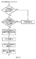
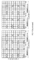
図7は、第1の実施形態に係る動作可能な端末のためのUE手順における差を説明する。「適切なVC獲得手順」は、どのVCの実行がセルにおいて使用されているか、および/またはUEにより知られているかによって決まる。UEが与えられたセル上での手続きを破棄することを決定すべきであれば、代わりのセル上で手順が再度開始することが予期されるであろう。このような代わりのセル上で、UEは、UEが例えば隣接したセル上での無線資源管理(RRM)測定を行うことができるように、すでに通常のPCIを決定する限りにおいて進み得る。 FIG. 7 illustrates a difference in UE procedure for an operable terminal according to the first embodiment. The “appropriate VC acquisition procedure” depends on which VC implementation is used in the cell and / or known by the UE. If the UE should decide to discard the procedure on a given cell, it will be expected that the procedure will start again on the alternative cell. On such an alternative cell, the UE may proceed as long as it already determines the normal PCI so that the UE can make radio resource management (RRM) measurements on neighboring cells, for example.
したがって、システムは、通信を行うセルのPCI値へ、異なるPCI値とともに予約されたCSI−RSを送信する概念を導入し、ここでこの異なるPCI値は、セルのPCIと連動してまたは単独でセルの通信信号および/またはケイパビリティの性質に関する情報を暗示する。 Thus, the system introduces the concept of transmitting a reserved CSI-RS with a different PCI value to the PCI value of the communicating cell, where the different PCI value can be linked to the PCI of the cell or alone. Implies information regarding the nature of the cell's communication signals and / or capabilities.
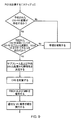
CSI−RS配置によるVC配置の表示‐分割のみ
図8において説明される第2の実施形態は、第1の実施形態との類似点を有している:セルの通常のPCIを用いて生成されるリファレンスシンボルスクランブリングシーケンスが、予約されたCSI−RS配置において常に送信され、(不適合なPCIは使用されず)および静特性が単にUEが検出する予約されたCSI−RS配置により表示される点で異なる。したがって、UEは、予約された配置の1以上がセルにより送信されているかを確かめるために、予約された配置の特定のセットの中から検索することができ、したがって静特性を推測する。CSI−RS配置は、ネットワークオペレータにより計画され得、したがってこの実施形態は、容易に実現され、適当なネットワーク設計によりセル間干渉が回避されることができる。
Display of VC arrangement by CSI-RS arrangement-partitioning only The second embodiment described in FIG. 8 has similarities to the first embodiment: generated using the normal PCI of the cell The reference symbol scrambling sequence is always transmitted in the reserved CSI-RS configuration (no non-conforming PCI is used) and static characteristics are simply indicated by the reserved CSI-RS configuration detected by the UE It is different. Thus, the UE can search among a particular set of reserved configurations to ascertain whether one or more of the reserved configurations are being transmitted by the cell, and thus infer static characteristics. The CSI-RS deployment can be planned by the network operator, so this embodiment is easily implemented and inter-cell interference can be avoided with proper network design.
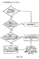
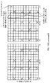
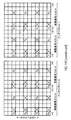
CSI−RSサブフレーム配置によるVC配置の表示
図9および10においてそのバージョンが説明される第3の実施形態は、少なくとも1つの予約されたCSI−RS配置が使用される点で、上の第1および第2の実施形態と同一の経路をたどる。しかしながら、この実施形態においては、静特性は前記(または各々の)予約されたCSI−RS配置に関連付けられたサブフレームCSI−RS配置により示されることができる。
Display of VC Arrangement with CSI-RS Subframe Arrangement The third embodiment, the version of which is illustrated in FIGS. 9 and 10, is the first one above in that at least one reserved CSI-RS arrangement is used. And the same route as the second embodiment is followed. However, in this embodiment, static characteristics may be indicated by a subframe CSI-RS arrangement associated with the (or each) reserved CSI-RS arrangement.
図9において説明される第3の実施形態のバージョンでは、検出されるCSI−RS配置は、まず配置が予約されているか、そうであれば予約されたCSI−RS配置に関連付けられたサブフレームCSI−RS配置がVCケイパビリティを暗示するかを確認するために検査される。このバージョンでは、(限定なしに)PCI分割がこのネットワークにおいて使用中でないとみなされる。 In the version of the third embodiment illustrated in FIG. 9, the detected CSI-RS constellation is first reserved for the constellation or, if so, the subframe CSI associated with the reserved CSI-RS constellation. -Checked to see if RS placement implies VC capabilities. In this version, (without limitation) PCI partitioning is considered not in use in this network.
図10における第3の実施形態の代替のバージョンでは、PCI分割およびCSI−RS予約の両方が使用中である場合のUE手順の例が与えられる。第1および第3の実施形態がしたがって組み合わされている。しかしながら、この例は2つの実施形態の組み合わせをこの特定の実施に限定しない:UE手順の「決定」ステップ(「YES」または「NO」の条件の結果を有するひし形で表されている)は、例えば、本実施形態の範囲から出発することなく異なる順序でアプローチされ得る。 In an alternative version of the third embodiment in FIG. 10, an example UE procedure is given when both PCI partitioning and CSI-RS reservation are in use. The first and third embodiments are thus combined. However, this example does not limit the combination of the two embodiments to this particular implementation: the “decision” step of the UE procedure (represented by a diamond with the result of a “YES” or “NO” condition) For example, approaches may be approached in a different order without departing from the scope of this embodiment.
(TS 36.211の表6.10.5.3−1からの)CSI−RSのサブフレーム配置は、したがって、特定のサブフレームCSI−RS配置および、その実施形態が拡張されるのに応じて、セルにおいて使用中のものとは異なるPCI値とともに発生するCSI−RS配置がVCの静特性を表示するための追加の因子である。 The CSI-RS subframe arrangement (from TS 36.211 table 6.10.5.3-1) is thus dependent on the specific subframe CSI-RS arrangement and its embodiments being extended. Thus, the CSI-RS configuration that occurs with a different PCI value than the one in use in the cell is an additional factor for displaying the static characteristics of the VC.
従来の技術とは異なり、上述した本システムのある実施形態は、RRC接続確立の前にセル送信信号の性質を表示する目的のために予約されたCSI−RS配置(および/またはサブフレームCSI−RS配置)を提供する。 Unlike the prior art, certain embodiments of the present system described above allow CSI-RS arrangements (and / or subframe CSI-) reserved for the purpose of indicating the nature of the cell transmission signal prior to RRC connection establishment. RS configuration).
CRSリソースシフトによるVC配置情報
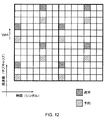
第4の実施形態では、摂動の一種がCRSに適用される。上で議論したように、サブフレームにおけるCRSを有するサブキャリアの垂直シフトは、PCIの関数である。UEは、PCIの周波数オフセットVshift、PCIのモジュロ6部分に従って定義されたリソースにおいて与えられたPCIに基づくCRSが存在することを予期する。これは、図12において説明され、ここで周波数オフセットVshift=2が周波数オフセットVshift=0(薄灰色)とともに(濃灰色で)説明されている。
VC placement information by CRS resource shift In the fourth embodiment, a kind of perturbation is applied to CRS. As discussed above, the vertical shift of the subcarrier with CRS in the subframe is a function of PCI. The UE expects a CRS based on the PCI given in resources defined according to the frequency offset V shift of PCI, the
加えて、CRS自体は、TS 36.211セクション6.10.1.1に提示されるシーケンス生成のための方程式を用いて生成され、方程式は、PCI値、NID cellの関数である値Cinitにより初期化される疑似ランダムシーケンスを用いる。(TS 36.211セクション6.10.1.1における)Cinitについての式が以下に再現される:
Cinit=210・(7・(ns+1)+l+1)・(2・NID cell+1)+2・NID cell+NCP。
In addition, the CRS itself is generated using the equation for sequence generation presented in TS 36.211 section 6.10.1.1, which is a value C that is a function of the PCI value, N ID cell. A pseudo-random sequence that is initialized by init is used. The formula for C init (in TS 36.211 Section 6.10.1.1) are reproduced below:
C init = 2 10 · (7 · (n s +1) + l + 1) · (2 · N ID cell +1) +2 · N ID cell + N CP.
その方程式において用いられるCRSのシーケンス生成についてのおよびCinitについての方程式は、したがって、CSI−RSのシーケンス生成において用いられるのと同じ式である。セルのPCI以外のPCIの使用は、標準の関連するセクションにおいて規定されたCinitとは異なるCinitを用いて初期化されるシーケンス生成についての方程式をもたらすであろう。上のCinitについての式において、NID cellは、両方の出現において、予約されたPCI値、nID reservedにより置き換えられる。 The equations for CRS sequence generation and C init used in that equation are therefore the same equations used in CSI-RS sequence generation. Use of a PCI other than the PCI of the cell will result in an equation for sequence generation that is initialized with a C init that is different from the C init specified in the relevant section of the standard. In the formula for C init above, N ID cell is replaced by the reserved PCI value, n ID reserved , in both occurrences.
504のPCIについて、84は各νshiftを共有し、各PCIは、ちょうど1つの定義されたνshiftを有する。この実施形態では、セルにより送信される従来のCRSに加え、予約されたPCI値から生成されるシーケンスを含むさらなるCRSが、当該CRSがリソースに適合しない所定のリソースにおいて送信されるように、(予約されたPCI区分modulo 6に由来する)予期されるシフトと異なるνshiftで送信され、ここでCRSは、現在の仕様(「シフトした」または「予期されない」リソース)に従い予期されるであろう。したがって、図12における濃灰色の陰影がつけられたリソースエレメントは、その内容を生成するための予約されたPCI値の使用および異なるPCI値を再度表示し得る周波数シフトリソース配置を組み合わせたリソースエレメントを現し得、一方で薄灰色の陰影がつけられたリソースエレメントは、「通常の」従来のCRSを現し得る。この実施形態では、このような予期されないまたは不適合のリソースエレメントが、仮想キャリアに関するセルの動作についての情報、例えばVC配置の存在を含む、以前に列挙したこれらの静特性など、を暗示するのに用いられる。 For 504 PCIs, 84 shares each ν shift , and each PCI has exactly one defined ν shift . In this embodiment, in addition to the conventional CRS transmitted by the cell, an additional CRS including a sequence generated from the reserved PCI value is transmitted in a predetermined resource where the CRS does not match the resource ( Sent with a ν shift different from the expected shift (derived from the reserved PCI partition modulo 6), where the CRS would be expected according to the current specification (“shifted” or “unexpected” resource) . Thus, the dark gray shaded resource elements in FIG. 12 are resource elements that combine the use of reserved PCI values to generate their contents and a frequency shift resource arrangement that can again display different PCI values. A resource element that is shaded in light gray may represent a “normal” conventional CRS. In this embodiment, such unexpected or non-conforming resource elements may imply information about the cell's behavior with respect to the virtual carrier, such as their previously listed static characteristics, including the presence of VC placement. Used.
PCI値およびリソース配置の与えられた組み合わせの意義を知るUEは、予約されたPCI値から生成されるシーケンスを用いてこのような「予期されない」CRSについての所定のリソースを検索し、ひとつを発見するとそれを適宜解釈し、関連する配置を得るか、または例えば組み合わせがVCサポートを示さない場合には初期手順を破棄する。 A UE that knows the significance of a given combination of PCI values and resource placement searches a given resource for such an “unexpected” CRS using a sequence generated from the reserved PCI values and finds one Then interpret it accordingly and get the relevant arrangement, or discard the initial procedure if, for example, the combination does not show VC support.
この実施形態は、これらの予約されたPCIが上述したケイパビリティ表示技術の意義を知らないUEの期待によれば「間違い」と特徴づけられ得るであろうリソース中においてのみ存在するであろうから、以前の実施形態よりも少ないセルID企画を必要とする。このような場合におけるUEの応答は、特異的な実行であろう。PCIの組み合わせに対するこのような不適合なCRSリソースは、技術を知らないUEにより決して実際には検出されないことができる。なぜなら、UEは、それが送信されるリソースにおけるこのようなものについて復号を試みないかもしれないし、ともあれ適正なリソースにおけるPCIを有するCRSについてのみ検索しそうであるからである。 This embodiment would only exist in resources where these reserved PCIs could be characterized as "false" according to the UE's expectation that does not know the significance of the capability indication technology described above. Requires less cell ID planning than previous embodiments. The UE response in such a case would be a specific execution. Such incompatible CRS resources for PCI combinations can never be actually detected by UEs that do not know the technology. This is because the UE may not attempt to decode for such in the resource it is transmitted, and is likely to search only for CRS with PCI in the proper resource anyway.
この実施形態の変形では、仕様は、予約されたPCIに従うCRSが送信されることのできる多くの(現仕様において5つまでの)可能性のある「シフトした」リソースを定義することができ、UEが検出する結合した組み合わせは、VCの配置を暗示する。これはUEについてのより高いブラインドサーチ負荷を有するが、システムにおいてより大きな柔軟性を創造するであろう。 In a variation of this embodiment, the specification can define many (up to 5 in the current specification) possible “shifted” resources to which a CRS according to the reserved PCI can be sent, The combined combination detected by the UE implies the placement of the VC. This has a higher blind search load for the UE, but will create greater flexibility in the system.
本開示の目的のために、LTE標準がCRSについての「サブフレーム配置」を定義しないことが、留意される。しかしながら、CRSは、CRSが「サブフレーム毎」に存在する点で、「サブフレーム配置」の形式を暗示しない。 It is noted that for purposes of this disclosure, the LTE standard does not define a “subframe arrangement” for CRS. However, CRS does not imply a form of “subframe arrangement” in that CRS exists “every subframe”.
さらにこの実施形態にかかる送信される追加のCRSは、サブフレーム毎に、またはリソースブロック毎に送信される必要がない。この場合において、これらが送信されるサブフレームおよびリソースブロックは、(仕様中にまたは製造、初期設定において提供され得る)予め定義された情報に含まれる必要があるであろう。この「CRSサブフレーム配置」は、第1〜第3の実施形態の内容において記載されたCSI−RSと同様の様式に従うかもしれない。 Furthermore, the additional CRS transmitted according to this embodiment does not need to be transmitted every subframe or every resource block. In this case, the subframes and resource blocks in which they are transmitted will need to be included in predefined information (which may be provided in the specification or in manufacturing, initial setup). This “CRS subframe arrangement” may follow the same manner as the CSI-RS described in the contents of the first to third embodiments.
セルの送信構成に関する内容を暗示するために不適合なPCI〜CRSリソースマッピングを使用することは、CRSの内容を使用する異例の方法である。 Using non-conforming PCI to CRS resource mapping to imply content related to the cell's transmission configuration is an unusual way of using CRS content.
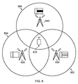
図6は、3つのeNodeB620、630、640のそれぞれのセル602、604、606内の典型的なVC−UE610を示す。eNodeB620は、従来のLTEを提供するが、VC機能を提供しないことができる。eNodeB640は、従来のLTEおよびVC機能を提供するが、現在、高いトラフィック状況を受けており、過負荷を回避することを望む。eNodeB630は、従来のLTEおよびVC機能を提供する
FIG. 6 shows an exemplary VC-
eNodeB620の場合において、実施形態のいずれか1つが、VC機能の欠如がセル獲得の間に利用可能なリファレンスシンボル信号から暗示されることができることを保証するであろう。同様に、eNodeB640は、異なる状況下で従来のLTEおよびVC機能を提供し得る一方で、セル獲得を開始する前にeNodeB640からリファレンスシンボルをバッファリングしている任意のUEがVC機能が現在このeNodeBから利用可能でないことを推測することができるように、利用可能なリファレンスシンボル信号は動的に摂動され得る。
In the case of
これらの「摂動」技術を実装することにより、必要とするVC機能にアクセスすることを試みて失敗するVC−UEにより費やされる時間および処理労力が、従来配置されたワイヤレス通信システムと比較して低減される。 By implementing these “perturbation” techniques, the time and processing effort spent by VC-UEs that attempt to access the required VC functions and fail are reduced compared to previously deployed wireless communication systems. Is done.
これまで記載した実施形態は、仮想キャリアケイパビリティ(静的または動的であろうと)の表示に関する。VCケイパビリティは、しかしながら、記載された「摂動」技術が適用され得る唯一の通信パラメータではない。実際には、上述のケイパビリティ表示技術は、例えばセルがネットワーク共有を運用しているかなど、このような表示がセル獲得前の段階にて有利である任意の通信パラメータの表示に等しく適用され得る。 The embodiments described so far relate to the display of virtual carrier capabilities (whether static or dynamic). VC capability, however, is not the only communication parameter to which the described “perturbation” technique can be applied. In practice, the capability display technique described above can be equally applied to the display of any communication parameter where such a display is advantageous at a stage prior to cell acquisition, for example, whether the cell is operating network sharing.
種々の修正が、添付の請求の範囲において定義されるように、本開示の範囲から出発することなく上記の実施形態に対し行われ得ることが理解されるであろう。特に、実施形態は、LTEモバイル無線ネットワークに関して記載されたけれども、本開示がGSM、3G/UMTS、CDMA2000、WiMAXなどの他のワイヤレス通信システムに適用し得ることが理解されるであろう。 It will be understood that various modifications may be made to the embodiments described above without departing from the scope of the present disclosure, as defined in the appended claims. In particular, although embodiments have been described with reference to LTE mobile radio networks, it will be appreciated that the present disclosure may be applied to other wireless communication systems such as GSM, 3G / UMTS, CDMA2000, WiMAX.
実施形態において予約され得るPCIの例は:
・偶数のPCI(0、2、4、...)
・奇数のPCI(1、3、5、...)
・定義された範囲にわたる連続したPCI値
・特段関係ないくらかの固有値
を含む。
Examples of PCI that can be reserved in an embodiment are:
Even PCI (0, 2, 4, ...)
• Odd PCI (1, 3, 5, ...)
• Consecutive PCI values over a defined range, including some eigenvalues that are not particularly relevant.
3GPP LTE標準のリリース10では、UEは最大で1つのCSI−RS配置を有することができる:リリース11は、この要件を緩和し、任意の数の配置を許容する。通常目的のCSI−RS配置は、通常の方法、すなわちRRCシグナリングにより送られることができるため、上記の技術は、この事実を妨げないことが留意される。
In
UEは、どの実施形態であってもどれが動作中であるかを見つけるために、CSI−RS配置の中から予約された可能性についての初期の獲得プロセスの間に、個別に検索する必要があるであろう。RRC構成CSI−RS配置は、独立して後に送信され得、最初の3つの実施形態において使用される予約されたCSI−RS配置と同一または異なり得る。 The UE needs to search individually during the initial acquisition process for the possibility of being reserved from within the CSI-RS deployment to find out which is working in any embodiment Will. The RRC configuration CSI-RS configuration may be transmitted later independently and may be the same or different from the reserved CSI-RS configuration used in the first three embodiments.
さらに、CRSおよびCSI−RSに関する上記の実施形態は、添付の請求の範囲において定義されるように、本開示の範囲から出発することなく独立してまたは組み合わせて使用されることができる。必ずしも同一の型でないRSの2つのセットが、共存することができる。具体的には、本開示は、また、「通常の」従来のCSI−RSが全く構成されていないかもしれない第2の実施形態を第4と組み合わせる状況を包含する:ネットワークは、予約されたCSI−RS配置のみを、および第4の実施形態において記載されるCRSと並行して予約されたCSI−RS配置を、送信し得る。 Moreover, the above embodiments for CRS and CSI-RS can be used independently or in combination without departing from the scope of the present disclosure, as defined in the appended claims. Two sets of RSs that are not necessarily of the same type can coexist. In particular, the present disclosure also encompasses the situation where the “normal” conventional CSI-RS may not be configured at all to combine the second embodiment with the fourth: the network is reserved Only the CSI-RS arrangement may be transmitted, and the CSI-RS arrangement reserved in parallel with the CRS described in the fourth embodiment.
上のそれぞれの実施形態において議論されたPCIの予約、CSI−RS配置および不適合なCRSリソースは、UEがセルへのRRC接続を得る前にこのような表示を検索するように構成され得るように、および初期セル手順をできる限り早期に妨害する、および適切であれば、破棄するために、事前に特定されていてもよい。あるいは、本開示は、ネットワークオペレータおよび端末製造業者の間の合意により準拠したUEに実装され得る。 The PCI reservation, CSI-RS placement and non-conforming CRS resources discussed in each of the above embodiments may be configured to retrieve such indications before the UE obtains an RRC connection to the cell. And may be specified in advance to disrupt early cell procedures as early as possible and, if appropriate, to be discarded. Alternatively, the present disclosure may be implemented in a compliant UE with an agreement between the network operator and the terminal manufacturer.
ここで使用される用語MTC端末は、ユーザ機器(UE)、モバイル通信デバイス、端末デバイスなどと置き換えることができる。さらに、用語基地局は、UEにセル方式電気通信ネットワークへの無線インターフェースを提供する任意のワイヤレスネットワークエンティティをいい:本用語は前述においてe−NodeBと置き換え可能に用いられてきた一方で、それはLTEおよびeNode−Bs;Node−Bs、ピコ−、フェムト−およびマイクロ−基地局の設備、中継装置;リピーターを含む代わりの無線アクセスアーキテクチャにおける等価のネットワークエンティティを包含する。 The term MTC terminal used herein may be replaced with user equipment (UE), mobile communication device, terminal device, and the like. In addition, the term base station refers to any wireless network entity that provides a UE with a radio interface to a cellular telecommunication network: while this term has been used interchangeably with e-NodeB in the foregoing, it refers to LTE. And eNode-Bs; Node-Bs, pico-, femto- and micro-base station equipment, relay equipment; including equivalent network entities in alternative radio access architectures including repeaters.
読者は、様々な例示的な実施形態が、一般的に相互に排他的ではなく、各々の特徴は適切な場合に置き換えられおよび組み合わせられ得ることを理解するであろう。 The reader will understand that the various exemplary embodiments are generally not mutually exclusive, and each feature may be replaced and combined where appropriate.
付属文書1:仮想キャリア
仮想キャリア概念は、多数の同時係属特許出願(英国特許出願1101970.0[2]、英国特許出願1101981.7[3]、英国特許出願1101966.8[4]、英国特許出願1101983.3[5]、英国特許出願1101853.8[6]、英国特許出願1101982.5[7]、英国特許出願1101980.9[8]および英国特許出願1101972.6[9]を含む)において記載されている。仮想キャリアの概念のある側面が以下に提示される。このセクションにおいて、以下の略語が頻繁に採用される:仮想キャリア−VC、ホストキャリア‐HC、ユーザ機器−UE、リソースブロック−RB、無線周波数−RF、およびベースバンド−BB。
Annex 1: Virtual Carrier The virtual carrier concept is based on numerous co-pending patent applications (UK patent application 1101970.0 [2], UK patent application 11019811.7 [3], UK patent application 1101966.8 [4], UK patent). Application 1101103.3 [5], UK patent application 1101853.8 [6], UK patent application 1101982.5 [7], UK patent application 1101980.9 [8] and UK patent application 1101972.6 [9]) It is described in. Some aspects of the concept of virtual carrier are presented below. In this section, the following abbreviations are frequently employed: virtual carrier-VC, host carrier-HC, user equipment-UE, resource block-RB, radio frequency-RF, and baseband-BB.
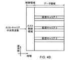
従来のOFDMのように、仮想キャリア概念は、中央周波数から所定のオフセットで配置された複数のサブキャリアを有する:したがって、中央周波数は、仮想キャリア全体を特徴づける。
典型的な仮想キャリア帯域幅は、LTEにおける最小の3GPP帯域幅と一致する6つのリソースブロック(すなわち72のサブキャリア)である。しかしながら、以下の記載にみられるように、VCの帯域幅は、決して6RBに制限されない。
Like conventional OFDM, the virtual carrier concept has multiple subcarriers arranged at a predetermined offset from the central frequency: the central frequency thus characterizes the entire virtual carrier.
A typical virtual carrier bandwidth is 6 resource blocks (ie 72 subcarriers) that match the smallest 3GPP bandwidth in LTE. However, as will be seen in the following description, the VC bandwidth is never limited to 6 RBs.
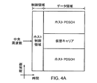
LTEについての3GPP標準のリリース8(REL8 LTE)と合致して、VCリソースは、典型的にホストキャリア中央周波数の中央のリソースブロックに配置され、システムの帯域幅に関わりなく(そのHC中央周波数の両側において)対称に割り当てられている。
Consistent with
図4は、ホストキャリア中央周波数上の中央のリソースブロックを占める仮想キャリア401を有するダウンリンクLTEサブフレームの構造を説明するグリッドの概略図である。仮想キャリア中央周波数403は、ホストキャリアの中央周波数401となるように選択される。 FIG. 4 is a schematic diagram of a grid illustrating the structure of a downlink LTE subframe with a virtual carrier 401 occupying a central resource block on the host carrier central frequency. The virtual carrier center frequency 403 is selected to be the host carrier center frequency 401.
図3において説明される従来のLTEダウンリンクサブフレームを順守して、最初のnシンボルは、PDCCH、PCFICHまたはPHICH上で送信されるデータなどのダウンリンク制御データの送信のために予約された制御領域300を形成する。
In compliance with the conventional LTE downlink subframe described in FIG. 3, the first n symbols are reserved for transmission of downlink control data such as data transmitted on PDCCH, PCFICH or PHICH.
仮想キャリア401の信号は、ホストキャリア上で動作する端末デバイスが適正に動作するために必要とし、既知の所定の位置(例えば、図3の中央帯310におけるPSS、SSSおよびPBCH)において見出すことを期待するホストキャリアによって送信される信号が維持されるように、準備される。仮想キャリアは、このようなホストキャリアリソース内にあり、しかしホストキャリアリソースから論理的に区別可能なリソースを使用するように構成されている。
The virtual carrier 401 signal is required for the terminal device operating on the host carrier to operate properly and is to be found at a known predetermined location (eg, PSS, SSS and PBCH in the
図4からわかるように、仮想キャリア401上で送信されるデータは、制限された帯域幅にわたって送信される。これは、ホストキャリアのそれよりも小さい任意の適切な帯域幅であり得る。図4に示される例において、仮想キャリアは、2.16MHz送信帯域幅と同等である12のサブキャリアの12のブロック(すなわち144サブキャリア)を含む帯域幅にわたって送信される。したがって、仮想キャリア401を用いる端末は、2.16MHzの帯域幅にわたって送信されるデータを受信し、処理することのできる受信機を備えることのみ必要である。これは、低ケイパビリティ端末(例えばMTC型端末)に、それでも、上で説明したように、信号の帯域幅全体にわたったOFDM信号を受信し、処理することのできる受信機を備える端末を従来必要とするOFDM型通信ネットワーク内で動作可能であるけれども、単純化された受信機ユニットが提供されることを可能とする。 As can be seen from FIG. 4, data transmitted on the virtual carrier 401 is transmitted over a limited bandwidth. This can be any suitable bandwidth smaller than that of the host carrier. In the example shown in FIG. 4, the virtual carrier is transmitted over a bandwidth that includes 12 blocks of 12 subcarriers (ie, 144 subcarriers) that are equivalent to the 2.16 MHz transmission bandwidth. Thus, a terminal using virtual carrier 401 need only have a receiver that can receive and process data transmitted over a 2.16 MHz bandwidth. This requires a terminal with a low capability terminal (eg, an MTC type terminal) that still has a receiver that can receive and process OFDM signals over the entire signal bandwidth, as described above. A simplified receiver unit can be provided, although it can operate in an OFDM type communication network.
従来のLTE端末がセル中でデータを送信し、受信することを開始することができる前に、それはまずセル内へキャンプオンする。同様に、適合するキャンプオンプロセスが、仮想キャリアを用いた端末について提供される。仮想キャリアのための適切なキャンプオンプロセスは、英国特許出願1113801.3[10]において詳細に記載されている:このキャンプオンプロセスは参照によりここに組み込まれる。 Before a conventional LTE terminal can start sending and receiving data in a cell, it first camps into the cell. Similarly, a compatible camp-on process is provided for terminals using virtual carriers. A suitable camp-on process for virtual carriers is described in detail in UK patent application 1113801.3 [10]: this camp-on process is incorporated herein by reference.
英国特許出願1113801.3[10]に記載されるように、「従来のLTE」および仮想キャリアの実行の両方は、好都合なことに、ホストキャリア中央帯におけるマスタ情報ブロック(MIB)をすでに持つPBCH内に仮想キャリアのための位置情報を含み得る。あるいは、仮想キャリア位置情報は、PBCHの外部であるけれども中央帯に提供され得る。例えば、それは、常にPBCHの後にかつ隣接して提供され得る。PBCHの外部であるが中央帯における位置情報を提供することにより、従来のPBCHは仮想キャリアを用いる目的について変更されないが、この場合でも仮想キャリア端末は、仮想キャリアを検出するために位置情報を容易に発見することができる。 As described in UK patent application 1113801.3 [10], both “traditional LTE” and virtual carrier implementations advantageously have a PBCH already having a master information block (MIB) in the host carrier central zone. May contain location information for the virtual carrier. Alternatively, the virtual carrier location information can be provided outside the PBCH but in the central band. For example, it can always be provided after and adjacent to the PBCH. By providing location information outside the PBCH but in the central band, the conventional PBCH remains unchanged for the purpose of using the virtual carrier, but even in this case, the virtual carrier terminal can easily provide location information to detect the virtual carrier. Can be found in.
仮想キャリア位置情報は、提供される場合、ホストキャリアにおける他のどこかで提供される一方で、例えば、仮想キャリア端末はその受信機が中央帯において動作するように構成し得、仮想キャリア端末は次いで位置情報を発見するためのその受信機設定を調整する必要がないため、中央帯においてそれを提供することは有利である。 For example, if provided, the virtual carrier location information is provided elsewhere on the host carrier, while the virtual carrier terminal may be configured such that its receiver operates in the central band, and the virtual carrier terminal is It is then advantageous to provide it in the central band, since it is not necessary to adjust its receiver settings for finding location information.
提供された仮想キャリア位置情報の量に応じて、仮想キャリア端末は、その受信機が仮想キャリア送信信号を受信するか、それがそのようにし得る前にさらなる位置情報を要求し得るように調整することができる。 Depending on the amount of virtual carrier location information provided, the virtual carrier terminal adjusts so that its receiver can receive the virtual carrier transmission signal or request further location information before it can do so. be able to.
例えば、仮想キャリア端末に正確な仮想キャリア周波数範囲に関しなんら詳細を示さない仮想キャリアの存在および/または仮想キャリア帯域幅が提供された場合、または仮想キャリア端末に任意の位置情報が提供されなかった場合、仮想キャリア端末はその後仮想キャリアについてホストキャリアをスキャンし得る(例えば、いわゆるブラインドサーチプロセスを行う)。このプロセスもまた、英国特許出願1113801.3[10]において詳細に議論されている。 For example, when virtual carrier presence and / or virtual carrier bandwidth is provided that does not show any details about the exact virtual carrier frequency range to the virtual carrier terminal, or when any location information is not provided to the virtual carrier terminal The virtual carrier terminal can then scan the host carrier for a virtual carrier (eg, performing a so-called blind search process). This process is also discussed in detail in UK patent application 1113801.3 [10].
読者は、仮想チャンネルの複数の過程が同一のセル内における異なる周波数帯において実行され得ることを容易に理解するであろう。図5は、3つの異なる仮想チャネルを示すダウンリンクLTEサブフレームの概略図を示す。 The reader will readily understand that multiple processes of virtual channels can be performed in different frequency bands within the same cell. FIG. 5 shows a schematic diagram of a downlink LTE subframe showing three different virtual channels.
以下の番号付された項目は、本技術の側面および特徴例をさらに提供する: The following numbered items further provide example aspects and features of the technology:
1. ワイヤレス通信システムに関連付られた通信パラメータの表示を導出するためのモバイル端末であって、前記ワイヤレス通信システムは:
1以上の基地局を有し、これらの各々は、端末へデータを通信するためのワイヤレスアクセスインターフェースを提供するように構成された送信機を含み、
前記ワイヤレスアクセスインターフェースは、複数の通信リソースエレメントを提供し、
前記通信リソースエレメントは、複数の時分割無線フレームに纏められており、
各無線フレーム中の前記リソースエレメントの第1のサブセットは、少なくとも1つの同期信号を搬送し、基地局についての前記同期信号は第1の識別番号と関連付られており、および、
各無線フレーム中の前記リソースエレメントの第2のサブセットは、リファレンスシンボルを有するリファレンス信号を搬送し、前記第2のサブセットは、第1の配置および第2の配置を含む複数の離散配置に分割されており、前記第1の配置中の前記リファレンスシンボルは、前記第1の識別番号に従って変化する少なくとも1つのプロパティを有し、
前記モバイル端末は:
前記ワイヤレスアクセスインターフェースの前記通信リソースエレメントの少なくともいくらかを受信する受信機、および
前記受信した通信リソースエレメントの少なくともいくらかを処理するためのプロセッサを有し;ここで、動作中、前記プロセッサは、前記受信した通信リソースエレメントにおいて存在する前記リファレンスシンボルの少なくとも1つのプロパティの値を決定し;前記通信パラメータの値は、前記第2の配置における前記リファレンスシンボルの少なくとも1つのプロパティから推定される、前記モバイル端末。
1. A mobile terminal for deriving an indication of communication parameters associated with a wireless communication system, the wireless communication system comprising:
One or more base stations, each of which includes a transmitter configured to provide a wireless access interface for communicating data to the terminal;
The wireless access interface provides a plurality of communication resource elements;
The communication resource elements are grouped into a plurality of time division radio frames,
A first subset of the resource elements in each radio frame carries at least one synchronization signal, the synchronization signal for a base station being associated with a first identification number; and
A second subset of the resource elements in each radio frame carries a reference signal having a reference symbol, and the second subset is divided into a plurality of discrete arrangements including a first arrangement and a second arrangement. The reference symbol in the first arrangement has at least one property that varies according to the first identification number;
The mobile terminal is:
A receiver that receives at least some of the communication resource elements of the wireless access interface; and a processor for processing at least some of the received communication resource elements; wherein, in operation, the processor receives the reception Determining a value of at least one property of the reference symbol present in the communication resource element, wherein the value of the communication parameter is estimated from at least one property of the reference symbol in the second arrangement .
2. 推定された前記通信パラメータは、前記基地局より提供される前記ワイヤレスアクセスインターフェースの静特性である、項目1に記載のモバイル端末。
2. The mobile terminal according to
3. 前記静特性は、狭帯域キャリアを提供するための前記基地局のケイパビリティであり、前記狭帯域キャリアは、前記無線フレームの前記リソースエレメントの第3のサブセットを占有し、前記ワイヤレスアクセスインターフェースによって供給された帯域幅よりも狭い帯域幅を有する、項目2に記載のモバイル端末。
3. The static characteristic is a capability of the base station to provide a narrowband carrier, the narrowband carrier occupying a third subset of the resource elements of the radio frame and provided by the wireless access interface.
4. 前記リファレンスシンボルの少なくとも1つのプロパティは、それぞれの受信したリファレンスシンボルが属するリファレンス信号配置であり、および前記通信パラメータの前記値は、前記第2の配置におけるリファレンスシンボルの存在から推定される、項目1〜3に記載のモバイル端末。
4).
5. 前記通信パラメータの前記値は、前記第2の配置および前記第1の配置の間の差異から推定される、項目4に記載のモバイル端末。
5. The mobile terminal according to
6. 前記第2の配置は、複数の離散配置の予め定められた1つである、項目4または5に記載のモバイル端末。
6). The mobile terminal according to
7. 前記第2の配置は、通信パラメータの値の表示における使用のために予約されている、項目6に記載のモバイル端末。
7).
8. 前記リファレンスシンボルの少なくとも1つのプロパティは、リファレンス信号シーケンスであり、前記プロセッサにより決定される少なくとも1つの前記リファレンスシンボルの値は、前記リファレンス信号シーケンスに対応する値を含み、および、前記通信パラメータの値の推定は、前記第2の配置における前記リファレンス信号シーケンスに依存する、項目1〜7に記載のモバイル端末。
8). At least one property of the reference symbol is a reference signal sequence, a value of the at least one reference symbol determined by the processor includes a value corresponding to the reference signal sequence, and a value of the
9. 前記リファレンス信号シーケンスは、前記第1の識別番号とは異なる第2の識別番号に従って変化し、および
前記通信パラメータの前記値は、前記第2の配置において使用される前記第2の識別番号の値から推定される、項目8に記載のモバイル端末。
9. The reference signal sequence varies according to a second identification number different from the first identification number, and the value of the communication parameter is a value of the second identification number used in the
10. 前記通信パラメータの前記値は、前記第2の識別番号および前記第1の配置において使用される前記第1の識別番号の間の差異から推定される、項目9に記載のモバイル端末。
10. The mobile terminal according to
11. 前記第2の配置における前記リファレンス信号シーケンスは、前記第2の識別番号の関数として生成される、項目9または10に記載のモバイル端末。
11. 11. The mobile terminal according to
12. 前記リファレンス信号の少なくとも1つのプロパティは、リファレンス信号サブフレーム配置であり、および前記プロセッサにより決定される前記リファレンスシンボルプロパティの少なくとも1つの値は、前記リファレンス信号サブフレーム配置に対応する値であり、および
前記通信パラメータの前記値が推定される前記第2の配置における前記リファレンスシンボルの前記プロパティは、前記第1の配置が属する前記サブフレーム配置とは異なるサブフレーム配置におけるリファレンスシンボルの存在である、項目1〜11に記載のモバイル端末。
12 At least one property of the reference signal is a reference signal subframe arrangement, and at least one value of the reference symbol property determined by the processor is a value corresponding to the reference signal subframe arrangement; and The property of the reference symbol in the second arrangement where the value of the communication parameter is estimated is the presence of a reference symbol in a subframe arrangement different from the subframe arrangement to which the first arrangement belongs The mobile terminal according to 1 to 11.
13. 前記リファレンスシンボルの少なくとも1つのプロパティは:
リファレンス信号サブフレーム配置;
リファレンス信号配置;および
リファレンス信号シーケンス;
の少なくとも2つの組み合わせであり、前記通信パラメータは、前記第2の配置における前記リファレンスシンボルのプロパティの前記組み合わせから推定される、項目1〜12に記載のモバイル端末。
13. At least one property of the reference symbol is:
Reference signal subframe arrangement;
Reference signal arrangement; and reference signal sequence;
13. The mobile terminal according to
14. 前記第1の識別番号に従って変化する前記第1の配置における前記リファレンスシンボルの少なくとも1つのプロパティは、前記リファレンス信号シーケンスであり、前記第1の配置は、前記第1の識別番号の関数として生成される第1のリファレンス信号シーケンスにおけるリファレンス信号を有し、および
前記第2の配置は、前記第1のリファレンス信号シーケンスと異なる第2のリファレンス信号シーケンスにおけるリファレンス信号を有し、前記第2のリファレンス信号シーケンスは前記第2の識別番号を用いて生成され、前記第2の識別番号は、予約された識別番号に対応する、任意の前述の項目に記載のモバイル端末。
14 At least one property of the reference symbol in the first arrangement that varies according to the first identification number is the reference signal sequence, and the first arrangement is generated as a function of the first identification number. A reference signal in a first reference signal sequence, and the second arrangement has a reference signal in a second reference signal sequence different from the first reference signal sequence, and the second reference signal A mobile terminal according to any preceding item, wherein a sequence is generated using said second identification number, said second identification number corresponding to a reserved identification number.
15. 前記第1のリファレンス信号シーケンスは、前記第1の識別番号をシードとして用いてリファレンス信号アルゴリズムにおいて生成され、および前記第2のリファレンス信号シーケンスは、前記第2の識別番号をシードとして用いてリファレンス信号アルゴリズムにおいて生成される、項目14に記載のモバイル端末。
15. The first reference signal sequence is generated in a reference signal algorithm using the first identification number as a seed, and the second reference signal sequence is a reference signal using the second identification number as a seed. Item 15. The mobile terminal according to
16. 前記第2のサブセットにおける前記リファレンスシンボルは、チャネル状態情報リファレンス信号、CSI−RSを含む、任意の前述の項目に記載のモバイル端末。 16. The mobile terminal of any preceding item, wherein the reference symbols in the second subset include a channel state information reference signal, CSI-RS.
17. 前記第2のサブセットにおける前記リファレンスシンボルは、セル固有リファレンス信号、CRSを含む、任意の前述の項目に記載のモバイル端末。 17. The mobile terminal of any preceding item, wherein the reference symbols in the second subset include a cell specific reference signal, CRS.
18. 前記リファレンス信号の少なくとも1つのプロパティは、それぞれの受信したリファレンスシンボルが属するセル固有リファレンス信号配置であり、前記第2の配置は、第2の識別番号に従い複数の離散配置から選択され、および前記第2の配置における前記リファレンスシンボルは、第2の識別番号を用いて生成され、前記通信パラメータの前記値は、前記第2の配置における前記セル固有リファレンス信号を生成するのに用いられる前記識別番号が前記第1の識別番号とは異なることを判定することにより推定される、項目17に記載のモバイル端末。 18. At least one property of the reference signal is a cell-specific reference signal arrangement to which each received reference symbol belongs, the second arrangement is selected from a plurality of discrete arrangements according to a second identification number, and the first The reference symbol in the second arrangement is generated using a second identification number, and the value of the communication parameter is the identification number used to generate the cell-specific reference signal in the second arrangement. Item 18. The mobile terminal according to Item 17, which is estimated by determining that it is different from the first identification number.
19. 前記第2の識別番号は、通信パラメータの値の表示における使用のために予約された、予め定められた識別番号である、項目18に記載のモバイル端末。 19. Item 19. The mobile terminal of item 18, wherein the second identification number is a predetermined identification number reserved for use in displaying communication parameter values.
20. 端末へデータを通信するためのワイヤレスアクセスインターフェースを提供するように構成されたワイヤレス通信システムにおいて通信パラメータの表示を導出する方法であって、
前記ワイヤレスアクセスインターフェースは、複数の通信リソースエレメントを提供し、
前記通信リソースエレメントは、複数の時分割無線フレームにおいて纏められており、
各無線フレーム中の前記リソースエレメントの第1のサブセットは、少なくとも1つの同期信号を搬送し、基地局についての前記同期信号は第1の識別番号と関連付られており、および
各無線フレーム中の前記リソースエレメントの第2のサブセットは、リファレンスシンボルを搬送し、前記第2のサブセットは、第1の配置および第2の配置を含む複数の離散配置に分割されており、前記第1の配置中の前記リファレンスシンボルは、前記第1の識別番号に従って変化する少なくとも1つのプロパティを有し、
前記方法は:
前記ワイヤレスアクセスインターフェースの前記通信リソースエレメントの少なくともいくらかを受信すること、
前記受信した通信リソースエレメントの少なくともいくらかを処理して、前記受信した通信リソースエレメントに存在する前記リファレンスシンボルの少なくとも1つのプロパティの値を決定すること、および
前記第2の配置における前記リファレンスシンボルの少なくとも1つのプロパティから前記通信パラメータの値を導出すること、を有する、前記方法。
20. A method for deriving an indication of communication parameters in a wireless communication system configured to provide a wireless access interface for communicating data to a terminal comprising:
The wireless access interface provides a plurality of communication resource elements;
The communication resource elements are grouped in a plurality of time division radio frames,
A first subset of the resource elements in each radio frame carries at least one synchronization signal, the synchronization signal for a base station is associated with a first identification number, and in each radio frame The second subset of resource elements carries reference symbols, and the second subset is divided into a plurality of discrete arrangements including a first arrangement and a second arrangement, during the first arrangement The reference symbol has at least one property that varies according to the first identification number;
The method is:
Receiving at least some of the communication resource elements of the wireless access interface;
Processing at least some of the received communication resource elements to determine a value of at least one property of the reference symbol present in the received communication resource element; and at least of the reference symbols in the second arrangement Deriving the value of the communication parameter from a property.
参考文献
[1]ETSI TS 122 368 V10.530(2011−07)/3GPP TS 22.368 バージョン 10.5.0 リリース10)
[2]英国特許出願1101970.0
[3]英国特許出願1101981.7
[4]英国特許出願1101966.8
[5]英国特許出願1101983.3
[6]英国特許出願1101853.8
[7]英国特許出願1101982.5
[8]英国特許出願1101980.9
[9]英国特許出願1101972.6
[10]英国特許出願1113801.3
Reference [1] ETSI TS 122 368 V10.530 (2011-07) / 3GPP TS 22.368 Version 10.5.0 Release 10)
[2] British patent application 1101970.0
[3] British patent application 11019811.7
[4] British patent application 1101966.8
[5] British patent application 1101983.3
[6] British patent application 1101853.8
[7] British patent application 1101982.5
[8] British patent application 1101980.9
[9] British patent application 1101972.6
[10] British patent application 1113801.3
Claims (20)
1以上の基地局を有し、これらの各々は、端末へデータを通信するためのワイヤレスアクセスインターフェースを提供するように構成された送信機を含み、
前記ワイヤレスアクセスインターフェースは、複数の通信リソースエレメントを提供し、
前記通信リソースエレメントは、複数の時分割無線フレームに纏められており、
各無線フレーム中の前記リソースエレメントの第1のサブセットは、少なくとも1つの同期信号を搬送し、基地局についての前記同期信号は第1の識別番号と関連付られており、および、
各無線フレーム中の前記リソースエレメントの第2のサブセットは、リファレンスシンボルを有するリファレンス信号を搬送し、前記第2のサブセットは、第1の配置および第2の配置を含む複数の離散配置に分割されており、前記第1の配置中の前記リファレンスシンボルは、前記第1の識別番号に従って変化する少なくとも1つのプロパティを有し、
前記モバイル端末は:
前記ワイヤレスアクセスインターフェースの前記通信リソースエレメントの少なくともいくらかを受信する受信機、および
前記受信した通信リソースエレメントの少なくともいくらかを処理するためのプロセッサを有し;ここで、動作中、前記プロセッサは、前記受信した通信リソースエレメントにおいて存在する前記リファレンスシンボルの少なくとも1つのプロパティの値を決定し;前記通信パラメータの値は、前記第2の配置における前記リファレンスシンボルの少なくとも1つのプロパティから推定される、前記モバイル端末。 A mobile terminal for deriving an indication of communication parameters associated with a wireless communication system, the wireless communication system comprising:
One or more base stations, each of which includes a transmitter configured to provide a wireless access interface for communicating data to the terminal;
The wireless access interface provides a plurality of communication resource elements;
The communication resource elements are grouped into a plurality of time division radio frames,
A first subset of the resource elements in each radio frame carries at least one synchronization signal, the synchronization signal for a base station being associated with a first identification number; and
A second subset of the resource elements in each radio frame carries a reference signal having a reference symbol, and the second subset is divided into a plurality of discrete arrangements including a first arrangement and a second arrangement. The reference symbol in the first arrangement has at least one property that varies according to the first identification number;
The mobile terminal is:
A receiver that receives at least some of the communication resource elements of the wireless access interface; and a processor for processing at least some of the received communication resource elements; wherein, in operation, the processor receives the reception Determining a value of at least one property of the reference symbol present in the communication resource element, wherein the value of the communication parameter is estimated from at least one property of the reference symbol in the second arrangement .
前記通信パラメータの前記値は、前記第2の配置において使用される前記第2の識別番号の値から推定される、請求項8に記載のモバイル端末。 The reference signal sequence varies according to a second identification number different from the first identification number, and the value of the communication parameter is a value of the second identification number used in the second arrangement The mobile terminal according to claim 8, estimated from:
前記通信パラメータの前記値が推定される前記第2の配置における前記リファレンスシンボルの前記プロパティは、前記第1の配置が属する前記サブフレーム配置とは異なるサブフレーム配置におけるリファレンスシンボルの存在である、請求項1に記載のモバイル端末。 At least one property of the reference signal is a reference signal subframe arrangement, and at least one value of the reference symbol property determined by the processor is a value corresponding to the reference signal subframe arrangement; and The property of the reference symbol in the second arrangement where the value of the communication parameter is estimated is the presence of a reference symbol in a subframe arrangement different from the subframe arrangement to which the first arrangement belongs. Item 2. The mobile terminal according to Item 1.
リファレンス信号サブフレーム配置;
リファレンス信号配置;および
リファレンス信号シーケンス;
の少なくとも2つの組み合わせであり、前記通信パラメータは、前記第2の配置における前記リファレンスシンボルのプロパティの前記組み合わせから推定される、請求項1に記載のモバイル端末。 At least one property of the reference symbol is:
Reference signal subframe arrangement;
Reference signal arrangement; and reference signal sequence;
The mobile terminal according to claim 1, wherein the communication parameter is estimated from the combination of properties of the reference symbol in the second arrangement.
前記第2の配置は、前記第1のリファレンス信号シーケンスと異なる第2のリファレンス信号シーケンスにおけるリファレンス信号を有し、前記第2のリファレンス信号シーケンスは前記第2の識別番号を用いて生成され、前記第2の識別番号は、予約された識別番号に対応する、請求項1に記載のモバイル端末。 At least one property of the reference symbol in the first arrangement that varies according to the first identification number is the reference signal sequence, and the first arrangement is generated as a function of the first identification number. A reference signal in a first reference signal sequence, and the second arrangement has a reference signal in a second reference signal sequence different from the first reference signal sequence, and the second reference signal The mobile terminal according to claim 1, wherein a sequence is generated using the second identification number, wherein the second identification number corresponds to a reserved identification number.
前記ワイヤレスアクセスインターフェースは、複数の通信リソースエレメントを提供し、
前記通信リソースエレメントは、複数の時分割無線フレームにおいて纏められており、
各無線フレーム中の前記リソースエレメントの第1のサブセットは、少なくとも1つの同期信号を搬送し、基地局についての前記同期信号は第1の識別番号と関連付られており、および
各無線フレーム中の前記リソースエレメントの第2のサブセットは、リファレンスシンボルを搬送し、前記第2のサブセットは、第1の配置および第2の配置を含む複数の離散配置に分割されており、前記第1の配置中の前記リファレンスシンボルは、前記第1の識別番号に従って変化する少なくとも1つのプロパティを有し、
前記方法は:
前記ワイヤレスアクセスインターフェースの前記通信リソースエレメントの少なくともいくらかを受信すること、
前記受信した通信リソースエレメントの少なくともいくらかを処理して、前記受信した通信リソースエレメントに存在する前記リファレンスシンボルの少なくとも1つのプロパティの値を決定すること、および
前記第2の配置における前記リファレンスシンボルの少なくとも1つのプロパティから前記通信パラメータの値を導出すること、を有する、前記方法。
A method for deriving an indication of communication parameters in a wireless communication system configured to provide a wireless access interface for communicating data to a terminal comprising:
The wireless access interface provides a plurality of communication resource elements;
The communication resource elements are grouped in a plurality of time division radio frames,
A first subset of the resource elements in each radio frame carries at least one synchronization signal, the synchronization signal for a base station is associated with a first identification number, and in each radio frame The second subset of resource elements carries reference symbols, and the second subset is divided into a plurality of discrete arrangements including a first arrangement and a second arrangement, during the first arrangement The reference symbol has at least one property that varies according to the first identification number;
The method is:
Receiving at least some of the communication resource elements of the wireless access interface;
Processing at least some of the received communication resource elements to determine a value of at least one property of the reference symbol present in the received communication resource element; and at least of the reference symbols in the second arrangement Deriving the value of the communication parameter from a property.
Applications Claiming Priority (3)
| Application Number | Priority Date | Filing Date | Title |
|---|---|---|---|
| GB1223313.6A GB2509161B (en) | 2012-12-21 | 2012-12-21 | Telecommunications apparatus and method |
| GB1223313.6 | 2012-12-21 | ||
| PCT/GB2013/053125 WO2014096769A1 (en) | 2012-12-21 | 2013-11-26 | Deriving an indication of a communications parameter using reference symbols |
Publications (2)
| Publication Number | Publication Date |
|---|---|
| JP2016508317A true JP2016508317A (en) | 2016-03-17 |
| JP6309023B2 JP6309023B2 (en) | 2018-04-11 |
Family
ID=47682524
Family Applications (1)
| Application Number | Title | Priority Date | Filing Date |
|---|---|---|---|
| JP2015548745A Active JP6309023B2 (en) | 2012-12-21 | 2013-11-26 | Derivation of communication parameter display using reference symbols |
Country Status (7)
| Country | Link |
|---|---|
| US (1) | US9800997B2 (en) |
| EP (1) | EP2936724B1 (en) |
| JP (1) | JP6309023B2 (en) |
| KR (1) | KR102118765B1 (en) |
| CN (1) | CN104871473B (en) |
| GB (1) | GB2509161B (en) |
| WO (1) | WO2014096769A1 (en) |
Cited By (1)
| Publication number | Priority date | Publication date | Assignee | Title |
|---|---|---|---|---|
| JP2019517208A (en) * | 2016-05-13 | 2019-06-20 | ホアウェイ・テクノロジーズ・カンパニー・リミテッド | Method of transmitting downlink control information, method of detecting downlink control information, and device |
Families Citing this family (16)
| Publication number | Priority date | Publication date | Assignee | Title |
|---|---|---|---|---|
| GB2509162B (en) * | 2012-12-21 | 2018-09-26 | Sony Corp | Telecommunications apparatus and methods |
| US9713075B2 (en) * | 2014-01-10 | 2017-07-18 | Kt Corporation | Method and apparatus for measuring channel for small cell discovery |
| CN106034345B (en) * | 2015-04-17 | 2021-02-09 | 索尼公司 | Terminal side, base station side device, terminal device, base station, and wireless communication method |
| JPWO2017033841A1 (en) * | 2015-08-21 | 2018-06-14 | 株式会社Nttドコモ | User terminal, radio base station, and radio communication method |
| WO2017177419A1 (en) * | 2016-04-14 | 2017-10-19 | 华为技术有限公司 | Information transmission method, device and system |
| US11563505B2 (en) | 2016-06-01 | 2023-01-24 | Qualcomm Incorporated | Time division multiplexing of synchronization channels |
| US11218236B2 (en) | 2016-06-01 | 2022-01-04 | Qualcomm Incorporated | Time division multiplexing of synchronization channels |
| US10887035B2 (en) | 2016-06-01 | 2021-01-05 | Qualcomm Incorporated | Time division multiplexing of synchronization channels |
| US10498437B2 (en) * | 2016-06-01 | 2019-12-03 | Qualcomm Incorporated | Conveying hypotheses through resource selection of synchronization and broadcast channels |
| US10218406B2 (en) * | 2016-09-02 | 2019-02-26 | Qualcomm Incorporated | Narrowband communication for different device capabilities in unlicensed spectrum |
| CN108668355B (en) * | 2017-04-01 | 2021-07-09 | 华为技术有限公司 | A communication method, network side device and terminal |
| RU2746801C1 (en) * | 2017-08-10 | 2021-04-21 | Телефонактиеболагет Лм Эрикссон (Пабл) | Improved control over control channel |
| CN110446258B (en) * | 2018-05-04 | 2022-03-29 | 大唐移动通信设备有限公司 | Position determination method of paging opportunity and communication equipment |
| CN110557239B (en) * | 2019-08-30 | 2022-05-27 | 北京紫光展锐通信技术有限公司 | Method and device for determining CRS (cell-specific reference signal) sequence |
| CN120658361A (en) * | 2022-01-10 | 2025-09-16 | 北京小米移动软件有限公司 | Reference signal availability indication method and device, network element equipment, terminal and storage medium |
| CN119071908A (en) * | 2023-06-02 | 2024-12-03 | 华为技术有限公司 | A communication method and device |
Citations (4)
| Publication number | Priority date | Publication date | Assignee | Title |
|---|---|---|---|---|
| JP2005151573A (en) * | 2003-11-15 | 2005-06-09 | Samsung Electronics Co Ltd | Apparatus and method for transmitting control information in mobile communication system |
| JP2006067262A (en) * | 2004-08-27 | 2006-03-09 | Hitachi Kokusai Electric Inc | Wireless communication system |
| JP2010509837A (en) * | 2006-11-13 | 2010-03-25 | テレフオンアクチーボラゲット エル エム エリクソン(パブル) | Method and apparatus for control signaling based on pilot pattern in MIMO system |
| WO2012104633A1 (en) * | 2011-02-04 | 2012-08-09 | Wireless Technology Solutions Llc | Inserting virtual carrier in conventional ofdm host carrier in communications system |
Family Cites Families (16)
| Publication number | Priority date | Publication date | Assignee | Title |
|---|---|---|---|---|
| JP2008035285A (en) * | 2006-07-28 | 2008-02-14 | Kyocera Corp | Wireless communication apparatus and wireless communication method |
| US8571120B2 (en) * | 2006-09-22 | 2013-10-29 | Texas Instruments Incorporated | Transmission of acknowledge/not acknowledge (ACK/NACK) bits and their embedding in the reference signal |
| US8149938B2 (en) * | 2007-08-07 | 2012-04-03 | Texas Instruments Incorporated | Transmission of ACK/NACK bits and their embedding in the CQI reference signal |
| US8913672B2 (en) * | 2008-09-12 | 2014-12-16 | Qualcomm Incorporated | Efficiently identifying system waveform in uplink transmission |
| US20100232311A1 (en) * | 2009-03-12 | 2010-09-16 | Qualcomm Incorporated | Concurrent transmission of ack/nack, cqi and cqi from user equipment |
| WO2010147445A2 (en) * | 2009-06-19 | 2010-12-23 | 엘지전자 주식회사 | Cell searching method and apparatus in multi-carrier system |
| US9252930B2 (en) * | 2011-01-07 | 2016-02-02 | Futurewei Technologies, Inc. | Reference signal transmission and reception method and equipment |
| GB2487757B (en) | 2011-02-03 | 2015-11-04 | Nvidia Corp | Apparatus and method for reducing interference |
| GB2487909B8 (en) | 2011-02-04 | 2015-01-21 | Sca Ipla Holdings Inc | Telecommunications method and system |
| GB2487907B (en) | 2011-02-04 | 2015-08-26 | Sca Ipla Holdings Inc | Telecommunications method and system |
| GB2488513B (en) | 2011-02-04 | 2015-06-24 | Sca Ipla Holdings Inc | Telecommunication method and systen |
| GB2487906B (en) | 2011-02-04 | 2015-02-25 | Wireless Tech Solutions Llc | Telecommunication method and system |
| GB2487780B (en) | 2011-02-04 | 2015-01-14 | Sca Ipla Holdings Inc | Infrastructure equipment and method |
| GB2487908B (en) | 2011-02-04 | 2015-06-17 | Sca Ipla Holdings Inc | Telecommunications method and system |
| US9485075B2 (en) | 2011-04-29 | 2016-11-01 | Futurewei Technologies Inc. | Method and system for transmission and reception of signals and related method of signaling |
| GB2493703C (en) | 2011-08-11 | 2020-03-04 | Sca Ipla Holdings Inc | OFDM subcarrier allocations in wireless telecommunications systems |
-
2012
- 2012-12-21 GB GB1223313.6A patent/GB2509161B/en not_active Expired - Fee Related
-
2013
- 2013-11-26 US US14/439,479 patent/US9800997B2/en active Active
- 2013-11-26 WO PCT/GB2013/053125 patent/WO2014096769A1/en not_active Ceased
- 2013-11-26 KR KR1020157016154A patent/KR102118765B1/en active Active
- 2013-11-26 JP JP2015548745A patent/JP6309023B2/en active Active
- 2013-11-26 EP EP13799636.9A patent/EP2936724B1/en active Active
- 2013-11-26 CN CN201380067135.3A patent/CN104871473B/en active Active
Patent Citations (4)
| Publication number | Priority date | Publication date | Assignee | Title |
|---|---|---|---|---|
| JP2005151573A (en) * | 2003-11-15 | 2005-06-09 | Samsung Electronics Co Ltd | Apparatus and method for transmitting control information in mobile communication system |
| JP2006067262A (en) * | 2004-08-27 | 2006-03-09 | Hitachi Kokusai Electric Inc | Wireless communication system |
| JP2010509837A (en) * | 2006-11-13 | 2010-03-25 | テレフオンアクチーボラゲット エル エム エリクソン(パブル) | Method and apparatus for control signaling based on pilot pattern in MIMO system |
| WO2012104633A1 (en) * | 2011-02-04 | 2012-08-09 | Wireless Technology Solutions Llc | Inserting virtual carrier in conventional ofdm host carrier in communications system |
Cited By (2)
| Publication number | Priority date | Publication date | Assignee | Title |
|---|---|---|---|---|
| JP2019517208A (en) * | 2016-05-13 | 2019-06-20 | ホアウェイ・テクノロジーズ・カンパニー・リミテッド | Method of transmitting downlink control information, method of detecting downlink control information, and device |
| US10869304B2 (en) | 2016-05-13 | 2020-12-15 | Huawei Technologies Co., Ltd. | Downlink control information sending method, downlink control information detection method, and device |
Also Published As
| Publication number | Publication date |
|---|---|
| CN104871473A (en) | 2015-08-26 |
| KR20150100672A (en) | 2015-09-02 |
| JP6309023B2 (en) | 2018-04-11 |
| KR102118765B1 (en) | 2020-06-03 |
| GB2509161A (en) | 2014-06-25 |
| GB201223313D0 (en) | 2013-02-06 |
| GB2509161B (en) | 2018-09-26 |
| WO2014096769A1 (en) | 2014-06-26 |
| US9800997B2 (en) | 2017-10-24 |
| EP2936724A1 (en) | 2015-10-28 |
| EP2936724B1 (en) | 2018-08-08 |
| CN104871473B (en) | 2018-04-20 |
| US20150289079A1 (en) | 2015-10-08 |
Similar Documents
| Publication | Publication Date | Title |
|---|---|---|
| JP6309023B2 (en) | Derivation of communication parameter display using reference symbols | |
| JP6743209B2 (en) | Mobile devices and methods | |
| US11245505B2 (en) | Communicating RF terminal capability | |
| KR102201145B1 (en) | Deriving an indication of a communications parameter using reference symbols | |
| US9432160B2 (en) | Allocating resources and transmitting data in mobile telecommunication systems comprising machine type communication applications | |
| US9055515B2 (en) | System and method for signaling a location of a control channel | |
| KR102047577B1 (en) | Mobile communications system, network element and method for resource allocation on a virtual carrier for machine-type communications with a narrow band epdcch | |
| US9509457B2 (en) | Allocating resources and transmitting data in mobile telecommunication systems comprising machine type communication applications | |
| KR102146368B1 (en) | Communications device and method | |
| JP2016220219A (en) | Insertion of virtual carrier into conventional OFDM host carrier in communication system | |
| US20160338091A1 (en) | Mobile communications network, communications device and methods | |
| KR20150063053A (en) | Allocating transmission resources to mtc-type terminals | |
| WO2018074068A1 (en) | Base station device, terminal device and communication method | |
| JP2016511957A (en) | Inter-cell interference control for machine type communication | |
| US20170374646A1 (en) | User terminal, radio base station and radio communication method | |
| GB2508595A (en) | A group-based PDCCH capability for machine type communication (MTC) devices | |
| NZ619216A (en) | Cellular communication system support for limited bandwidth communication devices | |
| NZ619216B2 (en) | Cellular communication system support for limited bandwidth communication devices |
Legal Events
| Date | Code | Title | Description |
|---|---|---|---|
| A621 | Written request for application examination |
Free format text: JAPANESE INTERMEDIATE CODE: A621 Effective date: 20160809 |
|
| A131 | Notification of reasons for refusal |
Free format text: JAPANESE INTERMEDIATE CODE: A131 Effective date: 20170704 |
|
| A977 | Report on retrieval |
Free format text: JAPANESE INTERMEDIATE CODE: A971007 Effective date: 20170630 |
|
| A521 | Request for written amendment filed |
Free format text: JAPANESE INTERMEDIATE CODE: A523 Effective date: 20170808 |
|
| TRDD | Decision of grant or rejection written | ||
| A01 | Written decision to grant a patent or to grant a registration (utility model) |
Free format text: JAPANESE INTERMEDIATE CODE: A01 Effective date: 20180220 |
|
| A61 | First payment of annual fees (during grant procedure) |
Free format text: JAPANESE INTERMEDIATE CODE: A61 Effective date: 20180313 |
|
| R150 | Certificate of patent or registration of utility model |
Ref document number: 6309023 Country of ref document: JP Free format text: JAPANESE INTERMEDIATE CODE: R150 |
|
| S111 | Request for change of ownership or part of ownership |
Free format text: JAPANESE INTERMEDIATE CODE: R313117 |
|
| R350 | Written notification of registration of transfer |
Free format text: JAPANESE INTERMEDIATE CODE: R350 |
|
| S111 | Request for change of ownership or part of ownership |
Free format text: JAPANESE INTERMEDIATE CODE: R313113 |
|
| R350 | Written notification of registration of transfer |
Free format text: JAPANESE INTERMEDIATE CODE: R350 |
|
| R250 | Receipt of annual fees |
Free format text: JAPANESE INTERMEDIATE CODE: R250 |
|
| R250 | Receipt of annual fees |
Free format text: JAPANESE INTERMEDIATE CODE: R250 |
|
| R250 | Receipt of annual fees |
Free format text: JAPANESE INTERMEDIATE CODE: R250 |
|
| R250 | Receipt of annual fees |
Free format text: JAPANESE INTERMEDIATE CODE: R250 |
|
| S111 | Request for change of ownership or part of ownership |
Free format text: JAPANESE INTERMEDIATE CODE: R313113 |
|
| R360 | Written notification for declining of transfer of rights |
Free format text: JAPANESE INTERMEDIATE CODE: R360 |
|
| R360 | Written notification for declining of transfer of rights |
Free format text: JAPANESE INTERMEDIATE CODE: R360 |
|
| R371 | Transfer withdrawn |
Free format text: JAPANESE INTERMEDIATE CODE: R371 |
|
| S111 | Request for change of ownership or part of ownership |
Free format text: JAPANESE INTERMEDIATE CODE: R313113 |
|
| R371 | Transfer withdrawn |
Free format text: JAPANESE INTERMEDIATE CODE: R371 |
|
| S111 | Request for change of ownership or part of ownership |
Free format text: JAPANESE INTERMEDIATE CODE: R313113 |
|
| R350 | Written notification of registration of transfer |
Free format text: JAPANESE INTERMEDIATE CODE: R350 |
|
| R250 | Receipt of annual fees |
Free format text: JAPANESE INTERMEDIATE CODE: R250 |
|
| R250 | Receipt of annual fees |
Free format text: JAPANESE INTERMEDIATE CODE: R250 |