JP2016225906A - Transmitter, transmission method, receiver and reception method - Google Patents
Transmitter, transmission method, receiver and reception method Download PDFInfo
- Publication number
- JP2016225906A JP2016225906A JP2015112212A JP2015112212A JP2016225906A JP 2016225906 A JP2016225906 A JP 2016225906A JP 2015112212 A JP2015112212 A JP 2015112212A JP 2015112212 A JP2015112212 A JP 2015112212A JP 2016225906 A JP2016225906 A JP 2016225906A
- Authority
- JP
- Japan
- Prior art keywords
- time information
- preamble
- time
- physical layer
- compressed
- Prior art date
- Legal status (The legal status is an assumption and is not a legal conclusion. Google has not performed a legal analysis and makes no representation as to the accuracy of the status listed.)
- Ceased
Links
Images


Classifications
-
- H—ELECTRICITY
- H04—ELECTRIC COMMUNICATION TECHNIQUE
- H04N—PICTORIAL COMMUNICATION, e.g. TELEVISION
- H04N21/00—Selective content distribution, e.g. interactive television or video on demand [VOD]
- H04N21/80—Generation or processing of content or additional data by content creator independently of the distribution process; Content per se
- H04N21/85—Assembly of content; Generation of multimedia applications
- H04N21/854—Content authoring
- H04N21/8547—Content authoring involving timestamps for synchronizing content
-
- H—ELECTRICITY
- H04—ELECTRIC COMMUNICATION TECHNIQUE
- H04H—BROADCAST COMMUNICATION
- H04H60/00—Arrangements for broadcast applications with a direct linking to broadcast information or broadcast space-time; Broadcast-related systems
- H04H60/35—Arrangements for identifying or recognising characteristics with a direct linkage to broadcast information or to broadcast space-time, e.g. for identifying broadcast stations or for identifying users
- H04H60/38—Arrangements for identifying or recognising characteristics with a direct linkage to broadcast information or to broadcast space-time, e.g. for identifying broadcast stations or for identifying users for identifying broadcast time or space
- H04H60/40—Arrangements for identifying or recognising characteristics with a direct linkage to broadcast information or to broadcast space-time, e.g. for identifying broadcast stations or for identifying users for identifying broadcast time or space for identifying broadcast time
-
- H—ELECTRICITY
- H04—ELECTRIC COMMUNICATION TECHNIQUE
- H04N—PICTORIAL COMMUNICATION, e.g. TELEVISION
- H04N21/00—Selective content distribution, e.g. interactive television or video on demand [VOD]
- H04N21/20—Servers specifically adapted for the distribution of content, e.g. VOD servers; Operations thereof
- H04N21/23—Processing of content or additional data; Elementary server operations; Server middleware
- H04N21/236—Assembling of a multiplex stream, e.g. transport stream, by combining a video stream with other content or additional data, e.g. inserting a URL [Uniform Resource Locator] into a video stream, multiplexing software data into a video stream; Remultiplexing of multiplex streams; Insertion of stuffing bits into the multiplex stream, e.g. to obtain a constant bit-rate; Assembling of a packetised elementary stream
- H04N21/23605—Creation or processing of packetized elementary streams [PES]
-
- H—ELECTRICITY
- H04—ELECTRIC COMMUNICATION TECHNIQUE
- H04N—PICTORIAL COMMUNICATION, e.g. TELEVISION
- H04N21/00—Selective content distribution, e.g. interactive television or video on demand [VOD]
- H04N21/40—Client devices specifically adapted for the reception of or interaction with content, e.g. set-top-box [STB]; Operations thereof
- H04N21/43—Processing of content or additional data, e.g. demultiplexing additional data from a digital video stream; Elementary client operations, e.g. monitoring of home network or synchronising decoder's clock; Client middleware
- H04N21/4302—Content synchronisation processes, e.g. decoder synchronisation
- H04N21/4305—Synchronising client clock from received content stream, e.g. locking decoder clock with encoder clock, extraction of the PCR packets
-
- H—ELECTRICITY
- H04—ELECTRIC COMMUNICATION TECHNIQUE
- H04N—PICTORIAL COMMUNICATION, e.g. TELEVISION
- H04N21/00—Selective content distribution, e.g. interactive television or video on demand [VOD]
- H04N21/60—Network structure or processes for video distribution between server and client or between remote clients; Control signalling between clients, server and network components; Transmission of management data between server and client, e.g. sending from server to client commands for recording incoming content stream; Communication details between server and client
- H04N21/61—Network physical structure; Signal processing
- H04N21/6106—Network physical structure; Signal processing specially adapted to the downstream path of the transmission network
- H04N21/6112—Network physical structure; Signal processing specially adapted to the downstream path of the transmission network involving terrestrial transmission, e.g. DVB-T
-
- H—ELECTRICITY
- H04—ELECTRIC COMMUNICATION TECHNIQUE
- H04N—PICTORIAL COMMUNICATION, e.g. TELEVISION
- H04N21/00—Selective content distribution, e.g. interactive television or video on demand [VOD]
- H04N21/60—Network structure or processes for video distribution between server and client or between remote clients; Control signalling between clients, server and network components; Transmission of management data between server and client, e.g. sending from server to client commands for recording incoming content stream; Communication details between server and client
- H04N21/61—Network physical structure; Signal processing
- H04N21/6106—Network physical structure; Signal processing specially adapted to the downstream path of the transmission network
- H04N21/6118—Network physical structure; Signal processing specially adapted to the downstream path of the transmission network involving cable transmission, e.g. using a cable modem
-
- H—ELECTRICITY
- H04—ELECTRIC COMMUNICATION TECHNIQUE
- H04N—PICTORIAL COMMUNICATION, e.g. TELEVISION
- H04N21/00—Selective content distribution, e.g. interactive television or video on demand [VOD]
- H04N21/60—Network structure or processes for video distribution between server and client or between remote clients; Control signalling between clients, server and network components; Transmission of management data between server and client, e.g. sending from server to client commands for recording incoming content stream; Communication details between server and client
- H04N21/61—Network physical structure; Signal processing
- H04N21/6106—Network physical structure; Signal processing specially adapted to the downstream path of the transmission network
- H04N21/6143—Network physical structure; Signal processing specially adapted to the downstream path of the transmission network involving transmission via a satellite
-
- H—ELECTRICITY
- H04—ELECTRIC COMMUNICATION TECHNIQUE
- H04N—PICTORIAL COMMUNICATION, e.g. TELEVISION
- H04N21/00—Selective content distribution, e.g. interactive television or video on demand [VOD]
- H04N21/60—Network structure or processes for video distribution between server and client or between remote clients; Control signalling between clients, server and network components; Transmission of management data between server and client, e.g. sending from server to client commands for recording incoming content stream; Communication details between server and client
- H04N21/63—Control signaling related to video distribution between client, server and network components; Network processes for video distribution between server and clients or between remote clients, e.g. transmitting basic layer and enhancement layers over different transmission paths, setting up a peer-to-peer communication via Internet between remote STB's; Communication protocols; Addressing
- H04N21/643—Communication protocols
- H04N21/64322—IP
Landscapes
- Engineering & Computer Science (AREA)
- Signal Processing (AREA)
- Multimedia (AREA)
- Computer Security & Cryptography (AREA)
- Physics & Mathematics (AREA)
- Astronomy & Astrophysics (AREA)
- General Physics & Mathematics (AREA)
- Synchronisation In Digital Transmission Systems (AREA)
- Two-Way Televisions, Distribution Of Moving Picture Or The Like (AREA)
- Time-Division Multiplex Systems (AREA)
- Electric Clocks (AREA)
Abstract
Description
本技術は、送信装置、送信方法、受信装置、及び、受信方法に関し、特に、時刻情報を効率的に伝送することができるようにする送信装置、送信方法、受信装置、及び、受信方法に関する。 The present technology relates to a transmission device, a transmission method, a reception device, and a reception method, and more particularly, to a transmission device, a transmission method, a reception device, and a reception method that can efficiently transmit time information.
例えば、次世代地上放送規格の1つであるATSC(Advanced Television Systems Committee)3.0では、データ伝送に、主として、TS(Transport Stream)パケットではなく、UDP/IP、すなわち、UDP(User Datagram Protocol)パケットを含むIP(Internet Protocol)パケットを用いることが決定されている。ATSC3.0以外の放送方式でも、将来的に、IPパケットを用いることが期待されている。 For example, ATSC (Advanced Television Systems Committee) 3.0, which is one of the next generation terrestrial broadcasting standards, mainly uses UDP / IP, that is, UDP (User Datagram Protocol) packets instead of TS (Transport Stream) packets for data transmission. It has been decided to use IP (Internet Protocol) packets including In broadcasting systems other than ATSC 3.0, it is expected that IP packets will be used in the future.
なお、TSを放送する場合には、送信側と受信側とで同期をとるための時刻情報として、PCR(Program Clock Reference)が伝送される(例えば、非特許文献1を参照)。 When broadcasting a TS, a PCR (Program Clock Reference) is transmitted as time information for synchronization between the transmission side and the reception side (see, for example, Non-Patent Document 1).
ATSC3.0等の放送方式において、送信側と受信側とで同期をとるための時刻情報を伝送する場合には、その時刻情報の伝送を効率的に行うことが要請される。 In broadcasting systems such as ATSC 3.0, when transmitting time information for synchronization between the transmission side and the reception side, it is required to efficiently transmit the time information.
本技術は、このような状況に鑑みてなされたものであり、時刻情報を効率的に伝送することができるようにするものである。 The present technology has been made in view of such a situation, and enables time information to be efficiently transmitted.
本技術の送信装置は、プリアンブルとペイロードとを有する物理層フレームのストリームにおける所定の位置の時刻を表す時刻情報の有無を表す時刻情報フラグを含み、前記時刻情報フラグが、前記時刻情報があることを表す場合に、前記時刻情報を、さらに含む時刻情報記述子を、前記プリアンブルに含む前記物理層フレームを生成する生成部と、前記物理層フレームを送信する送信部とを備える送信装置である。 The transmission device of the present technology includes a time information flag that indicates the presence or absence of time information indicating a time at a predetermined position in a physical layer frame stream having a preamble and a payload, and the time information flag includes the time information. Is a transmission device including a generation unit that generates the physical layer frame that includes the time information descriptor that further includes the time information in the preamble, and a transmission unit that transmits the physical layer frame.
本技術の送信方法は、プリアンブルとペイロードとを有する物理層フレームのストリームにおける所定の位置の時刻を表す時刻情報の有無を表す時刻情報フラグを含み、前記時刻情報フラグが、前記時刻情報があることを表す場合に、前記時刻情報を、さらに含む時刻情報記述子を、前記プリアンブルに含む前記物理層フレームを生成することと、前記物理層フレームを送信することとを含む送信方法である。 The transmission method of the present technology includes a time information flag indicating the presence / absence of time information indicating a time at a predetermined position in a stream of a physical layer frame having a preamble and a payload, and the time information flag includes the time information. Is a transmission method including generating the physical layer frame including the time information descriptor further including the time information in the preamble and transmitting the physical layer frame.
本技術の送信装置及び送信方法においては、プリアンブルとペイロードとを有する物理層フレームのストリームにおける所定の位置の時刻を表す時刻情報の有無を表す時刻情報フラグを含み、前記時刻情報フラグが、前記時刻情報があることを表す場合に、前記時刻情報を、さらに含む時刻情報記述子を、前記プリアンブルに含む前記物理層フレームが生成され、前記物理層フレームが送信される。 In the transmission device and the transmission method of the present technology, a time information flag that indicates the presence / absence of time information indicating a time at a predetermined position in a stream of a physical layer frame including a preamble and a payload, and the time information flag includes the time When the information indicates that there is information, the physical layer frame including the time information further including the time information in the preamble is generated, and the physical layer frame is transmitted.
本技術の受信装置は、プリアンブルとペイロードとを有する物理層フレームのストリームにおける所定の位置の時刻を表す時刻情報の有無を表す時刻情報フラグを含み、前記時刻情報フラグが、前記時刻情報があることを表す場合に、前記時刻情報を、さらに含む時刻情報記述子を、前記プリアンブルに含む前記物理層フレームを受信する受信部と、前記物理層フレームのプリアンブルに含まれる前記時刻情報記述子に含まれる時刻情報を用いて、処理を行う処理部とを備える受信装置である。 The receiving device of the present technology includes a time information flag indicating the presence or absence of time information indicating a time at a predetermined position in a stream of a physical layer frame having a preamble and a payload, and the time information flag includes the time information. Is included in the time information descriptor included in the preamble of the physical layer frame, and a receiving unit that receives the physical layer frame including the time information descriptor further including the time information in the preamble. And a processing unit that performs processing using time information.
本技術の受信方法は、プリアンブルとペイロードとを有する物理層フレームのストリームにおける所定の位置の時刻を表す時刻情報の有無を表す時刻情報フラグを含み、前記時刻情報フラグが、前記時刻情報があることを表す場合に、前記時刻情報を、さらに含む時刻情報記述子を、前記プリアンブルに含む前記物理層フレームを受信することと、前記物理層フレームのプリアンブルに含まれる前記時刻情報記述子に含まれる時刻情報を用いて、処理を行うこととを含む受信方法である。 The reception method of the present technology includes a time information flag indicating presence / absence of time information indicating a time at a predetermined position in a stream of a physical layer frame having a preamble and a payload, and the time information flag includes the time information. When receiving the physical layer frame including the time information descriptor further including the time information in the preamble, and the time included in the time information descriptor included in the preamble of the physical layer frame And performing processing using information.
本技術の受信装置及び受信方法においては、プリアンブルとペイロードとを有する物理層フレームのストリームにおける所定の位置の時刻を表す時刻情報の有無を表す時刻情報フラグを含み、前記時刻情報フラグが、前記時刻情報があることを表す場合に、前記時刻情報を、さらに含む時刻情報記述子を、前記プリアンブルに含む前記物理層フレームが受信され、前記物理層フレームのプリアンブルに含まれる前記時刻情報記述子に含まれる時刻情報を用いて、処理が行われる。 In the reception device and the reception method of the present technology, a time information flag indicating presence / absence of time information indicating a time at a predetermined position in a stream of a physical layer frame having a preamble and a payload is included, and the time information flag includes the time When the information indicates that there is information, the time information descriptor further including the time information is received in the physical layer frame including the preamble and included in the time information descriptor included in the preamble of the physical layer frame. The processing is performed using the time information.
なお、送信装置や受信装置は、独立した装置であっても良いし、1つの装置を構成している内部ブロックであっても良い。 Note that the transmitting device and the receiving device may be independent devices or may be internal blocks constituting one device.
本技術によれば、時刻情報を効率的に伝送することができる。 According to the present technology, it is possible to efficiently transmit time information.
なお、ここに記載された効果は必ずしも限定されるものではなく、本開示中に記載されたいずれかの効果であってもよい。 Note that the effects described here are not necessarily limited, and may be any of the effects described in the present disclosure.
<本技術を適用した伝送システムの一実施の形態> <One embodiment of transmission system to which the present technology is applied>
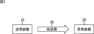
図1は、本技術を適用した伝送システムの一実施の形態の構成例を示すブロック図である。 FIG. 1 is a block diagram illustrating a configuration example of an embodiment of a transmission system to which the present technology is applied.
図1において、伝送システムは、送信装置10と受信装置20から構成される。
In FIG. 1, the transmission system includes a
送信装置10は、例えば、番組等のサービスの送信を行う。すなわち、送信装置10は、例えば、番組(テレビジョン放送番組)等のサービスを構成するコンポーネントとしての画像や音声のデータ等の送信の対象である対象データのストリームを、ディジタル放送信号として、伝送路30を介して送信(伝送)する。
The
受信装置20は、送信装置10から伝送路30を介して送信されてくるディジタル放送信号を受信し、元のストリームに復元して出力する。例えば、受信装置20は、番組等のサービスを構成するコンポーネントとしての画像や音声のデータを出力する。
The
なお、図1の伝送システムは、ATSC(Advanced Television Systems Committee standards)や、DVB(Digital Video Broadcasting),ISDB(Integrated Services Digital Broadcasting)等に準拠したデータ伝送、その他のデータ伝送に適用することができる。また、伝送路30としては、地上波や、衛星回線、ケーブルテレビジョン網(有線回線)等を採用することができる。
The transmission system of FIG. 1 can be applied to data transmission conforming to Advanced Television Systems Committee standards (ATSC), DVB (Digital Video Broadcasting), ISDB (Integrated Services Digital Broadcasting), and other data transmission. . Further, as the
<プロトコルスタック> <Protocol stack>
図2は、図1の伝送システムで行われる放送のプロトコルスタックの例を示す図である。 FIG. 2 is a diagram illustrating an example of a protocol stack for broadcasting performed in the transmission system of FIG.
すなわち、図2は、図1の伝送システムにおいて扱われるデータ(パケット及びフレーム)のデータ構造を示している。 That is, FIG. 2 shows the data structure of data (packets and frames) handled in the transmission system of FIG.
伝送システムでは、OSI(Open Systems Interconnection)参照モデルの第1層(物理層)L1、第2層(データリンク層)L2、及び、第3層(ネットワーク層)L3のデータが扱われる。 In the transmission system, data of the first layer (physical layer) L1, the second layer (data link layer) L2, and the third layer (network layer) L3 of the OSI (Open Systems Interconnection) reference model is handled.
図2において、IPパケット(IP Packet)は、第3層L3のデータであり、Genericパケット(Generic Packet)は、第2層L2のデータである。BBフレーム(Baseband Frame)、FECフレーム(FEC Frame)、及び、物理層フレーム(Physical Frame)は、第1層L1のデータである。 In FIG. 2, an IP packet (IP Packet) is data of the third layer L3, and a Generic packet (Generic Packet) is data of the second layer L2. The BB frame (Baseband Frame), the FEC frame (FEC Frame), and the physical layer frame (Physical Frame) are data of the first layer L1.
図1の伝送システムでは、データ放送が、IPパケットを用いて行われる。 In the transmission system of FIG. 1, data broadcasting is performed using IP packets.
IPパケットは、IPヘッダ(IP Header)とデータ(Data)とから構成される。IPパケットのデータには、画像や音声等のデータが配置される。 An IP packet is composed of an IP header and data. Data such as images and sounds are arranged in the IP packet data.
送信装置10では、IPパケットから、Genericパケットが構成(生成)される。
In the
Genericパケットは、Genericヘッダ(Generic Header)とペイロード(Payload)とから構成される。Genericパケットのペイロードには、1又は複数のIPパケットが配置される。 The generic packet is composed of a generic header and a payload. One or a plurality of IP packets are arranged in the payload of the generic packet.
送信装置10では、Genericパケットから、BBフレームが構成される。
In the
BBフレームは、BBヘッダ(Baseband Frame Header)とペイロード(Payload)とから構成される。BBフレームのペイロードには、1又は複数のGenericパケットが配置される。 The BB frame includes a BB header (Baseband Frame Header) and a payload (Payload). One or a plurality of generic packets are arranged in the payload of the BB frame.
送信装置10では、1又は複数のBBフレームの単位で、BBフレームが必要に応じてスクランブルされ、そのBBフレームに、物理層のエラー訂正用のパリティ(Parity)が付加されることで、FECフレームが構成される。
In the
さらに、送信装置10では、1又は複数のFECフレームの単位で、FECフレームに対して、ビットインターリーブや、コンスタレーション上の信号点へのマッピング、時間方向や周波数方向へのインターリーブ等の物理層の処理が必要に応じて行われる。そして、送信装置10では、物理層の処理後のFECフレームに、プリアンブルが付加され、物理層フレームが構成される。
Further, in the
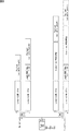
すなわち、物理層フレームは、プリアンブル(BS, Preamble)とペイロード(Payload)とから構成される。物理層フレームのペイロードには、FECフレームが配置される。 That is, the physical layer frame includes a preamble (BS, Preamble) and a payload (Payload). An FEC frame is arranged in the payload of the physical layer frame.
図2では、物理層フレームは、例えば、ATSC3.0のATSCフレームと同様に、プリアンブルとして、"BS(BootStrap)"と"Preamble"とを有する。 In FIG. 2, the physical layer frame has “BS (BootStrap)” and “Preamble” as preambles, for example, as in the ATSC 3.0 ATSC frame.
ここで、"BS"を、第1プリアンブルBSともいうこととするとともに、"Preamble"を、第2プリアンブルPreambleともいうこととする。 Here, “BS” is also referred to as a first preamble BS, and “Preamble” is also referred to as a second preamble preamble.
第1プリアンブルBSは、例えば、DVB-T.2のT2フレームを構成するP1シンボルに対応し、第2プリアンブルPreambleは、例えば、T2フレームを構成するP2シンボルに対応する。 The first preamble BS corresponds to, for example, a P1 symbol that configures a DVB-T.2 T2 frame, and the second preamble preamble corresponds to, for example, a P2 symbol that configures a T2 frame.
また、物理層フレームのペイロードは、例えば、例えば、T2フレームを構成するデータシンボルに対応する。 In addition, the payload of the physical layer frame corresponds to, for example, data symbols constituting a T2 frame.
DVB-T2やATSC3.0で用いられる物理層フレーム構造は、例えば、100msないし200ms以上程度の長さで構成される。物理層フレームについては、プリアンブルを処理した後に、その後のペイロードを処理することが可能となる。 The physical layer frame structure used in DVB-T2 and ATSC 3.0 is configured with a length of about 100 ms to 200 ms or more, for example. For the physical layer frame, it is possible to process the subsequent payload after processing the preamble.
すなわち、受信装置20は、物理層フレームを受信し、その物理層フレームのプリアンブルを復調する。さらに、受信装置20は、物理層フレームのプリアンブルを用いて、その物理層フレームのペイロードを処理し、物理層フレームから、FECフレーム、BBフレーム、Genericパケット、及び、IPパケットを、その順で復元する。
That is, the receiving
なお、物理層フレームのペイロードの処理には、その物理層フレームのプリアンブルが必要となる。そのため、受信装置20において、物理層フレームの途中から受信が開始された場合には、受信の開始後、次にプリアンブルが出現するまでの間に受信されたデータは破棄される。
Note that the processing of the payload of the physical layer frame requires the preamble of the physical layer frame. Therefore, when reception is started from the middle of the physical layer frame in the receiving
<時刻情報> <Time information>
図3は、時刻情報を説明する図である。 FIG. 3 is a diagram for explaining time information.
図1の伝送システムでは、図2で説明したように、送信装置10において、IPパケットから、物理層フレームが構成され、その物理層フレームのストリームが、受信装置20に送信される。
In the transmission system of FIG. 1, as described with reference to FIG. 2, in the
IPパケットでは、TSのPCRのような時刻情報が送信されない。そのため、送信装置10と受信装置20との間で同期をとるには、時刻情報を、物理層フレームのストリームに含めることが望ましい。
In IP packets, time information such as TS PCR is not transmitted. Therefore, in order to synchronize between the
そこで、送信装置10は、物理層フレームのストリームに、時刻情報を含めることができる。
Therefore, the
時刻情報は、図3に示すように、物理層フレームのプリアンブルに含めることができる。 The time information can be included in the preamble of the physical layer frame as shown in FIG.
ここで、物理層フレームのプリアンブルのうちの第1プリアンブルBSとしては、例えば、ATSC3.0では、30ないし40ビット程度が想定されている。したがって、第1プリアンブルBSは、時刻情報を含めるために十分なビット数でないことがある。 Here, as the first preamble BS in the preamble of the physical layer frame, for example, about 30 to 40 bits are assumed in ATSC3.0. Therefore, the first preamble BS may not be a sufficient number of bits to include time information.
そこで、時刻情報は、物理層フレームのプリアンブルのうちの第2プリアンブルPreambleに含めることができる。 Therefore, the time information can be included in the second preamble preamble among the preambles of the physical layer frame.
時刻情報は、物理層フレームのストリームにおける所定の位置の絶対的な時刻を表す。ストリームにおける所定の位置の時刻とは、所定の位置のビットが、送信装置10で処理されている最中の所定のタイミングの時刻である。所定の位置のビットが送信装置10で処理されている最中の所定のタイミングの時刻としては、例えば、送信装置10のあるブロックから、所定の位置のビットが出力されたときのタイミングの時刻や、送信装置10のあるブロックで、所定の位置のビットの処理が行われたタイミングの時刻等がある。
The time information represents an absolute time at a predetermined position in the physical layer frame stream. The time at a predetermined position in the stream is a time at a predetermined timing during which the bit at the predetermined position is being processed by the
ここで、時刻情報が時刻を表す物理層フレームのストリームにおける所定の位置を、時刻位置ということとする。 Here, a predetermined position in the stream of the physical layer frame whose time information indicates the time is referred to as a time position.
時刻位置としては、例えば、時刻情報が含まれるプリアンブルを有する物理層フレームの先頭の位置(第1プリアンブルBSの先頭の位置)を採用することができる。 As the time position, for example, the start position of the physical layer frame having the preamble including the time information (the start position of the first preamble BS) can be employed.
また、時刻位置としては、例えば、時刻情報が含まれるプリアンブルを有する物理層フレームの第1プリアンブルBSと第2プリアンブルPreambleとの境界の位置(第1プリアンブルBSの最後の位置)(第2プリアンブルPreambleの先頭の位置)を採用することができる。 As the time position, for example, the position of the boundary between the first preamble BS and the second preamble preamble (the last position of the first preamble BS) of the physical layer frame having the preamble including the time information (the second preamble preamble) Can be adopted.
さらに、時刻位置としては、例えば、時刻情報が含まれるプリアンブルを有する物理層フレームの第2プリアンブルPreambleの最後の位置を採用することができる。 Furthermore, as the time position, for example, the last position of the second preamble preamble of the physical layer frame having the preamble including the time information can be employed.
その他、時刻位置としては、物理層フレームの任意の位置を採用することができる。 In addition, any position of the physical layer frame can be adopted as the time position.
なお、物理層フレームにおいて、第1プリアンブルBSのサンプリング周波数と、第2プリアンブルPreamble以降のサンプリング周波数とは、異なることがあり得る。第1プリアンブルBSのサンプリング周波数と、第2プリアンブルPreamble以降のサンプリング周波数とが異なる場合、第1プリアンブルBSと、第2プリアンブルPreamble以降とでは、時刻のカウントの仕方が異なる。このため、時刻位置として、第1プリアンブルBSの先頭の位置を採用した場合、その時刻位置を基準とした時刻のカウントについては、第1プリアンブルBSと、第2プリアンブルPreamble以降とで、カウントの仕方を変更する必要があることがある。一方、時刻位置として、第2プリアンブルPreambleの先頭の位置を採用した場合、その時刻位置を基準とした時刻のカウント、すなわち、第2プリアンブルPreamble以降の時刻のカウントについては、そのカウントの仕方を変更する必要はない。 In the physical layer frame, the sampling frequency of the first preamble BS and the sampling frequency after the second preamble preamble may be different. When the sampling frequency of the first preamble BS is different from the sampling frequency after the second preamble preamble, the time counting method is different between the first preamble BS and the second preamble preamble. For this reason, when the first position of the first preamble BS is adopted as the time position, the time counting with respect to the time position is counted between the first preamble BS and the second and subsequent preambles. May need to be changed. On the other hand, when the start position of the second preamble preamble is adopted as the time position, the counting method is changed for the time count based on the time position, that is, the time count after the second preamble preamble. do not have to.
そこで、図3では、時刻位置として、時刻情報が含まれるプリアンブルを有する物理層フレームの第2プリアンブルPreambleの先頭の位置(第1プリアンブルBSと第2プリアンブルPreambleとの境界の位置)が採用されている。 Therefore, in FIG. 3, the position of the beginning of the second preamble preamble (the position of the boundary between the first preamble BS and the second preamble preamble) of the physical layer frame having the preamble including the time information is adopted as the time position. Yes.
プリアンブル(第1プリアンブルBS、第2プリアンブルPreamble)は、各物理層フレームの決まった位置、すなわち、例えば、先頭に存在し、物理層フレームを処理するにあたって、必ず、最初に処理される。したがって、受信装置20では、プリアンブルに含まれる時刻情報を、容易に取得して処理することができる。
The preamble (the first preamble BS and the second preamble) is present at a fixed position of each physical layer frame, that is, for example, at the head, and is always processed first when processing the physical layer frame. Therefore, the receiving
また、プリアンブルは、比較的ロバストに伝送されるので、そのようなプリアンブルに含まれる時刻情報も比較的ロバストに伝送することができる。 Also, since the preamble is transmitted relatively robustly, the time information included in such a preamble can also be transmitted relatively robustly.
ここで、時刻情報としては、例えば、NTP(Network Time Protocol)で規定されている時刻の情報や、3GPP(Third Generation Partnership Project)で規定されている時刻の情報、PTP(Precise Time Protocol)で規定される時刻の情報、GPS(Global Positioning System)情報に含まれる時刻の情報、その他独自に決定された形式の時刻の情報等の任意の時刻の情報を採用することができる。 Here, as the time information, for example, time information specified by NTP (Network Time Protocol), time information specified by 3GPP (Third Generation Partnership Project), PTP (Precise Time Protocol) It is possible to adopt any time information such as time information included, time information included in GPS (Global Positioning System) information, and other time information in a uniquely determined format.
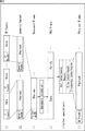
図4は、NTPパケットのフォーマットを示す図である。 FIG. 4 is a diagram showing the format of the NTP packet.
2ビットのLI(Leap Indicator)は、現在月の最後の1分に、うるう秒を挿入又は削除することを示す。3ビットのVN(Version Number)は、NTPのバージョンを示す。3ビットのModeは、NTPの動作モードを示す。 2-bit LI (Leap Indicator) indicates that a leap second is inserted or deleted in the last minute of the current month. A 3-bit VN (Version Number) indicates the NTP version. The 3-bit Mode indicates the NTP operation mode.
8ビットのStratumは、階層を示し、8ビットのPollは、ポーリング間隔として、連続するNTPメッセージの間隔(秒単位)を示す。8ビットのPrecisionは、システムクロックの精度(秒単位)を示す。 The 8-bit Stratum indicates a hierarchy, and the 8-bit Poll indicates a continuous NTP message interval (in seconds) as a polling interval. 8-bit Precision indicates the accuracy (in seconds) of the system clock.
Root Delayは、ルート遅延として、参照時刻までの往復の遅延をNTP短形式で示す。Root Dispersionは、参照時刻までの合計遅延の分散をNTP短形式で示す。Reference IDは、参照時刻を表す識別子を示す。放送システムでは、Reference IDには、NULLを示す"0000"を格納することができる。 Root Delay indicates the round trip delay until the reference time in the NTP short format as the root delay. Root Dispersion indicates the dispersion of the total delay until the reference time in NTP short format. Reference ID indicates an identifier representing a reference time. In the broadcast system, “0000” indicating NULL can be stored in the Reference ID.
Reference Timestampは、参照タイムスタンプとして、システム時刻が最後に補正された時刻をNTP長形式で示す。Origin Timestampは、開始タイムスタンプとして、クライアントからサーバへリクエスト送出したクライアントの時刻をNTP長形式で示す。放送システムでは、Origin Timestampには、"0"を格納することができる。 Reference Timestamp indicates the time when the system time was last corrected in the NTP long format as a reference time stamp. Origin Timestamp indicates the time of the client sending the request from the client to the server in the NTP length format as the start time stamp. In the broadcast system, “0” can be stored in the Origin Timestamp.
Receive Timestampは、受信タイムスタンプとして、クライアントからのリクエストを受信したサーバの時刻をNTP長形式で示す。放送システムでは、Receive Timestampには、"0"を格納する。Transmit Timestampは、送信タイムスタンプとして、クライアントへの応答を送出したサーバの時刻をNTP長形式で示す。 Receive Timestamp indicates the time of the server that received the request from the client in the NTP length format as a reception time stamp. In the broadcast system, “0” is stored in Receive Timestamp. Transmit Timestamp indicates the time of the server that sent the response to the client in the NTP length format as a transmission time stamp.
その他、NTPパケットは、拡張用のフィールドであるExtension Field 1や、Extension Field 2、さらには、Key Identifierやdgst(メッセージダイジェスト)を、必要に応じて有する。
In addition, the NTP packet has
時刻情報としては、NTPパケットのReference Timestamp等のタイムスタンプと同様の形式で表される64ビットの時刻の情報を採用することができる。 As the time information, 64-bit time information represented in the same format as a time stamp such as Reference Timestamp of an NTP packet can be adopted.
ここで、NTPパケットのタイムスタンプの64ビットの時刻については、リープ秒に起因して、時刻が不連続になる問題があるが、物理層フレームに含める時刻情報としては、十分な粒度がある。 Here, the 64-bit time of the time stamp of the NTP packet has a problem that the time becomes discontinuous due to the leap second, but the time information included in the physical layer frame has sufficient granularity.
また、時刻情報としては、NTPパケットのタイムスタンプの他、3GPPで規定されている時刻の情報、すなわち、例えば、3GPP TS 36 331において規定されている時刻の情報であるtimeInfo-r11を採用することができる。
As time information, in addition to the time stamp of the NTP packet, time information specified in 3GPP, that is, time information-r11 that is information on time specified in
timeInfo-r11は、39ビットのtimeInfoUTC-r11、2ビットのdayLightSavingTime-r11、8ビットのleapSeconds-r11、及び、7ビットのlocalTimeOffset-r11の56ビットで構成される。timeInfo-r11については、物理層フレームに含める時刻情報としては、粒度がやや不足気味ではあるが、リープ秒の問題は発生しない。 timeInfo-r11 is composed of 56 bits of 39 bits timeInfoUTC-r11, 2 bits dayLightSavingTime-r11, 8 bits leapSeconds-r11, and 7 bits localTimeOffset-r11. Regarding timeInfo-r11, the time information included in the physical layer frame is slightly insufficient in granularity, but the problem of leap seconds does not occur.
その他、時刻情報としては、PTPで規定される時刻の情報、すなわち、PTPパケットについて、IEEE1588で規定されている時刻を表す80ビットを採用することができる。PTPパケットの時刻を表す80ビットについては、その80ビットのうちの48ビットが、秒単位の時刻を表し、残りの32ビットがナノ秒単位の時刻を表す。したがって、PTPで規定される時刻の情報は、物理層フレームに含める時刻情報としては、十分な粒度があり、正確な時刻を表すことができる。時刻情報は、受信装置20で正確な時刻を再生する観点から、より正確な時刻を表すことが望ましく、PTPで規定される時刻の情報を、物理層フレームに含める時刻情報として採用した場合には、正確な時刻情報を伝送し、受信装置20で正確な時刻を再生することができる。さらに、PTPで規定される時刻の情報については、リープ秒の問題は発生しない。
In addition, as the time information, it is possible to adopt time information defined by PTP, that is, 80 bits representing the time defined by IEEE 1588 for the PTP packet. Of the 80 bits representing the time of the PTP packet, 48 of the 80 bits represent the time in seconds, and the remaining 32 bits represent the time in nanoseconds. Therefore, the time information defined by PTP has sufficient granularity as time information included in the physical layer frame, and can represent an accurate time. It is desirable that the time information represents a more accurate time from the viewpoint of reproducing the accurate time by the receiving
<時刻情報の配置位置> <Time information location>
図5は、時刻情報の配置位置の例を説明する図である。 FIG. 5 is a diagram for explaining an example of an arrangement position of time information.
図3では、時刻情報を、物理層フレームのプリアンブルに配置する(含める)こととしたが、時刻情報は、物理層フレームのプリアンブルの他、例えば、物理層フレームのペイロードに配置することができる。 In FIG. 3, the time information is arranged (included) in the preamble of the physical layer frame. However, the time information can be arranged in the payload of the physical layer frame, for example, in addition to the preamble of the physical layer frame.
図5では、時刻情報が、物理層フレームのペイロードの先頭部分に配置されている。 In FIG. 5, time information is arranged at the beginning of the payload of the physical layer frame.
時刻情報を、物理層フレームのペイロードの先頭部分に配置する場合には、受信装置20では、物理層フレームのプリアンブル(第1プリアンブルBS、第2プリアンブルPreamble)の処理後に、ペイロードの先頭に配置された時刻情報を取得することができる。
When the time information is arranged at the beginning of the payload of the physical layer frame, the receiving
<時刻情報をペイロードに配置する場合の第1の配置例> <First Arrangement Example when Time Information is Arranged in Payload>
図6は、時刻情報を、物理層フレームのペイロードの先頭に配置する場合の第1の配置例を説明する図である。 FIG. 6 is a diagram for explaining a first arrangement example when the time information is arranged at the head of the payload of the physical layer frame.
第1の配置例では、時刻情報は、物理層フレームのペイロードの先頭としての、物理層フレームのペイロードの先頭のBBフレームの先頭のGenericパケットのペイロードに配置される。 In the first arrangement example, the time information is arranged in the payload of the generic packet at the beginning of the BB frame at the beginning of the payload of the physical layer frame as the beginning of the payload of the physical layer frame.
図6は、Genericパケットの構成例を示している。 FIG. 6 shows a configuration example of a generic packet.
図6のGenericパケットにおいて、Genericヘッダの先頭には、3ビットのタイプ情報(Type)が設定される。このタイプ情報には、Genericパケットのペイロードに配置されるデータのタイプに関する情報が設定される。 In the generic packet of FIG. 6, 3-bit type information (Type) is set at the head of the generic header. In this type information, information on the type of data arranged in the payload of the generic packet is set.
Genericパケットのペイロードに、時刻情報、その他、シグナリングのためのシグナリング情報が配置される場合、Genericヘッダのタイプ情報には、例えば、"100"が設定される。また、Genericヘッダにおいて、"100"が設定されたタイプ情報の次は、1ビットのリザーブド領域(Res:Reserved)とされ、その次に、1ビットのヘッダモード(HM:Header Mode)が配置される。 When time information and other signaling information for signaling are arranged in the payload of the generic packet, for example, “100” is set in the type information of the generic header. In the generic header, the type information set to “100” is followed by a 1-bit reserved area (Res: Reserved), followed by a 1-bit header mode (HM: Header Mode). The
ヘッダモードとして、"0"が設定された場合、それに続いて、11ビットのレングス情報(Length(LSB))が配置される。このレングス情報は、Genericパケットのペイロードの長さに設定される。一方、ヘッダモードとして、"1"が設定された場合、それに続いて、11ビットのレングス情報(Length(LSB))と、5ビットのレングス情報(Length(MSB))との合計16ビットのレングス情報が配置され、さらに、3ビットのリザーブド領域(Res)が設けられる。 When “0” is set as the header mode, 11-bit length information (Length (LSB)) is subsequently placed. This length information is set to the length of the payload of the generic packet. On the other hand, when “1” is set as the header mode, a total of 16 bits of 11-bit length information (Length (LSB)) and 5-bit length information (Length (MSB)) follows. Information is arranged, and a 3-bit reserved area (Res) is further provided.
ヘッダモードとして"0"が設定された場合、レングス情報(Length(LSB))は、11ビットであり、その11ビットのレングス情報によって、Genericパケットのペイロードの長さとして、0〜2047(=211-1)バイトの範囲の値を表すことができる。しかしながら、11ビットのレングス情報では、2048バイト以上のペイロードの長さを表すことができない。そこで、ペイロードに、2048バイト以上のデータが配置される場合には、ヘッダモードとして"1"が設定される。この場合、Genericヘッダの領域として1バイト(8ビット)が追加され、レングス情報が、16ビットとなる。この16ビットのレングス情報によって、2048バイト以上のペイロードの長さを表すことができる。 When "0" is set as the header mode, the length information (Length (LSB)) is 11 bits, and the length of the payload of the generic packet is 0 to 2047 (= 2) based on the 11-bit length information. 11 -1) Can represent a range of bytes. However, 11-bit length information cannot represent a payload length of 2048 bytes or more. Therefore, when data of 2048 bytes or more is arranged in the payload, “1” is set as the header mode. In this case, 1 byte (8 bits) is added as a generic header area, and the length information is 16 bits. This 16-bit length information can represent a payload length of 2048 bytes or more.
Genericパケットにおいては、以上のように構成されるGenericヘッダに続いて、ペイロードが配置される。ここでは、Genericヘッダのタイプ情報として、"100"が設定されているため、ペイロードには、時刻情報を含むシグナリング情報が配置される。 In the generic packet, the payload is arranged following the generic header configured as described above. Here, since “100” is set as the type information of the Generic header, signaling information including time information is arranged in the payload.
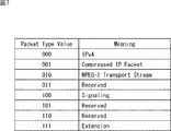
図7は、図6のGenericパケットのタイプ情報を説明する図である。 FIG. 7 is a diagram for explaining the type information of the generic packet in FIG.
GenericパケットのペイロードにIPv4のIPパケットが配置される場合、タイプ情報には、"000"が設定される。また、ペイロードに、圧縮されたIPパケットが配置される場合、タイプ情報には、"001"が設定される。さらに、ペイロードに、MPEG2-TS方式のTSパケットが配置される場合、タイプ情報には、"010"が設定される。 When an IPv4 IP packet is arranged in the payload of the generic packet, “000” is set in the type information. When a compressed IP packet is placed in the payload, “001” is set in the type information. Furthermore, when an MPEG2-TS TS packet is placed in the payload, “010” is set in the type information.
また、ペイロードに、時刻情報等のシグナリング情報が配置される場合には、タイプ情報には、"100"が設定される。なお、図7において、"011","101","110"の3値のタイプ情報は、未定義(Reserved)となっている。また、3値の未定義(Reserved)だけでは、タイプ情報の拡張に不足が生じる場合には、タイプ情報に、"111"を設定することで、タイプ情報(の領域)を、さらに拡張することができる。 When signaling information such as time information is arranged in the payload, “100” is set in the type information. In FIG. 7, the ternary type information “011”, “101”, and “110” is undefined (Reserved). In addition, if there is a shortage of expansion of type information with only three undefined (Reserved), set "111" in the type information to further expand the type information (area). Can do.
<時刻情報をペイロードに配置する場合の第2の配置例> <Second arrangement example when time information is arranged in the payload>
図8は、時刻情報を、物理層フレームのペイロードの先頭に配置する場合の第2の配置例を説明する図である。 FIG. 8 is a diagram for explaining a second arrangement example when the time information is arranged at the head of the payload of the physical layer frame.
第2の配置例では、時刻情報は、物理層フレームのペイロードの先頭としての、物理層フレームのペイロードの先頭のBBフレームの先頭のGenericパケットのヘッダに配置される。 In the second arrangement example, the time information is arranged in the header of the generic packet at the beginning of the BB frame at the beginning of the payload of the physical layer frame as the beginning of the payload of the physical layer frame.
図8は、Genericパケットの構成例を示している。 FIG. 8 shows a configuration example of a generic packet.
図6で説明したように、Genericパケットにおいて、Genericヘッダの先頭の3ビットのタイプ情報(Type)には、Genericパケットのペイロードに配置されるデータのタイプに関するタイプ情報が設定される。 As described with reference to FIG. 6, in the generic packet, type information regarding the type of data arranged in the payload of the generic packet is set in the type information (Type) of the top three bits of the generic header.
第2の配置例では、Genericヘッダにおいて、3ビットのタイプ情報には、"000","001",又は"010"が設定される。 In the second arrangement example, “000”, “001”, or “010” is set in the 3-bit type information in the Generic header.
図7で説明したように、タイプ情報として、"000"が設定された場合、ペイロードには、IPv4のIPパケットが配置され、"001"が設定された場合、ペイロードには、圧縮されたIPパケットが配置される。また、タイプ情報として、"010"が設定された場合、ペイロードには、TSパケットが配置される。 As described in FIG. 7, when “000” is set as type information, an IPv4 IP packet is placed in the payload, and when “001” is set, compressed IP is included in the payload. Packets are placed. When “010” is set as type information, a TS packet is arranged in the payload.
Genericヘッダにおいて、"000","001",又は"010"が設定されたタイプ情報の次には、1ビットのパケット設定情報PC(Packet Configuration)が配置される。パケット設定情報PCとして、"0"が設定された場合、Genericヘッダはノーマルモード(Normal mode)となって、その次に配置されるヘッダモード(HM)に応じて、11ビットのレングス情報(Length)、又は、16ビットのレングス情報及び3ビットのリザーブド領域(Res)が配置される。そして、Genericヘッダに続くペイロードには、Genericヘッダのタイプ情報に応じて、IPv4のIPパケット、圧縮されたIPパケット、又はTSパケットが配置される。 Following the type information in which “000”, “001”, or “010” is set in the Generic header, 1-bit packet setting information PC (Packet Configuration) is arranged. When "0" is set as the packet setting information PC, the Generic header is in the normal mode (Normal mode), and the 11-bit length information (Length) is set according to the header mode (HM) to be placed next. Or 16-bit length information and 3-bit reserved area (Res). In the payload following the Generic header, an IPv4 IP packet, a compressed IP packet, or a TS packet is arranged according to the type information of the Generic header.
一方、パケット設定情報PCとして、"1"が設定された場合には、Genericヘッダはシグナリングモード(Signaling mode)となって、その次に配置されるヘッダモード(HM)に応じて、レングス情報(Length)が配置される。すなわち、ヘッダモードとして、"0"が設定された場合、それに続いて、11ビットのレングス情報(Length(LSB))が配置される。さらに、Genericヘッダが拡張されて、レングス情報の次に、時刻情報を含むシグナリング情報(Signaling)が配置される。 On the other hand, when “1” is set as the packet setting information PC, the generic header becomes the signaling mode (Signaling mode), and the length information (HM) is set according to the header mode (HM) to be placed next. Length) is placed. That is, when “0” is set as the header mode, 11-bit length information (Length (LSB)) is subsequently placed. Further, the Generic header is expanded, and signaling information (Signaling) including time information is arranged next to the length information.
また、パケット設定情報PCとして"1"が設定された場合に、ヘッダモード(HM)として"1"が設定されているときには、ヘッダモードに続いて、16ビットのレングス情報(Length)と3ビットのリザーブド領域(Res)が配置される。さらに、Genericヘッダが拡張されて、リザーブド領域(Res)の次に、時刻情報を含むシグナリング情報(Signaling)が配置される。 When "1" is set as the packet setting information PC and "1" is set as the header mode (HM), 16-bit length information (Length) and 3 bits are set following the header mode. Reserved areas (Res) are arranged. Further, the Generic header is expanded, and signaling information (Signaling) including time information is arranged next to the reserved area (Res).
以上のシグナリング情報までを、Genericヘッダ(拡張ヘッダ)として、その後に、ペイロードが配置される。ペイロードには、Genericヘッダのタイプ情報に応じて、IPv4や圧縮されたIPパケット等が配置される。 Up to the above signaling information, the generic header (extension header) is used, and then the payload is arranged. In the payload, IPv4, a compressed IP packet, or the like is arranged according to the type information of the Generic header.
<時刻情報をペイロードに配置する場合の第3の配置例> <Third arrangement example when time information is arranged in the payload>
図9は、時刻情報を、物理層フレームのペイロードの先頭に配置する場合の第3の配置例を説明する図である。 FIG. 9 is a diagram for explaining a third arrangement example when the time information is arranged at the head of the payload of the physical layer frame.
第3の配置例では、時刻情報は、物理層フレームのペイロードの先頭としての、物理層フレームのペイロードの先頭のBBフレームのBBヘッダに配置される。 In the third arrangement example, the time information is arranged in the BB header of the BB frame at the head of the payload of the physical layer frame as the head of the payload of the physical layer frame.
図9は、BBフレームの構成例を示している。 FIG. 9 shows a configuration example of the BB frame.
図9において、BBフレームは、BBヘッダとペイロード(Payload)から構成される。BBヘッダには、1又は2バイトのヘッダ(Header)が配置される。さらに、BBヘッダには、1又は2バイトのオプショナルフィールド(Optional Field)と、拡張フィールド(Extension Field)とを配置することができる。 In FIG. 9, the BB frame is composed of a BB header and a payload. A 1-byte or 2-byte header (Header) is arranged in the BB header. Furthermore, a 1- or 2-byte optional field (Optional Field) and an extension field (Extension Field) can be arranged in the BB header.
ヘッダ(Header)の先頭には、1ビットのモード(MODE)が設定される。 A 1-bit mode (MODE) is set at the head of the header.
1ビットのモード(MODE)として、"0"が設定された場合、ヘッダには、モードの後に、7ビットのポインタ情報(Pointer(LSB))のみが配置される。なお、ポインタ情報は、BBフレームのペイロードに配置されるGenericパケットの位置を示すための情報である。例えば、あるBBフレームの最後に配置されたGenericパケットのデータが、次のBBフレームにまたがって配置される場合に、ポインタ情報として、次のBBフレームの先頭に配置されるGenericパケットの位置情報を設定することができる。 When “0” is set as the 1-bit mode (MODE), only 7-bit pointer information (Pointer (LSB)) is placed in the header after the mode. The pointer information is information for indicating the position of the generic packet arranged in the payload of the BB frame. For example, when the data of a generic packet placed at the end of a certain BB frame is placed across the next BB frame, the location information of the generic packet placed at the beginning of the next BB frame is used as pointer information. Can be set.
また、モード(MODE)として、"1"が設定された場合、ヘッダには、モードの後に、7ビットのポインタ情報(Pointer(LSB))と、6ビットのポインタ情報(Pointer(MSB))と、2ビットのオプショナルフラグ(OPTI:OPTIONAL)とが配置される。オプショナルフラグは、オプショナルフィールド(Optional Field)と、拡張フィールド(Extension Field)を配置して、BBヘッダを拡張するかどうかを示す。 When "1" is set as the mode (MODE), the header contains 7-bit pointer information (Pointer (LSB)) and 6-bit pointer information (Pointer (MSB)) after the mode. , A 2-bit optional flag (OPTI: OPTIONAL) is arranged. The optional flag indicates whether to extend the BB header by arranging an optional field and an extension field.
オプショナルフィールドと拡張フィールドの拡張を行わない場合、オプショナルフラグには、"00"が設定される。 When the optional field and the extended field are not expanded, “00” is set in the optional flag.
オプショナルフィールドの拡張のみを行う場合、オプショナルフラグには、"01"又は"10"が設定される。なお、オプショナルフラグとして"01"が設定された場合、オプショナルフィールドには、1バイト(8ビット)のパディングが行われる。また、オプショナルフラグとして"10"が設定された場合、オプショナルフィールドには、2バイト(16ビット)のパディングが行われる。 When only the optional field is expanded, “01” or “10” is set in the optional flag. When “01” is set as the optional flag, 1 byte (8 bits) of padding is performed in the optional field. When “10” is set as the optional flag, the optional field is padded with 2 bytes (16 bits).
オプショナルフィールドと拡張フィールドの拡張を行う場合、オプショナルフラグには、"11"が設定される。この場合、オプショナルフィールドの先頭には、3ビットの拡張タイプ情報(TYPE(EXT_TYPE))が設定される。この拡張タイプ情報には、拡張タイプ情報の次に配置される拡張レングス情報(EXT_Length)と拡張フィールドのタイプ(Extension type)に関する情報が設定される。 When the optional field and the extended field are expanded, “11” is set in the optional flag. In this case, 3-bit extension type information (TYPE (EXT_TYPE)) is set at the head of the optional field. In this extension type information, information on extension length information (EXT_Length) and extension field type (Extension type) arranged next to the extension type information is set.
第3の配置例では、拡張フィールド(拡張ヘッダ)に、時刻情報を含むシグナリング情報が配置される。 In the third arrangement example, signaling information including time information is arranged in the extension field (extension header).
すなわち、第3の配置例では、オプショナルフラグ(OPTI)として"11"が設定され、オプショナルフィールドと拡張フィールドの拡張が行われる。さらに、オプショナルフィールドの拡張タイプ情報(TYPE(EXT_TYPE))として"011"が設定され、拡張フィールドに、時刻情報を含むシグナリング情報が配置される。 That is, in the third arrangement example, “11” is set as the optional flag (OPTI), and the optional field and the extended field are expanded. Furthermore, “011” is set as the extension type information (TYPE (EXT_TYPE)) of the optional field, and signaling information including time information is arranged in the extension field.
図10は、図9の拡張タイプ情報(TYPE(EXT_TYPE))を説明する図である。 FIG. 10 is a diagram for explaining the extension type information (TYPE (EXT_TYPE)) of FIG.
拡張タイプ情報には、その拡張タイプ情報の次に配置される拡張レングス情報(EXT_Length)と拡張フィールドのタイプ(Extension type)に関する情報が設定される。 In the extension type information, information related to extension length information (EXT_Length) and extension field type (Extension type) arranged next to the extension type information is set.
すなわち、拡張タイプ情報(EXT_TYPE)の後に、拡張レングス情報(EXT_Length)を配置し、拡張フィールド(Extension Field)に、スタッフィングバイト(Stuffing Bytes)のみが配置される場合、拡張タイプ情報には、"000"が設定される。 That is, when extension length information (EXT_Length) is arranged after extension type information (EXT_TYPE) and only stuffing bytes (Stuffing Bytes) are arranged in the extension field (Extension Field), the extension type information includes “000 "Is set.
拡張タイプ情報(EXT_TYPE)の後に、拡張レングス情報(EXT_Length)を配置せずに、拡張フィールド(Extension Field)に、ISSY(Input Stream Synchronizer)が配置される場合、拡張タイプ情報には、"001"が設定される。 When an ISSY (Input Stream Synchronizer) is placed in the extension field (Extension Field) without placing the extension length information (EXT_Length) after the extension type information (EXT_TYPE), the extension type information contains "001" Is set.
拡張タイプ情報(EXT_TYPE)の後に、拡張レングス情報(EXT_Length)を配置し、拡張フィールド(Extension Field)に、ISSYとともに、スタッフィングバイトが配置される場合、拡張タイプ情報には、"010"が設定される。 When extension length information (EXT_Length) is placed after extension type information (EXT_TYPE), and stuffing bytes are placed in the extension field (Extension Field) together with ISSY, "010" is set in the extension type information. The
拡張タイプ情報(EXT_TYPE)の後に、拡張レングス情報(EXT_Length)を配置し、拡張フィールド(Extension Field)に、時刻情報を含むシグナリング情報が配置される場合、拡張タイプ情報には、"011"が設定される。この場合、スタッフィングバイトを配置するかどうかは任意である。なお、図10において、"100"ないし"111"の拡張タイプ情報は、未定義(Reserved)となっている。 When extension length information (EXT_Length) is placed after extension type information (EXT_TYPE) and signaling information including time information is placed in the extension field (Extension Field), "011" is set in the extension type information Is done. In this case, it is arbitrary whether or not the stuffing byte is arranged. In FIG. 10, the extension type information “100” to “111” is undefined (Reserved).
以上のように、時刻情報は、物理層フレームのペイロードの先頭に配置することができる。 As described above, the time information can be arranged at the head of the payload of the physical layer frame.
<送信装置10の構成例>
<Configuration Example of Transmitting
図11は、図1の送信装置10の構成例を示すブロック図である。
FIG. 11 is a block diagram illustrating a configuration example of the
図11において、送信装置10は、時刻情報取得部61、記述子生成部62、プリアンブル生成部63、コンポーネント取得部64、エンコーダ65、フレーム生成部66、送信部67、及び、アンテナ68を有する。
In FIG. 11, the
時刻情報取得部61は、時刻情報を取得し、記述子生成部62に供給する。時刻情報の取得は、以下のようにして行われる。すなわち、BBフレームの構成に必要なパケットが、図示せぬスケジューラに到着すると、フレーム生成部66でのBBフレームが生成されるときの時刻tから、そのBBフレームを含んで構成される物理層フレームが求められ、その物理層フレームの第2プリアンブルPreambleの先頭の時刻Tが求められる。そして、時刻Tは、スケジューラからコントロール信号として、時刻情報取得部61に供給される。なお、時刻情報は、SFN同期に用いることができる。
The time
記述子生成部62は、時刻情報取得部61からの時刻情報を含む時刻情報記述子を生成し、プリアンブル生成部63に供給する
The
プリアンブル生成部63は、記述子生成部62からの時刻情報記述子を、例えば、第2プリアンブルPreambleに含めたプリアンブル(第1プリアンブルBS、第2プリアンブルPreamble)を生成し、フレーム生成部66に供給する。
The
コンポーネント取得部64は、サービス(例えば、番組)を構成するコンポーネントとしての画像や音声のデータを取得し、エンコーダ65に供給する。
The
すなわち、コンポーネント取得部64は、例えば、既に収録されたコンテンツの保管場所から、放送時間帯に応じて該当するコンテンツを取得し、あるいはスタジオやロケーション場所からライブのコンテンツを取得し、そのコンテンツ(のデータ)を、エンコーダ65に供給する。
That is, for example, the
エンコーダ65は、コンポーネント取得部64から供給される画像や音声のデータを、所定の符号化方式に従って符号化し、例えば、IPパケットの形で、フレーム生成部66に供給する。
The
フレーム生成部66は、プリアンブル生成部63からのプリアンブル、及び、エンコーダ64からのIPパケットを適宜用いて、物理層フレームを生成(構成)し、送信部67に供給する。
The
すなわち、フレーム生成部66は、図2で説明したように、エンコーダ65からのIPパケットを配置したGenericパケットを構成する。さらに、フレーム生成部66は、GenericパケットをBBフレームのペイロードに配置したBBフレームを構成する。
That is, the
また、フレーム生成部66は、BBフレームからFECフレームを構成し、必要な処理を施して、物理層フレームのペイロードに配置する。
Also, the
そして、フレーム生成部66は、物理層フレームのペイロードに、プリアンブル生成部63からのプリアンブルを付加することで、物理層フレームを構成し、送信部67に供給する。
Then, the
送信部67は、フレーム生成部66からの物理層フレームのディジタル変調やアップコンバート等の処理を行い、アンテナ68を介して、ディジタル放送信号として送信する。
The
なお、図11の送信装置10において、すべての機能ブロックが、物理的に単一の装置内に配置される必要はなく、少なくとも一部の機能ブロックが、他の機能ブロックとは物理的に独立した装置として構成されるようにしてもよい。
In addition, in the
<送信処理> <Transmission process>
図12は、図11の送信装置10が行う送信処理の例を説明するフローチャートである。
FIG. 12 is a flowchart illustrating an example of transmission processing performed by the
ステップS11において、時刻情報取得部61は、時刻情報を取得し、記述子生成部62に供給して、処理は、ステップS12に進む。
In step S11, the time
ステップS12では、記述子生成部62は、時刻情報取得部61からの時刻情報を必要に応じて含む時刻情報記述子を生成し、プリアンブル生成部63に供給して、処理は、ステップS13に進む。
In step S12, the
ステップS13では、プリアンブル生成部63は、記述子生成部62からの時刻情報記述子を、第2プリアンブルPreambleに含めた物理層フレームのプリアンブルを生成し、フレーム生成部66に供給して、処理は、ステップS14に進む。
In step S13, the
ステップS14では、コンポーネント取得部64は、サービスを構成するコンポーネントとしての画像や音声のデータを取得し、エンコーダ65に供給する。
In step S <b> 14, the
エンコーダ65は、コンポーネント取得部64から供給される画像や音声のデータの符号化等の処理を行い、IPパケットの形で、フレーム生成部66に供給して、処理は、ステップS14からステップS15に進む。
The
ステップS15では、フレーム生成部66は、プリアンブル生成部63からのプリアンブル、及び、エンコーダ64からのIPパケットを適宜用いて、物理層フレームを生成し、送信部67に供給して、処理は、ステップS16に進む。
In step S15, the
ステップS16では、送信部67は、フレーム生成部66からの物理層フレームを、アンテナ68を介して、ディジタル放送信号として送信する。
In step S <b> 16, the
<受信装置20の構成例>
<Configuration Example of Receiving
図13は、図1の受信装置20の構成例を示すブロック図である。
FIG. 13 is a block diagram illustrating a configuration example of the
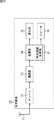
図13において、受信装置20は、アンテナ71、チューナ72、復調部73、処理部74、表示部75、及び、スピーカ76から構成される。
In FIG. 13, the
アンテナ71は、送信装置10からのディジタル放送信号を受信し、チューナ72に供給する。
The
チューナ72は、アンテナ71からのディジタル放送信号から、所定の周波数チャンネルの成分を選局することで、その周波数チャンネルで送信されてくる物理層フレームを受信し、復調部73に供給する。
The
復調部73は、チューナ72から供給される物理層フレームの復調処理を行う。
The
すなわち、復調部73は、物理層フレームのプリアンブル(第1プリアンブルBS、第2プリアンブルPreamble)を復調し、さらに、そのプリアンブルの復調結果を必要に応じて用いて、物理層フレームのペイロードを復調する。
That is, the
また、復調部73は、物理層フレームのペイロードの復調によって得られるFECフレームを復調(復号)する。
The
そして、復調部73は、FECフレームの復調の結果得られるBBフレームから、Genericパケットを復調し、そのGenericパケットから、IPパケットを復調して、処理部74に供給する。
The
また、復調部73は、復調処理において、物理層フレームのプリアンブルに含まれる時刻情報記述子を取得し、処理部74に供給する。
Further, the
処理部74は、復調部73からのIPパケットから番組の画像や音声を復号し、画像を表示部75に供給するとともに、音声をスピーカ76に供給する。
The
また、処理部74は、時刻情報取得部81を有する。時刻情報取得部81は、復調部73からの時刻情報記述子から、時刻情報を必要に応じて取得する。処理部74は、時刻情報取得部81が取得した時刻情報を用いて、必要な処理を行う。
In addition, the
すなわち、処理部74(又は復調部73)は、時刻情報を用いて、例えば、クロックデータリカバリを行い、送信装置10との同期をとる同期処理等を行う。また、処理部74は、時刻情報を用いて、画像や音声等のプレゼンテーションのタイミングを制御するタイミング制御処理等を行う。なお、時刻情報は、その他、例えば、DVB-T.2のSFN同期のような同期等に適用することができる。
That is, the processing unit 74 (or the demodulation unit 73) performs, for example, clock data recovery using the time information, and performs a synchronization process for synchronizing with the
表示部75は、処理部74からの画像を表示する。スピーカ76は、処理部74からの音声を出力する。
The
なお、図13の受信装置20においては、表示部75及びスピーカ76が内蔵されている構成を説明したが、表示部75及びスピーカ76は、外部に設けてもよい。
In the receiving
<受信処理> <Reception processing>
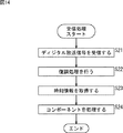
図14は、図13の受信装置20が行う受信処理を説明するフローチャートである。
FIG. 14 is a flowchart illustrating a reception process performed by the
ステップS21において、チューナ72は、アンテナ71からのディジタル放送信号から、物理層フレームを受信し、復調部73に供給して、処理は、ステップS22に進む。
In step S21, the
ステップS22では、復調部73は、チューナ72から供給される物理層フレームの復調処理を行い、その結果得られるIPパケットや、時刻情報記述子を、処理部74に供給して、処理は、ステップS23に進む。
In step S22, the
ステップS23では、処理部74の時刻情報取得部81が、復調部73からの時刻情報記述子から、時刻情報を取得し、処理は、ステップS24に進む。ここで、処理部74では、時刻情報取得部81が取得した時刻情報を用いて、送信装置10との同期をとる同期処理等が行われる。
In step S23, the time
ステップS24では、処理部74は、送信装置10との同期がとられた状態の下で、復調部73からのIPパケットに含まれるコンポーネントを処理する。すなわち、処理部74は、復調部73からのIPパケットから番組の画像や音声を復号し、画像を表示部75に供給して表示させるとともに、音声をスピーカ76に供給して出力させる。
In step S <b> 24, the
以上のように、図1の伝送システムでは、送信装置10が、物理層フレームのプリアンブルに、時刻情報(を含む時刻情報記述子)を含めて送信するので、時刻情報を効率的に伝送することができる。
As described above, in the transmission system of FIG. 1, the
さらに、図1の伝送システムでは、受信装置20が、物理層フレームのプリアンブルに含まれる(時刻情報記述子に含まれる)時刻情報を用いて、処理を行うので、迅速に処理を行うことができる。
Furthermore, in the transmission system of FIG. 1, the receiving
<PTP> <PTP>
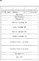
図15は、時刻情報として用いることができるPTPで規定される時刻の情報(以下、単に、PTPともいう)を説明する図である。 FIG. 15 is a diagram illustrating time information (hereinafter also simply referred to as PTP) defined by PTP that can be used as time information.
PTPは、IEEE1588で規定されており、80ビットで構成される。 PTP is defined by IEEE 1588 and consists of 80 bits.
80ビットのPTPは、秒単位の時刻を表す48ビットの秒フィールド(secondsField)と、ナノ秒単位の時刻を表す32ビットのナノ秒フィールド(nanosecondsField)とから構成される。 The 80-bit PTP is composed of a 48-bit second field (secondsField) representing time in seconds and a 32-bit nanosecond field (nanosecondsField) representing time in nanoseconds.
秒フィールドの1は、1秒を表し、ナノ秒フィールドの1は、1ナノ秒を表す。 1 in the second field represents 1 second, and 1 in the nanosecond field represents 1 nanosecond.
したがって、例えば、+2.000000001秒を表すPTPでは、秒フィールドは、0x000000000002となり、ナノ秒フィールドは、0x00000001となる。なお、0xは、その後に続く値が16進数であることを表す。 Therefore, for example, in PTP representing +2.000000001 seconds, the second field is 0x000000000002, and the nanosecond field is 0x00000001. Note that 0x indicates that the subsequent value is a hexadecimal number.
ここで、109ナノ秒は、1秒であるため、ナノ秒フィールドは、0ないし109未満の値をとる。 Here, since 10 9 nanoseconds is 1 second, the nanosecond field takes a value from 0 to less than 10 9 .
すなわち、ナノ秒フィールドの最大値は、109-1である。109-1は、30ビットで表現することができるので、32ビットのナノ秒フィールドの上位2ビットは、常時0となる。 That is, the maximum value of the nanosecond field is 10 9 -1. Since 10 9 -1 can be represented by 30 bits, the upper 2 bits of the 32-bit nanosecond field are always 0.
IEEE1588では、PTPが表す時刻の起点であるエポック(epoch)が、国際原子時(TAI( International Atomic Time)の1970年1月1日の0時であることが規定されている。すなわち、IEEE1588のPTPは、TAIの1970年1月1日の0時をエポックとする時刻を表す。 IEEE1588 stipulates that the epoch, which is the starting point of the time represented by PTP, is 0 o'clock on January 1, 1970, TAI (International Atomic Time). PTP represents the time when the epoch is 0:00 on January 1, 1970, TAI.
図4で説明したように、PTPを、物理層フレームに含める時刻情報として採用した場合には、正確な時刻情報を伝送し、受信装置10で正確な時刻を再生することができ、リープ秒の問題の発生を防止することができる。
As described with reference to FIG. 4, when PTP is adopted as time information included in the physical layer frame, accurate time information can be transmitted, and the accurate time can be reproduced by the receiving
ところで、PTPによれば、極めて正確な時刻を表現することができるが、図1の伝送システムで放送を行う場合に、その放送に必要以上の精度の時刻情報を伝送することは、伝送帯域を圧迫し、効率的でない。 By the way, according to PTP, it is possible to express a very accurate time. However, when broadcasting is performed with the transmission system of FIG. Squeezed and inefficient.
80ビットのPTPは、放送によるサービスの提供にとって、十分過ぎる精度の時刻情報であり、PTPの情報量を、ある程度低下させても、放送によるサービスの提供を十分維持することができる。 The 80-bit PTP is time information that is accurate enough for the provision of services by broadcasting, and even if the amount of PTP information is reduced to some extent, the provision of services by broadcasting can be sufficiently maintained.
そこで、図1の伝送システムでは、時刻情報としてのPTPを、その情報量を低下させて伝送することができる。 Therefore, in the transmission system of FIG. 1, it is possible to transmit PTP as time information with a reduced amount of information.
PTPの情報量を低下させる方法としては、例えば、PTPの伝送頻度を低下させる方法や、PTPを圧縮する方法がある。 As a method for reducing the information amount of PTP, for example, there are a method for reducing the transmission frequency of PTP and a method for compressing PTP.
ここで、時刻情報は、図5ないし図10で説明したように、物理層フレームのプリアンブルではなく、ペイロードに含めることができるが、以下では、時刻情報を、物理層フレームのプリアンブルに含める場合を例として、説明を行う。 Here, as described with reference to FIGS. 5 to 10, the time information can be included in the payload instead of the physical layer frame preamble. In the following, the time information is included in the physical layer frame preamble. An explanation will be given as an example.
<PTPの伝送頻度を低下させる方法> <Method to reduce PTP transmission frequency>
図16は、PTPの伝送頻度を低下させる方法の例を説明する図である。 FIG. 16 is a diagram for explaining an example of a method for reducing the transmission frequency of PTP.
時刻情報としてのPTPは、すべての物理層フレームに含めることができるが、受信装置20において、送信装置10との同期を、必要とされる精度でとるのに、すべての物理層フレーム(の第2プリアンブルPreamble)に、PTPを含める必要がない場合がある。
The PTP as time information can be included in all physical layer frames. However, in order to synchronize with the transmitting
そこで、PTPは、すべての物理層フレームに含めるのではなく、一部の物理層フレームだけに含めることができ、これにより、PTPの伝送頻度を低下させることができる。 Therefore, PTP can be included in only some physical layer frames, not in all physical layer frames, thereby reducing the transmission frequency of PTP.
図16では、4フレームの物理層フレームごとに、その4フレームの物理層フレームのうちの先頭の物理層フレーム(の第2プリアンブルPreamble)にだけ、時刻情報としてのPTPが挿入されて伝送されている。 In FIG. 16, for every four physical layer frames, a PTP as time information is inserted and transmitted only in the first physical layer frame (second preamble preamble) of the four physical layer frames. Yes.
この場合、送信装置10から受信装置20に伝送するPTPの情報量を、約1/4に低下させ、PTPを、効率的に伝送することができる。
In this case, the information amount of PTP transmitted from the
<PTPを圧縮する方法> <How to compress PTP>
図17は、PTPを圧縮する方法の例を説明する図である。 FIG. 17 is a diagram illustrating an example of a method for compressing PTP.
PTPの48ビットの秒フィールドによれば、約892万年の広範囲な時刻を表現することができるが、放送については、そこまで広範囲な時刻は、必要とされない。 According to the 48-bit second field of PTP, a wide range of time of about 8.92 million years can be expressed. However, for broadcasting, a wide range of time is not required.
ここで、例えば、米国では、アナログ放送は、約80年で第1世代ディジタル放送方式(ATSC)に切り替えられた。また、第1世代ディジタル放送方式(ATSC)は、放送開始から約30年程度で第2世代ディジタル放送方式(ATSC3.0)に置き換わる見込みである。 Here, for example, in the United States, analog broadcasting has been switched to the first generation digital broadcasting system (ATSC) in about 80 years. The first generation digital broadcasting system (ATSC) is expected to be replaced with the second generation digital broadcasting system (ATSC 3.0) in about 30 years from the start of broadcasting.
かかる現状に鑑みて、図1の伝送システムによる放送が、例えば、2016年から90年間程度使用されると仮定した場合、物理層フレームに含められる時刻情報としては、2106年程度までの時刻をカウントすることができれば、十分である。 In view of the current situation, assuming that the broadcast by the transmission system in FIG. 1 is used for about 90 years from 2016, for example, the time information included in the physical layer frame is counted up to about 2106. If it can be done, it is enough.
PTPのエポックとして、IEEE1588に規定されているエポック(以下、標準エポックともいう)は、1970年(1月1日の0時)であるので、2106年までの時刻をカウントするには、136=2106-1970年間の時刻をカウントすることができれば良い。 As the epoch of PTP, the epoch specified in IEEE1588 (hereinafter also referred to as the standard epoch) is 1970 (0 o'clock on January 1), so to count the time until 2106, 136 = It is only necessary to be able to count 2106-1970 years.
136年間の秒数は、32ビットでカウントすることができるので、2106年までの時刻を、PTPでカウントする場合には、秒フィールドは、32ビットで十分である。 Since the number of seconds for 136 years can be counted by 32 bits, when the time up to 2106 is counted by PTP, 32 bits is sufficient for the seconds field.
また、PTPのエポックとして、標準エポックではなく、独自に決定したエポック(以下、独自エポックともいう)を採用した場合には、秒フィールドとしては、さらに、少ないビット数を採用し得る。 In addition, when a uniquely determined epoch (hereinafter also referred to as a unique epoch) is adopted as the PTP epoch, a smaller number of bits can be adopted as the second field.
すなわち、例えば、31ビットで、秒をカウントする場合には、約68年間の秒数をカウントすることができる。いま、独自エポックとして、例えば、2016年を用いることとすると、秒フィールドとして、31ビットを採用した場合には、2084=2016+68年までの時刻をカウントすることができる。 That is, for example, when counting seconds with 31 bits, the number of seconds for about 68 years can be counted. Assuming that 2016 is used as the unique epoch, for example, when 31 bits are used as the second field, the time up to 2084 = 2016 + 68 can be counted.
したがって、図1の伝送システムによる放送が、例えば、2016年から、2080年程度まで使用されると仮定した場合には、2016年(1月1日)を、独自エポックとして用いることにより、秒フィールドとしては、31ビットを採用することができる。 Therefore, if it is assumed that the broadcasting by the transmission system of FIG. 1 is used from 2016 to about 2080, by using 2016 (January 1) as a unique epoch, the second field As an example, 31 bits can be adopted.
ここで、以上をまとめると、以下のようになる。 Here, the above is summarized as follows.
すなわち、秒フィールドとして、32ビットを採用した場合には、約136年間の秒数をカウントすることができる。かかる秒フィールドによれば、標準エポックを採用した場合には、2106(=1970+136)年までの時刻をカウントすることができ、2016年を独自エポックとして採用した場合には、2152(=2016+136)年までの時刻をカウントすることができる。 That is, when 32 bits are adopted as the second field, the number of seconds for about 136 years can be counted. According to the second field, when standard epochs are adopted, the time up to 2106 (= 1970 + 136) can be counted, and when 2016 is adopted as an original epoch, 2152 (= 2016 +136) Can count time up to the year.
また、秒フィールドとして、31ビットを採用した場合には、約68年間の秒数をカウントすることができる。かかる秒フィールドによれば、標準エポックを採用した場合には、2038(=1970+68)年までの時刻をカウントすることができ、2016年を独自エポックとして採用した場合には、2084(=2016+68)年までの時刻をカウントすることができる。 If 31 bits are used as the second field, the number of seconds for about 68 years can be counted. According to such a second field, when standard epochs are adopted, the time up to 2038 (= 1970 + 68) can be counted, and when 2016 is adopted as an original epoch, 2084 (= 2016 +68) Can count the time until the year.
以上から、図1の伝送システムによる放送が行われる期間として、どの程度の期間を見積もるかによるが、秒フィールドは、例えば、31ビットや32ビット程度で、十分であると予想される。 From the above, depending on what period is estimated as the period during which broadcasting by the transmission system of FIG. 1 is performed, for example, about 31 bits or 32 bits are expected to be sufficient for the second field.
一方、PTPのナノ秒フィールドは、ナノ秒単位の時刻を表すので、最高で、1GHz(の周波数)のクロックをカウントすることができるが、放送については、そこまで高速なクロック(のカウント)は、必要とされない。 On the other hand, since the nanosecond field of PTP represents the time in nanosecond units, it can count clocks of 1 GHz (frequency) at the maximum, but for broadcasting, the clock (counting) is so fast Not needed.
ここで、32ビットのナノ秒フィールドによれば、1GHzのクロックをカウントすることができる。すなわち、32ビットのナノ秒フィールドによれば、1GHzのクロックに同期して、1ns(=1/(1GHz))に対応する20ずつ値を増加しながら、0x0ないし0x3b9ac9ff(=109-1)の値が繰り返しカウントされる。
Here, according to the 32-bit nanosecond field, a 1 GHz clock can be counted. That is, according to the
また、例えば、32ビットのナノ秒フィールドの下位5ビットを削除した27ビットのナノ秒フィールドによれば、32.25MHz=1GHz/25のクロックをカウントすることができる。すなわち、27ビットのナノ秒フィールドによれば、32ビット換算では、32.25MHzのクロックに同期して、25ns(=1/(32.25MHz))に対応する25ずつ値を増加しながら、0x0ないし0x3b9ac9e0(=109-25)の値が繰り返しカウントされる。
Further, for example, according to the 27 bits nanosecond field remove the lower 5 bits of nanoseconds field 32 bits, it is possible to count the clock of 32.25MHz = 1GHz / 2 5. That is, according to the
さらに、例えば、32ビットのナノ秒フィールドの下位13ビットを削除した19ビットのナノ秒フィールドによれば、122.0...kHz=1GHz/213のクロックをカウントすることができる。すなわち、19ビットのナノ秒フィールドによれば、32ビット換算では、122.0...kHzのクロックに同期して、213ns(=1/(122.0...kHz))に対応する213ずつ値を増加しながら、0x0ないし0x3b9aa000(=109-213)の値が繰り返しカウントされる。
Further, for example, according to the 19-bit nanosecond field obtained by deleting the lower 13 bits of the 32-bit nanosecond field, the clock of 122.0... KHz = 1 GHz / 2 13 can be counted. That is, according to the
放送では、一般に、90kHzや27MHz程度のクロックが採用される。 In broadcasting, a clock of about 90 kHz or 27 MHz is generally used.
32.25MHzのクロックをカウントすることができる27ビットのナノ秒フィールドによれば、27MHzのクロックの精度を確保することができる。122.0...kHzのクロックをカウントすることができる19ビットのナノ秒フィールドによれば、90kHzのクロックの精度を確保することができる。 According to the 27-bit nanosecond field that can count 32.25 MHz clock, the accuracy of 27 MHz clock can be ensured. According to the 19-bit nanosecond field that can count 122.0 ... kHz clock, 90kHz clock accuracy can be ensured.
したがって、90kHzや27MHz程度のクロックを採用する放送では、ナノ秒フィールドを、例えば、その下位5ビットや13ビットを削除して、27ビットや19ビットとしても、十分な精度を確保することができる。 Therefore, in broadcasting that uses a clock of about 90 kHz or 27 MHz, it is possible to ensure sufficient accuracy even if the nanosecond field is, for example, 27 bits or 19 bits by deleting the lower 5 bits or 13 bits. .
なお、図15で説明したように、ナノ秒フィールドの上位2ビットは、常時0であるため、下位5ビットや下位13ビットを削除した27ビットや19ビットのナノ秒フィールドについては、さらに、上位2ビットを削除し、25ビットや17ビットのナノ秒フィールドとすることができる。 As explained in FIG. 15, since the upper 2 bits of the nanosecond field are always 0, the 27-bit and 19-bit nanosecond fields from which the lower 5 bits and the lower 13 bits are deleted are further Two bits can be deleted to make a 25-bit or 17-bit nanosecond field.
図17は、秒フィールドを、32ビットに圧縮するとともに、ナノ秒フィールドを19ビットに圧縮する場合の、PTPの圧縮の例を示している。 FIG. 17 shows an example of PTP compression when the second field is compressed to 32 bits and the nanosecond field is compressed to 19 bits.
送信装置10(図11)においては、時刻情報取得部61から記述子生成部62に、48ビットの秒フィールドと、32ビットのナノ秒フィールドとで構成される80ビットのPTPが供給される。
In the transmission device 10 (FIG. 11), the time
記述子生成部62は、48ビットの秒フィールドの、例えば、上位16ビットを削除することにより、48ビットの秒フィールドを、32ビットの秒フィールド(以下、圧縮秒フィールドともいう)に圧縮する。
The
さらに、記述子生成部62は、32ビットのナノ秒フィールドの、例えば、下位13ビットを削除することにより、32ビットのナノ秒フィールドを、19ビットのナノ秒フィールド(以下、圧縮ナノ秒フィールドともいう)に圧縮する。
Further, the
そして、記述子生成部62は、32ビットの圧縮秒フィールドと、19ビットの圧縮ナノ秒フィールドとに圧縮された51ビットのPTP(以下、圧縮PTPともいう)を、時刻情報記述子に含め、プリアンブル生成部63(図11)に供給する。
Then, the
以上のように、PTPを圧縮する方法では、PTPの秒フィールド及びナノ秒フィールドそれぞれの一部のビットが削除されることにより、PTPが、いわば中間フォーマットの圧縮PTP(圧縮時刻情報)に圧縮されて伝送される。 As described above, in the method of compressing PTP, the PTP is compressed into compressed PTP (compression time information) in an intermediate format by deleting some bits of each of the second field and nanosecond field of PTP. Is transmitted.
受信装置20(図13)では、時刻情報取得部81が、時刻情報記述子に含まれる圧縮PTPを取得し、その圧縮PTPを、IEEE1588に規定するフォーマットのPTPに復元する。
In the receiving device 20 (FIG. 13), the time
すなわち、時刻情報取得部81は、圧縮PTPの32ビットの圧縮秒フィールドの上位ビットとして、16ビットの0を付加(追加)することで、32ビットの圧縮秒フィールドを、48ビットの秒フィールドに復元する。
That is, the time
さらに、時刻情報取得部81は、圧縮PTPの19ビットの圧縮ナノ秒フィールドの下位ビットとして、13ビットの0を付加することで、19ビットの圧縮ナノ秒フィールドを、32ビットのナノ秒フィールドに復元する。
Further, the time
そして、時刻情報取得部81は、48ビットの秒フィールドと、32ビットのナノ秒フィールドとで構成される、IEEE1588に規定するフォーマットのPTPに復元する。
Then, the time
なお、記述子生成部62では、32ビットのナノ秒フィールドの、下位13ビットを削除するとともに、上述したように、常時0になっている上位2ビットを削除し、32ビットのナノ秒フィールドを、17ビットの圧縮ナノ秒フィールドに圧縮することができる。
The
この場合、時刻情報取得部81では、17ビットの圧縮ナノ秒フィールドの下位ビットとして、13ビットの0を付加するとともに、上位ビットとして、2ビットの0を付加することで、17ビットの圧縮ナノ秒フィールドが、32ビットのナノ秒フィールドに復元される。
In this case, the time
また、PTPのエポックとして、標準エポックではなく、独自エポックを採用する場合には、記述子生成部62は、標準エポックと独自エポックとの差分(独自エポック−標準エポック)に対応する時間(以下、差分時間ともいう)を、PTPから減算してから、その減算後のPTPを、圧縮PTPに圧縮する。
In addition, when adopting a unique epoch instead of a standard epoch as a PTP epoch, the
さらに、この場合、時刻情報取得部81は、圧縮秒フィールド及び圧縮ナノ秒フィールドを、秒フィールド及びナノ秒フィールドに復元した後に、その復元後の秒フィールド及びナノ秒フィールドに、差分時間を加算することで、IEEE1588に規定するフォーマットのPTP(標準エポックのPTP)を復元する。
Furthermore, in this case, the time
<圧縮モード> <Compression mode>
図18は、PTPを圧縮する圧縮モードの例を示す図である。 FIG. 18 is a diagram illustrating an example of a compression mode for compressing PTP.
図18では、圧縮モードは、4ビットで表され、モード0ないし15の16種類の圧縮モードを定義することができる。
In FIG. 18, the compression mode is represented by 4 bits, and 16 types of compression modes of
なお、図18では、モード3及び7ないし15は、未定義(Reserved)になっており、実質的には、6種類の圧縮モードが定義されている。
In FIG. 18,
モード0では、PTPは、圧縮されず、48ビットの秒フィールドと、32ビットのナノ秒フィールドとで構成されるPTPが用いられる。また、モード0では、PTPのエポックとして、標準エポックが用いられる。
In
モード1では、48ビットの秒フィールドが、上位16ビットを削除することにより、32ビットの秒フィールドに圧縮されるとともに、32ビットのナノ秒フィールドが、下位13ビットを削除することにより、19ビットのナノ秒フィールドに圧縮される。また、モード1では、PTPのエポックとして、標準エポックが用いられる。
In
モード2では、48ビットの秒フィールドが、上位16ビットを削除することにより、32ビットの秒フィールドに圧縮されるとともに、32ビットのナノ秒フィールドが、下位5ビットを削除することにより、27ビットのナノ秒フィールドに圧縮される。また、モード2では、PTPのエポックとして、標準エポックが用いられる。
In
モード4では、PTPは、圧縮されず、48ビットの秒フィールドと、32ビットのナノ秒フィールドとで構成されるPTPが用いられる。また、モード4では、PTPのエポックとして、独自エポックが用いられる。
In
モード5では、48ビットの秒フィールドが、上位17ビットを削除することにより、31ビットの秒フィールドに圧縮されるとともに、32ビットのナノ秒フィールドが、下位13ビットを削除することにより、19ビットのナノ秒フィールドに圧縮される。また、モード5では、PTPのエポックとして、独自エポックが用いられる。
In
モード6では、48ビットの秒フィールドが、上位17ビットを削除することにより、31ビットの秒フィールドに圧縮されるとともに、32ビットのナノ秒フィールドが、下位5ビットを削除することにより、27ビットのナノ秒フィールドに圧縮される。また、モード6では、PTPのエポックとして、独自エポックが用いられる。
In
圧縮モードは、例えば、送信装置10側において、秒フィールド及びナノ秒フィールドについて、放送に必要なビット数を見積もって決定される。
The compression mode is determined, for example, by estimating the number of bits required for broadcasting for the second field and nanosecond field on the
なお、図17で説明したように、ナノ秒フィールドについては、下位ビットの他、上位2ビットを削除して、圧縮することができる。 As described with reference to FIG. 17, the nanosecond field can be compressed by deleting the upper 2 bits in addition to the lower bits.
ナノ秒フィールドの、下位ビット及び上位2ビットを削除する圧縮モードは、図18において、未定義になっているモードのいずれかに割り当てることができる。
The compression mode for deleting the low-order bits and the high-
<時刻情報記述子のシンタクス> <Syntax of time information descriptor>
図19は、時刻情報記述子のシンタクスの第1の例を示す図である。 FIG. 19 is a diagram illustrating a first example of syntax of a time information descriptor.
図19においてtime_info_flagは、時刻情報としてのPTP(圧縮PTP)の有無を表す時刻情報フラグであり、値0は、PTPが存在することを表し、値1は、PTPが存在しないことを表す。
In FIG. 19, time_info_flag is a time information flag indicating the presence or absence of PTP (compressed PTP) as time information, a
本実施の形態では、time_info_flagとして、1ビットのフラグを採用するが、time_info_flagには、2ビット以上を割り当てることができる。 In the present embodiment, a 1-bit flag is adopted as time_info_flag, but 2 bits or more can be assigned to time_info_flag.
time_info_flagが、0である場合、時刻情報記述子には、PTPが含まれず、time_info_flagが、1である場合、時刻情報記述子には、PTPが含まれる。 When time_info_flag is 0, the time information descriptor does not include PTP, and when time_info_flag is 1, the time information descriptor includes PTP.
例えば、図16に示したように、4フレームの物理層フレームごとに、その4フレームの物理層フレームのうちの先頭の物理層フレームにだけ、時刻情報としてのPTPを挿入する場合には、その先頭の物理層フレームに含める時刻情報記述子のtime_info_flagが1にされ、残りの3フレームの物理層フレームに含める時刻情報記述子のtime_info_flagが0にされる。 For example, as shown in FIG. 16, for each physical layer frame of 4 frames, when inserting PTP as time information only in the top physical layer frame of the 4 physical layer frames, The time_info_flag of the time information descriptor included in the first physical layer frame is set to 1, and the time_info_flag of the time information descriptor included in the remaining three physical layer frames is set to 0.
図19において、PTP_seconsFieldは、PTPの秒フィールドを表し、PTP_nanosecondsFieldは、PTPのナノ秒フィールドを表す。 In FIG. 19, PTP_seconsField represents a PTP second field, and PTP_nanosecondsField represents a PTP nanosecond field.
図19では、圧縮モード(図18)がモード1の圧縮PTPが採用されており、そのため、PTP_seconsFieldが、32ビットになっており、PTP_nanosecondsFieldが、19ビットになっている。
In FIG. 19, compressed PTP with the compression mode (FIG. 18) of
図19のシンタクスは、圧縮モードを、モード1等の所定のモードに固定する場合に使用される。
The syntax in FIG. 19 is used when the compression mode is fixed to a predetermined mode such as
なお、圧縮モードは、モード1以外のモードに固定することができる。圧縮モードを、どのモードに固定するかは、例えば、放送規格で規定することができる。
The compression mode can be fixed to a mode other than
図20は、時刻情報記述子のシンタクスの第2の例を示す図である。 FIG. 20 is a diagram illustrating a second example of the syntax of the time information descriptor.
図20において、time_info_flagは、図19で説明した時刻情報フラグである。 In FIG. 20, time_info_flag is the time information flag described in FIG.
図20では、time_info_flagが、0である場合、時刻情報記述子には、圧縮モード及びPTPが含まれず、time_info_flagが、1である場合、時刻情報記述子には、圧縮モード及びPTPが含まれる。 In FIG. 20, when time_info_flag is 0, the time information descriptor does not include the compression mode and PTP, and when time_info_flag is 1, the time information descriptor includes the compression mode and PTP.
図20において、modeは、圧縮モードを表す。 In FIG. 20, mode represents a compression mode.
modeが0又は4である場合、時刻情報記述子には、図18で説明したように、48ビットの秒フィールド(PTP_secondsField)と、32ビットのナノ秒フィールド(PTP_nanosecondsField)とで構成されるPTPが含まれる。 When mode is 0 or 4, the time information descriptor includes a PTP composed of a 48-bit second field (PTP_secondsField) and a 32-bit nanosecond field (PTP_nanosecondsField) as described in FIG. included.
modeが1である場合、時刻情報記述子には、図18で説明したように、32ビットの圧縮秒フィールド(PTP_secondsField)と、19ビットの圧縮ナノ秒フィールド(PTP_nanosecondsField)とで構成される圧縮PTPが含まれる。 When mode is 1, the time information descriptor includes a compressed PTP composed of a 32-bit compressed second field (PTP_secondsField) and a 19-bit compressed nanosecond field (PTP_nanosecondsField) as described in FIG. Is included.
modeが2である場合、時刻情報記述子には、図18で説明したように、32ビットの圧縮秒フィールド(PTP_secondsField)と、27ビットの圧縮ナノ秒フィールド(PTP_nanosecondsField)とで構成される圧縮PTPが含まれる。 When mode is 2, as described in FIG. 18, the time information descriptor includes a compressed PTP composed of a 32-bit compressed second field (PTP_secondsField) and a 27-bit compressed nanosecond field (PTP_nanosecondsField). Is included.
modeが5である場合、時刻情報記述子には、図18で説明したように、31ビットの圧縮秒フィールド(PTP_secondsField)と、19ビットの圧縮ナノ秒フィールド(PTP_nanosecondsField)とで構成される圧縮PTPが含まれる。 When mode is 5, as described in FIG. 18, the time information descriptor includes a compressed PTP composed of a 31-bit compressed second field (PTP_secondsField) and a 19-bit compressed nanosecond field (PTP_nanosecondsField). Is included.
modeが6である場合、時刻情報記述子には、図18で説明したように、31ビットの圧縮秒フィールド(PTP_secondsField)と、27ビットの圧縮ナノ秒フィールド(PTP_nanosecondsField)とで構成される圧縮PTPが含まれる。 When mode is 6, as described in FIG. 18, the time information descriptor includes a compressed PTP composed of a 31-bit compressed second field (PTP_secondsField) and a 27-bit compressed nanosecond field (PTP_nanosecondsField). Is included.
図20のシンタクスは、圧縮モードを必要に応じて選択可能とする場合に使用される。 The syntax in FIG. 20 is used when the compression mode can be selected as necessary.
なお、図19及び図20の時刻情報記述子は、時刻情報フラグであるtime_info_flagを含めずに構成することができる。 Note that the time information descriptors of FIGS. 19 and 20 can be configured without including time_info_flag which is a time information flag.
時刻情報記述子に、time_info_flagが含まれない場合、時刻情報としての(圧縮)PTPは、すべての物理層フレームで伝送される。 When time_info_flag is not included in the time information descriptor, (compressed) PTP as time information is transmitted in all physical layer frames.
ここで、以上のように、PTPの伝送頻度を低下させる方法や、PTPを圧縮する方法は、時刻情報として、PTP以外の、NTPで規定されている時刻の情報や、3GPPで規定されている時刻の情報、GPS情報に含まれる時刻の情報、その他独自に決定された形式の時刻の情報等の任意の時刻の情報にも適用することができる。 Here, as described above, the method of reducing the transmission frequency of PTP and the method of compressing PTP are time information other than PTP, time information defined by NTP, and 3GPP. The present invention can also be applied to arbitrary time information such as time information, time information included in GPS information, and other time information in a uniquely determined format.
なお、以上においては、図1の伝送システムにおいて、IPパケットを伝送することとしたが、IPパケット以外の、例えば、TSパケット等を伝送することができる。 In the above description, the IP system transmits the IP packet in the transmission system of FIG. 1. However, for example, a TS packet other than the IP packet can be transmitted.
また、図1の伝送システムは、例えば、ATSC3.0や、DVB,ISDB等の任意のデータ伝送に適用することができる。 Further, the transmission system of FIG. 1 can be applied to arbitrary data transmission such as ATSC 3.0, DVB, ISDB, and the like.
<DVB-T.2の物理層フレーム> <Physical layer frame of DVB-T.2>
図21は、DVB-T.2の物理層フレームであるT2フレーム(T2frame)の構成を示す図である。 FIG. 21 is a diagram illustrating a configuration of a T2 frame (T2frame) that is a physical layer frame of DVB-T.2.
T2フレームは、プリアンブルとしてのP1及びP2と、ペイロードとしてのデータシンボル(Data Symbols)とを有する。 The T2 frame includes P1 and P2 as preambles and data symbols (Data Symbols) as payloads.
P1は、P1 signalingを有し、P2は、L1-pre signaling及びL1-post signalingを有する。 P1 has P1 signaling, and P2 has L1-pre signaling and L1-post signaling.
L1-post signalingは、Configurable, Dynamic, Extension, CRC, L1 paddingを有する。 L1-post signaling has Configurable, Dynamic, Extension, CRC, and L1 padding.
時刻情報記述子は、以上のようなT2フレームのプリアンブル(のうちの、例えば、P2)に含めることができる。 The time information descriptor can be included in the preamble (for example, P2) of the T2 frame as described above.
<本技術を適用したコンピュータの説明> <Description of computer to which this technology is applied>
次に、送信装置10や受信装置20の一連の処理は、ハードウェアにより行うこともできるし、ソフトウェアにより行うこともできる。一連の処理をソフトウェアによって行う場合には、そのソフトウェアを構成するプログラムが、コンピュータにインストールされる。
Next, a series of processing of the
図22は、上述した一連の処理を実行するプログラムがインストールされるコンピュータの一実施の形態の構成例を示すブロック図である。 FIG. 22 is a block diagram illustrating a configuration example of an embodiment of a computer in which a program for executing the series of processes described above is installed.
プログラムは、コンピュータに内蔵されている記録媒体としてのハードディスク105やROM103に予め記録しておくことができる。
The program can be recorded in advance on a
あるいはまた、プログラムは、リムーバブル記録媒体111に格納(記録)しておくことができる。このようなリムーバブル記録媒体111は、いわゆるパッケージソフトウエアとして提供することができる。ここで、リムーバブル記録媒体111としては、例えば、フレキシブルディスク、CD-ROM(Compact Disc Read Only Memory),MO(Magneto Optical)ディスク,DVD(Digital Versatile Disc)、磁気ディスク、半導体メモリ等がある。
Alternatively, the program can be stored (recorded) in the
なお、プログラムは、上述したようなリムーバブル記録媒体111からコンピュータにインストールする他、通信網や放送網を介して、コンピュータにダウンロードし、内蔵するハードディスク105にインストールすることができる。すなわち、プログラムは、例えば、ダウンロードサイトから、ディジタル衛星放送用の人工衛星を介して、コンピュータに無線で転送したり、LAN(Local Area Network)、インターネットといったネットワークを介して、コンピュータに有線で転送することができる。
In addition to installing the program from the
コンピュータは、CPU(Central Processing Unit)102を内蔵しており、CPU102には、バス101を介して、入出力インタフェース110が接続されている。
The computer incorporates a CPU (Central Processing Unit) 102, and an input /
CPU102は、入出力インタフェース110を介して、ユーザによって、入力部107が操作等されることにより指令が入力されると、それに従って、ROM(Read Only Memory)103に格納されているプログラムを実行する。あるいは、CPU102は、ハードディスク105に格納されたプログラムを、RAM(Random Access Memory)104にロードして実行する。
The
これにより、CPU102は、上述したフローチャートにしたがった処理、あるいは上述したブロック図の構成により行われる処理を行う。そして、CPU102は、その処理結果を、必要に応じて、例えば、入出力インタフェース110を介して、出力部106から出力、あるいは、通信部108から送信、さらには、ハードディスク105に記録等させる。
Thus, the
なお、入力部107は、キーボードや、マウス、マイク等で構成される。また、出力部106は、LCD(Liquid Crystal Display)やスピーカ等で構成される。
The
ここで、本明細書において、コンピュータがプログラムに従って行う処理は、必ずしもフローチャートとして記載された順序に沿って時系列に行われる必要はない。すなわち、コンピュータがプログラムに従って行う処理は、並列的あるいは個別に実行される処理(例えば、並列処理あるいはオブジェクトによる処理)も含む。 Here, in the present specification, the processing performed by the computer according to the program does not necessarily have to be performed in time series in the order described as the flowchart. That is, the processing performed by the computer according to the program includes processing executed in parallel or individually (for example, parallel processing or object processing).
また、プログラムは、1のコンピュータ(プロセッサ)により処理されるものであっても良いし、複数のコンピュータによって分散処理されるものであっても良い。さらに、プログラムは、遠方のコンピュータに転送されて実行されるものであっても良い。 Further, the program may be processed by one computer (processor) or may be distributedly processed by a plurality of computers. Furthermore, the program may be transferred to a remote computer and executed.
さらに、本明細書において、システムとは、複数の構成要素(装置、モジュール(部品)等)の集合を意味し、すべての構成要素が同一筐体中にあるか否かは問わない。したがって、別個の筐体に収納され、ネットワークを介して接続されている複数の装置、及び、1つの筐体の中に複数のモジュールが収納されている1つの装置は、いずれも、システムである。 Furthermore, in this specification, the system means a set of a plurality of components (devices, modules (parts), etc.), and it does not matter whether all the components are in the same housing. Accordingly, a plurality of devices housed in separate housings and connected via a network and a single device housing a plurality of modules in one housing are all systems. .
なお、本技術の実施の形態は、上述した実施の形態に限定されるものではなく、本技術の要旨を逸脱しない範囲において種々の変更が可能である。 The embodiments of the present technology are not limited to the above-described embodiments, and various modifications can be made without departing from the gist of the present technology.
例えば、本技術は、1つの機能をネットワークを介して複数の装置で分担、共同して処理するクラウドコンピューティングの構成をとることができる。 For example, the present technology can take a configuration of cloud computing in which one function is shared by a plurality of devices via a network and is jointly processed.
また、上述のフローチャートで説明した各ステップは、1つの装置で実行する他、複数の装置で分担して実行することができる。 In addition, each step described in the above flowchart can be executed by being shared by a plurality of apparatuses in addition to being executed by one apparatus.
さらに、1つのステップに複数の処理が含まれる場合には、その1つのステップに含まれる複数の処理は、1つの装置で実行する他、複数の装置で分担して実行することができる。 Further, when a plurality of processes are included in one step, the plurality of processes included in the one step can be executed by being shared by a plurality of apparatuses in addition to being executed by one apparatus.
また、本明細書に記載された効果はあくまで例示であって限定されるものではなく、他の効果があってもよい。 Moreover, the effect described in this specification is an illustration to the last, and is not limited, There may exist another effect.
なお、本技術は、以下のような構成をとることができる。 In addition, this technique can take the following structures.
<1>
プリアンブルとペイロードとを有する物理層フレームのストリームにおける所定の位置の時刻を表す時刻情報の有無を表す時刻情報フラグを含み、
前記時刻情報フラグが、前記時刻情報があることを表す場合に、前記時刻情報を、さらに含む
時刻情報記述子を、前記プリアンブルに含む前記物理層フレームを生成する生成部と、
前記物理層フレームを送信する送信部と
を備える送信装置。
<2>
前記時刻情報記述子は、前記時刻情報を圧縮した圧縮時刻情報を含む
<1>に記載の送信装置。
<3>
前記時刻情報の1ビット以上の下位ビットを削除することにより、前記時刻情報を、前記圧縮時刻情報に圧縮する
<2>に記載の送信装置。
<4>
前記時刻情報の1ビット以上の、値が0の上位ビットを削除することにより、前記時刻情報を、前記圧縮時刻情報に圧縮する
<2>又は<3>に記載の送信装置。
<5>
前記時刻情報記述子は、前記時刻情報の圧縮モードをさらに含む
<2>ないし<4>のいずれかに記載の送信装置。
<6>
前記プリアンブルは、第1プリアンブルと、前記第1プリアンブルに続く第2プリアンブルとを有し、
前記時刻情報記述子は、前記第2プリアンブルに含まれ、
前記時刻情報記述子に含まれる時刻情報は、前記第2プリアンブルの先頭の位置の時刻を表す
<1>ないし<5>のいずれかに記載の送信装置。
<7>
前記時刻情報は、
NTP(Network Time Protocol)で規定される時刻の情報、
3GPP(Third Generation Partnership Project)で規定される時刻の情報、
又は、PTP(Precise Time Protocol)で規定される時刻の情報である
<2>ないし<6>のいずれかに記載の送信装置。
<8>
前記PTPで規定される時刻の情報を構成する48ビットの秒フィールド、及び、32ビットのナノ秒フィールドのうちの前記秒フィールドの1ビット以上の上位ビットを削除するとともに、前記ナノ秒フィールドの1ビット以上の下位ビットを削除することにより、前記時刻情報を、前記圧縮時刻情報に圧縮する
<7>に記載の送信装置。
<9>
前記ナノ秒フィールドの上位2ビットを、さらに削除することにより、前記時刻情報を、前記圧縮時刻情報に圧縮する
<8>に記載の送信装置。
<10>
プリアンブルとペイロードとを有する物理層フレームのストリームにおける所定の位置の時刻を表す時刻情報の有無を表す時刻情報フラグを含み、
前記時刻情報フラグが、前記時刻情報があることを表す場合に、前記時刻情報を、さらに含む
時刻情報記述子を、前記プリアンブルに含む前記物理層フレームを生成することと、
前記物理層フレームを送信することと
を含む送信方法。
<11>
プリアンブルとペイロードとを有する物理層フレームのストリームにおける所定の位置の時刻を表す時刻情報の有無を表す時刻情報フラグを含み、
前記時刻情報フラグが、前記時刻情報があることを表す場合に、前記時刻情報を、さらに含む
時刻情報記述子を、前記プリアンブルに含む前記物理層フレームを受信する受信部と、
前記物理層フレームのプリアンブルに含まれる前記時刻情報記述子に含まれる時刻情報を用いて、処理を行う処理部と
を備える受信装置。
<12>
前記時刻情報記述子は、前記時刻情報を圧縮した圧縮時刻情報を含む
<11>に記載の受信装置。
<13>
前記圧縮時刻情報は、前記時刻情報の1ビット以上の下位ビットを削除することにより圧縮されている
<12>に記載の受信装置。
<14>
前記圧縮時刻情報は、前記時刻情報の1ビット以上の、値が0の上位ビットを削除することにより圧縮されている
<12>又は<13>に記載の受信装置。
<15>
前記時刻情報記述子は、前記時刻情報の圧縮モードをさらに含む
<12>ないし<14>のいずれかに記載の受信装置。
<16>
前記プリアンブルは、第1プリアンブルと、前記第1プリアンブルに続く第2プリアンブルとを有し、
前記時刻情報記述子は、前記第2プリアンブルに含まれ、
前記時刻情報記述子に含まれる時刻情報は、前記第2プリアンブルの先頭の位置の時刻を表す
<11>ないし<15>のいずれかに記載の受信装置。
<17>
前記時刻情報は、
NTP(Network Time Protocol)で規定される時刻の情報、
3GPP(Third Generation Partnership Project)で規定される時刻の情報、
又は、PTP(Precise Time Protocol)で規定される時刻の情報である
<12>ないし<16>のいずれかに記載の受信装置。
<18>
前記圧縮時刻情報は、前記PTPで規定される時刻の情報を構成する48ビットの秒フィールド、及び、32ビットのナノ秒フィールドのうちの前記秒フィールドの1ビット以上の上位ビットを削除するとともに、前記ナノ秒フィールドの1ビット以上の下位ビットを削除することにより圧縮されている
<17>に記載の受信装置。
<19>
前記圧縮時刻情報は、前記ナノ秒フィールドの上位2ビットを、さらに削除することにより圧縮されている
<18>に記載の受信装置。
<20>
プリアンブルとペイロードとを有する物理層フレームのストリームにおける所定の位置の時刻を表す時刻情報の有無を表す時刻情報フラグを含み、
前記時刻情報フラグが、前記時刻情報があることを表す場合に、前記時刻情報を、さらに含む
時刻情報記述子を、前記プリアンブルに含む前記物理層フレームを受信することと、
前記物理層フレームのプリアンブルに含まれる前記時刻情報記述子に含まれる時刻情報を用いて、処理を行うことと
を含む受信方法。
<1>
Including a time information flag indicating the presence or absence of time information indicating the time at a predetermined position in a stream of a physical layer frame having a preamble and a payload;
When the time information flag indicates that the time information is present, a generation unit that generates the physical layer frame including the time information descriptor further including the time information descriptor in the preamble;
A transmission device comprising: a transmission unit that transmits the physical layer frame.
<2>
The transmission device according to <1>, wherein the time information descriptor includes compressed time information obtained by compressing the time information.
<3>
The transmission device according to <2>, wherein the time information is compressed into the compressed time information by deleting lower bits of one or more bits of the time information.
<4>
The transmission device according to <2> or <3>, wherein the time information is compressed into the compressed time information by deleting higher-order bits having a value of 0 that are one or more bits of the time information.
<5>
The transmission device according to any one of <2> to <4>, wherein the time information descriptor further includes a compression mode of the time information.
<6>
The preamble has a first preamble and a second preamble following the first preamble;
The time information descriptor is included in the second preamble,
The transmission apparatus according to any one of <1> to <5>, wherein the time information included in the time information descriptor represents a time of a head position of the second preamble.
<7>
The time information is
Time information specified by NTP (Network Time Protocol),
Time information specified by 3GPP (Third Generation Partnership Project),
Alternatively, the transmission device according to any one of <2> to <6>, which is time information defined by PTP (Precise Time Protocol).
<8>
The 48-bit second field constituting the time information specified by the PTP, and one or more upper bits of the second field of the 32-bit nanosecond field are deleted, and 1 of the nanosecond field The transmitting device according to <7>, wherein the time information is compressed into the compressed time information by deleting lower bits than a bit.
<9>
The transmission device according to <8>, wherein the time information is compressed into the compressed time information by further deleting the upper 2 bits of the nanosecond field.
<10>
Including a time information flag indicating the presence or absence of time information indicating the time at a predetermined position in a stream of a physical layer frame having a preamble and a payload;
When the time information flag indicates that there is the time information, generating the physical layer frame further including the time information including the time information descriptor in the preamble;
Transmitting the physical layer frame.
<11>
Including a time information flag indicating the presence or absence of time information indicating the time at a predetermined position in a stream of a physical layer frame having a preamble and a payload;
A receiver that receives the physical layer frame that includes the time information descriptor further including the time information when the time information flag indicates that the time information exists; and the preamble;
And a processing unit that performs processing using time information included in the time information descriptor included in the preamble of the physical layer frame.
<12>
The receiving device according to <11>, wherein the time information descriptor includes compressed time information obtained by compressing the time information.
<13>
The receiving device according to <12>, wherein the compressed time information is compressed by deleting one or more low-order bits of the time information.
<14>
The reception device according to <12> or <13>, wherein the compressed time information is compressed by deleting upper bits having a value of 0 or more of the time information.
<15>
The reception device according to any one of <12> to <14>, wherein the time information descriptor further includes a compression mode of the time information.
<16>
The preamble has a first preamble and a second preamble following the first preamble;
The time information descriptor is included in the second preamble,
The reception device according to any one of <11> to <15>, wherein time information included in the time information descriptor represents a time at a head position of the second preamble.
<17>
The time information is
Time information specified by NTP (Network Time Protocol),
Time information specified by 3GPP (Third Generation Partnership Project),
Alternatively, the receiving device according to any one of <12> to <16>, which is time information defined by PTP (Precise Time Protocol).
<18>
The compressed time information is a 48-bit second field constituting time information defined by the PTP, and a higher-order bit of one or more bits of the second field in a 32-bit nanosecond field is deleted. The receiving device according to <17>, wherein the receiving device is compressed by deleting one or more lower bits of the nanosecond field.
<19>
The receiving device according to <18>, wherein the compression time information is compressed by further deleting the upper 2 bits of the nanosecond field.
<20>
Including a time information flag indicating the presence or absence of time information indicating the time at a predetermined position in a stream of a physical layer frame having a preamble and a payload;
When the time information flag indicates that the time information is present, receiving the physical layer frame further including the time information and a time information descriptor included in the preamble;
Processing using time information included in the time information descriptor included in the preamble of the physical layer frame.
10 送信装置, 20 受信装置, 30 伝送路, 61 時刻情報取得部, 62 記述子生成部, 63 プリアンブル生成部, 64 コンポーネント取得部, 65 エンコーダ, 66 フレーム生成部, 67 送信部, 68,71 アンテナ, 72 チューナ, 73 復調部, 74 処理部, 75 表示部, 76 スピーカ, 81 時刻情報取得部, 101 バス, 102 CPU, 103 ROM, 104 RAM, 105 ハードディスク, 106 出力部, 107 入力部, 108 通信部, 109 ドライブ, 110 入出力インタフェース, 111 リムーバブル記録媒体
DESCRIPTION OF
Claims (20)
前記時刻情報フラグが、前記時刻情報があることを表す場合に、前記時刻情報を、さらに含む
時刻情報記述子を、前記プリアンブルに含む前記物理層フレームを生成する生成部と、
前記物理層フレームを送信する送信部と
を備える送信装置。 Including a time information flag indicating the presence or absence of time information indicating the time at a predetermined position in a stream of a physical layer frame having a preamble and a payload;
When the time information flag indicates that the time information is present, a generation unit that generates the physical layer frame including the time information descriptor further including the time information descriptor in the preamble;
A transmission device comprising: a transmission unit that transmits the physical layer frame.
請求項1に記載の送信装置。 The transmission device according to claim 1, wherein the time information descriptor includes compressed time information obtained by compressing the time information.
請求項2に記載の送信装置。 The transmission apparatus according to claim 2, wherein the time information is compressed into the compressed time information by deleting one or more low-order bits of the time information.
請求項2に記載の送信装置。 The transmission device according to claim 2, wherein the time information is compressed into the compressed time information by deleting upper bits having a value of 0 that are one or more bits of the time information.
請求項2に記載の送信装置。 The transmission device according to claim 2, wherein the time information descriptor further includes a compression mode of the time information.
前記時刻情報記述子は、前記第2プリアンブルに含まれ、
前記時刻情報記述子に含まれる時刻情報は、前記第2プリアンブルの先頭の位置の時刻を表す
請求項1に記載の送信装置。 The preamble has a first preamble and a second preamble following the first preamble;
The time information descriptor is included in the second preamble,
The transmission apparatus according to claim 1, wherein the time information included in the time information descriptor represents a time at a head position of the second preamble.
NTP(Network Time Protocol)で規定される時刻の情報、
3GPP(Third Generation Partnership Project)で規定される時刻の情報、
又は、PTP(Precise Time Protocol)で規定される時刻の情報である
請求項2に記載の送信装置。 The time information is
Time information specified by NTP (Network Time Protocol),
Time information specified by 3GPP (Third Generation Partnership Project),
The transmission device according to claim 2, wherein the transmission device is time information defined by PTP (Precise Time Protocol).
請求項7に記載の送信装置。 The 48-bit second field constituting the time information specified by the PTP, and one or more upper bits of the second field of the 32-bit nanosecond field are deleted, and 1 of the nanosecond field The transmitting apparatus according to claim 7, wherein the time information is compressed into the compressed time information by deleting lower bits that are greater than or equal to a bit.
請求項8に記載の送信装置。 The transmission apparatus according to claim 8, wherein the time information is compressed into the compressed time information by further deleting the upper 2 bits of the nanosecond field.
前記時刻情報フラグが、前記時刻情報があることを表す場合に、前記時刻情報を、さらに含む
時刻情報記述子を、前記プリアンブルに含む前記物理層フレームを生成することと、
前記物理層フレームを送信することと
を含む送信方法。 Including a time information flag indicating the presence or absence of time information indicating the time at a predetermined position in a stream of a physical layer frame having a preamble and a payload;
When the time information flag indicates that there is the time information, generating the physical layer frame further including the time information including the time information descriptor in the preamble;
Transmitting the physical layer frame.
前記時刻情報フラグが、前記時刻情報があることを表す場合に、前記時刻情報を、さらに含む
時刻情報記述子を、前記プリアンブルに含む前記物理層フレームを受信する受信部と、
前記物理層フレームのプリアンブルに含まれる前記時刻情報記述子に含まれる時刻情報を用いて、処理を行う処理部と
を備える受信装置。 Including a time information flag indicating the presence or absence of time information indicating the time at a predetermined position in a stream of a physical layer frame having a preamble and a payload;
A receiver that receives the physical layer frame that includes the time information descriptor further including the time information when the time information flag indicates that the time information exists; and the preamble;
And a processing unit that performs processing using time information included in the time information descriptor included in the preamble of the physical layer frame.
請求項11に記載の受信装置。 The receiving device according to claim 11, wherein the time information descriptor includes compressed time information obtained by compressing the time information.
請求項12に記載の受信装置。 The receiving device according to claim 12, wherein the compressed time information is compressed by deleting one or more low-order bits of the time information.
請求項12に記載の受信装置。 The receiving device according to claim 12, wherein the compressed time information is compressed by deleting high-order bits having a value of 0 that are one or more bits of the time information.
請求項12に記載の受信装置。 The receiving device according to claim 12, wherein the time information descriptor further includes a compression mode of the time information.
前記時刻情報記述子は、前記第2プリアンブルに含まれ、
前記時刻情報記述子に含まれる時刻情報は、前記第2プリアンブルの先頭の位置の時刻を表す
請求項11に記載の受信装置。 The preamble has a first preamble and a second preamble following the first preamble;
The time information descriptor is included in the second preamble,
The receiving apparatus according to claim 11, wherein the time information included in the time information descriptor represents a time at a head position of the second preamble.
NTP(Network Time Protocol)で規定される時刻の情報、
3GPP(Third Generation Partnership Project)で規定される時刻の情報、
又は、PTP(Precise Time Protocol)で規定される時刻の情報である
請求項12に記載の受信装置。 The time information is
Time information specified by NTP (Network Time Protocol),
Time information specified by 3GPP (Third Generation Partnership Project),
The receiving apparatus according to claim 12, wherein the receiving apparatus is time information defined by PTP (Precise Time Protocol).
請求項17に記載の受信装置。 The compressed time information is a 48-bit second field constituting time information defined by the PTP, and a higher-order bit of one or more bits of the second field in a 32-bit nanosecond field is deleted. The receiving device according to claim 17, wherein the receiving device is compressed by deleting lower bits of one or more bits in the nanosecond field.
請求項18に記載の受信装置。 The receiving device according to claim 18, wherein the compression time information is compressed by further deleting the upper 2 bits of the nanosecond field.
前記時刻情報フラグが、前記時刻情報があることを表す場合に、前記時刻情報を、さらに含む
時刻情報記述子を、前記プリアンブルに含む前記物理層フレームを受信することと、
前記物理層フレームのプリアンブルに含まれる前記時刻情報記述子に含まれる時刻情報を用いて、処理を行うことと
を含む受信方法。 Including a time information flag indicating the presence or absence of time information indicating the time at a predetermined position in a stream of a physical layer frame having a preamble and a payload;
When the time information flag indicates that the time information is present, receiving the physical layer frame further including the time information and a time information descriptor included in the preamble;
Processing using time information included in the time information descriptor included in the preamble of the physical layer frame.
Priority Applications (9)
| Application Number | Priority Date | Filing Date | Title |
|---|---|---|---|
| JP2015112212A JP2016225906A (en) | 2015-06-02 | 2015-06-02 | Transmitter, transmission method, receiver and reception method |
| KR1020177030793A KR102533481B1 (en) | 2015-06-02 | 2016-05-19 | Transmission device, transmission method, reception device, and reception method |
| PCT/JP2016/002449 WO2016194326A1 (en) | 2015-06-02 | 2016-05-19 | Transmission device, transmission method, reception device, and reception method |
| EP16728122.9A EP3304774B1 (en) | 2015-06-02 | 2016-05-19 | Transmission device, transmission method, reception device, and reception method |
| US15/554,016 US10484759B2 (en) | 2015-06-02 | 2016-05-19 | Transmission device, transmission method, reception device, and reception method |
| MX2017015079A MX2017015079A (en) | 2015-06-02 | 2016-05-19 | Transmission device, transmission method, reception device, and reception method. |
| CA2980689A CA2980689C (en) | 2015-06-02 | 2016-05-19 | Transmission device, transmission method, reception device, and reception method |
| CN201680030322.8A CN107771397B (en) | 2015-06-02 | 2016-05-19 | Transmission device, transmission method, reception device, and reception method |
| US16/588,191 US11057686B2 (en) | 2015-06-02 | 2019-09-30 | Transmission device, transmission method, reception device, and reception method |
Applications Claiming Priority (1)
| Application Number | Priority Date | Filing Date | Title |
|---|---|---|---|
| JP2015112212A JP2016225906A (en) | 2015-06-02 | 2015-06-02 | Transmitter, transmission method, receiver and reception method |
Publications (2)
| Publication Number | Publication Date |
|---|---|
| JP2016225906A true JP2016225906A (en) | 2016-12-28 |
| JP2016225906A5 JP2016225906A5 (en) | 2018-07-05 |
Family
ID=56116505
Family Applications (1)
| Application Number | Title | Priority Date | Filing Date |
|---|---|---|---|
| JP2015112212A Ceased JP2016225906A (en) | 2015-06-02 | 2015-06-02 | Transmitter, transmission method, receiver and reception method |
Country Status (8)
| Country | Link |
|---|---|
| US (2) | US10484759B2 (en) |
| EP (1) | EP3304774B1 (en) |
| JP (1) | JP2016225906A (en) |
| KR (1) | KR102533481B1 (en) |
| CN (1) | CN107771397B (en) |
| CA (1) | CA2980689C (en) |
| MX (1) | MX2017015079A (en) |
| WO (1) | WO2016194326A1 (en) |
Cited By (7)
| Publication number | Priority date | Publication date | Assignee | Title |
|---|---|---|---|---|
| WO2018207610A1 (en) * | 2017-05-08 | 2018-11-15 | ソニー株式会社 | Transmission device and transmission method |
| JPWO2018008429A1 (en) * | 2016-07-08 | 2019-04-18 | ソニーセミコンダクタソリューションズ株式会社 | Transmission apparatus, reception apparatus, and data processing method |
| KR20200018423A (en) * | 2017-06-14 | 2020-02-19 | 소니 세미컨덕터 솔루션즈 가부시키가이샤 | Demodulation device, processing device, receiving device and data processing method |
| WO2020039845A1 (en) * | 2018-08-24 | 2020-02-27 | 日立オートモティブシステムズ株式会社 | Control device |
| KR20200079784A (en) * | 2018-12-26 | 2020-07-06 | (주)엠팩엔지니어링 | Broadcasting audio service system for security check and method thereof |
| JP2022058764A (en) * | 2017-05-08 | 2022-04-12 | ソニーグループ株式会社 | Transmission device and transmission method |
| JP7505613B2 (en) | 2022-01-26 | 2024-06-25 | ソニーグループ株式会社 | Transmitting device and transmitting method |
Families Citing this family (5)
| Publication number | Priority date | Publication date | Assignee | Title |
|---|---|---|---|---|
| WO2015199420A1 (en) | 2014-06-24 | 2015-12-30 | 삼성전자 주식회사 | Technique for transmitting and receiving system time information in broadcasting system |
| KR102302600B1 (en) * | 2014-08-07 | 2021-09-15 | 원 미디어, 엘엘씨 | Method for dynamic configuration of a flexible orthogonal frequency division multiplexing phy transport data frame |
| CN111628854A (en) | 2014-08-07 | 2020-09-04 | 相干逻辑公司 | Multi-partition radio frame |
| WO2016140089A1 (en) * | 2015-03-04 | 2016-09-09 | ソニー株式会社 | Transmission device, transmission method, receiving device, and receiving method |
| US10868753B2 (en) | 2019-01-03 | 2020-12-15 | CSAA Insurance Services, Inc. | IP-based matching system |
Citations (6)
| Publication number | Priority date | Publication date | Assignee | Title |
|---|---|---|---|---|
| JPH1028116A (en) * | 1996-07-11 | 1998-01-27 | Tadashi Araki | Method for recording received data |
| JP2003052017A (en) * | 2001-03-29 | 2003-02-21 | Matsushita Electric Ind Co Ltd | Av data recorder and its method, disk recorded thereby, av data reproducer and its method for reproducing the same disk and av data recorder/reproducer and its method |
| JP2010219767A (en) * | 2009-03-16 | 2010-09-30 | Mitsubishi Electric Corp | Video image transmission device and video image transmission system |
| JP2012039503A (en) * | 2010-08-10 | 2012-02-23 | Nippon Telegr & Teleph Corp <Ntt> | Radio communications system and radio communication method |
| JP2014200054A (en) * | 2013-03-14 | 2014-10-23 | ソニー株式会社 | Transmitter, transmission method, receiver and reception method |
| US20150010018A1 (en) * | 2013-07-05 | 2015-01-08 | Samsung Electronics Co., Ltd. | Transmitting apparatus and receiving apparatus, and signal processing method thereof |
Family Cites Families (4)
| Publication number | Priority date | Publication date | Assignee | Title |
|---|---|---|---|---|
| TWI411277B (en) * | 2009-12-23 | 2013-10-01 | Ind Tech Res Inst | Network slave node and time synchronization method in network applying the same |
| US8989021B2 (en) * | 2011-01-20 | 2015-03-24 | Rohde & Schwarz Gmbh & Co. Kg | Universal broadband broadcasting |
| US20170111692A1 (en) * | 2014-05-20 | 2017-04-20 | Lg Electronics Inc. | Broadcasting transmission device, method for operating broadcasting transmission device, broadcasting reception device, and method for operating broadcasting reception device |
| US10541853B2 (en) * | 2015-05-18 | 2020-01-21 | Samsung Electronics Co., Ltd. | Transmitting apparatus and mapping method thereof |
-
2015
- 2015-06-02 JP JP2015112212A patent/JP2016225906A/en not_active Ceased
-
2016
- 2016-05-19 CA CA2980689A patent/CA2980689C/en active Active
- 2016-05-19 EP EP16728122.9A patent/EP3304774B1/en active Active
- 2016-05-19 WO PCT/JP2016/002449 patent/WO2016194326A1/en active Application Filing
- 2016-05-19 US US15/554,016 patent/US10484759B2/en active Active
- 2016-05-19 MX MX2017015079A patent/MX2017015079A/en active IP Right Grant
- 2016-05-19 CN CN201680030322.8A patent/CN107771397B/en active Active
- 2016-05-19 KR KR1020177030793A patent/KR102533481B1/en active IP Right Grant
-
2019
- 2019-09-30 US US16/588,191 patent/US11057686B2/en active Active
Patent Citations (6)
| Publication number | Priority date | Publication date | Assignee | Title |
|---|---|---|---|---|
| JPH1028116A (en) * | 1996-07-11 | 1998-01-27 | Tadashi Araki | Method for recording received data |
| JP2003052017A (en) * | 2001-03-29 | 2003-02-21 | Matsushita Electric Ind Co Ltd | Av data recorder and its method, disk recorded thereby, av data reproducer and its method for reproducing the same disk and av data recorder/reproducer and its method |
| JP2010219767A (en) * | 2009-03-16 | 2010-09-30 | Mitsubishi Electric Corp | Video image transmission device and video image transmission system |
| JP2012039503A (en) * | 2010-08-10 | 2012-02-23 | Nippon Telegr & Teleph Corp <Ntt> | Radio communications system and radio communication method |
| JP2014200054A (en) * | 2013-03-14 | 2014-10-23 | ソニー株式会社 | Transmitter, transmission method, receiver and reception method |
| US20150010018A1 (en) * | 2013-07-05 | 2015-01-08 | Samsung Electronics Co., Ltd. | Transmitting apparatus and receiving apparatus, and signal processing method thereof |
Non-Patent Citations (1)
| Title |
|---|
| ETSI302 755V1.1.1(2009-09), JPN6019019383, September 2009 (2009-09-01), ISSN: 0004100303 * |
Cited By (18)
| Publication number | Priority date | Publication date | Assignee | Title |
|---|---|---|---|---|
| JPWO2018008429A1 (en) * | 2016-07-08 | 2019-04-18 | ソニーセミコンダクタソリューションズ株式会社 | Transmission apparatus, reception apparatus, and data processing method |
| JP7166919B2 (en) | 2016-07-08 | 2022-11-08 | ソニーセミコンダクタソリューションズ株式会社 | Transmission device and data processing method |
| JP7017029B2 (en) | 2017-05-08 | 2022-02-08 | ソニーグループ株式会社 | Transmitter and transmission method |
| JP2018191149A (en) * | 2017-05-08 | 2018-11-29 | ソニー株式会社 | Transmission device and transmission method |
| JP7251668B2 (en) | 2017-05-08 | 2023-04-04 | ソニーグループ株式会社 | Transmission device and transmission method |
| WO2018207610A1 (en) * | 2017-05-08 | 2018-11-15 | ソニー株式会社 | Transmission device and transmission method |
| JP2022058764A (en) * | 2017-05-08 | 2022-04-12 | ソニーグループ株式会社 | Transmission device and transmission method |
| US11050512B2 (en) | 2017-05-08 | 2021-06-29 | Sony Corporation | Transmission device, and transmission method |
| KR20220100096A (en) * | 2017-06-14 | 2022-07-14 | 소니 세미컨덕터 솔루션즈 가부시키가이샤 | Reception device and reception method |
| US11368748B2 (en) | 2017-06-14 | 2022-06-21 | Sony Semiconductor Solutions Corporation | Demodulation device, processing device, reception device, and data processing method |
| KR102417673B1 (en) | 2017-06-14 | 2022-07-07 | 소니 세미컨덕터 솔루션즈 가부시키가이샤 | Demodulation device, processing device, receiving device and data processing method |
| KR102474102B1 (en) | 2017-06-14 | 2022-12-06 | 소니 세미컨덕터 솔루션즈 가부시키가이샤 | Reception device and reception method |
| KR20200018423A (en) * | 2017-06-14 | 2020-02-19 | 소니 세미컨덕터 솔루션즈 가부시키가이샤 | Demodulation device, processing device, receiving device and data processing method |
| US11653058B2 (en) | 2017-06-14 | 2023-05-16 | Sony Semiconductor Solutions Corporation | Demodulation device, processing device, reception device, and data processing method |
| WO2020039845A1 (en) * | 2018-08-24 | 2020-02-27 | 日立オートモティブシステムズ株式会社 | Control device |
| KR102170784B1 (en) * | 2018-12-26 | 2020-10-27 | (주)엠팩엔지니어링 | Broadcasting audio service system for security check and method thereof |
| KR20200079784A (en) * | 2018-12-26 | 2020-07-06 | (주)엠팩엔지니어링 | Broadcasting audio service system for security check and method thereof |
| JP7505613B2 (en) | 2022-01-26 | 2024-06-25 | ソニーグループ株式会社 | Transmitting device and transmitting method |
Also Published As
| Publication number | Publication date |
|---|---|
| CN107771397B (en) | 2020-10-27 |
| US20200029132A1 (en) | 2020-01-23 |
| EP3304774A1 (en) | 2018-04-11 |
| WO2016194326A1 (en) | 2016-12-08 |
| CA2980689C (en) | 2023-08-22 |
| KR20180015119A (en) | 2018-02-12 |
| US20180077471A1 (en) | 2018-03-15 |
| EP3304774B1 (en) | 2019-07-03 |
| KR102533481B1 (en) | 2023-05-18 |
| MX2017015079A (en) | 2018-05-07 |
| US11057686B2 (en) | 2021-07-06 |
| CA2980689A1 (en) | 2016-12-08 |
| CN107771397A (en) | 2018-03-06 |
| US10484759B2 (en) | 2019-11-19 |
Similar Documents
| Publication | Publication Date | Title |
|---|---|---|
| US11057686B2 (en) | Transmission device, transmission method, reception device, and reception method | |
| KR102481919B1 (en) | Transmission device, transmission method, receiving device, and receiving method | |
| US11032338B2 (en) | Determining time at which transmission frames were transmitted | |
| US11178440B2 (en) | Data processing apparatus and data processing method | |
| WO2017073336A1 (en) | Transmitting device, receiving device, and data processing method | |
| US11290200B2 (en) | Transmission device, transmission method, reception device, and reception method |
Legal Events
| Date | Code | Title | Description |
|---|---|---|---|
| A521 | Request for written amendment filed |
Free format text: JAPANESE INTERMEDIATE CODE: A523 Effective date: 20180525 |
|
| A621 | Written request for application examination |
Free format text: JAPANESE INTERMEDIATE CODE: A621 Effective date: 20180525 |
|
| A977 | Report on retrieval |
Free format text: JAPANESE INTERMEDIATE CODE: A971007 Effective date: 20190509 |
|
| A131 | Notification of reasons for refusal |
Free format text: JAPANESE INTERMEDIATE CODE: A131 Effective date: 20190530 |
|
| A521 | Request for written amendment filed |
Free format text: JAPANESE INTERMEDIATE CODE: A523 Effective date: 20190729 |
|
| A02 | Decision of refusal |
Free format text: JAPANESE INTERMEDIATE CODE: A02 Effective date: 20190822 |
|
| A521 | Request for written amendment filed |
Free format text: JAPANESE INTERMEDIATE CODE: A523 Effective date: 20191122 |
|
| A911 | Transfer to examiner for re-examination before appeal (zenchi) |
Free format text: JAPANESE INTERMEDIATE CODE: A911 Effective date: 20191202 |
|
| A01 | Written decision to grant a patent or to grant a registration (utility model) |
Free format text: JAPANESE INTERMEDIATE CODE: A01 Effective date: 20200107 |
|
| A045 | Written measure of dismissal of application [lapsed due to lack of payment] |
Free format text: JAPANESE INTERMEDIATE CODE: A045 Effective date: 20200630 |