JP2016216977A - Steel floorboard - Google Patents
Steel floorboard Download PDFInfo
- Publication number
- JP2016216977A JP2016216977A JP2015101695A JP2015101695A JP2016216977A JP 2016216977 A JP2016216977 A JP 2016216977A JP 2015101695 A JP2015101695 A JP 2015101695A JP 2015101695 A JP2015101695 A JP 2015101695A JP 2016216977 A JP2016216977 A JP 2016216977A
- Authority
- JP
- Japan
- Prior art keywords
- slit
- steel
- steel floor
- floor board
- width
- Prior art date
- Legal status (The legal status is an assumption and is not a legal conclusion. Google has not performed a legal analysis and makes no representation as to the accuracy of the status listed.)
- Pending
Links
- 229910000831 Steel Inorganic materials 0.000 title claims abstract description 116
- 239000010959 steel Substances 0.000 title claims abstract description 116
- 230000014509 gene expression Effects 0.000 abstract description 4
- 239000004566 building material Substances 0.000 abstract description 2
- 239000011295 pitch Substances 0.000 abstract 2
- 230000003749 cleanliness Effects 0.000 description 11
- 238000006073 displacement reaction Methods 0.000 description 11
- 230000000052 comparative effect Effects 0.000 description 9
- 238000004364 calculation method Methods 0.000 description 7
- 238000010586 diagram Methods 0.000 description 4
- 238000010276 construction Methods 0.000 description 3
- 230000000694 effects Effects 0.000 description 3
- 239000000463 material Substances 0.000 description 2
- 238000005452 bending Methods 0.000 description 1
- 239000000470 constituent Substances 0.000 description 1
- 238000005260 corrosion Methods 0.000 description 1
- 230000007797 corrosion Effects 0.000 description 1
- 238000009408 flooring Methods 0.000 description 1
- 230000001771 impaired effect Effects 0.000 description 1
- 238000009434 installation Methods 0.000 description 1
- 238000012986 modification Methods 0.000 description 1
- 230000004048 modification Effects 0.000 description 1
- 239000013585 weight reducing agent Substances 0.000 description 1
Images


Landscapes
- Floor Finish (AREA)
Abstract
Description
この発明は、安全通路、作業床、歩廊、階段その他の床板又は建築用材としても好適に使用される鋼製床板、特に平面部に等ピッチでスリット(長孔)を有する鋼製床板の技術分野に属する。 TECHNICAL FIELD The present invention relates to a steel floorboard that is also suitably used as a safety passage, work floor, walkway, staircase and other floorboards or building materials, and in particular, a technical field of steel floorboards having slits (long holes) at an equal pitch in a plane portion. Belonging to.
鋼製床板は、図1に使用例を示した通り、板厚1.6〜2.0mm程度の高耐食性メッキ鋼板の加工品であり、左右の幅寸B(図2参照)が200〜250mm程度で、両縁部にせいが40〜60mm程度の高さで内向きコ字形状の脚部1aを備え(図1、図6B)、上面(平面部)にスリットの縦幅a(図2)が15mm〜20mm程度、左右方向の長さ(幅寸)が150〜210mmのスリット1b(長孔、図1参照)が、中間に幅20mm程度の横桟1c(図1)を残して多数列状に形成されている。このような鋼製床板1は、主に工場や倉庫の軽便な床材、ビル屋上の通路板として、図1に例示した如く梁2上に載せ架けた床材として、或いは壁板、柵板その他に好適に使用されていることは既に種々公知に属する。
As shown in FIG. 1, the steel floor board is a processed product of a highly corrosion-resistant plated steel sheet having a thickness of about 1.6 to 2.0 mm, and the width dimension B (see FIG. 2) on the left and right is 200 to 250 mm. On both sides, both edges have a height of about 40 to 60 mm and an inwardly
上記特許文献1に開示された床板構造は、鋼製床板の使用に際し、同床板の幅方向及び長手方向へ簡単な接続作業で設置が行えるように、断面が内向きにコ字形状の脚部に、断面L字形の継ぎ手部材受け部を設けた構成に特徴を有する。
The floorboard structure disclosed in
鋼製床板1は、図1に例示した如く規則的並びでスリット1cを設けているので、これを床材として使用する場合には、人力で運搬可能な重量(例えば1本当たり6.5kg)と長さ(例えば1.5m程度)に製作されており、設置施工も簡単なため、床に限らず壁板や柵板、通路板など各方面に広く採用されている。
一方、この鋼製床板の外観をすっきり見せるために、鋼製床板の上面開口率(スリットの開口率)の設計検討などは、行われていなかった。
Since the
On the other hand, in order to clearly show the appearance of the steel floor board, design study of the upper surface opening ratio (slit opening ratio) of the steel floor board has not been performed.
このため、鋼製床板の敷設トータル面積あたりの設置枚数の減少による作業者負荷の低減が求められており、従来品の幅寸法Bよりも更に幅広でありながら、重量は従来品と同等以下である鋼製床板が要求されている。
又、鋼製床板の幅寸法Bを幅広にする場合、この拡大比率に応じてスリットの縦幅aも幅広にすることが意匠的美観(外観のすっきりさ)を保持する上でも、当然の考え方となるが、この鋼製床板で構築された床や通路上を歩行する人にとっては、スリットを通じて下方を見通せるため、鋼製床板の設置高さが高くなるほど、見下ろした際に恐怖を感じさせる頻度が高くなる。
For this reason, it is required to reduce the worker load by reducing the number of installed steel floorboards per total area, and while being wider than the width B of the conventional product, the weight is equal to or less than that of the conventional product. Some steel floorboards are required.
Moreover, when the width dimension B of the steel floor board is widened, it is a natural idea to keep the vertical width a of the slit wide according to the enlargement ratio in order to maintain the design aesthetics (the appearance is clean). However, for those who walk on the floors and walkways constructed with this steel floorboard, the lower the through the slit, the higher the installation height of the steel floorboard, the more often you feel fear when looking down. Get higher.
よって、本発明の課題は、鋼製床板の幅寸法Bを従来品よりも大きく、かつ、上面開口率Pを従来品よりも大きく構成して意匠的美観(外観のすっきりさ)を向上させる条件を維持しつつ、従来品よりも軽量化された鋼製床板を提供することにある。
また、上記の課題に加えて、通路上を歩行する人にとって、見下ろした際に恐怖感を抱かせない鋼製床板を提供することにある。
Therefore, the subject of this invention is the conditions which make the width dimension B of a steel floor board larger than a conventional product, and comprise the upper surface opening ratio P larger than a conventional product, and improve the design aesthetics (the cleanliness of an external appearance). An object of the present invention is to provide a steel floor board that is lighter than conventional products while maintaining the above.
Moreover, in addition to said subject, it is providing the steel floor board which does not hold fear when it looks down on the person who walks on a passage.
上記の課題を達成する手段として、請求項1に記載した発明に係る鋼製床板1は、上面に同形同大で等ピッチのスリット1bを形成した鋼製床板の各部分の寸法仕様に関し、上面開口率をP、スリットの縦幅をa、同スリットの横幅をd、隣接するスリット間の横桟1cの縦幅をbとする場合に、下記の式(イ)〜(ハ)の条件を満たす構成としたことを特徴とする。
P≧0.426・・・・・・・・・・・・・・・・・・・(イ)
(a/d)≦ 0.145・・・・・・・・・・・・・・(ロ)
(a/d)<0.077×(a/b)+0.017・・・(ハ)
As means for achieving the above object, the
P ≧ 0.426 ・ ・ ・ ・ ・ ・ ・ ・ ・ ・ ・ ・ ・ ・ ・ ・ (I)
(A / d) ≤ 0.145 (b)
(A / d) <0.077 × (a / b) +0.017 (C)
請求項2に記載した発明に係る鋼製床板1は、上面に同形同大で等ピッチのスリット1bを形成した鋼製床板の各部分の寸法仕様に関し、上面開口率をP、スリットの縦幅をa、同スリットの横幅をd、隣接するスリット間の横桟1cの縦幅をbとする場合に、下記の式(イ)(ロ)及び(ニ)の条件を満たす構成としたことを特徴とする。
P≧0.426・・・・・・・・・・・・・・・・・・・(イ)
(a/d)≦ 0.145・・・・・・・・・・・・・・(ロ)
(a/d)<0.077×(a/b)+0.001・・・(ニ)
The
P ≧ 0.426 ・ ・ ・ ・ ・ ・ ・ ・ ・ ・ ・ ・ ・ ・ ・ ・ (I)
(A / d) ≤ 0.145 (b)
(A / d) <0.077 × (a / b) +0.001 (D)
請求項3に記載した発明に係る鋼製床板1は、請求項1又は2に記載した発明に係る鋼製床板1であって、左右の幅寸法Bが300mm以上、板厚tが1.4mm以下とする構成としたことを特徴とする。
The
本発明が奏する効果を、各発明の構成要件である上記の式イ〜ハ及びニに基づいて説明すると、以下のとおりである。
「上記(イ)式のP≧0.426についての説明」
上記(イ)式で上面開口率Pについて規定したP≧0.426の式が特定する意味は、従来の鋼製床板の上面開口率Pの上限が0.411であることを前提に、本発明ではその数値よりも大きい開口率Pの構成を実現するとの考えによるものであり、鋼製床板の上面開口率Pが大きくなるほどに意匠的美観(外観のすっきりさ)が増すからである。
したがって、上記(イ)式は、鋼製床板の意匠的美観(外観のすっきりさ)を向上させる効果の目安である。
The effects of the present invention will be described as follows based on the above-mentioned formulas (i) to (c) and (d), which are constituent elements of each invention.
“Explanation of P ≧ 0.426 in Formula (A)”
The meaning specified by the formula of P ≧ 0.426 defined for the upper surface opening ratio P in the above equation (A) is based on the premise that the upper limit of the upper surface opening ratio P of the conventional steel floorboard is 0.411. This is because the invention is based on the idea of realizing a configuration with an aperture ratio P that is larger than the numerical value, and the design aesthetics (the cleanliness of the appearance) increase as the upper surface aperture ratio P of the steel floor plate increases.
Therefore, the above formula (A) is a measure of the effect of improving the design aesthetics (clean appearance) of the steel floor board.
「上記(ロ)式の(a/d)≦0.145についての説明」
上記(ロ)式は、鋼製床板のスリット1b(図3参照)の縦幅aと、左右方向の横幅dとの比を規定したもので、(a/d)が0.145よりも大きいと、スリットの縦幅aが大きくなりすぎて、施工時に使用するドライバー等の工具の握りの外径寸法(太さ)よりも大きくなり、ドライバー等の工具を誤って落とした場合、鋼製床板のスリットを通り抜けて落下する危険性がある。
そのため、ドライバー等の工具の握りの外径寸法(太さ)よりは小さくして、その落下を防ぐ寸法を考慮した条件である。更に、スリットの縦幅aが大きくなりすぎると、歩行者が下方を見下ろした場合に恐怖感を覚えるので、その限界を考慮した条件である。
“Explanation of (a / d) ≦ 0.145 in the above equation (b)”
The above expression (b) defines the ratio between the vertical width a of the
For this reason, the outer diameter dimension (thickness) of the grip of a tool such as a screwdriver is set in consideration of a dimension that prevents the tool from falling. Furthermore, if the vertical width a of the slit becomes too large, the pedestrian feels fear when looking down.
「上記(ハ)式の(a/d)<0.077×(a/b)+0.017についての説明」
上記(ハ)式でスリットの縦幅aと、隣接するスリット間の横桟1c(図3参照)の縦幅b(図2参照)との比(a/b)、及びスリット1b(図1参照)の縦幅aと、同スリットの左右方向の横幅dとの比a/dとに関して規定した(ハ)式の意味は、鋼製床板の(a/d)と(a/b)との比であるb/dが横桟1cの幅と長さとの比を表すことから、この比が小さくなるほど(つまり(ハ)式の右辺が大きくなるほど)横桟1cがスリット形状と比較して細長くなり、鋼製床板1の意匠的美観(外観のすっきりさ)が増すことがわかる。因みに、(ハ)式の条件外であると、図3Bに示す従来例No.1〜No.3に例示したように、スリット形状と比較して横桟1cは同程度の縦幅となっており、従来の鋼製床板の意匠的美観(外観のすっきりさ)はこの程度であると認識できる。
“Explanation of (a / d) <0.077 × (a / b) +0.017” in Equation (c) above
The ratio (a / b) between the vertical width a of the slit and the vertical width b (see FIG. 2) of the
一方、上記のように特定した条件を満たす範囲では、図3Aに示す本発明の実施例のNo.2、9、10に例示したように、スリット形状と比較して横桟1cはかなり細長くなっており、鋼製床板の意匠的美観(外観のすっきりさ)が増していることがわかる。
したがって、上記(ハ)式は、鋼製床板の意匠的美観(外観のすっきりさ)を向上させる条件となる。
On the other hand, in the range satisfying the conditions specified as described above, as illustrated in Nos. 2, 9, and 10 of the embodiment of the present invention shown in FIG. 3A, the
Therefore, the above formula (C) is a condition for improving the design aesthetics (the cleanliness of the appearance) of the steel floor board.
[上記(ニ)式の(a/d)<0.077×(a/b)+0.001の意義についての 説明]
上記(ニ)式で、スリットの縦幅aと、隣接するスリット間の横桟1cの縦幅bとの比、及びスリットの縦幅aと、スリット1bの左右方向長さdとの比を規定した(a/d)<0.077×(a/b)+0.001の式が特定する意味は、上記(ハ)式のより好ましい条件である。
つまり、鋼製床板の(a/d)と(a/b)との比であるb/dが横桟1cの幅bとスリット1bの横幅dとの比を表すことから、この比が小さくなるほど(つまり(ニ)式の右辺が大きくなるほど)横桟1cがスッキリ形状と比較して細長くなり、鋼製床板1の意匠的美観(外観のすっきりさ)が増すことは上記の段落[0013]に説明したとおりである。なお、上記(ニ)式で特定される条件を満たす範囲では、図3Aに示す本発明の実施例No.2、5、7を例示したように、スリット形状と隣接するスリット間の横桟1cの縦幅bのバランスがよく、鋼製床板1の意匠的美観(概観のすっきりさ)が更に増すことがわかる。
したがって、上記(ニ)式は、鋼製床板1の意匠的美観(外観のすっきりさ)を向上させる条件となる。
[Explanation of Significance of (a / d) <0.077 × (a / b) +0.001 in Formula (d) above]
In the above formula (d), the ratio of the vertical width a of the slit to the vertical width b of the
That is, since b / d, which is the ratio of (a / d) to (a / b) of the steel floor plate, represents the ratio of the width b of the
Therefore, the above formula (d) is a condition for improving the design aesthetics (the cleanliness of the appearance) of the
また、上記の式(イ)(ロ)(ハ)の条件を満たす構成とした鋼製床板の重量は、従来の鋼製床板の重量よりも軽量化できる構成である。
さらに、上記の式(イ)(ロ)(ニ)の条件を満たす構成とした鋼製床板の重量は、従の鋼製床板の重量より軽量化できる構成である。
Moreover, the weight of the steel floor slab configured to satisfy the conditions of the above formulas (A), (B) and (C) can be reduced more than the weight of the conventional steel slab.
Furthermore, the weight of the steel floor slab configured to satisfy the conditions of the above formulas (A), (B), and (D) can be reduced more than the weight of the subordinate steel slab.
加えて、幅寸Bを300mm以上で特定する意味は、鋼製床板の設置枚数を従来より低減できる構成であり、板厚tを1.4mm以下で特定する意味は、鋼製床板の重量を従来より低減できる構成である。 In addition, the meaning of specifying the width dimension B at 300 mm or more is a configuration that can reduce the number of installed steel floor boards than before, and the meaning of specifying the sheet thickness t at 1.4 mm or less is the weight of the steel floor boards. This is a configuration that can be reduced compared to the prior art.
請求項1に記載した発明に係る鋼製床板1は、上面に同形同大で等ピッチのスリット1bを形成した鋼製床板の各部分の寸法仕様に関し、上面開口率をP、スリットの縦幅をa、同スリットの横幅をd、隣接するスリット間の横桟1cの縦幅をbとする場合に、下記の式(イ)〜(ハ)の条件を満たす構成としたことを特徴とする。
P≧0.426・・・・・・・・・・・・・・・・・・・(イ)
(a/d)≦ 0.145・・・・・・・・・・・・・・(ロ)
(a/d)<0.077×(a/b)+0.017・・・(ハ)
The
P ≧ 0.426 ・ ・ ・ ・ ・ ・ ・ ・ ・ ・ ・ ・ ・ ・ ・ ・ (I)
(A / d) ≤ 0.145 (b)
(A / d) <0.077 × (a / b) +0.017 (C)
請求項2に記載した発明に係る鋼製床板1は、上面に同形同大で等ピッチのスリット1bを形成した鋼製床板の各部分の寸法仕様に関し、上面開口率をP、スリットの縦幅をa、同スリットの横幅をd、隣接するスリット間の横桟1cの縦幅をbとする場合に、下記の式(イ)(ロ)及び(ニ)の条件を満たす構成としたことを特徴とする。
P≧0.426・・・・・・・・・・・・・・・・・・・(イ)
(a/d)≦ 0.145・・・・・・・・・・・・・・(ロ)
(a/d)<0.077×(a/b)+0.001・・・(ニ)
The
P ≧ 0.426 ・ ・ ・ ・ ・ ・ ・ ・ ・ ・ ・ ・ ・ ・ ・ ・ (I)
(A / d) ≤ 0.145 (b)
(A / d) <0.077 × (a / b) +0.001 (D)
請求項3に記載した発明は、請求項1又は2に記載した発明に係る鋼製床板1であって、上面の幅寸法Bが300mm以上、板厚tが1.4mm以下とする構成としたことを特徴とする。
The invention described in
以下に、本発明の実施例を説明する。
図1及び図5Aに、同形同大で等ピッチのスリット1bを横桟1cと交互の配置に形成し、両サイドには内向きにコ字形を為す縦桟(肩部)1aを形成した鋼製床板1の実施例を示す。
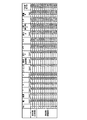
この鋼製床板1の各部の寸法例を図2と図6に示した。即ち、スリット1bの縦幅をa、隣接するスリット間の横桟1cの縦幅b、縦桟1aの横幅をc(図2参照)、スリットの横長をd(図2参照)、縦桟1aのせい(高さ)をH(図6B参照)、鋼板の板厚t、幅寸法をB(図2参照)、長さをL(図5)として、この鋼製床板1に図5Aの態様で鉛直荷重F(981N)を載荷した際に生じる鋼製床板1の中央部断面の肩部変位量δをFEM解析により求めた値を図4に表として示した。
Examples of the present invention will be described below.
In FIG. 1 and FIG. 5A, slits 1b having the same shape and the same pitch are formed alternately with the
The example of the dimension of each part of this
FEM解析の解析条件を図5に示したとおり、長さLが1400mm、脚部(縦桟)1aの底面幅e(図6C)が25mm、同せいの高さHが40mm(図6B)、その他の諸元は図4の表に示した通りの条件で設定した鋼製床板を、図5Aのように長手方向の両端を支持し、同鋼製床板の中央部に鉛直荷重F=981Nを載荷すると想定している。
同形状は、長さ方向、幅方向ともに対称な形状であるため、図5Bに示すように、想定形状の1/4の部分を対称境界条件を用いてシエル要素でモデル化しており、鉛直荷重F=981Nの1/4の鉛直荷重245.25Nとしている。
この解析モデルにおいて、ヤング係数を205000N/mm2、ポアソン比を0.3として、弾性解析を行った。
なお、従来例の幅寸は200mm又は250mm、板厚1.6mmとなっている。一方、本発明の実施例の幅寸は300mm、板厚は1.4mmとなっている。
As shown in FIG. 5 for the analysis conditions of the FEM analysis, the length L is 1400 mm, the bottom width e (FIG. 6C) of the leg portion (vertical beam) 1a is 25 mm, and the height H of the same is 40 mm (FIG. 6B). The other specifications are the steel floor plate set under the conditions shown in the table of FIG. 4, supporting both ends in the longitudinal direction as shown in FIG. 5A, and the vertical load F = 981N applied to the center of the steel floor plate. It is assumed that it will be loaded.
Since this shape is symmetrical in both the length and width directions, as shown in FIG. 5B, a quarter of the assumed shape is modeled with a shell element using a symmetrical boundary condition, and the vertical load The vertical load is 245.25N, which is 1/4 of F = 981N.
In this analysis model, elastic analysis was performed with a Young's modulus of 205000 N /
The width of the conventional example is 200 mm or 250 mm, and the plate thickness is 1.6 mm. On the other hand, the width dimension of the Example of this invention is 300 mm, and plate | board thickness is 1.4 mm.
図7に、鋼製床板のスリットの縦横幅比を縦軸とし、同スリットの縦幅と横桟の縦幅の比を横軸とした座標上に計算結果を示した。図7に記載した○印は、本発明に係る鋼製床板の実施例を示し、同○印に付記した数字は図4の表に記載した本発明の実施例の番号である。同じ図7に記載した×印は、比較例を示し、同×印に付記した数字は図4の表に記載した比較例の番号を示している。 FIG. 7 shows the calculation results on the coordinates where the vertical / horizontal ratio of the slit of the steel floor board is the vertical axis and the ratio of the vertical width of the slit to the vertical width of the horizontal rail is the horizontal axis. The circles shown in FIG. 7 indicate examples of the steel floor board according to the present invention, and the numbers added to the circles are the numbers of the examples of the present invention described in the table of FIG. The same X mark shown in FIG. 7 indicates a comparative example, and the number added to the X mark indicates the number of the comparative example described in the table of FIG.
図7の図表によれば、本発明の実施品である鋼製床板である○印9と○印10を結んだ直線(破線)は、a/d=0.077×(a/b)+0.017と表され、(a/d)>0.077×(a/b)+0.017を満たす領域(条件)の場合は、×印1〜×印3のようなスリット形状(図3Bの比較例No.1〜No.3を参照)となり、横桟1cがスリット形状と比較してあまり細長くない(スリットの縦幅と横桟の縦幅が同程度である)ことから、鋼製床板の意匠的美観(外観のすっきりさ)が改善されていないと判断される。
According to the chart of FIG. 7, the straight line (broken line) connecting the ◯
一方、a/d≦0.077×(a/b)+0.017の式を満たす領域の場合は、図7中の○印2、○印9及び○印10に示すスリット形状(図3Aの実施例No.2、No.9、No.10)の場合は、横桟1cがスリット形状と比較して細長くなっており、鋼製床板の意匠的美観(外観のすっきりさ)が改善されていることを理解されるであろう。
On the other hand, in the case of a region satisfying the expression of a / d ≦ 0.077 × (a / b) +0.017, the slit shapes shown in the
更に、図7において、本発明の実施品である○印5と○印7を結んだ直線は、a/d=0.077×(a/b)+0.001の式で表され、a/d≦0.077×(a/b)+0.001の式を満たす領域の場合は、図7中の○印2、○印5、○印7に示すスリット形状(図3Aの実施例No.2、No.5、No.7)の場合は、横桟1cがスリット1bの形状と比較して細長くなっており、鋼製床板の意匠的美観(外観のすっきりさ)が更に改善されることを理解されるであろう。
Further, in FIG. 7, the straight line connecting the
また、a/d≦0.145を満たす領域(条件)を本発明の必須不可欠の構成要件としているが、これはa/d値が大きいほど、鋼製床板のスリットが大きく見えて、見た目の開放感を感得させる効果がある。一方で、a/d値が0.145よりも大きくなった場合、スリットの縦幅aが大きくなりすぎて、施工時のドライバー等の工具の握りの外径寸法(太さ)よりも広幅になって、工具を不用意に落とした場合に、鋼製床板のスリットを通り抜けてしまい、事故の原因となる危険性がある。そのためドライバー等の工具類の落下事故を防ぐべく、ドライバー等の工具の握り部の外径寸法よりは幅狭のスリット幅を考慮した上限を設定したものである。更に、スリットの幅が大きくなりすぎると、歩行者が下を見下ろした場合に恐怖感を覚えるので、その限界を考慮して上限を設定したものである。 Moreover, although the area | region (condition) which satisfy | fills a / d <= 0.145 is made into the indispensable structural requirement of this invention, this is because the slit of a steel floor board appears large, so that the a / d value is large, and it looks There is an effect to feel openness. On the other hand, when the a / d value is larger than 0.145, the vertical width a of the slit becomes too large, and is wider than the outer diameter (thickness) of the grip of a tool such as a screwdriver during construction. Therefore, if the tool is dropped carelessly, it will pass through the slits in the steel floor board, which may cause an accident. Therefore, in order to prevent the accident of dropping of tools such as a screwdriver, an upper limit is set in consideration of a narrow slit width rather than the outer diameter of the grip portion of a tool such as a screwdriver. Furthermore, if the width of the slit becomes too large, when the pedestrian looks down, he / she feels fear, so the upper limit is set in consideration of the limit.
例えばスリットの縦幅a=35mmは、施工時にドライバー等の工具の握りの外径寸法(太さ)よりは小さく設定し、同工具類の落下を防ぐ条件にしている。また、スリットの縦幅aが35mmより広いと、歩行者が下を見下ろした場合に恐怖感を覚えるので、その限界を考慮して、本発明例のスリットの横幅dの最小値である240mm(図4の表を参照)の場合に、スリットの縦幅dを35mm以下に設定するため、a/d≦0.145を本発明の技術的範囲としている。 For example, the vertical width a = 35 mm of the slit is set to be smaller than the outer diameter (thickness) of the grip of a tool such as a driver at the time of construction so as to prevent the tool from dropping. In addition, if the vertical width a of the slit is larger than 35 mm, the pedestrian feels a sense of fear when looking down. Therefore, considering the limitation, 240 mm (the minimum value of the horizontal width d of the slit of the present invention) In the case of FIG. 4), a / d ≦ 0.145 is set as the technical scope of the present invention in order to set the vertical width d of the slit to 35 mm or less.
次に、図8は、上記した鋼製床板の中央部に鉛直荷重981Nを載荷したときの長手方向中央部の肩部変位量δ(図5Cを参照)を縦軸とし、上面開口率Pを横軸とした計算結果を示している。図8中に記載した○印は、本発明に係る鋼製床板の実施例の番号である。同じく図8に記載した×印は比較例を示し、同×印に付記した数字は図4の表に記載した比較例の番号である。
Next, in FIG. 8, the vertical axis is the shoulder displacement amount δ (see FIG. 5C) of the central portion in the longitudinal direction when the
なお、図9に示したように、鋼製床板の上面開口率Pの算出は、1モジュールにおける開口の面積(Aw)/1モジュールの水平投影面積積(Aa)と定義して算定する。1モジュールにおける開口の面積(Aw)は、上記図9に記載した各符号を用いると、(d−a)×a+(a×0.5)2×πとして求める。1モジュールの水平投影面積(Aa)は、B×(a+b)と定義する。 In addition, as shown in FIG. 9, calculation of the upper surface opening ratio P of a steel floor board is defined as the area of the opening in one module (Aw) / 1 horizontal projection area product of one module (Aa). The area (Aw) of the opening in one module is obtained as (d−a) × a + (a × 0.5) 2 × π using the symbols shown in FIG. The horizontal projection area (Aa) of one module is defined as B × (a + b).
図8によれば、本発明の実施例の鋼製床板を示す○印1の上面開口率Pは0.426である。一方、従来の鋼製床板を示す×印1の上面開口率Pは0.411である。
本発明は、上面開口率Pをできるだけ大きく構成することで、鋼製床板の外観がスッキリとして、鋼製床板の意匠的美観(外観のすっきりさ)を向上させるものである。
したがって、上記の式(イ):P≧0.426を、本発明の必須事項とした。
According to FIG. 8, the upper surface opening ratio P of ○
In the present invention, the upper surface opening ratio P is configured to be as large as possible, so that the appearance of the steel floor board is refreshed and the design aesthetics (the cleanliness of the external appearance) of the steel floor board is improved.
Therefore, the above formula (A): P ≧ 0.426 is an essential matter of the present invention.
図8には、図5Aに示す載荷状態に生じる鋼製床板の長手方向中央部の肩部変位量δの制限値をδ<4.67mmと示している。
これは鋼製床板で構築された場合、その床上歩行時における鋼製床板の撓み量(本願における肩部変位量δに相当する量)が制限値を超えると、通行人に恐怖感を感じさせることを意味する。例えば鋼構造設計基準(2002年第3版)の「第10章 たわみ」によれば、通行人に恐怖感を感じさせないためには、鋼製床板のスパンLの1/300以下に保つことが適当とされている。その故に、床板へ乗った人や物の重量に起因する撓み量の設計基準の検討が行われる。
FIG. 8 shows that the limit value of the shoulder displacement amount δ at the center portion in the longitudinal direction of the steel floor plate generated in the loaded state shown in FIG. 5A is δ <4.67 mm.
When this is constructed with a steel floorboard, if the amount of deflection of the steel floorboard when walking on the floor (the amount corresponding to the shoulder displacement amount δ in the present application) exceeds the limit value, the passerby feels a sense of fear. Means that. For example, according to “
このことは鋼製床板で床の意匠的美観(外観のすっきり感)の向上、及び鋼製床板の軽量化を目的として、上面開口率Pをできるだけ大きく設計すると、歩行時の床板の撓み量が問題になることを意味する。よって、歩行時の床板の撓み量を制限することを目的に、上面開口率Pをできるだけ小さく設計、施工すると、鋼製床板の意匠的美観(外観のすっきりさ)を損なうという問題が生ずることになり、単純に上面開口率Pの条件のみを検討する、安易な解決策を採用することは適切でない。 For the purpose of improving the design aesthetics of the floor (cleanness of the appearance) and reducing the weight of the steel floorboard with a steel floorboard, the amount of deflection of the floorboard during walking is reduced if the upper surface area ratio P is designed as large as possible. It means that it becomes a problem. Therefore, if the upper surface opening ratio P is designed and constructed as small as possible for the purpose of limiting the amount of bending of the floor board during walking, there arises a problem that the design aesthetics (the cleanliness of the appearance) of the steel floor board is impaired. Therefore, it is not appropriate to adopt an easy solution that simply considers only the condition of the upper surface opening ratio P.
従って、本発明による鋼製床板が、図5に示す載荷状態で生ずる鋼製床板の長手方向中央部の肩部変位量δをL/300以下とする制限値を満たしているかを確認している。そのため本発明のより好ましい実施条件としては、肩部変位量δの制限値を満たすとしても良いが、これに特に限定されない。 Therefore, it is confirmed whether the steel floor board according to the present invention satisfies the limit value for setting the shoulder displacement amount δ at the center part in the longitudinal direction of the steel floor board generated in the loaded state shown in FIG. 5 to L / 300 or less. . Therefore, a more preferable implementation condition of the present invention may satisfy the limit value of the shoulder displacement amount δ, but is not particularly limited thereto.
次に、図10は、鋼製床板のスパン中央部の肩部変位量δ(図5参照)と、上面開口率Pとの比を縦軸にとり、比較例No.1との重量比率W/W0を横軸にとった計算結果を示している。
図10に記載した○印は、本発明に係る鋼製床板の実施例を示し、同○印に付記した数字は図4の表に記載した本発明の実施例の番号である。同じ図10に記載した×印は比較例を示し、同×印に付記した数字は図4の表に記載した比較例の番号である。図10では、×印1が従来の鋼製床板の例として比較対象とし、符号W0は×印1の重量を示している。
Next, FIG. 10 shows the ratio of the shoulder displacement amount δ (see FIG. 5) at the center of the span of the steel floor board to the upper surface opening ratio P on the vertical axis, and the weight ratio W / with the comparative example No. 1 The calculation results with W0 on the horizontal axis are shown.
The circles shown in FIG. 10 indicate examples of the steel floor board according to the present invention, and the numbers added to the circles are the numbers of the examples of the present invention described in the table of FIG. The X mark shown in FIG. 10 indicates a comparative example, and the numbers added to the X mark are the numbers of the comparative examples described in the table of FIG. In FIG. 10, the
なお×印2は×印1よりも単位重量が重い。また、×印3は、幅寸Bが本発明の実施品に比べて極端に狭い。そのため、従来の鋼製床板に比して軽量化できているかを比較するためには、×印1が適当と判断され、軽量化の指標として、重量比率W/W0を採用している。
Note that the unit weight of the
図10によれば、本発明に係る鋼製床板である○印の全てが、重量比率W/W0の値が1未満となっている。これは従来の鋼製床板に比べて、軽量化出来ていることを意味している。
従って、上記の式イ、ロ、ハで特定した条件、又は上記の式イ、ロ、ニで特定した条件をそれぞれ満たす鋼製床板は、横桟1cがスリット形状と比較して細長くなっており、鋼製床板の意匠的美観(外観のすっきりさ)が従来品より改善され、かつ、鋼製床板の重量が従来の鋼製床板重量よりも軽量な構成になっている。
According to FIG. 10, the value of the weight ratio W / W0 is less than 1 for all the circles that are steel floor boards according to the present invention. This means that it is lighter than conventional steel floorboards.
Therefore, in the steel floor board that satisfies the conditions specified by the above formulas (i), (b), (c), or the conditions specified by the above formulas (a), (b), (d), the
なお、図4の表によって、鋼製床板の幅寸法Bを従来品よりも大きく、かつ、上面開口率Pを従来品よりも大きく構成して意匠的美観(外観のすっきりさ)を保持しつつ、従来品よりも軽量化された鋼製床板を提供するために、幅寸Bは300mm以上〜350mmまで、板厚tは1.4mm以下〜1.2mmまでが望ましいことが明らかである。
なお、本発明に係る鋼製床板の適用範囲は、鋼製床板の幅寸Bは150mm〜350mm、長さLが1000mm〜4000mmの範囲が実施可能であり、人力で運搬可能な重量と大きさと考えられる。
In addition, according to the table of FIG. 4, the width dimension B of the steel floor board is made larger than that of the conventional product, and the upper surface opening ratio P is made larger than that of the conventional product, while maintaining the design aesthetics (the clean appearance). In order to provide a steel floor plate that is lighter than conventional products, it is apparent that the width B is preferably 300 mm to 350 mm and the plate thickness t is 1.4 mm to 1.2 mm.
In addition, the applicable range of the steel floorboard according to the present invention is such that the width B of the steel floorboard is 150 mm to 350 mm, and the length L is 1000 mm to 4000 mm. Conceivable.
以上に本発明を実施例に基づいて説明したが、本発明の技術的思想は上記の限りではない。いわゆる当業者が必要に応じて行う設計変更や応用変形の範囲にまで及ぶものであることを念のために申し添える。 Although the present invention has been described above based on the embodiments, the technical idea of the present invention is not limited to the above. I would like to remind you that it extends to the range of design changes and application modifications that are made by those skilled in the art as needed.
1 鋼製床板
1b スリット
P 開口率
d スリットの横幅
1c 横桟
a スリットの縦幅
b 横桟の縦幅
1
Claims (3)
P≧0.426・・・・・・・・・・・・・・・・・・・(イ)
(a/d)≦ 0.145・・・・・・・・・・・・・・(ロ)
(a/d)<0.077×(a/b)+0.017・・・(ハ) Regarding the dimensional specification of each part of the steel floor plate with slits of the same size and the same pitch on the upper surface, the opening ratio of the upper surface is P, the vertical width of the slit is a, the horizontal length of the slit is d, the adjacent slit A steel floor board characterized by having a configuration satisfying the following formulas (A) to (C) when the vertical width of the horizontal rail is b:
P ≧ 0.426 ・ ・ ・ ・ ・ ・ ・ ・ ・ ・ ・ ・ ・ ・ ・ ・ (I)
(A / d) ≤ 0.145 (b)
(A / d) <0.077 × (a / b) +0.017 (C)
P≧0.426・・・・・・・・・・・・・・・・・・・(イ)
(a/d)≦ 0.145・・・・・・・・・・・・・・(ロ)
(a/d)<0.077×(a/b)+0.001・・・(ニ) Regarding the dimensional specification of each part of the steel floor plate with slits of the same size and the same pitch on the upper surface, the opening ratio of the upper surface is P, the vertical width of the slit is a, the horizontal length of the slit is d, the adjacent slit A steel floor board characterized by having a configuration that satisfies the following formulas (A), (B), and (D) when the vertical width of the horizontal rail is b:
P ≧ 0.426 ・ ・ ・ ・ ・ ・ ・ ・ ・ ・ ・ ・ ・ ・ ・ ・ (I)
(A / d) ≤ 0.145 (b)
(A / d) <0.077 × (a / b) +0.001 (D)
Priority Applications (1)
| Application Number | Priority Date | Filing Date | Title |
|---|---|---|---|
| JP2015101695A JP2016216977A (en) | 2015-05-19 | 2015-05-19 | Steel floorboard |
Applications Claiming Priority (1)
| Application Number | Priority Date | Filing Date | Title |
|---|---|---|---|
| JP2015101695A JP2016216977A (en) | 2015-05-19 | 2015-05-19 | Steel floorboard |
Publications (1)
| Publication Number | Publication Date |
|---|---|
| JP2016216977A true JP2016216977A (en) | 2016-12-22 |
Family
ID=57580390
Family Applications (1)
| Application Number | Title | Priority Date | Filing Date |
|---|---|---|---|
| JP2015101695A Pending JP2016216977A (en) | 2015-05-19 | 2015-05-19 | Steel floorboard |
Country Status (1)
| Country | Link |
|---|---|
| JP (1) | JP2016216977A (en) |
Citations (11)
| Publication number | Priority date | Publication date | Assignee | Title |
|---|---|---|---|---|
| JPS4615171Y1 (en) * | 1966-01-25 | 1971-05-27 | ||
| US4198795A (en) * | 1978-05-15 | 1980-04-22 | Barnidge, Inc. | Stainless steel flooring |
| JPH0253414U (en) * | 1988-10-12 | 1990-04-18 | ||
| JPH0640193U (en) * | 1992-10-27 | 1994-05-27 | 株式会社神戸製鋼所 | Translucent scaffolding board |
| JPH0972073A (en) * | 1995-09-05 | 1997-03-18 | Shiyouden:Kk | Floor panel |
| JPH10338963A (en) * | 1997-06-10 | 1998-12-22 | Nippon Light Metal Co Ltd | Floor slab |
| JP2000179149A (en) * | 1998-12-17 | 2000-06-27 | Shinko Noosu Kk | Cloth frame with floor |
| JP2002256696A (en) * | 2001-03-02 | 2002-09-11 | Hamana Works:Kk | Floor plate material having anti-skid function, and method for producing the same |
| JP2005111543A (en) * | 2003-10-09 | 2005-04-28 | Horii Engineering Kk | Perforated floor board and its manufacturing method, scaffolding board and work scaffolding stand using perforated floor board, die and press which are used for method of manufacturing perforated floor board |
| JP2008240490A (en) * | 2007-03-29 | 2008-10-09 | Hitachi Metals Techno Ltd | Panel fixing metal fitting and panel fixing method |
| JP2009030415A (en) * | 2007-07-30 | 2009-02-12 | Nikken Build:Kk | Floor structure using steel floor panel |
-
2015
- 2015-05-19 JP JP2015101695A patent/JP2016216977A/en active Pending
Patent Citations (11)
| Publication number | Priority date | Publication date | Assignee | Title |
|---|---|---|---|---|
| JPS4615171Y1 (en) * | 1966-01-25 | 1971-05-27 | ||
| US4198795A (en) * | 1978-05-15 | 1980-04-22 | Barnidge, Inc. | Stainless steel flooring |
| JPH0253414U (en) * | 1988-10-12 | 1990-04-18 | ||
| JPH0640193U (en) * | 1992-10-27 | 1994-05-27 | 株式会社神戸製鋼所 | Translucent scaffolding board |
| JPH0972073A (en) * | 1995-09-05 | 1997-03-18 | Shiyouden:Kk | Floor panel |
| JPH10338963A (en) * | 1997-06-10 | 1998-12-22 | Nippon Light Metal Co Ltd | Floor slab |
| JP2000179149A (en) * | 1998-12-17 | 2000-06-27 | Shinko Noosu Kk | Cloth frame with floor |
| JP2002256696A (en) * | 2001-03-02 | 2002-09-11 | Hamana Works:Kk | Floor plate material having anti-skid function, and method for producing the same |
| JP2005111543A (en) * | 2003-10-09 | 2005-04-28 | Horii Engineering Kk | Perforated floor board and its manufacturing method, scaffolding board and work scaffolding stand using perforated floor board, die and press which are used for method of manufacturing perforated floor board |
| JP2008240490A (en) * | 2007-03-29 | 2008-10-09 | Hitachi Metals Techno Ltd | Panel fixing metal fitting and panel fixing method |
| JP2009030415A (en) * | 2007-07-30 | 2009-02-12 | Nikken Build:Kk | Floor structure using steel floor panel |
Similar Documents
| Publication | Publication Date | Title |
|---|---|---|
| JP5449467B2 (en) | Passenger conveyor | |
| JP6362997B2 (en) | Renewal method of passenger conveyor | |
| US20130212960A1 (en) | Modules for converting a stairway | |
| JP5614812B2 (en) | Staircase | |
| JP2016216977A (en) | Steel floorboard | |
| JP5253234B2 (en) | Elevator car ceiling baseboard equipment | |
| JP4704291B2 (en) | Open staircase unit with landing | |
| JP6507052B2 (en) | Unit building structure | |
| JP2008175016A (en) | Horizontal grating body | |
| JP4937504B2 (en) | Building | |
| JP2018168574A (en) | Building unit and unit type building | |
| GB1596084A (en) | Slip-resistant walk-way members | |
| JP3732846B2 (en) | Open stair unit | |
| KR101187982B1 (en) | Safety footing for a work | |
| JP6650416B2 (en) | Passenger conveyor and passenger conveyor renewal method | |
| JP5288845B2 (en) | Building structure | |
| JP3134046U (en) | Portable worktable | |
| JP2015024907A (en) | Handrail panel of passenger conveyor and passenger conveyor | |
| JP5385170B2 (en) | Building frame structure | |
| JP7361629B2 (en) | staircase structure | |
| JP2013189832A (en) | Crossing stairway and connecting member for crossing stairway passage | |
| JP6573132B2 (en) | Exterior wall structure | |
| JP4222224B2 (en) | Structural frame | |
| JP6769667B2 (en) | Structure | |
| JP3162943U (en) | Scaffolding stairs |
Legal Events
| Date | Code | Title | Description |
|---|---|---|---|
| A621 | Written request for application examination |
Free format text: JAPANESE INTERMEDIATE CODE: A621 Effective date: 20180416 |
|
| A977 | Report on retrieval |
Free format text: JAPANESE INTERMEDIATE CODE: A971007 Effective date: 20190227 |
|
| A131 | Notification of reasons for refusal |
Free format text: JAPANESE INTERMEDIATE CODE: A131 Effective date: 20190305 |
|
| A601 | Written request for extension of time |
Free format text: JAPANESE INTERMEDIATE CODE: A601 Effective date: 20190423 |
|
| A521 | Request for written amendment filed |
Free format text: JAPANESE INTERMEDIATE CODE: A523 Effective date: 20190618 |
|
| A02 | Decision of refusal |
Free format text: JAPANESE INTERMEDIATE CODE: A02 Effective date: 20191203 |