JP2016215958A - Multicopter and multicopter system - Google Patents
Multicopter and multicopter system Download PDFInfo
- Publication number
- JP2016215958A JP2016215958A JP2015106039A JP2015106039A JP2016215958A JP 2016215958 A JP2016215958 A JP 2016215958A JP 2015106039 A JP2015106039 A JP 2015106039A JP 2015106039 A JP2015106039 A JP 2015106039A JP 2016215958 A JP2016215958 A JP 2016215958A
- Authority
- JP
- Japan
- Prior art keywords
- axis
- multicopter
- aircraft
- controlling
- gyro
- Prior art date
- Legal status (The legal status is an assumption and is not a legal conclusion. Google has not performed a legal analysis and makes no representation as to the accuracy of the status listed.)
- Pending
Links
Images


Abstract
Description
本発明は3軸ジャイロを利用したマルチコプター及びマルチコプターシステムに関し、特に複数の制御モードに特徴を有するマルチコプター及びマルチコプターシステムに関するものである。 The present invention relates to a multicopter and a multicopter system using a three-axis gyro, and more particularly to a multicopter and a multicopter system characterized by a plurality of control modes.
近年特許文献1に示されているように、複数個のロータを備え、空中で静止することができるマルチコプターが空撮用等に急速に普及しつつある。マルチコプターでは重心の周囲に複数のロータを配置し、その出力を制御することによって機体の上昇、下降、移動や静止を行っている。マルチコプターでは機体の動作を安定化させるため3軸のジャイロが用いられている。これらのジャイロは機体のロール軸回りの回転を検出するロール軸ジャイロ、機体のピッチ方向の回転を検出するピッチ軸ジャイロ、機体のヨー軸回りの回転を検出するヨー軸ジャイロが用いられている。3軸ロックモードでは、これらのジャイロからの出力に基づき、機体のロータ軸、ヨー軸及びピッチ軸の回転を停止させて空中で機体をホバリングさせるように制御している。
In recent years, as disclosed in
3軸ロックモードでは、各軸に対して外乱の影響を打ち消すようにモータをコントロールしているため、送信機からの操作が無ければ空中に容易に静止させることができる。従ってマルチコプターで空撮を行う場合には、3軸ロック制御が適している。 In the 3-axis lock mode, the motor is controlled so as to cancel the influence of disturbance on each axis, so that it can be easily stopped in the air if there is no operation from the transmitter. Therefore, when performing aerial photography with a multicopter, the 3-axis lock control is suitable.
しかし3軸ロックモードのままで飛行させる場合に、水平に旋回飛行させようとしても適切にラダーを操作しなければ進行方向と機首方向とが一致しなくなる。従ってマルチコプターが操縦者より少し離れただけで進行方向及び機首方向がわかりにくくなり、機体の操縦が極めて難しくなるという問題点があった。 However, when flying in the three-axis lock mode, the advancing direction and the nose direction will not match if the ladder is not operated properly even if the flight is to be performed horizontally. Therefore, there is a problem in that the traveling direction and the nose direction are difficult to understand even if the multicopter is slightly away from the pilot, and it is very difficult to control the aircraft.
本発明は機体の操縦モードを切換えることによって進行させる場合にもラダー軸の操作を容易にし、機体を操縦できるようにすることを目的とする。 An object of the present invention is to facilitate the operation of a rudder shaft even when advancing by switching the control mode of the aircraft, and to make it possible to control the aircraft.
この課題を解決するために、本発明のマルチコプターは、機体の重心を通る中心から所定距離離れた位置に配置された複数のロータユニットと、前記機体の重心から隔てた位置に設けられ、ヨー軸方向に空力的に風見鶏効果をもたらす尾翼と、前記機体の3軸方向の回転角速度を夫々検出するロール軸ジャイロ、ピッチ軸ジャイロ、ヨー軸ジャイロと、複数のロータユニットの各出力を制御することによって機体の3軸方向のコントロール及びパワーコントロールを行うコントローラと、を具備するものであり、前記コントローラは、前記レートジャイロからの信号によりヨー軸、ロール軸、ピッチ軸の外乱による角度変化を復帰させるように各ロータユニットを制御するロックモードと、前記ロール軸及びピッチ軸による外乱による角度変化を復帰させ、ヨー軸の外乱による角度変化を減衰させるように前記各ロータユニットを制御するダンピングモードと、を有するものである。 In order to solve this problem, the multicopter of the present invention is provided with a plurality of rotor units arranged at a predetermined distance from the center passing through the center of gravity of the aircraft, and at a position separated from the center of gravity of the aircraft. Controlling each output of a plurality of rotor units, a tail wing that provides an aerodynamic windcock effect in the axial direction, a roll axis gyro, a pitch axis gyro, and a yaw axis gyro that detect rotational angular velocities in the three axis directions of the aircraft, respectively. And a controller for controlling the power in three directions of the aircraft and power control, and the controller restores the angle change due to disturbance of the yaw axis, roll axis, and pitch axis by a signal from the rate gyro. In this way, the lock mode for controlling each rotor unit and the angle change due to disturbance by the roll axis and the pitch axis To return the those having a damping mode said controlling each rotor unit to damp angular change due to disturbance yaw axis.
ここで前記尾翼は、垂直尾翼、V字形尾翼、十字形尾翼、箱形尾翼、X字形尾翼のいずれか1つとしてもよい。 Here, the tail may be any one of a vertical tail, a V-shaped tail, a cross-shaped tail, a box-shaped tail, and an X-shaped tail.
この課題を解決するために、本発明のマルチコプターは、機体の重心を通る中心から所定距離離れた位置に配置された複数のロータユニットと、前記機体の重心から隔てた位置に設けられ、ヨー軸方向に空力的に風見鶏効果をもたらす抵抗体と、前記機体の3軸方向の回転角速度を夫々検出するロール軸ジャイロ、ピッチ軸ジャイロ、ヨー軸ジャイロと、複数のロータユニットの各出力を制御することによって機体の3軸方向のコントロール及びパワーコントロールを行うコントローラと、を具備するものであり、前記コントローラは、前記レートジャイロからの信号によりヨー軸、ロール軸、ピッチ軸の外乱による角度変化を復帰させるように各ロータユニットを制御するロックモードと、前記ロール軸及びピッチ軸による外乱による角度変化を復帰させ、ヨー軸の外乱による角度変化を減衰させるように前記各ロータユニットを制御するダンピングモードと、を有するものである。 In order to solve this problem, the multicopter of the present invention is provided with a plurality of rotor units arranged at a predetermined distance from the center passing through the center of gravity of the aircraft, and at a position separated from the center of gravity of the aircraft. Control each output of a plurality of rotor units, a resistor that aerodynamically provides a weathercock effect in the axial direction, a roll axis gyro, a pitch axis gyro, and a yaw axis gyro that detect the rotational angular velocities in the three axial directions of the aircraft. And a controller for controlling the power in three axes of the airframe and power control, and the controller recovers the angle change due to disturbance of the yaw axis, roll axis, and pitch axis by a signal from the rate gyro. A lock mode for controlling each rotor unit so as to cause an angle caused by disturbance by the roll axis and the pitch axis Reduction to return the those having a damping mode said controlling each rotor unit to damp angular change due to disturbance yaw axis.
ここで前記抵抗体は、尻尾及び抵抗板のいずれかとしてもよい。 Here, the resistor may be either a tail or a resistor plate.
この課題を解決するために、本発明のマルチコプターシステムは、マルチコプターと前記マルチコプターを制御する送信機とを有するマルチコプターシステムであって、前記送信機は、前記ロックモード及びダンピングモードを切換えるモードスイッチを有するものであり、前記マルチコプターは、前述に記載のマルチコプターとしてもよい。 In order to solve this problem, the multicopter system of the present invention is a multicopter system including a multicopter and a transmitter that controls the multicopter, and the transmitter switches between the lock mode and the damping mode. It has a mode switch, and the multicopter may be the multicopter described above.
このような特徴を有する本発明によれば、マルチコプターを3軸ロックモードとダンピングモードとに切換えることができる。3軸ロックモードでは従来の制御と同様に、外乱の影響をなくして機体を操作し、特に空中に静止させることが容易となる。又機体を通常の飛行機のように前進を基本として飛行させる場合に、垂直尾翼によってヨー軸の安定性を維持することができる。そしてヨー軸をダンピングモードとして制御することによって機体の進行方向と機首方向のずれをなくすことができ、容易に飛行させることができるという効果が得られる。 According to the present invention having such characteristics, the multicopter can be switched between the three-axis lock mode and the damping mode. In the three-axis lock mode, as in the conventional control, it is easy to operate the aircraft without disturbing the influence of the disturbance, and to stand still in the air. Also, when the aircraft flies on the basis of forward movement like a normal airplane, the stability of the yaw axis can be maintained by the vertical tail. By controlling the yaw axis as a damping mode, it is possible to eliminate the deviation between the advancing direction and the nose direction of the aircraft, and to obtain an effect of being able to fly easily.
図1は本発明の第1の実施の形態によるマルチコプターを示す斜視図であり、図2はその主要部を示す立面図である。図2に示すようにマルチコプター10はフレーム11の前方に一対のアーム12,13、後方に一対のアーム14,15が取付けられている。そして各アーム12〜15の先端にはモータ16〜19が設けられる。モータ16〜19には夫々上向きにロータ20〜23が取付けられている。
FIG. 1 is a perspective view showing a multicopter according to a first embodiment of the present invention, and FIG. 2 is an elevation view showing a main part thereof. As shown in FIG. 2, the
そしてフレーム11の上部には受信機24,ジャイロセンサ25及びコントローラ26とバッテリー27が設けられている。そして機体の上部には図1に示すようにカバー28が取付けられる。カバー28には図1に示すように機体後方に進行方向と平行な垂直尾翼29が設けられている。尚ジャイロセンサ25は機体のほぼ中央の重心付近に設けられている。又重心付近から所定距離離れた位置に対称にモータ及びロータが設けられる。モータ及びロータはロータユニットを構成している。
A
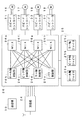
次にこの実施の形態によるマルチコプターの機能的な構成について図3のブロック図を用いて説明する。本図に示すようにマルチコプター10には受信機24,ジャイロセンサ25,コントローラ26が搭載されている。受信機24は送信機30からの信号を受信するものである。送信機30はピッチング制御、ラダー制御、ロール制御及びパワー制御の4チャンネルと、後述するようにヘッドロックモードの切換えに用いられる1チャンネルの5チャンネル以上の送信機とし、ロックモード及びダンピングモードを切換えるモードスイッチを有している。受信機24はこの信号を受信し、図示のように5チャンネル分の信号を夫々コントローラ26に出力する。これらの信号は並列で出力するものであってもよく、又シリアル信号として出力するものであってもよい。
Next, the functional configuration of the multicopter according to this embodiment will be described with reference to the block diagram of FIG. As shown in the figure, the
ジャイロセンサ25は3軸の回転角速度を検出するためのセンサである。ジャイロセンサ25はロール軸の回転角速度を検出するロール軸ジャイロ25a、ピッチ軸の回転角速度を検出するピッチ軸ジャイロ25b及びヨー軸の回転角速度を検出するヨー軸ジャイロ25cから成り立っており、ジャイロセンサ25の3軸の信号がコントローラ26に出力される。
The
コントローラ26の内部では受信機24からの各出力に基づいて出力制御を行うパワー制御部26a、ロール軸の制御を行うロール軸制御部26b、ピッチ軸の制御を行うピッチ軸制御部26c、ヨー軸の制御を行うヨー軸制御部26dを有している。夫々の出力はミキサ(MIX)26e,26f,26g,26hに出力される。ミキサ26e〜26hは各軸のモータ16,17,18,19に対する出力レベルを合成するものであり、その出力はスピードコントローラ31,32,33,34に与えられる。スピードコントローラ31〜34はアーム12〜15の先端に取付けられているモータ16〜19の出力を夫々制御するものである。
Inside the
尚ジャイロセンサ25には、前述した3軸方向の回転角速度を検知するジャイロ25a〜25cに加えて3軸方向の加速度センサや地磁気センサが取付けられることがあるが、本実施の形態とは直接関連がないので説明を省略する。
The
次に本実施の形態によるマルチコプターの制御について図4を用いて説明する。この実施の形態によるマルチコプターは、2つの制御モード、即ち3軸ロックモードとダンピングモードとを有している。動作を開始すると、まず受信機側で送信機30からの信号に基づいてロール軸,ピッチ軸,ヨー軸及び出力制御を通常通り行う(ステップS1)。そしてステップS2,S3,S4において、いずれかのジャイロセンサ25a,25b,25cからの信号があるかどうかをチェックする。そしてジャイロ25cからの信号があればステップS5においてダンピングモードであるかどうかを判別する。送信機30より設定されているモードがダンピングモードでなければ、3軸ロックモードであると判断する。第1の3軸ロックモードは通常のマルチコプターに従来から用いられている制御方法である。これは通常のヨー軸,ロール軸及びピッチ軸にロックモードでジャイロを働かせるものである(ステップS6〜S8)。ここでロックモードとは、角度の変化量、即ちずれた角度を0にするモードである。このモードでは、ずれた角度を0にすることによって外乱の影響で機体の姿勢が変化した場合であっても元の姿勢に復帰させることができる。この制御方法では機体に対する外乱を防いで飛行を安定させるため、送信機からの操作があれば各ロータを回転制御することで機体を操縦することができる。送信機からの操作がなければ外乱の影響を防ぐように自動的に各ロータの回転が制御できる。
Next, the control of the multicopter according to the present embodiment will be described with reference to FIG. The multicopter according to this embodiment has two control modes, that is, a three-axis lock mode and a damping mode. When the operation is started, first, the roll axis, pitch axis, yaw axis and output control are performed as usual on the receiver side based on the signal from the transmitter 30 (step S1). In steps S2, S3, and S4, it is checked whether there is a signal from any of the
次に第2のダンピングモードについて説明する。送信機30からの指令によってダンピングモードが設定されると、ヨー軸ジャイロ25cからの信号はダンピングモードによって制御する(ステップS9)。ダンピングモードとは、回転角速度を0にするように制御するモードである。このためヨー軸方向について外乱の影響を減衰させるように制御するが、一旦機体の姿勢が変化した場合には元の姿勢には復帰させず外乱の影響を減衰させるに留まる。ロール軸及びピッチ軸ジャイロについてはロックモードと同様に動作する(ステップS6,S7)。
Next, the second damping mode will be described. When the damping mode is set by a command from the
これにより機体を前方に進行させると、ヨー軸のダンピングモードでの制御と垂直尾翼の風見鶏効果によって機首が進行方向を向くこととなる。そのため機体を機首方向に向けて進行させる場合に機首の向きを容易に判断することができる。従って操縦者から機体までの距離が離れていてもラダー操作が容易で操縦し易く、通常の飛行機のように操縦することができる。そして空撮等で機体を静止させる場合には、再び3軸ロックモードとし、機体の速度を停止する。これによって機体を空中で静止させるなどの処理が可能となる。 As a result, when the aircraft is moved forward, the nose turns in the traveling direction due to the control in the damping mode of the yaw axis and the weathercock effect of the vertical tail. Therefore, the direction of the nose can be easily determined when the aircraft is advanced in the nose direction. Therefore, even if the distance from the pilot to the aircraft is large, the ladder operation is easy and the pilot can be easily operated, and the aircraft can be operated like a normal airplane. When the aircraft is to be stopped for aerial photography or the like, the 3-axis lock mode is set again, and the velocity of the aircraft is stopped. As a result, it is possible to perform processing such as stopping the aircraft in the air.
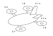
次に本発明の他の実施の形態について第1の実施の形態との相違点を中心として説明する。前述した実施の形態では垂直尾翼を用いて風見鶏効果を得るようにしているが、以下の実施の形態では垂直尾翼に代えて他の形状を採用したものである。まず第2の実施の形態では、図5に示すように垂直尾翼に代えて機体の重心位置より後方にV字形の尾翼41a,41bを左右対称に設けている。その他の構成は第1の実施の形態と同様である。 Next, another embodiment of the present invention will be described focusing on the differences from the first embodiment. In the above-described embodiment, the wind vane effect is obtained by using the vertical tail, but in the following embodiments, other shapes are adopted instead of the vertical tail. First, in the second embodiment, as shown in FIG. 5, V-shaped tails 41a and 41b are provided symmetrically on the rear side of the center of gravity of the airframe instead of the vertical tail. Other configurations are the same as those of the first embodiment.
次に第3の実施の形態では、図6に示すように機体の重心位置より後方に円筒形の筒状尾翼42を設け、これを垂直尾翼及び水平尾翼に代わるものとして用いている。この筒状尾翼42を円筒の軸が機体の進行方向と一致するように取付けることで、機体を進行させて風見鶏効果を得ることができる。 Next, in the third embodiment, as shown in FIG. 6, a cylindrical tubular tail 42 is provided behind the center of gravity of the airframe, and this is used as an alternative to the vertical and horizontal tails. By attaching this cylindrical tail wing 42 so that the axis of the cylinder coincides with the traveling direction of the aircraft, the aircraft can be advanced to obtain the weathercock effect.
次に第4の実施の形態では、図7に示すように機体の重心位置より後方に十字形尾翼43を取付けたものである。この十字形尾翼43の中心軸が機体の進行方向と一致するように取付けることで、機体を進行させて風見鶏効果を得ることができる。この変形例としてX字形の尾翼としてもよい。 Next, in the fourth embodiment, as shown in FIG. 7, a cruciform tail 43 is attached behind the center of gravity of the airframe. By attaching the cross-shaped tail wing 43 so that the central axis thereof coincides with the traveling direction of the aircraft, the aircraft can be advanced to obtain the weathercock effect. As this modification, an X-shaped tail may be used.
更に第5の実施の形態では、図8に示すように機体の重心位置より後方に箱形尾翼44を形成したものである。この場合も箱形尾翼44の中心軸を機体の進行方向と一致するように取付けることで、機体を進行させて風見鶏効果を得ることができる。 Further, in the fifth embodiment, as shown in FIG. 8, a box-shaped tail 44 is formed behind the center of gravity of the airframe. Also in this case, by attaching the central axis of the box-shaped tail 44 so as to coincide with the traveling direction of the aircraft, the aircraft can be advanced to obtain the weathercock effect.
次に第6の実施の形態では、図9に示すように胴体形状を無尾翼形に形成したものである。無尾翼形の胴体45の機体の場合には、機体の中心よりいずれか一方、例えば右翼が前方に、左翼が後方に下がって飛行すると、右翼は空気の抵抗が大きくなり、左翼は鋭角となって抵抗が小さくなる。左右逆の場合も同様であるため、均衡をとるように左右の翼が中心線より均衡になるように動き直進することとなる。従って無尾翼形であっても胴体45の形状が垂直尾翼に相当し、機体を進行させることで風見鶏効果を得ることができる。
Next, in the sixth embodiment, as shown in FIG. 9, the fuselage is formed into a tailless wing shape. In the case of an airfoil body with a
次に本発明のその他の実施の形態について説明する。前述した各実施の形態では風見鶏効果を得るために種々の形状の尾翼を用いているが、以下の実施の形態では尾翼に代えて抵抗体としたものである。第7の実施の形態では図10に示すように機体の後方に板状の柔軟な部材を設け、これを尻尾51としたものである。これにより機体が進行すると、尻尾51の抵抗を最小とする力が働く。即ち尻尾51の延長線上に機体が進行するときに尻尾51の抵抗が最小となるため、機体に対して風見鶏効果を与えることができる。 Next, other embodiments of the present invention will be described. In each of the embodiments described above, tails of various shapes are used in order to obtain the weathercock effect, but in the following embodiments, resistors are used instead of the tails. In the seventh embodiment, as shown in FIG. 10, a plate-like flexible member is provided at the rear of the machine body, and this is used as a tail 51. Thus, when the aircraft advances, a force that minimizes the resistance of the tail 51 works. That is, since the resistance of the tail 51 is minimized when the aircraft advances on the extension line of the tail 51, a weathercock effect can be given to the aircraft.
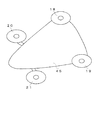
次に第8の実施の形態では、図11に示すように抵抗体として後方のアーム14,15にV字形の抵抗板52a,52bを前面が進行方向に向くように対称に配置したものである。こうすれば機体を前方に進行させるときには左右の抵抗板52a,52bに均一に抵抗が加わり、正常に前進することができる。そして機体が左右いずれかに傾くと、傾いた側の抵抗板の抵抗値が大きくなり他方の抵抗板の抵抗値が小さくなるため、機体の姿勢を元に戻すことができ、風見鶏効果を得ることができる。
Next, in the eighth embodiment, as shown in FIG. 11, V-shaped resistance plates 52a and 52b are arranged symmetrically on the
尚前述した第2〜第8の実施の形態においても図2,図3に示すブロック図の構成と動作は第1の実施の形態と同様である。これらの各実施の形態においても機体を前方に進行させると、ヨー軸のダンピングモードでの制御と尾翼等の風見鶏効果によって機首が進行方向を向くこととなる。そのため機体を機首方向に向けて進行させる場合に機首の向きを容易に判断することができる。従って操縦者から機体までの距離が離れていてもラダー操作が容易で操縦し易く、通常の飛行機のように操縦することができる。そして空撮等で機体を静止させる場合には、再び3軸ロックモードとし、機体の速度を停止する。これによって機体を空中で静止させるなどの処理が可能となる。 In the second to eighth embodiments described above, the configurations and operations of the block diagrams shown in FIGS. 2 and 3 are the same as those of the first embodiment. Also in each of these embodiments, when the aircraft is advanced forward, the nose turns in the traveling direction by the control in the damping mode of the yaw axis and the weathercock effect such as the tail. Therefore, the direction of the nose can be easily determined when the aircraft is advanced in the nose direction. Therefore, even if the distance from the pilot to the aircraft is large, the ladder operation is easy and the pilot can be easily operated, and the aircraft can be operated like a normal airplane. When the aircraft is to be stopped for aerial photography or the like, the 3-axis lock mode is set again, and the velocity of the aircraft is stopped. As a result, it is possible to perform processing such as stopping the aircraft in the air.
本発明は通常の空撮等に適した3軸ロックモードとラダー軸のみ外乱の影響を減衰させるダンピングモードとを切換えることによって通常の飛行を容易にし、機体を容易に飛行させ操縦を楽しむことができ、マルチコプターに広く用いることができる。 The present invention makes normal flight easier by switching between a three-axis lock mode suitable for normal aerial photography and the like and a damping mode that attenuates the influence of disturbance only on the ladder axis, and allows the aircraft to fly easily and enjoy maneuvering. Can be widely used in multicopters.
10 マルチコプター
11 フレーム
12〜15 アーム
16〜19 モータ
20〜23 ロータ
24 受信機
25 ジャイロセンサ
25a ロール軸ジャイロ
25b ピッチ軸ジャイロ
25c ヨー軸ジャイロ
26 コントローラ
26a パワー制御部
26b ロール軸制御部
26c ピッチ軸制御部
26d ヨー軸制御部
26e,26f,26g,26h ミキサ
30 送信機
31〜34 スピードコントローラ
41a,41b V字形尾翼
42 筒状尾翼
43 十字形尾翼
44 箱形尾翼
45 胴体
51 尻尾
52a,52b 抵抗板
DESCRIPTION OF
Claims (5)
前記機体の重心から隔てた位置に設けられ、ヨー軸方向に空力的に風見鶏効果をもたらす尾翼と、
前記機体の3軸方向の回転角速度を夫々検出するロール軸ジャイロ、ピッチ軸ジャイロ、ヨー軸ジャイロと、
複数のロータユニットの各出力を制御することによって機体の3軸方向のコントロール及びパワーコントロールを行うコントローラと、を具備するものであり、
前記コントローラは、
前記レートジャイロからの信号によりヨー軸、ロール軸、ピッチ軸の外乱による角度変化を復帰させるように各ロータユニットを制御するロックモードと、
前記ロール軸及びピッチ軸による外乱による角度変化を復帰させ、ヨー軸の外乱による角度変化を減衰させるように前記各ロータユニットを制御するダンピングモードと、を有するものであるマルチコプター。 A plurality of rotor units arranged at a predetermined distance from the center passing through the center of gravity of the aircraft,
A tail wing provided at a position separated from the center of gravity of the aircraft, and aerodynamically providing a weathercock effect in the yaw axis direction;
A roll axis gyro, a pitch axis gyro, and a yaw axis gyro that respectively detect rotational angular velocities in the three axis directions of the aircraft,
A controller for controlling the power in the three axial directions of the airframe and controlling the power by controlling the outputs of the plurality of rotor units,
The controller is
A lock mode for controlling each rotor unit so as to restore an angular change due to disturbance of the yaw axis, roll axis, and pitch axis by a signal from the rate gyro;
And a damping mode for controlling each of the rotor units so as to restore an angle change caused by disturbance caused by the roll axis and the pitch axis and to attenuate the angle change caused by the yaw axis disturbance.
前記機体の重心から隔てた位置に設けられ、ヨー軸方向に空力的に風見鶏効果をもたらす抵抗体と、
前記機体の3軸方向の回転角速度を夫々検出するロール軸ジャイロ、ピッチ軸ジャイロ、ヨー軸ジャイロと、
複数のロータユニットの各出力を制御することによって機体の3軸方向のコントロール及びパワーコントロールを行うコントローラと、を具備するものであり、
前記コントローラは、
前記レートジャイロからの信号によりヨー軸、ロール軸、ピッチ軸の外乱による角度変化を復帰させるように各ロータユニットを制御するロックモードと、
前記ロール軸及びピッチ軸による外乱による角度変化を復帰させ、ヨー軸の外乱による角度変化を減衰させるように前記各ロータユニットを制御するダンピングモードと、を有するものであるマルチコプター。 A plurality of rotor units arranged at a predetermined distance from the center passing through the center of gravity of the aircraft,
A resistor provided at a position separated from the center of gravity of the aircraft, and aerodynamically providing a weathercock effect in the yaw axis direction;
A roll axis gyro, a pitch axis gyro, and a yaw axis gyro that respectively detect rotational angular velocities in the three axis directions of the aircraft,
A controller for controlling the power in the three axial directions of the airframe and controlling the power by controlling the outputs of the plurality of rotor units,
The controller is
A lock mode for controlling each rotor unit so as to restore an angular change due to disturbance of the yaw axis, roll axis, and pitch axis by a signal from the rate gyro;
And a damping mode for controlling each of the rotor units so as to restore an angle change caused by disturbance caused by the roll axis and the pitch axis and to attenuate the angle change caused by the yaw axis disturbance.
前記送信機は、前記ロックモード及びダンピングモードを切換えるモードスイッチを有するものであり、
前記マルチコプターは、請求項1〜4のいずれか1項記載のマルチコプターであるマルチコプターシステム。 A multicopter system comprising a multicopter and a transmitter for controlling the multicopter,
The transmitter has a mode switch for switching between the lock mode and the damping mode,
The multicopter system according to claim 1, wherein the multicopter is a multicopter according to claim 1.
Priority Applications (1)
| Application Number | Priority Date | Filing Date | Title |
|---|---|---|---|
| JP2015106039A JP2016215958A (en) | 2015-05-26 | 2015-05-26 | Multicopter and multicopter system |
Applications Claiming Priority (1)
| Application Number | Priority Date | Filing Date | Title |
|---|---|---|---|
| JP2015106039A JP2016215958A (en) | 2015-05-26 | 2015-05-26 | Multicopter and multicopter system |
Publications (1)
| Publication Number | Publication Date |
|---|---|
| JP2016215958A true JP2016215958A (en) | 2016-12-22 |
Family
ID=57578192
Family Applications (1)
| Application Number | Title | Priority Date | Filing Date |
|---|---|---|---|
| JP2015106039A Pending JP2016215958A (en) | 2015-05-26 | 2015-05-26 | Multicopter and multicopter system |
Country Status (1)
| Country | Link |
|---|---|
| JP (1) | JP2016215958A (en) |
Cited By (5)
| Publication number | Priority date | Publication date | Assignee | Title |
|---|---|---|---|---|
| DE102018133171A1 (en) * | 2018-12-20 | 2020-06-25 | Universität Stuttgart | Aircraft |
| JP2020522428A (en) * | 2017-08-01 | 2020-07-30 | ▲広▼州▲極飛▼科技有限公司Guangzhou Xaircraft Technology Co., Ltd. | Drone |
| JP2020138671A (en) * | 2019-02-28 | 2020-09-03 | 富士通株式会社 | Flight machine and flight machine control method |
| WO2022193157A1 (en) * | 2021-03-16 | 2022-09-22 | 深圳市大疆创新科技有限公司 | Multi-rotor aerial vehicle |
| US11640178B2 (en) | 2016-12-13 | 2023-05-02 | Acsl Ltd. | Unmanned aircraft, device for controlling unmanned aircraft, method for controlling unmanned aircraft, and device for detecting failure of unmanned aircraft |
-
2015
- 2015-05-26 JP JP2015106039A patent/JP2016215958A/en active Pending
Cited By (7)
| Publication number | Priority date | Publication date | Assignee | Title |
|---|---|---|---|---|
| US11640178B2 (en) | 2016-12-13 | 2023-05-02 | Acsl Ltd. | Unmanned aircraft, device for controlling unmanned aircraft, method for controlling unmanned aircraft, and device for detecting failure of unmanned aircraft |
| JP2020522428A (en) * | 2017-08-01 | 2020-07-30 | ▲広▼州▲極飛▼科技有限公司Guangzhou Xaircraft Technology Co., Ltd. | Drone |
| DE102018133171A1 (en) * | 2018-12-20 | 2020-06-25 | Universität Stuttgart | Aircraft |
| US11697494B2 (en) | 2018-12-20 | 2023-07-11 | Volocopter Gmbh | Aircraft |
| JP2020138671A (en) * | 2019-02-28 | 2020-09-03 | 富士通株式会社 | Flight machine and flight machine control method |
| JP7180450B2 (en) | 2019-02-28 | 2022-11-30 | 富士通株式会社 | Aircraft and control method for aircraft |
| WO2022193157A1 (en) * | 2021-03-16 | 2022-09-22 | 深圳市大疆创新科技有限公司 | Multi-rotor aerial vehicle |
Similar Documents
| Publication | Publication Date | Title |
|---|---|---|
| Bapst et al. | Design and implementation of an unmanned tail-sitter | |
| AU2017252251B2 (en) | Wind finding and compensation for unmanned aircraft systems | |
| JP4984591B2 (en) | Automatic attitude control device, automatic attitude control method, and automatic attitude control program | |
| EP2673681B1 (en) | Flight control laws for constant vector flat turns | |
| US20170371352A1 (en) | Method for dynamically converting the attitude of a rotary-wing drone | |
| JP2016215958A (en) | Multicopter and multicopter system | |
| US20170217584A1 (en) | System and method of operation of twin-tiltrotor helicopter | |
| KR101118888B1 (en) | Systems and methods for controlling dynamic systems | |
| US20170364093A1 (en) | Drone comprising lift-producing wings | |
| TW381202B (en) | Moving body control device | |
| CN108594839B (en) | Control method, aircraft and storage medium based on more vectoring technologies | |
| CN106043695B (en) | A kind of dynamic multi-rotor unmanned aerial vehicle fixed pitch variable speed system of oil and control technology | |
| JP2004268730A (en) | Attitude control method for unmanned helicopter | |
| JP2009143268A (en) | Flight control system for aircraft and aircraft with the flight control system | |
| JP2009298287A (en) | Telescopic shaft flight stable flight machine | |
| US20220308597A1 (en) | System and method for tilt dead reckoning | |
| JP7185378B2 (en) | Arithmetic processing unit, radio-controlled aircraft | |
| KR101621461B1 (en) | Quad-Rotor position control system and control method thereof | |
| CN113200145B (en) | Portable micro coaxial double-propeller unmanned aerial vehicle and control method thereof | |
| KR102260716B1 (en) | Multicopter Yawing Control System | |
| US9283490B1 (en) | Device for stabilising a flying attitude of a remote-controlled fixed-wing aircraft | |
| JP3189025B2 (en) | Aircraft attitude control device | |
| Firsov et al. | Compact vertical take-off and landing aerial vehicle for monitoring tasks in dense urban areas | |
| JPH07257489A (en) | Attitude control device for flying body | |
| Pham et al. | Sensor signal filtering in quadrotor control |
Legal Events
| Date | Code | Title | Description |
|---|---|---|---|
| A711 | Notification of change in applicant |
Free format text: JAPANESE INTERMEDIATE CODE: A711 Effective date: 20180509 |
|
| A521 | Written amendment |
Free format text: JAPANESE INTERMEDIATE CODE: A821 Effective date: 20180509 |