JP2016212607A - Message display device, monitoring system, message display method and program - Google Patents
Message display device, monitoring system, message display method and program Download PDFInfo
- Publication number
- JP2016212607A JP2016212607A JP2015095372A JP2015095372A JP2016212607A JP 2016212607 A JP2016212607 A JP 2016212607A JP 2015095372 A JP2015095372 A JP 2015095372A JP 2015095372 A JP2015095372 A JP 2015095372A JP 2016212607 A JP2016212607 A JP 2016212607A
- Authority
- JP
- Japan
- Prior art keywords
- message
- displayed
- display area
- messages
- message display
- Prior art date
- Legal status (The legal status is an assumption and is not a legal conclusion. Google has not performed a legal analysis and makes no representation as to the accuracy of the status listed.)
- Granted
Links
- 238000012544 monitoring process Methods 0.000 title claims abstract description 83
- 238000000034 method Methods 0.000 title claims abstract description 60
- 238000012806 monitoring device Methods 0.000 abstract 1
- 238000003860 storage Methods 0.000 description 19
- 239000000872 buffer Substances 0.000 description 14
- 230000005540 biological transmission Effects 0.000 description 7
- 238000010586 diagram Methods 0.000 description 7
- 230000006870 function Effects 0.000 description 5
- XLYOFNOQVPJJNP-UHFFFAOYSA-N water Substances O XLYOFNOQVPJJNP-UHFFFAOYSA-N 0.000 description 5
- 238000012545 processing Methods 0.000 description 4
- 238000004891 communication Methods 0.000 description 3
- 238000004519 manufacturing process Methods 0.000 description 1
- 238000012986 modification Methods 0.000 description 1
- 230000004048 modification Effects 0.000 description 1
- 230000002093 peripheral effect Effects 0.000 description 1
- 238000010248 power generation Methods 0.000 description 1
- 238000003825 pressing Methods 0.000 description 1
- 239000000126 substance Substances 0.000 description 1
Images


Abstract
Description
本発明の実施形態は、メッセージ表示装置、監視システム、メッセージ表示方法及びプログラムに関する。 Embodiments described herein relate generally to a message display device, a monitoring system, a message display method, and a program.
一般的に、プラントの監視システムは、ユーザに対してプラントの状態を表示する装置であるHMI(ヒューマンマシーンインタフェース)を有する。HMIは、監視対象のプラントにおいて発生した機器の動作情報や、機器の故障を示すアラーム情報などを、履歴メッセージとして表示する。
通常、発生した履歴メッセージを確認する場合、ユーザは、履歴メッセージを参照するための専用の画面をHMIに表示させる。HMIは、その専用の画面内に、履歴メッセージを一覧形式で表示する。また、特定のHMIには、画面上に常時数件の最新のメッセージを表示するための領域を有するものもある。この領域の表示により、発生した履歴メッセージを、専用の画面を表示することなく確認することができる。
Generally, a plant monitoring system has an HMI (Human Machine Interface) which is a device that displays a plant state to a user. The HMI displays device operation information generated in the monitored plant, alarm information indicating a device failure, and the like as a history message.
Normally, when confirming a generated history message, the user displays a dedicated screen for referring to the history message on the HMI. The HMI displays history messages in a list format within its dedicated screen. Some specific HMIs have an area for displaying several latest messages on the screen at all times. By displaying this area, the generated history message can be confirmed without displaying a dedicated screen.
画面に最新のメッセージを常時表示する領域を設けた場合、その占有領域を大きくとると、ほかの監視操作を行うための領域が狭くなってしまう。そこで、1〜2件のメッセージを表示させることが多い。
しかしながら、複数の事象(機器の動作や故障)が関連して発生したときには、3件以上のメッセージが同時に発生することがある。そのため、上記のような1〜2件のメッセージしか表示できない領域では、同時に発生したメッセージを全て確認することは困難な場合があった。また、このような場合、履歴メッセージを表示するための専用画面を表示させる必要が生じる可能性があった。
When an area for constantly displaying the latest message is provided on the screen, if the occupied area is increased, the area for performing other monitoring operations is reduced. Therefore, one or two messages are often displayed.
However, when a plurality of events (device operation or failure) occur in association with each other, three or more messages may occur simultaneously. Therefore, in the area where only one or two messages as described above can be displayed, it may be difficult to confirm all the messages that have occurred at the same time. In such a case, it may be necessary to display a dedicated screen for displaying a history message.
本発明が解決しようとする課題は、限られた件数のメッセージを表示する領域によりその件数を超えるメッセージを確認可能とするメッセージ表示装置、監視システム、メッセージ表示方法及びプログラムを提供することである。 The problem to be solved by the present invention is to provide a message display device, a monitoring system, a message display method, and a program capable of confirming a message exceeding the number of messages by an area for displaying a limited number of messages.
実施形態のメッセージ表示装置は、メッセージ取得部と、表示制御部とを持つ。メッセージ取得部は、監視対象機器の状況に関する時系列のメッセージを取得する。表示制御部は、監視端末の画面内のメッセージ表示領域に、発生時刻が最も新しいメッセージから順に所定数のメッセージ表示し、所定の指示が入力された場合、前記メッセージ表示領域に、表示中のメッセージよりも過去に前記メッセージ表示領域に表示されたメッセージを時系列に表示する。 The message display device of the embodiment includes a message acquisition unit and a display control unit. The message acquisition unit acquires a time-series message regarding the status of the monitoring target device. The display control unit displays a predetermined number of messages in order from the newest message in the message display area in the screen of the monitoring terminal, and when a predetermined instruction is input, the message being displayed in the message display area The messages displayed in the message display area in the past are displayed in time series.
以下、実施形態のメッセージ表示装置、監視システム、メッセージ表示方法及びプログラムを、図面を参照して説明する。
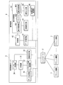
図1は、実施形態の監視制御システムの構成を示す機能ブロック図であり、本実施形態と関係する機能ブロックのみを抽出して示してある。同図に示すように監視制御システムは、プラント機器1と、コントローラ2と、監視制御サーバ3と、監視端末4とを備える。図1に示す監視制御システムは監視システムの一例であり、監視端末4はメッセージ表示装置の一例である。同図においては、コントローラ2と監視端末4をそれぞれ1台のみ示しているが、それぞれ複数台が監視制御サーバ3に接続され得る。監視制御サーバ3と、コントローラ2及び監視端末4とは、例えば、IP(Internet Protocol)を用いた通信ネットワークにより接続される。
Hereinafter, a message display device, a monitoring system, a message display method, and a program according to embodiments will be described with reference to the drawings.
FIG. 1 is a functional block diagram showing a configuration of the monitoring control system of the embodiment, and only functional blocks related to the present embodiment are extracted and shown. As shown in the figure, the monitoring control system includes a plant device 1, a
プラント機器1は、監視制御対象のプラントを構成する機器である。プラント機器1は、例えば、ポンプ、ブロア、各種センサ(温度計、水位計、電力計、電圧計など)であるが、これらに限定されない。プラント機器1は、プロセス値を表す信号をコントローラ2へ送信する。プロセス値は、監視対象のプラント機器1(監視対象機器)の状況を表す値である。例えば、プロセス値は、温度、水位、流入水量、流出水量、特定の物質の濃度、電力、電圧などの計測値や、プラント機器1の稼働状態(on/off状態、回転数、送風量など)等を表す値であるが、これらに限定されない。
The plant equipment 1 is equipment that constitutes a plant to be monitored and controlled. The plant equipment 1 is, for example, a pump, a blower, and various sensors (such as a thermometer, a water level meter, a wattmeter, and a voltmeter), but is not limited thereto. The plant equipment 1 transmits a signal representing the process value to the
コントローラ2は、監視制御サーバ3から受信した制御指示信号に従ってプラント機器1を制御する。また、コントローラ2は、プラント機器1から受信したプロセス値と、プロセス値の種類とを設定したプロセス値通知信号を、監視制御サーバ3に送信する。コントローラ2は、各プラント機器1との間で電気信号を送受信するため、それぞれ異なる信号線により接続される。従って、いずれの種類のプロセス値であるかは、そのプロセス値を示す信号を受信した信号線や物理ポートにより識別することができる。また、プロセス値を電気信号以外の信号により送受信する場合、コントローラ2は、プロセス値を示す信号に付加されている他の情報(例えば、IP信号のアドレスの情報やペイロードに設定されている種別の情報)を用いてプロセス値の種類を識別してもよい。
The
監視制御サーバ3は、1台以上のコンピュータサーバにより実現される。監視制御サーバ3は、記憶部31と、プロセス値受信部32と、制御指示部33と、メッセージ生成部34と、データ送信部35とを備える。
The
記憶部31は、プロセス値情報、メッセージ履歴情報、及び、設備情報を記憶する。プロセス値情報は、現在のプロセス値を種類毎に示す。メッセージ履歴情報は、メッセージの発生時刻と、メッセージ種別と、メッセージの対象機器と、メッセージとを対応づけた情報である。設備情報は、各区分に属するプラント機器1を示す情報である。区分は、任意に設定することができる。例えば、区分は、発電用のプラント、水処理用のプラント、…などとしてもよく、A機場のプラント、B機場のプラント、…などとしてもよい。
The
プロセス値受信部32は、コントローラ2からプロセス値通知信号を受信する受信部として動作する。プロセス値受信部32は、受信したプロセス値通知信号が示すプロセス値を、そのプロセス値の種類に応じて工学値に変換する。プロセス値受信部32は、プロセス値の種類と、工学値に変換されたプロセス値とを対応付けて記憶部31に記憶されるプロセス値情報に書き込む。
The process
制御指示部33は、監視端末4からプラント機器1に対する制御指示を受信する受信部として動作する。制御指示部33は、監視端末4から受信した制御指示に従ってプラント機器1を制御するよう指示する制御指示信号を、制御対象のプラント機器1を制御するコントローラ2に送信する。
The
メッセージ生成部34は、プラント機器1の状況を表すデータに基づいて、そのプラント機器1の状況を示すメッセージを生成する。プラント機器1の状況を表すデータは、プロセス値受信部32が記憶部31に記憶されるプロセス値情報に書き込んだプロセス値及びそのプロセス値の種類や、プラント機器1に対する制御指示である。メッセージ生成部34は、生成したメッセージと、メッセージの発生時刻と、メッセージ種別と、対象機器とを対応付けて記憶部31に記憶されるメッセージ履歴情報に書き込む。メッセージ生成部34は、プロセス値の種類及びプロセス値に基づいて、あるいは、制御指示が示す制御対象のプラント機器1及び制御内容に基づいて、メッセージを生成するか否かを判断する。メッセージを生成する場合、メッセージ生成部34は、メッセージの内容やメッセージ種別、対象機器を、プロセス値の種類及びプロセス値に基づいて、あるいは、制御指示が示す制御対象のプラント機器1及び制御内容に基づいて、所定のルールに従って判断する。
データ送信部35は、記憶部31に記憶されているプロセス値情報、メッセージ履歴情報、及び、設備情報を、監視端末4に出力する。
The
The
監視端末4は、HMI(ヒューマンマシーンインタフェース)であり、例えば、ワークステーションなどのコンピュータ端末により実現される。なお、監視制御サーバ3と監視端末4とが同一のコンピュータ装置により実現されてもよい。監視端末4は、データ取得部41と、記憶部42と、表示制御部43と、画像表示部44と、操作入力部45と、制御指示送信部46とを備える。
データ取得部41は、監視制御サーバ3からプロセス情報、メッセージ履歴情報、及び、設備情報を取得する。データ取得部41は、メッセージ履歴情報を取得することにより、監視対象のプラント機器1の状況を表すデータに基づいて生成された時系列のメッセージを取得するメッセージ取得部として動作する。記憶部42は、データ取得部41が監視制御サーバ3から取得したプロセス情報、メッセージ履歴情報、及び、設備情報を記憶する。
The monitoring terminal 4 is an HMI (Human Machine Interface), and is realized by a computer terminal such as a workstation. Note that the
The
表示制御部43は、記憶部42に記憶されるプロセス情報及びメッセージ履歴情報に基づいてプラントの状態を表示する監視画面を生成し、画像表示部44に表示させる。表示制御部43は、表示更新部431と、バッファ432と、表示切替部433とを備える。
表示更新部431は、新たなメッセージ情報がメッセージ履歴情報に追加された場合、発生時刻が新しい順に選択した所定数のメッセージ情報に基づくメッセージを、発生時刻順に監視画面上の所定の表示領域に表示する。本実施形態では、この所定の表示領域を、2件分のメッセージを表示可能な最新メッセージ表示領域とする。
バッファ432は、表示更新部431が最新メッセージ表示領域に表示させたメッセージをバッファリング(記憶)する。バッファリングするメッセージの件数は、例えば、20件など、最新メッセージ表示領域に過去に遡って表示させることができる件数である。
表示切替部433は、操作入力部45により表示対象切替指示が入力された場合、最新メッセージ表示領域に表示中のメッセージよりも過去に表示されたメッセージをバッファ432から取得し、時系列に最新メッセージ表示領域に表示する。
The
When new message information is added to the message history information, the
The
When the display input switching instruction is input from the
画像表示部44は、ディスプレイであり、画面を表示する。
操作入力部45は、ユーザ操作を入力するためのインタフェースであり、例えば、マウスやキーである。画像表示部44がタッチパネルの場合、操作入力部45は、タッチパネルに配されたタッチセンサである。以下では、操作入力部45がマウスである場合を例に説明する。
制御指示送信部46は、ユーザが操作入力部45によりプラント機器1に対する制御の指示を入力すると、その入力に基づく制御指示を監視制御サーバ3に送信する。
The
The
When the user inputs a control instruction for the plant equipment 1 through the
図2は、メッセージ履歴情報の例を示す図である。同図に示すように、メッセージ履歴情報5は、メッセージの発生時刻と、イベント種別と、メッセージの内容とを対応付けたメッセージ情報からなる。同図にメッセージ履歴情報には、発生時刻が新しいメッセージ情報から順に、メッセージ情報5−1、5−2、5−3、…が登録されている。メッセージ種別は、通知、操作、アラームなどである。通知は、プラント機器1の動作等を通知するメッセージであり、操作は、ユーザ操作によりプラント機器1に指示した制御内容等を示すメッセージである。アラームは、さらに、重故障、軽故障、…などさらに詳細なメッセージ種別としてもよい。対象機器は、いずれのプラント機器1に関するメッセージであるかを示す。なお、メッセージの内容にプラント機器1を特定する情報が含まれる場合、その情報を対象機器の情報として用いてもよい。
FIG. 2 is a diagram illustrating an example of message history information. As shown in the figure, the
次に、監視端末4の表示制御部43が画像表示部44に表示させる監視画面を説明する。
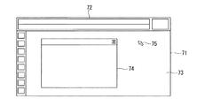
図3は、メッセージを自動更新しているときの監視画面71を示す図である。監視画面71は、最新メッセージ表示領域72(メッセージ表示領域)と、個別監視画面表示領域73とを有する。個別監視画面表示領域73は、プラントの状態を表示するフロー画面や、プラントを構成する設備の時系列の状態を表示するトレンドグラフ画面などの個別監視画面74を表示させる領域である。表示制御部43は、個別監視画面74を、記憶部42に記憶されるプロセス情報やメッセージ履歴情報に基づいて表示させる。個別監視画面74の表示上限数は予め決められている。
Next, a monitoring screen displayed on the
FIG. 3 is a diagram showing the
監視端末4の表示更新部431は、最新メッセージ表示領域72に、現在から最新の2件分のメッセージを表示する。機器の稼働等により新たなメッセージが発生し、メッセージ履歴情報が更新されると、表示更新部431は、最新メッセージ表示領域72にその時点における最新の2件のメッセージを表示する。このとき、表示更新部431は、最新メッセージ表示領域72において、最新のメッセージが最も上の行に表示されるように、発生時刻順に並べてメッセージを表示する。このように、メッセージが更新された際には、最新メッセージ表示領域72の表示内容は自動で更新され、常に現在から最新の2件分のメッセージが表示される。表示更新部431は、メッセージの背景色やメッセージの文字色を、イベント種別に応じて決定する。
The
表示更新部431は、最新メッセージ表示領域72に新たにメッセージを表示するたびに、その表示したメッセージの情報をバッファ432に書き込む。バッファ432に書き込むメッセージの情報は、表示したメッセージに背景色やメッセージの文字色などのスタイルを付加した情報でもよく、表示したメッセージの画像データでもよく、メッセージ履歴情報から取得したメッセージ情報でもよい。
Each time the
ユーザは、常に表示されている最新の2件を超える件数のメッセージを確認したい場合、最新メッセージ表示領域72の選択操作を行う。具体的には、ユーザは、マウス(操作入力部45)を操作して、マウスポインタ75を最新メッセージ表示領域72の上に移動させてクリックする。この操作は、最新メッセージ表示領域72における表示対象を切り換えるための所定の指示に相当する。この指示を、表示対象切換指示と記載する。
When the user wants to check the number of messages exceeding the latest two that are always displayed, the user performs an operation of selecting the latest
図4は、最新メッセージ表示領域が選択されたときの監視画面を示す図である。ユーザがマウスにより最新メッセージ表示領域72の選択操作を行うと、表示切替部433は、最新メッセージ表示領域72に最新のメッセージが表示されていない可能性があることを示す態様で表示を行う。例えば、同図では、最新メッセージ表示領域72を囲んでいる線の表示を、赤色の太線に変更して表示している。つまり、この太線は、最新メッセージ表示領域72に表示されているメッセージ内容が、最新の2件のメッセージを表示しているものではない可能性があることを示すマーキングの役割を持つ。赤色の太線の表示により、ユーザが、最新メッセージ表示領域72に最新ではない過去のメッセージが表示されている状態を、最新のメッセージが表示されている状態と誤解しないようにする。
図4では、最新メッセージ表示領域72に最新のメッセージが表示されていない可能性があることを示す態様として、最新メッセージ表示領域72を囲む線を変更する場合を例に示したが、他の態様であってもよい。例えば、表示切替部433は、最新メッセージ表示領域72以外の監視画面71の表示をグレーアウトするなど、最新メッセージ表示領域72以外の色や明るさを変更して表示してもよい。
FIG. 4 is a diagram showing a monitoring screen when the latest message display area is selected. When the user performs an operation of selecting the latest
In FIG. 4, as an example showing that there is a possibility that the latest message may not be displayed in the latest
図5は、表示対象切替指示が入力されたときの監視画面を示す図である。
最新メッセージ表示領域72が選択されている、つまり、最新メッセージ表示領域72を囲む線が赤色の太線で表示されている状態で、ユーザがマウスのホイール6を操作する。表示切替部433は、最新メッセージ表示領域72内の表示内容をスクロールさせる。スクロールした際に最新メッセージ表示領域72内に表示させる対象は、表示制御部43がバッファ432にバッファリングしていた過去所定件数分(例えば20件)のメッセージである。ユーザがホイール6を下に回転させた場合、表示切替部433は、バッファ432からそのホイール操作量分応じた過去のメッセージの情報を読み出して順次スクロール表示させる。
FIG. 5 is a diagram illustrating a monitoring screen when a display object switching instruction is input.
The user operates the
例えば、最新メッセージ表示領域72にメッセージ情報5−1及び5−2に基づくメッセージが表示されているとする。ユーザがホイール6を下に回転させると、表示切替部433は、メッセージ情報5−2及び5−3に基づくメッセージ、メッセージ情報5−3及び5−4に基づくメッセージ、メッセージ情報5−4及び5−5に基づくメッセージ、…と切り替えて表示する。表示切替部433は、表示対象を切り変えた場合でも、最新メッセージ表示領域72に表示させている中で、新しい発生時刻のメッセージほど上の行に表示する。これにより、ユーザが履歴メッセージを表示するための専用の画面を別途表示することなく、バッファ432にバッファリングしている件数分の過去のメッセージを確認することが可能となる。
For example, it is assumed that a message based on the message information 5-1 and 5-2 is displayed in the latest
なお、表示切替部433は、ユーザがホイール6を上に回転させた場合、そのホイール操作量分応じて過去のメッセージを現在に近い方向に順次スクロール表示させる。例えば、最新メッセージ表示領域72にメッセージ情報5−10及び5−11に基づくメッセージが表示されているとする。ユーザがホイール6を上に回転させると、表示切替部433は、メッセージ情報5−9及び5−10に基づくメッセージ、メッセージ情報5−8及び5−9に基づくメッセージ、メッセージ情報5−7及び5−8に基づくメッセージ、…と切り替えて表示する。
このように、表示切替部433は、過去方向への移動を示す表示対象切替指示が入力された場合、最新メッセージ表示領域72に、現在表示中のメッセージから発生時刻を過去方向に順に移動させてメッセージを時系列に表示する。また、現在方向への移動を示す表示対象切替指示が入力された場合、表示切替部433は、最新メッセージ表示領域72に、表示中のメッセージから発生時刻を現在方向に順に移動させてメッセージを時系列に表示する。なお、マウスのホイール6を回転する操作に代えて、キーボードの上矢印キーや下矢印キーを押下する操作などでもよい。
When the user rotates the
As described above, when the display object switching instruction indicating the movement in the past direction is input, the
そして、ユーザが最新メッセージ表示領域72の外をクリックすると、表示切替部433は、最新メッセージ表示領域72を囲む太線を消去する。表示更新部431は、最新メッセージ表示領域72に、現在からの最新の2件のメッセージを表示する。
When the user clicks outside the latest
次に、監視制御システムの動作について説明する。
監視制御サーバ3のプロセス値受信部32は、随時、コントローラ2からプロセス値通知信号を受信する。プロセス値受信部32は、受信したプロセス値通知信号が示すプロセス値を工学値に変換し、プロセス値の種類と対応付けて記憶部31に記憶されるプロセス値情報に書き込む。メッセージ生成部34は、プロセス値情報に書き込まれたプロセス値及びそのプロセス値の種類に基づいてメッセージを生成した場合、メッセージの内容、発生時刻、メッセージ種別、及び、対象機器を対応付けて記憶部31に記憶されるメッセージ履歴情報に書き込む。
Next, the operation of the monitoring control system will be described.
The process
また、監視制御サーバ3の制御指示部33は、随時、監視端末4の制御指示送信部46からユーザ操作に基づく制御指示を受信し、受信した制御指示に従ってプラント機器1を制御するよう指示する制御指示信号をコントローラ2に送信する。メッセージ生成部34は、監視端末4から受信した制御指示に基づいてメッセージを生成した場合、メッセージの内容、発生時刻、メッセージ種別、及び、対象機器を対応付けて記憶部31に記憶されるメッセージ履歴情報に書き込む。
Moreover, the control instruction |
監視制御サーバ3のデータ送信部35は、情報が更新される度に、周期的に、又は、監視端末4からの要求を受けて、記憶部31からプロセス値情報、メッセージ履歴情報、及び、設備情報を読み出して監視端末4に出力する。監視端末4のデータ取得部41は、監視制御サーバ3から受信したプロセス値情報、メッセージ履歴情報、及び、設備情報を記憶部42に書き込む。なお、データ取得部41は、これらの情報を非同期に取得し得る。
The
図6は、監視端末4による最新メッセージ表示領域の表示制御処理を示すフロー図である。
監視端末4の表示更新部431は、メッセージ履歴情報に登録されている最新の2件分のメッセージ情報に基づくメッセージを、最新メッセージ表示領域72に表示する(ステップS110)。例えば、新たなメッセージが発生し、記憶部42に記憶されるメッセージ履歴情報にメッセージ情報が追加された場合、表示更新部431は、更新されたメッセージ履歴情報からまだメッセージを表示させていない追加のメッセージ情報を読み出す。表示更新部431は、最新メッセージ表示領域72に現在表示させているメッセージのうち最も発生時刻が古いメッセージを消去し、残りの表示中のメッセージを下に1行ずらして表示する。表示更新部431は、読み出したメッセージ情報に基づくメッセージを最新メッセージ表示領域72の最も上の行に表示する。表示更新部431は、表示させた最新のメッセージの情報をバッファ432に書き込む。なお、バッファ432にバッファリングする上限数のメッセージの情報が既に記憶されている場合、表示更新部431は、最も古い発生時刻のメッセージの情報を消去してから最新のメッセージの情報を書き込む。
メッセージを表示させていない追加のメッセージ情報が複数ある場合、表示更新部431は、最も発生時刻が古い追加のメッセージ情報から順に、上記の処理を行う。
FIG. 6 is a flowchart showing display control processing of the latest message display area by the monitoring terminal 4.
The
When there are a plurality of additional message information that does not display a message, the
最新メッセージ表示領域の選択操作がされない間(ステップS115:NO)、表示更新部431は、ステップS110の処理を繰り返す。ユーザがマウスを操作し、最新メッセージ表示領域72上にマウスポインタ75を移動させてクリックすると(ステップS115:YES)、表示切替部433は、表示対象切替指示の入力を行うための操作が行われたことを検出する。表示切替部433は、最新メッセージ表示領域72を囲んでいる線の表示を、赤色の太線に変更して表示する(ステップS120)。
While the selection operation of the latest message display area is not performed (step S115: NO), the
ユーザがマウスのホイール6を操作すると(ステップS125:YES)、表示切替部433は、最新メッセージ表示領域72内の表示内容をスクロールさせる。表示切替部433は、ホイール6の操作量や操作方向に応じて過去に最新メッセージ表示領域72に表示させたメッセージをバッファ432から取得して順次スクロール表示させる(ステップS130)。
When the user operates the mouse wheel 6 (step S125: YES), the
スクロール操作が行われなかった場合(ステップS125:NO)、あるいは、スクロール操作に応じて過去のメッセージを表示させた後(ステップS130)、表示切替部433は、ステップS135の処理を行う。つまり、表示切替部433は、最新メッセージ表示領域72の選択終了操作が行われたか否かを判断する(ステップS135)。選択終了操作が行われていないと判断した場合、表示切替部433は、ステップS125からの処理を繰り返す。ユーザが最新メッセージ表示領域72の外をクリックすると、表示切替部433は、選択終了操作が行われたと判断し(ステップS135:YES)、最新メッセージ表示領域72を囲む太線を消去する(ステップS140)。表示制御部43は、ステップS115において最新メッセージ表示領域の選択操作がされたときに表示していたメッセージを最新メッセージ表示領域72に表示させた後、ステップS110からの処理を繰り返す。
When the scroll operation is not performed (step S125: NO), or after displaying a past message according to the scroll operation (step S130), the
なお、監視端末4は、メッセージの表示領域を拡大し、メッセージの履歴を表示してもよい。
図7は、表示領域を拡大してメッセージを表示するときの表示画面を示す図である。
ユーザが監視画面71の最新メッセージ表示領域72上にマウスポインタ75を移動させてクリックすると、表示切替部433は、最新メッセージ表示領域72の下にドロップダウンリスト76を表示する。表示切替部433は、ドロップダウンリスト76内にバッファ432から読み出した過去のメッセージを発生時刻順に並べて時系列に表示する。ユーザがマウスのホイール6を操作すると、表示切替部433は、ドロップダウンリスト76内の表示内容をスクロールさせる。表示切替部433は、ホイール6の操作量や操作方向に応じて過去に最新メッセージ表示領域72に表示されたメッセージを順次スクロール表示させる。
The monitoring terminal 4 may expand the message display area and display the message history.
FIG. 7 is a diagram showing a display screen when a display area is enlarged and a message is displayed.
When the user moves and clicks the
なお、ユーザが、操作入力部45により表示対象のメッセージ種別を入力してもよい。表示更新部431及び表示切替部433は、表示対象のメッセージ種別が設定されているメッセージ情報に基づくメッセージのみを、最新メッセージ表示領域72又はドロップダウンリスト76へ表示する。
また、ユーザが、操作入力部45により表示対象の区分を入力してもよい。表示更新部431及び表示切替部433は、表示対象の区分に属するプラント機器1が対象機器であるメッセージ情報に基づくメッセージのみを最新メッセージ表示領域72又はドロップダウンリスト76へ表示する。表示更新部431及び表示切替部433は、記憶部42に記憶されている設備情報を参照して、メッセージ情報に設定されている対象機器が表示対象の区分に属するか否かを判断する。
Note that the user may input a message type to be displayed through the
In addition, the user may input a display target category by the
上述の実施形態によれば、ユーザは、過去に発生したメッセージを、専用の画面を表示することなく、常時表示されているHMI画面上の最新メッセージ表示領域を利用して確認することができる。 According to the above-described embodiment, the user can check a message that has occurred in the past by using the latest message display area on the HMI screen that is always displayed without displaying a dedicated screen.
以上説明した少なくともひとつの実施形態によれば、表示切替部を持つことにより、最新メッセージ表示機能が占有する領域を拡張することなく、従来の件数を超えるメッセージの履歴を、専用の画面を表示することなく容易に確認可能とすることができる。また、メッセージの履歴を専用の画面により表示させないため、個別監視画面を上限数まで表示させることができる。 According to at least one embodiment described above, by having a display switching unit, a dedicated screen is displayed for a history of messages exceeding the conventional number without expanding the area occupied by the latest message display function. It can be easily confirmed without any problem. Further, since the message history is not displayed on the dedicated screen, the individual monitoring screen can be displayed up to the upper limit number.
上述した実施形態における監視制御サーバ3及び監視端末4の一部又は全ての機能をコンピュータで実現するようにしてもよい。その場合、監視制御サーバ3及び監視端末4の機能を実現するためのプログラムをコンピュータ読み取り可能な記録媒体に記録して、この記録媒体に記録されたプログラムをコンピュータシステムに読み込ませ、実行することによって実現してもよい。なお、ここでいう「コンピュータシステム」とは、OSや周辺機器等のハードウェアを含むものとする。また、「コンピュータ読み取り可能な記録媒体」とは、フレキシブルディスク、光磁気ディスク、ROM、CD−ROM等の可搬媒体、コンピュータシステムに内蔵されるハードディスク等の記憶装置のことをいう。さらに「コンピュータ読み取り可能な記録媒体」とは、インターネット等のネットワークや電話回線等の通信回線を介してプログラムを送信する場合の通信線のように、短時間の間、動的にプログラムを保持するもの、その場合のサーバやクライアントとなるコンピュータシステム内部の揮発性メモリのように、一定時間プログラムを保持しているものも含んでもよい。また上記プログラムは、前述した機能の一部を実現するためのものであってもよく、さらに前述した機能をコンピュータシステムにすでに記録されているプログラムとの組み合わせで実現できるものであってもよい。
A part or all of the functions of the
本発明のいくつかの実施形態を説明したが、これらの実施形態は、例として提示したものであり、発明の範囲を限定することは意図していない。これら実施形態は、その他の様々な形態で実施されることが可能であり、発明の要旨を逸脱しない範囲で、種々の省略、置き換え、変更を行うことができる。これら実施形態やその変形は、発明の範囲や要旨に含まれると同様に、特許請求の範囲に記載された発明とその均等の範囲に含まれるものである。 Although several embodiments of the present invention have been described, these embodiments are presented by way of example and are not intended to limit the scope of the invention. These embodiments can be implemented in various other forms, and various omissions, replacements, and changes can be made without departing from the spirit of the invention. These embodiments and their modifications are included in the scope and gist of the invention, and are also included in the invention described in the claims and the equivalents thereof.
1…プラント機器、2…コントローラ、3…監視制御サーバ、4…監視端末、31…記憶部、32…プロセス値受信部、33…制御指示部、34…メッセージ生成部、35…データ送信部、41…データ取得部、42…記憶部、43…表示制御部、44…画像表示部、45…操作入力部、431…表示更新部、432…バッファ、433…表示切替部
DESCRIPTION OF SYMBOLS 1 ... Plant equipment, 2 ... Controller, 3 ... Monitoring control server, 4 ... Monitoring terminal, 31 ... Memory | storage part, 32 ... Process value receiving part, 33 ... Control instruction | indication part, 34 ... Message production | generation part, 35 ... Data transmission part, DESCRIPTION OF
Claims (7)
監視端末の画面内のメッセージ表示領域に、発生時刻が最も新しい前記メッセージから順に所定数の前記メッセージを表示し、所定の指示が入力された場合、前記メッセージ表示領域に、表示中の前記メッセージよりも過去に前記メッセージ表示領域に表示された前記メッセージを時系列に表示する表示制御部と、
を備えるメッセージ表示装置。 A message acquisition unit that acquires time-series messages related to the status of monitored devices;
In the message display area in the screen of the monitoring terminal, a predetermined number of the messages are displayed in order from the newest message, and when a predetermined instruction is input, the message display area displays the message being displayed. A display control unit for displaying the messages displayed in the message display area in the past in time series,
A message display device comprising:
請求項1に記載のメッセージ表示装置。 The display control unit performs display in a mode indicating that the latest message may not be displayed in the message display area when an operation for inputting the predetermined instruction is performed.
The message display device according to claim 1.
請求項1又は請求項2に記載のメッセージ表示装置。 When an instruction indicating movement in the past direction is input, the display control unit displays the messages in time series in the message display area by sequentially moving the generation time in the past direction from the message being displayed. When an instruction indicating movement in the current direction is input, the message is displayed in chronological order in the message display area by sequentially moving the generation time in the current direction rather than the message being displayed.
The message display device according to claim 1 or 2.
請求項1に記載のメッセージ表示装置。 When the predetermined instruction is input, the display control unit displays the message displayed in the message display area in the past than the message being displayed in time series in the enlarged message display area.
The message display device according to claim 1.
前記データに基づいて前記監視対象機器の状況に関するメッセージを生成するメッセージ生成部と、
監視端末の画面内のメッセージ表示領域に、発生時刻が最も新しい前記メッセージから順に所定数の前記メッセージを表示し、所定の指示が入力された場合、前記メッセージ表示領域に、表示中の前記メッセージよりも過去に前記メッセージ表示領域に表示された前記メッセージを時系列に表示する表示制御部と、
を備える監視システム。 A receiver that receives data representing the status of the monitored device;
A message generation unit that generates a message related to the status of the monitored device based on the data;
In the message display area in the screen of the monitoring terminal, a predetermined number of the messages are displayed in order from the newest message, and when a predetermined instruction is input, the message display area displays the message being displayed. A display control unit for displaying the messages displayed in the message display area in the past in time series,
A monitoring system comprising:
監視端末の画面内のメッセージ表示領域に、発生時刻が最も新しい前記メッセージから順に所定数の前記メッセージを表示し、所定の指示が入力された場合、前記メッセージ表示領域に、表示中の前記メッセージよりも過去に前記メッセージ表示領域に表示された前記メッセージを時系列に表示する表示制御ステップと、
を有するメッセージ表示方法。 A message acquisition step for acquiring time-series messages related to the status of monitored devices;
In the message display area in the screen of the monitoring terminal, a predetermined number of the messages are displayed in order from the newest message, and when a predetermined instruction is input, the message display area displays the message being displayed. A display control step for displaying the messages displayed in the message display area in the past in time series,
A message display method.
監視対象機器の状況に関する時系列のメッセージを取得するメッセージ取得ステップと、
監視端末の画面内のメッセージ表示領域に、発生時刻が最も新しい前記メッセージから順に所定数の前記メッセージを表示し、所定の指示が入力された場合、前記メッセージ表示領域に、表示中の前記メッセージよりも過去に前記メッセージ表示領域に表示された前記メッセージを時系列に表示する表示制御ステップと、
を実行させるプログラム。 On the computer,
A message acquisition step for acquiring time-series messages related to the status of monitored devices;
In the message display area in the screen of the monitoring terminal, a predetermined number of the messages are displayed in order from the newest message, and when a predetermined instruction is input, the message display area displays the message being displayed. A display control step for displaying the messages displayed in the message display area in the past in time series,
A program that executes
Priority Applications (1)
| Application Number | Priority Date | Filing Date | Title |
|---|---|---|---|
| JP2015095372A JP6856310B2 (en) | 2015-05-08 | 2015-05-08 | Message display device, monitoring system, message display method and program |
Applications Claiming Priority (1)
| Application Number | Priority Date | Filing Date | Title |
|---|---|---|---|
| JP2015095372A JP6856310B2 (en) | 2015-05-08 | 2015-05-08 | Message display device, monitoring system, message display method and program |
Publications (2)
| Publication Number | Publication Date |
|---|---|
| JP2016212607A true JP2016212607A (en) | 2016-12-15 |
| JP6856310B2 JP6856310B2 (en) | 2021-04-07 |
Family
ID=57551748
Family Applications (1)
| Application Number | Title | Priority Date | Filing Date |
|---|---|---|---|
| JP2015095372A Active JP6856310B2 (en) | 2015-05-08 | 2015-05-08 | Message display device, monitoring system, message display method and program |
Country Status (1)
| Country | Link |
|---|---|
| JP (1) | JP6856310B2 (en) |
Citations (7)
| Publication number | Priority date | Publication date | Assignee | Title |
|---|---|---|---|---|
| JPH05216613A (en) * | 1992-02-04 | 1993-08-27 | Oki Electric Ind Co Ltd | System message controller |
| JPH11167478A (en) * | 1997-12-02 | 1999-06-22 | Yokogawa Electric Corp | Warning display method and distributed control system using it |
| JP2000347724A (en) * | 1999-06-04 | 2000-12-15 | Toshiba Corp | Plant controller |
| JP2001084026A (en) * | 1999-09-10 | 2001-03-30 | Toshiba Corp | Monitor and control equipment |
| JP2002091561A (en) * | 2000-09-12 | 2002-03-29 | Toshiba Corp | Supervisory controller and storage medium |
| JP2003067050A (en) * | 2001-08-29 | 2003-03-07 | Yokogawa Electric Corp | Display device for monitoring operation |
| JP2014026473A (en) * | 2012-07-27 | 2014-02-06 | Canon Marketing Japan Inc | Information processing device, control method for information processing device, program, and recording medium |
-
2015
- 2015-05-08 JP JP2015095372A patent/JP6856310B2/en active Active
Patent Citations (7)
| Publication number | Priority date | Publication date | Assignee | Title |
|---|---|---|---|---|
| JPH05216613A (en) * | 1992-02-04 | 1993-08-27 | Oki Electric Ind Co Ltd | System message controller |
| JPH11167478A (en) * | 1997-12-02 | 1999-06-22 | Yokogawa Electric Corp | Warning display method and distributed control system using it |
| JP2000347724A (en) * | 1999-06-04 | 2000-12-15 | Toshiba Corp | Plant controller |
| JP2001084026A (en) * | 1999-09-10 | 2001-03-30 | Toshiba Corp | Monitor and control equipment |
| JP2002091561A (en) * | 2000-09-12 | 2002-03-29 | Toshiba Corp | Supervisory controller and storage medium |
| JP2003067050A (en) * | 2001-08-29 | 2003-03-07 | Yokogawa Electric Corp | Display device for monitoring operation |
| JP2014026473A (en) * | 2012-07-27 | 2014-02-06 | Canon Marketing Japan Inc | Information processing device, control method for information processing device, program, and recording medium |
Also Published As
| Publication number | Publication date |
|---|---|
| JP6856310B2 (en) | 2021-04-07 |
Similar Documents
| Publication | Publication Date | Title |
|---|---|---|
| US10671503B2 (en) | Mobile application interactive user interface for a remote computing device monitoring a test device | |
| US11665223B1 (en) | Automated network discovery for industrial controller systems | |
| JP2016502179A (en) | Apparatus and method for dynamic operation based on context | |
| CN111800454A (en) | Visual data display system and visual page screen projection method | |
| JP6002856B2 (en) | Monitoring system and monitoring method | |
| EP3321752A1 (en) | Controller, control method for controller, and information processing program | |
| JP2017068469A (en) | Information processing device, control method, and program | |
| JP6856310B2 (en) | Message display device, monitoring system, message display method and program | |
| CN112631939A (en) | Use case configuration method, use case configuration device, and readable storage medium | |
| CN109765850B (en) | Control system | |
| JP2009151501A (en) | Document transmission device and document transmission program, document reception device and document reception program, and document system | |
| CN104166504A (en) | Fast scrolling device, method and terminal | |
| JP2014021781A (en) | Portable information terminal device, server device and apparatus monitoring method | |
| JP7091017B2 (en) | Operation terminal, control method and computer program | |
| CN111492421B (en) | Monitoring device, monitoring method, and monitoring program | |
| JP6604455B1 (en) | Display control method, display control apparatus, and program | |
| JP6083067B2 (en) | Display device and program | |
| JP2016048475A (en) | Screen display controller, screen display device and screen display control method | |
| JP7453285B2 (en) | Management server | |
| JP6218680B2 (en) | Network analysis support device, network analysis support method, and program | |
| JP2016151974A (en) | Hyman-machine interface system, human-machine interface device, and program | |
| JP6505511B2 (en) | Display control apparatus, distribution apparatus, display control system, display control method and program | |
| JP2023031722A (en) | Log information analysis support device, analysis system, log information analysis support method, and program | |
| JP6776041B2 (en) | Display control device and display control program | |
| CN105653110B (en) | Method for creating rule based on electronic map of monitoring system |
Legal Events
| Date | Code | Title | Description |
|---|---|---|---|
| A711 | Notification of change in applicant |
Free format text: JAPANESE INTERMEDIATE CODE: A711 Effective date: 20170912 Free format text: JAPANESE INTERMEDIATE CODE: A712 Effective date: 20170912 |
|
| A621 | Written request for application examination |
Free format text: JAPANESE INTERMEDIATE CODE: A621 Effective date: 20180309 |
|
| A977 | Report on retrieval |
Free format text: JAPANESE INTERMEDIATE CODE: A971007 Effective date: 20181130 |
|
| A131 | Notification of reasons for refusal |
Free format text: JAPANESE INTERMEDIATE CODE: A131 Effective date: 20181211 |
|
| A521 | Request for written amendment filed |
Free format text: JAPANESE INTERMEDIATE CODE: A523 Effective date: 20190212 |
|
| A02 | Decision of refusal |
Free format text: JAPANESE INTERMEDIATE CODE: A02 Effective date: 20190723 |
|
| A521 | Request for written amendment filed |
Free format text: JAPANESE INTERMEDIATE CODE: A523 Effective date: 20191023 |
|
| C60 | Trial request (containing other claim documents, opposition documents) |
Free format text: JAPANESE INTERMEDIATE CODE: C60 Effective date: 20191023 |
|
| A911 | Transfer to examiner for re-examination before appeal (zenchi) |
Free format text: JAPANESE INTERMEDIATE CODE: A911 Effective date: 20191030 |
|
| C21 | Notice of transfer of a case for reconsideration by examiners before appeal proceedings |
Free format text: JAPANESE INTERMEDIATE CODE: C21 Effective date: 20191105 |
|
| A912 | Re-examination (zenchi) completed and case transferred to appeal board |
Free format text: JAPANESE INTERMEDIATE CODE: A912 Effective date: 20191220 |
|
| C211 | Notice of termination of reconsideration by examiners before appeal proceedings |
Free format text: JAPANESE INTERMEDIATE CODE: C211 Effective date: 20191224 |
|
| C22 | Notice of designation (change) of administrative judge |
Free format text: JAPANESE INTERMEDIATE CODE: C22 Effective date: 20200825 |
|
| C22 | Notice of designation (change) of administrative judge |
Free format text: JAPANESE INTERMEDIATE CODE: C22 Effective date: 20201013 |
|
| C13 | Notice of reasons for refusal |
Free format text: JAPANESE INTERMEDIATE CODE: C13 Effective date: 20201027 |
|
| A521 | Request for written amendment filed |
Free format text: JAPANESE INTERMEDIATE CODE: A523 Effective date: 20201224 |
|
| C23 | Notice of termination of proceedings |
Free format text: JAPANESE INTERMEDIATE CODE: C23 Effective date: 20210112 |
|
| C03 | Trial/appeal decision taken |
Free format text: JAPANESE INTERMEDIATE CODE: C03 Effective date: 20210216 |
|
| C30A | Notification sent |
Free format text: JAPANESE INTERMEDIATE CODE: C3012 Effective date: 20210216 |
|
| A61 | First payment of annual fees (during grant procedure) |
Free format text: JAPANESE INTERMEDIATE CODE: A61 Effective date: 20210318 |
|
| R150 | Certificate of patent or registration of utility model |
Ref document number: 6856310 Country of ref document: JP Free format text: JAPANESE INTERMEDIATE CODE: R150 |