JP2016202061A - Work vehicle - Google Patents
Work vehicle Download PDFInfo
- Publication number
- JP2016202061A JP2016202061A JP2015086811A JP2015086811A JP2016202061A JP 2016202061 A JP2016202061 A JP 2016202061A JP 2015086811 A JP2015086811 A JP 2015086811A JP 2015086811 A JP2015086811 A JP 2015086811A JP 2016202061 A JP2016202061 A JP 2016202061A
- Authority
- JP
- Japan
- Prior art keywords
- growth
- sensor
- fertilizer
- vehicle body
- traveling vehicle
- Prior art date
- Legal status (The legal status is an assumption and is not a legal conclusion. Google has not performed a legal analysis and makes no representation as to the accuracy of the status listed.)
- Pending
Links
- 230000012010 growth Effects 0.000 claims abstract description 266
- 238000001514 detection method Methods 0.000 claims description 111
- 239000003337 fertilizer Substances 0.000 claims description 102
- 230000004720 fertilization Effects 0.000 claims description 54
- 238000005259 measurement Methods 0.000 claims description 53
- 230000007246 mechanism Effects 0.000 claims description 53
- 230000003028 elevating effect Effects 0.000 claims description 15
- 239000000463 material Substances 0.000 claims description 11
- 238000009395 breeding Methods 0.000 claims description 4
- 230000001488 breeding effect Effects 0.000 claims description 4
- 238000003745 diagnosis Methods 0.000 abstract description 50
- 230000008859 change Effects 0.000 description 13
- 241000209094 Oryza Species 0.000 description 11
- 235000007164 Oryza sativa Nutrition 0.000 description 11
- 235000009566 rice Nutrition 0.000 description 11
- NJPPVKZQTLUDBO-UHFFFAOYSA-N novaluron Chemical compound C1=C(Cl)C(OC(F)(F)C(OC(F)(F)F)F)=CC=C1NC(=O)NC(=O)C1=C(F)C=CC=C1F NJPPVKZQTLUDBO-UHFFFAOYSA-N 0.000 description 9
- 238000005507 spraying Methods 0.000 description 8
- 238000003860 storage Methods 0.000 description 7
- 238000010586 diagram Methods 0.000 description 6
- 238000000034 method Methods 0.000 description 5
- 230000005540 biological transmission Effects 0.000 description 3
- 239000007921 spray Substances 0.000 description 3
- 238000012546 transfer Methods 0.000 description 3
- IJGRMHOSHXDMSA-UHFFFAOYSA-N Atomic nitrogen Chemical compound N#N IJGRMHOSHXDMSA-UHFFFAOYSA-N 0.000 description 2
- 101000637625 Cricetulus griseus GTP-binding protein SAR1b Proteins 0.000 description 2
- 102100032174 GTP-binding protein SAR1a Human genes 0.000 description 2
- 101000637622 Homo sapiens GTP-binding protein SAR1a Proteins 0.000 description 2
- 101000994792 Homo sapiens Ras GTPase-activating-like protein IQGAP1 Proteins 0.000 description 2
- 101100364835 Homo sapiens SALL1 gene Proteins 0.000 description 2
- 101150049532 SAL1 gene Proteins 0.000 description 2
- 102100037204 Sal-like protein 1 Human genes 0.000 description 2
- 238000007664 blowing Methods 0.000 description 2
- 238000004891 communication Methods 0.000 description 2
- 230000008602 contraction Effects 0.000 description 2
- 239000003814 drug Substances 0.000 description 2
- 239000000126 substance Substances 0.000 description 2
- 238000003466 welding Methods 0.000 description 2
- 244000068988 Glycine max Species 0.000 description 1
- 235000010469 Glycine max Nutrition 0.000 description 1
- 241000209140 Triticum Species 0.000 description 1
- 235000021307 Triticum Nutrition 0.000 description 1
- 230000008901 benefit Effects 0.000 description 1
- 238000012790 confirmation Methods 0.000 description 1
- 238000012937 correction Methods 0.000 description 1
- 239000006185 dispersion Substances 0.000 description 1
- 230000035558 fertility Effects 0.000 description 1
- 238000003384 imaging method Methods 0.000 description 1
- 238000009434 installation Methods 0.000 description 1
- 239000000203 mixture Substances 0.000 description 1
- 229910052757 nitrogen Inorganic materials 0.000 description 1
- 230000008635 plant growth Effects 0.000 description 1
- 230000008569 process Effects 0.000 description 1
- 238000012545 processing Methods 0.000 description 1
- 239000002689 soil Substances 0.000 description 1
- 230000007480 spreading Effects 0.000 description 1
Images


Abstract
Description
本発明は、農用作業車両などとして用いられる作業車両に関する。 The present invention relates to a work vehicle used as an agricultural work vehicle or the like.
従来、圃場に栽培されている作物の生育状態をカメラで撮影する撮影装置を備えると共に、機体後方にロータリエンコーダーを連結してその撮影場所の位置情報を取得する農用作業車両が知られている(例えば、特許文献1参照。)。
2. Description of the Related Art Conventionally, there is known an agricultural work vehicle that includes a photographing device that photographs a growing state of a crop cultivated on a farm field with a camera, and that obtains positional information of the photographing location by connecting a rotary encoder to the rear of the machine body ( For example, see
しかしながら、特許文献1に示す作業車両では、位置情報を取得する為に、機体後部の左右方向の中央位置にロータリエンコーダーを連結する必要があるため、圃場に栽培されている作物がロータリエンコーダーの正常な走行の妨げになる場合や、圃場面の凹凸が大きい場合は、正確な位置情報の取得が出来ないという問題がある。
However, in the work vehicle shown in
本発明の目的は、従来のこの様な問題に鑑みて、圃場における育成物の生育状況を検知すると共に、その位置情報について従来よりも正確な情報を取得することが出来る作業車両を提供することを目的とする。 In view of such a conventional problem, an object of the present invention is to provide a work vehicle capable of detecting a growing state of a grown product in a field and obtaining more accurate information about the position information than before. With the goal.
上記目的を達成するために、第1の本発明は、
走行車体と、
前記走行車体の位置情報を取得する位置情報取得装置と、
圃場における育成物の生育状況を検知する生育状況検知装置と、
前記位置情報取得装置により取得された前記位置情報と、前記生育状況検知装置により検知された育成物の生育状況に関するデータとを対応づけて記憶させる制御装置と、を備えたことを特徴とする作業車両である。
In order to achieve the above object, the first present invention provides:
A traveling vehicle body,
A position information acquisition device for acquiring position information of the traveling vehicle body;
A growth state detection device for detecting the growth state of the cultivated product in the field;
A control device comprising: a control device that stores the positional information acquired by the positional information acquisition device and data related to the growth status of the grown product detected by the growth status detection device in association with each other. It is a vehicle.
これにより、育成物の生育状況とその位置情報とを確認出来る。 Thereby, the growth condition of the cultivated product and its position information can be confirmed.
また、第2の本発明は、
前記生育状況検知装置を昇降させる昇降機構を、備えたことを特徴とする上記第1の本発明の作業車両である。
The second aspect of the present invention
The work vehicle according to the first aspect of the present invention, further comprising an elevating mechanism for elevating the growth state detecting device.
これにより、生育状況検知装置の高さ調整を容易に出来る。 Thereby, height adjustment of a growth condition detection apparatus can be performed easily.
また、第3の本発明は、
前記生育状況検知装置を上下方向の軸芯に対して回動させる回動機構と、を備えたことを特徴とする、上記第1の本発明の作業車両である。
The third aspect of the present invention
The work vehicle according to the first aspect of the present invention, further comprising: a rotation mechanism that rotates the growth state detection device with respect to a vertical axis.
これにより、生育状況検知装置の検知方向の調整を容易に出来る。 Thereby, adjustment of the detection direction of a growth condition detection apparatus can be performed easily.
また、第4の本発明は、
前記生育状況検知装置を昇降させる昇降機構と、
前記生育状況検知装置を上下方向の軸芯に対して回動させる回動機構と、を備えたことを特徴とする、上記第1の本発明の作業車両である。
The fourth aspect of the present invention is
An elevating mechanism for elevating and lowering the growth state detecting device;
The work vehicle according to the first aspect of the present invention, further comprising: a rotation mechanism that rotates the growth state detection device with respect to a vertical axis.
これにより、生育状況検知装置の高さ調整を容易に出来ると共に、生育状況検知装置の検知方向の調整を容易に出来る。 Thereby, while being able to adjust height of a growth condition detection apparatus easily, adjustment of the detection direction of a growth condition detection apparatus can be made easy.
また、第5の本発明は、
前記生育状況検知装置を載置する載置部を備え、
前記生育状況検知装置は、前記載置部に対する取り付け角度が変更可能に取り付けられている、ことを特徴とする上記第1の本発明の作業車両である。
The fifth aspect of the present invention provides
A placement unit for placing the growth state detection device;
The said growth condition detection apparatus is a work vehicle of the said 1st this invention characterized by the attachment angle with respect to the said mounting part being attached so that a change is possible.
これにより、生育状況検知装置の載置部に対する傾斜角度の調整を容易に出来る。 Thereby, adjustment of the inclination angle with respect to the mounting part of a growth condition detection apparatus can be performed easily.
また、第6の本発明は、
前記生育状況検知装置を昇降させる昇降機構と、
前記生育状況検知装置を上下方向の軸芯に対して回動させる回動機構と、
前記生育状況検知装置を載置する載置部と、を備え、
前記生育状況検知装置は、前記載置部に対する取り付け角度が変更可能に取り付けられている、ことを特徴とする上記第1の本発明の作業車両である。
The sixth aspect of the present invention provides
An elevating mechanism that elevates and lowers the growth state detecting device;
A rotation mechanism for rotating the growth state detection device with respect to the vertical axis;
A placement unit for placing the growth state detection device;
The said growth condition detection apparatus is a work vehicle of the said 1st this invention characterized by the attachment angle with respect to the said mounting part being attached so that a change is possible.
これにより、生育状況検知装置の高さ調整を容易に出来ると共に、生育状況検知装置の検知方向の調整を容易に出来る。また、生育状況検知装置の載置部に対する傾斜角度の調整を容易に出来る。 Thereby, while being able to adjust height of a growth condition detection apparatus easily, adjustment of the detection direction of a growth condition detection apparatus can be made easy. In addition, it is possible to easily adjust the inclination angle with respect to the placement portion of the growth state detection apparatus.
また、第7の本発明は、
前記育成物に施肥を行う施肥装置を備え、
前記制御装置は、前記生育状況検知装置による検知結果から前記生育状況の良否を判定し、前記判定の結果に基づいて、前記施肥装置による施肥量を制御する、ことを特徴とする上記第1の本発明の作業車両である。
The seventh aspect of the present invention
Comprising a fertilizer applying fertilizer to the cultivated product,
The said control apparatus determines the quality of the said growth condition from the detection result by the said growth condition detection apparatus, Based on the result of the said determination, the fertilizer application amount by the said fertilizer application is controlled, The said 1st characterized by the above-mentioned. It is a work vehicle of the present invention.
これにより、生育状況に応じて施肥量を適切に制御出来る。 Thereby, the amount of fertilization can be appropriately controlled according to the growth situation.
また、第8の本発明は、
前記走行車体から左方向及び右方向のいずれか一方、あるいは、左方向及び右方向に張り出し可能に設けられた、前記育成物に施肥を行う施肥装置の肥料噴出アームを備え、
前記制御装置は、前記生育状況検知装置による検知結果から前記生育状況の良否を判定し、前記判定の結果に基づいて、前記施肥装置による施肥量を制御する、ことを特徴とする上記第1の本発明の作業車両である。
In addition, the eighth aspect of the present invention
Comprising a fertilizer ejection arm of a fertilizer applying fertilizer to the cultivated material provided so as to be capable of projecting leftward or rightward from either the left direction or the right direction from the traveling vehicle body;
The said control apparatus determines the quality of the said growth condition from the detection result by the said growth condition detection apparatus, Based on the result of the said determination, the fertilizer application amount by the said fertilizer application is controlled, The said 1st characterized by the above-mentioned. It is a work vehicle of the present invention.
これにより、生育状況に応じて施肥量を適切に制御出来る。 Thereby, the amount of fertilization can be appropriately controlled according to the growth situation.
また、第9の本発明は、
前記生育状況検知装置は、
前記走行車体の右側に配置された右側配置センサと、
前記走行車体の左側に配置された左側配置センサと、を有し、
前記肥料噴出アームは、前記走行車体から左方向及び右方向にそれぞれ張り出し可能に設けられており、
前記制御装置は、前記位置情報取得装置により取得された位置情報と、右側配置センサ及び前記左側配置センサにより検知された育成物の生育状況に関するデータとを対応づけて記憶させ、
前記制御装置は、前記右側配置センサ及び前記左側配置センサのいずれか一方、あるいは、前記右側配置センサ及び前記左側配置センサによる検知結果から前記生育状況の良否を判定し、前記判定の結果に基づいて、前記施肥装置による施肥量を制御する、ことを特徴とする上記第8の本発明の作業車両である。
The ninth aspect of the present invention provides
The growth state detection device
A right side arrangement sensor arranged on the right side of the traveling vehicle body;
A left side arrangement sensor arranged on the left side of the traveling vehicle body,
The fertilizer ejection arm is provided to be able to project from the traveling vehicle body in the left direction and the right direction,
The control device stores the positional information acquired by the positional information acquisition device in association with the data related to the growth status of the growth detected by the right side arrangement sensor and the left side arrangement sensor,
The control device determines pass / fail of the growth status from the detection result of either the right side placement sensor or the left side placement sensor, or the right side placement sensor and the left side placement sensor, and based on the result of the determination The work vehicle according to the eighth aspect of the present invention is characterized in that the amount of fertilization by the fertilizer application is controlled.
これにより、生育状況に応じて施肥量を適切に制御出来る。 Thereby, the amount of fertilization can be appropriately controlled according to the growth situation.
また、第10の本発明は、
前記肥料噴出アームは、
前記走行車体から左方向に張り出し可能に設けられた左方向肥料噴出アームと、
前記走行車体から右方向に張り出し可能に設けられた右方向肥料噴出アームと、を有し、
前記制御装置は、前記右側配置センサによる検知結果から前記生育状況の良否を判定し、前記判定の結果に基づいて、前記右方向肥料噴出アーム又は前記左方向肥料噴出アームによる施肥量を制御し、
前記制御装置は、前記左側配置センサによる検知結果から前記生育状況の良否を判定し、前記判定の結果に基づいて、前記右方向肥料噴出アーム又は前記左方向肥料噴出アームによる施肥量を制御する、ことを特徴とする上記第9の本発明の作業車両である。
The tenth aspect of the present invention is
The fertilizer ejection arm is
A left-side fertilizer ejection arm provided so as to be able to project leftward from the traveling vehicle body;
A right direction fertilizer ejection arm provided to be able to project rightward from the traveling vehicle body,
The control device determines the quality of the growth status from the detection result by the right side sensor, and controls the amount of fertilization by the right direction fertilizer ejection arm or the left direction fertilizer ejection arm based on the result of the determination,
The control device determines the quality of the growth status from the detection result of the left side sensor, and controls the amount of fertilization by the right direction fertilizer ejection arm or the left direction fertilizer ejection arm based on the result of the determination. The work vehicle according to the ninth aspect of the present invention is characterized by the above.
これにより、生育状況に応じて施肥量を適切に制御出来る。 Thereby, the amount of fertilization can be appropriately controlled according to the growth situation.
また、第11の本発明は、
前記生育状況検知装置は、
前記走行車体の左右幅方向を基準とした中央位置から右側における前記育成物の生育状況を検知する、右側測定センサと、
前記走行車体の前記中央位置から左側における前記育成物の生育状況を検知する、左側測定センサと、を有し、
前記制御装置は、前記位置情報取得装置により取得された位置情報と、前記右側測定センサ及び前記左側測定センサにより検知された前記育成物の生育状況に関するデータとを対応づけて記憶させる、ことを特徴とする上記第1の本発明の作業車両である。
The eleventh aspect of the present invention is
The growth state detection device
A right-side measurement sensor that detects a growth state of the grown product on the right side from a center position with respect to a lateral width direction of the traveling vehicle body;
A left-side measurement sensor that detects a growth state of the breeding material on the left side from the center position of the traveling vehicle body,
The control device stores the positional information acquired by the positional information acquisition device and the data related to the growth status of the grown product detected by the right measurement sensor and the left measurement sensor in association with each other. The work vehicle according to the first aspect of the present invention.
これにより、生育状況に応じて施肥量を適切に制御出来る。 Thereby, the amount of fertilization can be appropriately controlled according to the growth situation.
また、第12の本発明は、
前記右側測定センサは、平面視で前記走行車体の右前側に配置されており、
前記左側測定センサは、平面視で前記走行車体の左前側に配置されており、
前記右側測定センサと前記左側測定センサを昇降させる昇降機構を備える、ことを特徴とする上記第11の本発明の作業車両である。
The twelfth aspect of the present invention is
The right side measurement sensor is disposed on the right front side of the traveling vehicle body in a plan view,
The left measurement sensor is disposed on the left front side of the traveling vehicle body in a plan view,
The work vehicle according to the eleventh aspect of the present invention, further comprising a lifting mechanism that lifts and lowers the right measurement sensor and the left measurement sensor.
これにより、右側測定センサと左側測定センサの高さ調整を容易に出来る。 Thereby, the height adjustment of the right side measurement sensor and the left side measurement sensor can be easily performed.
また、第13の本発明は、
前記右側測定センサを回動させる右側測定センサ回動機構と、
前記左側測定センサを回動させる左側測定センサ回動機構とを備える、ことを特徴とする上記第11又は12の本発明の作業車両である。
The thirteenth aspect of the present invention is
A right measurement sensor rotation mechanism for rotating the right measurement sensor;
A work vehicle according to the eleventh or twelfth aspect of the present invention, comprising: a left-side measurement sensor turning mechanism for turning the left-side measurement sensor.
これにより、右側測定センサと左側測定センサの検知方向の調整を容易に出来る。 Thereby, adjustment of the detection direction of the right side measurement sensor and the left side measurement sensor can be easily performed.
また、第14の本発明は、前記走行車体の後部から左右方向にそれぞれ張り出し可能に設けられた、前記育成物に施肥を行う施肥装置の肥料噴出アームを備え、
前記制御装置は、前記右側測定センサ及び前記左側測定センサのいずれか一方、あるいは、前記右側測定センサ及び前記左側測定センサによる検知結果から前記生育状況の良否を判定し、前記判定の結果に基づいて、前記施肥装置による施肥量を制御する、ことを特徴とする上記第11乃至13の何れか一つの本発明の作業車両である。
The fourteenth aspect of the present invention includes a fertilizer ejection arm of a fertilizer applying fertilizer to the cultivated material provided so as to be able to project laterally from the rear portion of the traveling vehicle body,
The control device determines pass / fail of the growth status from the detection result of either the right measurement sensor or the left measurement sensor, or the right measurement sensor and the left measurement sensor, and based on the determination result. The work vehicle according to any one of the eleventh to thirteenth aspects of the present invention, wherein the fertilizer application amount by the fertilizer application is controlled.
これにより、生育状況に応じて施肥量を適切に制御出来る。 Thereby, the amount of fertilization can be appropriately controlled according to the growth situation.
本発明によれば、圃場における育成物の生育状況を検知すると共に、その位置情報について従来よりも正確な情報を取得することが出来る作業車両を提供することが出来る。 ADVANTAGE OF THE INVENTION According to this invention, while detecting the growth condition of the cultivation thing in a farm field, the working vehicle which can acquire more accurate information than before about the positional information can be provided.
以下に、図面を参照しながら本発明の作業車両の一実施の形態の乗用管理について説明する。 Hereinafter, riding management according to an embodiment of the work vehicle of the present invention will be described with reference to the drawings.
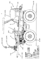
まず、図1、図2を用いて、本実施の形態の乗用管理機1についてその概略構成を説明する。
First, with reference to FIG. 1 and FIG. 2, a schematic configuration of the
図1は、本実施の形態における乗用管理機1の左側面図であり、図2は、本実施の形態における乗用管理機1の正面図である。
FIG. 1 is a left side view of the
尚、図1は、後述する左右一対の施肥ブーム110L、110Rが、走行車体2の側方に沿った収納状態に位置する場合を示す。
1 shows a case where a pair of left and
また、図2は、左右一対の施肥ブーム110L、110Rの内、左側の施肥ブーム110Lが、走行車体2の左方向に突き出した施肥作業を行う作業状態に位置する場合を示すとともに、右側の施肥ブーム110Rは図示を省略した。
Moreover, FIG. 2 shows the case where the
なお、以下の説明では、前後方向とは、乗用管理機1の前後方向である。さらに言えば、前後方向とは、この乗用管理機1が直進する際の進行方向であり、進行方向前方側を前後方向前側、後方側を前後方向後側という。乗用管理機1の進行方向とは、乗用管理機1の直進時において、乗用管理機1の操縦席6からハンドル7に向かう方向であり、ハンドル7側が前側、操縦席6が後側となる。また、車幅方向とは、当該前後方向に対して水平に直交する方向である。ここでは、前後方向前側を視た状態で右側を車幅方向右側、前後方向前側を視た状態で左側を車幅方向左側という。さらに、鉛直方向とは、前後方向と車幅方向とに直交する方向である。これら前後方向、車幅方向及び鉛直方向は、互いに直交する。
In the following description, the front-rear direction is the front-rear direction of the
図1、図2に示す通り、本実施の形態の乗用管理機1の走行車体2には左右一対の前輪3L、3Rと左右一対の後輪4L、4Rが設けられている。
As shown in FIGS. 1 and 2, the traveling
また、走行車体2の後部には施肥装置100が設けられており、走行車体2の前部には、左右一対の生育診断センサ410L、410Rを上下に移動可能な昇降リンク機構200が設けられている。
Further, a
尚、本実施の形態では、左右一対の生育診断センサ410L、410Rの高さ調整を行う為の昇降リンク機構200、及びセンシング角度の変更を行う為の後述する左右一対のセンシング角度変更機構500L、500R等は、薬液等を散布する防除作業機に用いられるセンターブームとサイドブームを昇降させる為の昇降リンク機構や、サイドブームを散布作業位置や収納位置に移動させるサイドブーム開閉機構を利用した場合について説明するが、これに限定されるものではない。
In this embodiment, a
また、走行車体2の左右一対の前輪3Lと3Rの間の上方には、ボンネット5で覆われたエンジン(図示省略)が搭載されている。また、走行車体2の中央部には操縦席6が設けられており、操縦席6の前方にはハンドル7が設けられている。
An engine (not shown) covered with a
ハンドル7を左右に操舵すると、左右一対の前輪3L、3R及び左右一対の後輪4L、4Rが同時に連動して操舵され、小回り走行のできる四輪操舵構成としている。
When the
また、上述した施肥装置100は、操縦席6の背後に配置された散布用の粒状肥料を貯留する為の左右一対のタンク101L、101Rと、粒状肥料を繰り出す為に当該タンク101L、101Rの下部にそれぞれ配置された左右一対の繰出装置102L、102R(図8参照)と、当該繰出装置により繰り出された粒状肥料を送風装置103からの気流に乗せて移送する為の左右一対の移送管(図示省略)と、当該左右一対の移送管に蛇腹管(図示省略)を介して回動自在に配置された左右一対の施肥ブーム110L、110Rと、当該施肥ブーム110L、110Rを、走行車体2の側方に沿った収納状態の位置と走行車体2の左右方向に突き出した施肥作業状態の位置との間を回動自在に移動させる左右一対の開閉油圧シリンダ120L、120R(図8参照)等から構成されている。また、左右一対の施肥ブーム110L、110Rには、粒状肥料を圃場に散布する為に、所定間隔毎に一定口径の肥料噴出口111が設けられている。
Further, the
次に、主として図3〜図7を用いて、本実施の形態の乗用管理機1の構成について更に詳細に説明する。
Next, the configuration of the
図3は、本実施の形態の乗用管理機1の前部を拡大した右側面図であり、図4は、本実施の形態の乗用管理機1に搭載したGPSアンテナ310を示す斜視図である。
FIG. 3 is an enlarged right side view of the front portion of the
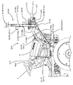
図5は、本実施の形態の乗用管理機1の左側の生育診断センサ410Lのセンシング角度を変更可能にする左側センシング角度変更機構500Lを説明する為の概略斜視図である。
FIG. 5 is a schematic perspective view for explaining a left-side sensing
図6(a)は乗用管理機1における左側の生育診断センサ410Lの取り付け方法を説明する為の分解概略斜視図であり、図6(b)は図6(a)で示した左側の生育診断センサ410Lを設置するためのセンサ用台座430の可動部を説明する為の部分拡大側面図であり、図6(c)は図6(a)で示した左側センサ搭載ステー組品420Lを左側支柱320Lに固定した状態を説明する為の要部を示す左側面図である。
6A is an exploded schematic perspective view for explaining a method of attaching the left growth
図7は、本実施の形態の乗用管理機1のハンドル7の周辺を右後方から見た斜視図である。
FIG. 7 is a perspective view of the periphery of the
本実施の形態の乗用管理機1の昇降リンク機構200は、図2、図3に示す通り、ボンネット5の左右両側に配置された左右一対の平行リンク210L、210Rと、左右一対の昇降油圧シリンダ220L、220R等を備えている。
The
また、当該右側の平行リンク210Rは、図3に示す通り、右側の上側リンク210Raと下側リンク210Rbと、これら右側の上側リンク210Ra及び下側リンク210Rbの後端部を所定間隔を隔てて回動可能に連結すると共に走行車体2の右側(車幅方向右側)に下端部が固定された右リンク第1連結部材211Rと、これら右側の上側リンク210Ra及び下側リンク210Rbの前端部を所定間隔を隔てて回動可能に連結する右リンク第2連結部材212Rとを備えている。
Further, as shown in FIG. 3, the right
また、当該左側の平行リンク210Lは、左側の上側リンク210Laと下側リンク210Lbと、これら左側の上側リンク210La及び下側リンク210Lbの後端部を所定間隔を隔てて回動可能に連結すると共に走行車体2の左側(車幅方向左側)に下端部が固定された左リンク第1連結部材211Lと、これら左側の上側リンク210La及び下側リンク210Lbの前端部を所定間隔を隔てて回動可能に連結する左リンク第2連結部材212Lとを備えている。
The left
また、右側の昇降油圧シリンダ220Rの下端部は、図3に示す通り、右リンク第1連結部材211Rの下端部に回動可能に固定されると共に、右側の昇降油圧シリンダ220Rの伸縮側の先端部221Rは、右側の上側リンク210Raの中央部に回動可能に固定されている。
Further, as shown in FIG. 3, the lower end of the right elevating
また、左側の昇降油圧シリンダ220Lの下端部は、左リンク第1連結部材211Lの下端部に回動可能に固定されると共に、左側の昇降油圧シリンダ220Lの伸縮側の先端部221Lは、左側の上側リンク210Laの中央部に回動可能に固定されている。
Further, the lower end portion of the left elevating
また、左第2連結部材212Lと右第2連結部材212Rは、所定間隔を隔てて上端部において上端連結パイプ213により連結されている(図2、図5参照)。
The left second connecting
また、左第2連結部材212Lの前側面の下端側と右第2連結部材212Rの前側面の下端側には、上述した左側の平行リンク210Lと右側の平行リンク210Rとの左右の幅より長く、概ね前輪3の輪間距離(トレッド)程度の長さを有するフロント水平支柱330(図2、図3、図5参照)が溶接固定されている。
Further, the lower side of the front side surface of the second
また、図3、図5に示す通り、フロント水平支柱330の前側には、センターブーム331が平行に固定されており、当該センターブーム331の中央部、即ち、乗用管理機1の左右方向の幅の中央位置には、GPSアンテナ310を搭載する為のGPSアンテナ用台座311が着脱自在に後付されており、当該GPSアンテナ用台座311の上面にGPSアンテナ310が固定されている。
Further, as shown in FIGS. 3 and 5, a
尚、センターブーム331は、薬剤散布用ノズルを防除作業機の前側に所定間隔で取り付ける為にフロント水平支柱330に固定部材332(図5参照)を介して固定されたパイプ状部材であるが、本実施の形態では、薬剤散布用ノズルは不要であるので装着していない。
The
本実施の形態の乗用管理機1では、後述する制御回路部700に内蔵されている位置情報取得部710(図8参照)は、GPS(Global Positioning System)を用いることにより地球上での乗用管理機1の位置情報(即ち、座標情報)を取得する構成であり、複数の人工衛星からの信号をそれぞれ所定間隔で受信する為のGPSアンテナ310を備え、位置情報取得部710により取得された位置情報は、左右一対の生育診断センサ410L、410Rにより取得された育成物の生育状況と対応づけてメモリ部720(図8参照)に記録可能に構成されている。位置情報及び生育状況の記録については、更に後述する。
In the
本実施の形態では、生育診断センサ410L、410Rとして、公知の植物生育度診断装置、土壌肥沃度診断装置、肥料濃度検出装置などを用いた場合について説明するが、これに限定されるものではない。例えば、生育診断センサ410L、410Rにおいて、異なる波長の二つのレーザ光を育成物に照射し、その育成物からの反射光の差異を計測して、当該育成物の窒素含有量を算出することで、当該育成物の生育状況を判定する構成であっても良い。
In the present embodiment, a case where a known plant growth diagnostic device, soil fertility diagnostic device, fertilizer concentration detection device, or the like is used as the growth
また、GPSアンテナ310の信号線310aは、図3に示す通り、右側の下側リンク210Rbに沿って配線され、コントローラ610に収納された制御回路部700に接続されている。
Further, as shown in FIG. 3, the
尚、コントローラ610は、図7に示す通り、ハンドル7の下方に配置されたメータパネル600の右側に設けられており、表示装置620を備えている。
As shown in FIG. 7, the
上記構成により、左右一対の昇降油圧シリンダ220L、220Rの先端部221L、221Rの伸縮の度合いを、制御回路部700からの制御信号により調整することで、左右一対の生育診断センサ410L、410Rの高さを変更することが出来る。
With the above configuration, the degree of expansion / contraction of the
次に、図5を用いて、本実施の形態の乗用管理機1の左側センシング角度変更機構500Lについて説明する。
Next, the left-side sensing
尚、右側の生育診断センサ410R(図2参照)のセンシング角度を変更可能にする右側センシング角度変更機構500R(図2参照)は、左側センシング角度変更機構500Lと左右対称の同じ構成であるので説明を省略する。
The right-side sensing
また、左側の生育診断センサ410Lは、図2に示す通り、左側支柱320Lに取り付けられた左側センサ搭載ステー組品420Lの上端に配置されているが、この構成については図6を用いて更に後述する。
Further, as shown in FIG. 2, the left
また、図5では、左側支柱320Lに左側センサ搭載ステー組品420Lが取り付けられていない状態を示している。
FIG. 5 shows a state where the left sensor mounting
本実施の形態の乗用管理機1の左側センシング角度変更機構500Lは、図5に示す通り、フロント水平支柱330の左端に回動ピン501を中心として回動自在に連結されると共に正面視で略コの字状の左側コーナープレート510Lと、図5に示された左側コーナープレート510Lの後側に垂直に固定された左側支柱320Lと、左側コーナープレート510Lを回動させる左側の回動油圧シリンダ520L等を備えている。
As shown in FIG. 5, the left sensing angle changing mechanism 500 </ b> L of the
また、左側の回動油圧シリンダ520Lは、根本側の端部521Lが、左リンク第2連結部材212Lに取り付けられた支持ピン530により回動自在に連結されると共に、伸縮側の先端部522Lが、図5に示された左側コーナープレート510Lの端部に立設された連結ピン540により回動自在に連結されている。連結ピン540の上端部に設けられた貫通孔には抜け止め用ピン541が装着されている。
Further, the left-side rotating
また、左右一対の左側支柱320L及び右側支柱320Rの上端の両側面には、図示しない左右一対のサイドブーム傾斜用油圧シリンダの一端側を回動可能に連結する為の連結プレート321L、321Rが溶接固定されている。
Also,
尚、防除作業機においては、図示しない左右一対のサイドブームの前端部が、左右一対の左側支柱320L及び右側支柱320Rの下端部に回動可能に連結されると共に、それら左右一対のサイドブームの前端部から後方に少し離れた位置に、左右一対のサイドブーム傾斜用油圧シリンダの他端側が回動可能に連結されることにより、左右一対のサイドブームを収納する時に、後端側を斜め上方に向けて傾斜させる構成であるが、本実施の形態では、当該左右一対のサイドブーム及び左右一対のサイドブーム傾斜用油圧シリンダは不要であるので装着していない。
In the control work machine, the front end portions of a pair of left and right side booms (not shown) are rotatably connected to the lower end portions of the left and right pair of left and
上記の構成により、左側の回動油圧シリンダ520Lの先端部522Lが矢印Aの方向に移動すると、左側コーナープレート510Lは、回動ピン501を中心として、平面視で時計回り(図5の矢印R参照)に回動することにより、左側支柱320Lが平面視で時計回り(図5の矢印R参照)に回動する。 また、左側の回動油圧シリンダ520Lの先端部522Lが矢印Bの方向に移動すると、左側コーナープレート510Lは、回動ピン501を中心として、平面視で反時計回り(図5の矢印L参照)に回動することにより、左側支柱320Lが平面視で反時計回り(図5の矢印L参照)に回動する。
With the above configuration, when the
これにより、左側の回動油圧シリンダ520Lの先端部522Lの伸縮の度合いを、後述する制御回路部700からの制御信号により調整することで、左側支柱320Lに取り付けられた左側センサ搭載ステー組品420Lの上端に配置された左側の生育診断センサ410Lのセンシング角度を変更することが出来る。
Accordingly, the left sensor mounted
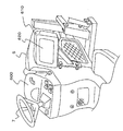
次に、図6(a)〜図6(c)を用いて、本実施の形態の乗用管理機1の左側センサ搭載ステー組品420Lの構成を中心に説明すると共に、左側の生育診断センサ410Lの取り付け方法を説明する。
Next, with reference to FIGS. 6A to 6C, the configuration of the left sensor-mounted
尚、右側の生育診断センサ410R(図2参照)のセンシング角度を変更可能にする右側センサ搭載ステー組品420R(図2参照)は、左側センサ搭載ステー組品420Lと同じ構成であるので説明を省略する。
The right sensor-equipped
左側センサ搭載ステー組品420Lは、図6(a)に示す通り、左側支柱320Lの先端部に着脱可能に構成されたセンサ用台座430と、左側の生育診断センサ410Lを上面中央位置に固定する為の平面視で円形状のセンサ固定プレート440とから構成されている。
As shown in FIG. 6A, the left sensor mounting
更に、センサ用台座430は、左側支柱320Lの先端部に予め固定されている連結プレート321Lを利用することでセンサ用台座430を左側支柱320Lに着脱可能に固定する台座固定用部材450と、連結プレート321Lが突き出した方向と同じ方向で且つ水平方向に伸びた軸芯を有する回動支持ピン461を介して台座固定用部材450の上端部において回動可能(回動方向について、図6(a)の矢印P及び矢印Q参照)に支持されると共に位置調整用ボルト462a及び蝶ナット462b(図6(b)参照)により位置決めされ固定されるセンサ固定プレート受け台460とから構成されている。
Furthermore, the
更にまた、台座固定用部材450は、断面が略コの字状に曲げられた第1板状部材451の上端側を、断面が略コの字状に曲げられた第2板状部材452の下端側により外側から取り囲むと共にその重なり部分において溶接により連結固定されて形成された下固定部450aと、第2板状部材452の上端縁部に溶接固定された断面が四角形状の筒状部材であって、回動支持ピン461を貫通させる為の上貫通孔450b1及びその下方に位置調整用ボルト462aを貫通させる為の下貫通孔450b2が形成された上固定部450bと、下固定部450aの断面が略コの字状を成す対向する内壁面により形成された空間部分Sに左側支柱320Lの先端部を嵌合収納させると共に(図6(c)参照)、下固定部450aの両側面の上下2箇所に固定されたねじ溝付きピン453を介してダブルナット453aを締め付けて固定する為の固定プレート450cとから構成されている。
Furthermore, the
ここで、空間部分Sについて更に説明すると、第1板状部材451の対向する内壁面間(図6(a)の寸法W1aの部分)が、左側支柱320Lの幅部分(図6(a)の寸法W1bの部分)と嵌合し、且つ第2板状部材452の対向する内壁面間(図6(a)の寸法W2aの部分)が、左側支柱320Lの連結プレート321Lを含む幅部分(図6(a)の寸法W2bの部分)と嵌合した構成である。尚、W2a>W2b>W1a>W1bである。
Here, the space portion S will be further described. Between the opposing inner wall surfaces of the first plate-like member 451 (the portion of the dimension W1a in FIG. 6A), the width portion of the
また、第1板状部材451における空間部分Sの奥行き寸法Daと、左側支柱320Lの対応する部分の寸法Db(図6(a)参照)は、Db≧Daの関係にある。
Further, the depth dimension Da of the space portion S in the first plate-
また、センサ固定プレート受け台460は、上固定部450bと同じ断面形状を有する筒状部材であって、対向する両側面の下端側にそれぞれ逆扇形状の連結板463、463が下方に突き出して固定された受け台支持部460aと、当該受け台支持部460aの上端縁部に溶接固定された平面視で円形状の受け台460bと、上述した回動支持ピン461、位置調整用ボルト462a及び蝶ナット462b(図6(b)参照)とから構成されている。
The sensor fixing
また、逆扇形状の連結板463には、回動支持ピン461を挿入する為の貫通孔463aと、位置調整用ボルト462aを挿入すると共に回動支持ピン461を中心として逆扇形状の連結板463を回動可能にする為の円弧状の長孔463bが形成されている。
Further, the reverse fan-shaped connecting
また、受け台460bの外径はセンサ固定プレート440の外径と同じであり、その外周近傍には6つの貫通孔464が等間隔で設けられている。
The outer diameter of the
一方、センサ固定プレート440の外周近傍には、受け台460bに設けられた隣接する2つの貫通孔464のそれぞれの位置に対応する位置を円弧の両端とする円弧状の長孔442が等間隔で3つ形成されている。
On the other hand, in the vicinity of the outer periphery of the
以上の構成において、主として図6(a)を参照しながら、左側の生育診断センサ410Lを取り付ける手順を説明する。
In the above configuration, a procedure for attaching the left
まず、左側支柱320Lの上端部に対して、センサ固定プレート受け台460が取り付けられた台座固定用部材450における空間部分Sを位置合わせして(図6(a)の二点鎖線で示した矢印F参照)、図6(c)に示す通りダブルナット453aを用いて固定プレート450cで固定する。
First, the space portion S in the
次に、左側の生育診断センサ410Lが上面中央位置に固定されたセンサ固定プレート440を受け台460b上に載せて、3本の位置決め用ボルト441を3つの円弧状の長孔442に1本ずつ挿入すると共に、受け台460bに設けられた貫通孔464に1つおきの等間隔で嵌合させて、矢印Eで示す方向に回動させながら任意の位置で位置決めして固定する。
Next, the
最後に、位置調整用ボルト462a又は蝶ナット462b(図6(b)参照)を緩めて、受け台460bを矢印P方向又は矢印Q方向に回動させることにより、左側の生育診断センサ410Lの取付面の上下方向への傾斜角度(仰角、伏角)を調整し、任意の位置で位置決めして固定する。
Finally, the
尚、左側の生育診断センサ410Lの信号線410La(図3参照)は、左側センサ搭載ステー組品420Lに沿って配線され、更に左側の下側リンク210Lbに沿って配線されて制御回路部700に接続されている。また、右側の生育診断センサ410Rの信号線410Ra(図3参照)は、右側センサ搭載ステー組品420Rに沿って配線され、更に右側の下側リンク210Rbに沿って配線されて制御回路部700に接続されている。
The signal line 410La (see FIG. 3) of the left
以上のことから、本実施の形態の乗用管理機1によれば、左側支柱320Lの上端部及び右側支柱320Rに対して、左側センサ搭載ステー組品420L及び右側センサ搭載ステー組品420Rを後付けで確実に固定することが出来る。
From the above, according to the
また、左右一対の左側の生育診断センサ410L及び右側の生育診断センサ410Rは、矢印E方向(図6(a)参照)の回動による位置調整と、矢印P及びQ方向(図6(a)参照)の回動による位置調整が、手動によりそれぞれ独立して行うことが出来る。
The left and right pair of growth
尚、本実施の形態のGPSアンテナ310及び位置情報取得部710を包括する構成は、本発明の位置情報取得装置の一例にあたる。また、本実施の形態の左側の生育診断センサ410Lは、本発明の生育状況検知装置の一例にあたり、また、本発明の左側配置センサ(図2の符号410L−1参照)によって例えば走行車体の左右幅方向(車幅方向)を基準とした中央位置から左側における育成物の生育状況を検知する構成の一例にあたり、また、本発明の左側測定センサ(図2の符号410L−2参照)を走行車体2の左側(車幅方向左側)に配置した構成の一例にあたる。また、本実施の形態の右側の生育診断センサ410Rは、本発明の生育状況検知装置の一例にあたり、また、本発明の右側配置センサ(図2の符号410R−1参照)によって例えば走行車体の左右幅方向を基準とした中央位置から右側における育成物の生育状況を検知する構成の一例にあたり、また、本発明の右側測定センサ(図2の符号410R−2参照)を走行車体2の右側(車幅方向右側)に配置した構成の一例にあたる。また、本実施の形態の制御回路部700は、本発明の制御装置の一例にあたる。また、本実施の形態の昇降リンク機構200は、本発明の昇降機構の一例にあたり、本実施の形態の施肥装置100は、本発明の施肥装置の一例にあたる。また、本実施の形態の左右一対の施肥ブーム110L、110Rは、本発明の肥料噴出アームの一例にあたる。
The configuration including the
次に、本実施の形態の乗用管理機1の動作について、主として図8を用いて説明する。
Next, the operation of the
図8は、本実施の形態の乗用管理機1の主な制御構成を示すブロック図である。
FIG. 8 is a block diagram illustrating a main control configuration of the
ここでは、水稲栽培において、追肥を実施する場面について説明する。 Here, a scene where top dressing is performed in paddy rice cultivation will be described.
操縦席6の作業者は、乗用管理機1の左施肥ブーム開閉レバー及び右施肥ブーム開閉レバー(図示省略)を独立して操作することにより、乗用管理機1の左右に配置された左側の施肥ブーム110Lと、右側の施肥ブーム110Rを収納状態の位置から作業状態の位置に移動させる。
The operator of the cockpit seat 6 operates the left fertilizer boom opening / closing lever and the right fertilization boom opening / closing lever (not shown) of the
尚、左側の施肥ブーム110Lと右側の施肥ブーム110Rの移動角度(折り畳み角度)は、それぞれ独立して操作可能であり、当該移動角度に応じた散布量制御が可能に構成されている。即ち、前記移動角度を変更した場合は、単位面積当たりの散布量が多くなってしまうので、散布量を調整する必要がある。
In addition, the movement angle (folding angle) of the
具体的には、作業者の左施肥ブーム開閉レバー及び右施肥ブーム開閉レバー(図示省略)の独立した操作により、その操作量に応じて、制御回路部700(図8参照)から左側開閉油圧シリンダ120L及び右側開閉油圧シリンダ120Rにそれぞれ制御信号が送信される。
More specifically, the left open / close hydraulic cylinder is operated from the control circuit unit 700 (see FIG. 8) according to the operation amount by the operator's independent operation of the left fertilizer boom open / close lever and the right fertilizer boom open / close lever (not shown). Control signals are transmitted to 120L and the right opening / closing
また、作業者による昇降操作レバー(図示省略)の操作により、昇降リンク機構200を昇降させて、左右一対の生育診断センサ410L、410Rの高さを調整する。
Further, the height of the pair of left and right
具体的には、作業者による昇降操作レバー(図示省略)の操作により、制御回路部700(図8参照)から左側昇降油圧シリンダ220L及び右側昇降油圧シリンダ220Rに同時に制御信号が送信される。
Specifically, the control signal is simultaneously transmitted from the control circuit unit 700 (see FIG. 8) to the left lifting
尚、左側の生育診断センサ410L及び右側の生育診断センサ410Rは、必要に応じて矢印E方向(図6(a)参照)の回動による位置調整と、矢印P及びQ方向(図6(a)参照)の回動による位置調整が可能であることは上述した通りである。
The left
また、作業者による左側センシング角度変更レバー及び右側センシング角度変更レバー(図示省略)の独立した操作により、左側の生育診断センサ410Lが搭載された左側センサ搭載ステー組品420L、及び右側の生育診断センサ410Rが搭載された右側センサ搭載ステー組品420Rが概ね90度の範囲で回動し(図5の矢印L、矢印R参照)、任意の角度で停止させることが可能である。
Also, the left sensor mounted
具体的には、作業者による左側センシング角度変更レバー及び右側センシング角度変更レバー(図示省略)の独立した操作により、その操作量に応じて、制御回路部700(図8参照)から左側回動油圧シリンダ520L及び右側回動油圧シリンダ520Rにそれぞれ制御信号が送信されると、左側の生育診断センサ410L及び右側の生育診断センサ410Rは、その操作量に応じた所定角度だけそれぞれ独立に回動した後に停止する。また、左側回動油圧シリンダ520L及び右側回動油圧シリンダ520Rを作動させて微調整ができる。
Specifically, by the independent operation of the left sensing angle change lever and the right sensing angle change lever (not shown) by the operator, the left turning hydraulic pressure is controlled from the control circuit unit 700 (see FIG. 8) according to the operation amount. When a control signal is transmitted to each of the
尚、本実施の形態の左側回動油圧シリンダ520L及び右側回動油圧シリンダ520Rは、本発明の回動機構の一例にあたる。また、本実施の形態の左側回動油圧シリンダ520Lは、本発明の左側測定センサ回動機構の一例にあたり、本実施の形態の右側回動油圧シリンダ520Rは、本発明の右側測定センサ回動機構の一例にあたる。
Note that the left turning
次に、乗用管理機1が圃場内での運転を開始すると、GPSアンテナ310により受診された人工衛星からの信号が、制御回路部700の位置情報取得部710に送られて、乗用管理機1の位置情報が取得される。
Next, when the
一方、左側の生育診断センサ410Lは、乗用管理機1の左右幅方向を基準として概ね左側の育成物の生育状況を検知し検知結果を制御回路部700に送信すると共に、右側の生育診断センサ410Rは、乗用管理機1の左右幅方向を基準として概ね右側の育成物の生育状況を検知し検知結果を制御回路部700に送信する。
On the other hand, the left growth
制御回路部700は、位置情報取得部710により得られた乗用管理機1の位置情報と、その位置情報に対応して得られた左側の生育診断センサ410L及び右側の生育診断センサ410Rによる育成物の生育状況の検知結果とを対応づけてメモリ部720に記憶させる。
The
ここで、制御回路部700における、乗用管理機1の位置情報と、育成物の生育状況の検知結果との対応づけについて、一例を説明する。
Here, an example of the correspondence between the position information of the
例えば、左側の生育診断センサ410Lが検知する検知領域を撮像した画像データを取得した場合、その時の左側の生育診断センサ410Lの地面からの高さとセンサの方向(仰角、伏角を含む)などの情報を利用して、検知対象である育成物の、撮像画像の座標系における位置座標(x、y、z)を、予め定められたルールに基づいて、左側の生育診断センサ410Lの位置を原点とする座標系における位置座標(x'、y’、z’)に変換する。
For example, when image data obtained by imaging a detection region detected by the left growth
一方、その時に、GPSアンテナ310により取得された、GPS側位のために用いられる座標系における位置座標と、左側の生育診断センサ410Lの位置を原点とする座標系におけるGPSアンテナ310の位置座標とを用いて、検知対象の育成物の位置座標(x'、y’、z’)を、GPS側位のために用いられる座標系における位置座標(X、Y、Z)に変換する。
On the other hand, at that time, the position coordinates in the coordinate system used for the GPS side position acquired by the
上記により取得された検知対象の育成物の位置座標(X、Y、Z)と、撮像画像の座標系における検知対象の育成物の位置座標(x、y、z)での育成物の生育状況の検知結果とを対応づける。 The growth state of the grown object at the position coordinates (X, Y, Z) of the detected object grown object and the position coordinates (x, y, z) of the detected object object grown object in the coordinate system of the captured image. Are associated with the detection results.
これにより、制御回路部700において、育成物の生育状況の検知結果が、GPS側位のために用いられる座標系における位置座標(X、Y、Z)と対応づけられるので、制御回路部700は、育成物の生育状況を検知しながら、予めメモリ部720に格納されている判定基準となる生育状況のデータと比較して、育成物の生育状況の検知結果の良否レベルを判定し、当該判定結果をメモリ部720に逐次格納する。圃場全体において、上記処理を繰り返すことにより、圃場における育成物の生育状況のマップデータが取得出来、その判定結果に応じて制御回路部700により色分けされたマップデータが表示装置620に表示される。
Thereby, in the
また、制御回路部700は、左側の生育診断センサ410L及び右側の生育診断センサ410Rによる育成物の生育状況の検知結果と、予め格納されているデータベース(図示省略)とに基づいて、当該育成物の左側の生育状況及び右側の生育状況の良否レベルをそれぞれ判定すると共に、それぞれの良否レベルに応じた適切な左側及び右側の追肥の散布量をリアルタイムで設定する。
In addition, the
例えば、左側の育成物の生育状況の良否レベルが良好と判定され、右側の育成物の生育状況の良否レベルが悪いと判定された場合は、左側に対する追肥の散布量を最小限又はゼロに設定し、右側に対する追肥の散布量を標準値より多く設定する。 For example, if the quality level of the left growth is determined to be good and the quality level of the right growth is determined to be poor, the amount of additional fertilizer applied to the left side is set to minimum or zero Then, set the amount of additional fertilizer applied to the right side higher than the standard value.
また、上記データベースには、例えば、育成物の種類毎に、生育診断センサによる検知結果とその育成物の生育状況の良否レベルとの対応関係を表したデータと、その良否レベルに応じた適切な追肥の散布量が予め記録されている。 In addition, in the database, for example, for each type of the grown product, data representing the correspondence between the detection result by the growth diagnosis sensor and the quality level of the grown state of the grown product, and appropriate data according to the quality level The amount of topdressing application is recorded in advance.
また、当該データベースは、メモリ部720に予め格納された構成であっても良いし、制御回路部700に内蔵された通信部(図示省略)によりインターネットを介して所定のサーバ(図示省略)からダウンロードして取得する構成であっても良い。
The database may be stored in advance in the
そして、制御回路部700は、設定した左側及び右側のそれぞれの散布量に応じて、左側の繰出装置102L及び右側の繰出装置102Rによる粒状肥料の繰出量、及び送風装置103による送風量を決定する。
Then, the
尚、表示装置620には、散布に関する設定とその結果が表示される。
The
また、メモリ部720に記憶された、乗用管理機1の位置情報と生育状況の検知結果とを対応づけたデータや育成物の生育状況の検知結果の良否レベルを色分けしたマップデータなどは、制御回路部700に内蔵された通信部(図示省略)によりインターネットを介して所定のサーバ(図示省略)にアップロード可能に構成されていても良い。これにより、サーバにアップロードされた当該データを所定のコンピュータにダウンロードすることで、育成物の生育状況とその位置情報を正確に確認出来る。
Further, the data stored in the
尚、メモリ部720に記憶された、乗用管理機1の位置情報と生育状況の検知結果とを対応づけたデータや、育成物の生育状況の検知結果の良否レベルを色分けしたデータなどを、半導体メモリ等を用いた補助記憶装置(USBメモリ等)に記録して、簡単に持ち運び出来る様にする、USB接続口(図示省略)を制御回路部700に予め設けておいても良い。また、USB接続口は、前記表示装置620自体やその近傍に構成することで、使い易くなる。
It should be noted that the data stored in the
また、表示装置620は機体に対して着脱自在であり、タブレットやスマートフォンなどのように持ち運びできる構成としてもよく、この場合、表示装置620自体の中の記憶装置に検知結果を記憶させる構成としてもよい。
In addition, the
本実施の形態の乗用管理機1によれば、左右一対の生育診断センサ410L、410Rによる育成物の生育状況を検知して、その検知結果に応じて、リアルタイムで追肥の散布量を制御することが出来る。
According to the
これにより、育成物に対する過剰な施肥を防止すると共に、圃場内の育成物の生育のばらつきを均一化出来るので、施肥量の低減を図れると同時に収量の向上を図ることが出来る。 Thereby, while preventing the excessive fertilization with respect to a grown material, since the dispersion | variation in the growth of the grown material in a field can be equalized, the amount of fertilization can be reduced and the yield can be improved.
また、上記実施の形態では、左右一対の生育診断センサ410L、410Rによる育成物の生育状況を検知して、その検知結果に応じて、リアルタイムで追肥の散布量を制御する構成について説明したが、この結果を後日利用するようにしてもよい。また、前述のようなリアルタイムで追肥する場合に限らず例えば、圃場全体について、左右一対の生育診断センサ410L、410Rによる育成物の生育状況の検知のみ行って、圃場全体における育成物の生育状況の検知結果の良否レベルを色分けしたマップデータを作成した後、そのマップデータを表示装置620に表示させながら、検知結果に応じて、追肥の散布量を制御する構成としても良い。
Moreover, although the said embodiment demonstrated the structure which detects the growth condition of the grown material by a pair of right and left growth
また、上記実施の形態では、左右一対の生育診断センサ410L、410Rによる育成物の生育状況を検知して、その検知結果に応じて、リアルタイムで追肥の散布量を制御する構成について説明したが、これに限らず例えば、圃場全体について、左右一対の生育診断センサ410L、410Rによる育成物の生育状況の検知のみ行って、圃場全体における育成物の生育状況の検知結果の良否レベルを色分けしたマップデータを作成した後、補助記憶装置等に記憶しておき、次年度において、同じ圃場の育成物に対して、そのマップデータを表示装置620に表示させながら、前年度の検知結果に応じて、追肥の散布量を制御する構成としても良い。また、移植機や田植機等で移植作業を行うときにおいて施肥作業を行うことがあるが、次年度の移植作業時に前記マップデータを利用して施肥量制御を行うように構成してもよい。この場合、USBメモリ等を移植機や田植機等に装着可能にしたり、乗用管理機1から取り外した表示装置620を移植機や田植機等に装着可能に構成しておく。
Moreover, although the said embodiment demonstrated the structure which detects the growth condition of the grown material by a pair of right and left growth
尚、上述した制御回路部700における、乗用管理機1の位置情報と育成物の生育状況の検知結果との対応づけや、マップデータの利用などについて、上記と一部重複するが、別の例を用いて以下に具体的に説明する。
In the
1.GPSアンテナ310と左右一対の生育診断センサ410L、410Rと施肥装置100の対応づけについて:
GPSアンテナ310は1秒毎に受信(変更可能)する。
1. Regarding the correspondence between the
The
また、左右一対の生育診断センサ410L、410Rは0.1秒毎に側定(変更可能)する。
Also, the pair of left and right
図10(a)、図10(b)を用いて、GPSアンテナ310と左右一対の生育診断センサ410L、410Rと施肥装置100の対応づけについて説明する。
The correspondence between the
図10(a)において、AはGPSアンテナ310の現在位置、Bは1秒後の位置を示す。図10(a)は、本実施の形態の乗用管理機1と、右側の生育診断センサ410Rの生育状況検出領域との関係を示す模式図であり、図10(b)は、右側の生育診断センサ410Rによる、生育状況検出領域を説明するための模式図である。
In FIG. 10A, A indicates the current position of the
Aの位置において、GPSアンテナ310の受信中心位置を原点P0とする。
At the position A, the reception center position of the
1秒後のBの位置において、GPSアンテナ310の受信中心位置を原点P1とする。
At the position B after 1 second, the reception center position of the
以下においては右側の生育診断センサ410Rの検知について説明し、左側の生育診断センサ410Lの検知については同じフローなので省略する。
Hereinafter, detection of the right
また、ここでの説明は、GPSアンテナの位置や左右一対の生育診断センサ410L、410Rの位置に関わらず適用できる。
The description here can be applied regardless of the position of the GPS antenna and the positions of the pair of left and right growth
Aの位置を開始点として、右側の生育診断センサ410Rによる、0秒後から0.1秒後の生育状況検出領域は、図10(b)に示す通り、点SAL0、点SAR0、点SAL1、点SAR1で囲まれる領域となる。
As shown in FIG. 10 (b), the growth status detection area from 0 seconds to 0.1 seconds by the right
点SAL0、点SAR0、点SAL1、点SAR1の位置は、GPSアンテナ310で検出したP0の緯度、経度から算出し、この4点で囲まれる領域と同時に検出した生育状況とを一致させて(対応づけて)記憶する。
The positions of point SAL0, point SAR0, point SAL1, and point SAR1 are calculated from the latitude and longitude of P0 detected by the
続けて、0.1秒毎に検出を継続し、0.9秒後から1秒後の生育状況検出領域は、点SAL9、点SAR9、点SAL10、点SAR10で囲まれる領域となる。点SAL9、点SAR9、点SAL10、点SAR10の位置は、GPSアンテナ310で検出したP0の緯度、経度から算出し、この4点で囲まれる領域と同時に検出した生育状況とを一致させて(対応づけて)記憶する。
Subsequently, the detection is continued every 0.1 second, and the growth state detection region from 0.9 second to 1 second later is a region surrounded by the points SAL9, SAR9, SAL10, and SAR10. The positions of the points SAL9, SAR9, SAL10, and SAR10 are calculated from the latitude and longitude of P0 detected by the
これにより、Aの位置からBの位置に移動する間(1秒間)に、10個の領域を測定することになり、それぞれの領域に生育状況が存在する(10個の生育状況)。 Thus, 10 areas are measured while moving from the position A to the position B (1 second), and there are growth conditions in each area (10 growth conditions).
尚、0.1秒間に検出される生育状況は、ほとんど同じであるが、複数の生育状況が検出された場合、面積が一番広い生育状況とする。 In addition, although the growth condition detected in 0.1 second is almost the same, when a plurality of growth conditions are detected, the growth condition having the largest area is set.
10個の生育状況を平均して、1秒間に走行した領域SA(点SAL0、点SAR0、点SAL10、点SAR10)の領域の生育状況とする。予め記憶している生育状況と色から、平均して算出した生育状況に対して色を付与して記憶させる。これにより、領域SAの生育状況が決定する。 Ten growth conditions are averaged to obtain the growth condition of the area SA (point SAL0, point SAR0, point SAL10, point SAR10) that has traveled in one second. A color is assigned to the growth status calculated on average from the growth status and color stored in advance, and stored. Thereby, the growth condition of area | region SA is determined.
次いで、Bの位置を原点P1として、上記の領域SAで行ったのと同じ処理を領域SBにおいて繰り返す。 Next, the same processing as that performed in the area SA is repeated in the area SB with the position B as the origin P1.
これにより、生育状況マップが完成する。 Thereby, a growth situation map is completed.
2.マップの補正について:
GPSアンテナ310の受信状況により、位置がずれるので、メモリ部720に予め記憶させている地図データと、作成したマップとを照合させる。例えば、圃場の横に存在する畦や道路に対して生育状況マップが割り当てられると、表示装置620に表示した時に見づらく、正確な作業の遂行を妨げるおそれがあるので、作成した生育状況マップを圃場側にずらす構成とする。
2. About map correction:
Since the position is shifted depending on the reception status of the
3.追肥(施肥作業)について:
乗用管理機1の走行に伴い、右側の施肥ブーム110Rが領域SAに来るまでの時間を算出する(図10(a)参照)。
3. About top dressing (fertilization work):
As the
車速と距離L0から時間T0を算出し、時間T0後に右側の施肥ブーム110Rから追肥作業(施肥作業)を行う(リアルタイムな追肥)。このときの肥料の量は、検出した生育状態により散布する。
The time T0 is calculated from the vehicle speed and the distance L0, and after the time T0, additional fertilization work (fertilization work) is performed from the
車速は、トランスミッションケースに設ける車速センサでもよいし、GPSアンテナ310による車速でもよい。
The vehicle speed may be a vehicle speed sensor provided in the transmission case or a vehicle speed by the
トランスミッションケースに設ける車速センサは、湿田状態で車輪が空転すると問題が発生する。即ち、車速センサからの信号は入力されているものの、実際は移動していないことになるので、このときはGPS信号による車速が有効となる。 The vehicle speed sensor provided in the transmission case has a problem when the wheels are idling in a wet paddy state. That is, although the signal from the vehicle speed sensor is input, it is not actually moving, and at this time, the vehicle speed based on the GPS signal becomes effective.
一方、山間部や雲(特に雪雲)の影響で、GPS信号が途切れたり入力されないことがある。このときは、トランスミッションケースに設ける車速センサが有効となる。 On the other hand, GPS signals may be interrupted or not input due to the influence of mountainous areas or clouds (especially snow clouds). At this time, a vehicle speed sensor provided in the transmission case is effective.
GPS信号が不安定で、湿田のときは、作業を一旦中断するか又は別の日に作業することが望ましい。このような不安定な状況で生育状況マップを作成しても不正確なマップとなり、生育状況の良い場所に追肥して肥料過剰となったり、生育状況の悪い場所に追肥が行われないと、収量が減るという不具合が発生する。 When the GPS signal is unstable and the field is wet, it is desirable to suspend the work or work on another day. Even if you create a growth situation map in such an unstable situation, it becomes an inaccurate map, and if you add fertilizer to a place with good growth condition and fertilizer excess, or if you do not add fertilizer to a place with bad growth situation, The problem of reduced yield occurs.
4.作成した生育状況マップの利用について:
作成した生育状況マップを乗用管理機1の制御部700のメモリ部720に記憶させる。また、乗用管理機1の表示装置620に表示して確認できる。また、USBメモリ等の記憶媒体に記憶させ、通信でスマーフォン、タブレット、自宅のパソコンに送信して確認できる。
4). About using the created growth situation map:
The created growth situation map is stored in the
記憶した生育状況マップは、2回目以降の追肥に利用できる。2回目も生育センサで測定しながら追肥してもよいが、機器の故障などで生育状況を検出できないときは、前回測定記憶した生育状況マップにより追肥しても良い。 The stored growth situation map can be used for the second and subsequent top dressing. Although the second fertilizer may be performed while measuring with the growth sensor for the second time, when the growth state cannot be detected due to a failure of the device, the additional fertilization may be performed with the previously measured and stored growth state map.
翌年田植えをする場合に利用しても良い。田植え機には施肥装置を搭載している機種があり、田植え作業をしながら同時に施肥も行う。このときに、USBメモリを田植え機に装着して記憶している生育状況マップを転送し、GPSアンテナで田植え機の位置を確認しながら、施肥量を自動(手動でも可能)で調整しながら施肥作業を行っても良い。 It may be used when planting rice the following year. Some rice planting machines are equipped with a fertilizer application system, which simultaneously fertilizes while planting rice. At this time, attach the USB memory to the rice planting machine, transfer the stored growth situation map, confirm the position of the rice planting machine with the GPS antenna, and apply fertilizer while adjusting the fertilizer amount automatically (also possible manually) You may do the work.
尚、上記実施の形態の乗用管理機1において、施肥装置100と、昇降リンク機構200と、左右一対のセンシング角度変更機構500L、500Rが設けられていない構成であっても良い。
In addition, in the
また、上記実施の形態の乗用管理機1において、施肥装置100と、左右一対のセンシング角度変更機構500L、500Rが設けられていない構成であっても良い。
Moreover, in the
また、上記実施の形態の乗用管理機1において、施肥装置100と、昇降リンク機構200とが設けられていない構成であっても良い。
Moreover, in the
また、上記実施の形態では、位置調整用ボルト462a又は蝶ナット462b(図6(b)参照)を緩めて、受け台460bを矢印P方向又は矢印Q方向に回動させることにより、左側の生育診断センサ410Lの取付面の上下方向への傾斜角度(仰角、伏角)を調整し、任意の位置で位置決めして固定する構成について説明したが、これに限らず例えば、図9に示す通り、左側の生育診断センサ410Lを、センサ取付傾斜角調整台411を介してセンサ固定プレート440に固定する構成であっても良い。この場合、図9に示す通り、センサ取付傾斜角調整台411は、側面視で略コの字状に折り曲げられた板状部材であって、上方に向けて折り曲げられた側壁部411aには、左右対称の円弧状の長孔412が設けられている。そして、調節ねじ413が、当該長孔412を貫通して、左側の生育診断センサ410Lの下端の側面414に設けられたねじ穴(図示省略)に手動にて締め付け可能に取り付けられている。図9の奥側についても、手前側と同じ構成である。これにより、調節ねじ413を手動で緩めて、左側の生育診断センサ410Lを矢印P方向又は矢印Q方向に回動させることにより、左側の生育診断センサ410L自体の、センサ取付傾斜角調整台411に対する傾斜角度(仰角、伏角)を調整し、任意の位置で位置決めして固定することが出来る。右側の生育診断センサ410Rについてもセンサ取付傾斜角調整台411の構成は同じである。尚、図9に示す構成例の左側の生育診断センサ410Lを載置する左側センサ搭載ステー組品420Lと、上述した右側の生育診断センサ410Rを載置する右側センサ搭載ステー組品420Rは、本発明の載置部の一例にあたる。ここで、図9は、図6(a)、(b)に示した左側の生育診断センサ410Lを載置する左側センサ搭載ステー組品420Lの別の構成例を示す分解概略斜視図である。
In the above embodiment, the
また、図9で説明したセンサ取付傾斜角調整台411を備えた乗用管理機1において、施肥装置100と、昇降リンク機構200と、左右一対のセンシング角度変更機構500L、500Rとが設けられていない構成であっても良い。
Further, in the
また、図9で説明したセンサ取付傾斜角調整台411を備えた乗用管理機1において、施肥装置100が設けられていない構成であっても良い。
Moreover, in the
また、上記実施の形態では、走行車体2の前側の左右において、左右一対の生育診断センサ410L、410Rを設け、制御回路部700が、左側の生育診断センサ410Lによる検知結果を用いて、左側の施肥ブーム110Lによる施肥量を制御し、右側の生育診断センサ410Rによる検知結果を用いて、右側の施肥ブーム110Rによる施肥量を制御する構成について説明したが、これに限らず例えば、制御回路部700は、左側の生育診断センサ410Lの検知結果又は右側の生育診断センサ410Rの検知結果から、左側の施肥ブーム110Lによる施肥量を制御するか、又は、右側の施肥ブーム110Rによる施肥量を制御する構成としても良い。
In the above embodiment, a pair of left and right growth
この構成は、例えば、乗用管理機1の左右に配置された施肥ブーム110L、110Rの内、一方側の施肥ブームが張り出している側に育成物があり、他方側の施肥ブーム側が畦道に張り出している場合に有効に利用でき、作業能率が向上する。
In this configuration, for example, among the
即ち、この場合、例えば、乗用管理機1の他方側が畦道である場合において、他方側の領域を検知する生育診断センサ(410L又は410R参照)の検知結果が、制御回路部700により、通常の育成物の検知結果と比較して明らかに異なる結果であると判定されることにより、他方側の領域を検知する生育診断センサの検知動作を自動的に停止させ、一方側の領域を検知する生育診断センサ(410R又は410L参照)の検知動作のみ継続させて、当該一方側の領域を検知する生育診断センサによる検知結果から、当該一方側の領域の育成物の生育状況の良否を判定し、その判定結果に応じて一方側の施肥ブームによる施肥量を制御する構成とすることにより、無駄な施肥を行うことを防止出来るなど作業能率が向上する。この場合、制御回路部700が生育診断センサの検知動作を自動で停止させる構成に代えて、作業者が手動で停止させる構成であっても良い。また、この場合、制御回路部700により、通常の育成物の検知結果と比較して明らかに異なる結果であると判定された場合でも、当該他方側の領域を検知する生育診断センサの検知動作を自動で又は手動で停止させること無く、その検知動作を継続させる構成でも良い。但し、この場合でも、制御回路部700により、当該他方側の領域を検知する生育診断センサの検知結果が、通常の育成物の検知結果と比較して明らかに異なる結果であると判定されているので、制御回路部700は、他方側の領域を検知する生育診断センサの検知結果を、育成物の生育状況の判定には採用せず、一方側の領域を検知する生育診断センサによる検知結果から、当該一方側の領域の育成物の生育状況の良否を判定し、その判定結果に応じて一方側の施肥ブームによる施肥量を制御する構成とする。
That is, in this case, for example, when the other side of the
また、上記実施の形態では、走行車体2の前側の左右において、左右一対の生育診断センサ410L、410Rを設け、左側の生育診断センサ410Lで走行車体2の左側前方の測定領域であって、左側の施肥ブーム110Lで施肥可能な範囲を検知し、右側の生育診断センサ410Rで走行車体2の右側前方の測定領域であって、右側の施肥ブーム110Rで施肥可能な範囲を検知する構成について説明したが、これに限らず例えば、走行車体2の左側(車幅方向左側)に配置された左側配置センサ(図2の符号410L−1参照)が走行車体2の右側(車幅方向右側)の測定領域を検知し、走行車体2の右側(車幅方向右側)に配置された右側配置センサ(図2の符号410R−1参照)が走行車体2の左側(車幅方向左側)の測定領域を検知する構成であっても良い
この構成の場合、制御回路部700は、左側配置センサの検知結果から、右側の育成物の生育状況の良否を判定し、当該判定の結果に基づいて、右側の施肥ブーム110Rによる施肥量を制御し、且つ右側配置センサの検知結果から、左側の育成物の生育状況の良否を判定し、当該判定の結果に基づいて、左側の施肥ブーム110Lによる施肥量を制御する構成としても良い。これにより、育成物の生育状況に応じた施肥量を適切に散布出来る。
Further, in the above embodiment, a pair of left and right growth
また、上記実施の形態では、走行車体2の前側の左右において、左右一対の生育診断センサ410L、410Rを設け、左側の生育診断センサ410Lで走行車体2の左側前方の測定領域であって、左側の施肥ブーム110Lで施肥可能な範囲を検知し、右側の生育診断センサ410Rで走行車体2の右側前方の測定領域であって、右側の施肥ブーム110Rで施肥可能な範囲を検知する構成について説明したが、これに限らず例えば、走行車体2の左側に配置された左側配置センサ(図2の符号410L参照)が走行車体2の前方左右両側の測定領域を検知し、走行車体2の右側に配置された右側配置センサ(図2の符号410R参照)が走行車体2の前方左右両側の測定領域を重複検知する構成であっても良い。
Further, in the above embodiment, a pair of left and right growth
これにより、右側配置センサ及び左側配置センサによる検知結果の平均を求めることで検知結果の精度を向上させることが出来るので有用である。 This is useful because the accuracy of the detection result can be improved by obtaining the average of the detection results obtained by the right side arrangement sensor and the left side arrangement sensor.
また、上記実施の形態では、走行車体2の前側の左右において、左右一対の生育診断センサ410L、410Rを設け、走行車体2の左側(車幅方向左側)に配置された左側の生育診断センサ410Lで走行車体2の左側前方の測定領域であって、左側の施肥ブーム110Lで施肥可能な範囲を検知し、走行車体2の右側(車幅方向右側)に配置された右側の生育診断センサ410Rで走行車体2の右側前方の測定領域であって、右側の施肥ブーム110Rで施肥可能な範囲を検知する構成について説明したが、これに限らず例えば、走行車体2の左右幅方向(車幅方向)を基準とした中央位置から左側における育成物の生育状況を検知する左側測定センサ(図2の符号410L−2参照)が走行車体2の右側(車幅方向右側)に配置され、走行車体2の中央位置から右側における育成物の生育状況を検知する右側測定センサ(図2の符号410R−2参照)が走行車体2の左側(車幅方向左側)に配置された構成であっても良い。
In the above embodiment, a pair of left and right growth
この構成の場合、制御回路部700は、左側測定センサの検知結果から、左側の育成物の生育状況の良否を判定し、当該判定の結果に基づいて、左側の施肥ブーム110Lによる施肥量を制御し、且つ右側測定センサの検知結果から、右側の育成物の生育状況の良否を判定し、当該判定の結果に基づいて、右側の施肥ブーム110Rによる施肥量を制御する構成としても良い。これにより、育成物の生育状況に応じた施肥量を適切に散布出来る。
In the case of this configuration, the
また、上記実施の形態では、走行車体2の左右(車幅方向左側と車幅方向右側)に一つずつ生育診断センサを設けた構成について説明したが、これに限らず例えば、走行車体2の左側、右側、又は左右幅方向(車幅方向)及び前後幅方向の中央に生育診断センサを一つ設けた構成であっても良い。この場合、センサの検知範囲は、走行車体2の前方の左右両側の全範囲である。
Moreover, although the said embodiment demonstrated the structure which provided the growth diagnostic sensor one each on the right and left (vehicle width direction left side and vehicle width direction right side) of the traveling
尚、上記実施の形態では、左右一対の生育診断センサ410L、410Rの高さ調整を行う為の昇降リンク機構200、及びセンシング角度の変更を行う為の後述する左右一対のセンシング角度変更機構500L、500R等は、薬液等を散布する防除作業機に用いられるセンターブームとサイドブームを昇降させる為の昇降リンク機構や、サイドブームを散布作業位置や収納位置に移動させるサイドブーム開閉機構を利用した場合について説明したが、これに限らず例えば、防除作業機の従来の各種機構を利用するのではなく、本実施の形態の乗用管理機1として専用の機構を備えた構成であっても良い。
In the above embodiment, the elevating
その構成の場合、例えば、左側支柱320L及び右側支柱320R(図6(a)参照)は不要であり、センサ固定プレート受け台460と、高さ方向の長さを所定長さに変更した上固定部450bとを組み合わせたものを、左側コーナープレート510L及び右側コーナープレート(図示省略)に直接固定する構成であっても良い。また、左側コーナープレート510Lを回動させる左側の回動油圧シリンダ520L、及び右コーナープレートを回動させる右側の回動油圧シリンダ520Rに代えて、回動用駆動モータを用いた構成であっても良い。更にまた、サンターブーム331を廃止して、GPSアンテナ310をフロント水平支柱330の左右幅方向の中央位置に配置した構成であっても良い。
In the case of the configuration, for example, the
また、上記実施の形態では、左側支柱320Lは左側コーナープレート510Lの後側に垂直に固定さており、また、右側支柱320Rは右側コーナープレート(図示省略)の後側に垂直に固定さている構成について説明したが、これに限らず例えば、左側支柱320Lは左側コーナープレート510Lの上面に垂直に固定さており、また、右側支柱320Rは右側コーナープレート(図示省略)の上面に垂直に固定さている構成であっても良い。
In the above embodiment, the
また、上記実施の形態では、施肥装置100が設けられた構成について説明したが、これに限らず例えば、施肥装置100が設けられていない構成であっても良い。
Moreover, in the said embodiment, although the structure provided with the
また、上記実施の形態では、昇降リンク機構200が設けられた構成について説明したが、これに限らず例えば、昇降リンク機構200が設けられていない構成であっても良い。
Moreover, although the said embodiment demonstrated the structure provided with the raising / lowering
また、上記実施の形態では、左右一対のセンシング角度変更機構500L、500Rが設けられた構成について説明したが、これに限らず例えば、左右一対のセンシング角度変更機構500L、500Rが設けられていない構成であっても良い。
Moreover, although the said embodiment demonstrated the structure provided with the left-right paired sensing
また、上記実施の形態では、育成物が稲である場合について説明したが、これに限らず例えば、小麦、大豆やその他どの様な農作物であっても良い。 Moreover, although the said embodiment demonstrated the case where a breeding material was a rice, it is not restricted to this, For example, wheat, soybeans, and any other crops may be sufficient.
本発明の乗用管理機によれば、圃場における育成物の生育状況を検知すると共に、その位置情報について従来よりも正確な情報を取得することが出来る管理機などの作業車両を提供することが出来るという効果を発揮し、農用作業車両などとして有用である。 According to the riding management machine of the present invention, it is possible to provide a work vehicle such as a management machine that can detect the growth status of a grown product in a field and obtain more accurate information about the position information than before. It is effective as an agricultural work vehicle.
1 乗用管理機
2 走行車体
3L、3R 左右一対の前輪
4L、4R 左右一対の後輪
5 ボンネット
6 操縦席
7 ハンドル
100 施肥装置
200 昇降リンク機構
310 GPSアンテナ
410L 左側の生育診断センサ
410R 右側の生育診断センサ
700 制御回路部
710 位置情報取得部
DESCRIPTION OF
Claims (14)
前記走行車体の位置情報を取得する位置情報取得装置と、
圃場における育成物の生育状況を検知する生育状況検知装置と、
前記位置情報取得装置により取得された前記位置情報と、前記生育状況検知装置により検知された育成物の生育状況に関するデータとを対応づけて記憶させる制御装置と、を備えたことを特徴とする作業車両。 A traveling vehicle body,
A position information acquisition device for acquiring position information of the traveling vehicle body;
A growth state detection device for detecting the growth state of the cultivated product in the field;
A control device comprising: a control device that stores the positional information acquired by the positional information acquisition device and data related to the growth status of the grown product detected by the growth status detection device in association with each other. vehicle.
前記生育状況検知装置を上下方向の軸芯に対して回動させる回動機構と、を備えたことを特徴とする請求項1に記載の作業車両。 An elevating mechanism that elevates and lowers the growth state detecting device;
The work vehicle according to claim 1, further comprising: a rotation mechanism that rotates the growth state detection device with respect to a vertical axis.
前記生育状況検知装置は、前記載置部に対する取り付け角度が変更可能に取り付けられている、ことを特徴とする請求項1に記載の作業車両。 A placement unit for placing the growth state detection device;
2. The work vehicle according to claim 1, wherein the growth state detection device is attached so that an attachment angle with respect to the placement unit can be changed.
前記生育状況検知装置を上下方向の軸芯に対して回動させる回動機構と、
前記生育状況検知装置を載置する載置部と、を備え、
前記生育状況検知装置は、前記載置部に対する取り付け角度が変更可能に取り付けられている、ことを特徴とする請求項1に記載の作業車両。 An elevating mechanism that elevates and lowers the growth state detecting device;
A rotation mechanism for rotating the growth state detection device with respect to the vertical axis;
A placement unit for placing the growth state detection device;
2. The work vehicle according to claim 1, wherein the growth state detection device is attached so that an attachment angle with respect to the placement unit can be changed.
前記制御装置は、前記生育状況検知装置による検知結果から前記生育状況の良否を判定し、前記判定の結果に基づいて、前記施肥装置による施肥量を制御する、ことを特徴とする請求項1に記載の作業車両。 Comprising a fertilizer applying fertilizer to the cultivated product,
The said control apparatus determines the quality of the said growth condition from the detection result by the said growth condition detection apparatus, and controls the amount of fertilization by the said fertilizer application apparatus based on the result of the said determination. The work vehicle described.
前記制御装置は、前記生育状況検知装置による検知結果から前記生育状況の良否を判定し、前記判定の結果に基づいて、前記施肥装置による施肥量を制御する、ことを特徴とする請求項1に記載の作業車両。 Comprising a fertilizer ejection arm of a fertilizer applying fertilizer to the cultivated material provided so as to be capable of projecting leftward or rightward from either the left direction or the right direction from the traveling vehicle body;
The said control apparatus determines the quality of the said growth condition from the detection result by the said growth condition detection apparatus, and controls the amount of fertilization by the said fertilizer application apparatus based on the result of the said determination. The work vehicle described.
前記走行車体の右側に配置された右側配置センサと、
前記走行車体の左側に配置された左側配置センサと、を有し、
前記肥料噴出アームは、前記走行車体から左方向及び右方向にそれぞれ張り出し可能に設けられており、
前記制御装置は、前記位置情報取得装置により取得された位置情報と、右側配置センサ及び前記左側配置センサにより検知された育成物の生育状況に関するデータとを対応づけて記憶させ、
前記制御装置は、前記右側配置センサ及び前記左側配置センサのいずれか一方、あるいは、前記右側配置センサ及び前記左側配置センサによる検知結果から前記生育状況の良否を判定し、前記判定の結果に基づいて、前記施肥装置による施肥量を制御する、ことを特徴とする請求項8に記載の作業車両。 The growth state detection device
A right side arrangement sensor arranged on the right side of the traveling vehicle body;
A left side arrangement sensor arranged on the left side of the traveling vehicle body,
The fertilizer ejection arm is provided to be able to project from the traveling vehicle body in the left direction and the right direction,
The control device stores the positional information acquired by the positional information acquisition device in association with the data related to the growth status of the growth detected by the right side arrangement sensor and the left side arrangement sensor,
The control device determines pass / fail of the growth status from the detection result of either the right side placement sensor or the left side placement sensor, or the right side placement sensor and the left side placement sensor, and based on the result of the determination The work vehicle according to claim 8, wherein a fertilizer application amount by the fertilizer application is controlled.
前記走行車体から左方向に張り出し可能に設けられた左方向肥料噴出アームと、
前記走行車体から右方向に張り出し可能に設けられた右方向肥料噴出アームと、を有し、
前記制御装置は、前記右側配置センサによる検知結果から前記生育状況の良否を判定し、前記判定の結果に基づいて、前記右方向肥料噴出アーム又は前記左方向肥料噴出アームによる施肥量を制御し、
前記制御装置は、前記左側配置センサによる検知結果から前記生育状況の良否を判定し、前記判定の結果に基づいて、前記右方向肥料噴出アーム又は前記左方向肥料噴出アームによる施肥量を制御する、ことを特徴とする請求項9に記載の作業車両。 The fertilizer ejection arm is
A left-side fertilizer ejection arm provided so as to be able to project leftward from the traveling vehicle body;
A right direction fertilizer ejection arm provided to be able to project rightward from the traveling vehicle body,
The control device determines the quality of the growth status from the detection result by the right side sensor, and controls the amount of fertilization by the right direction fertilizer ejection arm or the left direction fertilizer ejection arm based on the result of the determination,
The control device determines the quality of the growth status from the detection result of the left side sensor, and controls the amount of fertilization by the right direction fertilizer ejection arm or the left direction fertilizer ejection arm based on the result of the determination. The work vehicle according to claim 9.
前記走行車体の左右幅方向を基準とした中央位置から右側における前記育成物の生育状況を検知する、右側測定センサと、
前記走行車体の前記中央位置から左側における前記育成物の生育状況を検知する、左側測定センサと、を有し、
前記制御装置は、前記位置情報取得装置により取得された位置情報と、前記右側測定センサ及び前記左側測定センサにより検知された前記育成物の生育状況に関するデータとを対応づけて記憶させる、ことを特徴とする請求項1に記載の作業車両。 The growth state detection device
A right-side measurement sensor that detects a growth state of the grown product on the right side from a center position with respect to a lateral width direction of the traveling vehicle body;
A left-side measurement sensor that detects a growth state of the breeding material on the left side from the center position of the traveling vehicle body,
The control device stores the positional information acquired by the positional information acquisition device and the data related to the growth status of the grown product detected by the right measurement sensor and the left measurement sensor in association with each other. The work vehicle according to claim 1.
前記左側測定センサは、平面視で前記走行車体の左前側に配置されており、
前記右側測定センサと前記左側測定センサを昇降させる昇降機構を備える、ことを特徴とする請求項11に記載の作業車両。 The right side measurement sensor is disposed on the right front side of the traveling vehicle body in a plan view,
The left measurement sensor is disposed on the left front side of the traveling vehicle body in a plan view,
The work vehicle according to claim 11, further comprising an elevating mechanism that elevates and lowers the right measurement sensor and the left measurement sensor.
前記左側測定センサを回動させる左側測定センサ回動機構とを備える、ことを特徴とする請求項11又は12に記載の作業車両。 A right measurement sensor rotation mechanism for rotating the right measurement sensor;
The work vehicle according to claim 11, further comprising a left measurement sensor rotation mechanism that rotates the left measurement sensor.
前記制御装置は、前記右側測定センサ及び前記左側測定センサのいずれか一方、あるいは、前記右側測定センサ及び前記左側測定センサによる検知結果から前記生育状況の良否を判定し、前記判定の結果に基づいて、前記施肥装置による施肥量を制御する、ことを特徴とする請求項11乃至13の何れか一つに記載の作業車両。 Provided with a fertilizer ejection arm of a fertilizer applying fertilizer to the cultivated material, provided so as to be able to project from the rear part of the traveling vehicle body in the left-right direction,
The control device determines pass / fail of the growth status from the detection result of either the right measurement sensor or the left measurement sensor, or the right measurement sensor and the left measurement sensor, and based on the determination result. The work vehicle according to any one of claims 11 to 13, wherein the fertilizer application amount by the fertilizer application is controlled.
Priority Applications (1)
| Application Number | Priority Date | Filing Date | Title |
|---|---|---|---|
| JP2015086811A JP2016202061A (en) | 2015-04-21 | 2015-04-21 | Work vehicle |
Applications Claiming Priority (1)
| Application Number | Priority Date | Filing Date | Title |
|---|---|---|---|
| JP2015086811A JP2016202061A (en) | 2015-04-21 | 2015-04-21 | Work vehicle |
Related Child Applications (1)
| Application Number | Title | Priority Date | Filing Date |
|---|---|---|---|
| JP2019192087A Division JP6871491B2 (en) | 2019-10-21 | 2019-10-21 | Work vehicle |
Publications (1)
| Publication Number | Publication Date |
|---|---|
| JP2016202061A true JP2016202061A (en) | 2016-12-08 |
Family
ID=57486075
Family Applications (1)
| Application Number | Title | Priority Date | Filing Date |
|---|---|---|---|
| JP2015086811A Pending JP2016202061A (en) | 2015-04-21 | 2015-04-21 | Work vehicle |
Country Status (1)
| Country | Link |
|---|---|
| JP (1) | JP2016202061A (en) |
Cited By (7)
| Publication number | Priority date | Publication date | Assignee | Title |
|---|---|---|---|---|
| JP2018102240A (en) * | 2016-12-27 | 2018-07-05 | 株式会社クボタ | Working vehicle |
| JP2019108007A (en) * | 2017-12-18 | 2019-07-04 | 株式会社クボタ | Tractor |
| JP2019109793A (en) * | 2017-12-19 | 2019-07-04 | 株式会社クボタ | System for generating work map |
| JP2019175343A (en) * | 2018-03-29 | 2019-10-10 | 西日本電信電話株式会社 | Information collection device, information collection method, and computer program |
| JP2020103233A (en) * | 2018-12-28 | 2020-07-09 | 株式会社クボタ | Tending machine |
| JP2020103235A (en) * | 2018-12-28 | 2020-07-09 | 株式会社クボタ | Tending machine |
| JP2020103234A (en) * | 2018-12-28 | 2020-07-09 | 株式会社クボタ | Tending machine |
Citations (6)
| Publication number | Priority date | Publication date | Assignee | Title |
|---|---|---|---|---|
| JP2000245215A (en) * | 1999-03-01 | 2000-09-12 | Bio Oriented Technol Res Advancement Inst | Seeding machine doubling as fertilizer applicator |
| JP2001120042A (en) * | 1999-10-22 | 2001-05-08 | Hokuriku Natl Agricultural Experiment Station | Image mapping system |
| JP2004008187A (en) * | 2002-06-11 | 2004-01-15 | Yanmar Agricult Equip Co Ltd | Mobile spraying vehicle |
| JP2004016010A (en) * | 2002-06-12 | 2004-01-22 | Yanmar Agricult Equip Co Ltd | Agricultural working vehicle |
| JP2004350623A (en) * | 2003-05-30 | 2004-12-16 | National Agriculture & Bio-Oriented Research Organization | Growth measuring apparatus for controlled fertilization to crop |
| JP2012231695A (en) * | 2011-04-28 | 2012-11-29 | Iseki & Co Ltd | Seedling transplanter |
-
2015
- 2015-04-21 JP JP2015086811A patent/JP2016202061A/en active Pending
Patent Citations (6)
| Publication number | Priority date | Publication date | Assignee | Title |
|---|---|---|---|---|
| JP2000245215A (en) * | 1999-03-01 | 2000-09-12 | Bio Oriented Technol Res Advancement Inst | Seeding machine doubling as fertilizer applicator |
| JP2001120042A (en) * | 1999-10-22 | 2001-05-08 | Hokuriku Natl Agricultural Experiment Station | Image mapping system |
| JP2004008187A (en) * | 2002-06-11 | 2004-01-15 | Yanmar Agricult Equip Co Ltd | Mobile spraying vehicle |
| JP2004016010A (en) * | 2002-06-12 | 2004-01-22 | Yanmar Agricult Equip Co Ltd | Agricultural working vehicle |
| JP2004350623A (en) * | 2003-05-30 | 2004-12-16 | National Agriculture & Bio-Oriented Research Organization | Growth measuring apparatus for controlled fertilization to crop |
| JP2012231695A (en) * | 2011-04-28 | 2012-11-29 | Iseki & Co Ltd | Seedling transplanter |
Cited By (9)
| Publication number | Priority date | Publication date | Assignee | Title |
|---|---|---|---|---|
| JP2018102240A (en) * | 2016-12-27 | 2018-07-05 | 株式会社クボタ | Working vehicle |
| US10524416B2 (en) | 2016-12-27 | 2020-01-07 | Kubota Corporation | Work vehicle |
| JP2019108007A (en) * | 2017-12-18 | 2019-07-04 | 株式会社クボタ | Tractor |
| JP2019109793A (en) * | 2017-12-19 | 2019-07-04 | 株式会社クボタ | System for generating work map |
| JP2019175343A (en) * | 2018-03-29 | 2019-10-10 | 西日本電信電話株式会社 | Information collection device, information collection method, and computer program |
| JP2020103233A (en) * | 2018-12-28 | 2020-07-09 | 株式会社クボタ | Tending machine |
| JP2020103235A (en) * | 2018-12-28 | 2020-07-09 | 株式会社クボタ | Tending machine |
| JP2020103234A (en) * | 2018-12-28 | 2020-07-09 | 株式会社クボタ | Tending machine |
| JP7134864B2 (en) | 2018-12-28 | 2022-09-12 | 株式会社クボタ | Management machine |
Similar Documents
| Publication | Publication Date | Title |
|---|---|---|
| JP2016202061A (en) | Work vehicle | |
| JP7039026B2 (en) | Map information generation system and work support system | |
| JP6312416B2 (en) | Field work machine | |
| US9526199B2 (en) | Work vehicle coordinating system | |
| US7162348B2 (en) | Articulated equipment position control system and method | |
| US9113588B2 (en) | Tracking system configured to determine a parameter for use in guiding an implement attached to a work machine | |
| EP3232760B1 (en) | Method of controlling an agricultural implement and an agricultural implement | |
| KR102121646B1 (en) | Field state detection system | |
| JP2008131880A (en) | Agricultural working vehicle | |
| JP6394280B2 (en) | Work vehicle | |
| JP4739860B2 (en) | Leveling work method | |
| US9913422B2 (en) | Apparatus to reliably locate pull-type implement according to a localizing signal | |
| TW201922551A (en) | Work vehicle measuring a work travel distance from the start of the work to the end of the work and notifying the turning-back operation at an appropriate timing | |
| US11317555B2 (en) | Work vehicle | |
| JP6871491B2 (en) | Work vehicle | |
| JP2019047731A (en) | Work vehicle | |
| JP6694017B2 (en) | Rice transplanter | |
| JP2022173320A (en) | work vehicle | |
| JP7191004B2 (en) | work machine | |
| JP2020138659A (en) | Automatic steering system for work vehicle | |
| WO2020195852A1 (en) | Field working system | |
| JP6669226B2 (en) | Seedling transplanter | |
| JP7299290B2 (en) | field work machine | |
| JP7375681B2 (en) | work vehicle | |
| JP7318625B2 (en) | transplanter |
Legal Events
| Date | Code | Title | Description |
|---|---|---|---|
| A80 | Written request to apply exceptions to lack of novelty of invention |
Free format text: JAPANESE INTERMEDIATE CODE: A80 Effective date: 20150515 |
|
| A521 | Request for written amendment filed |
Free format text: JAPANESE INTERMEDIATE CODE: A523 Effective date: 20150630 |
|
| A521 | Request for written amendment filed |
Free format text: JAPANESE INTERMEDIATE CODE: A523 Effective date: 20150630 |
|
| A711 | Notification of change in applicant |
Free format text: JAPANESE INTERMEDIATE CODE: A711 Effective date: 20170328 |
|
| RD02 | Notification of acceptance of power of attorney |
Free format text: JAPANESE INTERMEDIATE CODE: A7422 Effective date: 20170328 |
|
| A521 | Request for written amendment filed |
Free format text: JAPANESE INTERMEDIATE CODE: A821 Effective date: 20170328 |
|
| A521 | Request for written amendment filed |
Free format text: JAPANESE INTERMEDIATE CODE: A523 Effective date: 20170508 |
|
| A621 | Written request for application examination |
Free format text: JAPANESE INTERMEDIATE CODE: A621 Effective date: 20180412 |
|
| A977 | Report on retrieval |
Free format text: JAPANESE INTERMEDIATE CODE: A971007 Effective date: 20181227 |
|
| A131 | Notification of reasons for refusal |
Free format text: JAPANESE INTERMEDIATE CODE: A131 Effective date: 20190129 |
|
| A521 | Request for written amendment filed |
Free format text: JAPANESE INTERMEDIATE CODE: A523 Effective date: 20190325 |
|
| A521 | Request for written amendment filed |
Free format text: JAPANESE INTERMEDIATE CODE: A523 Effective date: 20190410 |
|
| A521 | Request for written amendment filed |
Free format text: JAPANESE INTERMEDIATE CODE: A821 Effective date: 20190410 |
|
| A131 | Notification of reasons for refusal |
Free format text: JAPANESE INTERMEDIATE CODE: A131 Effective date: 20190514 |
|
| A521 | Request for written amendment filed |
Free format text: JAPANESE INTERMEDIATE CODE: A523 Effective date: 20190710 |
|
| A02 | Decision of refusal |
Free format text: JAPANESE INTERMEDIATE CODE: A02 Effective date: 20190723 |