JP2016201790A - Two-way free space laser communication system for gigabit ethernet telemetry data - Google Patents
Two-way free space laser communication system for gigabit ethernet telemetry data Download PDFInfo
- Publication number
- JP2016201790A JP2016201790A JP2016068361A JP2016068361A JP2016201790A JP 2016201790 A JP2016201790 A JP 2016201790A JP 2016068361 A JP2016068361 A JP 2016068361A JP 2016068361 A JP2016068361 A JP 2016068361A JP 2016201790 A JP2016201790 A JP 2016201790A
- Authority
- JP
- Japan
- Prior art keywords
- optical signal
- optical
- electrical signal
- signal
- data
- Prior art date
- Legal status (The legal status is an assumption and is not a legal conclusion. Google has not performed a legal analysis and makes no representation as to the accuracy of the status listed.)
- Pending
Links
Images


Classifications
-
- H—ELECTRICITY
- H04—ELECTRIC COMMUNICATION TECHNIQUE
- H04B—TRANSMISSION
- H04B10/00—Transmission systems employing electromagnetic waves other than radio-waves, e.g. infrared, visible or ultraviolet light, or employing corpuscular radiation, e.g. quantum communication
- H04B10/60—Receivers
-
- H—ELECTRICITY
- H04—ELECTRIC COMMUNICATION TECHNIQUE
- H04B—TRANSMISSION
- H04B10/00—Transmission systems employing electromagnetic waves other than radio-waves, e.g. infrared, visible or ultraviolet light, or employing corpuscular radiation, e.g. quantum communication
- H04B10/11—Arrangements specific to free-space transmission, i.e. transmission through air or vacuum
- H04B10/112—Line-of-sight transmission over an extended range
- H04B10/1123—Bidirectional transmission
- H04B10/1125—Bidirectional transmission using a single common optical path
-
- H—ELECTRICITY
- H04—ELECTRIC COMMUNICATION TECHNIQUE
- H04B—TRANSMISSION
- H04B10/00—Transmission systems employing electromagnetic waves other than radio-waves, e.g. infrared, visible or ultraviolet light, or employing corpuscular radiation, e.g. quantum communication
- H04B10/11—Arrangements specific to free-space transmission, i.e. transmission through air or vacuum
-
- H—ELECTRICITY
- H04—ELECTRIC COMMUNICATION TECHNIQUE
- H04B—TRANSMISSION
- H04B10/00—Transmission systems employing electromagnetic waves other than radio-waves, e.g. infrared, visible or ultraviolet light, or employing corpuscular radiation, e.g. quantum communication
- H04B10/60—Receivers
- H04B10/66—Non-coherent receivers, e.g. using direct detection
- H04B10/67—Optical arrangements in the receiver
- H04B10/676—Optical arrangements in the receiver for all-optical demodulation of the input optical signal
- H04B10/677—Optical arrangements in the receiver for all-optical demodulation of the input optical signal for differentially modulated signal, e.g. DPSK signals
-
- H—ELECTRICITY
- H04—ELECTRIC COMMUNICATION TECHNIQUE
- H04J—MULTIPLEX COMMUNICATION
- H04J3/00—Time-division multiplex systems
- H04J3/02—Details
- H04J3/06—Synchronising arrangements
- H04J3/062—Synchronisation of signals having the same nominal but fluctuating bit rates, e.g. using buffers
- H04J3/0623—Synchronous multiplexing systems, e.g. synchronous digital hierarchy/synchronous optical network (SDH/SONET), synchronisation with a pointer process
-
- H—ELECTRICITY
- H04—ELECTRIC COMMUNICATION TECHNIQUE
- H04B—TRANSMISSION
- H04B10/00—Transmission systems employing electromagnetic waves other than radio-waves, e.g. infrared, visible or ultraviolet light, or employing corpuscular radiation, e.g. quantum communication
- H04B10/11—Arrangements specific to free-space transmission, i.e. transmission through air or vacuum
- H04B10/112—Line-of-sight transmission over an extended range
- H04B10/1129—Arrangements for outdoor wireless networking of information
Landscapes
- Engineering & Computer Science (AREA)
- Computer Networks & Wireless Communication (AREA)
- Signal Processing (AREA)
- Physics & Mathematics (AREA)
- Electromagnetism (AREA)
- Computer Hardware Design (AREA)
- Optical Communication System (AREA)
Abstract
Description
本開示は、概して、自由空間レーザー通信システム(free-space laser communication systems)に関する。より詳しくは、本開示は、エラー制御回路を有する自由空間大気レーザー通信システムに関する。 The present disclosure relates generally to free-space laser communication systems. More particularly, the present disclosure relates to a free space atmospheric laser communication system having an error control circuit.
テレメトリ(telemetry)は、遠隔地又はアクセス不可能な地点で測定を行い、測定データ及び収集した他のデータを、監視用の受信装置に送信するのに用いられる自動通信プロセスである。例えば、航空機内でテレメトリデータを取得し、当該データを、地上からのテレコマンドに応じて、地上の受信機に送信することが知られている。既存の方法の1つでは、無線周波数(RF)リンクを用いて、飛行機と地上局との間でテレメトリデータを送信する。RFリンクを用いることの欠点として、データレートが低いことと、電磁干渉を受けやすいこととがある。 Telemetry is an automatic communication process used to take measurements at a remote location or an inaccessible point and send the measurement data and other collected data to a monitoring receiver. For example, it is known that telemetry data is acquired in an aircraft and the data is transmitted to a ground receiver in response to a telecommand from the ground. One existing method uses a radio frequency (RF) link to transmit telemetry data between an airplane and a ground station. Disadvantages of using RF links are low data rates and high sensitivity to electromagnetic interference.
自由空間大気レーザー光通信システムは、大気中を伝播する光ビームによって、情報を送受信する。既存のRFリンクの代わりに自由空間光通信リンクを用いることの利点には、少なくとも以下のものがある。すなわち、より高速のテレメトリデータ送信が可能なこと、及び、自由空間光信号が電磁干渉の影響を受けないことである。 The free space atmospheric laser light communication system transmits and receives information by a light beam propagating in the atmosphere. The advantages of using free space optical communication links instead of existing RF links include at least the following. That is, higher-speed telemetry data transmission is possible, and free space optical signals are not affected by electromagnetic interference.
高データレート送信機、高出力光増幅器、及び、高感度受信機に具現化される技術が十分に発達し市場で入手可能なため、自由空間レーザー光通信は、航空機と地上局との間の長距離(>1km)テレメトリリンクに実用可能な手段である。しかしながら、テレメトリデータの光送信には3つの大きな問題点がある。(1)自由空間レーザー通信は、送信機位置と受信機位置との間で光ビームを放散させる(wander)大気乱流の影響を受ける。(2)自由空間内の光信号は、自由空間内の他の物体から受信機に届く反射信号による衰弱化干渉に起因するフェージング(fading)作用を受ける。衰弱化干渉の結果、受信機における光信号は、デジタル光データストリームにおいて、信号ビットを喪失したり、誤った信号ビットを形成したりする。(3)自由空間高速光通信のための基準が存在しないため、一般的なギガビットイーサネット(GBE)プロトコルが、高速テレメトリデータに好ましい。これによって、高速のシンクロナスオプティカルネットワーク(Synchronous Optical Network: SONET)プロトコル用に設計された既存のレーザー通信装置との非互換性の問題が生じうる。問題点(1)及び(2)は、自由空間光通信自体の問題であり、問題点(3)は、光学システムコンポーネントの設計上の問題である。 Free space laser light communication is between aircraft and ground stations because the technology embodied in high data rate transmitters, high power optical amplifiers, and high sensitivity receivers is well developed and available on the market. It is a practical means for long distance (> 1 km) telemetry links. However, there are three major problems with optical transmission of telemetry data. (1) Free space laser communications are affected by atmospheric turbulence that scatters the light beam between the transmitter and receiver positions. (2) An optical signal in free space is subjected to a fading action caused by destructive interference caused by a reflected signal that reaches the receiver from another object in the free space. As a result of the destructive interference, the optical signal at the receiver loses signal bits or forms incorrect signal bits in the digital optical data stream. (3) Since there is no standard for free space high speed optical communication, the general Gigabit Ethernet (GBE) protocol is preferred for high speed telemetry data. This can lead to incompatibility issues with existing laser communication devices designed for high-speed Synchronous Optical Network (SONET) protocols. Problems (1) and (2) are problems in free space optical communication itself, and problem (3) is a problem in the design of optical system components.
本開示は、上記の問題のうち1つ又は複数に対処することができる自由空間レーザー通信システムに向けたものである。 The present disclosure is directed to a free space laser communication system that can address one or more of the above problems.
以下に詳しく開示する要旨は、二重の大気影響緩和策を採用した、GBEプロトコルにおけるテレメトリデータ二方向送信のための、自由空間レーザー通信システムに向けたものである。この自由空間二方向GBEレーザー通信システムは、光通信受信機アレイ(optical communications receiver array:OCRA)と、フレーマー/前方誤り訂正/インターリーバー(framer/forward error correction/interleaver:FFI)装置とを用いることによって、大気乱流の影響(例えば、大気の局所的な屈折率のランダムな不均一性に起因するビームの放散)、及び、チャネルフェージング(例えば、自由空間内の他の物体から受信機に届く反射信号の衰弱化干渉)を緩和する。FFI装置は、SONETプロトコル用に設計されるため、インテリジェント(又はスマート)メディアコンバータを用いて、SONETフレームをGBEテレメトリデータに又はその逆に変換し、これによって、FFI装置は、誤り訂正アルゴリズムを実行し、1キロメートルを超える距離用のシームレスで誤りのないGBEレーザー通信リンクを提供することができる。この二方向レーザー通信システムは、低コストの市販の(すなわち在庫の)コンポーネントで実施することができる。 The gist disclosed in detail below is directed to a free space laser communication system for bi-directional transmission of telemetry data in the GBE protocol, employing a dual atmospheric mitigation measure. This free space two-way GBE laser communication system uses an optical communications receiver array (OCRA) and a framer / forward error correction / interleaver (FFI) device. Due to atmospheric turbulence effects (eg, beam divergence due to random inhomogeneities in the local refractive index of the atmosphere) and channel fading (eg, from other objects in free space to the receiver) (Attenuation interference of reflected signal) is mitigated. Since the FFI device is designed for SONET protocol, an intelligent (or smart) media converter is used to convert the SONET frame to GBE telemetry data and vice versa, thereby causing the FFI device to perform error correction algorithms. And provide a seamless, error-free GBE laser communication link for distances greater than 1 kilometer. This two-way laser communication system can be implemented with low-cost commercial (ie, in-stock) components.
以下に詳しく開示する自由空間レーザー通信システムは、ビームへの大気乱流の影響を緩和するためのOCRAと、フェージング作用を緩和するためのFFI装置とを用いることによって、「背景技術」の欄で述べた3つの問題を解消する。3つめの問題は、市販のインテリジェントなスモールフォームファクタプラガブル(small form-factor pluggable:SFP)トランシーバーを用いて、GBEデータを、FFI装置によって処理されるSONET OC−3光データストリーム(155.52Mbit/sまでの光搬送送信レートを有する)に変換することによって、対処される。 The free space laser communication system disclosed in detail below uses the OCRA for mitigating the effects of atmospheric turbulence on the beam and the FFI device for mitigating fading effects, thereby Eliminate the three problems mentioned. The third problem is that, using a commercially available intelligent small form-factor pluggable (SFP) transceiver, the GBE data is converted into a SONET OC-3 optical data stream (155.52 Mbit / by translating it into (with optical carrier transmission rates up to s).
本明細書において、「光接続部」とは、1つの光ファイバーもしくはその他の導波路、又は、1つもしくは複数のコネクタによって直列に接続された2つ以上の光ファイバーもしくはその他の導波路、を含む任意の接続を含むが、これに限定されない。以下に詳しく開示する実施形態において、すべての光ファイバーは、単モードファイバーである。 As used herein, “optical connection” includes any optical fiber or other waveguide, or any two or more optical fibers or other waveguides connected in series by one or more connectors. However, the present invention is not limited to this. In the embodiments disclosed in detail below, all optical fibers are single mode fibers.
以下に詳しく開示する要旨の一態様は、レンズのアレイと、レンズのアレイに光学的に接続されるとともに、レンズのアレイに入射する光を差分電気信号に変換するように構成された光通信受信機アレイと、差分電気信号を、特定のネットワークプロトコルに従ってフォーマットされた再生光信号に変換するように構成された再生器と、再生器からの再生光信号を、データビットストリームである電気信号に変換し、データビットストリームである電気信号に前方誤り訂正を行うことによって、訂正されたデータビットストリームである電気信号を生成し、訂正されたデータビットストリームである電気信号を、特定のネットワークプロトコルに従ってフォーマットされた、訂正されたデータビットストリームである光信号に変換するように構成された誤り訂正サブシステムと、誤り訂正サブシステムによって送信された光信号を、訂正されたデータビットストリームであるGBEフォーマットの電気信号に変換するように構成されたメディアコンバータと、メディアコンバータから受信したGBEフォーマットの電気信号を処理するようにプログラムされたデータプロセッサと、を含むシステムである。開示の実施形態において、特定のネットワークプロトコルは、シンクロナスオプティカルネットワーキング(Synchronous Optical Networking)であり、データプロセッサは、少なくとも毎秒1ギガビットの速度でイーサネットフレームを送信するテレメトリプロセッサである。当該システムは、入射する自由空間光信号をレンズのアレイに向かわせるように構成されたテレスコープをさらに含む。 One aspect of the subject matter disclosed in detail below is an array of lenses and an optical communication receiver optically connected to the array of lenses and configured to convert light incident on the array of lenses into a differential electrical signal Device array, a regenerator configured to convert the differential electrical signal into a regenerated optical signal formatted according to a specific network protocol, and the regenerated optical signal from the regenerator converted into an electrical signal that is a data bitstream Then, forward error correction is performed on the electrical signal that is the data bit stream to generate an electrical signal that is the corrected data bit stream, and the electrical signal that is the corrected data bit stream is formatted according to a specific network protocol. Converted to an optical signal that is a corrected data bitstream An error correction subsystem formed, a media converter configured to convert an optical signal transmitted by the error correction subsystem into an electrical signal in a GBE format that is a corrected data bit stream, and received from the media converter And a data processor programmed to process electrical signals in the GBE format. In the disclosed embodiment, the specific network protocol is Synchronous Optical Networking and the data processor is a telemetry processor that transmits Ethernet frames at a rate of at least 1 gigabit per second. The system further includes a telescope configured to direct the incident free space optical signal to the array of lenses.
詳しく開示する要旨の別の態様は、第1及び第2のテレスコープと、データビットストリームであるGBEフォーマットの電気信号を送信するようにプログラムされた第1のデータプロセッサと、第1のデータプロセッサから受信したGBEフォーマットの電気信号を、特定のネットワークプロトコルに従ってフォーマットされた、送信されたデータビットストリームである、一の波長の光信号に変換するように構成された第1のメディアコンバータと、第1のメディアコンバータから受信した一の波長の光信号を別の波長の光信号に変換するように構成された波長コンバータと、上記別の波長の光信号を増幅するための光増幅器と、増幅された光信号を第1のテレスコープに搬送する光接続部と、第2のテレスコープから光を受信するように配置された第1のレンズのアレイと、第1のレンズのアレイに光学的に接続されるとともに、第1のレンズのアレイに入射する光を差分電気信号に変換するように構成された第1の光通信受信機アレイと、差分電気信号を、特定のネットワークプロトコルに従ってフォーマットされた再生光信号に変換するように構成された第1の再生器と、第1の再生器からの再生光信号を、データビットストリームである電気信号に変換し、データビットストリームである電気信号に前方誤り訂正を行うことによって、訂正されたデータビットストリームである電気信号を生成し、訂正されたデータビットストリームである電気信号を、特定のネットワークプロトコルに従ってフォーマットされた、訂正されたデータビットストリームである光信号に変換するように構成された第1の誤り訂正サブシステムと、第1の誤り訂正サブシステムからの訂正された光信号を、訂正されたデータビットストリームであるGBEフォーマットの電気信号に変換するように構成された第2のメディアコンバータと、第2のメディアコンバータから受信したGBEフォーマットの電気信号を処理するようにプログラムされた第2のデータプロセッサと、を含む通信システムである。この通信システムは、第1のテレスコープから光を受信するように配置された第2のレンズのアレイと、第2のレンズのアレイに光学的に接続されるとともに、第2のレンズのアレイに入射する光を差分電気信号に変換するように構成された第2の光通信受信機アレイと、第2の光通信受信機アレイからの差分電気信号を、特定のネットワークプロトコルに従ってフォーマットされた再生光信号に変換するように構成された第2の再生器と、第2の再生器からの再生光信号を、データビットストリームである電気信号に変換し、データビットストリームである電気信号に前方誤り訂正を行うことによって、訂正されたデータビットストリームである電気信号を生成し、訂正されたデータビットストリームである電気信号を、特定のネットワークプロトコルに従ってフォーマットされた、訂正されたデータビットストリームである光信号に変換するように構成された第2の誤り訂正サブシステムと、をさらに含み、第1のメディアコンバータは、第2の誤り訂正サブシステムからの訂正された光信号を、訂正されたデータビットストリームであるGBEフォーマットの電気信号に変換するように構成されている。また、当該通信システムは、第1のテレスコープと第2のレンズのアレイとの間に配置されるとともに、第1の波長を中心とする第1のバンドパスフィルターと、第2のテレスコープと第1のレンズのアレイとの間に配置されるとともに、第1の波長とは異なる第2の波長を中心とする第2のバンドパスフィルターと、をさらに含みうる。 Another aspect of the disclosed subject matter includes first and second telescopes, a first data processor programmed to transmit an electrical signal in a GBE format that is a data bitstream, and a first data processor A first media converter configured to convert an electrical signal in GBE format received from an optical signal of one wavelength, which is a transmitted data bit stream formatted according to a specific network protocol; A wavelength converter configured to convert an optical signal of one wavelength received from one media converter into an optical signal of another wavelength; an optical amplifier for amplifying the optical signal of another wavelength; An optical connection for carrying the transmitted optical signal to the first telescope, and receiving light from the second telescope A first array of lenses arranged, and a first optically connected to the first lens array and configured to convert light incident on the first lens array into a differential electrical signal. An optical communication receiver array, a first regenerator configured to convert a differential electrical signal into a regenerated optical signal formatted according to a specific network protocol, and a regenerated optical signal from the first regenerator The data bit stream is a corrected data bit stream by generating an electrical signal that is a corrected data bit stream by performing forward error correction on the electrical signal that is the data bit stream. Convert electrical signals into optical signals, which are corrected data bitstreams formatted according to specific network protocols. And a first error correction subsystem configured to convert the corrected optical signal from the first error correction subsystem to an electrical signal in a GBE format that is a corrected data bitstream. And a second data processor programmed to process an electrical signal in GBE format received from the second media converter. The communication system includes an array of second lenses arranged to receive light from a first telescope, an optical connection to the array of second lenses, and an array of second lenses. A second optical communication receiver array configured to convert incident light into a differential electrical signal, and a reproduced light in which the differential electrical signal from the second optical communication receiver array is formatted according to a specific network protocol A second regenerator configured to convert to a signal, and a reproduction optical signal from the second regenerator to convert the data signal into an electric signal as a data bit stream, and forward error correction into the electric signal as a data bit stream To generate an electric signal that is a corrected data bit stream, and the electric signal that is the corrected data bit stream is generated in a specific network. A second error correction subsystem configured to convert to an optical signal that is a corrected data bit stream formatted according to the protocol, wherein the first media converter includes a second error correction sub-system. It is configured to convert the corrected optical signal from the system into a GBE formatted electrical signal that is a corrected data bitstream. The communication system is disposed between the first telescope and the second lens array, and includes a first bandpass filter centered on the first wavelength, a second telescope, A second bandpass filter disposed between the first lens array and centered on a second wavelength different from the first wavelength.
さらなる態様は、テレスコープと、テレスコープから光信号を受信するように配置された複数のレンズと、レンズによって受信した光信号を電気信号に変換するための複数の光検出器と、光検出器からの電気信号を、特定のネットワークプロトコルに従ってフォーマットされた再生光信号に変換するように構成された電子回路と、再生光信号を、データビットストリームである電気信号に変換し、データビットストリームである電気信号に前方誤り訂正を行うことによって、訂正されたデータビットストリームである電気信号を生成し、訂正されたデータビットストリームである電気信号を、特定のネットワークプロトコルに従ってフォーマットされた、訂正されたデータビットストリームである光信号に変換するように構成された誤り訂正サブシステムと、訂正された光信号を、訂正されたデータビットストリームであるGBEフォーマットの電気信号に変換するように構成されたメディアコンバータと、メディアコンバータから受信したGBEフォーマットの電気信号を処理するようにプログラムされたデータプロセッサと、を含むシステムである。 Further aspects include a telescope, a plurality of lenses arranged to receive an optical signal from the telescope, a plurality of photodetectors for converting the optical signal received by the lens into an electrical signal, and the photodetector An electronic circuit configured to convert an electrical signal from a signal into a reproduction optical signal formatted according to a specific network protocol, and the reproduction optical signal into a data bit stream, which is a data bit stream The corrected data is generated by performing forward error correction on the electric signal to generate an electric signal that is a corrected data bit stream, and the electric signal that is the corrected data bit stream is formatted according to a specific network protocol. Error correction configured to convert to an optical signal that is a bitstream A system, a media converter configured to convert the corrected optical signal into an electrical signal in a GBE format that is a corrected data bitstream, and to process the electrical signal in the GBE format received from the media converter A data processor programmed to the system.
開示の要旨のさらに別の態様は、大気中を伝播する光信号を用いてデータプロセッサ間でデータ通信を行う方法であって、(a)第1のデータプロセッサから、GBEフォーマットの電気信号の形態のデータビットストリームを送信することと、(b)第1のデータプロセッサから受信したGBEフォーマットの電気信号を、特定のネットワークプロトコルに従ってフォーマットされた、送信されたデータビットストリームである光信号に変換することと、(c)工程(b)で生成した光信号を、第1のテレスコープから大気を介して送信することと、(d)第1のテレスコープによって送信された光信号を第2のテレスコープで受信することと、(e)第2のテレスコープで受信した光信号を電気信号に変換することと、(f)工程(e)で生成された電気信号を、特定のネットワークプロトコルに従ってフォーマットされた再生光信号に変換することと、(g)再生光信号をデータビットストリームである電気信号に変換することと、(h)工程(g)で生成された電気信号に前方誤り訂正を行うことによって、訂正されたデータビットストリームである電気信号を生成することと、(i)訂正されたデータビットストリームである電気信号を、特定のネットワークプロトコルに従ってフォーマットされた、訂正されたデータビットストリームである光信号に変換することと、(j)工程(i)で生成された光信号を、訂正されたデータビットストリームであるGBEフォーマットの電気信号に変換することと、(k)訂正されたデータビットストリームであるGBEフォーマットの電気信号を、第2のデータプロセッサで受信することと、を含む方法である。 Yet another aspect of the disclosed subject matter is a method for performing data communication between data processors using an optical signal propagating in the atmosphere, comprising: (a) a form of an electrical signal in GBE format from a first data processor; And (b) converting the GBE format electrical signal received from the first data processor into an optical signal that is a transmitted data bit stream formatted according to a specific network protocol. (C) transmitting the optical signal generated in step (b) from the first telescope through the atmosphere; (d) transmitting the optical signal transmitted by the first telescope to the second Receiving at the telescope; (e) converting the optical signal received at the second telescope into an electrical signal; and (f) step (e). Converting the generated electrical signal into a reproduced optical signal formatted according to a specific network protocol; (g) converting the reproduced optical signal into an electrical signal that is a data bit stream; and (h) step (g ) To generate an electric signal that is a corrected data bit stream by performing forward error correction on the electric signal generated in step (i), and (i) to convert the electric signal that is the corrected data bit stream into a specific network. (C) converting the optical signal generated in step (i) into an optical signal in a GBE format, which is a corrected data bit stream, (K) a GBE format which is a corrected data bit stream It bets electrical signals, a method includes receiving at a second data processor.
自由空間レーザー通信のためのシステム及び方法の他の態様は、以下に開示され、特許請求されている。 Other aspects of systems and methods for free space laser communication are disclosed and claimed below.
上述のセクションに記載した特徴、機能、利点は、開示の様々な実施形態によって個別に達成することができ、あるいは、さらに他の実施形態と組み合わせることもできる。様々な実施形態を、上述及びその他の態様を例示する目的で、図面を参照して以下に説明する。 The features, functions, and advantages described in the sections above can be achieved individually by the various embodiments of the disclosure or can be combined with still other embodiments. Various embodiments are described below with reference to the drawings for purposes of illustrating the above and other aspects.
以下、図面を参照するが、複数の図面において同様の要素には同じ参照符号を付している。 Hereinafter, the drawings are referred to, and the same reference numerals are given to the same elements in the plurality of drawings.
GBEテレメトリデータの自由空間レーザー通信用システムの様々な実施形態を、例示を目的として詳しく説明する。以下に開示の詳細の少なくとも一部は、光学的な特徴または態様に関するものであり、これらは、いくつかの実施形態において、本明細書に添付の特許請求の範囲から逸脱することなく省くことができる。 Various embodiments of a system for free space laser communication of GBE telemetry data are described in detail for purposes of illustration. At least some of the details disclosed below relate to optical features or aspects, which may be omitted in some embodiments without departing from the scope of the claims appended hereto. it can.
図1は、一実施形態による、GBEテレメトリデータ用の二方向自由空間レーザー通信システムのコンポーネントを示す。図1に示したシステムは、地上の第1のレーザー通信システム100と、航空機などの可動プラットフォームに搭載された第2のレーザー通信システム200とを含む。ただし、当業者であればわかるように、レーザー通信システム100及び200をそれぞれ航空機に設置することによって、空対空通信を行えるようにすることも可能であろう。
FIG. 1 illustrates components of a bidirectional free space laser communication system for GBE telemetry data, according to one embodiment. The system shown in FIG. 1 includes a first
さらに図1を参照すると、レーザー通信システム100は、照準/追跡/捕捉(pointing/tracking/acquisition:PTA)テレスコープ122を含む一方、レーザー通信システム200は、PTAテレスコープ222を含む。PTAテレスコープ122及び222のそれぞれは、ジンバルアセンブリ(gimbal assembly)に取り付けられた光学テレスコープアセンブリを含む。一般に、この照準捕捉追跡システムは、数百マイクロラジアンの精度までの粗な照準制御のための二軸ジンバルと、照準をマイクロラジアン以内に維持する緻密な照準制御のための高速ステアリングミラーとを用いる。図1に太い破線矢印で示したように、テレスコープは、大気を通して自由空間光信号を送受信することができる。大気中の乱流の影響を、図1に一対の破線の波線で示している。図1は、さらに、PTAテレスコープ122からの自由空間光信号の送信中にフェージング作用を発生させた大気中の自由空間物体、及び、PTAテレスコープ222による、減衰された信号の受信の様子も示している。このフェージング作用は、一対の点線矢印によって図1に示されており、一方の矢印は、PTAテレスコープ122からの自由空間物体に入射した光信号を示しており、他方の矢印は、自由空間物体によって反射されてPTAテレスコープ222に向かう光信号を示している。
Still referring to FIG. 1, the
レーザー通信システム100及び200の機能を説明する前に、これらのシステムの様々なコンポーネント及び接続を説明する。
Before describing the functionality of the
レーザー通信システム100のPTAテレスコープ122は、レーザー通信システム200から受信した自由空間光信号を光受信機に向かわせる。レーザー通信システム100の光受信機は、マイクロレンズアレイ124と、マイクロレンズアレイ124に取り付けられたバンドパス光フィルターF1と、光接続部126によってマイクロレンズアレイ124の各マイクロレンズにそれぞれ光学的に接続された光検出器(図1には図示せず)を有する光通信受信機アレイ(OCRA)128とを含む。
The
OCRA128の光検出器には、電気アナログ加算増幅ネットワーク(electrical analog summing-amplifying network)(図1には図示せず)が繋がっており、これが1つの差分出力110を与え、この出力が制限増幅器(limiting amplifier:LA)130に接続されている。制限増幅器130の出力は、同軸ケーブル132によって、再生器(regenerator)134の入力に接続されており、当該再生器が、光信号を再生し、再生された光信号を、SFPトランシーバー136(再生器134のコンポーネントとして考えてもよい)を介して出力する。SFPトランシーバー136は、特定のネットワークプロトコルに従って、再生された光信号をフォーマットする。好ましい実施態様においては、この特定のネットワークプロトコルは、SONETプロトコルである。SFPトランシーバー136の送信機は、光接続部138によって、フレーマー/前方誤り訂正/インターリーバー(framer/forward error correction/interleaver:FFI)装置140に組み込まれたデジタル処理サブシステム(DPS)SFPトランシーバー(図1には図示していないが、図5を参照して後述する)の受信機に、光学的に接続されている。また、FFI装置140のレーザー通信端末(LCT)SFPトランシーバー(図1には図示していないが、図5を参照して後述する)の送信機が、光接続部66によって、同じLCT SFPトランシーバーの受信機に光学的に接続されている。FFI装置140は、コントローラ142の制御下で動作する。FFI装置140のDPS SFPトランシーバーの送信機は、光接続部144によって、メディアコンバータ(media converter)108のSFPトランシーバー108bの受信機(図1及び他の図面において「Rx」として示す)に光学的に接続されている。メディアコンバータ108は、イーサネットデマケーション装置(Ethernet demarcation device)108aをさらに含み、当該装置が、カテゴリ6のイーサネットケーブル104及び RJ45コネクタ106によって、テレメトリプロセッサ102に電気的に接続されている。メディアコンバータ108のSFPトランシーバー108bの送信機(図1及び他の図面では「Tx」として示す)は、光接続部112によって、波長変換装置114に光学的に接続されており、当該変換装置が、メディアコンバータ108からの光信号を、より長い波長に変換する。さらに、波長変換装置114が、光接続部116によって、エルビウムドープファイバー増幅器(EDFA)118に光学的に接続されている。最後に、FDFA118が、光接続部120によって、PTAテレスコープ122に光学的に接続されている。
The
同様に、レーザー信システム200のPTAテレスコープ222は、レーザー通信システム100から受信した自由空間光信号を光受信機に向かわせる。レーザー通信システム200の光受信機は、マイクロレンズアレイ224と、マイクロレンズアレイ224に取り付けられたバンドパス光フィルターF2と、光接続部226によってマイクロレンズアレイ224の各マイクロレンズにそれぞれ光学的に接続された光検出器(図1には図示せず)を有するOCRA228とを含む。
Similarly, the
OCRA228の光検出器には、電気アナログ加算増幅ネットワーク(図1には図示せず)が繋がっており、これが1つの差分出力210を与え、この出力が制限増幅器230に接続されている。制限増幅器230の出力は、同軸ケーブル232によって、再生器234の入力に接続されており、当該再生器が、光信号を再生し、再生された光信号をSFPトランシーバー236(再生器234のコンポーネントとして考えてもよい)を介して出力する。SFPトランシーバー236は、特定のネットワークプロトコルに従って、再生された光信号をフォーマットする。好ましい実施態様においては、この特定のネットワークプロトコルは、SONETプロトコルである。SFPトランシーバー236の送信機は、光接続部238によって、FFI装置240(FFI装置140と同一の構造を有しうる)に組み込まれたデジタル処理サブシステム(DPS)SFPトランシーバー(図1には図示せず)の受信機に、光学的に接続されている。また、FFI装置240のレーザー通信端末(LCT)SFPトランシーバー(図1には図示していないが、図5を参照して後述する)の送信機が、光接続部66によって、同じLCT SFPトランシーバーの受信機に光学的に接続されている。FFI装置240は、コントローラ242の制御下で動作する。FFI装置240のDPS SFPトランシーバーの送信機は、光接続部244によって、メディアコンバータ208のSFPトランシーバー208bの受信機に光学的に接続されている。メディアコンバータ208は、イーサネットデマケーション装置208aをさらに含み、当該装置が、カテゴリ6のイーサネットケーブル204及び RJ45コネクタ206によって、テレメトリプロセッサ202に電気的に接続されている。メディアコンバータ208のSFPトランシーバー208aの送信機は、光接続部212によって、波長変換装置214に光学的に接続されており、当該変換装置が、メディアコンバータ208からの光信号を、より長い波長に変換する。さらに、波長変換装置214が、光接続部216によって、エルビウムドープファイバー増幅器(EDFA)218に光学的に接続されている。最後に、FDFA218が、光接続部220によって、PTAテレスコープ222に光学的に接続されている。
The
図1に示した実施態様によれば、メディアコンバータ108は、 ETX−203AXキャリアイーサネットデマケーション装置108a及びMiRICi−155 SFPコンバータ108bによって構成されている一方、メディアコンバータ208は、 ETX−203AXキャリアイーサネットデマケーション装置208a及びMiRICi−155 SFPコンバータ208bによって構成されている。これらのコンポーネントは、いずれもニュージャージー州MahwahのRAD Data Communications, Inc., から市販されている。同じ実施態様において、FFI装置は、オハイオ州Cuyahoga HeightsのEfficient Channel Coding, Inc.によって製造されたものである。
According to the embodiment shown in FIG. 1, the
図1に示した実施形態によれば、マイクロレンズアレイ124、224のそれぞれは、3×3のアレイ状に配置された9個のマイクロレンズを有し、OCRA128、228のそれぞれは、対応するマイクロレンズアレイの9個のマイクロレンズにそれぞれ光学的に接続された9個の受信チャネルを有している。図2は、レーザー通信システム100の光受信機構造を示している。レーザー通信システム200の光受信機構造も、同一でありうる。
According to the embodiment shown in FIG. 1, each of the
図2は、マイクロレンズアレイ124の9個のマイクロレンズ10のうちの3個を示している。損失を最小限に抑えるため、図2に示した構造は、マイクロレンズアレイ124からの光を、光検出器としての役割を行うアバランシェフォトダイオード(avalanche photodiode:APD)14のアレイに直接結合させる。それぞれの光ファイバー12を用いることによって、各マイクロレンズ10からの光を対応するアバランシェフォトダイオード14に結合させることができる。これは、光ファイバーコネクタ内に終端が配置されたコリメータファイバーアレイ(collimating fiber array)を用いて実現することができる。各アバランシェフォトダイオード14の出力は、TIAアレイアセンブリ16のトランスインピーダンス増幅器(TIA)の各入力に接続されている。APD/TIAの各ペアが、OCRA128の各APD受信機を形成している。APD受信機からのアナログ光電流出力は、加算増幅器アセンブリ18の電子加算増幅器によって、非干渉的に(incoherently)加算される。加算増幅器アセンブリ18は、APD受信機の電気出力を結合して一対の電気的な差分出力信号にする。
FIG. 2 shows three of the nine
レーザー通信システム100及び200のそれぞれは、OCRAとFFIの組み合わせによる二重の大気影響緩和技術を採用しており、これについて、以下に図1を参照して詳しく述べる。例示を目的として、地上のレーザー通信システム100から航空機搭載のレーザー通信システム200にテレメトリデータを送信するプロセスについて説明する。
Each of the
図1の左側には、地上局のテレメトリプロセッサ102が示されている。テレメトリプロセッサ102は、カテゴリ6イーサネットケーブル104を介して、メディアコンバータ108に対して電気GBEデータを送受信し、当該メディアコンバータは、電気GBE信号をSONET OC−3光信号に変換する。図1に示した実施態様においては、メディアコンバータ108は、1300nmレーザーを有する。波長変換装置114を用いることによって、光信号を、1537nmの波長に変換する。この1537nmの光信号が、EDFA118に入力されて、マルチワットの出力範囲に増幅される。(典型的な出力パワーは37dBmで、>4ワットである。)EDFA118は、1500〜1600nmの波長範囲で動作する。従って、メディアコンバータ108のSFPトランシーバー108bの送信機からの光信号をEDFA118に入力するには、波長変換装置114が必要である。EDFA118の増幅出力は、PTAテレスコープ122に接続されており、これによって、1537nmの光信号が、自由空間を介して、可動プラットフォーム(例えば飛行機)のPTAテレスコープ222に送信される。自由空間を介して送信された光信号は、図1の中央に示したように、大気乱流及びフェージングの影響を受けることになる。大気乱流の影響によって光ビームが放散し、これによって可動プラットフォームによって受信される信号光子が減少する。
On the left side of FIG. 1, a
図1に示したレーザー通信システム200は、高感度OCRA構成を用いることによって、光の放散によって喪失されるであろう信号光子を保持する。上述したように、OCRAの構成は、PTAテレスコープからの自由空間光信号を受信するための、密な間隔で配置されたマイクロレンズのアレイを有する。乱流によって光が放散する時、広がった信号光子がマイクロレンズアレイによって集められる。各マイクロレンズアレイは、OCRAボード上の高感度アバランシェフォトダイオード(APD)受信機に接続されている。図1の例では、マイクロレンズアレイ224には9個のマイクロレンズがあり、関連付けられたOCRAボードには9個のAPD受信機がある。各APD受信機は、33dBmの感度を有する。これによって、37dBmであるEDFAからの出力パワーに対して、少なくとも70dBの自由空間光出力がもたらされる。
The
マイクロレンズアレイ224からの光信号は、OCRA228のAPD受信機に接続される。OCRA228は、APD受信機の電気出力を結合して一対の電気差分出力信号にする。OCRA228からの差分出力信号は、制限増幅器230に接続され、当該制限増幅器は、OCRAの差分出力を、十分な振幅及び波形に調整して、再生器234の差分送信機入力に供給する。再生器234は、市場にて入手可能な標準的な商用SFPトランシーバー236を含む。SFPトランシーバー236の送信機(図1には「Tx」として示す)からの再生光信号は、FFI装置240のDPS受信機に入力される。FFI装置240は、再生器234からの光信号を受信すると、クロック&データリカバリを行い、復元されたクロック&データ信号を用いて、LCT SFPトランシーバー(FFI装置240の一部である)の送信機を駆動する。図1に示すように、LCT送信機からの光信号は、LCT受信機にループバックされる。FFI装置240は、(図1の中央に示すように)自由空間を介して送信されてきたデータストリーム内の欠落ビット及び/又は誤りビットのための誤り訂正アルゴリズムを実行する。訂正されたビットストリームは、次に、別のクロック&データリカバリ回路を通ることによって、 SONET OC−3フォーマットの波形に変更されて、FFI装置240内のDPS送信機を駆動する。DPS送信機出力は、(単モードファイバーを用いた)光接続部244を介して、光信号をメディアコンバータ208の受信機に送信し、当該コンバータが、SONET OC−3信号を、GBEテレメトリプロセッサ202(図1における右側)と通信するためのGBEデータに変換する。
The optical signal from the
同様のプロセスによって、航空機搭載のテレメトリプロセッサ202は、図1の中央に示した自由空間光リンクを介して、地上局のテレメトリプロセッサ102と通信することができ、従って、テレメトリプロセッサ102と202との通信は二方向性であり、これはすなわち、自由空間光信号の送信と受信とが同時に行えることを意味する。これは、複信方式(duplex operation)ともよばれる。マイクロレンズアレイでのクロストークを最小限に抑えるため、各マイクロレンズアレイに狭帯域バンドパス光フィルターを設けることによって、関連付けられたEDFAによって生成される送信機信号を除去するようになっている。図1に示すように、波長変換装置214(航空機搭載)は、EDFA218の入力に対して1569nmの光信号を生成する一方、波長変換装置114(地上局)は、EDFA118の入力に対して1537nmの光信号を生成する。従って、2つの自由空間光信号は、32nmの波長差を有する。バンドパス光フィルターF1(マイクロレンズアレイ124に取り付けられている)は、約4nmの帯域幅及び1569nmの中心波長を有する一方、狭帯域バンドパス光フィルターF2(マイクロレンズアレイ224に取り付けられている)は、約4nmの帯域幅及び1537nmの中心波長を有する。2つのフィルターは、中心波長が32nm離れており、帯域幅が4nmであるため、フィルターF1は、EDFA218からの光信号を通過させる一方でEDFA118からの光信号を除去し、フィルターF2は、EDFA118からの光信号を通過させる一方でEDFA218からの光信号を除去するので、各マイクロレンズアレイにおける、自らに関連付けられたEDFA光出力からの光信号のクロストークを排除することができる。
By a similar process, the
OCRAが大気乱流による光の放散作用を緩和する一方、信号のフェージング作用(大気中の信号反射物体による光信号の衰弱化干渉に起因する)は、FFI装置によって緩和される。さらに、各 ETX−203AX/ MiRICi155メディアコンバータ108、208は、155Mbit/sの速度で、電気GBE信号をSONET OC−3光信号に、又はその逆に変換するための特別なクロックレート同期メカニズム(clock rate synchronization mechanism)を有する、市場にて入手可能な商用インテリジェント(又はスマート)トランシーバーである。ETX−203AX/ MiRICi155メディアコンバータによって、テレメトリプロセッサは、SONETデータプロトコル用に設計されたFFI装置と通信することができる。ETX−203AX/ MiRICi155の構成は、スタンダードな電気通信 OC−3データレート用に設計されており、これは、ローカルエリアネットワークのための低コスト量販マーケットを有するものである。本明細書に開示した自由空間レーザー通信システムは、この特徴の利点を利用したものである。ETX−203AX/ MiRICi155メディアコンバータは、FFI装置と直接インターフェイスすることによって、テレメトリプロセッサ用のGBE光リンクを実現している。これは、FFI装置が、155Mbit/sの倍数のSONETのデータレートで動作する内部クロックデータリカバリシステムを有しているため、実現可能である。FFI装置は、フェージング作用による光信号エラーを訂正するように設計されている。フェージング作用によって自由空間光データストリーム内に欠落ビット又は誤りビットが発生すると、FFI装置は、光データストリーム内の欠落ビットを埋める又は誤りビットを訂正するためのアルゴリズムを備えており、訂正した光信号を単モードファイバーを介して光出力ポートから再送信する。ただし、FFI装置は、作動のためにはSONET信号を必要とする。GBEとSONETとの間のクロックレートの非互換性のため、これらの装置は、GBE入力データフォーマットでは作動できない。ETX−203AX/ MiRICi155インテリジェントメディアコンバータを使用することによって、この問題を克服することができ、テレメトリプロセッサ用の自由空間光リンク動作を実現することができる。
While OCRA alleviates the light dissipating effect due to atmospheric turbulence, the signal fading effect (due to the destructive interference of the optical signal by signal reflecting objects in the atmosphere) is mitigated by the FFI device. In addition, each ETX-203AX /
図3は、低コストの波長変換装置の一構成を示している。なお、波長変換装置114について図3を参照して説明するが、波長変換装置214(図1参照)の構成も同じでありうる。
FIG. 3 shows one configuration of a low-cost wavelength conversion device. Although the
図3に示した実施態様によれば、波長変換装置114は、印刷回路基板(PCB)30に実装された市場にて入手可能な商用SFPトランシーバー32を含み、当該印刷回路基板は、SFPトランシーバー32用の二対の差分電気コネクタ(PCB30には図示せず)及びDC電源コネクタ(PCB30には図示せず)を有するものである。受信機の差分出力コネクタ対の電気信号は、送信機の差分入力コネクタ対に接続されている。1300nmの光信号がSFPトランシーバー32の受信機に入力されると、受信機の出力が送信機の入力として供給される。SFPトランシーバー32の送信機は、1537nmのレーザー(波長変換装置114の場合)又は1569nmのレーザー(波長変換装置214の場合)を搭載している。SFPトランシーバー32は、変調された光信号を、図1に示したEDFA118(又は218)の入力側に出力する。波長変換装置が用いられるのは、トランシーバー208b(又は108b)の送信機が1300nmの波長で動作し、EDFAが1500〜1600nmの波長範囲において最大のゲイン及び効率で動作するからである。
In accordance with the embodiment shown in FIG. 3, the
図4は、図3に示した波長コンバータの設計に類似する低コストの再生器の構成を示している。なお、再生器134について図4を参照して説明するが、再生器234(図1参照)の構成も同じでありうる。
FIG. 4 shows a low-cost regenerator configuration similar to the wavelength converter design shown in FIG. Although the
図4に示した実施態様によれば、再生器134は、PCB40に実装された市場にて入手可能な商用SFPトランシーバー136を含み、PCBは、SFPトランシーバー136用の二対の差分電気コネクタ(PCB40には図示せず)及びDC電源コネクタ(PCB40には図示せず)を有するものである。制限増幅器130(又は230)(図1参照)からの差分出力が、送信機の差分入力コネクタ対に接続されている。受信機の差分出力コネクタは、接続がなされず、オープンのままとされている。SFPトランシーバー136(又は236)が始動して、OCRA128(又は228)(図1参照)の制限増幅器130(又は230)からの差分出力信号が差分入力に供給されると、OCRA入力信号は、SFPトランシーバー136(又は236)の送信機によって、光出力として再生される。再生信号の波長は、SFPトランシーバー136の送信機のレーザーの選択に依存する。1300nmから1600nmの波長範囲が、FFI装置140(及び240)のDPS受信機と互換性がある。
According to the embodiment shown in FIG. 4, the
図5は、図1に示したシステムに組み込まれたFFI装置140のいくつかのハードウェアコンポーネント及び他の電子回路の機能を示す。なお、FFI装置140について図5を参照して説明するが、FFI装置240(図1参照)の構成も同じでありうる。
FIG. 5 illustrates the functions of some hardware components and other electronic circuitry of the
図5に示した実施態様によれば、FFI装置140は、電源46及びUSB PCインターフェイス48とともにPCB50に実装された、市場にて入手可能な一対の商用SFPトランシーバー42、44を含む。前述したように、FFI装置140は、クロックデータリカバリを行い、復元されたクロックデータ信号を用いて、LCT SFPトランシーバー42の送信機を駆動する。LCT SFPトランシーバー42の送信機からの光信号は、光接続部56を介して、LCT SFPトランシーバー42の受信機にループバックされる。光接続部56は、一対のファイバーコネクタ52、54を含み、これらは、それぞれの光ファイバーによって、互いに対して、ならびに、SFPトランシーバー42の送信機及び受信機に対して、光学的に接続されている。FFI装置140は、ループバックされたLCT受信機信号を、DPSトランシーバー44の受信機における(SONETフォーマットの)入力信号と比較して、データストリーム内の欠落ビット及び/又は誤りビットのための誤り訂正アルゴリズムを実行する。訂正されたビットストリームは、次に、別のクロックデータリカバリ回路を通ることによって、SONET OC−3フォーマットの波形に変更され、DPSトランシーバー44の送信機を駆動する。
According to the embodiment shown in FIG. 5, the
LCTは、FFI装置内において、OCRA無しで1つの大気影響緩和を行うための、自由空間レーザー通信用送信チャネルとして動作するように設計されている。本明細書に開示したシステムは、OCRAと共に二重の緩和策を採用しているため、LCTは、FFI装置内の電気的ハードウェアを変更する必要なく二重の大気影響緩和(FFI装置のOCRAとの統合)を実現するループバックファイバーで接続されている。 The LCT is designed to operate as a free space laser communication transmission channel for mitigating one atmospheric effect without OCRA in the FFI device. Because the system disclosed herein employs a dual mitigation strategy with OCRA, LCT can achieve dual atmospheric impact mitigation (FFI equipment OCRA without the need to change the electrical hardware in the FFI equipment. Connected with a loopback fiber.
基本的に、前方誤り訂正中の電気信号のフォーマットは、SONETフォーマットであり、すなわち、FFI装置は、内部ではSONETフォーマットの電気信号で動作する。誤り訂正プロセス自体は、入力信号及び出力信号のビットストリームを操作している。このプロセスは、SONETフォーマット又は他の信号フォーマットのいずれでも動作すべきであるが、FFI装置用のハードウェアは、SONETに基づいている。このため、誤り訂正用ハードウェアは、SONETの入出力フォーマットとインターフェイスするように設計されている。 Basically, the format of the electrical signal during forward error correction is the SONET format, that is, the FFI device operates internally with the SONET format electrical signal. The error correction process itself manipulates the bit stream of the input and output signals. This process should work in either SONET format or other signal formats, but the hardware for the FFI device is based on SONET. For this reason, the error correction hardware is designed to interface with the SONET input / output format.
PCB50上の電子回路は、以下を含む。すなわち、(a)SFPトランシーバー44の受信機によって出力された電気信号を処理して、入力光信号からデータビットストリームを復元する第1のクロックデータリカバリ回路22、(b)データビットストリームのデータをインターリーブするインターリーブエレクトロニクス(interleaving electronics)24、(c)第1の前方誤り訂正機能を実行する前方誤り訂正(FEC)エレクトロニクス26、(d)訂正されたデータビットストリームを整理してフレームを形成するフレーミングエレクトロニクス(framing electronics)28、(e)フレーミングエレクトロニクス28によって出力された電気信号を処理して、処理された電気信号をSFPトランシーバー42の送信機に送信する第2のクロックデータリカバリ回路30、である。SFPトランシーバー42の送信機と受信機は、光接続部56によって光学的に接続されている。PCB50上の電子回路は、さらに以下を含む。すなわち、(f)SFPトランシーバー42の受信機によって出力された電気信号を処理して、光信号からデータビットストリームを復元する第3のクロックデータリカバリ回路58、(g)インターリーブをアンドゥーするデインターリーブエレクトロニクス(de-interleaving electronics)60(h)第2の前方誤り訂正機能を実行するFECエレクトロニクス62(誤り訂正を二度実行することによって、訂正された信号ビットストリームに高い整合性を与えることができる)、(i)フレーミングをアンドゥーするデフレーミングエレクトロニクス(de-framing electronics)64、(j)デフレーミングエレクトロニクス64によって出力された電気信号を処理して、誤り訂正されたデータビットストリームをSONETフォーマットの光信号に変換するSFPトランシーバー44の送信機に、このように処理した電気信号を送信する、第4のクロックデータリカバリ回路66、である。
The electronic circuitry on the
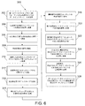
図6は、大気中を伝播する光信号を用いてデータプロセッサ間でデータ通信を行う方法300を示すフローチャートである。一実施形態による方法300は、以下の工程を含む。第1のデータプロセッサから、GBEフォーマットの電気信号の形態のデータビットストリームを送信する(工程302)。第1のデータプロセッサから受信したGBEフォーマットの電気信号をSONETフォーマットの一の波長の光信号に変換する(工程304)。上記一の波長の光信号を別の波長の光信号に変換する(工程306)。上記別の波長の光信号を増幅する(工程308)。増幅した光信号を単モードファイバーを介して第1のテレスコープに送信する(工程310)。工程310で生成した光信号を第1のテレスコープから大気を介して送信する(工程312)。第1のテレスコープによって送信された光信号を第2のテレスコープで受信する(工程314)。第2のテレスコープで受信した光信号を電気信号に変換する(工程316)。工程316で生成された電気信号をSONETフォーマットの再生光信号に変換する(工程318)。再生光信号をデータビットストリームである電気信号に変換する(工程320)。工程320で生成された電気信号に前方誤り訂正を行うことによって、訂正されたデータビットストリームである電気信号を生成する(工程322)。訂正されたデータビットストリームである電気信号を、訂正されたデータビットストリームであるSONETフォーマットの光信号に変換する(工程324)。工程324で生成された光信号を、訂正されたデータビットストリームであるGBEフォーマットの電気信号に変換する(工程326)。訂正されたデータビットストリームであるGBEフォーマットの電気信号を、第2のデータプロセッサで受信する(工程328)。
FIG. 6 is a flowchart illustrating a
このように、上述のシステムは、飛行機と地上局との間のGBEテレメトリデータの自由空間二方向レーザー通信のための二重の大気影響緩和法を採用している。このシステムは、データレートの増大に限界があるとともに電磁干渉の影響を受けやすいRFリンクを用いた手法に対する、実用可能な改善策である。 Thus, the system described above employs a dual atmospheric mitigation method for free-space two-way laser communication of GBE telemetry data between an airplane and a ground station. This system is a practical improvement over approaches using RF links that have limitations in increasing data rates and are susceptible to electromagnetic interference.
種々の実施形態に言及して自由空間レーザー通信システムを説明したが、当業者であればわかるように、本明細書の教示を逸脱することなく、様々な変更が可能であり、システムの要素は、均等の要素で代用することが可能である。また、本明細書に開示した概念及び実施態様を特定の状況に適合させるために、多くの改変を行うことができる。従って、特許請求の範囲によってカバーされる要旨は、開示の実施形態に限定されないことを意図している。 Although the free space laser communication system has been described with reference to various embodiments, it will be appreciated by those skilled in the art that various modifications can be made without departing from the teachings herein, It is possible to substitute an equivalent element. In addition, many modifications may be made to adapt the concepts and embodiments disclosed herein to a particular situation. Accordingly, it is intended that the subject matter covered by the claims not be limited to the disclosed embodiments.
以下に述べる方法クレームは、記載された工程がアルファベット順に行われること(特許請求の範囲におけるあらゆるアルファベット順は、前述した工程に言及する目的のみで使用されている)、又は記載した順に行われることを要件とすると解釈されるべきではない。また、2つ又はそれ以上の工程が同時にあるいは異なる順序で行われることを排除すると解釈されるべきではない。 In the method claims described below, the steps described are performed in alphabetical order (any alphabetical order in the claims is used only for the purpose of referring to the steps described above) or in the order described. Should not be construed as a requirement. Nor should it be construed to exclude that two or more steps are performed simultaneously or in a different order.
以下の項は、本開示のさらなる態様を記載している。 The following sections describe further aspects of the present disclosure.
付記A1.テレスコープと、
前記テレスコープから光信号を受信するように配置された複数のレンズと、
前記レンズによって受信した光信号を電気信号に変換するための複数の光検出器と、
前記光検出器からの前記電気信号を、特定のネットワークプロトコルに従ってフォーマットされた再生光信号に変換するように構成された電子回路と、
前記再生光信号を、データビットストリームである電気信号に変換し、データビットストリームである前記電気信号に前方誤り訂正を行うことによって、訂正されたデータビットストリームである電気信号を生成し、前記訂正されたデータビットストリームである前記電気信号を、前記特定のネットワークプロトコルに従ってフォーマットされた、前記訂正されたデータビットストリームである光信号に変換するように構成された誤り訂正サブシステムと、
前記訂正された光信号を、前記訂正されたデータビットストリームであるGBEフォーマットの電気信号に変換するように構成されたメディアコンバータと、
前記メディアコンバータから受信したGBEフォーマットの電気信号を処理するようにプログラムされたデータプロセッサと、を含むシステム。
Appendix A1. Telescope,
A plurality of lenses arranged to receive optical signals from the telescope;
A plurality of photodetectors for converting optical signals received by the lens into electrical signals;
An electronic circuit configured to convert the electrical signal from the photodetector into a reconstructed optical signal formatted according to a particular network protocol;
The reproduced optical signal is converted into an electrical signal that is a data bit stream, and forward error correction is performed on the electrical signal that is the data bit stream to generate an electrical signal that is a corrected data bit stream, and the correction An error correction subsystem configured to convert the electrical signal, which is a data bitstream, into an optical signal, which is the corrected data bitstream, formatted according to the specific network protocol;
A media converter configured to convert the corrected optical signal to an electrical signal in GBE format that is the corrected data bitstream;
A data processor programmed to process an electrical signal in GBE format received from the media converter.
A2.前記特定のネットワークプロトコルは、シンクロナスオプティカルネットワーキング(Synchronous Optical Networking)である、項A1に記載のシステム。 A2. The system according to Item A1, wherein the specific network protocol is Synchronous Optical Networking.
A3.前記データプロセッサは、少なくとも毎秒1ギガビットの速度でイーサネットフレームを送信するテレメトリプロセッサである、項A1又はA2に記載のシステム。 A3. The system of clause A1 or A2, wherein the data processor is a telemetry processor that transmits Ethernet frames at a rate of at least 1 gigabit per second.
A4.前記データプロセッサは、データビットストリームであるGBEフォーマットの電気信号を前記メディアコンバータに送信するようにさらにプログラムされており、前記メディアコンバータは、前記データプロセッサから受信した前記電気信号を、前記特定のネットワークプロトコルに従ってフォーマットされた、一の波長の光信号に変換するようにさらに構成されており、前記システムは、
前記メディアコンバータから受信した前記一の波長の光信号を別の波長の光信号に変換するように構成された波長コンバータと、
前記別の波長の光信号を増幅するための光増幅器と、
前記増幅された光信号を前記テレスコープに搬送する光接続部と、をさらに備える、項A3に記載のシステム。
A4. The data processor is further programmed to transmit a GBE format electrical signal, which is a data bitstream, to the media converter, the media converter receiving the electrical signal received from the data processor in the specific network. Further configured to convert to an optical signal of one wavelength, formatted according to a protocol, the system comprising:
A wavelength converter configured to convert the optical signal of one wavelength received from the media converter into an optical signal of another wavelength;
An optical amplifier for amplifying the optical signal of another wavelength;
The system of clause A3, further comprising: an optical connection that carries the amplified optical signal to the telescope.
Claims (15)
前記レンズのアレイに光学的に接続されるとともに、前記レンズのアレイに入射する光を差分電気信号に変換するように構成された光通信受信機アレイと、
前記差分電気信号を、特定のネットワークプロトコルに従ってフォーマットされた再生光信号に変換するように構成された再生器と、
前記再生器からの前記再生光信号を、データビットストリームである電気信号に変換し、データビットストリームである前記電気信号に前方誤り訂正を行うことによって、訂正されたデータビットストリームである電気信号を生成し、前記訂正されたデータビットストリームである前記電気信号を、前記特定のネットワークプロトコルに従ってフォーマットされた、前記訂正されたデータビットストリームである光信号に変換するように構成された誤り訂正サブシステムと、
前記誤り訂正サブシステムによって送信された光信号を、前記訂正されたデータビットストリームであるGBEフォーマットの電気信号に変換するように構成されたメディアコンバータと、
前記メディアコンバータから受信したGBEフォーマットの電気信号を処理するようにプログラムされたデータプロセッサと、を含むシステム。 An array of lenses,
An optical communication receiver array optically connected to the array of lenses and configured to convert light incident on the array of lenses into a differential electrical signal;
A regenerator configured to convert the differential electrical signal into a regenerated optical signal formatted according to a particular network protocol;
The reproduced optical signal from the regenerator is converted into an electrical signal that is a data bit stream, and forward error correction is performed on the electrical signal that is the data bit stream, thereby converting the electrical signal that is the corrected data bit stream into An error correction subsystem configured to generate and convert the electrical signal that is the corrected data bitstream into the optical signal that is the corrected data bitstream formatted according to the specific network protocol When,
A media converter configured to convert an optical signal transmitted by the error correction subsystem into an electrical signal in GBE format that is the corrected data bitstream;
A data processor programmed to process an electrical signal in GBE format received from the media converter.
前記メディアコンバータから受信した前記一の波長の光信号を別の波長の光信号に変換するように構成された波長コンバータと、
前記別の波長の光信号を増幅するための光増幅器と、
前記増幅された光信号を前記テレスコープに搬送する光接続部と、をさらに備える、請求項4に記載のシステム。 The data processor is further programmed to transmit a GBE format electrical signal, which is a data bitstream, to the media converter, the media converter receiving the electrical signal received from the data processor in the specific network. Further configured to convert the data bitstream, formatted according to a protocol, into an optical signal of one wavelength, the system comprising:
A wavelength converter configured to convert the optical signal of one wavelength received from the media converter into an optical signal of another wavelength;
An optical amplifier for amplifying the optical signal of another wavelength;
The system of claim 4, further comprising an optical connection that carries the amplified optical signal to the telescope.
データビットストリームであるGBEフォーマットの電気信号を送信するようにプログラムされた第1のデータプロセッサと、
前記第1のデータプロセッサから受信したGBEフォーマットの電気信号を、特定のネットワークプロトコルに従ってフォーマットされた、前記送信されたデータビットストリームである、一の波長の光信号に変換するように構成された第1のメディアコンバータと、
前記第1のメディアコンバータから受信した前記一の波長の光信号を別の波長の光信号に変換するように構成された波長コンバータと、
前記別の波長の光信号を増幅するための光増幅器と、
前記増幅された光信号を前記第1のテレスコープに搬送する光接続部と、
前記第2のテレスコープから光を受信するように配置された第1のレンズのアレイと、
前記第1のレンズのアレイに光学的に接続されるとともに、前記第1のレンズのアレイに入射する光を差分電気信号に変換するように構成された第1の光通信受信機アレイと、
前記差分電気信号を、前記特定のネットワークプロトコルに従ってフォーマットされた再生光信号に変換するように構成された第1の再生器と、
前記第1の再生器からの前記再生光信号を、データビットストリームである電気信号に変換し、データビットストリームである前記電気信号に前方誤り訂正を行うことによって、訂正されたデータビットストリームである電気信号を生成し、前記訂正されたデータビットストリームである前記電気信号を、前記特定のネットワークプロトコルに従ってフォーマットされた、前記訂正されたデータビットストリームである光信号に変換するように構成された第1の誤り訂正サブシステムと、
前記第1の誤り訂正サブシステムからの前記訂正された光信号を、前記訂正されたデータビットストリームであるGBEフォーマットの電気信号に変換するように構成された第2のメディアコンバータと、
前記第2のメディアコンバータから受信したGBEフォーマットの電気信号を処理するようにプログラムされた第2のデータプロセッサと、を含む通信システム。 First and second telescopes;
A first data processor programmed to transmit an electrical signal in a GBE format that is a data bitstream;
A first signal configured to convert an electrical signal in GBE format received from the first data processor into an optical signal of one wavelength, the transmitted data bitstream, formatted according to a specific network protocol; 1 media converter,
A wavelength converter configured to convert the optical signal of one wavelength received from the first media converter into an optical signal of another wavelength;
An optical amplifier for amplifying the optical signal of another wavelength;
An optical connection for carrying the amplified optical signal to the first telescope;
An array of first lenses arranged to receive light from the second telescope;
A first optical communications receiver array optically connected to the first lens array and configured to convert light incident on the first lens array into a differential electrical signal;
A first regenerator configured to convert the differential electrical signal into a reconstructed optical signal formatted according to the specific network protocol;
A data bit stream corrected by converting the reproduced optical signal from the first regenerator into an electric signal that is a data bit stream and performing forward error correction on the electric signal that is a data bit stream. Configured to generate an electrical signal and convert the electrical signal that is the corrected data bitstream into an optical signal that is the corrected data bitstream formatted according to the particular network protocol. One error correction subsystem;
A second media converter configured to convert the corrected optical signal from the first error correction subsystem to an electrical signal in GBE format that is the corrected data bitstream;
A second data processor programmed to process an electrical signal in GBE format received from the second media converter.
前記第2のレンズのアレイに光学的に接続されるとともに、前記第2のレンズのアレイに入射する光を差分電気信号に変換するように構成された第2の光通信受信機アレイと、
前記第2の光通信受信機アレイからの前記差分電気信号を、前記特定のネットワークプロトコルに従ってフォーマットされた再生光信号に変換するように構成された第2の再生器と、
前記第2の再生器からの前記再生光信号を、データビットストリームである電気信号に変換し、データビットストリームである前記電気信号に前方誤り訂正を行うことによって、訂正されたデータビットストリームである電気信号を生成し、前記訂正されたデータビットストリームである前記電気信号を、前記特定のネットワークプロトコルに従ってフォーマットされた、前記訂正されたデータビットストリームである光信号に変換するように構成された、第2の誤り訂正サブシステムと、をさらに含み、
前記第1のメディアコンバータは、前記第2の誤り訂正サブシステムからの前記訂正された光信号を、前記訂正されたデータビットストリームであるGBEフォーマットの電気信号に変換するように構成されている、請求項8〜10のいずれか1つに記載の通信システム。 An array of second lenses arranged to receive light from the first telescope;
A second optical communication receiver array optically connected to the second lens array and configured to convert light incident on the second lens array into a differential electrical signal;
A second regenerator configured to convert the differential electrical signal from the second optical communications receiver array into a reconstructed optical signal formatted according to the specific network protocol;
A data bit stream corrected by converting the reproduced optical signal from the second regenerator into an electric signal that is a data bit stream and performing forward error correction on the electric signal that is a data bit stream. Configured to generate an electrical signal and convert the electrical signal that is the corrected data bitstream into an optical signal that is the corrected data bitstream formatted according to the particular network protocol; A second error correction subsystem;
The first media converter is configured to convert the corrected optical signal from the second error correction subsystem into an electrical signal in GBE format that is the corrected data bitstream. The communication system according to any one of claims 8 to 10.
前記第2のテレスコープと前記第1のレンズのアレイとの間に配置されるとともに、前記第1の波長とは異なる第2の波長を中心とする第2のバンドパスフィルターと、をさらに含む、請求項11に記載の通信システム。 A first bandpass filter disposed between the first telescope and the second lens array and centered at a first wavelength;
A second bandpass filter disposed between the second telescope and the first lens array and centered on a second wavelength different from the first wavelength; The communication system according to claim 11.
(a)第1のデータプロセッサから、GBEフォーマットの電気信号の形態のデータビットストリームを送信することと、
(b)前記第1のデータプロセッサから受信したGBEフォーマットの電気信号を、特定のネットワークプロトコルに従ってフォーマットされた、前記送信されたデータビットストリームである光信号に変換することと、
(c)工程(b)で生成した前記光信号を、第1のテレスコープから大気を介して送信することと、
(d)前記第1のテレスコープによって送信された前記光信号を第2のテレスコープで受信することと、
(e)前記第2のテレスコープで受信した前記光信号を電気信号に変換することと、
(f)工程(e)で生成された前記電気信号を、前記特定のネットワークプロトコルに従ってフォーマットされた再生光信号に変換することと、
(g)前記再生光信号をデータビットストリームである電気信号に変換することと、
(h)工程(g)で生成された電気信号に前方誤り訂正を行うことによって、訂正されたデータビットストリームである電気信号を生成することと、
(i)前記訂正されたデータビットストリームである前記電気信号を、前記特定のネットワークプロトコルに従ってフォーマットされた、前記訂正されたデータビットストリームである光信号に変換することと、
(j)工程(i)で生成された光信号を、前記訂正されたデータビットストリームであるGBEフォーマットの電気信号に変換することと、
(k)前記訂正されたデータビットストリームであるGBEフォーマットの電気信号を、第2のデータプロセッサで受信することと、を含む方法。 A method of performing data communication between data processors using an optical signal propagating in the atmosphere,
(A) transmitting a data bit stream in the form of an electrical signal in the GBE format from the first data processor;
(B) converting an electrical signal in GBE format received from the first data processor into an optical signal that is the transmitted data bitstream formatted according to a specific network protocol;
(C) transmitting the optical signal generated in step (b) from the first telescope via the atmosphere;
(D) receiving the optical signal transmitted by the first telescope at a second telescope;
(E) converting the optical signal received by the second telescope into an electrical signal;
(F) converting the electrical signal generated in step (e) into a reproduced optical signal formatted according to the specific network protocol;
(G) converting the reproduced optical signal into an electrical signal which is a data bit stream;
(H) generating an electrical signal that is a corrected data bitstream by performing forward error correction on the electrical signal generated in step (g);
(I) converting the electrical signal that is the corrected data bitstream into an optical signal that is the corrected data bitstream formatted according to the specific network protocol;
(J) converting the optical signal generated in step (i) into an electrical signal in GBE format that is the corrected data bit stream;
(K) receiving a GBE format electrical signal that is the corrected data bitstream at a second data processor.
前記第1のデータプロセッサから受信したGBEフォーマットの電気信号を、前記特定のネットワークプロトコルに従ってフォーマットされた、一の波長の光信号に変換することと、
前記一の波長の光信号を別の波長の光信号に変換することと、
前記別の波長の光信号を増幅することと、
前記増幅した光信号を単モードファイバーを介して前記第1のテレスコープに送信することと、を含む請求項13に記載の方法。 The step (b)
Converting an electrical signal in GBE format received from the first data processor into an optical signal of one wavelength formatted according to the specific network protocol;
Converting the optical signal of one wavelength into an optical signal of another wavelength;
Amplifying the optical signal of another wavelength;
14. The method of claim 13, comprising transmitting the amplified optical signal to the first telescope via a single mode fiber.
Applications Claiming Priority (2)
| Application Number | Priority Date | Filing Date | Title |
|---|---|---|---|
| US14/684,748 | 2015-04-13 | ||
| US14/684,748 US9438338B1 (en) | 2015-04-13 | 2015-04-13 | System for bidirectional free-space laser communication of gigabit Ethernet telemetry data |
Related Child Applications (1)
| Application Number | Title | Priority Date | Filing Date |
|---|---|---|---|
| JP2019009861A Division JP6757428B2 (en) | 2015-04-13 | 2019-01-24 | Two-way free space laser communication system for Gigabit Ethernet telemetry data |
Publications (2)
| Publication Number | Publication Date |
|---|---|
| JP2016201790A true JP2016201790A (en) | 2016-12-01 |
| JP2016201790A5 JP2016201790A5 (en) | 2018-05-24 |
Family
ID=55752187
Family Applications (2)
| Application Number | Title | Priority Date | Filing Date |
|---|---|---|---|
| JP2016068361A Pending JP2016201790A (en) | 2015-04-13 | 2016-03-30 | Two-way free space laser communication system for gigabit ethernet telemetry data |
| JP2019009861A Active JP6757428B2 (en) | 2015-04-13 | 2019-01-24 | Two-way free space laser communication system for Gigabit Ethernet telemetry data |
Family Applications After (1)
| Application Number | Title | Priority Date | Filing Date |
|---|---|---|---|
| JP2019009861A Active JP6757428B2 (en) | 2015-04-13 | 2019-01-24 | Two-way free space laser communication system for Gigabit Ethernet telemetry data |
Country Status (4)
| Country | Link |
|---|---|
| US (1) | US9438338B1 (en) |
| EP (1) | EP3082277B1 (en) |
| JP (2) | JP2016201790A (en) |
| CN (1) | CN106059678B (en) |
Cited By (2)
| Publication number | Priority date | Publication date | Assignee | Title |
|---|---|---|---|---|
| JPWO2021090481A1 (en) * | 2019-11-08 | 2021-05-14 | ||
| WO2022004106A1 (en) * | 2020-07-01 | 2022-01-06 | 日本電気株式会社 | Light receiving device and communication device |
Families Citing this family (13)
| Publication number | Priority date | Publication date | Assignee | Title |
|---|---|---|---|---|
| CN106357317A (en) * | 2016-12-06 | 2017-01-25 | 南通大学 | Method for restraining atmosphere turbulence interference in free-space optical communication |
| US10484095B2 (en) | 2017-06-15 | 2019-11-19 | The Aerospace Corporation | Communications relay satellite with a single-axis gimbal |
| CN107741280B (en) * | 2017-11-22 | 2019-05-17 | 长春理工大学 | Light beam forward direction turbulence transfer drift angle and reverse transfer angle of arrival related coefficient measurement method |
| US10574359B2 (en) | 2018-03-20 | 2020-02-25 | The Boeing Company | Single-wavelength bidirectional transceiver with integrated optical fiber coupler |
| US10707966B2 (en) * | 2018-05-14 | 2020-07-07 | California Institute Of Technology | Ultrafast omnidirectional wireless data transfer apparatus and system |
| CN109120908B (en) * | 2018-09-19 | 2023-12-05 | 长春晟德科技有限公司 | Remote free space light transmission method and system for forest fire prevention monitoring |
| US10754111B1 (en) * | 2019-04-22 | 2020-08-25 | The Boeing Company | Method for modifying small form factor pluggable transceiver for avionics applications |
| US10944584B1 (en) * | 2019-10-11 | 2021-03-09 | Credo Technology Group Limited | Single-ended signaling between differential ethernet interfaces |
| CN110827443B (en) * | 2019-10-24 | 2021-07-06 | 张东 | Remote measurement post data processing system |
| CN113346925B (en) | 2020-03-01 | 2022-11-18 | 默升科技集团有限公司 | Active Ethernet cable and manufacturing method thereof |
| US11491651B2 (en) | 2020-03-03 | 2022-11-08 | The Boeing Company | Data communication network with gigabit plastic optical fiber for robotic arm system |
| US11616574B2 (en) | 2020-03-26 | 2023-03-28 | California Institute Of Technology | Optical ground terminal |
| US11567264B2 (en) * | 2021-04-28 | 2023-01-31 | Com Dev Ltd. | Wavelength separated fine steering assembly |
Citations (5)
| Publication number | Priority date | Publication date | Assignee | Title |
|---|---|---|---|---|
| JPH1155187A (en) * | 1997-08-07 | 1999-02-26 | Nec Corp | Optical spatial transmitter |
| JP2004080064A (en) * | 2002-06-21 | 2004-03-11 | Fujikura Ltd | Wavelength demultiplexing and multiplexing device and wavelength multiplex communication system |
| US6829741B1 (en) * | 2001-07-27 | 2004-12-07 | Centillium Communications, Inc. | Forward error correction (FEC) based on SONET/SDH framing |
| US20060076473A1 (en) * | 2004-10-08 | 2006-04-13 | Wilcken Stephen K | Lenslet/detector array assembly for high data rate optical communications |
| US20130315604A1 (en) * | 2011-02-07 | 2013-11-28 | The Board Of Regents Of The University Of Oklahoma | Mobile bi-directional free-space optical network |
Family Cites Families (17)
| Publication number | Priority date | Publication date | Assignee | Title |
|---|---|---|---|---|
| US6285481B1 (en) | 1997-09-05 | 2001-09-04 | Trex Communications Corporation | Free-space laser communications error control system |
| IL140896A0 (en) * | 1998-07-16 | 2002-02-10 | Terabeam Networks Inc | Optical communication system that transmits and receives data through free space |
| US7136585B2 (en) | 2001-12-14 | 2006-11-14 | Kiribati Wireless Ventures, Llc | Optical amplifiers in a free space laser communication system |
| US7197248B1 (en) | 2002-07-29 | 2007-03-27 | United States Of America As Represented By The Secretary Of The Army | Adaptive correction of wave-front phase distortions in a free-space laser communication system and method |
| US8041224B2 (en) * | 2007-06-14 | 2011-10-18 | Celight, Inc. | Optical frequency division multiplexed communications over the horizon |
| JP4113824B2 (en) * | 2003-09-24 | 2008-07-09 | シリンクス株式会社 | Receiver circuit for optical space communication |
| US7343099B2 (en) | 2004-02-12 | 2008-03-11 | Metrologic Instruments, Inc. | Free space optical (FSO) laser communication system employing fade mitigation measures based on laser beam speckle tracking and locking principles |
| US7457545B2 (en) * | 2004-02-12 | 2008-11-25 | Northrop Grumman Corporation | Process for controlling a Hartmann wavefront sensor (WFS) in an adaptive optic (AO) system |
| JP5031427B2 (en) * | 2007-03-30 | 2012-09-19 | 三星電子株式会社 | Visible light transmitter, visible light receiver, visible light communication system, and visible light communication method |
| US8301032B2 (en) * | 2008-02-12 | 2012-10-30 | Arun Kumar Majumdar | Wide field-of-view amplified fiber-retro for secure high data rate communications and remote data transfer |
| US8355635B1 (en) | 2009-09-01 | 2013-01-15 | The Boeing Company | Gyro-aided pointing control for laser communications |
| CN101771468B (en) * | 2009-12-24 | 2012-12-19 | 中国科学院安徽光学精密机械研究所 | Correction system of laser atmospheric transmission inclination |
| US8478127B2 (en) | 2010-07-29 | 2013-07-02 | The Boeing Company | Burst mode optical media converter with fast analog conversion |
| CN101968567B (en) * | 2010-09-30 | 2012-06-06 | 华中科技大学 | Novel self-adaptive optical method and system of wavefront-free sensor |
| US8942562B2 (en) * | 2011-05-31 | 2015-01-27 | A Optix Technologies, Inc. | Integrated commercial communications network using radio frequency and free space optical data communication |
| US20120308239A1 (en) * | 2011-06-03 | 2012-12-06 | Sheth Samir S | Active Tracking for Free-Space Optical Communication Systems |
| TWI485504B (en) * | 2012-08-28 | 2015-05-21 | Ind Tech Res Inst | Light communication system, transmitter apparatus and receiver apparatus |
-
2015
- 2015-04-13 US US14/684,748 patent/US9438338B1/en active Active
-
2016
- 2016-03-30 JP JP2016068361A patent/JP2016201790A/en active Pending
- 2016-04-11 EP EP16164734.2A patent/EP3082277B1/en active Active
- 2016-04-12 CN CN201610225712.2A patent/CN106059678B/en active Active
-
2019
- 2019-01-24 JP JP2019009861A patent/JP6757428B2/en active Active
Patent Citations (5)
| Publication number | Priority date | Publication date | Assignee | Title |
|---|---|---|---|---|
| JPH1155187A (en) * | 1997-08-07 | 1999-02-26 | Nec Corp | Optical spatial transmitter |
| US6829741B1 (en) * | 2001-07-27 | 2004-12-07 | Centillium Communications, Inc. | Forward error correction (FEC) based on SONET/SDH framing |
| JP2004080064A (en) * | 2002-06-21 | 2004-03-11 | Fujikura Ltd | Wavelength demultiplexing and multiplexing device and wavelength multiplex communication system |
| US20060076473A1 (en) * | 2004-10-08 | 2006-04-13 | Wilcken Stephen K | Lenslet/detector array assembly for high data rate optical communications |
| US20130315604A1 (en) * | 2011-02-07 | 2013-11-28 | The Board Of Regents Of The University Of Oklahoma | Mobile bi-directional free-space optical network |
Non-Patent Citations (2)
| Title |
|---|
| "Network node interface for the synchronous digital hierarchy (SDH)", ITU-T RECOMMENDATION G.707/Y.1322, JPN6018017581, January 2007 (2007-01-01), pages 第77頁 * |
| STAMATIOS V. KARTALOPOULOS: "Seamless integration of wireless access, free space optical, and fiber-based backbone networks", 2012 IEEE NETWORK OPERATIONS AND MANAGEMENT SYMPOSIUM (NOMS), JPN6018017579, 2012, US, pages 第1399-1402頁 * |
Cited By (5)
| Publication number | Priority date | Publication date | Assignee | Title |
|---|---|---|---|---|
| JPWO2021090481A1 (en) * | 2019-11-08 | 2021-05-14 | ||
| WO2021090481A1 (en) * | 2019-11-08 | 2021-05-14 | 株式会社島津製作所 | Optical communication device |
| JP7383268B2 (en) | 2019-11-08 | 2023-11-20 | 株式会社島津製作所 | optical communication equipment |
| US11929786B2 (en) | 2019-11-08 | 2024-03-12 | Shimadzu Corporation | Optical communication device |
| WO2022004106A1 (en) * | 2020-07-01 | 2022-01-06 | 日本電気株式会社 | Light receiving device and communication device |
Also Published As
| Publication number | Publication date |
|---|---|
| EP3082277A1 (en) | 2016-10-19 |
| JP2019110540A (en) | 2019-07-04 |
| EP3082277B1 (en) | 2018-10-03 |
| CN106059678A (en) | 2016-10-26 |
| US9438338B1 (en) | 2016-09-06 |
| JP6757428B2 (en) | 2020-09-16 |
| CN106059678B (en) | 2019-04-09 |
Similar Documents
| Publication | Publication Date | Title |
|---|---|---|
| JP6757428B2 (en) | Two-way free space laser communication system for Gigabit Ethernet telemetry data | |
| US10177842B2 (en) | Enhanced transmission and reception of remote digital diagnostic information of optical tranceivers | |
| CA2889966C (en) | Integrated circuits in optical receivers | |
| US7380993B2 (en) | Optical transceiver for 100 gigabit/second transmission | |
| CN102104431B (en) | Dual-rate receiving device in optical transceiver | |
| CN107517080B (en) | Optical power detection method, device, equipment and optical module | |
| US20060198639A1 (en) | High speed SFP transceiver | |
| JP2016201790A5 (en) | ||
| US11342994B2 (en) | N-input receiver: RFoG OBI mitigation with retransmission | |
| CN105634611A (en) | Optical module and signal processing method | |
| CN112671502A (en) | Optical line terminal | |
| CN114647030A (en) | Silicon-based photoelectronic receiving and transmitting integrated chip for PON OLT system | |
| EP3270529B1 (en) | Optical transmission assembly | |
| Chand et al. | Optical LAN for avionics platforms |
Legal Events
| Date | Code | Title | Description |
|---|---|---|---|
| A521 | Request for written amendment filed |
Free format text: JAPANESE INTERMEDIATE CODE: A523 Effective date: 20180406 |
|
| A621 | Written request for application examination |
Free format text: JAPANESE INTERMEDIATE CODE: A621 Effective date: 20180406 |
|
| A871 | Explanation of circumstances concerning accelerated examination |
Free format text: JAPANESE INTERMEDIATE CODE: A871 Effective date: 20180406 |
|
| A975 | Report on accelerated examination |
Free format text: JAPANESE INTERMEDIATE CODE: A971005 Effective date: 20180419 |
|
| A131 | Notification of reasons for refusal |
Free format text: JAPANESE INTERMEDIATE CODE: A131 Effective date: 20180522 |
|
| A02 | Decision of refusal |
Free format text: JAPANESE INTERMEDIATE CODE: A02 Effective date: 20180925 |