JP2016201077A - Information processing unit, control method thereof, and program - Google Patents
Information processing unit, control method thereof, and program Download PDFInfo
- Publication number
- JP2016201077A JP2016201077A JP2015082857A JP2015082857A JP2016201077A JP 2016201077 A JP2016201077 A JP 2016201077A JP 2015082857 A JP2015082857 A JP 2015082857A JP 2015082857 A JP2015082857 A JP 2015082857A JP 2016201077 A JP2016201077 A JP 2016201077A
- Authority
- JP
- Japan
- Prior art keywords
- sleep mode
- information processing
- processing apparatus
- packet
- sleep
- Prior art date
- Legal status (The legal status is an assumption and is not a legal conclusion. Google has not performed a legal analysis and makes no representation as to the accuracy of the status listed.)
- Pending
Links
- 238000000034 method Methods 0.000 title claims abstract description 67
- 230000010365 information processing Effects 0.000 title claims abstract description 36
- 230000007704 transition Effects 0.000 claims description 23
- 230000008859 change Effects 0.000 claims description 8
- 230000004043 responsiveness Effects 0.000 abstract 2
- 230000008569 process Effects 0.000 description 51
- 230000004044 response Effects 0.000 description 33
- 238000012545 processing Methods 0.000 description 30
- WBMKMLWMIQUJDP-STHHAXOLSA-N (4R,4aS,7aR,12bS)-4a,9-dihydroxy-3-prop-2-ynyl-2,4,5,6,7a,13-hexahydro-1H-4,12-methanobenzofuro[3,2-e]isoquinolin-7-one hydrochloride Chemical compound Cl.Oc1ccc2C[C@H]3N(CC#C)CC[C@@]45[C@@H](Oc1c24)C(=O)CC[C@@]35O WBMKMLWMIQUJDP-STHHAXOLSA-N 0.000 description 20
- 238000010586 diagram Methods 0.000 description 16
- 230000005540 biological transmission Effects 0.000 description 9
- 238000001514 detection method Methods 0.000 description 6
- 230000006870 function Effects 0.000 description 5
- 238000001444 catalytic combustion detection Methods 0.000 description 3
- 238000004891 communication Methods 0.000 description 2
- 238000005259 measurement Methods 0.000 description 2
- 238000003825 pressing Methods 0.000 description 2
- 238000012546 transfer Methods 0.000 description 2
- 238000004458 analytical method Methods 0.000 description 1
- 239000003086 colorant Substances 0.000 description 1
- 230000003111 delayed effect Effects 0.000 description 1
- 230000000694 effects Effects 0.000 description 1
- 239000011521 glass Substances 0.000 description 1
- 238000007562 laser obscuration time method Methods 0.000 description 1
- 239000000463 material Substances 0.000 description 1
- 238000012986 modification Methods 0.000 description 1
- 230000004048 modification Effects 0.000 description 1
- 230000035945 sensitivity Effects 0.000 description 1
- 238000005092 sublimation method Methods 0.000 description 1
Images


Classifications
-
- G—PHYSICS
- G06—COMPUTING; CALCULATING OR COUNTING
- G06F—ELECTRIC DIGITAL DATA PROCESSING
- G06F1/00—Details not covered by groups G06F3/00 - G06F13/00 and G06F21/00
- G06F1/26—Power supply means, e.g. regulation thereof
- G06F1/32—Means for saving power
- G06F1/3203—Power management, i.e. event-based initiation of a power-saving mode
- G06F1/3234—Power saving characterised by the action undertaken
- G06F1/3287—Power saving characterised by the action undertaken by switching off individual functional units in the computer system
-
- G—PHYSICS
- G06—COMPUTING; CALCULATING OR COUNTING
- G06F—ELECTRIC DIGITAL DATA PROCESSING
- G06F1/00—Details not covered by groups G06F3/00 - G06F13/00 and G06F21/00
- G06F1/26—Power supply means, e.g. regulation thereof
- G06F1/32—Means for saving power
- G06F1/3203—Power management, i.e. event-based initiation of a power-saving mode
- G06F1/3206—Monitoring of events, devices or parameters that trigger a change in power modality
- G06F1/3209—Monitoring remote activity, e.g. over telephone lines or network connections
-
- G—PHYSICS
- G06—COMPUTING; CALCULATING OR COUNTING
- G06F—ELECTRIC DIGITAL DATA PROCESSING
- G06F1/00—Details not covered by groups G06F3/00 - G06F13/00 and G06F21/00
- G06F1/26—Power supply means, e.g. regulation thereof
- G06F1/32—Means for saving power
- G06F1/3203—Power management, i.e. event-based initiation of a power-saving mode
- G06F1/3234—Power saving characterised by the action undertaken
- G06F1/325—Power saving in peripheral device
- G06F1/3284—Power saving in printer
-
- H—ELECTRICITY
- H04—ELECTRIC COMMUNICATION TECHNIQUE
- H04N—PICTORIAL COMMUNICATION, e.g. TELEVISION
- H04N1/00—Scanning, transmission or reproduction of documents or the like, e.g. facsimile transmission; Details thereof
- H04N1/00885—Power supply means, e.g. arrangements for the control of power supply to the apparatus or components thereof
-
- Y—GENERAL TAGGING OF NEW TECHNOLOGICAL DEVELOPMENTS; GENERAL TAGGING OF CROSS-SECTIONAL TECHNOLOGIES SPANNING OVER SEVERAL SECTIONS OF THE IPC; TECHNICAL SUBJECTS COVERED BY FORMER USPC CROSS-REFERENCE ART COLLECTIONS [XRACs] AND DIGESTS
- Y02—TECHNOLOGIES OR APPLICATIONS FOR MITIGATION OR ADAPTATION AGAINST CLIMATE CHANGE
- Y02D—CLIMATE CHANGE MITIGATION TECHNOLOGIES IN INFORMATION AND COMMUNICATION TECHNOLOGIES [ICT], I.E. INFORMATION AND COMMUNICATION TECHNOLOGIES AIMING AT THE REDUCTION OF THEIR OWN ENERGY USE
- Y02D10/00—Energy efficient computing, e.g. low power processors, power management or thermal management
Abstract
Description
本発明は、情報処理装置とその制御方法、及びプログラムに関する。 The present invention relates to an information processing apparatus, a control method thereof, and a program.
画像形成装置が接続されるネットワーク環境は、接続されているPCの台数や各会社によって構築されているネットワークのインフラによって大きく異なる。ネットワーク環境は各ユーザや会社において異なるが、装置が省電力状態に移行する際の条件としては、装置内部で持っているタイマ(省電力状態への移行時間の計時)による省電力状態への移行指示に依っている。また或いは、ユーザからの指示(例えばスイッチ押下)によっても省電力状態に遷移するようになっている。 The network environment to which the image forming apparatus is connected varies greatly depending on the number of connected PCs and the network infrastructure constructed by each company. Although the network environment differs for each user or company, the conditions for the device to transition to the power saving state are the transition to the power saving state using the timer (time measurement of the transition time to the power saving state) that the device has. Depends on instructions. Alternatively, a transition to the power saving state is also made by an instruction from the user (for example, pressing a switch).
例えば特許文献1には、ネットワーク端末装置において、単位時間あたりに受信したパケットの数でネットワークの混雑度を検出して省電力モードを設定することが記載されている。 For example, Patent Document 1 describes that in a network terminal device, the network power level is set by detecting the degree of network congestion based on the number of packets received per unit time.
画像形成装置が接続されるネットワーク環境は様々であり、例えばネットワークトラフィックが多い環境においてCPUが省電力状態になってしまうと、受信パケットに対する応答が通常状態よりも劣るためユーザの利便性を低下させる可能性がある。それに対してCPUを動作状態にして、受信パケットへの応答性を上げると消費電力が増えてしまうことが考えられる。 There are various network environments to which the image forming apparatus is connected. For example, if the CPU is in a power saving state in an environment where there is a lot of network traffic, the response to the received packet is inferior to the normal state, thus reducing the convenience for the user. there is a possibility. On the other hand, it is conceivable that the power consumption increases when the CPU is set in the operating state to increase the response to the received packet.
また上記従来技術のように、単位時間当たりに受信したパケットの数で省電力モードを設定すると、より消費電力の少ない省電力モードでも受信パケットに応答できるにも拘らず、そのような省電力モードに移行させることができなくなる。 In addition, when the power saving mode is set by the number of packets received per unit time as in the above prior art, such a power saving mode can be used even though the power saving mode with less power consumption can respond to the received packet. Cannot be transferred to.
本発明の目的は、上記従来技術の課題を解決することにある。 An object of the present invention is to solve the above-described problems of the prior art.
本発明の特徴は、ネットワークトラフィックに応じたスリープモードに移行するともに、消費電力を抑えることができる技術を提供することにある。 A feature of the present invention is to provide a technique capable of shifting to a sleep mode according to network traffic and suppressing power consumption.
上記目的を達成するために本発明の一態様に係る情報処理装置は以下のような構成を備える。即ち、
複数のスリープモードを有する情報処理装置であって、
スリープモードに移行する条件を満足したかどうかを判定する判定手段と、
特定のパケットの受信時間間隔を計時する計時手段と、
前記計時手段により計時した前記受信時間間隔に基づいて、前記複数のスリープモードのいずれに移行するかを決定する決定手段と、
前記判定手段が前記条件を満足したと判定すると、前記決定手段により決定されたスリープモードに移行するように制御する制御手段と、を有することを特徴とする。
In order to achieve the above object, an information processing apparatus according to an aspect of the present invention has the following arrangement. That is,
An information processing apparatus having a plurality of sleep modes,
A determination means for determining whether or not a condition for shifting to the sleep mode is satisfied;
A time measuring means for measuring a reception time interval of a specific packet;
Determining means for determining which of the plurality of sleep modes to transition to based on the reception time interval timed by the time measuring means;
Control means for controlling to shift to the sleep mode determined by the determining means when the determining means determines that the condition is satisfied.
また本発明の一態様に係る情報処理装置は以下のような構成を備える。即ち、
複数のスリープモードを有する情報処理装置であって、
前記複数のスリープモードのうち、いずれのスリープモードを前記情報処理装置に適用するかをユーザの指示に従って選択する選択手段と、
スリープモードに移行する条件を満足したかどうかを判定する第1の判定手段と、
前記第1の判定手段が前記条件を満足したと判定すると、前記選択手段によって選択されているスリープモードに移行するように制御する制御手段と、
特定のパケットの受信時間間隔を計時する計時手段と、
前記情報処理装置に適用するスリープモードを、前記選択手段によって選択されているスリープモードから他のスリープモードに変更するようにユーザに促すか否かを、前記計時手段により計時した前記受信時間間隔に基づいて判定する第2の判定手段と、
ユーザに促すと前記第2の判定手段によって判定された場合に、前記情報処理装置に適用するスリープモードを変更するようにユーザに促す通知手段と、を有することを特徴とする。
An information processing apparatus according to one embodiment of the present invention includes the following configuration. That is,
An information processing apparatus having a plurality of sleep modes,
Selecting means for selecting which sleep mode of the plurality of sleep modes to apply to the information processing apparatus according to a user instruction;
First determination means for determining whether or not a condition for shifting to the sleep mode is satisfied;
Control means for controlling to shift to the sleep mode selected by the selection means when the first determination means determines that the condition is satisfied;
A time measuring means for measuring a reception time interval of a specific packet;
Whether or not to prompt the user to change the sleep mode applied to the information processing apparatus from the sleep mode selected by the selection unit to another sleep mode is set in the reception time interval measured by the timing unit. Second determination means for determining based on;
And a notification unit that prompts the user to change a sleep mode applied to the information processing apparatus when the second determination unit determines that the user is prompted.
本発明によれば、特定のパケットの受信時間間隔に基づいてスリープモードを設定することにより、ユーザへの利便性を維持しながら低消費電力状態に移行させることが可能となる。 According to the present invention, by setting the sleep mode based on the reception time interval of a specific packet, it is possible to shift to a low power consumption state while maintaining convenience for the user.
本発明のその他の特徴及び利点は、添付図面を参照とした以下の説明により明らかになるであろう。なお、添付図面においては、同じ若しくは同様の構成には、同じ参照番号を付す。 Other features and advantages of the present invention will become apparent from the following description with reference to the accompanying drawings. In the accompanying drawings, the same or similar components are denoted by the same reference numerals.
添付図面は明細書に含まれ、その一部を構成し、本発明の実施形態を示し、その記述と共に本発明の原理を説明するために用いられる。
以下、添付図面を参照して本発明の実施形態を詳しく説明する。尚、以下の実施形態は特許請求の範囲に係る本発明を限定するものでなく、また本実施形態で説明されている特徴の組み合わせの全てが本発明の解決手段に必須のものとは限らない。尚、本発明の情報処理装置の一例として画像形成装置を例に説明するが、本発明はこれに限定されるものでなく、例えば通信装置やファクシミリ装置、複合機等にも適用できる。 Hereinafter, embodiments of the present invention will be described in detail with reference to the accompanying drawings. The following embodiments do not limit the present invention according to the claims, and all combinations of features described in the embodiments are not necessarily essential to the solution means of the present invention. . An image forming apparatus will be described as an example of the information processing apparatus of the present invention. However, the present invention is not limited to this, and can be applied to, for example, a communication apparatus, a facsimile machine, and a multifunction machine.
[実施形態1]
図1は、本発明の実施形態1に係る画像形成装置を含むネットワークシステムの構成例を示す図である。
[Embodiment 1]
FIG. 1 is a diagram illustrating a configuration example of a network system including an image forming apparatus according to Embodiment 1 of the present invention.
図1に示す例では、外部装置であるホストコンピュータ40,50、及び画像形成装置10,20,30がLAN60に接続されているが、本発明はこれらの構成に限られるものではない。また、実施形態1では、これら装置はLANを介して接続されているが、本発明はこれに限定されるものでなく、例えばWAN(公衆回線)や無線回線などの任意のネットワークであっても良い。
In the example shown in FIG. 1,
ホストコンピュータ(以下、PC)40,50は、一般的なパーソナルコンピュータの機能を有している。これらPC40,50は、LAN60やWANを介してFTPやSMBプロトコルを用いファイルや電子メールを送受信することができる。また、PC40,50は、画像形成装置10,20,30に対して、プリンタドライバを介した印刷命令を発行できる。更に、PC40,50は、例えばSNMPパケットを用いて定期的に画像形成装置10,20,30に対して画像形成装置の状態を問い合わせることができる。画像形成装置10,20,30は、PC40,50からの要求に応答して、印刷可能か否かなどの情報を返信できる。また画像形成装置10と画像形成装置20は同じ構成を有する。画像形成装置10,20はスキャナ部を有しているのに対して、画像形成装置30はプリンタ部を有してプリント機能を有するが、スキャナ部を有していない点が相違している。
Host computers (hereinafter referred to as PCs) 40 and 50 have the functions of a general personal computer. These
以下では説明を簡単にするために、画像形成装置10,20のうちの画像形成装置10に注目して、その構成と動作を詳細に説明するが、画像形成装置20についても同様である。また画像形成装置30は、スキャナ部を有していないが、他の構成及び動作は基本的に画像形成装置10と同様である。
In the following, for the sake of simplicity, the configuration and operation of the
画像形成装置10は、画像入力デバイスであるスキャナ部13、画像出力デバイスであるプリンタ部14、画像形成装置10全体の動作制御を司る制御部11、ユーザインターフェース(UI)である操作部12を有する。
The
次に画像形成装置10の構成を説明する。
Next, the configuration of the
図2は、実施形態1に係る画像形成装置10の外観の一例を示す図である。
FIG. 2 is a diagram illustrating an example of the appearance of the
スキャナ部13は、複数のCCDを有している。これら複数のCCDのそれぞれの感度が互いに異なっていると、例え原稿上の各画素の濃度が同じであったとしても、各画素がそれぞれ互いに異なる濃度であると認識されてしまう。そのためスキャナ部13では、最初に白板(一様に白い板)を露光走査し、露光走査して得られた反射光の量を電気信号に変換して制御部11に出力している。
The
次に、原稿上の画像をスキャンする構成について説明する。 Next, a configuration for scanning an image on a document will be described.
スキャナ部13は、原稿上の画像を露光走査して得られた反射光をCCDに入力することで、原稿画像の情報を電気信号に変換する。更に、スキャナ部13は、電気信号をR,G,B各色からなる輝度信号に変換し、その輝度信号を画像データとして制御部11に対して出力する。尚、原稿は、原稿フィーダ201のトレイ202にセットされる。ユーザが操作部12から読み取り開始を指示すると、制御部11からスキャナ部13に原稿の読み取り指示が与えられる。スキャナ部13は、この指示を受けると原稿フィーダ201のトレイ202から原稿を1枚ずつフィードして原稿の読み取りを行う。尚、原稿の読み取り方法は、原稿フィーダ201による自動送り方式ではなく、原稿を不図示のガラス面上に載置し露光部を移動させることで原稿の走査を行う方法であってもよい。
The
プリンタ部14は、制御部11から受取った画像データを用紙上に形成する画像形成デバイスである。尚、実施形態1における画像形成方式は、感光体ドラムや感光体ベルトを用いた電子写真方式となっているが、本発明はこれに限定されない。例えば、微少ノズルアレイからインクを吐出して用紙上に画像を印刷するインクジェット方式や昇華式等の他の印刷方法でも本発明は適用可能である。また、プリンタ部14には、異なる用紙サイズ又は異なる用紙向きを選択可能とする複数の用紙カセット203,204,205が設けられている。排紙トレイ206には、印刷済の用紙が排出される。
The
図3は、実施形態1に係る画像形成装置10の制御部11の構成を説明するブロック図である。
FIG. 3 is a block diagram illustrating the configuration of the
制御部11は、スキャナ部13やプリンタ部14と電気的に接続されており、一方ではLAN60などを介してPC40,50や外部の装置などと接続されている。これにより制御部11には、画像データやデバイス情報の入出力が可能となっている。
The
CPU301は、ROM303に記憶された制御プログラム等に基づいて接続中の各種デバイスとのアクセスを統括的に制御すると共に、制御部11内部で行われる各種処理についても統括的に制御する。またLAN60経由で受信したネットワークパケットに対する処理も行う。RAM302は、CPU301が動作するときのワークメモリとして使用され、かつ画像データを一時記憶するためのメモリとしても利用される。このRAM302は、SRAM及びDRAMにより構成されている。ROM303は、この画像形成装置10のブートプログラムなどが格納されている。HDD304はハードディスクドライブであり、システムソフトウェアや画像データを格納することが可能となっている。操作部I/F305は、システムバス307と操作部12とを接続するためのインターフェース部である。この操作部I/F305は、操作部12に表示するための画像データをシステムバス307から受取って操作部12に出力する。また操作部I/F305は、操作部12から入力された情報をシステムバス307へ出力する。LANコントローラ306は、LAN60とシステムバス307とに接続し、情報の入出力を行うことにより、画像形成装置10とLAN60との通信を制御する。タイマ314はRTC(Real Time Clock)で、CPU301の指示により計時を行って、その計時した時間をCPU301に通知する。
The
画像バス308は、画像データをやり取りするための伝送路であり、PCIバス又はIEEE1394で構成されている。画像処理部309は、画像処理を行うためのものであり、RAM302に記憶された画像データを読み出し、JPEG,JBIGなどの符号化、復号化、及び、色調整などの画像処理を行うことが可能である。スキャナ画像処理部310は、スキャナ部13からスキャナI/F311を介して受取った画像データに対して、補正、加工及び編集等を行う。尚、スキャナ画像処理部310は、受取った画像データに基づいて、読み取った原稿がカラー原稿か白黒データか、文字原稿か写真原稿かなどの判定を行う。そしてスキャナ画像処理部310は、その判定結果を画像データに付随して出力する。こうした付随情報を属性データと称する。
The
プリンタ画像処理部312は、画像データに付随している属性データを参照して、その画像データに画像処理を施す。画像処理後の画像データは、プリンタI/F313を介してプリンタ部14に出力される。
The printer
電源制御部320は、起動時や電源オフ時の電源制御や省電力状態への移行、及び省電力状態からの復帰といった電源状態の変更を制御する。また電源制御部320は、省電力状態から復帰する場合の復帰要因(例えばFAX受信やスイッチ押下等)を検知する部分であり、電源制御部320は各復帰要因に応じて、スタンバイ状態へ移行した際の電源制御を実施する。また電源制御部320は、CPU301からの命令や後述のWake信号等の省電力状態からの復帰検出用の信号等を受け、それによって第一電源供給部409(図4)や第二電源供給部410(図4)から各部に対して電源供給を行うかどうかの制御を行う。
The power
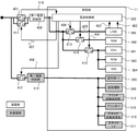
図4は、実施形態1に係る画像形成装置10の制御部11による電源制御を説明するブロック図である。
FIG. 4 is a block diagram illustrating power control by the
電源制御部320は、CPU301からの命令や、LANコントローラ306からのスリープ状態からの復帰検出用の信号等(Wake1信号402、Wake2信号403等)を受信する。そして、それら命令や信号に応じて、第一電源供給部409や第二電源供給部410から各部に対して電源供給を行うかどうかの制御を行う。
The power
第一電源供給部409は、画像形成装置10がスリープ状態においても電源を供給し、例えば、5Vの電力(第1電力)を供給する。第二電源供給部410は、画像形成装置10がスリープ状態のときに電源供給をオフにするもので、例えば、12Vの電力(第2電力)を供給する。即ち、第二電源供給部410が供給する第2電力は、第一電源供給部409が供給する第1電力より高い電圧の電力である。
The first
電源制御部320は、制御信号404〜408の制御を行い、ジョブの実行が可能なスタンバイ状態では図3の参照番号305及び309〜313で示す部分に第2電力を供給する。更に、参照番号301〜304、LANコントローラ306及び電源制御部320に第1電力を供給するように電源を制御する。また電源制御部320は、制御信号404〜408を制御して、消費電力を制限したスリープ状態を作り出す。スリープ状態には、第1スリープ状態と、第1スリープ状態よりも、より消費電力の少ない第2スリープ状態がある。第1スリープ状態では、参照番号305及び309〜313で示す部分への電力供給を遮断するとともに、CPU301,RAM302,ROM303,HDD304,LANコントローラ306及び電源制御部320に電力を供給し続ける。このときの通電状態は図5を参照されたい。スタンバイ状態から第1スリープ状態へ移行する場合、電源制御部320は、参照番号305及び309〜313で示す部分に供給されている電力を遮断するように制御する。第1スリープ状態ではCPU301は通電されており、動作可能な状態なのでLAN60経由で受信したネットワークパケットに対して、即座に応答することができる。
The power
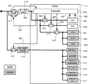
図5は、実施形態1に係る画像形成装置10が第1スリープ状態のときの通電状態を説明するブロック図である。尚、図5において図4と共通する部分は同じ参照番号で示している。
FIG. 5 is a block diagram illustrating an energized state when the
この第1スリープ状態では、操作部I/F305、画像処理部309、スキャナ画像処理部310、スキャナI/F311、プリンタ画像処理部312、プリンタI/F313への電力供給が停止されている。
In the first sleep state, power supply to the operation unit I /
第2スリープ状態では、参照番号301,303〜305及び309〜313で示す部分への電力供給を遮断するとともに、RAM302、LANコントローラ306及び電源制御部320に電力を供給し続ける制御をする(通電状態を図6に示す)。
In the second sleep state, power supply to the portions indicated by
図6は、実施形態1に係る画像形成装置10が第2スリープ状態のときの通電状態を説明するブロック図である。尚、図6において図4と共通する部分は同じ参照番号で示している。
FIG. 6 is a block diagram illustrating an energized state when the
この第2スリープ状態では、図5で非通電状態にある部分に加えて、CPU301,ROM303,HDD304への電力供給が停止されている。
In the second sleep state, power supply to the
スタンバイ状態から第2スリープ状態へ移行する場合、電源制御部320は、参照番号301,303〜305及び309〜313で示す部分に供給されている電力を遮断するように制御する。第2スリープ状態においても一部の受信パケット(ARP(Address Resolution Protocol)等)に関しては、LANコントローラ306で応答することが可能である。しかしながら、全ての受信パケットに対してLANコントローラ306が応答することはできない。LANコントローラ306で応答できないパケットを受信した場合には、CPU301を動作可能な状態に復帰させる必要があり、第2スリープ状態では受信パケットに対する応答が遅くなってしまうことがある。
When shifting from the standby state to the second sleep state, the power
Wake1信号(第1復帰信号)402は、第2スリープ状態になっている場合に、LANコントローラ306がネットワーク60経由でジョブパケットを受信した際に、その旨をLANコントローラ306から電源制御部320に通知するための信号である。電源制御部320は、このWake1信号402を検知すると、制御信号404〜408を制御して、各部に対して供給する電源のオフ/オン制御を行う。
The Wake 1 signal (first return signal) 402 is sent from the
Wake2信号(第2復帰信号)403は、LANコントローラ306が、第2スリープ状態のときに、ネットワーク60から、ジョブパケットでなく、かつ代理応答可能パケットでもないパケットを受信した際に出力する。尚、このパケットは、例えば画像形成装置10の状態の問い合わせ等である。このパケットを受信するとLANコントローラ306は、その旨を電源制御部320に通知するためにWake2信号403を出力する。電源制御部320は、Wake2信号403を検知すると制御信号404〜408を制御し、各部に対して供給する電源の選択を行う。制御信号404〜408は、各部に対して電源供給を行うかどうかを制御するための信号である。
The Wake 2 signal (second return signal) 403 is output when the
またスイッチ411〜415は、制御信号404〜408で制御されるスイッチである。電源制御部320がスイッチ411〜415のオン/オフを制御信号404〜408で制御することで、各部に対する電源供給状態を変更することが可能となる。スイッチ411〜415は、FETやリレースイッチ等によって実現することができる。
The
制御信号404とスイッチ413は、LANコントローラ306への電源供給を制御する。スイッチ413は、画像形成装置10がスタンバイ状態やスリープ状態の場合に、LANコントローラ306へ電源を供給し、画像形成装置10がオフ状態の場合にはLANコントローラ306への電源を停止するように制御している。即ち、スイッチ413は、第一電源供給部409からLANコントローラ306への電力の供給及び停止を切り替える。
A
制御信号405とスイッチ414は、RAM302への第一電源供給を制御する。スイッチ414は、画像形成装置10がスタンバイ状態やスリープ状態の場合にRAM302へ電源を供給し、画像形成装置10がオフ状態の場合にはRAM302への電源供給を停止するように制御している。即ち、スイッチ414は、第一電源供給部409からRAM302への電力の供給及び停止を切り替える。
The
制御信号406とスイッチ415は、CPU301,ROM303及びHDD304への第一電源供給を制御する。即ち、スイッチ415は、第一電源供給部409からCPU301,ROM303及びHDD304への電力の供給と停止を切り替える。制御信号406は、画像形成装置10がスタンバイ状態或いは第1スリープ状態の場合に、CPU301,ROM303及びHDD304へ電源を供給する。また画像形成装置10が第2スリープ状態やオフ状態の場合は、CPU301,ROM303及びHDD304への電源の供給を停止するように制御している。即ち、スイッチ415は、第一電源供給部409からCPU301,ROM303及びHDD304への電力の供給と停止を切り替える。
A
制御信号407とスイッチ411は、第一電源供給部409に対してAC電源の供給を制御する。制御信号407とスイッチ411は、後述の電源スイッチ401がオンされると、電源制御部320によってオンされる。これにより、ユーザが電源スイッチ401をオフした際にも、制御部11に対して電源供給することが可能となる。このとき電源制御部320は、スイッチ401のオフ/オンを取得するための信号416により、スイッチ401がオフされたことを検知する。そして、それをCPU301に通知することで、正常なシャットダウン処理をしてから各部への電源供給をオフすることが可能となる。電源スイッチ401は、ユーザが画像形成装置10への電源オン/オフの操作をするための電源スイッチであり、ユーザが電源スイッチ401をオンすることで第一電源供給部409にAC電源が供給される。
The
制御信号408とスイッチ412は、第二電源供給部410に対してAC電源の供給を制御する。また制御信号408とスイッチ412は、各部への第2電力の供給を制御する。例えば、画像処理部309への電源供給で説明すると、スリープ状態の場合はスイッチ412はオフされて電力供給は停止されていて、スタンバイ時にはスイッチ412はオンされて第二電源供給部410に電力供給される。即ち、スイッチ412は、電源制御部320によりオン/オフが制御され、第二電源供給部410からの第2電力の供給及び停止を切り替える。
The
第一電源供給部409は、AC電源をDC電源に変換し、電源制御部320等に対して第1電力を供給する。第一電源供給部409から供給される第1電力は、画像形成装置10がスリープ状態に移行した場合でも、電源制御部320等に対して供給されている。またこの第1電力は、電源制御部320の他にスリープ状態からの復帰を行うために、ネットワーク60からの着信検知をするためのLANコントローラ306へも供給されている。
The first
第二電源供給部410は、AC電源をDC電源に変換し、各デバイスに対して、第2電力を供給する。第二電源供給部410から供給される第2電力は、画像形成装置10がスリープ状態の時に供給が停止される。第二電源供給部410は、スリープ状態の場合は消費電力を少なくして、スリープ状態の場合に電源供給が不要な各部への電源供給を制御するために備えられている。
The second
図7は、実施形態1に係る画像形成装置10のLANコントローラ(LANC)306の構成をより詳細に説明するブロック図である。
FIG. 7 is a block diagram illustrating in more detail the configuration of the LAN controller (LANC) 306 of the
LANコントローラ306は、処理の機能としてみるとWake On LAN(以降、WOL)パターン検出部701、代理応答パターン検出部702、代理応答送信パケット処理部703、データ転送処理部704、ROM705を有している。さらにROM705は、WOLパターン登録領域706、代理応答パケット登録領域707、代理応答送信データ登録領域708を有している。WOLパターン登録領域706は、WOLパケットのパターンを登録している。WOLパターン検出部701は、受信したパケットのパターンが、この登録されているWOLパケットのパターンと一致すると、WOLパケットを受信したと判定する。代理応答パケット登録領域707は、LANC306が代理応答できるパケットのパターンを登録している。代理応答パターン検出部702は、受信したパケットのパターンが、この登録されている代理応答パケットのパターンと一致すると、LANC306で代理応答できるパケットであると判定する。代理応答送信データ登録領域708は、代理応答送信パケット処理部703が送信するパケットデータを登録している。代理応答送信データ登録領域708は、代理応答時に、LANC306が送信するパケットパターンを登録している。
The
WOLパターン検出部701は、CPU301がスリープモード中に、ネットワーク60から受信したパケットのパターンと、WOLパターン登録領域706に記憶されているパターンとを比較する。そしてこの比較の結果、これらが一致した場合は、CPU301へ割り込みなどの出力を行ってCPU301を起動させる。また第2スリープモードにおいて、LANコントローラ306だけで処理できないパケット、例えば印刷ジョブのパケットをWOLパターンとして検出すると、画像形成装置10をスリープ状態から復帰させる。
The WOL
代理応答パターン検出部702は、CPU301がスリープモード中に、代理応答パケット登録領域707に登録されているパターンと、ネットワーク60から受信したパケットのパターンとを比較する。この比較の結果、これらが一致した場合は、代理応答送信パケット処理部703へ通知して、代理応答送信データ登録領域708に登録されているパケットパターンで、ネットワーク60へパケットを送出させる。また代理応答送信パケット処理部703は、ネットワーク60へパケットを送出する際、相手先のアドレスの生成や、パケットのチェックサム等の計算を行って、そのパケットに、それら情報を付加することもできる。第2スリープモードにおいてLANコントローラ306で処理可能なパケット、例えばARPを代理応答パケットとして検出すると、スリープモードの状態を維持したまま、LANコントローラ306で応答する。
The proxy response
データ転送処理部704は、CPU301からの指示により、ネットワーク60から受信したデータをRAM302へ転送する、またはRAM302にあるデータをネットワーク60へ送信するための処理を行う。
The data
図8は、実施形態1に係る画像形成装置10が受信するパケットの一例を示す図である。
FIG. 8 is a diagram illustrating an example of a packet received by the
パケットの先頭部分は、EtherFrame801,IPFrame802,UDPFrame803を有し、その後にSNMP(Simple Network Management Protocol)などのパケットの種類によって変化する領域を含んでいる。後述のフローチャートにおけるパケットの解析は、受信したパケットの図8に示した領域を比較することによって行われる。例えば、画像形成装置10が第2スリープ状態の場合は、LANコントローラ306は宛先のEtherAddress804と自機アドレスとを比較して自機宛てのパケットかどうかを判定する。そして自機宛のパケットであると判定すると画像形成装置10を通常状態に復帰させる場合、或いは「XXX Frame」に示した領域に特定のデータ列が検出された場合に通常状態に復帰させる場合、LANC306はWake1信号402をアサートする。これにより電源制御部320は、各部に電力が供給するように制御信号によりスイッチをオンさせて、通常状態に復帰させる。
The head portion of the packet has
また、代理応答を行う場合も、代理応答パケット登録領域707に登録されているパターンと、受信したパケットとを比較し、代理応答すべきとパケットであると判定すると、ネットワーク60に代理応答を返す。尚、図8に示すパケットの構成はあくまでも一例であり、IPV4、IPV6などによってパケットのフォーマットは変化する。
Also, when a proxy response is made, the pattern registered in the proxy response packet registration area 707 is compared with the received packet, and if it is determined that the proxy response should be a packet, the proxy response is returned to the
図9は、実施形態1に係る画像形成装置10がスリープモードに移行するときの処理を説明するフローチャートである。尚、この処理を実行するプログラムはROM303或いはHDD304に記憶されており、実行時にRAM302に展開され、CPU301がそのプログラムを実行することにより、このフローチャートで示す処理が実現される。
FIG. 9 is a flowchart illustrating processing when the
先ずS901でCPU301は、LAN60経由でパケットを受信したかどうかを判定する。ここでCPU301がパケットを受信したと判定するとS902に処理を進め、パケットを受信していないと判定した場合はS906に処理を進める。S902でCPU301は、S901で受信したパケットがWOLパケットであるかどうかを判定し、WOLパケットであると判定した場合はS903に処理を進め、そうでないときはS906に処理を進める。ここでWOLパケットかどうかの判定基準は、第2スリープ状態のときに、LANコントローラ306で応答可能な場合にはWOLパケットではないと判定し、それ以外のCPU301で応答する必要がある場合にはWOLパケットであると判定する。第2スリープ状態のときにLANコントローラ306が応答可能なパケットの一例として、例えばARPがある。
In step S <b> 901, the
S903でCPU301は、WOLパケットの受信時間間隔を測定するためにタイマ314による計時を開始する。このタイマ314は、スリープモードに移行する場合に、第1スリープモードに移行させるか、第2スリープモードに移行させるかをCPU301が判定するための判断材料を提供する。即ち、ここでは、受信時間間隔が所定時間未満のときは第1スリープ状態に移行し、受信時間間隔が所定時間以上のときは、より消費電力の少ない第2スリープ状態に移行するようにしている。
In step S903, the
次にS904に進みCPU301は、LAN60経由で受信したパケットがWOLパケットであるかどうかを判定する。ここでWOLパケットであると判定した場合はS905に遷移し、そうでないと判定した場合はS907に遷移する。S905でCPU301は、S903で計時動作を開始したタイマ314の計時値を、例えばRAM302に記憶してS903に処理を進める。ここで記録するタイマ314の計時値は、WOLパケットを受信してから、次にWOLパケットを受信するまでの時間間隔を示す。
In step S904, the
S906でCPU301は、スリープモードへ移行する移行条件を満足したかどうかを判定する。この移行条件は、例えば、装置が動作しない経過時間が、スリープモードに移行する条件である経過時間に到達したか、或いはユーザがスリープモードへの遷移を指示するスイッチを操作した場合等がある。S906でCPU301が、スリープモードへ移行可能と判定した場合はS909に進み、CPU301は、画像形成装置10を第2スリープモードに移行するための処理を行って、この処理を終了する。一方、S906でCPU301が、スリープモードへの移行条件を満足していないと判定した場合はS901に処理を進める。
In step S <b> 906, the
S907でCPU301は、スリープモードへ移行する移行条件が満足されたかどうかを判定する。このスリープモードへの移行条件は、例えば、装置が動作しない経過時間が、スリープモードに移行する条件である経過時間に到達したか、或いはユーザがスリープモードへの遷移を指示するスイッチを操作した場合等がある。S907でCPU301が、スリープモードへの移行条件を満足したと判定した場合はS908に処理を進め、スリープモードへ移行条件を満足していないと判定した場合はS904に処理を進める。
In step S907, the
S908でCPU301は、S905で保持したタイマ314による計時値、即ち、WOLパケットの受信時間間隔が、閾値以上かどうかを判定する。ここでWOLパケットの受信時間間隔が閾値以上と判定すると前述したS909に処理を進めて、画像形成装置10を第2スリープモードに移行するが、そうでないときはS910に処理を進める。ここでの閾値は、ユーザが、例えば操作部12を介して設定できるようにしてもよい。また、閾値のデフォルトを「0」とし、当初は、どのような環境であっても第2スリープモードに移行するように設定しておいて、ユーザに対して、受信パケットに対する応答が早くなるようなモードを推奨するような構成にしても良い。
In step S908, the
更に、S908でCPU301が、第1スリープモードに移行すると判定した場合は、ユーザに対して、より低消費電力の第2スリープモードに移行していないことを示すアラートを操作部12に表示するようにしても良い。
Furthermore, when the
S910でCPU301は、画像形成装置10を第1スリープモードに移行するための処理を行う。このS910の処理は、S908でWOLパケットの受信時間間隔が閾値以下の短い場合で、スリープモードへの移行条件を満足したときに実行される。これにより、WOLパケットの受信時間間隔が所定値よりも短い場合は、画像形成装置10は、より受信パケットに対する応答性が早い第1スリープモードへ遷移できる。
In step S910, the
このようにWOLパケットの受信時間間隔に基づき、スリープモードに移行するときのスリープ状態を切り替えることにより、ユーザへの利便性を残しつつ、低消費電力のスリープモードに移行させることが可能となる。 As described above, by switching the sleep state when shifting to the sleep mode based on the reception time interval of the WOL packet, it is possible to shift to the sleep mode with low power consumption while maintaining convenience for the user.
[実施形態2]
上述の実施形態1では、WOLパケットの受信間隔によってスリープモードへの移行時に遷移させるスリープモードを選択する例について説明した。これに対して実施形態2では、WOLパケットであり、且つ定期的に応答する必要があるパケットの受信間隔によって、スリープモードに移行するときに遷移するスリープモードを選択する例について説明する。尚、実施形態2に係る画像形成装置10,20の構成や、画像形成装置10,20やPC40,50を含むシステム構成も、前述の実施形態1と同じであるため、その説明を省略する。
[Embodiment 2]
In the above-described first embodiment, the example in which the sleep mode to be shifted at the time of transition to the sleep mode is selected according to the reception interval of the WOL packet has been described. On the other hand, in the second embodiment, an example will be described in which a sleep mode that transitions when shifting to the sleep mode is selected according to a reception interval of a packet that is a WOL packet and needs to be periodically responded. Note that the configuration of the
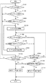
図10は、本発明の実施形態2に係る画像形成装置10がスリープモードに移行するときの処理を説明するフローチャートである。尚、この処理を実行するプログラムはROM303或いはHDD304に記憶されており、実行時にRAM302に展開され、CPU301がそのプログラムを実行することにより、このフローチャートで示す処理が実現される。
FIG. 10 is a flowchart illustrating processing when the
まずS1001でCPU301は、LAN60経由でパケットを受信したかどうかを判定する。ここでパケットを受信したと判定した場合はS1002に処理を進め、受信していないと判定した場合はS1008に処理を進める。S1002でCPU301は、S1001で受信したパケットがWake On LAN(以降、WOL)パケットかどうかを判定する。ここでCPU301がWOLパケットと判定した場合はS1003に処理を進め、そうでないときはS1008に処理を進める。ここでWOLパケットかどうかの判定基準は、第2スリープ状態のときに、LANコントローラ306で応答可能な場合はWOLパケットではないと判定し、それ以外のCPU301で応答する必要がある場合にはWOLパケットであると判定する。第2スリープ状態のときにLANコントローラ306が応答可能なパケットの一例として、例えばARPがある。
In step S <b> 1001, the
S1003でCPU301は、S1001で受信したパケットが定期的に受信する可能性のあるパケットかどうかを判定する。ここで定期的に受信するパケットであると判定するとS1004に処理を進め、そうでないときはS1008に処理を進める。定期的に受信する可能性のあるパケットとしては、例えばSNMPパケットが考えられる。
In step S1003, the
ここでは前述の図8に記載の宛先ポート番号805を確認してSNMPパケットかどうかを判定し、「XXX Frame」内のObejcts ID(不図示)が代理応答できないIDである場合に、定期的に受信するパケットであると判定する。
Here, the
S1004でCPU301は、定期的に受信すると判定したパケットの受信時間間隔を測定するためにタイマ314による計時動作を開始する。このタイマ314は、スリープモードに移行する場合に、第1スリープモードに移行させるか、第2スリープモードに移行させるかをCPU301が判定するための時間間隔を計時する。次にS1005に進みCPU301は、受信したパケットがWOLパケットかどうかを判定する。ここでWOLパケットであると判定した場合はS1006に処理を進め、そうでないときはS1009に処理を進める。S1006でCPU301は、S1003と同様に、受信したパケットが定期的に受信する可能性のあるパケットかどうかを判定する。ここで定期的に受信するパケットであると判定するとS1007に処理を進め、そうでないと判定した場合はS1009に処理を進める。ここで、定期的に受信する可能性のあるパケットとしては、例えばSNMPパケットが考えられる。
In step S <b> 1004, the
S1007でCPU301は、S1004で計時動作を開始したタイマによる計時値をRAM302に記憶する。ここでRAM302に記憶する計時値は、定期的に受信する可能性のあるパケットを受信してから、次に、その定期的に受信する可能性のあるパケットを受信するまでの時間間隔を示す。本実施形態2では、スリープモードに移行する際、第1スリープモード、第2スリープモードのいずれに移行するかは、このタイマ314により計時された時間間隔に基づいてCPU301が判定する。
In step S <b> 1007, the
S1008でCPU301は、スリープモードへ移行する移行条件を満足したかどうかを判定する。このスリープモードに移行する移行条件としては、画像形成装置10が動作しない経過時間がスリープモードに移行する時間になったか、或いはユーザが、スリープモードに移行させるスイッチを操作したか等がある。ここでCPU301は、スリープモードへの移行条件が満たされたと判定するとS1011に処理を進め、スリープモードへの移行条件を満たしていないと判定した場合はS1001に処理を進める。S1011でCPU301は、画像形成装置10を第2スリープモードに移行するための処理を行う。これは定期的に受信するパケットの受信時間間隔が閾値以上である場合や、WOLパケットやWOLパケットでも定期的に受信する可能性のあるパケットを受信していない状態で、スリープモードへの移行条件が満たされた場合に実行される。
In step S1008, the
S1009でCPU301は、スリープモードへの移行条件が満たされたかどうかを判定する。このスリープモードに移行する移行条件としては、画像形成装置10が動作しない経過時間がスリープモードに移行する時間になったか、或いはユーザが、スリープモードに移行させるスイッチを操作したか等がある。ここでCPU301は、スリープモードへ移行する移行条件を満足したと判定するとS1010に処理を進め、そうでないときはS1005に処理を進める。S1010でCPU301は、S1007でRAM302に記憶した計時値、即ち、定期的に受信する可能性のあるパケットの受信時間間隔が閾値以上かどうかを判定する。ここで、そのパケットの受信時間間隔が閾値以上と判定するとS1011に処理を進めて、画像形成装置10を第2スリープ状態に移行させる。一方、S1010で、定期的に受信する可能性のあるパケットの受信時間間隔が閾値未満と判定したときはS1012に処理を進めて、画像形成装置10を第1スリープ状態に移行させる。
In step S1009, the
これにより定期的に受信する可能性のあるパケットの受信時間間隔が長い場合や、WOLパケットやWOLパケットでも、定期的に受信する可能性のあるパケットを受信していない場合、画像形成装置10はより消費電力の少ない第2スリープ状態に遷移できる。尚、ここでの閾値は、ユーザが任意に設定できるようにしても良い。
As a result, when the reception time interval of a packet that may be received regularly is long, or when a WOL packet or a WOL packet is not received, the
また、デフォルトの閾値を「0」とし、最初は、どのような環境であっても第2スリープ状態に移行するようにしておき、ユーザに対して、受信パケットに対する応答が早くなるようなモードを推奨するような構成にしてもよい。 In addition, the default threshold is set to “0”, and at first, the mode is set so as to shift to the second sleep state in any environment so that the response to the received packet is made faster for the user. It may be configured as recommended.
更に、第1スリープ状態に移行すると判定した場合は、ユーザに対して、より消費電力の少ない第2スリープ状態に移行していないことを示すアラートを表示するようにしても良い。 Further, when it is determined that the transition to the first sleep state is made, an alert indicating that the transition to the second sleep state with less power consumption is not made may be displayed to the user.
また画像形成装置10を第1スリープ状態に移行するための処理は、定期的に受信する可能性のあるパケットの受信時間間隔が閾値以下の場合や、スリープモードへの移行が発生したときに実行される。これにより定期的に受信する可能性のあるパケットの受信時間間隔が短い場合は、画像形成装置10は、より受信パケットに対する応答性の早い第1スリープ状態に移行できるようになる。
Further, the process for shifting the
このようにWOLパケットで、且つ、定期的に受信する可能性のあるパケットの受信時間間隔に基づいて、スリープモードに移行するときのスリープ状態を切り替えられる。こうすることにより、ユーザへの利便性を残しつつ、低消費電力となるスリープ状態に移行させることが可能となる。 In this way, the sleep state when shifting to the sleep mode can be switched based on the reception time interval of the WOL packet and the packet that may be received periodically. By doing so, it is possible to shift to a sleep state where power consumption is low while leaving convenience to the user.
[実施形態3]
次に本発明の実施形態3を説明する。実施形態3では、ユーザは、画像形成装置10がスリープモードに移行する際、前述の第1スリープ状態か、第2スリープ状態のいずれかに移行するかを予め設定できるものとする。そして画像形成装置10は、上述のスリープモードへの移行条件を満足したと判定すると、そのユーザの設定に従って、第1スリープ状態、或いは第2スリープ状態に移行する。また画像形成装置10は、前述の実施形態1,2のように、パケットの受信時間間隔を計測し、その時間間隔が所定時間よりも長い場合で、且つ、上述のユーザの設定が第1スリープ状態である場合は、第2スリープ状態への移行を推奨する。尚、実施形態3に係る画像形成装置10,20の構成や、画像形成装置10,20やPC40,50を含むシステム構成も、前述の実施形態1と同じであるため、その説明を省略する。
[Embodiment 3]
Next, Embodiment 3 of the present invention will be described. In the third embodiment, when the
図11(A)は、画像形成装置10がスリープモードに移行する際、前述の第1スリープ状態か、第2スリープ状態のいずれかに移行するかを、ユーザに予め設定させるために操作部12の表示部に表示される画面例を示す図である。
FIG. 11A illustrates an
ここではラジオボタン1101又は1102により、第1スリープ状態、或いは第2スリープ状態に移行するように設定できる。この画面で設定された内容がRAM302に記憶される。
Here, the
図12は、本発明の実施形態3に係る画像形成装置10がスリープモードに移行するときの処理を説明するフローチャートである。尚、この処理を実行するプログラムはROM303或いはHDD304に記憶されており、実行時にRAM302に展開され、CPU301がそのプログラムを実行することにより、このフローチャートで示す処理が実現される。図12において、図10と共通する処理は同じ記号で示し、それらの説明を省略する。
FIG. 12 is a flowchart illustrating processing when the
S1008或いはS1009でスリープモードに移行する条件を満足したと判定するとS1201に進む。S1201でCPU301は、図11(A)の画面を介して設定されたスリープモードをRAM302から読出し、その設定が第1スリープ状態であるか、第2スリープ状態であるかを判定する。ここで第2スリープ状態に設定されていると判定するとS1011に進み、画像形成装置10を第2スリープ状態に移行させる。
If it is determined in S1008 or S1009 that the condition for shifting to the sleep mode is satisfied, the process proceeds to S1201. In S1201, the
一方、S1201でCPU301が、第1スリープ状態が設定されていると判定するとS1010に進み、定期的に受信する可能性のあるパケットの受信時間間隔が閾値よりも長いかどうかを判定する。ここで定期的に受信する可能性のあるパケットの受信時間間隔が閾値よりも短いと判定したときはS1012に処理を進めて、画像形成装置10を第1スリープ状態に移行させる。一方、S1010でCPU301が、パケットの受信時間間隔が閾値よりも長いと判定するとS1202に進む。S1202でCPU301は、操作部12の表示部に、例えば図11(B)に示すような画面を表示する。
On the other hand, if the
図11(B)は、第1スリープ状態が設定されているときに、より消費電力の少ない第2スリープ状態に移行するように変更するかどうかをユーザに問う画面例を示す。 FIG. 11B shows an example of a screen asking the user whether to change to the second sleep state with lower power consumption when the first sleep state is set.
S1203でCPU301は、図11(B)の画面で、ボタン1110,1111のいずれが押下されるかを判別する。ここでユーザが「はい」ボタン1110を押下するとS1203からS1011に進んで、画像形成装置10を第2スリープ状態に移行させる。一方、ユーザが「いいえ」ボタン1111が押下すると、S1203からS1012に進んで、画像形成装置10を第1スリープ状態に移行させる。
In step S1203, the
実施形態3によれば、画像形成装置10は、パケットの受信時間間隔を測定し、その受信時間間隔が所定値よりも長いときは、ユーザが設定しているスリープモードよりも、より消費電力の少ないスリープモードを設定するようにユーザに推奨できる。
According to the third embodiment, the
また、実施形態3では図面で説明していないが、例えば逆に、ユーザの設定が第2スリープ状態でパケットの受信時間間隔が所定値よりも短いときは、パケットに対する応答性を低下させないように、第1スリープ状態を設定するようにユーザに推奨しても良い。 Further, although not described in the drawings in Embodiment 3, for example, conversely, when the user setting is in the second sleep state and the packet reception time interval is shorter than a predetermined value, the response to the packet is not reduced. The user may be recommended to set the first sleep state.
また移行するスリープモードの決定を、ユーザの設定、或いは画像形成装置の決定のいずれかを優先させるモードを設けても良い。そしてユーザの設定を優先させる場合は、パケットの受信時間間隔に依らずに、ユーザの設定に従うようにしても良い。 In addition, a mode may be provided that prioritizes either the user setting or the image forming apparatus determination in determining the sleep mode to be transferred. If priority is given to user settings, the user settings may be followed regardless of the packet reception time interval.
なお、上述した実施形態における各種データの構成及びその内容は、これに限定されるものではなく、用途や目的に応じて、様々な構成や内容で構成されることは言うまでもない。 It should be noted that the configuration and contents of various data in the above-described embodiments are not limited to this, and it goes without saying that the various data and configurations are configured according to applications and purposes.
以上、実施形態について示したが、本発明は、例えば、システム、装置、方法、プログラムもしくは記憶媒体等としての実施態様をとることが可能である。具体的には、複数の機器から構成されるシステムに適用しても良いし、また、一つの機器からなる装置に適用しても良い。また、上記各実施形態を組み合わせた構成も全て本発明に含まれるものである。 Although the embodiment has been described above, the present invention can take an embodiment as a system, apparatus, method, program, storage medium, or the like. Specifically, the present invention may be applied to a system composed of a plurality of devices, or may be applied to an apparatus composed of a single device. Moreover, all the structures which combined said each embodiment are also contained in this invention.
(その他の実施形態)
本発明は、上述の実施形態の1以上の機能を実現するプログラムを、ネットワーク又は記憶媒体を介してシステム又は装置に供給し、そのシステム又は装置のコンピュータにおける1つ以上のプロセッサーがプログラムを読出し実行する処理でも実現可能である。また、1以上の機能を実現する回路(例えば、ASIC)によっても実現可能である。
(Other embodiments)
The present invention supplies a program that realizes one or more functions of the above-described embodiments to a system or apparatus via a network or a storage medium, and one or more processors in a computer of the system or apparatus read and execute the program This process can be realized. It can also be realized by a circuit (for example, ASIC) that realizes one or more functions.
本発明は上記実施の形態に制限されるものではなく、本発明の精神及び範囲から離脱することなく、様々な変更及び変形が可能である。従って、本発明の範囲を公にするために、以下の請求項を添付する。 The present invention is not limited to the above-described embodiment, and various changes and modifications can be made without departing from the spirit and scope of the present invention. Therefore, in order to make the scope of the present invention public, the following claims are attached.
10,20,30…画像形成装置、12…操作部、301…CPU、306…LANコントローラ、320…電源制御部、409…第一電源供給部、410…第二電源供給部
DESCRIPTION OF
Claims (13)
スリープモードに移行する条件を満足したかどうかを判定する判定手段と、
特定のパケットの受信時間間隔を計時する計時手段と、
前記計時手段により計時した前記受信時間間隔に基づいて、前記複数のスリープモードのいずれに移行するかを決定する決定手段と、
前記判定手段が前記条件を満足したと判定すると、前記決定手段により決定されたスリープモードに移行するように制御する制御手段と、
を有することを特徴とする情報処理装置。 An information processing apparatus having a plurality of sleep modes,
A determination means for determining whether or not a condition for shifting to the sleep mode is satisfied;
A time measuring means for measuring a reception time interval of a specific packet;
Determining means for determining which of the plurality of sleep modes to transition to based on the reception time interval timed by the time measuring means;
Control means for controlling to shift to the sleep mode determined by the determination means when the determination means determines that the condition is satisfied;
An information processing apparatus comprising:
前記複数のスリープモードのうち、いずれのスリープモードを前記情報処理装置に適用するかをユーザの指示に従って選択する選択手段と、
スリープモードに移行する条件を満足したかどうかを判定する第1の判定手段と、
前記第1の判定手段が前記条件を満足したと判定すると、前記選択手段によって選択されているスリープモードに移行するように制御する制御手段と、
特定のパケットの受信時間間隔を計時する計時手段と、
前記情報処理装置に適用するスリープモードを、前記選択手段によって選択されているスリープモードから他のスリープモードに変更するようにユーザに促すか否かを、前記計時手段により計時した前記受信時間間隔に基づいて判定する第2の判定手段と、
ユーザに促すと前記第2の判定手段によって判定された場合に、前記情報処理装置に適用するスリープモードを変更するようにユーザに促す通知手段と、
を有することを特徴とする情報処理装置。 An information processing apparatus having a plurality of sleep modes,
Selecting means for selecting which sleep mode of the plurality of sleep modes to apply to the information processing apparatus according to a user instruction;
First determination means for determining whether or not a condition for shifting to the sleep mode is satisfied;
Control means for controlling to shift to the sleep mode selected by the selection means when the first determination means determines that the condition is satisfied;
A time measuring means for measuring a reception time interval of a specific packet;
Whether or not to prompt the user to change the sleep mode applied to the information processing apparatus from the sleep mode selected by the selection unit to another sleep mode is set in the reception time interval measured by the timing unit. Second determination means for determining based on;
A notification unit that prompts the user to change a sleep mode to be applied to the information processing apparatus when the second determination unit determines to prompt the user;
An information processing apparatus comprising:
判定手段が、スリープモードに移行する条件を満足したかどうかを判定する判定工程と、
計時手段が、特定のパケットの受信時間間隔を計時する計時工程と、
決定手段が、前記計時工程で計時した前記受信時間間隔に基づいて、前記複数のスリープモードのいずれに移行するかを決定する決定工程と、
制御手段が、前記判定工程が前記条件を満足したと判定すると、前記決定工程で決定されたスリープモードに移行するように制御する制御工程と、
を有することを特徴とする情報処理装置の制御方法。 A method for controlling an information processing apparatus having a plurality of sleep modes,
A determination step of determining whether the determination means satisfies a condition for shifting to the sleep mode;
A time measuring step in which a time measuring means measures a reception time interval of a specific packet;
A determining step for determining which of the plurality of sleep modes to be shifted based on the reception time interval timed in the time counting step;
When the control means determines that the determination step satisfies the condition, a control step for controlling to shift to the sleep mode determined in the determination step;
A method for controlling an information processing apparatus, comprising:
選択手段が、前記複数のスリープモードのうち、いずれのスリープモードを前記情報処理装置に適用するかをユーザの指示に従って選択する選択工程と、
第1の判定手段が、スリープモードに移行する条件を満足したかどうかを判定する第1の判定工程と、
制御手段が、前記第1の判定工程が前記条件を満足したと判定すると、前記選択工程で選択されているスリープモードに移行するように制御する制御工程と、
計時手段が、特定のパケットの受信時間間隔を計時する計時工程と、
第2の判定手段が、前記情報処理装置に適用するスリープモードを、前記選択工程で選択されているスリープモードから他のスリープモードに変更するようにユーザに促すか否かを、前記計時工程で計時した前記受信時間間隔に基づいて判定する第2の判定工程と、
ユーザに促すと前記第2の判定工程で判定された場合に、前記情報処理装置に適用するスリープモードを変更するようにユーザに促す通知工程と、
を有することを特徴とする情報処理装置の制御方法。 A method for controlling an information processing apparatus having a plurality of sleep modes,
A selection step in which the selection unit selects which sleep mode of the plurality of sleep modes to apply to the information processing apparatus according to a user instruction;
A first determination step for determining whether or not the first determination means satisfies a condition for shifting to the sleep mode;
When the control means determines that the first determination step satisfies the condition, a control step for controlling to shift to the sleep mode selected in the selection step;
A time measuring step in which a time measuring means measures a reception time interval of a specific packet;
Whether the second determination means prompts the user to change the sleep mode to be applied to the information processing apparatus from the sleep mode selected in the selection step to another sleep mode in the timing step. A second determination step for determining based on the measured reception time interval;
A notification step that prompts the user to change a sleep mode to be applied to the information processing apparatus when prompted by the second determination step when prompting the user;
A method for controlling an information processing apparatus, comprising:
Priority Applications (2)
| Application Number | Priority Date | Filing Date | Title |
|---|---|---|---|
| JP2015082857A JP2016201077A (en) | 2015-04-14 | 2015-04-14 | Information processing unit, control method thereof, and program |
| US15/088,774 US10078360B2 (en) | 2015-04-14 | 2016-04-01 | Information processing apparatus, method of controlling the same, and storage medium |
Applications Claiming Priority (1)
| Application Number | Priority Date | Filing Date | Title |
|---|---|---|---|
| JP2015082857A JP2016201077A (en) | 2015-04-14 | 2015-04-14 | Information processing unit, control method thereof, and program |
Publications (1)
| Publication Number | Publication Date |
|---|---|
| JP2016201077A true JP2016201077A (en) | 2016-12-01 |
Family
ID=57128809
Family Applications (1)
| Application Number | Title | Priority Date | Filing Date |
|---|---|---|---|
| JP2015082857A Pending JP2016201077A (en) | 2015-04-14 | 2015-04-14 | Information processing unit, control method thereof, and program |
Country Status (2)
| Country | Link |
|---|---|
| US (1) | US10078360B2 (en) |
| JP (1) | JP2016201077A (en) |
Families Citing this family (2)
| Publication number | Priority date | Publication date | Assignee | Title |
|---|---|---|---|---|
| US10769095B2 (en) * | 2016-07-20 | 2020-09-08 | Canon Kabushiki Kaisha | Image processing apparatus |
| JP7238561B2 (en) * | 2019-04-11 | 2023-03-14 | 京セラドキュメントソリューションズ株式会社 | Information processing device and packet pattern generation program |
Family Cites Families (7)
| Publication number | Priority date | Publication date | Assignee | Title |
|---|---|---|---|---|
| JP4639952B2 (en) | 2005-05-23 | 2011-02-23 | 富士ゼロックス株式会社 | Network terminal device, energy saving mode setting method thereof, and energy saving mode setting program |
| US8077712B2 (en) * | 2008-06-12 | 2011-12-13 | Cisco Technology, Inc. | Static neighbor wake on local area network |
| US20110261405A1 (en) * | 2010-04-23 | 2011-10-27 | Konica Minolta Business Technologies, Inc. | Information processing terminal and power state management apparatus |
| TWI421675B (en) * | 2010-07-21 | 2014-01-01 | Mstar Semiconductor Inc | Automatic mode switch portable electronic device |
| JP5808129B2 (en) * | 2011-04-06 | 2015-11-10 | キヤノン株式会社 | Image forming apparatus and method for controlling image forming apparatus, |
| JP5799699B2 (en) * | 2011-09-15 | 2015-10-28 | 富士ゼロックス株式会社 | Power supply control device, management control device, image processing device, power supply control program |
| JP2014085955A (en) * | 2012-10-25 | 2014-05-12 | Canon Inc | Image forming apparatus, and information processing method and program |
-
2015
- 2015-04-14 JP JP2015082857A patent/JP2016201077A/en active Pending
-
2016
- 2016-04-01 US US15/088,774 patent/US10078360B2/en not_active Expired - Fee Related
Also Published As
| Publication number | Publication date |
|---|---|
| US20160306413A1 (en) | 2016-10-20 |
| US10078360B2 (en) | 2018-09-18 |
Similar Documents
| Publication | Publication Date | Title |
|---|---|---|
| JP6618570B2 (en) | Printing apparatus and printing apparatus control method | |
| JP4830007B2 (en) | Image forming apparatus | |
| US9846560B2 (en) | Information processing apparatus capable of selecting among a plurality of power saving modes using a simple operation, and control method and storage medium therefor | |
| JP5216540B2 (en) | Image forming apparatus | |
| JP2009239870A (en) | Communication apparatus, control method therefor, program, and storage medium | |
| KR20130037113A (en) | Method and apparatus for controlling link speed of image forming apparatus | |
| JP2016082252A (en) | Image forming apparatus, control method, and program | |
| JP2011071760A (en) | Information processing apparatus, job processing method thereof, and program | |
| WO2013175728A1 (en) | Image forming apparatus, method for controlling image forming apparatus, and program | |
| US9612645B2 (en) | Information processing apparatus, control method for information processing apparatus, and storage medium for reducing power consumption in response to a transition | |
| US20150063184A1 (en) | Information processing system, managing apparatus, control method for managing apparatus, and storage medium | |
| JP2016201077A (en) | Information processing unit, control method thereof, and program | |
| JP2008305209A (en) | Information processor, information processing method, program, and computer readable recording medium | |
| JP6132535B2 (en) | Printing system, printing control apparatus, printing control apparatus control method, and program | |
| US8934106B2 (en) | Image processing device capable of switching control modes | |
| US20150153702A1 (en) | Imagimage forming apparatus, image forming apparatus control method, and storage medium | |
| US11016709B2 (en) | Printing apparatus and control method of printing apparatus | |
| JP5493768B2 (en) | Information processing apparatus, information processing method, program, and recording medium | |
| US20180249023A1 (en) | Information Processing Apparatus and Recording Medium | |
| JP2010218224A (en) | Information processing apparatus and power control method | |
| JP6312528B2 (en) | Information processing apparatus and method for changing power state thereof | |
| JP6279033B2 (en) | Image forming apparatus and restoration method of image forming apparatus | |
| JP2007028062A (en) | Image forming apparatus | |
| JP2006231532A (en) | Image forming apparatus and power supply control program | |
| JP2011233106A (en) | Image processing device, system for cooperating devices, method for controlling power return, and program |