JP2016200745A - Display device, electronic instrument and display device drive method - Google Patents
Display device, electronic instrument and display device drive method Download PDFInfo
- Publication number
- JP2016200745A JP2016200745A JP2015081611A JP2015081611A JP2016200745A JP 2016200745 A JP2016200745 A JP 2016200745A JP 2015081611 A JP2015081611 A JP 2015081611A JP 2015081611 A JP2015081611 A JP 2015081611A JP 2016200745 A JP2016200745 A JP 2016200745A
- Authority
- JP
- Japan
- Prior art keywords
- pixel
- value
- index value
- continuous
- lump
- Prior art date
- Legal status (The legal status is an assumption and is not a legal conclusion. Google has not performed a legal analysis and makes no representation as to the accuracy of the status listed.)
- Pending
Links
Images


Classifications
-
- G—PHYSICS
- G09—EDUCATION; CRYPTOGRAPHY; DISPLAY; ADVERTISING; SEALS
- G09G—ARRANGEMENTS OR CIRCUITS FOR CONTROL OF INDICATING DEVICES USING STATIC MEANS TO PRESENT VARIABLE INFORMATION
- G09G3/00—Control arrangements or circuits, of interest only in connection with visual indicators other than cathode-ray tubes
- G09G3/20—Control arrangements or circuits, of interest only in connection with visual indicators other than cathode-ray tubes for presentation of an assembly of a number of characters, e.g. a page, by composing the assembly by combination of individual elements arranged in a matrix no fixed position being assigned to or needed to be assigned to the individual characters or partial characters
- G09G3/34—Control arrangements or circuits, of interest only in connection with visual indicators other than cathode-ray tubes for presentation of an assembly of a number of characters, e.g. a page, by composing the assembly by combination of individual elements arranged in a matrix no fixed position being assigned to or needed to be assigned to the individual characters or partial characters by control of light from an independent source
- G09G3/3406—Control of illumination source
- G09G3/342—Control of illumination source using several illumination sources separately controlled corresponding to different display panel areas, e.g. along one dimension such as lines
-
- G—PHYSICS
- G09—EDUCATION; CRYPTOGRAPHY; DISPLAY; ADVERTISING; SEALS
- G09G—ARRANGEMENTS OR CIRCUITS FOR CONTROL OF INDICATING DEVICES USING STATIC MEANS TO PRESENT VARIABLE INFORMATION
- G09G2320/00—Control of display operating conditions
- G09G2320/02—Improving the quality of display appearance
- G09G2320/0285—Improving the quality of display appearance using tables for spatial correction of display data
-
- G—PHYSICS
- G09—EDUCATION; CRYPTOGRAPHY; DISPLAY; ADVERTISING; SEALS
- G09G—ARRANGEMENTS OR CIRCUITS FOR CONTROL OF INDICATING DEVICES USING STATIC MEANS TO PRESENT VARIABLE INFORMATION
- G09G2320/00—Control of display operating conditions
- G09G2320/06—Adjustment of display parameters
- G09G2320/0626—Adjustment of display parameters for control of overall brightness
- G09G2320/0646—Modulation of illumination source brightness and image signal correlated to each other
-
- G—PHYSICS
- G09—EDUCATION; CRYPTOGRAPHY; DISPLAY; ADVERTISING; SEALS
- G09G—ARRANGEMENTS OR CIRCUITS FOR CONTROL OF INDICATING DEVICES USING STATIC MEANS TO PRESENT VARIABLE INFORMATION
- G09G2330/00—Aspects of power supply; Aspects of display protection and defect management
- G09G2330/02—Details of power systems and of start or stop of display operation
- G09G2330/021—Power management, e.g. power saving
- G09G2330/023—Power management, e.g. power saving using energy recovery or conservation
-
- G—PHYSICS
- G09—EDUCATION; CRYPTOGRAPHY; DISPLAY; ADVERTISING; SEALS
- G09G—ARRANGEMENTS OR CIRCUITS FOR CONTROL OF INDICATING DEVICES USING STATIC MEANS TO PRESENT VARIABLE INFORMATION
- G09G2360/00—Aspects of the architecture of display systems
- G09G2360/16—Calculation or use of calculated indices related to luminance levels in display data
Abstract
Description
本開示は、表示装置、電子機器及び表示装置の駆動方法に関する。 The present disclosure relates to a display device, an electronic apparatus, and a display device driving method.
近年、携帯電話及び電子ペーパー等のモバイル機器向け等の表示装置の需要が高くなっている。表示装置では、1つの画素が複数の副画素を備え、当該複数の副画素がそれぞれ異なる色の光を出力し、当該副画素の表示のオン及びオフを切り換えることで、1つの画素で種々の色を表示させている。このような表示装置は、解像度及び輝度といった表示特性も年々向上してきている。しかし、解像度が高くなるにしたがって開口率が低下してくるため、高輝度を達成しようとした場合、バックライトの輝度を高くする必要があり、バックライトの消費電力が増大するという問題がある。 In recent years, the demand for display devices for mobile devices such as mobile phones and electronic paper has increased. In a display device, one pixel includes a plurality of sub-pixels, each of the plurality of sub-pixels outputs light of a different color, and the display of the sub-pixel is switched on and off, so that one pixel can perform various operations. The color is displayed. Such display devices have improved display characteristics such as resolution and luminance year by year. However, since the aperture ratio decreases as the resolution increases, there is a problem that, when trying to achieve high luminance, it is necessary to increase the luminance of the backlight, and the power consumption of the backlight increases.
これを改善するため、従来の赤、緑、青の副画素に第4の副画素である白画素を加える技術がある(例えば、特許文献1)。この技術は、白画素が輝度を向上させる分、バックライトの電流値を下げ、消費電力を低減する。 In order to improve this, there is a technique of adding a white pixel as a fourth subpixel to a conventional red, green, and blue subpixel (for example, Patent Document 1). This technology reduces the current value of the backlight and the power consumption by the amount that the white pixel improves the luminance.
また、特許文献2には、画像データを解析する方法として、第1の測定可能属性に対応する第1の軸および上記第1の測定可能属性に関する特定の値を持つピクセルのカウント数に対応する第2の軸を有するデジタル形式画像の度数分布を作成し、上記度数分布を複数クラスターに分割することが記載されている。特許文献2では、解析した結果に基づいて、画像のコントラストを強化する技術が記載されている。また、特許文献3では、基準画素と隣接画素との信号値を解析して画像の認識精度を向上させる技術が記載されている。
Japanese Patent Application Laid-Open No. 2004-228688, as a method for analyzing image data, corresponds to a first axis corresponding to a first measurable attribute and a count number of pixels having a specific value related to the first measurable attribute. It is described that a frequency distribution of a digital format image having a second axis is created and the frequency distribution is divided into a plurality of clusters. Patent Document 2 describes a technique for enhancing the contrast of an image based on the analysis result.
ここで、バックライトからの輝度を低減する方法としては、画像の解析を行い、表示される画像の輝度や彩度に応じてバックライトの輝度を低下させ、消費電力を低減させる方法がある。この場合、画像の入力信号を解析して、高輝度、高彩度な画像ではないと判断した場合、バックライトの輝度を低下させる。しかしながら、高輝度、高彩度な画像ではないと判断した画像であっても、実際にバックライトの輝度を低下させると画質の劣化が認識される場合がある。また、特許文献2の技術は、度数分布からクラスター検出するため、演算量が多くなり、解析の負荷が高くなる。 Here, as a method of reducing the luminance from the backlight, there is a method of analyzing the image and reducing the luminance of the backlight in accordance with the luminance and saturation of the displayed image to reduce power consumption. In this case, if the input signal of the image is analyzed and it is determined that the image is not a high luminance and high saturation image, the luminance of the backlight is lowered. However, even if the image is determined not to be a high-brightness and high-saturation image, when the backlight luminance is actually reduced, image quality deterioration may be recognized. Moreover, since the technique of patent document 2 detects a cluster from a frequency distribution, the amount of calculation increases and the analysis load increases.
本発明は、上記課題を解決するために、演算量の増加を抑制しつつ、画質の劣化を抑制し、かつ、消費電力を低減することができる表示装置、電子機器及び表示装置の駆動方法を提供することを目的とする。 In order to solve the above-described problems, the present invention provides a display device, an electronic apparatus, and a display device driving method capable of suppressing deterioration in image quality and reducing power consumption while suppressing an increase in calculation amount. The purpose is to provide.
本発明の表示装置は、複数の画素が行列状に配置された画像表示パネルと、前記画像表示パネルに光を照射する光源部と、画像の入力信号に基づいて前記画素を制御し、かつ、前記光源部の光の照射量を制御する信号処理部と、を備え、前記信号処理部は、前記入力信号に基づき、前記光源部から照射される光の照射量を求めるための指標である指標値を前記画素毎に算出する画素指標値算出部と、起点画素の前記指標値より大きい値である上境界値と、前記起点画素の前記指標値より小さい値である下境界値との間の値を前記指標値とする画素が、前記起点画素から連続して存在するかを判定する連続判定を行い、連続する画素の領域を塊と判定する塊判定部と、前記塊中の各画素の前記指標値に基づき、前記塊の指標値である塊指標値を算出する塊指標値算出部と対象領域の全域の画素の前記指標値に基づき、前記対象領域の全域の指標値である領域指標値を算出する全域指標値算出部と、前記塊指標値と前記領域指標値とを比較し、光の照射量が大きくなる方の値に基づき、前記対象領域における前記光源部の光の照射量を決定する光照射量決定部と、を有する。 The display device of the present invention controls an image display panel in which a plurality of pixels are arranged in a matrix, a light source unit that emits light to the image display panel, the pixels based on an input signal of the image, and A signal processing unit that controls the amount of light emitted from the light source unit, and the signal processing unit is an index that is an index for obtaining the amount of light emitted from the light source unit based on the input signal A pixel index value calculation unit that calculates a value for each pixel, an upper boundary value that is larger than the index value of the starting pixel, and a lower boundary value that is smaller than the index value of the starting pixel A continuous determination for determining whether pixels having a value as the index value are continuously present from the starting pixel, and determining a continuous pixel area as a block; and a block determination unit for each pixel in the block Based on the index value, the lump index value that is the index value of the lump is Based on the index values of the block index value calculation unit to be output and the pixels of the entire region of the target region, the global index value calculation unit that calculates the region index value that is the index value of the entire region of the target region, the block index value and the A light irradiation amount determining unit that compares the region index value and determines the light irradiation amount of the light source unit in the target region based on a value that increases the light irradiation amount.
以下に、本発明の実施の形態について、図面を参照しつつ説明する。なお、開示はあくまで一例にすぎず、当業者において、発明の主旨を保っての適宜変更について容易に想到し得るものについては、当然に本発明の範囲に含有されるものである。また、図面は説明をより明確にするため、実際の態様に比べ、各部の幅、厚さ、形状等について模式的に表される場合があるが、あくまで一例であって、本発明の解釈を限定するものではない。また、本明細書と各図において、既出の図に関して前述したものと同様の要素には、同一の符号を付して、詳細な説明を適宜省略することがある。 Embodiments of the present invention will be described below with reference to the drawings. It should be noted that the disclosure is merely an example, and those skilled in the art can easily conceive of appropriate modifications while maintaining the gist of the invention are naturally included in the scope of the present invention. In addition, the drawings may be schematically represented with respect to the width, thickness, shape, and the like of each part in comparison with actual aspects for the sake of clarity of explanation, but are merely examples, and the interpretation of the present invention is not limited. It is not limited. In addition, in the present specification and each drawing, elements similar to those described above with reference to the previous drawings are denoted by the same reference numerals, and detailed description may be omitted as appropriate.
(第1実施形態)
(表示装置の全体構成)
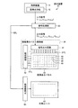
図1は、第1実施形態に係る表示装置の構成の一例を示すブロック図である。図2は、第1実施形態に係る画像表示パネルの概念図である。図1に示すように、第1実施形態の表示装置10は、信号処理部20と、画像表示パネル駆動部30と、画像表示パネル40と、光源駆動部50と、光源ユニット60とを有する。信号処理部20は、制御装置11の画像出力部12からの入力信号(RGBデータ)が入力され、入力信号に所定のデータ変換処理を加えて生成した信号を表示装置10の各部に送る。画像表示パネル駆動部30は、信号処理部20からの信号に基づいて画像表示パネル40の駆動を制御する。光源駆動部50は、信号処理部20からの信号に基づいて光源ユニット60の駆動を制御する。光源ユニット60は、光源駆動部50の信号に基づいて画像表示パネル40を背面から照明する。画像表示パネル40は、画像表示パネル駆動部30からの信号及び光源ユニット60からの光により画像を表示させる。
(First embodiment)
(Overall configuration of display device)
FIG. 1 is a block diagram illustrating an example of the configuration of the display device according to the first embodiment. FIG. 2 is a conceptual diagram of the image display panel according to the first embodiment. As illustrated in FIG. 1, the
(画像表示パネルの構成)
最初に、画像表示パネル40の構成について説明する。図1及び図2に示すように、画像表示パネル40は、画素48が、P0×Q0個(行方向にP0個、列方向にQ0個)、2次元のマトリクス状(行列状)に配列されている。図1に示す例は、XYの2次元座標系に複数の画素48がマトリクス状に配列されている例を示している。この例において、X方向は、水平方向(行方向)であり、Y方向は、垂直方向(列方向)であるが、これに限られず、X方向が垂直方向であってY方向が水平方向であってもよい。
(Image display panel configuration)
First, the configuration of the
画素48は、第1副画素49Rと、第2副画素49Gと、第3副画素49Bと、第4副画素49Wとを有する。第1副画素49Rは、第1色(例えば、赤色)を表示する。第2副画素49Gは、第2色(例えば、緑色)を表示する。第3副画素49Bは、第3色(例えば、青色)を表示する。第4副画素49Wは、第4色(例えば、白色)を表示する。第1色、第2色、第3色及び第4色は、赤色、緑色、青色及び白色に限られず、補色などでもよく、互いに色が異なっていればよい。第4色を表示する第4副画素49Wは、同じ光源点灯量で照射された場合、第1色を表示する第1副画素49R、第2色を表示する第2副画素49G、第3色を表示する第3副画素49Bよりも輝度が高いことが好ましい。以下において、第1副画素49Rと、第2副画素49Gと、第3副画素49Bと、第4副画素49Wとをそれぞれ区別する必要がない場合、副画素49という。また、副画素の配列する位置を区別して記載する場合、例えば画素48(p,q)の第4副画素を、第4副画素49W(p,q)と記載する。
The
画像表示パネル40は、カラー液晶表示パネルであり、第1副画素49Rと画像観察者との間に第1色を通過させる第1カラーフィルタが配置され、第2副画素49Gと画像観察者との間に第2色を通過させる第2カラーフィルタが配置され、第3副画素49Bと画像観察者との間に第3色を通過させる第3カラーフィルタが配置されている。また、画像表示パネル40は、第4副画素49Wと画像観察者との間にカラーフィルタが配置されていない。第4副画素49Wには、カラーフィルタの代わりに透明な樹脂層が備えられていてもよい。このように画像表示パネル40は、透明な樹脂層を設けることで、第4副画素49Wにカラーフィルタを設けないことにより生じる第4副画素49Wの大きな段差を抑制することができる。
The
(画像表示パネル駆動部の構成)
図1及び図2に示すように、画像表示パネル駆動部30は、信号出力回路31及び走査回路32を有する。画像表示パネル駆動部30は、信号出力回路31によって映像信号を保持し、順次、画像表示パネル40に出力する。より詳しくは、信号出力回路31は、信号処理部20からの出力信号に応じた所定の電位を有する画像出力信号を、画像表示パネル40に出力する。信号出力回路31は、信号線DTLによって画像表示パネル40と電気的に接続されている。走査回路32は、画像表示パネル40における副画素49の動作(光透過率)を制御するためのスイッチング素子(例えば、TFT)のON/OFFを制御する。走査回路32は、配線SCLによって画像表示パネル40と電気的に接続されている。
(Configuration of image display panel driver)
As shown in FIGS. 1 and 2, the image display
(光源駆動部及び光源部の構成)
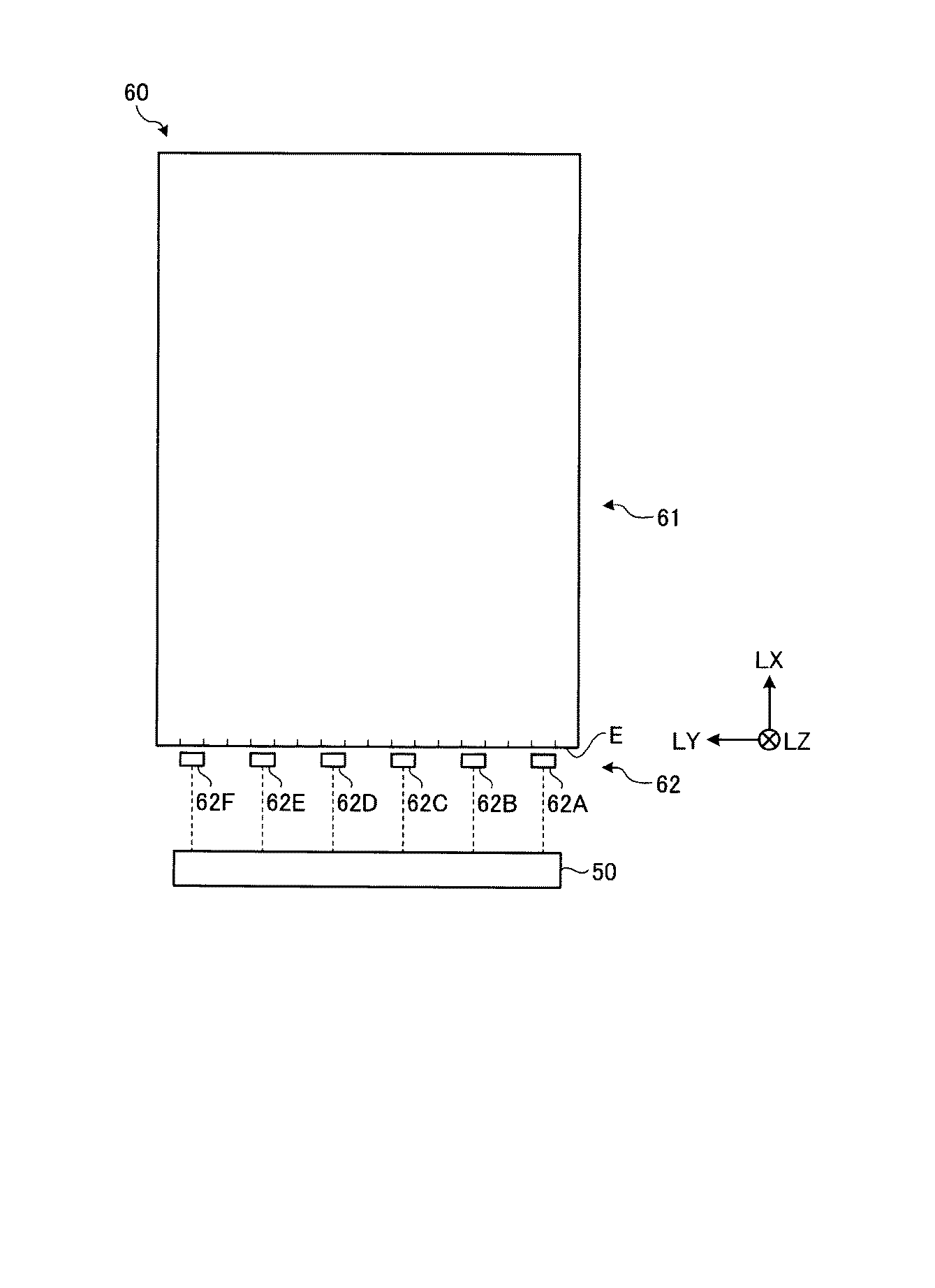
光源ユニット60(光源部)は、画像表示パネル40の背面に配置され、画像表示パネル40に向けて光を照射することで、画像表示パネル40を照明する。図3は、本実施形態に係る光源ユニットの説明図である。光源ユニット60は、導光板61と、導光板61の少なくとも一側面を入射面Eとして、この入射面Eに対向する位置に、複数の光源62A、62B、62C、62D、62E及び62Fを配列したサイドライト光源62と、を備えている。複数の光源62A、62B、62C、62D、62E及び62Fは、例えば、同色(例えば、白色)の発光ダイオード(LED:Light Emitting Diode)である。複数の光源62A、62B、62C、62D、62E及び62Fは、導光板61の一側面に沿って並んでおり、光源62A、62B、62C、62D、62E及び62Fが並ぶ光源配列方向をLYとした場合、光源配列方向LYに直交する入光方向LXに向けて、入射面Eから導光板61へ光源62A、62B、62C、62D、62E及び62Fの入射光が入光する。以下、光源62A、62B、62C、62D、62E及び62Fを区別しない場合は、光源62と記載する。
(Configuration of light source drive unit and light source unit)
The light source unit 60 (light source unit) is disposed on the back surface of the
光源駆動部50は、光源ユニット60が出力する光の光量等を制御する。具体的には、光源駆動部50は、信号処理部20から出力される面状光源装置制御信号SBLに基づいて光源ユニット60に供給する電流又はデューティ比(duty比)を調整することで、画像表示パネル40を照射する光の照射量(光の強度)を制御する。そして、光源駆動部50は、図3に示す複数の光源62A、62B、62C、62D、62E及び62Fに対して個々に独立して電流又はデューティ比(duty比)を制御し、各光源62A、62B、62C、62D、62E及び62Fの照射する光の光量(光の強度)を制御する、光源の分割駆動制御をすることができる。
The
導光板61は、光源配列方向LYに現れる両端面で光の反射が生じるため、光源配列方向LYに現れる両端面に近い、光源62A及び光源62Fが照射する光の強度分布と、光源62A及び光源62Fの間に配置される、例えば光源62Cが照射する光の強度分布が異なっている。このため、本実施形態に係る光源駆動部50は、図3に示す複数の光源62A、62B、62C、62D、62E及び62Fに対して個々に独立して電流又はデューティ比(duty比)を制御し、各光源62A、62B、62C、62D、62E及び62Fの光強度分布に応じて照射する光の光量(光の強度)を制御する必要がある。
Since the
光源ユニット60は、光源62A〜62Fの入射光が光源配列方向LYに直交する入光方向LXに向けて照射され、入射面Eから導光板61に入る。導光板61に入射した光は、拡散しながら入射方向LXに進む。導光板61は、光源62A〜62Fから照射され入射した光を画像表示パネル40を背面から照明する照明方向LZへ照射する。本実施形態において、照明方向LZは、光源配列方向LYと、入光方向LXとに直交する。
The
図4は、光源ユニットの射出面の領域を示す模式図である。本実施形態の表示装置10は、画像表示パネル40が画像を表示する面である画像表示面に向けて光源ユニット60が光を射出する面である射出面102を、仮想的に複数の領域104に分割している。領域104は、入光方向LXに平行な複数の分割線106と、光源配列方向LYに平行な複数の分割線108とで、マトリックス状に分割されている。分割線106は、光源62A〜62Fのうち、隣接する2つの光源の間に設けられている。したがって、分割線106は、等間隔に5本設けられている。これにより、領域104は、各光源62A〜62Fに対応した領域となる。また、分割線108が、等間隔で2本設けられている。これにより、射出面102は、3行6列の18個の領域104に分割されている。なお、領域104を分割する数は特に限定されないが、光源配列方向LYは、光源の配置に合わせて分割することが好ましい。これにより各光源の出力を制御しやすくなる。表示装置10は、領域104のうちの1つを対象領域として、対象領域毎に後述する領域光照射値1/αを算出する。対象領域は、領域104と、その領域104から光が照射される画像表示パネル40の画像表示面の領域と、を有する。画像表示面の領域は、画像表示パネル40の画像表示面全体の一部分の領域であって、領域内に画素48を有する。ただし、上述のように領域104の数は任意であるため、領域104は、1つであって射出面102の全体を占めるものであってもよく、それに対応する画像表示面の領域も、1つであって画像表示面の領域全体占めるものであってよい。
FIG. 4 is a schematic diagram showing an area of the emission surface of the light source unit. In the
(信号処理部の構成)
信号処理部20は、制御装置11から入力される入力信号を処理して出力信号を生成する。信号処理部20は、赤色(第1色)、緑色(第2色)、青色(第3色)の色を組み合わせて表示させる入力信号の入力値を、赤色(第1色)、緑色(第2色)、青色(第3色)及び白色(第4色)で再現される拡大色空間(第1実施形態ではHSV色空間)の再現値(出力信号)に変換して生成する。そして、信号処理部20は、生成した出力信号を画像表示パネル駆動部30に出力する。拡大色空間については後述する。なお、第1実施形態において、拡大色空間はHSV色空間であるが、これに限られずXYZ色空間、YUV空間その他の座標系でもよい。また、信号処理部20は、光源駆動部50に出力する光源制御信号SBLも生成する。
(Configuration of signal processor)
The
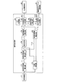
図5は、第1実施形態に係る信号処理部の構成の概要を示すブロック図である。図5に示すように、信号処理部20は、仮伸長係数算出部72、色相判定部73、画素指標値算出部74、塊判定部76、塊指標値算出部78、領域指標値算出部80、光照射量決定部82、伸長係数算出部84、及び出力信号生成部86を有する。信号処理部20のこれらの各部は、互いに独立したもの(回路等)でもよく、互いに共通するものであってもよい。
FIG. 5 is a block diagram showing an outline of the configuration of the signal processing unit according to the first embodiment. As shown in FIG. 5, the
仮伸長係数算出部72は、制御装置11から画像の入力信号を取得し、入力信号を伸長するための仮の係数である仮伸長係数α1を画素48毎に算出する。仮伸長係数算出部72は、画像表示パネル40中の全画素48について、仮伸長係数α1を算出する。仮伸長係数算出部72は、画素48毎に、入力信号に基づいて表示する色の彩度、及び明度を算出し、それらに基づき仮伸長係数α1を算出する。仮伸長係数算出部72による仮伸長係数α1の算出方法については、後述する。
Temporary extension coefficient calculation unit 72 obtains an input signal of the image from the control unit 11, a temporary extension coefficient alpha 1 which is the coefficient of the temporary for expanding the input signal is calculated for each
色相判定部73は、入力信号に基づいて、各画素の色相を判定する。 The hue determination unit 73 determines the hue of each pixel based on the input signal.
画素指標値算出部74は、仮伸長係数算出部72から各画素48の仮伸長係数α1の情報を取得する。画素指標値算出部74は、各画素48の仮伸長係数α1に基づき、画素48毎に画素指標値1/α1を算出する。画素指標値算出部74は、画像表示パネル40中の全画素48について、画素指標値1/α1を算出する。画素指標値1/α1は、光源ユニット60が照射する光の照射量を求めるための指標である。第1実施形態における画素指標値1/α1は、値が大きくなるほど光源ユニット60の光源点灯量が大きくなり(光の照射量の削減率が小さくなり)、値が小さくなるほど光源ユニット60の光源点灯量が小さくなる(光の照射量の削減率が大きくなる)。画素指標値1/α1は、値が1/α1である。すなわち、ある画素48の画素指標値1/α1の値は、その画素48における仮伸長係数α1の逆数となる。
The pixel index value calculation unit 74 acquires information on the temporary expansion coefficient α 1 of each
塊判定部76は、画素指標値算出部74から画素48の画素指標値1/α1の情報を取得し、色相判定部73から画素48の色相の情報を取得する。塊判定部76は、画素指標値1/α1及び色相の情報に基づき、全ての画素48のうちから選択された起点画素48sと、他の画素48とが連続するかを判定する連続判定を行い、連続する画素の領域を塊であると判定する。起点画素48sは、連続判定を行う場合の起点となる画素である。塊判定部76は、全ての画素48のうちから、画素指標値1/α1が予め決められた所定の値以上である画素を、起点画素48sとして選択する。ただし、塊判定部76は、所定の値を定めず、全ての画素48のうちから任意で起点画素48sを選択してもよい。塊判定部76は、連続判定において連続すると判定した画素の領域を塊と判定する。塊とは、連続判定において連続すると判定された複数の画素48からなる画素群であるということもできる。なお、塊判定部76は、色相判定部73の色相の情報については使用しても使用しなくてもよい。塊判定部76による連続判定方法の詳細は、後述する。
The chunk determination unit 76 acquires information on the
塊指標値算出部78は、塊判定部76が判定した塊中の各画素48の画素指標値1/α1の情報を取得する。塊指標値算出部78は、塊中の各画素48の画素指標値1/α1の情報に基づき、その塊の指標値である塊指標値1/α2を算出する。なお、塊指標値1/α2は、塊を構成する画素48における光源ユニット60の光の照射量を求めるための指標である。塊指標値算出部78による塊指標値1/α2の算出処理の詳細は、後述する。
The lump index value calculation unit 78 acquires information on the
領域指標値算出部80は、画素指標値算出部74から対象領域中の画素48における画素指標値1/α1の情報を取得し、色相判定部73から対象領域中の画素48の色相の情報を取得する。領域指標値算出部80は、画素指標値1/α1の情報と色相の情報とに基づき、対象領域における全域の指標値である領域指標値1/α3を算出する。領域指標値1/α3は、対象領域への光源ユニット60の光の照射量を求めるための指標であり、対象領域中の全画素48に共通する指標である。なお、領域指標値算出部80は、色相判定部73の色相の情報については使用しても使用しなくてもよい。領域指標値算出部80による領域指標値1/α3の算出処理の詳細は、後述する。
The area index value calculation unit 80 acquires information on the
光照射量決定部82は、塊指標値算出部78から塊指標値1/α2の情報を取得し、領域指標値算出部80から領域指標値1/α3の情報を取得する。光照射量決定部82は、対象領域における塊指標値1/α2の値と領域指標値1/α3の値とを比較し、光源ユニット60の光の照射量が大きくなる方の値に基づき、対象領域における光源ユニット60の光の照射量を決定する。具体的には、光照射量決定部82は、対象領域における塊指標値1/α2の値と領域指標値1/α3の値とのうち、光源ユニット60の光の照射量が大きくなる方の値を、領域光照射値1/αとする。なお、領域光照射値1/αは、光源ユニット60の光の照射量を示す値である。領域光照射値1/αは、値が大きくなるほど光源ユニット60の光源点灯量が大きくなり(光の照射量の削減率が小さくなり)、値が小さくなるほど光源ユニット60の光源点灯量が小さくなる(光の照射量の削減率が大きくなる)。
The light irradiation amount determination unit 82 acquires the information of the
LD記憶部83は、光源ユニット60の各光源62の輝度分布情報LDの情報を記憶する。上述のように、光源62は、それぞれ照射する光の強度分布(輝度分布)が異なっている。輝度分布情報LDは、その各光源62の輝度分布の情報である。光照射量決定部82は、領域光照射値1/αと、輝度分布情報LDとに基づき、光源ユニット60の各光源の点灯量である領域点灯量1/α’を決定する。光照射量決定部82は、領域点灯量1/α’の情報を、光源制御信号SBLとして、光源駆動部50に出力する。
The
また、光照射量決定部82は、領域点灯量1/α’に基づき、画素光照射量1/α0を算出する。画素光照射量1/α0は、各画素48に対して光源ユニット60が照射する光の照射量である。伸長係数算出部84は、光照射量決定部82から、画素光照射量1/α0の情報を取得する。伸長係数算出部84は、画素光照射量1/α0の値に基づき、対象領域中の画素48の入力信号を伸長するための伸長係数α0を算出する。
The light irradiation amount determining unit 82 calculates the pixel
出力信号生成部86は、伸長係数算出部84から伸長係数α0の情報を取得する。出力信号生成部86は、伸長係数α0の値及び入力信号に基づき、対象領域中の画素48に所定の色を表示させるための出力信号を生成する。出力信号生成部86は、生成した出力信号を、画像表示パネル駆動部30に出力する。出力信号生成部86による出力信号の生成処理は、後述する。
The output
(表示装置の処理動作)
(画素指標値の算出処理)
次に、表示装置10の処理動作のうち、画素指標値1/α1の算出処理について説明する。上述のように、画素指標値1/α1は、仮伸長係数α1に基づき算出される。図6は、本実施形態の表示装置で再現可能な再現HSV色空間の概念図である。図7は、再現HSV色空間の色相と彩度との関係を示す概念図である。
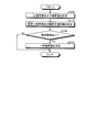
(Processing of display device)
(Pixel index value calculation processing)
Next, a calculation process of the
ここで、表示装置10は、画素48に第4色(白色)を出力する第4副画素49Wを備えることで、図6に示すように、再現される色空間(第1実施形態では、HSV色空間)における明度のダイナミックレンジが広げられている。つまり、図6に示すように、表示装置10が再現する拡大色空間は、第1副画素49R、第2副画素49G及び第3副画素49Bで表示できる円柱形状の色空間の上に、彩度が高くなるほど明度の最大値が低くなる、彩度軸と明度軸とを含む断面における形状が、斜辺が曲線となる略台形形状となる立体が載っている形状となる。第4色(白色)を加えることで拡大された拡大色空間(第1実施形態では、HSV色空間)における彩度Sを変数とした明度の最大値Vmax(S)が、信号処理部20に記憶されている。つまり、信号処理部20は、図6に示す拡大色空間の立体形状について、彩度と色相の座標(値)毎に明度の最大値Vmax(S)の値を記憶している。ここで、入力信号は、第1副画素49R、第2副画素49G及び第3副画素49Bの入力信号で構成されているため、入力信号の色空間は、円柱形状、つまり、拡大色空間の円柱形状部分と同じ形状となる。
Here, the
仮伸長係数α1は、入力信号を伸長して、出力信号により再現する色空間を拡大色空間に拡大するための仮の値である。信号処理部20は、仮伸長係数算出部72により、対象領域中の画素48における副画素49の入力信号値に基づき、これらの画素48における彩度S及び明度V(S)を求め、仮伸長係数α1を算出する。以下、具体的に説明する。
The temporary expansion coefficient α 1 is a temporary value for expanding the input signal and expanding the color space reproduced by the output signal to the expanded color space. Based on the input signal value of the sub-pixel 49 in the
ここで、彩度S及び明度V(S)は、S=(Max−Min)/Max及びV(S)=Maxで表される。彩度Sは0から1までの値をとることができ、明度V(S)は0から(2n−1)までの値をとることができ、nは表示階調ビット数である。また、Maxは、画素への第1副画素49Rの入力信号値、第2副画素49Gの入力信号値及び第3副画素49Bの入力信号値の3つの副画素の入力信号値の最大値である。Minは、画素への第1副画素49Rの入力信号値、第2副画素49Gの入力信号値及び第3副画素49Bの入力信号値の3つの副画素の入力信号値の最小値である。また、色相Hは、図7に示すように0°から360°で表される。0°から360°に向かって、赤(Red)、黄色(Yellow)、緑(Green)、シアン(Cyan)、青(Blue)、マゼンタ(Magenta)、赤となる。
Here, the saturation S and the lightness V (S) are represented by S = (Max−Min) / Max and V (S) = Max. The saturation S can take a value from 0 to 1, the lightness V (S) can take a value from 0 to (2 n −1), and n is the number of display gradation bits. In addition, Max is the maximum value of the input signal values of the three subpixels, that is, the input signal value of the
信号処理部20は、表示する画像の情報である入力信号が制御装置11から入力される。入力信号は、各画素に対して、その位置で表示する画像(色)の情報を入力信号として含んでいる。具体的には、第(p,q)番目の画素(但し、1≦p≦I,1≦q≦Q0)に対して、信号値がx1−(p,q)の第1副画素の入力信号、信号値がx2−(p,q)の第2副画素の入力信号、及び、信号値がx3−(p,q)の第3副画素の入力信号が含まれる信号が信号処理部20に入力される。
The
一般に、第(p,q)番目の画素において、円柱のHSV色空間における入力色の彩度(Saturation)S(p,q)、明度(Value)V(S)(p,q)は、第1副画素の入力信号(信号値x1−(p,q))、第2副画素の入力信号(信号値x2−(p,q))及び第3副画素の入力信号(信号値x3−(p,q))に基づき、次の式(1)及び式(2)より求めることができる。 In general, in the (p, q) -th pixel, the saturation (Saturation) S (p, q) and the lightness (Value) V (S) (p, q) of the input color in the cylindrical HSV color space are The input signal (signal value x 1- (p, q) ) of one subpixel, the input signal of the second subpixel (signal value x 2− (p, q) ), and the input signal (signal value x) of the third subpixel 3- (p, q) ) can be obtained from the following equations (1) and (2).
S(p,q)=(Max(p,q)−Min(p,q))/Max(p,q)・・・(1)
V(S)(p,q)=Max(p,q)・・・(2)
S (p, q) = (Max (p, q) −Min (p, q) ) / Max (p, q) (1)
V (S) (p, q) = Max (p, q) (2)
ここで、Max(p,q)は、(x1−(p,q)、x2−(p,q)、x3−(p,q))の3個の副画素49の入力信号値の最大値であり、Min(p,q)は、(x1−(p,q)、x2−(p,q)、x3−(p,q))の3個の副画素49の入力信号値の最小値である。第1実施形態ではn=8とした。すなわち、表示階調ビット数を8ビット(表示階調の値を0から255の256階調)とした。 Here, Max (p, q) is an input signal value of three sub-pixels 49 of (x 1-(p, q) , x 2-(p, q) , x 3-(p, q) ). Min (p, q) is the value of three sub-pixels 49 of (x 1-(p, q) , x 2-(p, q) , x 3-(p, q) ). This is the minimum value of the input signal value. In the first embodiment, n = 8. That is, the number of display gradation bits is 8 bits (the display gradation value is 256 gradations from 0 to 255).
信号処理部20は、仮伸長係数算出部72により、対象領域中の各画素48の明度V(S)(p,q)及び拡大色空間のVmax(S)に基づき、次の式(3)により仮伸長係数α1を算出する。仮伸長係数α1は、画素48毎に異なる値をとる場合がある。
Based on the brightness V (S) (p, q) of each
α1(p,q)=Vmax(S)/V(S)(p,q)・・・(3) α 1 (p, q) = Vmax (S) / V (S) (p, q) (3)
信号処理部20は、画素指標値算出部74により、α1(p,q)の逆数を算出し、算出したα1(p,q)の逆数を、第(p,q)番目の画素48の画素指標値1/α1(p,q)とする。信号処理部20は、このようにして、各画素48の画素指標値1/α1を算出する。
In the
(塊指標値の算出処理)
次に、塊判定部76による連続判定、及び塊指標値の算出処理について説明する。連続判定において、塊判定部76は、画像表示パネル40中の全ての画素48のうちから、連続判定を開始する起点となる起点画素48sを選択し、画像表示パネル40中の全ての画素48のうちから抽出したサンプリング点の画素48に対して、連続判定を行う。塊判定部76は、起点画素48sから判定方向Z側のサンプリング点の各画素48に対して、判定方向Zに沿って順番に連続判定を行う。ここで、判定方向Zは、水平方向(X方向)及び垂直方向(Y方向)であり、塊判定部76は、水平方向及び垂直方向のそれぞれの方向で連続判定を行う。ただし、塊判定部76は、水平方向と垂直方向のいずれかのみの方向で連続判定を行ってもよく、水平方向又は垂直方向から傾斜した方向を判定方向Zとして連続判定してもよい。なお、水平方向は、画像を画像表示パネル40に書き込む際の書き込み位置が移動する方向である。つまり、データの処理時に信号が処理される画素の移動方向が水平方向となる。垂直方向は、上述のように水平方向に直交する方向である。また、塊判定部76は、サンプリング点の画素について解析を行うことで、サンプリング点をとらずに全ての画素48を解析するよりも、演算処理を低減することができる。また、サンプリング点は、所定の画素間隔で設けることが好ましい。また、サンプリング点は、水平方向、垂直方向にずれていてもよいし、重なる位置でもよい。ただし、塊判定部76は、サンプリング点をとらずに、全ての画素48に対して連続判定を行ってもよい。
(Process of calculating lump index value)
Next, the continuous determination by the lump determination unit 76 and the calculation process of the lump index value will be described. In the continuous determination, the lump determination unit 76 selects a starting pixel 48 s as a starting point for starting the continuous determination from all the
具体的には、塊判定部76は、起点画素48sを選択したら、起点画素48sの画素指標値1/α1に基づき、連続判定のための連続判定値を算出する。第1実施形態においては、連続判定値は、上境界値Up及び下境界値Boである。上境界値Upは、起点画素48sの画素指標値1/α1より大きい値であり、下境界値Boは、起点画素48sの画素指標値1/α1より小さい値である。塊判定部76は、起点画素48sの画素指標値1/α1よりも所定値A1だけ大きい値を、上境界値Upとする。また、塊判定部76は、起点画素48sの画素指標値1/α1よりも所定値A2だけ小さい値を、下境界値Boとする。所定値A1、A2は、予め設定されている値であり、互いに同じ値である。ただし、所定値A1、A2は、それぞれ異なる値でもよく、例えば操作者の設定などにより変更可能であってもよい。
Specifically, the mass determination unit 76, upon selecting the origin pixel 48s, based on the
上境界値Up及び下境界値Boを算出した後、塊判定部76は、選択した起点画素48sから判定方向Zに沿ってサンプリング点の画素48に対して連続判定を行う。連続判定を行う画素を判定画素48uとすると、塊判定部76は、判定画素48uの画素指標値1/α1が、下境界値Boと上境界値Upとの間の値(下境界値Bo以上、上境界値Up以下の値)である場合に、判定画素48uは起点画素48sに連続する画素であると判定する。塊判定部76は、判定画素48uの画素指標値1/α1が、下境界値Boと上境界値Upとの間の値の範囲外の値である場合は、判定画素48uは起点画素48sに連続しない画素であると判定する。塊判定部76は、判定画素48uが連続すると判定した場合、次のサンプリング点の画素48を判定画素48uとして同様の連続判定を行う。塊判定部76は、起点画素48sから、連続していないと判定される画素48の直前に連続していると判定された画素48までの間の画素48を、連続する画素であると判定する。
After calculating the upper boundary value Up and the lower boundary value Bo, the lump determination unit 76 performs continuous determination on the
塊判定部76は、判定画素48uが連続しないと判定した場合、この連続判定を中断する。塊判定部76は、連続しないと判定された判定画素48uを、新たな起点画素48sとして選択し、この新たな起点画素48sを起点として、連続判定を再開する。1つの連続判定において連続すると判定された画素48は、互いに連続しているものであるが、異なる連続判定における画素48同士は、互いに連続しない。
When determining that the determination pixels 48u are not continuous, the lump determination unit 76 interrupts the continuous determination. The lump determination unit 76 selects the determination pixel 48u determined not to be continuous as a new start pixel 48s, and restarts the continuous determination using the new start pixel 48s as a start point. The
また、より詳しくは、塊判定部76は、判定画素48uの直前に連続判定した画素である直前画素48tがある場合、直前画素48tの画素指標値1/α1が下境界値Boと上境界値Upとの間の値であり、かつ、判定画素48uの画素指標値1/α1が下境界値Boと上境界値Upとの間の値である場合に、起点画素48sから判定画素48uまでが連続すると判定するということができる。すなわち、直前画素48tが下境界値Boと上境界値Upとの間の値でない場合、直前画素48tは連続していないと判定されるので、その次に判定される判定画素48uが下境界値Boと上境界値Upとの間の値であっても、判定画素48uが起点画素48sと連続しているとは判定されない。
Further, more specifically, the mass determination unit 76 determines the pixel if the immediately preceding 48u has previous pixel 48t is continuous the determined pixel, previous pixel
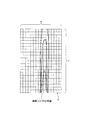
図8は、連続判定を説明するための一例を示す説明図である。以上説明した連続判定の一例を、図8により説明する。図8の横軸は、サンプリング点の各画素48を示し、縦軸はサンプリング点の各画素48の画素指標値1/α1を示す。すなわち、図8は、サンプリング点の画素48毎の画素指標値1/α1を示したものである。
FIG. 8 is an explanatory diagram illustrating an example for explaining the continuous determination. An example of the continuous determination described above will be described with reference to FIG. The horizontal axis of FIG. 8 indicates each
塊判定部76は、図8に示すように、画素48a1を起点画素48sとして選択して連続判定を行う場合、画素48a1の画素指標値1/α1に基づき、画素48a1の上境界値Upa1と、画素48a1の下境界値Boa1とを算出する。
Mass determination unit 76, as shown in FIG. 8, when performing continuity judgment by selecting pixels 48 a1 starting pixel 48s, based on the
上境界値Upa1と下境界値Boa1とを算出した後、塊判定部76は、画素48a1の判定方向Zに沿った次のサンプリング点の画素である画素48a2を判定画素48uとして、画素48a2が画素48a1と連続しているかを判定する。図8に示すように、画素48a2の画素指標値1/α1は、上境界値Upa1と下境界値Boa1と間の値である。従って、塊判定部76は、画素48a2が画素48a1と連続していると判定する。
After calculating an upper boundary value Up a1 and the lower boundary value Bo a1, mass determination unit 76, as a determination pixel 48u pixel 48 a2 is the next pixel sampling points along the determined direction Z of the pixel 48 a1, determining whether the pixel 48 a2 are continuous with the pixel 48 a1. As shown in FIG. 8, the
画素48a2が連続していると判定した後、塊判定部76は、画素48a2の次のサンプリング点の画素である画素48a3を判定画素48uとして、画素48a3が画素48a1と連続しているかを判定する。図8に示すように、画素48a3の画素指標値1/α1は、上境界値Upa1と下境界値Boa1と間の値である。従って、塊判定部76は、画素48a3が画素48a1と連続していると判定する。
After determining that the pixel 48 a2 are continuous, mass determination unit 76, as a determination pixel 48u pixel 48 a3 is a pixel of the next sampling point of the pixel 48 a2, pixel 48 a3 is continuous with the pixel 48 a1 Judge whether it is. As shown in FIG. 8, the
画素48a2が連続していると判定した後、塊判定部76は、同様に画素48a3の次のサンプリング点の画素である画素48a4の連続判定を行う。図8に示すように、画素48a4の画素指標値1/α1は、上境界値Upa1と下境界値Boa1と間の範囲外の値である。従って、塊判定部76は、画素48a4が画素48a1と連続していないと判定する。塊判定部76は、画素48a1から画素48a3までが連続していると判定し、画素48a1から画素48a3までの間にある複数の画素48を、塊と判定する。
After determining that the
塊判定部76は、画素48a4が画素48a1と連続していないと判定したため、画素48a1を起点画素48sとした連続判定を中断する。そして、塊判定部76は、画素48a4を起点画素48sとした連続判定を新たに再開する。塊判定部76は、同様に、画素48a4の上境界値Upa4と下境界値Boa4とを算出する。塊判定部76は、画素48a4の次のサンプリング点の画素である画素48a5の連続判定を行う。図8に示すように、画素48a5の画素指標値1/α1は、上境界値Upa4と下境界値Boa4と間の値である。従って、塊判定部76は、画素48a5が画素48a4と連続していると判定する。塊判定部76は、このように同様の連続判定処理を繰り返す。
Mass determination unit 76, since the pixel 48 a4 is determined not to be continuous with the pixel 48 a1, it interrupts the continuity judgment that the origin pixel 48s of the pixel 48 a1. The mass determination unit 76, newly resumes continuous determination that the origin pixel 48s of the pixel 48 a4. The lump determination unit 76 similarly calculates the upper boundary value Up a4 and the lower boundary value Bo a4 of the
塊判定部76は、以上説明したように連続判定を行い、連続していると判定した画素48同士を、塊であると判定する。塊指標値算出部78は、塊判定部76から、塊を構成する画素の情報(位置情報)と、その塊中の各画素48の画素指標値1/α1の情報とを取得する。塊指標値算出部78は、塊中の全画素48の画素指標値1/α1のうちの最大値を、その塊における塊指標値1/α2とする。塊指標値1/α2は、その塊に含まれる各画素48に共通する値である。なお、塊中の全画素48には、起点画素48sも含まれる。
The lump determination unit 76 performs continuous determination as described above, and determines the
以上説明した塊指標値1/α2の算出処理の処理フローを、フローチャートに基づき説明する。図9は、塊指標値の算出処理を説明するフローチャートである。図9に示すように、塊指標値算出部78は、塊判定部76の連続判定の結果に基づき、水平方向の塊指標値1/α2を算出しつつ(ステップS10)、垂直方向の塊指標値1/α2を算出する(ステップS12)。なお、ステップS10とステップS12の処理は、後述する。ここで、ステップS10の処理とステップS12の処理は並行して行ってもよいし、順番に行ってもよい。
A processing flow of the calculation processing of the
塊指標値算出部78は、水平方向、垂直方向の塊指標値1/α2を算出したら、水平方向の塊指標値1/α2>垂直方向の塊指標値1/α2であるかを判定する(ステップS14)。塊指標値算出部78は、水平方向の塊指標値1/α2>垂直方向の塊指標値1/α2である(ステップS14でYes)と判定した場合、水平方向の塊指標値1/α2を塊指標値1/α2に決定し(ステップS16)、本処理を終了する。塊指標値算出部78は、水平方向の塊指標値1/α2>垂直方向の塊指標値1/α2ではない(ステップS14でNo)、つまり水平方向の塊指標値1/α2≦垂直方向の塊指標値1/α2であると判定した場合、水平方向の塊指標値1/α2<垂直方向の塊指標値1/α2であるかを判定する(ステップS17)。
After calculating the
塊指標値算出部78は、水平方向の塊指標値1/α2<垂直方向の塊指標値1/α2である(ステップS17でYes)と判定した場合、垂直方向の塊指標値1/α2を塊指標値1/α2に決定し(ステップS18)、本処理を終了する。つまり、塊指標値算出部78は、水平方向と垂直方向のうち大きい方の塊指標値1/α2を塊指標値1/α2に設定する。塊指標値算出部78は、水平方向の塊の塊指標値1/α2<垂直方向の塊指標値1/α2ではない(ステップS17でNo)と判定した場合、つまり、水平方向の塊指標値1/α2=垂直方向の塊指標値1/α2である場合、色相の優先順位に基づいて塊指標値1/α2を決定する(ステップS19)。具体的には、水平方向の塊指標値1/α2と垂直方向の塊指標値1/α2とのうち、色相優先順位の高い方の塊指標値1/α2を塊指標値1/α2とする。優先順位としては、優先順位が高い順に、黄、黄緑、シアン、緑、マゼンタ、バイオレット、赤、青の順が例示される。
Mass index value calculating unit 78 is a horizontal
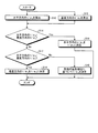
次に、水平方向の塊指標値1/α2の算出方法(決定方法)ついて説明する。図10は、水平方向の塊指標値の算出処理を説明するフローチャートである。信号処理部20は、塊判定部76により、判定方向Zを水平方向として連続判定を行い、連続判定の判定結果に基づき、水平方向の塊指標値1/α2を算出する。
Next, a calculation method (determination method) of the
図10に示すように、信号処理部20は、塊判定部76により、起点画素48sの画素指標値1/α1を抽出し(ステップS22)、起点画素48sの画素指標値1/α1≧閾値であるかを判定する(ステップS24)。ここで、閾値は、予め決められた所定の値であり、画素指標値1/α1として、塊検出の考慮が必要ない(本実施形態の調整が必要ない)範囲と判定するための基準である。閾値は、8‘h20が例示されるがこれに限定されない。塊判定部76は、起点画素48sの画素指標値1/α1≧閾値でない(ステップS24でNo)、すなわち画素指標値1/α1<閾値であると判定した場合、ステップS34に進む。
As illustrated in FIG. 10, the
塊判定部76は、起点画素48sの画素指標値1/α1>閾値以上である(ステップS24でYes)と判定した場合、連続判定のための連続判定値を決定する(ステップS25)。第1実施形態において、連続判定値は、起点画素48sの画素指標値1/α1に基づいて算出される上境界値Up及び下境界値Boである。
If it is determined that the
連続判定値を決定した後、塊判定部76は、起点画素48sの水平方向に隣接するサンプリング点の画素指標値1/α1を抽出して(ステップS26)、サンプリング点の画素が起点画素48sと連続しているかを判定する(ステップS28)。塊判定部76は、サンプリング点の画素の画素指標値1/α1が、連続判定値の範囲内の値(上境界値Up及び下境界値Boの間の値)である場合、サンプリング点の画素が起点画素48sと連続していると判定する。なお、塊判定部76は、例えば2以上の設定した数以上のサンプリング点の画素が起点画素48sと連続している場合に、連続していると判定してもよい。すなわち、この場合、塊判定部76は、起点画素48sとその次のサンプリング点の画素48である画素48kとが連続し、起点画素48sと画素48kの次のサンプリング点の画素48lが連続していない場合は、起点画素48sと画素48kとは連続していないと判定する。
After determining the continuity determination value, the lump determination unit 76 extracts the
塊判定部76は、画素が連続していない(ステップS28でNo)と判定した場合、サンプリングのフラグを保持し、連続検出信号をリセットし(ステップS30)、ステップS34に進む。連続検出信号は、サンプリング点が連続している間ONとなる信号である。塊判定部76は、画素が連続している(ステップS28でYes)と判定した場合、起点画素48s及びサンプリング点の画素48の画素指標値1/α1と、そのフラグとを保持し(ステップS32)、ステップS34に進む。
If it is determined that the pixels are not continuous (No in step S28), the lump determination unit 76 holds a sampling flag, resets the continuous detection signal (step S30), and proceeds to step S34. The continuous detection signal is a signal that is ON while sampling points are continuous. Mass determination unit 76, when judging that pixel is continuous (Yes in step S28), and the
塊判定部76は、サンプリング点の判定を行ったら、水平方向の領域の境界に到達しているかを判定する(ステップS34)。塊判定部76は、水平方向の領域の境界に到達していない(ステップS34でNo)と判定した場合、ステップS22に戻り、次のサンプリング点について、上述と同様の処理を行う。塊判定部76は、このように、水平方向の領域の境界に到達するまで処理を繰り返す。塊判定部76は、水平方向の領域の境界に到達している(ステップS34でYes)と判定した場合、画像の境界、つまり画像表示パネルの画素の端まで到達したかを判定する(ステップS36)。 After determining the sampling point, the lump determination unit 76 determines whether the boundary of the horizontal region has been reached (step S34). If it is determined that the boundary of the horizontal region has not been reached (No in step S34), the lump determination unit 76 returns to step S22 and performs the same processing as described above for the next sampling point. In this way, the chunk determination unit 76 repeats the process until the boundary of the horizontal region is reached. If it is determined that the boundary of the horizontal region has been reached (Yes in step S34), the lump determination unit 76 determines whether the boundary of the image, that is, the end of the pixel of the image display panel has been reached (step S36). ).
塊判定部76は、画像の境界に到達していない(ステップS36でNo)と判定した場合、画素指標値1/α1とフラグを持ち越し(ステップS38)、ステップS22に戻る。塊判定部76は、画像の境界に到達している(ステップS36でYes)と判定した場合、水平方向の連続判定処理を終了するか、つまり、画像の全面のサンプリング点について連続判定を行ったかを判定する(ステップS40)。
Mass determination unit 76 does not reach the boundary of the image (step S36 in No) and if it is determined,
塊判定部76は、水平方向の連続判定を終了していない(ステップS40でNo)と判定した場合、次のラインに移動し、連続検出信号とフラグをリセットし(ステップS42)、ステップS22に戻る。塊判定部76は、水平方向の連続判定を終了した(ステップS40でYes)と判定した場合、対象領域毎に水平方向の塊指標値1/α2を決定し(ステップS44)、本処理を終了する。塊判定部76は、連続すると判定された画素の画素指標値1/α1のうち、最大値を水平方向の塊指標値1/α2とする。
If it is determined that the horizontal determination has not ended (No in step S40), the lump determination unit 76 moves to the next line, resets the continuous detection signal and flag (step S42), and proceeds to step S22. Return. Mass determination unit 76 to complete the continuous determination of the horizontal direction when it is determined (in step S40 Yes) and determines the horizontal
次に、垂直方向の塊指標値1/α2の算出方法(決定方法)ついて説明する。図11は、垂直方向の塊指標値の算出処理を説明するフローチャートである。信号処理部20は、塊判定部76により、判定方向Zを垂直方向として連続判定を行い、連続判定の判定結果に基づき、垂直方向の塊指標値1/α2を算出する。
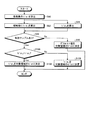
Next, a calculation method (determination method) of the
塊判定部76は、起点画素48sの画素指標値1/α1を抽出し(ステップS62)、起点画素48sの画素指標値1/α1≧閾値であるかを判定する(ステップS64)。塊判定部76は、起点画素48sの画素指標値1/α1≧閾値でない(ステップS64でNo)、すなわち画素指標値1/α1<閾値であると判定した場合、ステップS76に進む。
The chunk determination unit 76 extracts the
塊判定部76は、起点画素48sの画素指標値1/α1>閾値以上である(ステップS64でYes)と判定した場合、連続判定のための連続判定値を決定する(ステップS65)。第1実施形態において、連続判定値は、起点画素48sの画素指標値1/α1に基づいて算出される上境界値Up及び下境界値Boである。
If it is determined that the
連続判定値を決定した後、塊判定部76は、起点画素48sのフラグと画素指標値1/α1と連続判定値とをFIFO、RAM等に記憶し(ステップS66)、垂直方向に隣接するサンプリング点の画素指標値1/α1を抽出し(ステップS68)、サンプリング点の画素が連続しているかを判定する(ステップS70)。連続の判定方法は水平方向と同様である。
After determining the continuous determination value, mass determination unit 76 stores the flags and the pixel index value of the origin pixel 48s 1 /
塊判定部76は、サンプリング点の画素が連続していない(ステップS70でNo)と判定した場合、サンプリングのフラグを保持し、対象のサンプリング点に不連続の情報を対応付け(ステップS72)、ステップS76に進む。塊判定部76は、サンプリング点の画素が連続している(ステップS70でYes)と判定した場合、対象のサンプリング点に連続の情報を対応付け、サンプリング点の画素指標値1/α1を記憶し(ステップS74)、ステップS76に進む。
If it is determined that the sampling point pixels are not continuous (No in step S70), the lump determination unit 76 holds a sampling flag and associates discontinuous information with the target sampling point (step S72). Proceed to step S76. If it is determined that the sampling point pixels are continuous (Yes in step S70), the lump determination unit 76 associates continuous information with the target sampling point and stores the
塊判定部76は、サンプリング点の判定を行ったら、垂直方向の領域の境界に到達しているかを判定する(ステップS76)。塊判定部76は、垂直方向の領域の境界に到達していない(ステップS76でNo)と判定した場合、ステップS62に戻り、次のサンプリング点について、上述と同様の処理を行う。塊判定部76は、垂直方向の領域の境界に到達している(ステップS76でYes)と判定した場合、画像の境界、つまり画像表示パネル40の画素の端まで到達したかを判定する(ステップS80)。
After determining the sampling point, the lump determination unit 76 determines whether the boundary of the vertical region has been reached (step S76). If it is determined that the boundary of the vertical region has not been reached (No in step S76), the lump determination unit 76 returns to step S62 and performs the same processing as described above for the next sampling point. If it is determined that the boundary of the vertical region has been reached (Yes in step S76), the lump determination unit 76 determines whether the boundary of the image, that is, the end of the pixel of the
塊判定部76は、画像の境界に到達していない(ステップS80でNo)と判定した場合、ステップS62に戻る。塊判定部76は、画像の境界に到達している(ステップS80でYes)と判定した場合、垂直方向の連続判定を終了するか、つまり、画像の全面のサンプリング点について連続判定を行ったかを判定する(ステップS82)。 If the lump determination unit 76 determines that the boundary of the image has not been reached (No in step S80), the lump determination unit 76 returns to step S62. If it is determined that the boundary of the image has been reached (Yes in step S80), the lump determination unit 76 terminates the continuous determination in the vertical direction, that is, whether the continuous determination has been performed for sampling points on the entire surface of the image. Determination is made (step S82).
塊判定部76は、垂直方向の連続判定を終了していない(ステップS82でNo)と判定した場合、次のラインに移動し(ステップS84)、ステップS62に戻る。塊判定部76は、垂直方向の連続判定を終了した(ステップS82でYes)と判定した場合、対象領域毎に垂直方向の塊指標値1/α2を決定し(ステップS86)、本処理を終了する。塊判定部76は、連続すると判定された画素の画素指標値1/α1のうち、最大値を垂直方向の塊指標値1/α2とする。
If it is determined that the continuous determination in the vertical direction has not ended (No in step S82), the lump determination unit 76 moves to the next line (step S84) and returns to step S62. If it is determined that the continuous determination in the vertical direction has ended (Yes in step S82), the lump determination unit 76 determines the vertical
(領域指標値の算出処理)
次に、領域指標値算出部80による領域指標値1/α3の算出処理について説明する。
(Area index value calculation processing)
Next, the process of calculating the
領域指標値算出部80は、画素指標値算出部74から対象領域中の画素48における画素指標値1/α1の情報を取得し、色相判定部73から対象領域中の画素48の色相の情報を取得する。領域指標値算出部80は、所定のアルゴリズムを用いて、画素指標値1/α1の情報と色相の情報とに基づき、対象領域における全域の指標値である領域指標値1/α3を算出する。ここで、所定のアルゴリズムとしては、例えば、対象領域中の各画素48の画素指標値1/α1の分布を算出し、その値以上の画素指標値1/α1を有する画素が所定画素数以上となり、かつ最も値が大きい画素指標値1/α1を、領域指標値1/α3とする処理を用いることができる。領域指標値1/α3は、対象領域中の全画素48に共通する値である。領域指標値算出部80は、対象領域が複数ある場合は、全ての対象領域において、領域指標値1/α3を算出する。
The area index value calculation unit 80 acquires information on the
(領域光照射値の算出処理)
次に、光照射量決定部82による領域指標値1/α3の算出処理について説明する。
(Area light irradiation value calculation processing)
Next, the process of calculating the
光照射量決定部82は、塊指標値算出部78から塊指標値1/α2の情報を取得し、領域指標値算出部80から領域指標値1/α3の情報を取得する。光照射量決定部82は、対象領域における塊指標値1/α2の値と領域指標値1/α3の値とを比較し、対象領域における塊指標値1/α2の値と領域指標値1/α3の値とのうち、光源ユニット60の光の照射量が大きくなる方の値を、領域光照射値1/αとする。領域光照射値1/αは、対象領域中の全画素48に共通する値である。光照射量決定部82は、対象領域が複数ある場合は、全ての対象領域において、領域光照射値1/αを算出する。
The light irradiation amount determination unit 82 acquires the information of the
以下に、以上説明した領域光照射値1/αの算出処理フローを、フローチャートに基づいて説明する。図12は、領域光照射値の算出処理を示すフローチャートである。信号処理部20は、画素指標値算出部74により、各画素の画素指標値1/α1を算出し(ステップS90)、算出した各画素の画素指標値1/α1に基づいて、領域指標値算出部80により対象領域毎に領域指標値1/α3を決定しつつ(ステップS92)、塊指標値算出部78により塊指標値1/α2を算出する(ステップS94)。ここで、ステップS92の処理とステップS94の処理は並行して行ってもよいし、順番に行ってもよい。
Below, the calculation process flow of the area | region
信号処理部20は、塊指標値1/α2と領域指標値1/α3を決定したら、有効サンプルがあるかを判定する(ステップS96)。具体的には、解析した結果、有効と判定できるサンプルの数、サンプリング数が0より大きいかを判定する。信号処理部20は、有効サンプルがない(ステップS96でNo)、つまり有効サンプリング数が0であると判定した場合、光照射量決定部82により、予め設定されたデフォルト値を領域光照射値1/αに決定し(ステップS98)、本処理を終了する。ここで、デフォルト値としては、例えば8‘h20を用いることができる。なお、有効サンプルとは、サンプリング点の画素のうち連続すると判定された画素群、すなわち塊であり、有効サンプルがないとは、連続すると判定された画素がない、すなわち塊が検出されなかった場合をいう。
After determining the
信号処理部20は、有効サンプルがある(ステップS96でYes)、つまり有効サンプリング数が1以上であると判定した場合、領域指標値1/α3>塊指標値1/α2であるかを判定する(ステップS100)。信号処理部20は、領域指標値1/α3>塊指標値1/α2である(ステップS100でYes)と判定した場合、光照射量決定部82により、領域指標値1/α3を領域光照射値1/αに決定し(ステップS102)、本処理を終了する。信号処理部20は、領域指標値1/α3≦塊指標値1/α2である(ステップS100でNo)と判定した場合、光照射量決定部82により、塊指標値1/α2を領域光照射値1/αに決定し(ステップS104)、本処理を終了する。つまり、信号処理部20は、大きい方の値を領域光照射値1/αに設定する。
If the
(領域点灯量の決定処理)
次に、領域点灯量LAの決定処理について説明する。LD記憶部83は、光源62の輝度分布情報LDを記憶する。図3、4に示したように、複数の光源62は、それぞれ輝度分布(光の強度分布)が異なるので、それぞれの光源62について、光源62を所定の点灯量で点灯したときに検出される光源ユニット60の全面の輝度値を輝度分布情報LDとして記憶する。輝度分布情報について図13、14を用いて説明する。
(Area lighting amount determination process)
Next, the process for determining the area lighting amount LA will be described. The
図13は、輝度分布情報を説明するための模式図である。図13に示したように、輝度分布情報LDは、画像表示パネル40の画像表示面(または光源ユニット60の射出面102)をm×n(m、nは、1≦m≦P0、1≦n≦Q0を満たす任意の整数)の複数の領域104に分割し、領域104ごとに検出される光源ユニット60の輝度値(光の強度の値)を記憶するものである。領域104の数は、画素数を最大として任意に設定される。領域104が1画素に対応する場合には、輝度分布情報LDには画素単位の輝度値が記憶される。領域104が複数の画素に対応する場合には、領域104内の所定の位置にある画素を代表画素とし、代表画素における光源ユニット60の輝度値が記憶される。図13の例では、輝度値L1を示す輝度(L1)の分布線の内側の領域104の代表画素の輝度値には輝度値L1が設定される。LD記憶部83には、光源62ごとに、m×n個の領域104の輝度値をテーブル形式で設定した輝度分布情報LDが記憶される。以下の説明では、このテーブル形式の輝度分布情報LDを光源別ルックアップテーブルLUT(LUT;LookUp Table)と呼ぶ。光源別ルックアップテーブルLUTは、表示装置10に固有の情報であるので、事前に作成し、LD記憶部83に記憶しておく。
FIG. 13 is a schematic diagram for explaining the luminance distribution information. As shown in FIG. 13, the luminance distribution information LD is mxn (m and n are 1 ≦ m ≦ P 0 , 1 It is divided into a plurality of regions 104 (any integer satisfying ≦ n ≦ Q 0 ), and the luminance value (light intensity value) of the
図14は、光源別ルックアップテーブルを示した図である。光源別ルックアップテーブルLUTは、光源62A、62B、62C、62D、62E、62F、62G、62H、62I及び62Jそれぞれについて用意する。光源別ルックアップテーブルLUTAは、光源56Aを1灯だけ点灯したときの輝度値がm×n領域分テーブル形式で記録されたものである。同様に、光源56Bから光源56Jについて、同様の光源別ルックアップテーブルLUTが設定される。図14では、光源56Iについての光源別ルックアップテーブルLUT241I、光源56JについてのLUTJを示している。所定の領域104を代表する代表画素の輝度値によって構成すれば、光源ルックアップテーブルLUTのサイズを小さくし、LD記憶部83の記憶用容量を低減することができる。画素ごとの輝度値が必要なときは、補間演算を行って算出することができる。なお、光源別ルックアップテーブルLUTは、光源62を1灯ずつ点灯したときの情報であるが、例えば、光源56A、56Bの組、光源56C、56Dの組というように、それぞれを同時点灯した場合の光源別ルックアップテーブルを作成し、記憶しておくとしてもよい。これにより、光源別ルックアップテーブルLUTの作成作業を省力化できるとともに、LD記憶部83の記憶容量を低減できる。
FIG. 14 shows a lookup table for each light source. The light source lookup table LUT is prepared for each of the
また、光源別ルックアップテーブルLUTには、輝度値が輝度ムラ補正に対応するように補正された状態で設定されていてもよい。このような光源別ルックアップテーブルLUTを用いることにより、輝度ムラ補正も点灯パターンの決定と同時に行うことが可能となる。 Further, the light source lookup table LUT may be set in a state where the luminance value is corrected so as to correspond to the luminance unevenness correction. By using such a light source-specific lookup table LUT, luminance unevenness correction can be performed simultaneously with the determination of the lighting pattern.
光照射量決定部82は、領域光照射値1/αと、LD記憶部83に記憶される光源別ルックアップテーブルLUTに基づき、各光源62の点灯量(点灯パターン)である領域点灯量1/α’を決定する。領域点灯量1/α’は、演算により求めてもよい。また、仮領域点灯量を設定し、光源別ルックアップテーブルLUTを用いて仮領域点灯量における駆動時輝度分布情報を算出し、領域光照射値1/αと比較して補正し、領域点灯量1/α’を決定してもよい。光照射量決定部82は、領域点灯量1/α’に基づいて光源制御信号SBLを生成し、光源駆動部60へ出力する。
The light irradiation amount determining unit 82 is based on the region
輝度情報演算部26は、領域点灯量1/α’と、LD記憶部83に記憶される光源別ルックアップテーブルLUTとを用いて、領域点灯量1/α’によって各光源62を点灯したときの光源ユニット60の輝度値(光の照射量)である画素光照射量1/α0を画素ごとに演算する。まず、領域点灯量1/α’で光源62を点灯したときの光源別の駆動時輝度分布情報LDを、光源別ルックアップテーブルLUTを用いて算出する。光源別ルックアップテーブルLUTから画素単位の情報が得られないときは、補間演算を行って光源別の駆動時輝度分布情報LDを算出する。そして、光源別の駆動時輝度分布情報LDを合成し、光源62の駆動時輝度分布情報LDを求める。算出したサイドライト光源62の駆動時輝度分布情報LDには、画素光照射量1/α0が画素単位に設定されている。
The luminance information calculation unit 26 uses the
(出力信号の生成処理)
次に、出力信号の生成処理について説明する。最初に、信号処理部20は、伸長係数算出部84により、画素光照射量1/α0の値に基づき、伸長係数α0を算出する。伸長係数α0は、画素光照射量1/α0の逆数である。伸長係数α0は、画素毎に設定される値である。
(Output signal generation processing)
Next, output signal generation processing will be described. First, the
信号処理部20は、出力信号生成部86により、第1副画素49Rの表示階調を決定するための第1副画素の出力信号(信号値X1−(p,q))、第2副画素49Gの表示階調を決定するための第2副画素の出力信号(信号値X2−(p,q))、第3副画素49Bの表示階調を決定するための第3副画素の出力信号(信号値X3−(p,q))、及び第4副画素49Wの表示階調を決定するための第4副画素の出力信号(信号値X4−(p,q))を生成し、画像表示パネル駆動部30に出力する。以下、信号処理部20による出力信号の生成処理について、具体的に説明する。
The
伸長係数α0を算出した後、信号処理部20は、出力信号生成部86により、第4副画素の出力信号値X4−(p,q)を、少なくとも第1副画素の入力信号(信号値x1−(p,q))、第2副画素の入力信号(信号値x2−(p,q))及び第3副画素の入力信号(信号値x3−(p,q))に基づいて算出する。より詳しくは、信号処理部20は、出力信号生成部86により、Min(p,q)と伸長係数α0との積に基づき第4副画素の出力信号値X4−(p,q)を求める。具体的には、信号処理部20は、下記の式(4)に基づいて信号値X4−(p,q)を求めることができる。式(4)では、Min(p,q)と伸長係数α0との積をχで除しているが、これに限定するものではない。
After calculating the expansion coefficient α 0 , the
X4−(p,q)=Min(p,q)・α0/χ・・・(4) X 4− (p, q) = Min (p, q) · α 0 / χ (4)
ここで、χは表示装置10に依存した定数である。白色を表示する第4副画素49Wには、カラーフィルタが配置されていない。第4色を表示する第4副画素49Wは、同じ光源点灯量で照射された場合、第1色を表示する第1副画素49R、第2色を表示する第2副画素49G、第3色を表示する第3副画素49Bよりも明るい。第1副画素49Rに第1副画素49Rの出力信号の最大信号値に相当する値を有する信号が入力され、第2副画素49Gに第2副画素49Gの出力信号の最大信号値に相当する値を有する信号が入力され、第3副画素49Bに第3副画素49Bの出力信号の最大信号値に相当する値を有する信号が入力されたときの、画素48又は画素48の群が備える第1副画素49R、第2副画素49G及び第3副画素49Bの集合体の輝度をBN1−3とする。また、画素48又は画素48の群が備える第4副画素49Wに、第4副画素49Wの出力信号の最大信号値に相当する値を有する信号が入力されたときの第4副画素49Wの輝度をBN4としたときを想定する。すなわち、第1副画素49R、第2副画素49G及び第3副画素49Bの集合体によって最大輝度の白色が表示され、この白色の輝度がBN1−3で表される。すると、χを表示装置10に依存した定数としたとき、定数χは、χ=BN4/BN1−3で表される。
Here, χ is a constant depending on the
具体的には、第1副画素49R、第2副画素49G及び第3副画素49Bの集合体に、次の表示階調の値を有する入力信号として、信号値x1−(p,q)=255、信号値x2−(p,q)=255、信号値x3−(p,q)=255が入力されたときにおける白色の輝度BN1−3に対して、第4副画素49Wに表示階調の値255を有する入力信号が入力されたと仮定したときの輝度BN4は、例えば、1.5倍である。すなわち、第1実施形態にあっては、χ=1.5である。
Specifically, a signal value x 1− (p, q) is input to an aggregate of the
次に、信号処理部20は、出力信号生成部86により、少なくとも第1副画素の入力信号(信号値x1−(p,q))及び伸長係数α0に基づいて、第1副画素の出力信号(信号値X1−(p,q))を算出し、少なくとも第2副画素の入力信号(信号値x2−(p,q))及び伸長係数α0に基づいて第2副画素の出力信号(信号値X2−(p,q))を算出し、少なくとも第3副画素の入力信号(信号値x3−(p,q))及び伸長係数α0に基づいて第3副画素の出力信号(信号値X3−(p,q))を算出する。
Next, the
具体的には、信号処理部20は、第1副画素の入力信号、伸長係数α0及び第4副画素の出力信号に基づいて第1副画素の出力信号を算出し、第2副画素の入力信号、伸長係数α0及び第4副画素の出力信号に基づいて第2副画素の出力信号を算出し、第3副画素の入力信号、伸長係数α0及び第4副画素の出力信号に基づいて第3副画素の出力信号を算出する。
Specifically, the
つまり、信号処理部20は、χを表示装置10に依存した定数としたとき、第(p,q)番目の画素48(あるいは、第1副画素49R、第2副画素49G及び第3副画素49Bの組)への第1副画素の出力信号値X1−(p,q)、第2副画素の出力信号値X2−(p,q)及び第3副画素の出力信号値X3−(p,q)を、以下の式(5),(6),(7)から求める。
That is, the
X1−(p,q)=α0・x1−(p,q)−χ・X4−(p,q)・・・(5)
X2−(p,q)=α0・x2−(p,q)−χ・X4−(p,q)・・・(6)
X3−(p,q)=α0・x3−(p,q)−χ・X4−(p,q)・・・(7)
X 1- (p, q) = α 0 · x 1- (p, q) -χ · X 4- (p, q) ··· (5)
X 2- (p, q) = α 0 · x 2- (p, q) -χ · X 4- (p, q) ··· (6)
X 3- (p, q) = α 0 · x 3- (p, q) -χ · X 4- (p, q) ··· (7)
このように、信号処理部20は、各副画素49の出力信号を生成する。次に、第(p,q)番目の画素48における出力信号である信号値X1−(p,q)、X2−(p,q)、X3−(p,q)、X4−(p,q)の求め方(伸張処理)のまとめを説明する。次の処理は、(第1副画素49R+第4副画素49W)によって表示される第1原色の輝度、(第2副画素49G+第4副画素49W)によって表示される第2原色の輝度、(第3副画素49B+第4副画素49W)によって表示される第3原色の輝度の比を保つように行われる。しかも、色調を保持(維持)するように行われる。さらには、階調−輝度特性(ガンマ特性、γ特性)を保持(維持)するように行われる。また、いずれかの画素48又は画素48の群において、入力信号値のすべてが0である場合又は小さい場合、このような画素48又は画素48の群を含めることなく、伸長係数α0を求めればよい。
As described above, the
(第1工程)
まず、信号処理部20は、伸長係数算出部84により、対象領域における画素光照射量1/α0から、画素毎に伸長係数α0を算出する。
(First step)
First, the
(第2工程)
次に、信号処理部20は、第(p,q)番目の画素48における信号値X4−(p,q)を、少なくとも、信号値x1−(p,q)、信号値x2−(p,q)及び信号値x3−(p,q)に基づいて求める。第1実施形態にあっては、信号処理部20は、信号値X4−(p,q)を、Min(p,q)、伸長係数α0及び定数χに基づいて決定する。より具体的には、信号処理部20は、上述したとおり、信号値X4−(p,q)を、上記の式(4)に基づいて求める。信号処理部20は、対象領域の全画素48において信号値X4−(p,q)を求める。
(Second step)
Next, the
(第3工程)
その後、信号処理部20は、第(p,q)番目の画素48における信号値X1−(p,q)を、信号値x1−(p,q)、伸長係数α0及び信号値X4−(p,q)に基づき求め、第(p,q)番目の画素48における信号値X2−(p,q)を、信号値x2−(p,q)、伸長係数α0及び信号値X4−(p,q)に基づき求め、第(p,q)番目の画素48における信号値X3−(p,q)を、信号値x3−(p,q)、伸長係数α0及び信号値X4−(p,q)に基づき求める。具体的には、信号処理部20は、第(p,q)番目の画素48における信号値X1−(p,q)、信号値X2−(p,q)及び信号値X3−(p,q)を、上記の式(5)から(7)に基づいて求める。
(Third step)
Thereafter, the
信号処理部20は、出力信号生成部86により、以上の工程で対象領域毎に出力信号を生成し、生成した出力信号を、画像表示パネル駆動部30に出力する。
The
以上説明したように、表示装置10は、信号処理部20が、入力信号に基づき画素指標値1/α1を画素毎に算出する画素指標値算出部74と、上境界値Upと下境界値Boとの間の値を画素指標値1/α1とする画素が、起点画素48sから連続して存在するかを判定する連続判定を行い、連続する画素の領域を塊と判定する塊判定部76と、塊中の各画素48の画素指標値1/α1に基づき、塊指標値1/α2を算出する塊指標値算出部78と、対象領域の全域の画素48の画素指標値1/α1に基づき、領域指標値1/α3を算出する領域指標値算出部80と、塊指標値1/α2と領域指標値1/α3とを比較し、光の照射量が大きくなる方の値に基づき、対象領域における光源部の光の照射量(領域光照射値1/α)を決定する光照射量決定部82と、を有する。
As described above, in the
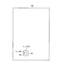
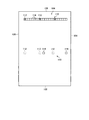
図15及び図16は、表示装置に表示される画素の光の照射量の一例を説明するための説明図である。表示装置10は、以上のように、光源ユニット60からの光の照射量を示す領域光照射値1/αを算出する際に、所定のアルゴリズムを用いて算出した領域指標値1/α3に加え、塊検出を行って算出した塊指標値1/α2を用いることで、画質の劣化が生じることを抑制することができる。つまり、図15に示す領域170ように、所定のアルゴリズムで電力の低減量を少なくして、画質を維持する場合はそのままとし、図16に示す領域180のように、所定のアルゴリズムでは、電力の低減量を大きくし、画質が劣化してしまう場合に塊検出で電力の低減量を少なくして、画質を維持することができる。図15に示す画像の場合、所定のアルゴリズムによって分散しているが所定個数以上ある画素172に対応して領域指標値1/α3を算出し、塊指標値算出部78によって画素の集合体である画素174(塊)に対応して塊指標値1/α2を算出する。このとき算出される領域光照射値1/αは、領域指標値1/α3の方が高い値となるため、領域指標値1/α3が領域170の領域光照射値1/αとなる。図16に示す画像の場合、所定のアルゴリズムによって所定個数以上ある画素186に対応して領域指標値1/α3を算出し、塊指標値算出部78によって画素の集合体である画素184(塊)に対応して塊指標値1/α2を算出する。このとき算出される領域光照射値1/αは、塊指標値1/α2の方が高い値となるため、塊指標値1/α2が領域180の領域光照射値1/αとなる。これにより、図16に示すように画素数としては少ないが、画素指標値1/α1が高くなる画素が集合している場合を塊判定部76で好適に検出することができ、画質の劣化を抑制しつつ、消費電力を低減することができる。また、画素の連続性で判定することで、簡単な処理で塊を検出することができる。
15 and 16 are explanatory diagrams for explaining an example of the light irradiation amount of the pixels displayed on the display device. As described above, when calculating the area
また、表示装置10は、画素指標値1/α1が、起点画素48sの画素指標値1/α1の値から所定の範囲内(上境界値Upと下境界値Boとの間)にある画素48を、連続する画素であると判断する。すなわち、表示装置10は、連続するか否かを決定する境界値を、起点画素48sの画素指標値1/α1に基づいて決定する。例えば連続するか否かを決定する境界値が起点画素48sの画素指標値1/α1によらず予め決められている場合、起点画素48sに近い画素指標値1/α1を有する画素であっても、境界値の範囲外であれば、連続しないと判定される。しかし、表示装置10は、起点画素48sの画素指標値1/α1に基づいて境界値を決定するため、値が近い画素指標値1/α1を有する画素について、適切に連続すると判定することできる。従って、表示装置10は、塊検出をより適切に行うことが可能となり、画質の劣化を抑制しつつ、消費電力を低減することができる。
Further, the
また、塊判定部76は、連続判定を、起点画素48sから判定方向Z側の各画素に対して、判定方向Zに沿って順番に行い、判定画素48uの直前に連続判定された画素である直前画素48tの画素指標値1/α1が上境界値Upと下境界値Boとの間の値であり、かつ、判定画素48uの画素指標値1/α1が上境界値Upと下境界値Boとの間の値である場合に、判定画素48uは起点画素48sから連続すると判定する。塊判定部76は、起点画素48sから判定画素48uまでの全てのサンプリング点の画素48が連続すると判定されていた場合に、判定画素48uが連続すると判定する。従って、表示装置10は、より適切に連続判定を行うことできる。
In addition, the lump determination unit 76 performs continuous determination for each pixel on the determination direction Z side from the start pixel 48s in order along the determination direction Z, and is a pixel that is continuously determined immediately before the determination pixel 48u. The
また、塊判定部76は、連続判定において、画素が連続しないと判断した場合に連続判定を中断し、連続しないと判定された画素を新たな起点画素として、連続判定を再開する。塊判定部76は、連続判定が途切れた後に、また新たに連続判定を再開するため、例えば画面中に輝度が異なる画素群が複数ある場合にも、適切にそれらを塊として検出することができる。従って、表示装置10は、塊検出をより適切に行うことが可能となる。
In addition, the lump determination unit 76 stops the continuous determination when it is determined that the pixels are not continuous in the continuous determination, and restarts the continuous determination using the pixel determined to be not continuous as a new starting pixel. Since the chunk determination unit 76 restarts the continuous judgment again after the continuation judgment is interrupted, for example, even when there are a plurality of pixel groups having different luminances on the screen, the chunk judgment unit 76 can appropriately detect them as a chunk. . Therefore, the
また、塊指標値算出部78は、塊中の各画素の画素指標値1/α1のうちの最大値を、塊指標値1/α2とする。塊指標値算出部78は、塊指標値1/α2の値を大きくすることができるため、より適切に画質の劣化を抑制しつつ、消費電力を低減することができる。
The lump index value calculation unit 78 sets the maximum value among the pixel index values 1 / α 1 of each pixel in the lump as the
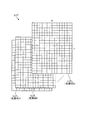
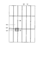
また、塊判定部76は、水平方向に沿って塊判定を行う。図17から図19は、水平方向の塊判定を行った場合を説明した説明図である。塊判定部76は、図10に示した水平方向の処理を行うことで、図17に示すように画素指標値1/α1が高い画素114が水平方向に連続している領域116を塊と判定することができる。具体的には、領域116にあるサンプリング点112の画素指標値1/α1を連続していると判定し、塊であると判定する。なお、画素指標値1/α1が高い画素114とは、彩度が高い画像、例えば、黄色、緑、赤等の原色、またはRGB、3色のうち2色の成分の階調が高く残りの1成分が0に近い画素である。また、塊判定部76は、図10に示した水平方向の処理を行うことで、図17に示すように画素指標値1/α1が高い画素114が水平方向に連続していない領域119に塊がないと判定する。
In addition, the lump determination unit 76 performs lump determination along the horizontal direction. FIG. 17 to FIG. 19 are explanatory diagrams illustrating the case where the horizontal block determination is performed. The chunk determination unit 76 performs the horizontal processing shown in FIG. 10, so that the
図18は、画素指標値1/α1が高い画素114が集合した塊122が範囲120で囲まれた複数の領域104にまたがっている場合を示している。また、図19は、範囲120を拡大して示している。塊判定部76は、図10に示した水平方向の処理を行い、水平方向の境界に到達したのちも画素指標値1/α1とフラグを持ち越すことで、図18及び図19に示すように塊122が隣接する領域104から延在している場合でも、実線124で示すように、分割線106を超えて、塊の判定結果を水平方向に持ち越すことで、隣接する領域104での塊を確実に検出することができる。
FIG. 18 shows a case where a
また、塊判定部76は、垂直方向に沿って塊判定を行う。図20は、垂直方向の塊判定を行った場合を説明した説明図である。塊判定部76は、図11に示した垂直方向の処理を行うことで、図20に示すように画素指標値1/α1が高い画素114が垂直方向に連続している領域150、152、154の塊を塊と判定することができる。また、塊判定部76は、図11に示した処理を行うことで、画素指標値1/α1が高い画素114が垂直方向に連続していない領域156、158、158に塊がないと判定する。
In addition, the lump determination unit 76 performs lump determination along the vertical direction. FIG. 20 is an explanatory diagram for explaining a case where the vertical block determination is performed. The chunk determination unit 76 performs the processing in the vertical direction illustrated in FIG. 11, so that the
(第2実施形態)
次に、第2実施形態について説明する。第2実施形態に係る表示装置10Aは、連続判定の判定方法が第1実施形態とは異なる。第2実施形態において第1実施形態と共通する箇所の説明は省略する。
(Second Embodiment)
Next, a second embodiment will be described. The display device 10A according to the second embodiment differs from the first embodiment in the determination method for continuous determination. In the second embodiment, descriptions of parts common to the first embodiment are omitted.
第2実施形態に係る表示装置10Aが有する塊判定部76は、連続判定のための連続判定値が、第1実施形態に係る塊判定部76とは異なる。第1実施形態における連続判定値は、上境界値Up及び下境界値Boであったが、第2実施形態における連続判定値は、上境界値Up及び下境界値Boに加え、一時境界値Te、限界上境界値Lup、限界下境界値Lboを含む。 The lump determination unit 76 included in the display device 10A according to the second embodiment is different from the lump determination unit 76 according to the first embodiment in the continuous determination value for continuous determination. The continuous determination values in the first embodiment are the upper boundary value Up and the lower boundary value Bo. However, the continuous determination values in the second embodiment are the temporary boundary value Te in addition to the upper boundary value Up and the lower boundary value Bo. , Upper boundary value L up , lower boundary value L bo .
塊判定部76は、第1実施形態と同じ方法で、起点画素48sの画素指標値1/α1から、上境界値Up及び下境界値Boを算出する。また、塊判定部76は、判定画素48uの直前に連続判定を行った直前画素48tがある場合、直前画素48tの画素指標値1/α1に基づき、一時境界値Teを算出する。一時境界値Teは、上境界値Upと下境界値Boとの間の範囲外の値であり、直前画素48tの画素指標値1/α1から所定値A3だけ値が異なる値である。所定値A3は、予め設定された値であり、上境界値Up及び下境界値Boと起点画素48sの画素指標値1/α1との差である所定値A1、A2と同じ値であるが、これに限られず異なる値であってもよく、例えば操作者の設定などにより変更可能であってもよい。
The lump determination unit 76 calculates the upper boundary value Up and the lower boundary value Bo from the
塊判定部76は、直前画素48tの画素指標値1/α1が起点画素48sの画素指標値1/α1より大きい場合は、一時境界値Teを上境界値Upより大きい値とし、直前画素48tの画素指標値1/α1が起点画素48sの画素指標値1/α1より小さい場合は、一時境界値Teを下境界値Boより小さい値とする。
Mass determination unit 76, when the pixel index values 1 / alpha 1 of the immediately preceding pixel 48t is larger than the
塊判定部76は、判定画素48tの画素指標値1/α1が、上境界値Upと下境界値Boとの間の値でなくても、直前画素48tの画素指標値1/α1と一時境界値Teとの間の値であれば、判定画素48tは起点画素48sに連続する画素であると判定する。より詳しくは、一時境界値Teが上境界値Upより大きい値である場合(直前画素48tの画素指標値1/α1が起点画素48sの画素指標値1/α1よりも大きい)、塊判定部76は、判定画素48tの画素指標値1/α1が、下境界値Boと一時境界値Teとの間の値(下境界値Bo以上、一時境界値Te以下)であれば、判定画素48tは起点画素48sに連続する画素であると判定する。また、一時境界値Teが下境界値Boより大きい値である場合(直前画素48tの画素指標値1/α1が起点画素48sの画素指標値1/α1よりも小さい)、塊判定部76は、判定画素48tの画素指標値1/α1が、上境界値Upと一時境界値Teとの間の値(一時境界値Te以上、上境界値Up以下)であれば、判定画素48tは起点画素48sに連続する画素であると判定する。
The lump determination unit 76 determines that the
このように、一時境界値Teは、直前画素48tの画素指標値1/α1に基づき、直前画素48tの次に連続判定される画素48だけに適用される拡大された境界値である。この一時境界値Teは、直前画素48tの画素指標値1/α1に基づき算出されるため、サンプリング点毎に異なる値となる場合がある。
Thus, the temporary boundary value Te, based on the
さらに、塊判定部76は、起点画素48sの画素指標値1/α1から、限界上境界値Lup、限界下境界値Lboを算出する。限界上境界値Lupは、上境界値Upより大きい値であり、限界下境界値Lboは、下境界値Boより小さい値である。塊判定部76は、上境界値Upよりも所定値A4だけ大きい値を、限界上境界値Lupとする。塊判定部76は、下境界値Boよりも所定値A5だけ小さい値を、限界下境界値Lboとする。所定値A4、A5は、予め設定された値であり、所定値A1、A2と同じ値であるが、これに限られず異なる値であってもよく、例えば操作者の設定などにより変更可能であってもよい。
Further, the lump determination unit 76 calculates the upper limit boundary value L up and the lower limit boundary value L bo from the
塊判定部76は、判定画素48tの画素指標値1/α1が、直前画素48tの画素指標値1/α1と一時境界値Teとの間の値であっても、限界上境界値Lupと限界下境界値Lboとの間(限界下境界値Lbo以上、限界上境界値Lup以下)の範囲外の値である場合、判定画素48tは起点画素48sに連続しないと判定する。すなわち、塊判定部76は、一時境界値Teにより連続判定の範囲を拡大しつつ、拡大した連続判定の上限値と下限値を、限界上境界値Lupと限界下境界値Lboに制限する。
Mass determination unit 76, the
図21は、第2実施形態における連続判定を説明するための一例を示す説明図である。以上説明した第2実施形態における連続判定の一例を、図21により説明する。図21の横軸は、サンプリング点の各画素48を示し、縦軸はサンプリング点の各画素48の画素指標値1/α1を示す。すなわち、図21は、図8と同様に、サンプリング点の画素48毎の画素指標値1/α1を示したものである。
FIG. 21 is an explanatory diagram illustrating an example for describing continuous determination in the second embodiment. An example of continuous determination in the second embodiment described above will be described with reference to FIG. The horizontal axis of FIG. 21 indicates each
塊判定部76は、図21に示すように、画素48a1を起点画素48sとして選択して連続判定を行う場合、画素48a1の画素指標値1/α1に基づき、画素48a1の上境界値Upa1及び下境界値Boa1と、限界上境界値Lupa1及び限界下境界値Lboa1とを算出する。
Mass determination unit 76, as shown in FIG. 21, when performing continuity judgment by selecting pixels 48 a1 starting pixel 48s, based on the
塊判定部76は、画素48a1の判定方向Zに沿って、各サンプリング点の画素が画素48a1と連続しているかを判定する。画素48a2、48a3は、画素指標値1/α1が画素48a1の上境界値Upa1と下境界値Boa1との間の値であるため、画素48a1と連続する。
Mass determination unit 76, along a determined direction Z of the
一方、画素48a4は、画素指標値1/α1が上境界値Upa1よりも大きい。ただし、画素48a4の画素指標値1/α1は、直前画素である画素48a3の画素指標値1/α1に基づき算出された一時境界値Tea4以下の値であり、かつ、限界上境界値Lupa1以下の値である。従って、画素48a4は、上境界値Upa1と下境界値Boa1との間の値ではないが、画素48a3の画素指標値1/α1と一時境界値Tea4との間の値であるため、画素48a1と連続すると判定される。
On the other hand, the
また、画素48a5は、画素指標値1/α1が上境界値Upa1よりも大きく、直前画素である画素48a4の画素指標値1/α1に基づき算出された一時境界値Tea5以下の値である。ただし、画素48a5は、画素指標値1/α1が限界上境界値Lupa1よりも大きい。すなわち、画素48a5は、画素48a4の画素指標値1/α1と一時境界値Tea5との間の値であるが、限界上境界値Lupa1及び限界下境界値Lboa1との間の値でないため、画素48a1と連続しないと判定される。なお、画素指標値1/α1が限界上境界値Lupa1及び限界下境界値Lboa1との間の値であっても、直前画素48の画素指標値1/α1と一時境界値Teとの間の値でない場合も、その画素は連続しないと判定される。
Further, the
塊判定部76は、画素48a1から画素48a4が連続すると判定し、画素48a5は連続しないと判定して、連続判定を中断する。塊判定部76は、画素48a5を新たな起点画素48sとして、連続判定を再開する。 Mass determination unit 76 determines that the pixel 48 a4 are continuous from the pixel 48 a1, pixel 48 a5 is determined not continuously interrupts the continuity judgment. Mass determination unit 76, the pixel 48 a5 as the new origin pixel 48s, resumes continuous determination.
以上説明した第2実施形態における連続判定処理を、フローチャートにより説明する。最初に、連続判定値の算出方法について説明する。図22は、第2実施形態における連続判定値の算出方法を説明するフローチャートである。図22は、図10のステップS25、及び図11のステップS65における連続判定値の算出において、第2実施形態の算出方法を詳細に説明したフローチャートである。図22に示すように、塊判定部76は、連続判定値の算出において、起点画素48sの画素指標値1/α1に基づき、上境界値Up及び下境界値Boを決定(算出)し(ステップS110)、起点画素48sの画素指標値1/α1に基づき、限界上境界値Lupと限界下境界値Lboとを決定(算出)する(ステップS112)。ステップS112は、ステップS110と同時に行われてもよい。
The continuous determination process in 2nd Embodiment demonstrated above is demonstrated with a flowchart. First, a method for calculating the continuous determination value will be described. FIG. 22 is a flowchart illustrating a method for calculating a continuous determination value in the second embodiment. FIG. 22 is a flowchart illustrating in detail the calculation method of the second embodiment in the calculation of the continuous determination value in step S25 of FIG. 10 and step S65 of FIG. As illustrated in FIG. 22, the lump determination unit 76 determines (calculates) the upper boundary value Up and the lower boundary value Bo based on the
限界上境界値Lupと限界下境界値Lboとを算出した後、塊判定部76は、連続判定を行う画素に、直前に連続判定された直前画素48tがあるかを判断する(ステップS114)。塊判定部76は、直前画素48tがあると判断した場合(ステップS114でYes)、直前画素48tの画素指標値1/α1に基づき、一時境界値Teを決定(算出)し(ステップS116)、連続判定値の算出処理は終了する。塊判定部76は、直前画素48tがないと判断した場合(ステップS114でNo)も、連続判定値の算出処理を終了する。なお、ステップS114は、直前画素48tがあると判断した場合にのみ行ってもよい。
After calculating the upper limit boundary value L up and the lower limit boundary value L bo , the lump determination unit 76 determines whether there is the immediately preceding pixel 48 t that has been determined to be continuous immediately before the pixels that are subjected to continuous determination (step S 114). ). When determining that there is the immediately previous pixel 48t (Yes in Step S114), the lump determination unit 76 determines (calculates) the temporary boundary value Te based on the
次に、連続判定の方法について説明する。図23は、第2実施形態における連続判定値の算出方法を説明するフローチャートである。図23は、図10のステップS28、及び図11のステップS70における連続判定方法において、第2実施形態の連続判定方法を詳細に説明したフローチャートである。図23に示すように、塊判定部76は、下境界値Bo≦サンプリング点の画素指標値1/α1≦上境界値Upであるかを判定する(ステップS120)。塊判定部76は、下境界値Bo≦サンプリング点の画素指標値1/α1≦上境界値Upである場合(ステップS120でYes)、サンプリング点の画素が連続していると判断し(ステップS122)、この処理を終了する。
Next, a method for continuous determination will be described. FIG. 23 is a flowchart illustrating a method for calculating a continuous determination value in the second embodiment. FIG. 23 is a flowchart illustrating in detail the continuous determination method of the second embodiment in the continuous determination method in step S28 of FIG. 10 and step S70 of FIG. As shown in FIG. 23, the lump determination unit 76 determines whether or not the lower boundary value Bo ≦ the
また、塊判定部76は、下境界値Bo≦サンプリング点の画素指標値1/α1≦上境界値Upでないと判断した場合(ステップS120でNo)、限界下境界値Lbo≦サンプリング点の画素指標値1/α1≦限界上境界値Lupであるかを判定する(ステップS124)。塊判定部76は、限界下境界値Lbo≦サンプリング点の画素指標値1/α1≦限界上境界値Lupでない場合(ステップS124でNo)、サンプリング点の画素が連続していないと判断し(ステップS126)、この処理を終了する。
In addition, when the lump determination unit 76 determines that the lower boundary value Bo ≦ the
塊判定部76は、限界下境界値Lbo≦サンプリング点の画素指標値1/α1≦限界上境界値Lupである場合(ステップS124でYes)、サンプリング点の画素指標値1/α1が、一時境界値Teと直前画素48tの画素指標値1/α1の間の値であるかを判定する(ステップS128)。塊判定部76は、サンプリング点の画素指標値1/α1が、一時境界値Teと直前画素48tの画素指標値1/α1の間の値である場合(ステップS128でYes)、サンプリング点の画素が連続していると判断し(ステップS122)、この処理を終了する。塊判定部76は、サンプリング点の画素指標値1/α1が、一時境界値Teと直前画素48tの画素指標値1/α1の間の値でない場合(ステップS128でNo)、サンプリング点の画素が連続していないと判断し(ステップS126)、この処理を終了する。
If the lower boundary value L bo ≦ the sampling point
以上のように、第2実施形態に係る表示装置10Aの塊判定部76は、判定画素48uの画素指標値1/α1が、直前画素48tの画素指標値1/α1と、一時境界値Teとの間の値である場合には、判定画素48uは起点画素48sから連続すると判定する。塊判定部76は、判定画素48uの画素指標値1/α1が、上境界値Upと下境界値Boとの間の値でない場合であっても、一時境界値Teの範囲内の値である場合は、判定画素48uが連続すると判定する。塊判定部76は、画素指標値1/α1が起点画素48sから離れた値であっても、直前に連続判定された直前画素48tの画素指標値1/α1に近い値であれば、連続すると判定する。従って、塊判定部76は、より適切に塊検出を行うことができる。
As described above, the mass determination unit 76 of the display device 10A according to the second embodiment, the
また、一時境界値Teは、直前画素48tの画素指標値1/α1が起点画素48sの画素指標値1/α1より大きい場合に、上境界値Upより大きい値となり、直前画素48tの画素指標値1/α1が起点画素48sの画素指標値1/α1より小さい場合に、下境界値Boより小さい値となる。塊判定部76は、一時境界値Teにより、連続すると判定される画素指標値1/α1の値の範囲を、適切に増加させることができるため、より適切に塊検出を行うことができる。
The temporary boundary value Te is larger than the upper boundary value Up when the
また、塊判定部76は、判定画素48uの画素指標値1/α1が、直前画素48tの画素指標値1/α1と一時境界値Teとの間の値であっても、限界下境界値Lboと限界上境界値Lupとの間の範囲外の値である場合には、判定画素48uは起点画素48sから連続しないと判定する。塊判定部76は、連続すると判定される画素指標値1/α1の値の範囲を、一時境界値Teによって広げつつ、限界下境界値Lboと限界上境界値Lupとを限界とする。塊判定部76は、連続すると判定される画素指標値1/α1の値の範囲を適切な範囲まで広げることができるため、より適切に塊検出を行うことができる。
Further, the mass determination unit 76, the
(第3実施形態)
次に、第3実施形態について説明する。第3実施形態に係る表示装置10Bは、塊指標値1/α2の算出方法が第1実施形態とは異なる。第3実施形態において第1実施形態と共通する箇所の説明は省略する。
(Third embodiment)
Next, a third embodiment will be described. Display device 10B according to the third embodiment, a method of calculating the
第3実施形態に係る表示装置10Bが有する塊指標値算出部78Bは、塊中の全画素48の画素指標値1/α1の内の最大値と最小値との間の値を、その塊の塊指標値1/α2とする。より詳しくは、塊指標値算出部78Bは、塊中の全画素48の画素指標値1/α1の平均に基づき、その塊の塊指標値1/α2を算出する。具体的には、塊指標値算出部78Bは、次の式(8)に示すように、塊中の全画素48の画素指標値1/α1の加算平均値を、その塊の塊指標値1/α2とする。
Mass index value calculating section 78B of the display device 10B according to the third embodiment, a value between the maximum value and the minimum value of the pixel index values 1 / alpha 1 of all the
![]()
![]()
式(8)におけるnは、塊中に含まれる画素48の数、すなわち起点画素48sを含む連続すると判定された画素の数である。また、式(8)における1/α1akは、起点画素48sを含む塊中のいずれかの画素48の画素指標値1/α1である。
In Expression (8), n is the number of
塊指標値算出部78Bは、このように塊中の全画素48の画素指標値1/α1の加算平均値を、その塊の塊指標値1/α2とするが、これに限られず、例えば加算平均値に所定の係数を加えたり乗じたりしてもよく、他の平均処理を用いて算出するものであってもよい。
Mass index value calculating section 78B, thus the average value of the pixel index values 1 / alpha 1 of all the
また、塊指標値算出部78Bは、塊中の全画素48の画素指標値1/α1の内の最大値と最小値との間の値を、その塊の塊指標値1/α2とするものであればよく、例えば、判定画素48uの画素指標値1/α1と起点画素48sの画素指標値1/α1との差分同士を平均して算出した差分平均値と、起点画素の画素指標値1/α1とに基づき、塊指標値1/α2を算出してもよい。ここで、差分平均値は、判定画素48uの画素指標値1/α1と起点画素48sの画素指標値1/α1との差分値を、塊中の各画素48毎に算出し、その差分値同士を平均した値である。塊指標値算出部78Bは、例えば、起点画素の画素指標値1/α1に、この差分平均値を加えることにより、塊指標値1/α2を算出する。具体的には、塊指標値算出部78Bは、例えば次の式(9)に基づき、塊指標値1/α2を算出する。
Moreover, mass index value calculation unit 78B has a value between the maximum value and the minimum value of the pixel index values 1 / alpha 1 of all the
![]()
![]()
ただし、式(9)における1/α1a0は、起点画素48sの画素指標値1/α1であり、式(9)における1/α1akは、起点画素48sを含まない塊中のいずれかの画素48の画素指標値1/α1である。また、式(9)におけるmは、次の式(10)に示す値である。
However, 1 / α 1a0 in equation (9) is the
ここで、式(10)におけるNは、次の式(11)に示す値である。 Here, N in the equation (10) is a value shown in the following equation (11).
![]()
![]()
ここで、式(11)におけるCeiling(x)という関数は、値がxを越えない最大の整数を算出する天井関数である。すなわち、式(11)におけるNは、nの平方根を越えない最大の整数である。 Here, the function called Ceiling (x) in Equation (11) is a ceiling function that calculates the maximum integer whose value does not exceed x. That is, N in Equation (11) is the largest integer that does not exceed the square root of n.
以上のように、塊指標値算出部78Bは、式(9)に基づき塊の塊指標値1/α2を算出する場合、mを2の階乗毎の値とする。従って、塊指標値算出部78Bは、式(9)に基づき塊の塊指標値1/α2を算出する場合、演算の容量を抑制することができる。また、塊指標値算出部78Bは、連続する画素48の数が所定数以上である場合(nが所定の値以上である場合)、その所定数の数までの画素48について式(9)により塊指標値1/α2を算出し、それをその塊の塊指標値1/α2としてもよい。この場合、所定数は、例えば63であるが、これに限られない。この場合においても、塊指標値算出部78Bは、演算数が多くなることを抑制するため、演算の容量を抑制することができる。さらに、所定数までは演算を行っているため、演算精度の低下も抑制することができる。なお、塊指標値算出部78Bは、差分平均値と起点画素の画素指標値1/α1とに基づき、塊指標値1/α2を算出するものであれば、塊指標値1/α2の算出方法は、上述の式(9)に限られない。
As described above, when the lump index value calculation unit 78B calculates the
以上説明したように、塊指標値算出部78Bは、塊中の全画素48の画素指標値1/α1の内の最大値と最小値との間の値を、その塊の塊指標値1/α2とする。塊指標値算出部78Bは、塊中の全画素48の画素指標値1/α1の値に基づき塊の塊指標値1/α2を算出するため、より適切に画質の劣化を抑制しつつ、消費電力を低減することができる。
As described above, the mass index value calculation section 78B, a value between the maximum value and the minimum value of the pixel index values 1 / alpha 1 of all the
また、塊指標値算出部78Bは、塊中の各画素48の画素指標値1/α1の平均に基づき、塊指標値1/α2を算出する。この塊指標値算出部78Bは、塊中の全画素48の画素指標値1/α1の平均に基づき塊の塊指標値1/α2を算出するため、より適切に画質の劣化を抑制しつつ、消費電力を低減することができる。
Moreover, mass index value calculation section 78B, based on the average of the pixel index values 1 / alpha 1 for each
また、塊指標値算出部78Bは、塊中の画素48の画素指標値1/α1と起点画素48sの画素指標値1/α1との差分同士を平均して算出した差分平均値と、起点画素48sの画素指標値1/α1と、に基づき、塊指標値1/α2を算出してもよい。塊指標値算出部78Bは、差分平均値に基づき塊の塊指標値1/α2を算出するため、より適切に画質の劣化を抑制しつつ、消費電力を低減することができる。
Moreover, mass index value calculation unit 78B includes a difference average value difference between the calculated average of the
(適用例)
次に、図24及び図25を参照して、第1実施形態で説明した表示装置10の適用例について説明する。図24及び図25は、第1実施形態に係る表示装置を適用する電子機器の一例を示す図である。第1実施形態に係る表示装置10は、図24に示すカーナビゲーションシステム、テレビジョン装置、デジタルカメラ、ノート型パーソナルコンピュータ、図25に示す携帯電話等の携帯端末装置あるいはビデオカメラなどのあらゆる分野の電子機器に適用することが可能である。言い換えると、第1実施形態に係る表示装置10は、外部から入力された映像信号あるいは内部で生成した映像信号を、画像あるいは映像として表示するあらゆる分野の電子機器に適用することが可能である。電子機器は、表示装置に映像信号を供給し、表示装置の動作を制御する制御装置11(図1参照)を備える。なお、本適用例は、第1実施形態に係る表示装置10以外でも、以上説明した他の実施形態に係る表示装置にも適用できる。
(Application example)
Next, an application example of the
図24に示す電子機器は、第1実施形態に係る表示装置10が適用されるカーナビゲーション装置である。表示装置10は、自動車の車内のダッシュボード300に設置される。具体的にはダッシュボード300の運転席311と助手席312の間に設置される。カーナビゲーション装置の表示装置10は、ナビゲーション表示、音楽操作画面の表示、又は、映画再生表示等に利用される。
The electronic apparatus shown in FIG. 24 is a car navigation device to which the
図25に示す電子機器は、第1実施形態に係る表示装置10が適用される携帯型コンピュータ、多機能な携帯電話、音声通話可能な携帯コンピュータまたは通信可能な携帯コンピュータとして動作し、いわゆるスマートフォン、タブレット端末と呼ばれることもある、情報携帯端末である。この情報携帯端末は、例えば筐体562の表面に表示部561を有している。この表示部561は、第1実施形態に係る表示装置10と外部近接物体を検出可能なタッチ検出(いわゆるタッチパネル)機能とを備えている。
The electronic device shown in FIG. 25 operates as a portable computer to which the
以上、本発明の実施形態を説明したが、これらの実施形態の内容によりこれらの実施形態が限定されるものではない。また、前述した構成要素には、当業者が容易に想定できるもの、実質的に同一のもの、いわゆる均等の範囲のものが含まれる。さらに、前述した構成要素は適宜組み合わせることが可能である。さらに、前述した実施形態の要旨を逸脱しない範囲で構成要素の種々の省略、置換又は変更を行うことができる。 As mentioned above, although embodiment of this invention was described, these embodiment is not limited by the content of these embodiment. In addition, the above-described constituent elements include those that can be easily assumed by those skilled in the art, those that are substantially the same, and those in a so-called equivalent range. Furthermore, the above-described components can be appropriately combined. Furthermore, various omissions, substitutions, or changes of the components can be made without departing from the spirit of the above-described embodiment.
10 表示装置
20 信号処理部
30 画像表示パネル駆動部
40 画像表示パネル
48 画素
48s 起点画素
48t 直前画素
48u 判定画素
49R 第1副画素
49G 第2副画素
49B 第3副画素
49W 第4副画素
50 光源駆動部
60 光源ユニット
72 仮伸長係数算出部
74 画素指標値算出部
76 塊判定部
78 塊指標値算出部
80 領域指標値算出部
82 光照射量決定部
84 伸長係数算出部
86 出力信号生成部
DESCRIPTION OF
Claims (13)
前記画像表示パネルに光を照射する光源部と、
画像の入力信号に基づいて前記画素を制御し、かつ、前記光源部の光の照射量を制御する信号処理部と、を備え、
前記信号処理部は、
前記入力信号に基づき、前記光源部から照射される光の照射量を求めるための指標である画素指標値を前記画素毎に算出する画素指標値算出部と、
起点画素の前記画素指標値より大きい値である上境界値と、前記起点画素の前記画素指標値より小さい値である下境界値との間の値を前記画素指標値とする画素が、前記起点画素から連続して存在するかを判定する連続判定を行い、連続する画素の領域を塊と判定する塊判定部と、
前記塊中の各画素の前記画素指標値に基づき、前記塊の指標値である塊指標値を算出する塊指標値算出部と
対象領域の全域の画素の前記画素指標値に基づき、前記対象領域の全域の指標値である領域指標値を算出する領域指標値算出部と、
前記塊指標値と前記領域指標値とを比較し、光の照射量が大きくなる方の値に基づき、前記対象領域における前記光源部の光の照射量を決定する光照射量決定部と、
を有する、表示装置。 An image display panel in which a plurality of pixels are arranged in a matrix;
A light source unit for irradiating the image display panel with light;
A signal processing unit that controls the pixel based on an input signal of the image and controls the amount of light emitted from the light source unit,
The signal processing unit
A pixel index value calculation unit that calculates, for each pixel, a pixel index value that is an index for obtaining an irradiation amount of light emitted from the light source unit based on the input signal;
A pixel having a value between the upper boundary value that is larger than the pixel index value of the starting pixel and the lower boundary value that is smaller than the pixel index value of the starting pixel as the pixel index value, A block determination unit that performs continuous determination to determine whether or not there is a continuous pixel, and determines a continuous pixel region as a block;
Based on the pixel index value of each pixel in the chunk, a chunk index value calculation unit that calculates a chunk index value that is the index value of the chunk, and the target region based on the pixel index value of pixels in the entire target region An area index value calculation unit for calculating an area index value that is an index value of the entire area of
A light irradiation amount determination unit that compares the lump index value and the region index value and determines a light irradiation amount of the light source unit in the target region based on a value that increases a light irradiation amount;
A display device.
前記画像表示パネルに光を照射する光源部と、を備える表示装置の駆動方法であって、
画像の入力信号を検出する入力信号検出ステップと、
前記入力信号に基づき、前記光源部から照射される光の照射量を求めるための指標である画素指標値を前記画素毎に算出する画素指標値算出ステップと、
起点画素の画素指標値より大きい値である上境界値と、前記起点画素の画素指標値より小さい値である下境界値との間の値を画素指標値とする画素が、前記起点画素から連続して存在するかを判定する連続判定を行い、連続する画素の領域を塊と判定する塊判定ステップと、
前記塊中の各画素の画素指標値に基づき、前記塊の指標値である塊指標値を算出する塊指標値算出ステップと、
対象領域の全域の画素の前記画素指標値に基づき、前記対象領域の全域の指標値である領域指標値を算出する領域指標値算出ステップと、
前記塊指標値と前記領域指標値とを比較し、光の照射量が大きくなる方の値に基づき、前記対象領域における前記光源部の光の照射量を決定する光照射量決定ステップと、
前記決定した光の照射量に基づいて前記光源部の光の照射量を制御する制御ステップと、を有する表示装置の駆動方法。 An image display panel in which a plurality of pixels are arranged in a matrix;
A light source unit for irradiating the image display panel with light, and a display device driving method comprising:
An input signal detection step for detecting an input signal of the image;
A pixel index value calculating step for calculating, for each pixel, a pixel index value that is an index for obtaining an irradiation amount of light emitted from the light source unit based on the input signal;
A pixel having a pixel index value that is a value between an upper boundary value that is larger than the pixel index value of the starting pixel and a lower boundary value that is smaller than the pixel index value of the starting pixel is continuous from the starting pixel A continuous determination for determining whether or not a block is present, and a block determination step of determining a continuous pixel region as a block;
A block index value calculating step for calculating a block index value that is an index value of the block based on a pixel index value of each pixel in the block;
An area index value calculating step for calculating an area index value that is an index value of the entire area of the target area based on the pixel index value of the pixels of the entire area of the target area;
A light irradiation amount determining step for comparing the mass index value and the region index value, and determining a light irradiation amount of the light source unit in the target region, based on a value that increases a light irradiation amount,
And a control step of controlling the light irradiation amount of the light source unit based on the determined light irradiation amount.
Priority Applications (2)
| Application Number | Priority Date | Filing Date | Title |
|---|---|---|---|
| JP2015081611A JP2016200745A (en) | 2015-04-13 | 2015-04-13 | Display device, electronic instrument and display device drive method |
| US15/084,523 US9898973B2 (en) | 2015-04-13 | 2016-03-30 | Display device, electronic apparatus and method of driving display device |
Applications Claiming Priority (1)
| Application Number | Priority Date | Filing Date | Title |
|---|---|---|---|
| JP2015081611A JP2016200745A (en) | 2015-04-13 | 2015-04-13 | Display device, electronic instrument and display device drive method |
Publications (1)
| Publication Number | Publication Date |
|---|---|
| JP2016200745A true JP2016200745A (en) | 2016-12-01 |
Family
ID=57112350
Family Applications (1)
| Application Number | Title | Priority Date | Filing Date |
|---|---|---|---|
| JP2015081611A Pending JP2016200745A (en) | 2015-04-13 | 2015-04-13 | Display device, electronic instrument and display device drive method |
Country Status (2)
| Country | Link |
|---|---|
| US (1) | US9898973B2 (en) |
| JP (1) | JP2016200745A (en) |
Families Citing this family (3)
| Publication number | Priority date | Publication date | Assignee | Title |
|---|---|---|---|---|
| JP6637396B2 (en) * | 2016-08-31 | 2020-01-29 | 株式会社ジャパンディスプレイ | Display device, electronic device, and method of driving display device |
| US10755651B2 (en) * | 2016-12-20 | 2020-08-25 | HKC Corporation Limited | Display device and driving method thereof |
| TWI797785B (en) * | 2021-10-20 | 2023-04-01 | 茂達電子股份有限公司 | Method of improving performance of averager |
Family Cites Families (7)
| Publication number | Priority date | Publication date | Assignee | Title |
|---|---|---|---|---|
| JPH09106458A (en) | 1995-10-12 | 1997-04-22 | Dainippon Printing Co Ltd | Image processing method |
| US6463173B1 (en) | 1995-10-30 | 2002-10-08 | Hewlett-Packard Company | System and method for histogram-based image contrast enhancement |
| JP5612323B2 (en) | 2010-01-28 | 2014-10-22 | 株式会社ジャパンディスプレイ | Driving method of image display device |
| JP5560077B2 (en) * | 2010-03-25 | 2014-07-23 | パナソニック株式会社 | Organic EL display device and manufacturing method thereof |
| JP5875423B2 (en) | 2012-03-19 | 2016-03-02 | 株式会社ジャパンディスプレイ | Image processing apparatus and image processing method |
| JP2014010633A (en) | 2012-06-29 | 2014-01-20 | Honda Elesys Co Ltd | Image recognition device, image recognition method, and image recognition program |
| JP6267923B2 (en) | 2013-10-22 | 2018-01-24 | 株式会社ジャパンディスプレイ | Display device, electronic apparatus, and driving method of display device |
-
2015
- 2015-04-13 JP JP2015081611A patent/JP2016200745A/en active Pending
-
2016
- 2016-03-30 US US15/084,523 patent/US9898973B2/en not_active Expired - Fee Related
Also Published As
| Publication number | Publication date |
|---|---|
| US9898973B2 (en) | 2018-02-20 |
| US20160300522A1 (en) | 2016-10-13 |
Similar Documents
| Publication | Publication Date | Title |
|---|---|---|
| KR102194571B1 (en) | Method of data conversion and data converter | |
| JP6423243B2 (en) | Display device, electronic apparatus, and driving method of display device | |
| KR102268961B1 (en) | Method of data conversion and data converter | |
| US10297231B2 (en) | Display apparatus | |
| US9324283B2 (en) | Display device, driving method of display device, and electronic apparatus | |
| US9978339B2 (en) | Display device | |
| US10373572B2 (en) | Display device, electronic apparatus, and method for driving display device | |
| JP6637396B2 (en) | Display device, electronic device, and method of driving display device | |
| JP2016004099A (en) | Display device and display method | |
| US9972255B2 (en) | Display device, method for driving the same, and electronic apparatus | |
| US9773470B2 (en) | Display device, method of driving display device, and electronic apparatus | |
| US9898973B2 (en) | Display device, electronic apparatus and method of driving display device | |
| US10127885B2 (en) | Display device, method for driving the same, and electronic apparatus | |
| JP2018180333A (en) | Display device and display module | |
| JP6549360B2 (en) | Display device | |
| US20150332643A1 (en) | Display device, method of driving display device, and electronic apparatus | |
| US9734772B2 (en) | Display device | |
| KR102521364B1 (en) | Display apparatus and method of driving the same | |
| US20150356933A1 (en) | Display device | |
| JP6042785B2 (en) | Display device, electronic apparatus, and driving method of display device | |
| JP6267923B2 (en) | Display device, electronic apparatus, and driving method of display device | |
| JP2015203809A (en) | Display device, electronic apparatus, and driving method of display device | |
| JP2015227948A (en) | Display device | |
| JP2015108795A (en) | Display device, electronic apparatus, and display device driving method |