JP2016200375A - Gas cooking stove - Google Patents
Gas cooking stove Download PDFInfo
- Publication number
- JP2016200375A JP2016200375A JP2015082613A JP2015082613A JP2016200375A JP 2016200375 A JP2016200375 A JP 2016200375A JP 2015082613 A JP2015082613 A JP 2015082613A JP 2015082613 A JP2015082613 A JP 2015082613A JP 2016200375 A JP2016200375 A JP 2016200375A
- Authority
- JP
- Japan
- Prior art keywords
- burner
- top plate
- heat shield
- plate
- shield plate
- Prior art date
- Legal status (The legal status is an assumption and is not a legal conclusion. Google has not performed a legal analysis and makes no representation as to the accuracy of the status listed.)
- Pending
Links
- 238000010411 cooking Methods 0.000 title abstract description 5
- 210000000078 claw Anatomy 0.000 claims abstract description 21
- 230000002093 peripheral effect Effects 0.000 claims abstract description 21
- 238000013021 overheating Methods 0.000 abstract description 5
- 239000007789 gas Substances 0.000 description 13
- 238000002485 combustion reaction Methods 0.000 description 8
- 239000000446 fuel Substances 0.000 description 3
- 239000000203 mixture Substances 0.000 description 3
- 230000002349 favourable effect Effects 0.000 description 1
- 239000002737 fuel gas Substances 0.000 description 1
- 238000009413 insulation Methods 0.000 description 1
- 230000000149 penetrating effect Effects 0.000 description 1
- 230000009466 transformation Effects 0.000 description 1
- 238000011144 upstream manufacturing Methods 0.000 description 1
Images
Landscapes
- Gas Burners (AREA)
Abstract
Description
本発明は、天板上にバーナを配置したガスコンロに関する。 The present invention relates to a gas stove in which a burner is arranged on a top plate.
従来、この種のガスコンロとして、天板上に、放射状に外方にのびる複数のバーナボディを有するバーナを配置し、これらバーナボディを五徳に兼用してその上に調理容器を載置できるようにしたものが知られている(例えば、特許文献1参照)。 Conventionally, as a gas stove of this type, a burner having a plurality of burner bodies extending radially outward is arranged on the top plate, and the cooking container can be placed on the burner body by using the burner bodies as virtues. Is known (see, for example, Patent Document 1).
然し、上記従来例のものは、各バーナボディの底面が天板に接していて、燃焼時に各バーナボディから天板に伝熱すると共に、各バーナボディの炎孔に生ずる火炎からの輻射熱が天板に及んで、天板の過熱を生ずる不具合がある。 However, in the above conventional example, the bottom surface of each burner body is in contact with the top plate, and heat is transferred from each burner body to the top plate during combustion, and the radiant heat from the flame generated in the flame holes of each burner body There is a problem of overheating the top plate over the plate.
本発明は、以上の点に鑑み、天板上にバーナを配置したガスコンロであって、天板の過熱を防止できるようにしたものを提供することをその課題としている。 This invention makes it the subject to provide the gas stove which has arrange | positioned the burner on the top plate in order to prevent the overheating of a top plate in view of the above point.
上記課題を解決するために、本発明は、天板上にバーナを配置したガスコンロであって、バーナは、外周形状が平面視円形又は多角形であって、外周面に周方向の間隔を存して多数の炎孔を有し、バーナ底面が天板から浮いていて、天板とバーナ底面との間の上下方向位置に、バーナの外周面よりも径方向外方に張り出す環状の遮熱板が設けられ、遮熱板と天板との間の空隙が遮熱板の内周空間を介して遮熱板とバーナ底面との間の空隙に連通することを特徴とする。 In order to solve the above-mentioned problems, the present invention provides a gas stove in which a burner is arranged on a top plate, and the burner has a circular shape or a polygonal shape in a plan view and has a circumferential interval on the outer peripheral surface. The burner bottom surface floats from the top plate and has an annular shield that protrudes radially outward from the outer peripheral surface of the burner at the vertical position between the top plate and the bottom surface of the burner. A heat plate is provided, and a gap between the heat shield plate and the top plate communicates with a gap between the heat shield plate and the bottom surface of the burner via an inner circumferential space of the heat shield plate.
本発明によれば、バーナ底面を天板から浮かせているため、燃焼時のバーナから天板への伝熱が抑制されると共に、バーナ外周面の炎孔に生ずる火炎からの輻射熱が天板に及ぶことを遮熱板により遮ることができる。更に、外方から遮熱板と天板との間の空隙に流入する空気が遮熱板の内周空間と、遮熱板とバーナ底面との間の空隙とを介して下方からバーナ外周面の炎孔に二次空気として供給される。そのため、遮熱板と天板との間の空隙に燃焼中常に空気が流れることになり、この空気により天板が冷却され、バーナから天板への伝熱の抑制及び火炎からの輻射熱の遮熱と相俟って天板の過熱を効果的に防止できる。 According to the present invention, since the bottom surface of the burner is floated from the top plate, heat transfer from the burner to the top plate during combustion is suppressed, and radiant heat from the flame generated in the flame holes on the outer peripheral surface of the burner is applied to the top plate. It can be blocked by a heat shield. Further, the air flowing into the gap between the heat shield plate and the top plate from the outside from the lower side through the inner circumferential space of the heat shield plate and the gap between the heat shield plate and the burner bottom surface Is supplied as secondary air to the flame hole. For this reason, air always flows into the gap between the heat shield and the top plate during combustion, and this air cools the top plate, suppresses heat transfer from the burner to the top plate, and blocks radiant heat from the flame. Combined with heat, the top plate can be effectively prevented from overheating.
また、本発明において、バーナは、中央部に上下方向の貫通穴を有する環状に形成され、遮熱板と天板との間の空隙が遮熱板の内周空間を介して貫通穴にも連通することが望ましい。これによれば、遮熱板と天板との間の空隙に流入した空気が遮熱板とバーナ底面との間の空隙を介して下方から炎孔に二次空気として供給されるだけでなく、貫通穴を経由しバーナ上面と五徳に載置した調理容器の底面との間の空隙を介して上方からも炎孔に二次空気として供給される。その結果、遮熱板と天板との間の空隙に流れる空気量が多くなり、天板が効率よく冷却される。 In the present invention, the burner is formed in an annular shape having a through hole in the vertical direction at the center, and the gap between the heat shield plate and the top plate is also formed in the through hole via the inner circumferential space of the heat shield plate. It is desirable to communicate. According to this, not only the air that has flowed into the gap between the heat shield and the top plate is supplied as secondary air to the flame hole from below via the gap between the heat shield and the bottom of the burner. The air is also supplied as secondary air to the flame hole from above via a gap between the upper surface of the burner and the bottom surface of the cooking container placed on the virtues via the through hole. As a result, the amount of air flowing into the gap between the heat shield and the top plate increases, and the top plate is efficiently cooled.
更に、本発明においては、バーナに、放射状に外方にのびる複数の五徳爪が一体に形成されることが望ましい。これによれば、別途五徳を設ける必要がなく、部品点数を削減できる。また、一般的に、五徳爪と同一方位に位置するバーナ外周面の部分は、五徳爪に火炎が触れないように、炎孔を形成しないか或いは小さな炎孔を形成する特定部位としているが、五徳爪をバーナに一体化すれば、バーナ外周面の特定部位と五徳爪との位置関係が保たれるので、五徳の誤セットで五徳爪が特定部位から外れるようなことがなく、五徳爪に火炎が触れることで発生する燃焼不良を確実に防止できる。 Furthermore, in the present invention, it is preferable that a plurality of five virtue claws extending radially outward are integrally formed on the burner. According to this, it is not necessary to provide additional virtues, and the number of parts can be reduced. In general, the burner outer peripheral surface portion located in the same orientation as the Gotoku nail is a specific part that does not form a flame hole or a small flame hole so that the flame does not touch the Gotoku nail, If the Gotoku nail is integrated with the burner, the positional relationship between the specific part of the burner outer peripheral surface and the Gotoku nail is maintained. It is possible to reliably prevent the combustion failure that occurs when the flame touches.
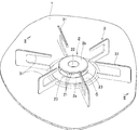
図1を参照して、1は、ガスコンロの天板を示しており、この天板1上に、バーナ2と、バーナ2を囲うようにして複数の五徳爪31を有する五徳3とが配置されている。バーナ2は、外周形状が平面視円形であって、外周面に周方向の間隔を存して多数の炎孔21を有し、且つ、中央部に上下方向の貫通穴22を有する環状に形成されている。
Referring to FIG. 1,
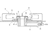
図2も参照して、より具体的に説明すれば、バーナ2は、環状のバーナボディ2aと、バーナボディ2a上に所定の位相で載置される環状のバーナキャップ2bとで構成されており、バーナボディ2aの外周面に炎孔21を形成している。また、天板1の下には、ガスノズル41を臨ませた上流端の流入口42を有する混合管4が設置されている。混合管4の下流端部43は、上方に屈曲する内外2重の筒状に形成されており、この下流端部43を天板1に開設した開口11を通して天板1上に突出させている。そして、混合管4の下流端部43の上端にバーナボディ2aを接続して、混合気がバーナ2に供給されると共に、バーナ2がその底面、即ち、バーナボディ2aの底面を天板1から浮かせた状態で支持されるようにしている。
More specifically, referring also to FIG. 2, the
また、天板1とバーナ2底面(バーナボディ2aの底面)との間の上下方向位置に、バーナ2外周面よりも径方向外方に張り出す環状の遮熱板5を設けている。遮熱板5は、バーナボディ2aの底面の周方向複数個所に垂設した突起23の下端にかしめ等で固定されている。そして、遮熱板5と天板1との間の空隙が遮熱板5の内周空間(遮熱板5の径方向内方の空間)を介して遮熱板5とバーナボディ2aの底面との間の空隙に連通するようにしている。尚、遮熱板5を突起23と共にバーナボディ2aと一体成形することも可能である。
In addition, an annular
本実施形態によれば、バーナ2底面を天板1から浮かせているため、燃焼時のバーナ2から天板1への伝熱が抑制されると共に、バーナ2外周面の炎孔21に生ずる火炎からの輻射熱が天板1に及ぶことを遮熱板5により遮ることができる。更に、外方から遮熱板5と天板1との間の空隙に流入する空気が遮熱板5の内周空間と、遮熱板5とバーナ2底面との間の空隙とを介して下方からバーナ2外周面の炎孔21に二次空気として供給される。そのため、遮熱板5と天板1との間の空隙に燃焼中常に空気が流れることになり、この空気により天板1が冷却され、バーナ2から天板1への伝熱の抑制及び火炎からの輻射熱の遮熱と相俟って天板1の過熱を効果的に防止できる。
According to the present embodiment, since the bottom surface of the
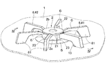
次に、図3、図4に示す第2実施形態について説明する。第2実施形態の基本的な構造は上記第1実施形態のものと特に異ならず、第1実施形態と同様の部材、部位に上記と同一の符号を付している。第2実施形態の第1実施形態との主たる相違点は、バーナ2、具体的にはバーナボディ2aに、放射状に外方にのびる複数の五徳爪6を一体に形成したことと、第1実施形態の混合管4に代えて、天板1上に、バーナ2に混合気を供給する、バーナ2から外方にのびる導管7を配置したことである。
Next, a second embodiment shown in FIGS. 3 and 4 will be described. The basic structure of the second embodiment is not particularly different from that of the first embodiment, and the same members and parts as those of the first embodiment are denoted by the same reference numerals. The main difference between the second embodiment and the first embodiment is that the
各五徳爪6の外端部には、下方に屈曲して天板1に着座する脚部61が形成されている。そして、五徳爪6によりバーナ2がその底面を天板1から浮かせた状態で天板1上に支持されるようにしている。
Leg
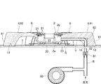
また、導管7の内端部(バーナ2側の端部)はバーナボディ2aに接続され、導管3の外端部は下方に屈曲して、天板1に形成した透孔12に連通している。透孔12には、天板1の下に配置したガス供給管8の下流端のガスノズル81が臨んでいる。ガスノズル81は、一次空気吸引筒82を具備しており、ガスノズル81からの燃料ガスの噴射に伴い一次空気吸引筒82に空気が吸引されて、混合気が透孔12を介して導管7に供給される。尚、一次空気が不足しないように、ガス供給管8にファン83から補助的に一次空気を供給するようにしている。
Further, the inner end portion (end portion on the
第2実施形態では、天板1上に突出する第1実施形態の如き混合管4が存在しないため、バーナ2を環状に形成することで、遮熱板5と天板1との間の空隙が遮熱板5の内周空間を介して遮熱板5とバーナ2底面との間の空隙に連通するだけでなく、バーナ2中央部の貫通穴22にも連通する。従って、遮熱板5と天板1との間の空隙に流入した空気が遮熱板5とバーナ2底面との間の空隙を介して下方から炎孔21に二次空気として供給されるだけでなく、貫通穴22を経由しバーナ2上面と五徳爪7に載置した調理容器の底面との間の空隙を介して上方からも炎孔21に二次空気として供給される。その結果、遮熱板5と天板1との間の空隙に流れる空気量が多くなり、天板1が効率よく冷却される。
In the second embodiment, since there is no
更に、第2実施形態では、五徳爪6がバーナ2に一体であるため、第1実施形態の如き五徳3が不要となって、部品点数を削減できる。また、一般的に、五徳爪と同一方位に位置するバーナ外周面の部分は、五徳爪に火炎が触れないように、炎孔を形成しないか或いは小さな炎孔を形成する特定部位としている。これは第1実施形態のものも同様である。然し、第1実施形態の如くバーナ2と別体の五徳3を設ける場合には、五徳3の誤セットで五徳爪が特定部位から外れ、五徳爪に火炎が触れて燃焼不良を生ずることがある。これに対し、第2実施形態の如く五徳爪6をバーナ2と一体化すれば、バーナ2外周面の特定部位と五徳爪6との位置関係が保たれるため、五徳爪6が特定部位から外れることがなく、五徳爪6に火炎が触れることで発生する燃焼不良を確実に防止できる。
Furthermore, in the second embodiment, the
また、第2実施形態によれば、天板1上にバーナ2から外方にのびる導管7を配置するため、煮こぼれがかかりやすいバーナ2の配置部直下の天板1の部分に、第1実施形態の開口11の如き混合管等を挿通するための上下方向に貫通する開口を形成せずに済む。そのため、煮こぼれが開口からコンロ本体内に侵入することがなく、コンロ内部の耐久性が向上する。
Moreover, according to 2nd Embodiment, in order to arrange | position the conduit |
更に、第2実施形態では、導管7を、複数の五徳爪6のうちの所定の五徳爪である♯1の五徳爪6で覆われるように設けている。即ち、♯1の五徳爪6の下面及び脚部61の径方向内方を向く面に凹溝62を形成して、この凹溝62に導管7を嵌め込んでいる。これによれば、導管7が目隠しされて、体裁が良好になる。
Furthermore, in 2nd Embodiment, the conduit |
また、第2実施形態では、♯1の五徳爪6とその対角の♯2の五徳爪6が着座する天板1の部分に凹部13を形成して、五徳爪6及びバーナ2を位置決めできるようにしている。
Further, in the second embodiment, the
以上、本発明の実施形態について図面を参照して説明したが、本発明はこれに限定されるものではなく、本発明の趣旨を逸脱しない範囲で種々変形して実施することができる。例えば、上記実施形態では、バーナ2の外周形状が平面視円形であるが、六角形や八角形等の平面視多角形であってもよい。
As mentioned above, although embodiment of this invention was described with reference to drawings, this invention is not limited to this, Various deformation | transformation can be implemented in the range which does not deviate from the meaning of this invention. For example, in the above embodiment, the outer peripheral shape of the
1…天板、2…バーナ、21…炎孔、22…貫通穴、5…遮熱板、6…五徳爪。
DESCRIPTION OF
Claims (3)
バーナは、外周形状が平面視円形又は多角形であって、外周面に周方向の間隔を存して多数の炎孔を有し、バーナ底面が天板から浮いていて、天板とバーナ底面との間の上下方向位置に、バーナの外周面よりも径方向外方に張り出す環状の遮熱板が設けられ、遮熱板と天板との間の空隙が遮熱板の内周空間を介して遮熱板とバーナ底面との間の空隙に連通することを特徴とするガスコンロ。 A gas stove with a burner on the top,
The outer shape of the burner is circular or polygonal in plan view, and has a large number of flame holes on the outer peripheral surface with circumferential intervals, and the bottom surface of the burner floats from the top plate. An annular heat shield that projects radially outward from the outer peripheral surface of the burner is provided at a vertical position between the heat shield and the space between the heat shield and the top plate. A gas stove that communicates with a gap between the heat shield plate and the bottom surface of the burner via a heat exchanger.
Priority Applications (1)
| Application Number | Priority Date | Filing Date | Title |
|---|---|---|---|
| JP2015082613A JP2016200375A (en) | 2015-04-14 | 2015-04-14 | Gas cooking stove |
Applications Claiming Priority (1)
| Application Number | Priority Date | Filing Date | Title |
|---|---|---|---|
| JP2015082613A JP2016200375A (en) | 2015-04-14 | 2015-04-14 | Gas cooking stove |
Publications (1)
| Publication Number | Publication Date |
|---|---|
| JP2016200375A true JP2016200375A (en) | 2016-12-01 |
Family
ID=57423514
Family Applications (1)
| Application Number | Title | Priority Date | Filing Date |
|---|---|---|---|
| JP2015082613A Pending JP2016200375A (en) | 2015-04-14 | 2015-04-14 | Gas cooking stove |
Country Status (1)
| Country | Link |
|---|---|
| JP (1) | JP2016200375A (en) |
Cited By (4)
| Publication number | Priority date | Publication date | Assignee | Title |
|---|---|---|---|---|
| JP2021085631A (en) * | 2019-11-29 | 2021-06-03 | リンナイ株式会社 | Gas cooking stove |
| US11402101B2 (en) | 2020-08-14 | 2022-08-02 | Haier Us Appliance Solutions, Inc. | Cooktop appliance with a gas burner assembly having a thermal break |
| US11747020B2 (en) | 2021-08-11 | 2023-09-05 | Haier Us Appliance Solutions, Inc. | Cooktop and insulated burner assembly |
| US12516808B2 (en) | 2023-01-12 | 2026-01-06 | Haier Us Appliance Solutions, Inc. | Gas burner assembly and cooktop appliance |
-
2015
- 2015-04-14 JP JP2015082613A patent/JP2016200375A/en active Pending
Cited By (5)
| Publication number | Priority date | Publication date | Assignee | Title |
|---|---|---|---|---|
| JP2021085631A (en) * | 2019-11-29 | 2021-06-03 | リンナイ株式会社 | Gas cooking stove |
| JP7384648B2 (en) | 2019-11-29 | 2023-11-21 | リンナイ株式会社 | Gas stove |
| US11402101B2 (en) | 2020-08-14 | 2022-08-02 | Haier Us Appliance Solutions, Inc. | Cooktop appliance with a gas burner assembly having a thermal break |
| US11747020B2 (en) | 2021-08-11 | 2023-09-05 | Haier Us Appliance Solutions, Inc. | Cooktop and insulated burner assembly |
| US12516808B2 (en) | 2023-01-12 | 2026-01-06 | Haier Us Appliance Solutions, Inc. | Gas burner assembly and cooktop appliance |
Similar Documents
| Publication | Publication Date | Title |
|---|---|---|
| US6082994A (en) | Gas burner for cooking apparatus | |
| JP2016200375A (en) | Gas cooking stove | |
| US20170370575A1 (en) | A gas burner assembly | |
| JP5090499B2 (en) | Stove burner | |
| JP2011196556A (en) | Plate-type burner for boiler | |
| JP5432698B2 (en) | Gas burner for stove | |
| JP2008151493A (en) | Gas cooking stove | |
| CN109595556B (en) | Stove burner | |
| JP4481182B2 (en) | Gas stove | |
| CN107559825B (en) | Burner and gas cooker | |
| CN105737148A (en) | Combustor and gas stove | |
| KR101794572B1 (en) | Oil boiler having combustion gas flow guide | |
| JP2016200374A (en) | Gas cooking stove | |
| CN109724082B (en) | High-efficiency burner | |
| CN203785015U (en) | High energy-collecting type gas stove | |
| JP6429140B2 (en) | Combustion accelerator | |
| JP2017106683A (en) | Burner for cooking stove and cooking stove including the same | |
| US20060154193A1 (en) | Advanced commercial range burner | |
| JP5234842B2 (en) | Stove | |
| JP6131505B2 (en) | Stove burner | |
| JP5844789B2 (en) | Gas stove | |
| CN222560076U (en) | Burners and gas stoves | |
| JP2016011823A (en) | Stove burner | |
| JP6562636B2 (en) | Gas stove combustor | |
| KR102167391B1 (en) | Gas burner |