JP2016198119A - Ultrasonic imaging apparatus - Google Patents
Ultrasonic imaging apparatus Download PDFInfo
- Publication number
- JP2016198119A JP2016198119A JP2013171569A JP2013171569A JP2016198119A JP 2016198119 A JP2016198119 A JP 2016198119A JP 2013171569 A JP2013171569 A JP 2013171569A JP 2013171569 A JP2013171569 A JP 2013171569A JP 2016198119 A JP2016198119 A JP 2016198119A
- Authority
- JP
- Japan
- Prior art keywords
- transmission
- phasing
- reception
- delay
- data
- Prior art date
- Legal status (The legal status is an assumption and is not a legal conclusion. Google has not performed a legal analysis and makes no representation as to the accuracy of the status listed.)
- Pending
Links
Images


Classifications
-
- G—PHYSICS
- G01—MEASURING; TESTING
- G01S—RADIO DIRECTION-FINDING; RADIO NAVIGATION; DETERMINING DISTANCE OR VELOCITY BY USE OF RADIO WAVES; LOCATING OR PRESENCE-DETECTING BY USE OF THE REFLECTION OR RERADIATION OF RADIO WAVES; ANALOGOUS ARRANGEMENTS USING OTHER WAVES
- G01S7/00—Details of systems according to groups G01S13/00, G01S15/00, G01S17/00
- G01S7/52—Details of systems according to groups G01S13/00, G01S15/00, G01S17/00 of systems according to group G01S15/00
- G01S7/52017—Details of systems according to groups G01S13/00, G01S15/00, G01S17/00 of systems according to group G01S15/00 particularly adapted to short-range imaging
- G01S7/52046—Techniques for image enhancement involving transmitter or receiver
- G01S7/52047—Techniques for image enhancement involving transmitter or receiver for elimination of side lobes or of grating lobes; for increasing resolving power
-
- A—HUMAN NECESSITIES
- A61—MEDICAL OR VETERINARY SCIENCE; HYGIENE
- A61B—DIAGNOSIS; SURGERY; IDENTIFICATION
- A61B8/00—Diagnosis using ultrasonic, sonic or infrasonic waves
- A61B8/44—Constructional features of the ultrasonic, sonic or infrasonic diagnostic device
- A61B8/4483—Constructional features of the ultrasonic, sonic or infrasonic diagnostic device characterised by features of the ultrasound transducer
- A61B8/4488—Constructional features of the ultrasonic, sonic or infrasonic diagnostic device characterised by features of the ultrasound transducer the transducer being a phased array
-
- G—PHYSICS
- G01—MEASURING; TESTING
- G01S—RADIO DIRECTION-FINDING; RADIO NAVIGATION; DETERMINING DISTANCE OR VELOCITY BY USE OF RADIO WAVES; LOCATING OR PRESENCE-DETECTING BY USE OF THE REFLECTION OR RERADIATION OF RADIO WAVES; ANALOGOUS ARRANGEMENTS USING OTHER WAVES
- G01S15/00—Systems using the reflection or reradiation of acoustic waves, e.g. sonar systems
- G01S15/88—Sonar systems specially adapted for specific applications
- G01S15/89—Sonar systems specially adapted for specific applications for mapping or imaging
- G01S15/8906—Short-range imaging systems; Acoustic microscope systems using pulse-echo techniques
- G01S15/8909—Short-range imaging systems; Acoustic microscope systems using pulse-echo techniques using a static transducer configuration
- G01S15/8915—Short-range imaging systems; Acoustic microscope systems using pulse-echo techniques using a static transducer configuration using a transducer array
- G01S15/8927—Short-range imaging systems; Acoustic microscope systems using pulse-echo techniques using a static transducer configuration using a transducer array using simultaneously or sequentially two or more subarrays or subapertures
-
- G—PHYSICS
- G01—MEASURING; TESTING
- G01S—RADIO DIRECTION-FINDING; RADIO NAVIGATION; DETERMINING DISTANCE OR VELOCITY BY USE OF RADIO WAVES; LOCATING OR PRESENCE-DETECTING BY USE OF THE REFLECTION OR RERADIATION OF RADIO WAVES; ANALOGOUS ARRANGEMENTS USING OTHER WAVES
- G01S15/00—Systems using the reflection or reradiation of acoustic waves, e.g. sonar systems
- G01S15/88—Sonar systems specially adapted for specific applications
- G01S15/89—Sonar systems specially adapted for specific applications for mapping or imaging
- G01S15/8906—Short-range imaging systems; Acoustic microscope systems using pulse-echo techniques
- G01S15/8997—Short-range imaging systems; Acoustic microscope systems using pulse-echo techniques using synthetic aperture techniques
-
- G—PHYSICS
- G01—MEASURING; TESTING
- G01S—RADIO DIRECTION-FINDING; RADIO NAVIGATION; DETERMINING DISTANCE OR VELOCITY BY USE OF RADIO WAVES; LOCATING OR PRESENCE-DETECTING BY USE OF THE REFLECTION OR RERADIATION OF RADIO WAVES; ANALOGOUS ARRANGEMENTS USING OTHER WAVES
- G01S7/00—Details of systems according to groups G01S13/00, G01S15/00, G01S17/00
- G01S7/52—Details of systems according to groups G01S13/00, G01S15/00, G01S17/00 of systems according to group G01S15/00
- G01S7/52017—Details of systems according to groups G01S13/00, G01S15/00, G01S17/00 of systems according to group G01S15/00 particularly adapted to short-range imaging
- G01S7/52085—Details related to the ultrasound signal acquisition, e.g. scan sequences
Landscapes
- Engineering & Computer Science (AREA)
- Physics & Mathematics (AREA)
- Radar, Positioning & Navigation (AREA)
- Remote Sensing (AREA)
- Computer Networks & Wireless Communication (AREA)
- General Physics & Mathematics (AREA)
- Acoustics & Sound (AREA)
- Health & Medical Sciences (AREA)
- Life Sciences & Earth Sciences (AREA)
- Pathology (AREA)
- Medical Informatics (AREA)
- Nuclear Medicine, Radiotherapy & Molecular Imaging (AREA)
- Gynecology & Obstetrics (AREA)
- Radiology & Medical Imaging (AREA)
- Biomedical Technology (AREA)
- Heart & Thoracic Surgery (AREA)
- Biophysics (AREA)
- Molecular Biology (AREA)
- Surgery (AREA)
- Animal Behavior & Ethology (AREA)
- General Health & Medical Sciences (AREA)
- Public Health (AREA)
- Veterinary Medicine (AREA)
- Ultra Sonic Daignosis Equipment (AREA)
Abstract
Description
本発明は、超音波を用いて被検体内の画像を撮像する超音波撮像技術に関する。 The present invention relates to an ultrasound imaging technique for capturing an image in a subject using ultrasound.
超音波撮像技術とは、超音波(聞くことを意図しない音波、一般的には20kHz以上の高周波数の音波)を用いて人体をはじめとする被検体の内部を非侵襲的に画像化する技術である。 The ultrasound imaging technique is a technique for non-invasively imaging the inside of a subject such as a human body using ultrasound (a sound wave not intended to be heard, generally a sound wave having a high frequency of 20 kHz or higher). It is.
超音波撮像装置による超音波の送受信は、有限の開口径を持つアレイによって行われるため、開口部のエッジによる超音波の回折の影響を受け、方位角方向の分解能を向上させることが難しい。この問題は、無限に長いアレイを用意できれば解決できるが、現実的には実現は困難である。そのため近年では、方位角方向の分解能向上のために、チャンネルドメイン整相技術の検討が盛んに行われており、適応ビームフォーマや、開口合成などの新しい整相方式が盛んに報告されている。 Since ultrasonic transmission / reception by the ultrasonic imaging apparatus is performed by an array having a finite aperture diameter, it is difficult to improve the resolution in the azimuth direction due to the influence of ultrasonic diffraction by the edge of the aperture. This problem can be solved if an infinitely long array can be prepared, but in reality it is difficult to realize. Therefore, in recent years, channel domain phasing techniques have been actively studied to improve the resolution in the azimuth direction, and new phasing methods such as adaptive beamformers and aperture synthesis have been actively reported.
開口合成を簡単に説明する。まず、超音波探触子を構成する複数素子の受信信号にそれぞれ遅延時間を与えることにより、仮想的にある点について焦点を合わせた後、加算して得た整相信号を得る。この整相信号と同一点について他の1以上の送受信で得た整相信号とを合成し、重ね合わせることにより開口合成を行う。 The aperture synthesis will be briefly described. First, a delay time is given to each of the reception signals of a plurality of elements constituting the ultrasonic probe, thereby focusing on a certain point and then obtaining a phasing signal obtained by addition. Aperture synthesis is performed by synthesizing and superimposing the phasing signal and the phasing signal obtained by one or more other transmissions / receptions at the same point.
開口合成は、ある点に対して異なる方向から超音波探触子が送受信して得た整相信号を重ね合わせることができるため、点像の高解像度化、不均質に対する頑健性などを付与することが期待される。さらには、重ね合わせ処理により処理利得が向上するため、超音波の送信回数を通常よりも間引いた送信が可能となり、高速撮像にも応用できる。 Aperture synthesis can superimpose phasing signals obtained by transmitting and receiving ultrasonic probes from different directions to a point, giving high resolution of point images and robustness against inhomogeneities. It is expected. Furthermore, since the processing gain is improved by the superimposition processing, it is possible to perform transmission by thinning out the number of ultrasonic transmissions more than usual, and it can be applied to high-speed imaging.
特許文献1の発明は、ハードウェアの増加やフレームレートの低下を回避しつつ、多方向から撮影した場合と同等の断層像を得ることを目的としている。特許文献1では、複数の超音波素子の受信信号のうち強度が最も大きな信号の超音波素子の位置から、超音波の主反射角を求め、主反射角を中心に受信信号を重み付けした後加算して整相する技術が開示されている。
An object of the invention of
本発明においては、これまでの開口合成方式がもつ以下の二つの課題を解決する。 The present invention solves the following two problems of the conventional aperture synthesis method.
第一の課題は、開口合成が複数の送信ごとに得た受信信号の整相信号を合成する、すなわち送信間で整相信号の合成を行うため,受信信号に含まれるシステム雑音等のシステム(機器)に起因する誤差が送信間でばらつく場合、その影響を大きく受けることである。発明者は,システムに起因する受信信号の誤差の送信間でのばらつきが、開口合成で超音波画像を生成する際に無視できない画像の誤差となることを見いだした。システムに起因する誤差の送信間でのばらつきは、装置個体によって異なり、また同じ装置においても,プローブの経年劣化,アナログ送受信回路の不具合などによって変化する。よって,複数送信間という時間方向の受信信号の誤差解消技術を用意する必要がある。 The first problem is to synthesize the phasing signal of the received signal obtained by aperture synthesis for each of a plurality of transmissions, that is, to synthesize the phasing signal between transmissions. If the error caused by (device) varies between transmissions, it is greatly affected. The inventor has found that the variation of the received signal error caused by the system between transmissions becomes an image error that cannot be ignored when generating an ultrasonic image by aperture synthesis. Variations in transmission of errors caused by the system vary between individual devices, and even in the same device, change due to aging degradation of the probe, failure of the analog transmission / reception circuit, and the like. Therefore, it is necessary to prepare a technique for eliminating the error of the received signal in the time direction between multiple transmissions.
第二の課題は、高速撮像のために、超音波の送信回数を通常よりも間引いた送信を行う場合、送信した超音波の照射領域の送信間の重なりが少なくなるため、開口合成を行った場合に、ブロッキングノイズが生じることである。この問題は、拡散送信よりも集束送信の方が、送信焦点付近で照射領域が狭まるため顕著であり、焦点付近でX字型のブロッキングアーチファクトが生じる。この課題も、本質的には第一の課題と同じように、送信間での受信信号のばらつきを低減することで解消することが可能である。 The second problem is that, for high-speed imaging, aperture transmission was performed because there was less overlap between transmissions in the irradiated area of the transmitted ultrasonic waves when transmission was performed with the number of ultrasonic transmissions reduced than usual. In some cases, blocking noise occurs. This problem is more conspicuous in the focused transmission than in the diffuse transmission because the irradiation area is narrow near the transmission focal point, and an X-shaped blocking artifact occurs near the focal point. This problem can also be solved by reducing the variation in the received signal between transmissions, as in the first problem.
これら第一および第二の課題は,送信間で合成を行わず,一送信ごとの受信信号で画像を生成する方法では顕在化してこなかった。なぜならば,チャンネル方向に受信信号を加算処理することにより、たとえ送受信のシステムに起因する誤差により送信間で受信信号のばらつきが発生していたとしても,最終的に超音波画像の中でその影響が現れてこないためである。 These first and second problems have not been realized by a method of generating an image with a received signal for each transmission without performing synthesis between transmissions. This is because, by adding the received signal in the channel direction, even if there is a variation in the received signal between transmissions due to an error caused by the transmission / reception system, the influence is finally included in the ultrasonic image. This is because does not appear.
特許文献1に開示されている技術は、複数素子の受信信号ごとに重み付けをして加算することにより整相するものであり、複数送信間で整相後信号を加算する開口合成処理は行っていない。
The technique disclosed in
本発明の目的は、開口合成処理において、送信間における受信信号のばらつきを低減し、高精度の画像を得ることにある。 An object of the present invention is to reduce variations in received signals between transmissions in aperture synthesis processing and obtain a highly accurate image.
本発明の超音波撮像装置は、開口合成処理を行う受信ビームフォーマを有し、受信ビームフォーマは、1送信ごとの前記受信信号を1以上の受信焦点のそれぞれについて遅延および加算して整相する遅延加算整相部と、遅延加算整相部による受信焦点ごとの遅延整相データを送信ごとに格納するビームメモリと、ビームメモリに格納された送信ごとの遅延整相データのうち同一の受信焦点についての遅延整相データを読み出して合成する送信間合成部とを備えている。 The ultrasonic imaging apparatus according to the present invention includes a reception beamformer that performs aperture synthesis processing, and the reception beamformer delays and adds the reception signal for each transmission for each of one or more reception focal points, and phase adjusts the received signal. Delay addition and phasing unit, beam memory storing delay phasing data for each reception focus by delay addition phasing unit for each transmission, and the same reception focus among delay phasing data for each transmission stored in beam memory And an inter-transmission combiner that reads and combines the delayed phasing data.
送信間合成部では,同一の受信焦点についての送信ごとの遅延整相データにそれぞれの重み係数をかけて重み付けした後、合成する。 The inter-transmission combiner weights the delayed phasing data for each transmission with respect to the same reception focus by applying the respective weighting factors, and then combines them.
本発明によれば、開口合成処理において、送信間における受信信号のばらつきを重み付けにより低減することができるため、高精度の画像が得られる。 According to the present invention, it is possible to reduce variations in received signals between transmissions by weighting in aperture synthesis processing, so that a highly accurate image can be obtained.
本発明の一実施形態の超音波撮像装置について説明する。 An ultrasonic imaging apparatus according to an embodiment of the present invention will be described.
(第1の実施形態)
第1の実施形態の超音波撮像装置について、図1、図2(a),(b)を用いて説明する。図1は、装置の一部のブロック図、図2(a)は装置の斜視図、図2(b)は装置全体の概略構成を示すブロック図である。
(First embodiment)
The ultrasonic imaging apparatus according to the first embodiment will be described with reference to FIGS. 1, 2A and 2B. 1 is a block diagram of a part of the apparatus, FIG. 2A is a perspective view of the apparatus, and FIG. 2B is a block diagram showing a schematic configuration of the entire apparatus.
図1および図2(a),(b)に示すように、第1の実施形態の超音波撮像装置は、所定の方向に沿って複数の超音波素子105を配列した超音波素子アレイ101と、複数の超音波素子105の少なくとも一部(201,202,203)から超音波を送信させる送信ビームフォーマ104と、被検体100からの超音波を受信した複数の超音波素子105の出力する受信信号を整相する受信ビームフォーマ108と、受信ビームフォーマの出力する整相出力を用いて画像データを生成する画像処理部109とを有する。
As shown in FIG. 1 and FIGS. 2A and 2B, the ultrasonic imaging apparatus of the first embodiment includes an
受信ビームフォーマ108は、開口合成処理を行うビームフォーマである。図1のように、受信ビームフォーマ108は、1送信ごとの受信信号を1以上の受信焦点のそれぞれについて遅延および加算して整相する遅延加算整相部204と、遅延加算整相部204による受信焦点ごとの遅延整相データを送信ごとに格納するビームメモリ206と、ビームメモリ206に格納された送信ごとの遅延整相データのうち同一の受信焦点について遅延整相データを読み出して合成する送信間合成部205とを備えている。
The
送信間合成部205では,同一の受信焦点についての送信ごとの遅延整相データにそれぞれの重み係数をかけて重み付けした後、合成する。これにより、システム(装置の機器)に起因する誤差が送信間でばらつくことにより、遅延整相データに誤差が生じ、開口合成後の信号に無視できない誤差を生じることを抑制することができる。よって、解像度の高い超音波画像を開口合成により得ることができる。また、超音波の送信回数を通常よりも間引いて高速撮像を行う場合に、送信間の照射領域の重なりが少なくても、開口合成により生じるアーチファクトを防止し、解像度の高い超音波画像を得ることができる。
The inter-transmission synthesizing
超音波撮像装置は、あらかじめ定められた重み係数を格納した重みメモリ112を備える構成とすることができる。これにより、送信間合成部205は、重みメモリから重み係数を読み出して重み付けに用いることが可能になる。
The ultrasonic imaging apparatus may include a
以下、第1の実施形態の超音波撮像装置をさらに具体的に説明する。 Hereinafter, the ultrasonic imaging apparatus according to the first embodiment will be described more specifically.
図1および図2(a),(b)を用いて超音波撮像装置の全体構成についてさらに説明する。 The overall configuration of the ultrasonic imaging apparatus will be further described with reference to FIGS. 1 and 2A and 2B.
図2(a)のように、超音波撮像装置は、超音波探触子106と、装置本体102と、画像表示部103と、コンソール110を備えている。装置本体102内には、図2(b)のように送信ビームフォーマ104と、送受信分離回路(T/R)107と、受信ビームフォーマ108と、画像処理部109と、これらの動作を制御する制御部111が配置されている。重みメモリ112は、制御部111内に配置されている。
As shown in FIG. 2A, the ultrasonic imaging apparatus includes an
受信ビームフォーマ108は、図1のように、上述の遅延加算整相部204、ビームメモリ206、送信間合成部205の他に、演算に用いる重み係数を重みメモリ112から一時的に取り込んで格納する重みテーブル601と、フレームメモリ207とを備えている。超音波探触子106は、図1に示した超音波素子アレイ101を備えている。
As shown in FIG. 1, the
図2(b)の送信ビームフォーマ104は、超音波の送信ビームを生成するための送信ビーム用信号を生成する。送信ビーム用信号は、送受信分離回路107を経て、超音波探触子106に受け渡される。超音波探触子106は、超音波素子アレイ101の超音波素子105にそれぞれ送信ビーム用信号を受け渡す。超音波素子105は、超音波を被検体100の体内に向けて送信する。体内で反射されたエコー信号は、超音波探触子106の超音波素子アレイ101により受信される。受信信号は、再び送受信分離回路107を経て受信ビームフォーマ108において整相演算処理等が施される。
The transmission beam former 104 in FIG. 2B generates a transmission beam signal for generating an ultrasonic transmission beam. The transmission beam signal is transferred to the
遅延加算整相部204が行う整相処理を図3を用いて説明する。遅延加算整相部204は、送信ビームフォーマ104による一回の超音波の送信に対して超音波素子105が受信する受信データから、複数の受信ビーム(beam #1〜beam #M)を並列処理により生成する。本実施形態では、受信ビームとは、深さ方向に直線的に並べられた複数の受信焦点の集合を言う。明細書中および図面中において#は、番号(No.)を意味する符号として用いている。一般的には、受信ビーム(受信焦点の集合)の本数は、送信ビームの中心付近の1本、または、中心付近の2〜8本程度の数だけ形成される(パラレルビームフォーミング)。しかしながら、これらの本数に限定されるものではなく、超音波素子アレイ101の指向角10内に、何本形成してよい。指向角10(例えば90°)内に、32本,64本,128本等の受信ビームを並列に生成しても良い。
The phasing process performed by the delay
ここでは一例として、超音波素子アレイ101の中心を時刻ゼロとした場合の遅延法を用いて、遅延加算整相部204が受信ビームを生成する場合について説明する。なお、送信焦点位置を時刻ゼロとするような遅延法(仮想音源法)を用いて受信ビームを生成しても良い。
Here, as an example, a case will be described in which the delay and
図3において2番目の受信ビーム(beam #2)の受信焦点11aについて受信信号を整相する場合,遅延加算整相部204が超音波素子アレイ101のアクティブチャンネルの超音波素子105の受信信号のそれぞれに、図3に示す遅延カーブ12aで表される遅延時間を適用して遅延させる。同様に、受信焦点11bについて受信信号を整相する場合には、遅延カーブ12bで表される遅延時間を適用して受信信号を遅延させる。また、m番目の受信ビーム(beam #m)の上の受信焦点13a,13bについて整相を行う場合には,それぞれ図3の遅延カーブ14a,14bで表される遅延時間を適用して受信信号を遅延させる。
In FIG. 3, when phasing the reception signal for the
遅延加算整相部204は、受信信号をそれぞれ遅延させた後、加算する。これにより、一つの受信焦点について遅延整相データが得られる。この演算を受信ビーム上に設定した全ての受信焦点について行うことにより、一つの受信ビームについて、遅延整相データの集合が得られる。
The delay
この演算を、M本の受信ビーム(beam #1〜beam # M)上の全ての受信焦点について行うことにより、扇形領域15の受信焦点の遅延整相データを生成することができる。すなわち、超音波素子アレイ101からの一回の超音波の送信および受信によって、M本の並列な受信ビームの集合体としての扇形領域15の像(すなわち、受信焦点の集合)が生成される。なお受信ビームの集合体の形状は、扇型形状であっても、超音波素子105それぞれの表層面の法線ベクトル方向にビーム方向を選んだような受信ビーム形状であっても良い。また、超音波素子105が送信する送信ビームの範囲内を網羅するような任意の複数ビームの集合体であってもよい。また、図3においては超音波素子105は直線上に配置されたリニア型の形状であるが、素子配置が湾曲したコンベックス形状であってもよい。また、送信ビームの走査方式がセクタ型であっても良い。
By performing this calculation for all reception focal points on the M reception beams (
求められた各受信焦点の遅延整相データは、遅延加算整相部204から送信間合成部205を通して受信ビームごとにビームメモリ206に蓄積される。よって、ビームメモリ206内には、超音波の送受信ごとに、M本の受信ビームの受信焦点の遅延整相データから構成される扇形領域15の像が、1つ蓄えられる。ビームメモリ206のメモリ量は有限であるため、新しい送受信で得た受信ビームの遅延整相データを蓄えるために、最も時間が古い受信ビームの遅延整相データを消去して更新する構成とする。ただし、超音波撮像を行っている時間中のすべての送受信で得た遅延整相データを蓄えるのに十分なメモリ量を持っている場合には、古いデータを消去する必要はなく、全ての遅延整相データをビームメモリ206内に蓄える。
The obtained delay phasing data for each reception focus is accumulated in the
次に、送信間合成部205の動作を図4を用いて説明する。送信間合成部205は、ビームメモリ206に蓄えられた遅延整相データのうち、異なる送信で同じ位置の受信焦点について得た遅延整相データを合成することで、開口合成画像を生成する。
Next, the operation of the
まず、最終的に形成したい開口合成画像を、図4(c)のように定める。図4(c)の開口合成画像は、J本の走査線(Scan line #1 〜 Scan line #J)から構成される。それぞれの走査線は、深さ方向にS個の受信焦点(σ=1,2,・・・S)を含む。なお、明細書および図4において、φは、走査線番号を表す符号として、σは、受信焦点の番号を表す符号として、nは、送信(Tx)の番号を示す符号として用いている。
First, an aperture composite image to be finally formed is determined as shown in FIG. The aperture composite image in FIG. 4C is composed of J scan lines (
この開口合成画像中の受信焦点と同一の位置の受信焦点の遅延整相データをビームメモリ206から読み出して合成する。例えば、開口合成画像の走査線の方向および受信焦点の間隔が、遅延加算整相部204で計算される受信ビームの方向と受信焦点の間隔にそれぞれ対応している場合、送信番号1,2・・・Nで得られた扇形領域の像には、開口合成画像のj番目の走査線のs番目の受信焦点24と同一位置の受信焦点21,22・・・23が図4(a)のように含まれる。送信間合成部205は、ビームメモリ206から受信焦点21,22・・・23の遅延整相データをそれぞれ読み出して合成する。
The delay phasing data of the reception focus at the same position as the reception focus in the aperture synthesized image is read from the
本実施形態では、遅延整相データの合成の際に、図4(b)のように送信間合成部205が、送信間の遅延整相データを重み付けして加算する。送信ごとの遅延整相データには、システム(機器)に起因する誤差によるばらつきや、高速撮像時のブロックノイズが存在するため、下記式(1)のように重みを乗じて、演算を行い合成することにより、この問題を解消する。
In the present embodiment, when synthesizing the delay phasing data, the

なお、式(1)において、R(j,s)は、開口合成画像のj番目の走査線のs番目の受信焦点の合成後の遅延整相データであり、r(j,s,n)は、送信番号nで得られた遅延整相データであって、開口合成画像のR(j,s)と同一の位置にある受信焦点の遅延整相データである。w(j,s,n)は、遅延整相データr(j,s,n)に重み付けする重み係数を表し、重みテーブル601に格納されている重み係数である。すなわち、重み係数w(j,s,n)は、送信番号、走査線番号および受信焦点番号ごとに個別の重み係数が設定されている。 In Equation (1), R (j, s) is delayed phasing data after synthesis of the s-th reception focus of the j-th scanning line of the aperture synthesized image, and r (j, s, n). Is the delay phasing data obtained with the transmission number n, and is the delay phasing data of the reception focal point at the same position as R (j, s) of the aperture synthetic image. w (j, s, n) represents a weighting factor for weighting the delay phasing data r (j, s, n), and is a weighting factor stored in the weighting table 601. That is, as the weighting coefficient w (j, s, n), individual weighting coefficients are set for each transmission number, scanning line number, and reception focus number.
なお、開口合成画像の走査線の方向および受信焦点の間隔は、遅延加算整相部204で計算される受信ビームの方向と受信焦点の間隔にそれぞれ対応しない場合もある。このような場合には、開口合成画像の受信焦点に最も近い受信ビームの受信焦点の遅延整相データをそのままr(j,s,n)として用いてもよいし、バイリニア補間のような線形補間、もしくはバイキュービック補間のような非線形補間を利用して、開口合成画像の受信焦点に近い位置の遅延整相データの値からr(j,s,n)を補間演算により求めて用いても良い。
Note that the direction of the scanning line of the aperture synthesized image and the interval between the reception focal points may not correspond to the direction of the reception beam and the interval between the reception focal points calculated by the delay
つぎに、図5を用いて重みテーブル601に格納される重み係数について説明する。本実施形態では、全ての走査線1〜Jの全ての受信焦点について、送信ごとに重み係数を用意することに特徴がある。
Next, the weight coefficients stored in the weight table 601 will be described with reference to FIG. The present embodiment is characterized in that weight coefficients are prepared for each transmission for all reception focal points of all
開口合成画像の走査線の総数がJ本、1本の走査線上の受信焦点の数がS個、一つの開口合成に用いる送信回数がN回である場合、図5(a)のように重みテーブル601は、S×N個の重み係数の値を格納可能なテーブルを、走査線の総数であるJ個格納可能な記憶領域を備えている。すなわち、一つのテーブルには、一つの走査線上のS個の受信焦点のそれぞれの重みが、N回の送信回数の分だけ格納されている。例えば、図5(a)のように開口合成画像の2番目の走査線のs番目の受信焦点61についての1回〜N回の送信ごとの重み係数は,図5(b)の2番目の走査線の重みテーブルの行62に格納されている。
When the total number of scanning lines of the aperture synthetic image is J, the number of reception focal points on one scanning line is S, and the number of transmissions used for one aperture synthesis is N, the weights are as shown in FIG. The table 601 includes a storage area that can store J values, which is the total number of scanning lines, and can store S × N weighting coefficient values. That is, in each table, the weights of the S reception focal points on one scanning line are stored for N transmissions. For example, as shown in FIG. 5A, the weighting coefficient for each transmission of 1 to N times with respect to the s-
なお、重みテーブル601は、必ずしも図5(b)の構成でなくてもよく、全送信回数,全受信焦点数および全走査線数について、それぞれ重み係数が格納できればよい。また、重みテーブル601内の重みデータが重複する場合にはその重複した分を取り除いた最小データ量の重みデータの組合せだけをもつような重みテーブル601であっても良い。 The weight table 601 does not necessarily have the configuration shown in FIG. 5B, and it is sufficient that weighting factors can be stored for the total number of transmissions, the total number of received focal points, and the total number of scanning lines. Further, when the weight data in the weight table 601 is duplicated, the weight table 601 may have only a combination of weight data of the minimum data amount from which the duplicated amount is removed.
重みテーブル内の重み係数は、設定可能な撮像条件ごとに、遅延整相データのシステムに起因するばらつきや、高速撮像時のブロックノイズが低減されるように最適な値を予め求めておき、制御部111内の重みメモリ112に格納しておく。制御部111は、操作者がコンソール110に設定した撮像条件に対応するテーブルを重みメモリ112から読み出して、重みテーブル601に格納する。
For the weighting factor in the weighting table, an optimal value is calculated in advance for each settable imaging condition so that variation due to the delay phasing data system and block noise during high-speed imaging are reduced. It is stored in the
つぎに、図6を用いて,本発明の超音波撮像装置の動作フローを説明する。 Next, the operation flow of the ultrasonic imaging apparatus of the present invention will be described with reference to FIG.
まず,装置の操作者(術者・検者)がコンソール110に撮像条件を入力すると、その撮像条件に従って,制御部111がプローブ条件・超音波照射条件・開口合成条件、の情報を示す制御信号を出力する。受信ビームフォーマ108が上記制御信号を受け取る(ステップS401)。
First, when an operator (operator / examiner) of the apparatus inputs imaging conditions to the
次に,制御部111は,上記の撮像条件に対応する重み係数のテーブルを選択し、受信ビームフォーマ108中の重みテーブル601にダウンロードする(ステップS402)。
Next, the
次に、超音波素子アレイ101において超音波の送受が行われる(ステップS403)。一回の送信で超音波素子105が受信した受信データは、遅延加算整相部204に伝達され,図3を用いて説明したような複数の受信ビームの受信焦点の遅延整相データの演算が行われる。求められた複数の受信ビームの受信焦点の遅延整相データは、ビームメモリ206に格納される(ステップS404)。
Next, transmission / reception of ultrasonic waves is performed in the ultrasonic element array 101 (step S403). The reception data received by the
上記のステップS403からS404のプロセスは,超音波の送信1回と受信1回のセットごとに繰り返して行われる。 The processes of steps S403 to S404 are repeated for each set of transmission and reception of ultrasonic waves.
次に,ビームメモリに蓄えられた複数送信間の遅延整相データと、重みテーブル内の重みデータは、送信間合成部205に送られる(ステップS405,S406)。 Next, the delay phasing data between a plurality of transmissions stored in the beam memory and the weight data in the weight table are sent to the inter-transmission combining unit 205 (steps S405 and S406).
送信間合成部205においては、図4を用いて説明したように、開口合成画像の走査線番号jのs番目の受信焦点の合成後の遅延整相データR(j,s)を、送信番号nで得られた遅延整相データであって、開口合成画像の受信焦点(走査線番号j、受信焦点番号s)と同一の位置にあるデータr(j,s,n)を、送信番号n、走査線番号j、受信焦点番号sの重み係数w(j,s,n)によって重み付けした後、他の送信番号で同様に演算した重み付け後の遅延整相データと加算して合成する(ステップS407)。
As described with reference to FIG. 4, the
送信間合成に関する3つのステップS405,S406,S407を,1フレームの開口合成画像の全て(J×S個)の受信焦点について繰り返す。 The three steps S405, S406, and S407 related to the inter-transmission synthesis are repeated for all (J × S) reception focal points of one frame of the aperture synthetic image.
送信間合成部205で合成された開口合成画像は、受信ビームフォーマ108内のフレームメモリ207に蓄えられる(ステップS408)。以上のプロセスで、受信ビームフォーマ108による処理が完了する。
The aperture synthesis image synthesized by the
フレームメモリ207中に蓄えられたフレームデータは、画像処理部109に送信される。画像処理部109はバックエンドの画像処理を行い、超音波画像(例えばB−モード画像)を生成して画像表示部103に出力する(ステップS409)。また、画像処理部109では、フレームメモリ207から送られてきたフレームデータを用いて,非線形撮像画像,造影コントラスト画像,連続波ドプラ画像,パルスドプラ画像,カラーフロー画像、エラストグラフィなどの弾性波画像など様々な超音波画像の生成やアプリケーションの実行を行うことができる。
The frame data stored in the
また、図6においては、制御部からの重み値のダウンロードは、全ての超音波の送信・受信の前にダウンロードされているが、ステップS402の動作は、ステップS406の直前に行われてもよく、送信間の合成処理の1回毎に行われても良い。その場合、ステップS402のブロックは、図6のステップS404とS406のブロックの間に配置され、ステップS402→S406→S407→S402の動作が、1フレーム完成まで繰り返される。また、この場合、重みテーブルに1回のダウンロード処理で転送される重みデータの容量は、ステップS407の送信間合成処理で必要なだけの容量に限ることができる。 In FIG. 6, the weight values are downloaded from the control unit before the transmission / reception of all the ultrasonic waves. However, the operation in step S <b> 402 may be performed immediately before step S <b> 406. Alternatively, it may be performed every time the combining process between transmissions is performed. In that case, the block of step S402 is arranged between the blocks of steps S404 and S406 in FIG. 6, and the operations of steps S402 → S406 → S407 → S402 are repeated until one frame is completed. In this case, the capacity of the weight data transferred to the weight table by one download process can be limited to a capacity necessary for the inter-transmission combining process in step S407.
本実施形態によれば、図7(a)のように、システムに起因する誤差や高速撮像時のブロックノイズによって送信回数ごとの信号強度にばらつきのある遅延整相データに、これを抑制するように予め定められた重み係数(図7(b))を乗じることにより、送信間でのばらつきを低減する(図7(c))。よって、重み係数を乗じた後の遅延整相データを加算することにより、システムに起因する誤差や高速撮像時のブロックノイズを低減した合成結果を得ることができる。 According to the present embodiment, as shown in FIG. 7A, the delay phasing data in which the signal intensity varies depending on the number of transmissions due to errors caused by the system and block noise during high-speed imaging is suppressed. Is multiplied by a predetermined weighting factor (FIG. 7B) to reduce the variation between transmissions (FIG. 7C). Therefore, by adding the delay phasing data after being multiplied by the weighting factor, it is possible to obtain a synthesis result in which errors caused by the system and block noise during high-speed imaging are reduced.
図8(a)は、拡散送信で低速撮像の場合の送信ビームの重なりを示し、図8(b)は、拡散送信で高速撮像の場合の送信ビームの重なりを示している。図8(c)は、低いF値のフォーカス送信(集束送信)で低速撮像の場合の送信ビームの重なりを示し、図8(d)は、低いF値のフォーカス送信で高速撮像の場合の送信ビームの重なりを示している。図8(b)、(d)の高速撮像の場合、送信ビーム同士の重なりが、低速撮像の場合よりも少なく、ブロッキングアーチファクトが生成されやすい。特に、図8(d)のフォーカス送信で高速撮像の場合には、焦点付近で送信ビーム同士の重なり少なく、顕著なブロッキングアーチファクトとして現れる。図8(b)、(d)のような高速撮像の場合であっても、本実施形態によれば、遅延整相データに重み係数を乗じて、送信間のばらつきを低減することができるため、ブロッキングアーチファクトを低減することができる。 8A shows the overlap of transmission beams in the case of low-speed imaging with spread transmission, and FIG. 8B shows the overlap of transmission beams in the case of high-speed imaging with spread transmission. FIG. 8C shows the overlap of transmission beams in the case of low-speed imaging with low F value focus transmission (focusing transmission), and FIG. 8D shows the transmission in the case of high-speed imaging with low F value focus transmission. The beam overlap is shown. In the case of the high-speed imaging shown in FIGS. 8B and 8D, the overlapping of transmission beams is smaller than that in the case of low-speed imaging, and blocking artifacts are likely to be generated. In particular, in the case of high-speed imaging with focus transmission in FIG. 8D, there is little overlap between transmission beams near the focal point, and it appears as a remarkable blocking artifact. Even in the case of high-speed imaging as shown in FIGS. 8B and 8D, according to the present embodiment, the delay phasing data can be multiplied by a weighting factor to reduce variation between transmissions. Blocking artifacts can be reduced.
また、本実施形態の開口合成処理は、一般的な開口合成処理と同様に、図4のようにアクティブチャンネル201、202,203の位置を少しずつずらしながら送信しているため、開口合成画像の走査線番号jのs番目の受信焦点24と同一位置の受信焦点21,22・・・23は、各送信で得た扇型領域15の像の異なる位置(異なる見込み角度、異なる受信ビーム番号)に存在する。これらのデータを合成することによって、受信焦点24を異なる方向から見込んで送信・受信した遅延整相データを重ね合わせることができるため、受信焦点24の遅延整相データの精度を向上させることができる。
Further, since the aperture synthesis processing of this embodiment is transmitted while shifting the positions of the
(比較例1)
比較例として、従来技術のように、送信間では重み付けを行わず、チャンネル方向(超音波素子の並び方向)と深さ方向に重み付けを行う場合の重みテーブルを図5(c)に示す。図5(c)の重みテーブルは、チャンネル方向と深さ方向の組み合わせのみでよいため、二次元のメモリ空間(テーブル)が一つのみでよい。
(Comparative Example 1)
As a comparative example, FIG. 5C shows a weight table in the case where weighting is not performed between transmissions as in the prior art, but weighting is performed in the channel direction (arrangement direction of ultrasonic elements) and the depth direction. Since the weight table in FIG. 5C only needs to be a combination of the channel direction and the depth direction, only one two-dimensional memory space (table) is required.
したがって、比較例の重みテーブルでは、図7(a)のように送信ごとに遅延整相データの信号強度にばらつきがある場合であっても、これを補正することができないため、システムに起因する誤差や高速撮像時のブロックノイズを低減した合成結果を得ることはできない。 Therefore, in the weight table of the comparative example, even if there is a variation in the signal strength of the delayed phasing data for each transmission as shown in FIG. 7A, this cannot be corrected, resulting in the system. It is not possible to obtain a synthesis result in which errors and block noise during high-speed imaging are reduced.
(第2の実施形態)
図9、図10を用いて第2の実施形態の超音波撮像装置について説明する。
(Second Embodiment)
The ultrasonic imaging apparatus according to the second embodiment will be described with reference to FIGS.
図9は、第2の実施形態の超音波撮像装置の一部のブロックであり、図10は、装置全体の斜視図である。第2の実施形態の超音波撮像装置は、重みメモリ112または重みテーブル601の重み係数の外部から書き換えを受け付けるための入出力ポート701を本体102に有する。本体102の外側には、重み係数を演算により求める重み係数演算部702が配置されている。重み係数演算部702は、入出力ポート701を介して重みメモリ112または重みテーブル601に接続され、重みメモリ112または重みテーブル601に格納されている重み係数を、演算により求めた重み係数に書き換える。
FIG. 9 is a partial block diagram of the ultrasonic imaging apparatus according to the second embodiment, and FIG. 10 is a perspective view of the entire apparatus. The ultrasonic imaging apparatus according to the second embodiment has an input /
重み係数演算部702は、ビームメモリ206から送信ごとの遅延整相データを受け取って重み係数を演算する構成にすることができる。例えば、重み係数演算部702は、送信ごとの遅延整相データを適応処理することにより、重み係数として適応重みを求める適応エンジン208を備える構成にする。重み係数演算部702には、適応エンジン208の他に制御部703が配置されている。制御部703は、適応エンジン208の動作の制御および入出力ポート701を介した遅延整相データや重み係数の本体102との信号のやり取りの制御を行う。
The weighting
図11に本実施形態の超音波撮像装置の動作フローを示す。図11の動作フローは、第1の実施形態の図6のステップS406、S407に替えて、ステップS505,S506、S507が行われる。他のステップは図6の説明と同様であるので説明を省略し、ステップS505,S506、S507について説明する。遅延整相データがビームメモリ206に格納されたならば、制御部111および制御部703の制御の下で、適応エンジン208が遅延整相データを受け取る(ステップS505)。適応エンジン208は、ビームメモリ206の遅延整相データを用いて、遅延整相データの送信間のばらつきに対応した最適な適応重みを求め、この適応重みを重みテーブル601の重み係数と書き換える(ステップS506)。送信間合成部205は、遅延整相データと適応重みを読み込んで、遅延整相データを適応重みで重み付けし、送信間で合成する(ステップS507)。
FIG. 11 shows an operation flow of the ultrasonic imaging apparatus of the present embodiment. In the operation flow of FIG. 11, steps S505, S506, and S507 are performed instead of steps S406 and S407 of FIG. 6 of the first embodiment. The other steps are the same as those described with reference to FIG. 6, and the description thereof will be omitted. Steps S505, S506, and S507 will be described. If the delay phasing data is stored in the
これにより、遅延整相データに応じた重み係数を用いて、遅延整相データの送信間のばらつきをより効果的に低減することができる。よって、システムに起因する誤差や高速撮像時のブロックノイズを低減した高解像度の超音波画像を生成することができる。 Thereby, the dispersion | variation between transmission of delay phasing data can be reduced more effectively using the weighting coefficient according to delay phasing data. Therefore, it is possible to generate a high-resolution ultrasonic image in which errors caused by the system and block noise during high-speed imaging are reduced.
また、求めた適応重みを、その時の撮像条件に対応させて重みメモリ112に格納していくことにより、装置ごとの遅延整相データのばらつきの差異や装置の経時変化に対応して、重みメモリ112内の重み係数を最適な値に更新していくことができる。なお、更新時には、画像表示部108に、重み係数演算部702により重み係数を更新中であることや、調整状態、調整の進捗などを表示することも可能である。また、この表示を重み係数演算部702に取り付けたインジケータ802に表示することも可能である。
In addition, by storing the obtained adaptive weight in the
本実施形態の重み係数演算部702は、本体102の外部に配置され、必要な時だけ、本体102に接続して、重みテーブル601の重み係数の書き換え、重みメモリ112の更新を行えばよい。よって、本体102内に重み係数演算部702を配置する場合と比較して、超音波画像診断装置を小型化することができる。また、複数の超音波画像診断装置で1台の重み係数演算部702を使い回すことができるというメリットもある。また、これにより、プローブの経年劣化,アナログ送受信回路の不具合などによって装置特性が変化する場合に、重み係数を変えることによるリフレッシュ動作を、装置の定期的なメンテナンス作業の一環として行う事ができる。
The weighting
次に、適応エンジン208における適応重みの計算(図11のステップS506)の演算方法について説明する。以下,j番目の走査線のs番目の受信焦点に対して適応重みを求める手順を説明する。
Next, the calculation method of adaptive weight calculation (step S506 in FIG. 11) in the
適応エンジン208への入力は、N回の送信で得た遅延整相データr(j,s,1),r(j,s,2),…,r(j,s,N)である。また適応エンジン208からの出力は,重み係数w(j,s,1),w(j,s,2),…,w(j,s,N)である。以下、説明を簡単にするために、jの表記は省き、入力される遅延整相データr(j,s,1),r(j,s,2),…,r(j,s,N)をベクトルr(s)=[r1(s),r2(s),…,rN(s)]とし,重み係数w(j,s,1),w(j,s,2),…,w(j,s,N)をベクトルw(s)=[r1(s),r2(s),…,rN(s)]と表す。
The input to the
適応エンジン208は、入力ベクトルrから共分散行列Γ(s)を以下の式(2)を用いて作成する。なお、式(2)において*は、共役複素数を表す。
The
また、ベクトルrの入力を時間サンプル方向に−T≦s≦Tの2T+1点の時間幅を持って入力することも可能であり、その場合アンサンブル平均をとることで、共分散行列Γ(s)は以下の式(3)で表すことができる。 It is also possible to input the vector r with a time width of 2T + 1 points of −T ≦ s ≦ T in the time sample direction. In this case, by taking an ensemble average, the covariance matrix Γ (s) Can be represented by the following formula (3).
これらの共分散行列を用いて、たとえばMVDR法による適応重みベクトルw(s)は、以下の式(4)から計算できる。 Using these covariance matrices, for example, the adaptive weight vector w (s) by the MVDR method can be calculated from the following equation (4).
式(4)において、aはステアリングベクトルであり,入力されるベクトルr(s)の方向に対する傾きであり,各送信番号nの位相関係から,式(5)のように表される。 In Expression (4), a is a steering vector, which is an inclination with respect to the direction of the input vector r (s), and is expressed as Expression (5) from the phase relationship of each transmission number n.
![]()
![]()
式(5)において、θは,位相周りが各送信番号間でゼロである場合をθ=0としたときの位相シフト量を表し,fは超音波の周波数である。一般的にθ=0として考えると,a=[1,1,…,1]と全ての要素が1のベクトルで表現することができ,このベクトルをステアリングベクトル方向とする。 In Expression (5), θ represents the phase shift amount when θ = 0 when the phase around the transmission numbers is zero, and f is the ultrasonic frequency. In general, when θ = 0, a = [1,1,..., 1] and all elements can be expressed by a vector of 1, and this vector is a steering vector direction.
適応エンジン208においては、以上のプロセスから,送信番号1〜Nに対応する重みベクトルw(s)=[r1(s),r2(s),…,rN(s)]を算出することができる(S506)。
In the
なお、適応重みの演算方法は、MVDR法に限られるものではなく、APES法,MUSIC法,ESMV法など各種重み生成プロセスを用いてw(s)を算出しても構わない。 Note that the adaptive weight calculation method is not limited to the MVDR method, and w (s) may be calculated using various weight generation processes such as the APES method, the MUSIC method, and the ESMV method.
また,ここで説明した適応重みの演算方法を用いて,第1の実施形態の重みメモリ112に格納する重み係数を超音波撮像条件ごとに計算することが可能である。
Also, using the adaptive weight calculation method described here, the weighting coefficient stored in the
(第3の実施形態)
図12、図13を用いて第3の実施形態の超音波撮像装置について説明する。図12は、第3の実施形態の超音波撮像装置の一部構成を示すブロック図であり、図13は、装置の斜視図と通信回線に接続されることを示す図である。
(Third embodiment)
The ultrasonic imaging apparatus according to the third embodiment will be described with reference to FIGS. FIG. 12 is a block diagram illustrating a partial configuration of the ultrasonic imaging apparatus according to the third embodiment, and FIG. 13 is a perspective view of the apparatus and a diagram illustrating connection to a communication line.
図12のように、第3の実施形態の超音波撮像装置は、第2の実施形態の図9の装置と似た構成であるが、図9の入出力ポート701に替えて、データを通信データに変換するためのデータ変換機能を備えた通信ポート901を本体102に配置している。また、重み係数演算部702にもデータ変換機能を備えた通信ポート903を配置している。
As shown in FIG. 12, the ultrasonic imaging apparatus of the third embodiment has a configuration similar to that of the apparatus of FIG. 9 of the second embodiment, but instead of the input /
これにより、本体102から離れた場所に重み係数演算部702が配置されていても、通信回線902やネットワークを介して両者を接続して、制御信号、遅延整相データおよび重み係数データをやり取りすることができるため、第2の実施形態と同様に重み係数の更新動作を行うことができる。よって、リモート制御で、重みメモリ112に格納されている重み係数を更新する動作を、遠隔操作による定期的な装置メンテナンスの一環として行うことが可能である。
As a result, even if the weighting
(第4の実施形態)
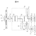
図14、図15を用いて第4の実施形態の超音波撮像装置について説明する。図14は第4の実施形態の超音波撮像装置の一部構成を示すブロック図であり、図15は、装置の動作フローを示す。
(Fourth embodiment)
An ultrasonic imaging apparatus according to the fourth embodiment will be described with reference to FIGS. 14 and 15. FIG. 14 is a block diagram showing a partial configuration of the ultrasonic imaging apparatus according to the fourth embodiment, and FIG. 15 shows an operation flow of the apparatus.
第4の実施形態の超音波撮像装置は、第1の実施形態の図1の装置の重みテーブルに替えて、送信ごとの遅延整相データを用いて重み係数を演算する重み係数演算部702を受信ビームフォーマ108の内部に備えている。重み係数演算部702は、送信ごとの遅延整相データを適応処理することにより、重み係数として適応重みを求める適応エンジン208を備えている。また、制御部111内には、重みメモリ112は配置されていない。
The ultrasonic imaging apparatus according to the fourth embodiment includes a weighting
適応エンジン208を備えた重み係数演算部702の動作は、第2の実施形態の重み係数演算部702と同様である。
The operation of the weighting
図15を用いて、超音波撮像装置の動作について説明する。図15からわかるように、装置の動作フローは、第3の実施形態の図11の動作フローと似ているが、重みメモリ112および重みテーブル601を備えないため、ステップS402を行わず、重み係数演算部702は、ビームメモリ206から直接遅延整相データを受け取る。また、ステップS505,S506により適応エンジン208が求めた適応重みは、直接送信間合成部205に受け渡す。送信間合成部205は、遅延整相データを適応重みで重み付けし、送信間で合成する(ステップS507)。
The operation of the ultrasonic imaging apparatus will be described with reference to FIG. As can be seen from FIG. 15, the operation flow of the apparatus is similar to the operation flow of FIG. 11 of the third embodiment, but since the
これにより、開口合成処理のたびに、ビームメモリ206に格納された遅延整相データから適応エンジン208が適応重みを演算により求めることができる。送信間合成部は、適応重みを用いて遅延整相データを重み付けして合成することができるため、システムに起因する誤差や高速撮像時のブロックノイズを効果的に低減できる。よって、高解像度の超音波画像を得ることができる。
Accordingly, the
(第5の実施形態)
第5の実施形態の超音波撮像装置について、図16を用いて説明する。
(Fifth embodiment)
An ultrasonic imaging apparatus according to the fifth embodiment will be described with reference to FIG.
第5の実施形態の超音波撮像装置は、第4の実施形態の図14の装置と同様の構成であるが、図16に示すように、送信ごとの遅延整相データを縮退させる縮退部501を有する。重み係数演算部702は、縮退部501が縮退させた遅延整相データを用いて重み係数を演算する。これにより、重み係数演算部702の適応エンジン208の演算量を低減する。
The ultrasonic imaging apparatus of the fifth embodiment has the same configuration as that of the apparatus of FIG. 14 of the fourth embodiment, but as shown in FIG. 16, a
例えば、縮退部501は、ビームメモリ206からのN回の送信の遅延整相データをN→Mに縮退させる。例えば、16回の送信の遅延整相データを4回の送信の遅延整相データと等価なデータに低減させる。これにより、適応エンジン208における逆行列計算の計算時間が(4^3)=64倍高速化され、実装規模を大幅に低減させることができる。これにより、装置のコストを低減することができる。
For example, the
縮退部501の動作をさらに説明する。縮退部501が、送信回数Nの遅延整相データを送信回数L(N>L)と同等のデータ量に低減する場合を考える。
The operation of the
縮退部501では,まず以下の式(6)のようにベクトルrのうち長さLの部分を切り出した要素数Lの部分ベクトルrl^(s)を生成する。
The
次にこの部分ベクトルを全て平均すると以下の式(7)のように,縮退した送信間ベクトルg(s)を作ることができる。 Next, when all the partial vectors are averaged, a degenerate transmission vector g (s) can be created as shown in the following equation (7).
これにより、縮退部501は、N個の要素をもつ信号ベクトルr(s)の代わりに,L個の要素を持つ信号ベクトルg(s)を送信間合成部205に入力する。また,適応エンジン208には,縮退部で生成したrl^(s)を入力する。
Thereby, the
適応エンジン208では,要素数Lの部分ベクトルrl^(s)を用いた共分散行列Γ^(s)(式(8))を演算する。
The
式(8)で表されるΓ^(s)は,L×Lの要素を持つ行列となっている。この縮退した共分散行列Γ^(s)を用いて,適応エンジン208では,Lの要素を持つ重み係数w^(s)を式(9)により求め,送信間合成部205へ出力する。
Γ ^ (s) represented by Expression (8) is a matrix having L × L elements. Using this degenerate covariance matrix Γ ^ (s),
このように,送信間合成部205においては,式(1)のwとrに替えて,w^とgを用いることにより、要素数をNからLに縮退した形で送信間合成処理を行うことができ,演算量を(L^3)/(N^3)に低減することができる。
As described above, the
100 被検体
101 超音波素子アレイ
102 超音波撮像装置本体
103 画像表示部
104 送信ビームフォーマ
106 超音波探触子
107 送受信分離回路(T/R)
108 受信ビームフォーマ
109 画像処理部
110 コンソール
111 制御部
601 重みテーブル
DESCRIPTION OF
108
Claims (10)
前記受信ビームフォーマは、開口合成処理を行うビームフォーマであり、1送信ごとの前記受信信号を1以上の受信焦点のそれぞれについて遅延および加算して整相する遅延加算整相部と、前記遅延加算整相部による前記受信焦点ごとの前記遅延整相データを送信ごとに格納するビームメモリと、前記ビームメモリに格納された送信ごとの前記遅延整相データのうち同一の前記受信焦点についての遅延整相データを読み出して合成する送信間合成部とを有し,
前記送信間合成部では,同一の前記受信焦点についての送信ごとの遅延整相データをそれぞれ重み係数で重み付けした後、合成することを特徴とする超音波撮像装置。 An ultrasonic element array in which a plurality of ultrasonic elements are arranged along a predetermined direction, a transmission beam former that transmits ultrasonic waves from at least a part of the plurality of ultrasonic elements, and an ultrasonic wave received from a subject A reception beamformer for phasing reception signals output from the plurality of ultrasonic elements, and an image processing unit for generating image data using the phasing output output from the reception beamformer,
The reception beamformer is a beamformer that performs aperture synthesis processing, a delay addition phasing unit that delays and adds the received signal for each transmission for each of one or more reception focal points, and the delay addition. A delay memory for the same reception focus among the beam memory for storing the delay phasing data for each reception focus by the phasing unit for each transmission and the delay phasing data for each transmission stored in the beam memory. An inter-transmission combiner that reads and combines the phase data;
The ultrasonic imaging apparatus characterized in that the inter-transmission synthesizing unit synthesizes after delay-phased data for each transmission of the same reception focus is weighted with a weighting coefficient.
Priority Applications (2)
| Application Number | Priority Date | Filing Date | Title |
|---|---|---|---|
| JP2013171569A JP2016198119A (en) | 2013-08-21 | 2013-08-21 | Ultrasonic imaging apparatus |
| PCT/JP2014/069113 WO2015025654A1 (en) | 2013-08-21 | 2014-07-17 | Ultrasound image capture device |
Applications Claiming Priority (1)
| Application Number | Priority Date | Filing Date | Title |
|---|---|---|---|
| JP2013171569A JP2016198119A (en) | 2013-08-21 | 2013-08-21 | Ultrasonic imaging apparatus |
Publications (1)
| Publication Number | Publication Date |
|---|---|
| JP2016198119A true JP2016198119A (en) | 2016-12-01 |
Family
ID=52483436
Family Applications (1)
| Application Number | Title | Priority Date | Filing Date |
|---|---|---|---|
| JP2013171569A Pending JP2016198119A (en) | 2013-08-21 | 2013-08-21 | Ultrasonic imaging apparatus |
Country Status (2)
| Country | Link |
|---|---|
| JP (1) | JP2016198119A (en) |
| WO (1) | WO2015025654A1 (en) |
Cited By (1)
| Publication number | Priority date | Publication date | Assignee | Title |
|---|---|---|---|---|
| US11744552B2 (en) | 2018-01-10 | 2023-09-05 | Canon Medical Systems Corporation | Ultrasound diagnostic apparatus, medical image processing apparatus, and medical image processing method |
Families Citing this family (2)
| Publication number | Priority date | Publication date | Assignee | Title |
|---|---|---|---|---|
| US10993701B2 (en) | 2015-09-16 | 2021-05-04 | Hitachi, Ltd. | Ultrasonic imaging device |
| JP6708101B2 (en) * | 2016-11-22 | 2020-06-10 | コニカミノルタ株式会社 | Ultrasonic signal processing device, ultrasonic diagnostic device, and ultrasonic signal processing method |
Family Cites Families (3)
| Publication number | Priority date | Publication date | Assignee | Title |
|---|---|---|---|---|
| JPH04193270A (en) * | 1990-11-27 | 1992-07-13 | Matsushita Electric Ind Co Ltd | Ultrasonic diagnosis apparatus |
| US5667373A (en) * | 1994-08-05 | 1997-09-16 | Acuson Corporation | Method and apparatus for coherent image formation |
| KR101797038B1 (en) * | 2011-04-22 | 2017-11-13 | 삼성전자주식회사 | Method for generating diagnosing image, apparatus for performing the same, diagnosing system and medical image system |
-
2013
- 2013-08-21 JP JP2013171569A patent/JP2016198119A/en active Pending
-
2014
- 2014-07-17 WO PCT/JP2014/069113 patent/WO2015025654A1/en active Application Filing
Cited By (1)
| Publication number | Priority date | Publication date | Assignee | Title |
|---|---|---|---|---|
| US11744552B2 (en) | 2018-01-10 | 2023-09-05 | Canon Medical Systems Corporation | Ultrasound diagnostic apparatus, medical image processing apparatus, and medical image processing method |
Also Published As
| Publication number | Publication date |
|---|---|
| WO2015025654A1 (en) | 2015-02-26 |
Similar Documents
| Publication | Publication Date | Title |
|---|---|---|
| JP5913557B2 (en) | Ultrasonic imaging device | |
| JP5483905B2 (en) | Ultrasonic device | |
| CN110063749B (en) | Ultrasonic measurement device, ultrasonic imaging device, and ultrasonic measurement method | |
| JP5373308B2 (en) | Ultrasonic imaging apparatus and ultrasonic imaging method | |
| US11627942B2 (en) | Color doppler imaging with line artifact reduction | |
| US8241216B2 (en) | Coherent image formation for dynamic transmit beamformation | |
| EP1686393A2 (en) | Coherence factor adaptive ultrasound imaging | |
| US8279705B2 (en) | Ultrasonic diagnostic apparatus and ultrasonic transmission/reception method | |
| JP4610719B2 (en) | Ultrasound imaging device | |
| JP6444518B2 (en) | Ultrasonic imaging device | |
| JP6189867B2 (en) | Ultrasonic imaging device | |
| JP2004283490A (en) | Ultrasonic transmitter-receiver | |
| US20070083109A1 (en) | Adaptive line synthesis for ultrasound | |
| JP2013075150A (en) | Object information acquiring apparatus and control method thereof | |
| KR20120119090A (en) | Method for generating diagnosing image, apparatus for performing the same, diagnosing system and medical image system | |
| WO2015146227A1 (en) | Acoustic wave processing device, method for processing signals in acoustic wave processing device, and program | |
| WO2015025654A1 (en) | Ultrasound image capture device | |
| KR20150066629A (en) | Ultrasonic imaging apparatus and control method thereof | |
| JP2020025714A (en) | Ultrasonic signal processing method and ultrasonic signal processing device | |
| JP7211150B2 (en) | ULTRASOUND DIAGNOSTIC DEVICE, ULTRASOUND IMAGE GENERATING METHOD AND PROGRAM | |
| JP7069069B2 (en) | Ultrasound imaging device, image processing device, and image processing program | |
| JP6863817B2 (en) | Ultrasound imaging device | |
| JP2023106235A (en) | Ultrasonic imaging device and signal processing method |