JP2016190354A5 - - Google Patents
Download PDFInfo
- Publication number
- JP2016190354A5 JP2016190354A5 JP2015070897A JP2015070897A JP2016190354A5 JP 2016190354 A5 JP2016190354 A5 JP 2016190354A5 JP 2015070897 A JP2015070897 A JP 2015070897A JP 2015070897 A JP2015070897 A JP 2015070897A JP 2016190354 A5 JP2016190354 A5 JP 2016190354A5
- Authority
- JP
- Japan
- Prior art keywords
- liquid
- liquid storage
- liquid supply
- supply device
- row
- Prior art date
- Legal status (The legal status is an assumption and is not a legal conclusion. Google has not performed a legal analysis and makes no representation as to the accuracy of the status listed.)
- Granted
Links
- 239000007788 liquid Substances 0.000 claims description 88
- 230000000875 corresponding Effects 0.000 claims description 2
- 238000001514 detection method Methods 0.000 claims 10
- 238000002347 injection Methods 0.000 claims 4
- 239000007924 injection Substances 0.000 claims 4
- 238000007789 sealing Methods 0.000 claims 2
- 230000001419 dependent Effects 0.000 claims 1
- 230000005484 gravity Effects 0.000 claims 1
- 230000000007 visual effect Effects 0.000 claims 1
- 230000000694 effects Effects 0.000 description 1
- 238000011144 upstream manufacturing Methods 0.000 description 1
Images

Description
[10]上記形態の液体供給装置において、前記第2液体収容部列は、前記第1液体収容部列に対して、前記第1の方向において、隣り合う位置に配置されており、前記第2液体収容部列の前記第2の方向における幅は、前記第1液体収容部列の前記第2の方向における幅よりも小さくて良い。この形態の液体供給装置によれば、第1液体収容部列と前記第2液体収容部列とをコンパクトにまとめて配置することができ、装置の小型化が可能である。 [10] In the liquid supply apparatus of the above embodiment, the second liquid storage portion row, relative to the first liquid storage portion array in the first direction, is arranged at a position adjacent the second The width of the liquid storage section row in the second direction may be smaller than the width of the first liquid storage section row in the second direction. According to the liquid supply device of this aspect, the first liquid storage portion row and the second liquid storage portion row can be arranged in a compact manner, and the device can be miniaturized.
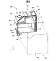
インクタンク43Aは、6つの面部61〜66を有する中空容器として構成されている(図6,図7)。第1面部61(図7)は下方を向く底面部を構成し、第2面部62(図6)は上方を向く上面部を構成する。第3面部63(図6)は、第1面部61と第2面部62とに交差し、タンクユニット40Aにおいて正面側を向く正面部を構成する。第4面部64(図7)は、第1面部61と第2面部62とに交差し、第3面部63とは反対の方向を向く背面部を構成する。第5面部65(図7)は、前記の4つの面部61〜64のそれぞれに交差し、第3面部63に正対したときに左側に位置する左側面部を構成する。第6面部66(図6)は、4つの面部61〜64のそれぞれに交差し、第3面部63に正対したときに、右側に位置する右側面部を構成する。
The
インク筒部46Aは、6つの面部81〜86を有する中空容器として構成されている(図9)。インク筒部46Aの第1面部81は下方を向く底面部を構成し、第2面部82は上方を向く上面部を構成する。第3面部83は、第1面部81と第2面部82とに交差し、タンクユニット40Aにおいて矢印Yの方向を向き、プリンター10の正面側を向く。第4面部84は、第1面部81と第2面部82とに交差し、第3面部83とは反対の方向を向く。第5面部85は、前記の4つの面部81〜84のそれぞれに交差し、第3面部83に正対したときに右側に位置する右側面部を構成する。第6面部86は、4つの面部81〜84のそれぞれに交差し、第3面部83に正対したときに、左側に位置する左側面部を構成する。インク筒部46Aにおいても、インクタンク43Aと同様に、隣り合う各面部の間に湾曲面を構成する面取り部などが介在していても良い。
The ink cylinder portion 46A is configured as a hollow container having six surface portions 81 to 86 (FIG. 9). The first surface portion 81 of the ink cylinder portion 46A constitutes a bottom surface portion facing downward, and the second surface portion 82 constitutes an upper surface portion facing upward. The third surface portion 83 intersects the first surface portion 81 and the second surface portion 82, faces the direction of arrow Y in the tank unit 40A, and faces the front side of the printer 10. The fourth surface portion 84 intersects the first surface portion 81 and the second surface portion 82 and faces the direction opposite to the third surface portion 83. The fifth surface 85 intersect to each of the four surface portions 81 to 84 constitute a right side portion located on the right side when faces the third surface portion 83. The sixth surface portion 86 intersects each of the four surface portions 81 to 84, when directly facing the third surface portion 83, constitutes a left side portion located on the left side. Also in the ink cylinder portion 46A, similarly to the
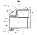
インク収容室90の下端よりも上端に近い上端側の部位には、大気導入部92が設けられている(図10)。大気導入部92は、インク収容室90に対して大気が流入可能なように、外部からインク収容室90に連通する部位である。本実施形態では、大気導入部92は、第4面部84において矢印Yの逆方向に突出する円筒状の部位として構成されており、インク収容室90に連通する貫通孔92hを有している。大気導入部92の先端部においては、大気開放口92oが外部に向かって開口している。なお、大気導入部76は、第4面部84に設けられていなくても良く、例えば、第2面部82において上方に突出するように設けられていても良い。
An air introduction portion 92 is provided in a portion on the upper end side closer to the upper end than the lower end of the ink storage chamber 90 (FIG. 10). The air introduction part 92 is a part that communicates with the ink storage chamber 90 from the outside so that air can flow into the ink storage chamber 90. In the present embodiment, the air introduction portion 92 is configured as a cylindrical portion that protrudes in the direction opposite to the arrow Y on the fourth surface portion 84, and has a through hole 92 h that communicates with the ink storage chamber 90. At the tip of the air introduction part 92, an air opening 92o is open to the outside. Note that the
第7実施形態のタンクユニット40Gでは、インクタンク43Fのインク供給部73と、それに対応するインク筒部46Gのインク流通部91とがチューブ47によって接続されている。当該インク筒部46Gのインク供給部98は、チューブ44を介して、印刷ヘッド部25に接続されている。このように、第7実施形態のタンクユニット40Gでは、インクタンク43Fを上流側とし、インク筒部46Gを下流側として、両者が直列に接続されている。このような接続構成を有している第7実施形態のタンクユニット40Gであっても、第1実施形態で説明したのと同様な種々の作用効果を奏することができる。タンクユニット40Gを備えるプリンターにおいても同様である。
In the tank unit 40G of the seventh embodiment, the
Claims (13)
前記液体を収容可能であるとともに、大気を導入可能である第1液体収容部と、
前記液体を収容可能であり、前記第1液体収容部から前記液体が流入可能なように、前記第1液体収容部に連通するとともに、大気を導入可能である第2液体収容部と、
前記第2液体収容部に収容されている前記液体を検出可能な検出部と、
を備え、
前記検出部が前記液体を検出する検出部位における前記第2液体収容部の水平断面の断面積は、前記検出部位の位置に対応する高さ位置における前記第1液体収容部の水平断面の断面積よりも小さい、液体供給装置。 A liquid supply device capable of supplying liquid to a liquid consumption device,
A first liquid storage unit capable of storing the liquid and capable of introducing air; and
A second liquid storage section that can store the liquid and communicates with the first liquid storage section so that the liquid can flow in from the first liquid storage section;
A detection unit capable of detecting the liquid stored in the second liquid storage unit;
With
The cross-sectional area of the horizontal cross section of the second liquid storage unit at the detection site where the detection unit detects the liquid is the cross-sectional area of the horizontal cross section of the first liquid storage unit at a height position corresponding to the position of the detection site. Smaller than the liquid supply device.
前記検出部位は、重力方向において、前記第2液体収容部の上端よりも下端に近い下端側に位置しており、
前記検出部は、前記検出部位における前記液体の有無を検出する、液体供給装置。 The liquid supply apparatus according to claim 1,
The detection site is located on the lower end side closer to the lower end than the upper end of the second liquid container in the direction of gravity,
The said detection part is a liquid supply apparatus which detects the presence or absence of the said liquid in the said detection part.
前記第2液体収容部は、ユーザーが外部から前記液体の液面の位置を視認可能な視認部を有する、液体供給装置。 The liquid supply device according to claim 1 or 2,
The liquid supply device, wherein the second liquid storage unit includes a visual recognition unit that allows a user to visually recognize the position of the liquid level from the outside.
前記第2液体収容部と前記第1液体収容部との間に、互いの間で前記大気を流通させる大気流通路が設けられている、液体供給装置。 The liquid supply device according to any one of claims 1 to 3,
A liquid supply apparatus, wherein an air flow passage is provided between the second liquid storage portion and the first liquid storage portion to circulate the air between each other.
前記第1液体収容部は、前記液体が収容される液体収容室と、前記液体収容室に連通し、前記大気が収容される大気収容室と、を有し、
前記大気流通路は、前記大気収容室に接続されている、液体供給装置。 The liquid supply device according to claim 4,
The first liquid storage unit includes a liquid storage chamber that stores the liquid, and an air storage chamber that communicates with the liquid storage chamber and stores the air.
The liquid supply apparatus, wherein the atmospheric flow passage is connected to the atmospheric chamber.
前記第2液体収容部は、前記液体を収容可能な液体収容室と、外部に向かって開口する大気開放口と、前記大気開放口から前記液体収容室に向かって延び、前記液体収容室に導入される前記大気が流通する大気連通路と、を備える、液体供給装置。 The liquid supply device according to any one of claims 1 to 3,
The second liquid storage unit is configured to receive a liquid, a liquid storage chamber capable of storing the liquid, an air opening opening that opens to the outside, and the liquid opening chamber that extends from the air opening to the liquid storage chamber. An air communication path through which the air flows.
前記第2液体収容部は、外部から液体を注入可能な注入口を有する液体注入部を備える、液体供給装置。 A liquid supply apparatus according to any one of claims 4 to 6 dependent on claim 3 or claim 3,
The second liquid storage unit is a liquid supply apparatus including a liquid injection unit having an injection port through which liquid can be injected from the outside.
前記第2液体収容部は、前記液体注入部の前記注入口を封止可能な封止部材を備える、液体供給装置。 The liquid supply device according to claim 7,
The liquid supply apparatus, wherein the second liquid storage unit includes a sealing member capable of sealing the injection port of the liquid injection unit.
複数の組の一対の前記第1液体収容部と前記第2液体収容部とを備え、
複数の前記第1液体収容部が、第1の方向に列状に配列されている第1液体収容部列と、複数の前記第2液体収容部が、前記第1の方向に交差する第2の方向に列状に配列されている第2液体収容部列と、が構成されている、液体供給装置。 The liquid supply device according to any one of claims 1 to 8,
A plurality of pairs of the first liquid storage portion and the second liquid storage portion;
A second liquid storage section row in which a plurality of the first liquid storage sections are arranged in a row in a first direction and a second liquid storage section that intersects the first direction. And a second liquid storage unit row arranged in a row in the direction of the liquid supply device.
前記第2液体収容部列は、前記第1液体収容部列に対して、前記第1の方向において、隣り合う位置に配置されており、
前記第2液体収容部列の前記第2の方向における幅は、前記第1液体収容部列の前記第2の方向における幅よりも小さい、液体供給装置。 The liquid supply device according to claim 9,
The second liquid storage portion row is disposed at a position adjacent to the first liquid storage portion row in the first direction,
It said second width in said second direction of the liquid containing portion row, the smaller than the first width in the second direction of the liquid storage portion rows, the liquid supply device.
前記検出部は、前記第2液体収容部の内部に配置される検出素子と、前記第2液体収容部の外部に配置され、前記検出素子との間で信号をやりとりする接続部と、を含み、
前記接続部は、前記第1液体収容部列と、前記第2液体収容部列と、の間に配置されている、液体供給装置。 The liquid supply apparatus according to claim 10, wherein
The detection unit includes a detection element arranged inside the second liquid storage unit, and a connection unit arranged outside the second liquid storage unit and exchanges signals with the detection element. ,
The connection part is a liquid supply apparatus, which is disposed between the first liquid storage part row and the second liquid storage part row.
請求項1から請求項11のいずれか一項に記載の液体供給装置と、
前記液体供給装置から供給される前記液体を消費する液体消費部と、
を備える、液体消費装置。 A liquid consuming device,
A liquid supply device according to any one of claims 1 to 11,
A liquid consumption unit for consuming the liquid supplied from the liquid supply device;
A liquid consuming device comprising:
前記第2液体収容部は、前記液体消費装置の正面側に配置されている、液体消費装置。 A liquid consuming device according to claim 12,
The second liquid container is a liquid consuming device arranged on the front side of the liquid consuming device.
Priority Applications (10)
| Application Number | Priority Date | Filing Date | Title |
|---|---|---|---|
| JP2015070897A JP6657583B2 (en) | 2015-03-31 | 2015-03-31 | Liquid supply device and liquid consumption device |
| TW105109911A TW201637885A (en) | 2015-03-31 | 2016-03-29 | Liquid supply device and liquid consuming device |
| US15/562,886 US10195860B2 (en) | 2015-03-31 | 2016-03-30 | Liquid supply apparatus and liquid consuming apparatus |
| CN201680017501.8A CN107405927A (en) | 2015-03-31 | 2016-03-30 | Fluid Supplying apparatus and liquid consuming device |
| BR112017020829-6A BR112017020829A2 (en) | 2015-03-31 | 2016-03-30 | liquid supply device and liquid consumption device |
| CN202010328227.4A CN111546777B (en) | 2015-03-31 | 2016-03-30 | Printer and liquid supply device |
| KR1020177027536A KR20170120177A (en) | 2015-03-31 | 2016-03-30 | Liquid supply device and liquid consumption device |
| PCT/JP2016/001845 WO2016157901A1 (en) | 2015-03-31 | 2016-03-30 | Liquid supply device and liquid consuming device |
| PH12017501709A PH12017501709A1 (en) | 2015-03-31 | 2017-09-18 | Liquid supply apparatus and liquid consuming apparatus |
| JP2020018557A JP6923020B2 (en) | 2015-03-31 | 2020-02-06 | printer |
Applications Claiming Priority (1)
| Application Number | Priority Date | Filing Date | Title |
|---|---|---|---|
| JP2015070897A JP6657583B2 (en) | 2015-03-31 | 2015-03-31 | Liquid supply device and liquid consumption device |
Related Child Applications (1)
| Application Number | Title | Priority Date | Filing Date |
|---|---|---|---|
| JP2020018557A Division JP6923020B2 (en) | 2015-03-31 | 2020-02-06 | printer |
Publications (3)
| Publication Number | Publication Date |
|---|---|
| JP2016190354A JP2016190354A (en) | 2016-11-10 |
| JP2016190354A5 true JP2016190354A5 (en) | 2018-04-19 |
| JP6657583B2 JP6657583B2 (en) | 2020-03-04 |
Family
ID=57004400
Family Applications (1)
| Application Number | Title | Priority Date | Filing Date |
|---|---|---|---|
| JP2015070897A Active JP6657583B2 (en) | 2015-03-31 | 2015-03-31 | Liquid supply device and liquid consumption device |
Country Status (8)
| Country | Link |
|---|---|
| US (1) | US10195860B2 (en) |
| JP (1) | JP6657583B2 (en) |
| KR (1) | KR20170120177A (en) |
| CN (2) | CN111546777B (en) |
| BR (1) | BR112017020829A2 (en) |
| PH (1) | PH12017501709A1 (en) |
| TW (1) | TW201637885A (en) |
| WO (1) | WO2016157901A1 (en) |
Families Citing this family (20)
| Publication number | Priority date | Publication date | Assignee | Title |
|---|---|---|---|---|
| JP6961946B2 (en) * | 2017-01-31 | 2021-11-05 | ブラザー工業株式会社 | Supply device |
| JP2018161874A (en) | 2017-03-27 | 2018-10-18 | ブラザー工業株式会社 | Liquid cartridge |
| JP6950228B2 (en) | 2017-03-27 | 2021-10-13 | ブラザー工業株式会社 | Liquid cartridges and systems |
| JP6825445B2 (en) * | 2017-03-27 | 2021-02-03 | セイコーエプソン株式会社 | Containment unit and method of controlling the amount of liquid in the accommodation unit |
| US10493765B2 (en) | 2017-03-27 | 2019-12-03 | Brother Kogyo Kabushiki Kaisha | Liquid cartridge capable of reducing leakage of liquid from liquid storage chamber |
| JP6942988B2 (en) | 2017-03-27 | 2021-09-29 | ブラザー工業株式会社 | Liquid cartridges and systems |
| JP7031132B2 (en) | 2017-03-27 | 2022-03-08 | ブラザー工業株式会社 | Liquid cartridges and systems |
| WO2019012786A1 (en) * | 2017-07-12 | 2019-01-17 | セイコーエプソン株式会社 | Liquid-holding container |
| EP3437877B1 (en) * | 2017-07-31 | 2021-03-17 | Brother Kogyo Kabushiki Kaisha | Liquid cartridge and system therefor |
| JP7077612B2 (en) * | 2017-12-27 | 2022-05-31 | ブラザー工業株式会社 | Liquid drainer |
| JP7035647B2 (en) * | 2018-03-12 | 2022-03-15 | ブラザー工業株式会社 | system |
| JP7063065B2 (en) * | 2018-03-30 | 2022-05-09 | ブラザー工業株式会社 | system |
| JP7164455B2 (en) * | 2019-01-31 | 2022-11-01 | 理想科学工業株式会社 | container |
| JP7236280B2 (en) * | 2019-01-31 | 2023-03-09 | 理想科学工業株式会社 | tank |
| JP7298173B2 (en) * | 2019-02-12 | 2023-06-27 | セイコーエプソン株式会社 | printer |
| JP7305973B2 (en) * | 2019-02-12 | 2023-07-11 | セイコーエプソン株式会社 | printer |
| JP7247624B2 (en) * | 2019-02-12 | 2023-03-29 | セイコーエプソン株式会社 | printer |
| JP7363333B2 (en) * | 2019-10-10 | 2023-10-18 | セイコーエプソン株式会社 | Liquid storage container and liquid injection device |
| JP2022179914A (en) * | 2021-05-24 | 2022-12-06 | セイコーエプソン株式会社 | Recording device and liquid storage body |
| JP2023083127A (en) * | 2021-12-03 | 2023-06-15 | ブラザー工業株式会社 | Tank unit, head system, ink supply system, printing system, and printing method |
Family Cites Families (34)
| Publication number | Priority date | Publication date | Assignee | Title |
|---|---|---|---|---|
| JPS5924676A (en) * | 1982-07-31 | 1984-02-08 | Sharp Corp | Apparatus for removing air bubble of ink jet printer |
| JPH07106637B2 (en) * | 1983-08-02 | 1995-11-15 | キヤノン株式会社 | Recording device |
| DE3428434C2 (en) * | 1983-08-02 | 1995-09-14 | Canon Kk | Printing device |
| JPS61195848A (en) * | 1985-02-25 | 1986-08-30 | Ricoh Co Ltd | Ink jet recorder |
| JPS62156963A (en) * | 1985-12-28 | 1987-07-11 | Canon Inc | Recorder |
| JPH05340791A (en) | 1992-06-11 | 1993-12-21 | Canon Inc | Liquid level detecting means and ink jet recorder |
| JPH08281966A (en) * | 1995-04-13 | 1996-10-29 | Matsushita Electric Ind Co Ltd | Ink jet recorder and residual ink detecting method |
| JPH09145451A (en) | 1995-11-16 | 1997-06-06 | Brother Ind Ltd | Residual quantity detecting device |
| JPH10230623A (en) * | 1997-02-21 | 1998-09-02 | Hitachi Koki Co Ltd | Method and apparatus for removing bubble from ink jet printer employing thermally fusible ink |
| JPH11192720A (en) * | 1998-01-05 | 1999-07-21 | Seiko Epson Corp | Ink jet recorder, ink filling method, and ink supplying method |
| US6293662B1 (en) * | 1998-01-19 | 2001-09-25 | Canon Kabushiki Kaisha | Ink tank coupling method, ink jet recording apparatus, and ink tank |
| DE29915256U1 (en) * | 1999-08-31 | 2000-03-09 | Sailer Johann | Device for measuring the liquid level |
| US6431672B1 (en) * | 2001-03-01 | 2002-08-13 | Hewlett-Packard Company | Ink container having dual capillary members with differing capillary pressures for precise ink level sensing |
| JP2004090432A (en) * | 2002-08-30 | 2004-03-25 | Seiko Epson Corp | Liquid injection device, tank for discharging liquid of liquid injection device, and liquid discharging method of liquid injection device |
| JP2005161637A (en) * | 2003-12-02 | 2005-06-23 | Canon Inc | Ink supply mechanism of inkjet recording apparatus, and head cartridge |
| US7210771B2 (en) * | 2004-01-08 | 2007-05-01 | Eastman Kodak Company | Ink delivery system with print cartridge, container and reservoir apparatus and method |
| JP4384067B2 (en) * | 2004-03-23 | 2009-12-16 | キヤノン株式会社 | Liquid ejecting apparatus and liquid processing method |
| JP2007160850A (en) * | 2005-12-16 | 2007-06-28 | Sony Corp | Liquid supply device |
| JP2007237552A (en) * | 2006-03-08 | 2007-09-20 | Fuji Xerox Co Ltd | Liquid droplet discharge unit, and droplet discharge apparatus |
| JP5014006B2 (en) * | 2006-07-19 | 2012-08-29 | キヤノン株式会社 | ink cartridge |
| CN101559674A (en) * | 2008-04-18 | 2009-10-21 | 株式会社御牧工程 | Ink replenisher and inkjet printer equipped with the ink replenisher |
| CN201317161Y (en) * | 2008-12-04 | 2009-09-30 | 珠海纳思达电子科技有限公司 | Ink box for ink-jet printer |
| JP5352902B2 (en) * | 2009-09-09 | 2013-11-27 | 株式会社ミマキエンジニアリング | Ink level monitoring method |
| CN202368067U (en) * | 2011-11-14 | 2012-08-08 | 常州纳捷机电科技有限公司 | Convenient ink box |
| JP5834951B2 (en) * | 2012-01-25 | 2015-12-24 | セイコーエプソン株式会社 | Liquid container and liquid consumption device |
| JP2013151100A (en) * | 2012-01-25 | 2013-08-08 | Seiko Epson Corp | Liquid supply system and liquid jet device |
| JP6115029B2 (en) * | 2012-05-31 | 2017-04-19 | セイコーエプソン株式会社 | Method for manufacturing liquid container |
| JP2014058087A (en) * | 2012-09-14 | 2014-04-03 | Seiko Epson Corp | Liquid storage body, liquid storage body unit, liquid consumption device, and manufacturing method of liquid storage body |
| JP6075097B2 (en) * | 2013-02-07 | 2017-02-08 | セイコーエプソン株式会社 | Liquid container, liquid supply system |
| JP6102596B2 (en) * | 2013-07-19 | 2017-03-29 | セイコーエプソン株式会社 | Ink tank unit, inkjet printer, ink tank |
| JP2014184594A (en) * | 2013-03-22 | 2014-10-02 | Seiko Epson Corp | Ink supply system |
| JP2014195974A (en) * | 2013-03-29 | 2014-10-16 | ブラザー工業株式会社 | Liquid storage device |
| JP2015044379A (en) * | 2013-08-29 | 2015-03-12 | キヤノン株式会社 | Liquid discharge device and control method of the same |
| JP6260212B2 (en) * | 2013-11-12 | 2018-01-17 | セイコーエプソン株式会社 | Recording device |
-
2015
- 2015-03-31 JP JP2015070897A patent/JP6657583B2/en active Active
-
2016
- 2016-03-29 TW TW105109911A patent/TW201637885A/en unknown
- 2016-03-30 CN CN202010328227.4A patent/CN111546777B/en active Active
- 2016-03-30 WO PCT/JP2016/001845 patent/WO2016157901A1/en active Application Filing
- 2016-03-30 BR BR112017020829-6A patent/BR112017020829A2/en not_active Application Discontinuation
- 2016-03-30 CN CN201680017501.8A patent/CN107405927A/en active Pending
- 2016-03-30 KR KR1020177027536A patent/KR20170120177A/en not_active Application Discontinuation
- 2016-03-30 US US15/562,886 patent/US10195860B2/en active Active
-
2017
- 2017-09-18 PH PH12017501709A patent/PH12017501709A1/en unknown
Similar Documents
| Publication | Publication Date | Title |
|---|---|---|
| JP2016190354A5 (en) | ||
| US8491108B2 (en) | Ink jet recording apparatus | |
| CN106626765A (en) | Printing apparatus and liquid storage member | |
| JP2014520689A5 (en) | ||
| JP5565329B2 (en) | Liquid container to be mounted on liquid ejecting apparatus | |
| JP2013212706A5 (en) | ||
| RU2016110794A (en) | LIQUID STORAGE CONTAINER AND LIQUID-JET BLOCK | |
| JP2017081084A5 (en) | ||
| JP6287510B2 (en) | Liquid consumption device | |
| JP2008000962A5 (en) | ||
| RU2015142056A (en) | LIQUID FEEDING DEVICE AND LIQUID CONTAINING ELEMENT | |
| JP2016168729A5 (en) | ||
| JP2009018566A (en) | Fluid supplying apparatus, fluid jet apparatus, and fluid supplying method | |
| JP2018008510A (en) | Liquid supply mechanism, liquid discharge device, and liquid supply method | |
| US11433677B2 (en) | Liquid storage device and liquid filling method | |
| JP2016168721A5 (en) | ||
| JP2018501491A5 (en) | ||
| CN203888377U (en) | Centralized ink supplying device with automatic heating function | |
| JP2014040110A5 (en) | ||
| EP2087999A3 (en) | Liquid ejecting head and liquid ejecting device | |
| JP2016175395A5 (en) | ||
| US9340028B2 (en) | Liquid storing device, liquid storing method and inkjet recording device | |
| JP2022043079A5 (en) | ||
| JP6987923B2 (en) | Liquid refill system | |
| US9033476B2 (en) | Protective cap |