JP2016177347A - Database system - Google Patents
Database system Download PDFInfo
- Publication number
- JP2016177347A JP2016177347A JP2015055069A JP2015055069A JP2016177347A JP 2016177347 A JP2016177347 A JP 2016177347A JP 2015055069 A JP2015055069 A JP 2015055069A JP 2015055069 A JP2015055069 A JP 2015055069A JP 2016177347 A JP2016177347 A JP 2016177347A
- Authority
- JP
- Japan
- Prior art keywords
- data
- value
- query
- value list
- column
- Prior art date
- Legal status (The legal status is an assumption and is not a legal conclusion. Google has not performed a legal analysis and makes no representation as to the accuracy of the status listed.)
- Pending
Links
Images


Classifications
-
- G—PHYSICS
- G06—COMPUTING; CALCULATING OR COUNTING
- G06F—ELECTRIC DIGITAL DATA PROCESSING
- G06F16/00—Information retrieval; Database structures therefor; File system structures therefor
- G06F16/20—Information retrieval; Database structures therefor; File system structures therefor of structured data, e.g. relational data
- G06F16/22—Indexing; Data structures therefor; Storage structures
- G06F16/221—Column-oriented storage; Management thereof
-
- G—PHYSICS
- G06—COMPUTING; CALCULATING OR COUNTING
- G06F—ELECTRIC DIGITAL DATA PROCESSING
- G06F16/00—Information retrieval; Database structures therefor; File system structures therefor
- G06F16/20—Information retrieval; Database structures therefor; File system structures therefor of structured data, e.g. relational data
- G06F16/24—Querying
- G06F16/248—Presentation of query results
-
- G—PHYSICS
- G06—COMPUTING; CALCULATING OR COUNTING
- G06F—ELECTRIC DIGITAL DATA PROCESSING
- G06F16/00—Information retrieval; Database structures therefor; File system structures therefor
- G06F16/20—Information retrieval; Database structures therefor; File system structures therefor of structured data, e.g. relational data
- G06F16/25—Integrating or interfacing systems involving database management systems
- G06F16/252—Integrating or interfacing systems involving database management systems between a Database Management System and a front-end application
Abstract
Description
本発明は、列指向のデータベースシステム、データベースサーバ、情報処理方法、プログラムに関する。 The present invention relates to a column-oriented database system, a database server, an information processing method, and a program.
表の1列1列を一つのかたまりとしてデータを格納する列指向データベースが知られている。列指向データベースでは、列方向にデータをまとめている。そのため、列指向データベースは集計などの処理を高速に行うことに優れており、大量データの一括更新を行うようなバッチ処理や大量データの集計や分析などを行う場合に活用されている。 2. Description of the Related Art A column-oriented database that stores data using one column and one column of a table as one group is known. In a column-oriented database, data is collected in the column direction. For this reason, the column-oriented database is excellent in performing processing such as summarization at high speed, and is used for batch processing that performs batch update of a large amount of data, and for summarization and analysis of a large amount of data.
また、列指向データベースの中にはFAST(Filter Array Structure)構造を持つものがあることが知られている。FAST構造は、データを順序、位置、値などに分解して管理しており、サーバ内の処理性能に優れている。 Further, it is known that some column-oriented databases have a FAST (Filter Array Structure) structure. The FAST structure manages data by decomposing it into an order, position, value, etc., and has excellent processing performance in the server.
FAST構造を有する列指向データベースについての技術としては、例えば、特許文献1が知られている。特許文献1には、テーブル抽出部と値リスト変換部とポインタ処理部と情報ブロック管理部とを備えたCPUが記載されている。特許文献1によると、情報ブロック管理部が取り出した情報ブロックの値リストをテーブル抽出部が参照して、共有化すべき値リストを抽出する。続いて、値リスト変換部が、項目値の変換が必要となる値リストに項目値を挿入する。その後、ポインタ処理部がポインタ値を変換するとともに、必要な他のポインタ配列を生成する。特許文献1によると、このような処理により、FAST構造で表された複数の表を結合することが出来る。
For example,
また、データベースにおいては、複数のデータノードにデータを分散して格納する分散ストレージシステムが知られている。分散ストレージシステムを利用とした技術としては、例えば、特許文献2がある。特許文献2には、論理的には同一であるが物理的には異なるデータ構造を有する少なくとも2つのデータノードを含む分散ストレージシステムが記載されている。特許文献2によると、このように構成することで、データの利用形態の特性が異なるアプリケーションなどに対しても迅速に応答することが可能となり、応答性能の低下などを回避することが可能となる。
In addition, as a database, a distributed storage system that stores data in a plurality of data nodes in a distributed manner is known. As a technique using a distributed storage system, for example, there is
しかしながら、特許文献1に記載のようなFAST構造を利用している場合、データの整合性を確保するために膨大な値リストを送信する必要がある場合があり、その結果、ネットワークトラフィックが増加してしまうことがある、という問題が生じていた。また、特許文献2でも、同様の問題が生じる可能性があった。
However, when the FAST structure as described in
この問題に対しては、FAST構造から行指向のデータ構造へ変換してからクライアントに送信することで不必要なデータの送信を防ぐ、という対処法が知られている。しかしながら、行指向のデータ構造に変換した場合、重複するデータを送ってしまう場合がある。このように、行指向のデータ構造へ変換したとしても、ネットワークトラフィックの増大を防ぐことが難しい場合があった。 To solve this problem, a countermeasure is known in which unnecessary data transmission is prevented by transmitting the data from the FAST structure to the row-oriented data structure and then transmitting it to the client. However, when converted to a row-oriented data structure, duplicate data may be sent. As described above, even if the data is converted into a row-oriented data structure, it may be difficult to prevent an increase in network traffic.
以上のように、列指向のデータベースにおいては、サーバ・クライアント間のネットワークトラフィックの増大を防ぐことが難しい、という問題が生じていた。 As described above, the column-oriented database has a problem that it is difficult to prevent an increase in network traffic between the server and the client.
そこで、本発明の目的は、列指向のデータベースにおいて、サーバ・クライアント間のネットワークトラフィックの増大を防ぐことが難しい、という問題を解決するデータベースシステムを提供することにある。 Therefore, an object of the present invention is to provide a database system that solves the problem that it is difficult to prevent an increase in network traffic between a server and a client in a column-oriented database.
かかる目的を達成するため本発明の一形態であるデータベースシステムは、
データベースサーバに対して問合せを実行するクライアントと、前記クライアントからの問合せに応じて、各問合せに対する回答をレコードで表し、当該レコードを含む問合せの実行結果の表を送信するデータベースサーバと、を有するデータベースシステムであって、
前記データベースサーバは、複数の列を有する前記実行結果の表を送信する際に、当該実行結果の表の列ごとに、当該列を表すことが出来る複数のデータ構造のうちのいずれかを用いて送信するデータ送信部を有する
という構成を採る。
In order to achieve such an object, a database system according to one aspect of the present invention provides:
A database that includes a client that executes a query to a database server, and a database server that represents a response to each query as a record and transmits a query execution result table including the record in response to the query from the client. A system,
When transmitting the execution result table having a plurality of columns, the database server uses, for each column of the execution result table, any one of a plurality of data structures that can represent the column. A configuration is adopted in which a data transmission unit for transmission is provided.
また、本発明の他の形態であるデータベースサーバは、
クライアントからの問合せに応じて、各問合せに対する回答をレコードで表し、当該レコードを含む問合せの実行結果の表を送信するデータベースサーバであって、
複数の列を有する前記実行結果の表を送信する際に、当該実行結果の表の列ごとに、当該列を表すことが出来る複数のデータ構造のうちのいずれかを用いて送信するデータ送信部を有する
という構成を採る。
Moreover, the database server which is the other form of this invention is
In response to a query from a client, a database server that represents a response to each query as a record and sends a query execution result table including the record,
When transmitting the execution result table having a plurality of columns, for each column of the execution result table, a data transmission unit that transmits using one of a plurality of data structures that can represent the column It has a configuration of having
また、本発明の他の形態である情報処理方法は、
クライアントからの問合せに応じて、各問合せに対する回答をレコードで表し、当該レコードを含み複数の列項目を有する問合せの実行結果の表を送信する際に、
前記実行結果の表の列ごとに、当該列を表すことが出来る複数のデータ構造のうちのいずれかを用いて送信する
という構成を採る。
In addition, an information processing method according to another aspect of the present invention includes:
In response to a query from the client, the response to each query is represented by a record, and when sending a query execution result table that includes the record and has multiple column items,
For each column of the execution result table, a configuration is adopted in which transmission is performed using any one of a plurality of data structures that can represent the column.
また、本発明の他の形態であるプログラムは、
クライアントからの問合せに応じて、各問合せに対する回答をレコードで表し、当該レコードを含む問合せの実行結果の表を送信するデータベースサーバに、
複数の列を有する前記実行結果の表を送信する際に、当該実行結果の表の列ごとに、当該列を表すことが出来る複数のデータ構造のうちのいずれかを用いて送信するデータ送信手段を実現させるためのプログラムである。
Moreover, the program which is the other form of this invention is:
In response to a query from the client, the response to each query is represented by a record, and a database server that sends a table of query execution results including the record is sent to the database server.
When transmitting the execution result table having a plurality of columns, for each column of the execution result table, data transmission means for transmitting using any of a plurality of data structures that can represent the column It is a program for realizing.
本発明は、以上のように構成されることにより、列指向のデータベースにおいて、サーバ・クライアント間のネットワークトラフィックの増大を防ぐことが難しい、という問題を解決するデータベースシステムを提供することが可能となる。 With the configuration as described above, the present invention can provide a database system that solves the problem that it is difficult to prevent an increase in network traffic between a server and a client in a column-oriented database. .
[第1の実施形態]
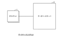
図1は、データベースシステム3の全体の構成を示すブロック図である。図2は、クライアント1とデータベースサーバ2との構成を示すブロック図である。図3は、FAST構造(順序集合2411と値番号/値リスト2412)を説明するための図である。図4は、結果セットデータ構造判定部25が値番号/値リスト2412のデータ構造を選択した場合に行う値番号の再計算処理を説明するための図である。図5は、結果セットデータ構造判定部25が値配列242のデータ構造を選択した場合に行う値配列242の作成処理を説明するための図である。図6は、データベースシステム3の全体的な動作を説明するためのフローチャートである。図7は、データベースサーバ2のデータ領域24に格納されている表の一例を示す図である。図8は、クエリの実行結果の表の一例を示す図である。図9、10は、結果セットデータ構造判定部25が行う転送コストの算出及びデータ構造の選択を説明するための図である。図11〜13は、結果セット取得部26が付加するヘッダ情報を説明するための図である。図14、15は、データ読取部121により行われるデータへのアクセスの仕方を説明するための図である。図16は、データベースシステム3がクエリの実行を行う際の動作の一例を示すシーケンス図である。図17は、クライアント1が結果セットの取得を行う際の動作の一例を示すシーケンス図である。図18は、データベースシステムがクエリを終了する際の動作の一例を示すシーケンス図である。
[First Embodiment]
FIG. 1 is a block diagram showing the overall configuration of the
図1で示すように、本発明の第1の実施形態では、クライアント1とデータベースサーバ2とを有するデータベースシステム3について説明する。クライアント1は、データベースサーバ2に対してクエリ(問合せ、処理要求)を送信する。データベースサーバ2は、クライアント1からクエリを受信すると、クエリを実行して、各問合せに対する回答をレコード(各行)で表すクエリの実行結果の表をFAST(Filter Array Structure)構造で生成する。そして、データベースサーバ2は、クエリの実行結果の表をクライアント1に対して送信する。後述するように、本実施形態におけるデータベースサーバ2は、複数の列を有するクエリの実行結果の表を送信する際に、実行結果の表の各列に対して複数のデータ構造における転送コストをそれぞれ算出する。そして、データベースサーバ2は、算出結果に基づいて列ごとにデータ構造を選択し、当該選択したデータ構造で列ごとにクエリの実行結果の表を送信する。
As shown in FIG. 1, in the first embodiment of the present invention, a
なお、クライアント1とデータベースサーバ2とは、例えばネットワークを介して接続されており、互いに通信可能なよう構成されている。また、データベースサーバ2と接続されたクライアント1の数は、1つでも構わないし、2つ以上の複数でも構わない。
The
クライアント1は、情報処理装置である。クライアント1は、図示しない演算装置(CPU:Central Processing Unit)と、記憶装置と、を有している。クライアント1は、記憶装置が有するプログラムをCPUが実行することで、後述するアプリケーション11とクライアントドライバ12とを実現するよう構成されている。
The
図2を参照すると、本実施形態におけるクライアント1は、アプリケーション11とクライアントドライバ12とを有している。
Referring to FIG. 2, the
アプリケーション11は、データベースサーバ2を利用する任意のアプリケーションである。アプリケーション11は、例えば、Java(登録商標)アプリケーションである。なお、アプリケーション11は、Javaアプリケーション以外であっても構わない。
The
クライアントドライバ12は、アプリケーション11とデータベースサーバ2との間のインターフェースである。クライアントドライバ12は、例えば、アプリケーション11からの要求に応じてデータベースサーバ2に対してクエリを送信したり、結果セット取得要求を送信したりする。また、クライアントドライバ12は、例えば、データベースサーバ2からクエリの結果の表を受信して、アプリケーション11に渡す。このように、クライアントドライバ12は、アプリケーション11がデータベースサーバ2を利用する際に利用される。クライアントドライバ12は、例えば、JDBC/ODBC(Open Database Connectivity)ブリッジドライバである。なお、クライアントドライバ12は、JDBC/ODBC以外のドライバであっても構わない。
The
図2で示すように、クライアントドライバ12は、データ読取部121とデータ領域122とを有している。
As shown in FIG. 2, the
データ読取部121は、データベースサーバ2から、クエリの実行結果の表を列ごとに受信する。例えば、データ受取部121は、データベースサーバ2からTCP/IP(Transmission Control Protocol/Internet Protocol)で転送されたデータを受信する。すると、データ受取部121は、当該受信したデータのヘッダ情報を参照して、受信したデータのデータ構造を識別する。そして、データ受取部121は、受信したデータをデータ領域122(の後述する結果セット格納領域1221)に格納する。
The
データ領域122は、半導体メモリなどの記憶装置である。データ領域122には、結果セット格納領域1221が設けられている。上記のように、結果セット格納領域1221には、データ読取部121がデータベースサーバ2から受信したデータが記憶される。結果セット格納領域1221は、例えば、クライアントドライバ12により問合せ(クエリ)ごとに生成され、クライアントドライバ12により問合せの終了と同時に破棄される。
The
データベースサーバ2は、情報処理装置である。データベースサーバ2は、図示しない演算装置(CPU)と、記憶装置と、を有している。データベースサーバ2は、記憶装置が有するプログラムをCPUが実行することで、後述する各機能(各部)を実現するよう構成されている。
The
図2を参照すると、データベースサーバ2は、クエリ解析部21と、実行計画部22と、クエリ実行部23と、データ領域24と、結果セットデータ構造判定部25と、結果セット取得部26と、を有している。
Referring to FIG. 2, the
クエリ解析部21は、クライアントドライバ12から送信されたクエリを構文解析する。つまり、クエリ解析部21は、クライアントドライバ12からクエリを受信する。そして、クエリ解析部21は、受信したクエリの構文解析を実行する。その後、クエリ解析部21は、解析結果を実行計画部22へ送信する。
The
実行計画部22は、クエリ解析部21が構文解析したクエリをどのような順序、方法で行えば効率的であるかを判定し、その実行計画を作成する。そして、実行計画部22は、作成した実行計画をクエリ実行部23に送信する。
The
クエリ実行部23は、実行計画部22で作成した実行計画に従って、データ領域24に対してデータ操作を行う。クエリ実行部23は、クエリの実行結果の表をデータ領域24に記憶することになる。
The
データ領域24は、半導体メモリやディスク装置などの記憶装置である。データ領域24には、データベースサーバ2のデータベースに登録されている表や、データベースサーバ2に対する問合せの結果(クエリ実行部23によるクエリの実行結果の表)が、表データ241として格納されている。
The
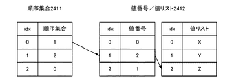
表データ241は、順序集合2411と複数の値番号/値リスト2412とから構成されている。このように、本実施形態におけるデータベースサーバ2は、表データをFAST構造で保管している。
The
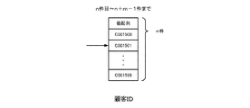
順序集合2411は、値番号/値リスト2412のうちの参照する値番号の位置を示している。例えば、図3で示す順序集合2411のうちの添え字(idx)「0」の順序集合「1」は、値番号/値リスト2412のうちの添え字「1」を参照することを示している。つまり、行番号(順序集合の添え字)に対応する順序集合2411の要素は、値番号の添え字に該当することになる。
The ordered set 2411 indicates the position of the reference value number in the value number /
値番号/値リスト2412は、データを値の一覧である値リストと前記値リストのうちの該当する位置を示す値番号との組み合わせで表現している。例えば、図3で示す値番号/値リスト2412のうちの添え字「1」の値番号「2」は、値番号/値リスト2412のうちの値リストの添え字「2」を参照する(値リスト=Z)ことを示している。このように、値番号の要素は値リストの添え字を示している。
The value number /
なお、図2では1つの順序集合2411を示したが、順序集合2411は複数あっても構わない。
Although one ordered set 2411 is shown in FIG. 2, a plurality of ordered
また、データ領域24には、値配列242を格納することが出来る。値配列242は、行番号に対応する値の配列で構成されるデータである。値配列242は、結果セットデータ構造判定部25により順序集合2411と値番号/値リスト2412から生成される。値配列242の詳細については後述する。
Further, a
結果セットデータ構造判定部25は、結果セット(クエリ実行部23により実行されたクエリの実行結果の表)の各列に対して、複数のデータ構造のそれぞれを用いた場合のデータ転送量を示す転送コストをそれぞれ算出する。そして、結果セットデータ構造判定部25は、算出した転送コストに基づいて、結果セットの各列に対してどのデータ構造で転送するかをそれぞれ判定する。
The result set data
具体的には、結果セットデータ構造判定部25は、結果セットの各列に対して、値番号/値リスト2412及び値配列242の総バイト数を見積もり、その値を転送コストとする。つまり、結果セットデータ構造判定部25は、データ構造として値番号/値リスト2412を用いた場合の転送コストと、データ構造として値配列242を用いた場合の転送コストと、を算出する。そして、結果セットデータ構造判定部25は、転送コストの少ない方のデータ構造を選択する。
Specifically, the result set data
また、結果セットデータ構造判定部25は、転送する際に用いるデータ構造を選択すると、当該選択したデータ構造に応じた処理を行う。
When the result set data
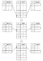
例えば、結果セットデータ構造判定部25は、値番号/値リスト2412を選択した場合、値番号の添え字(idx)を行番号に対応させる処理を行う。つまり、結果セットデータ構造判定部25は、図4で示すように、順序集合2411の要素を添え字としたときの値番号の要素を、新しい値番号(新値番号)の要素となるように、再計算する。例えば、図4を参照すると、添え字「0」の順序集合2411の要素「5」を添え字としたときの値番号の要素は「1」である。そこで、結果セットデータ構造判定部25は、添え字「0」の新値番号の要素を「1」に再計算する。このような処理を繰り返して、結果セットデータ構造判定部25は、値番号の添え字を行番号に対応させる。
For example, when the value set /
このように、結果セットデータ構造判定部25は、値番号/値リスト2412を選択した場合、値番号の添え字(idx)を行番号に対応させる処理を行う。このような処理を行うことで、転送する結果セットに順序集合2411を含める必要がなくなることになる。
As described above, when the value set /
また、結果セットデータ構造判定部25は、値配列242を選択した場合、対応する値番号/値リスト2412に基づいて、値配列242を作成する。例えば、図5を参照すると、結果セットデータ構造判定部25は、行番号に対応する順序集合2411の要素を値番号の添え字としたときの値番号の要素を求める。次に、求めた値番号を値リストの添え字としたときの値リストの要素を求める。ここで、値リストの各要素は実際のデータを意味している。そのため、結果セットデータ構造判定部25は、上記求めた値リストの要素を値配列242に追加していくことで、値配列242を作成する。
When the value set 242 is selected, the result set data
このように、結果セットデータ構造判定部25は、値配列242を選択した場合、行番号が添え字に対応するように値リストの各要素を追加することで、値配列242を作成する。
As described above, when the
結果セット取得部26は、クライアントドライバ12から結果セット取得要求を受け付ける。また、結果セット取得部26は、クライアントドライバ12から受け付けた結果セット取得要求に応じて、クライアントドライバ12に対して結果セットを転送する。
The result set
具体的には、結果セット取得部26は、結果セット取得要求に応じて、結果セットを列ごとに送信する。また、結果セット取得部26は、結果セットを列ごとに送信する際に、結果セットデータ構造判定部25が選択したデータ構造の識別情報を含むヘッダ情報を付加する。
Specifically, the result set
以上が、本実施形態におけるデータベースシステム3の構成についての説明である。次に、上記構成のデータベースシステム3が行う処理について具体例を挙げて説明する。
The above is the description of the configuration of the
図6で示すように、データベースシステム3の処理は、大きく、クエリの実行(ステップS001)、結果セットの取得(ステップS002)、クエリの終了(ステップS003)の3つの部分に分けることが出来る。以下、各部分の処理について説明する。
As shown in FIG. 6, the processing of the
まず、クエリの実行について説明する。この処理は、一般的なリレーショナルデータベースシステムと同様の処理となる。 First, query execution will be described. This process is the same as a general relational database system.
つまり、クライアントドライバ12が送信したクエリをクエリ解析部21が受信すると、クエリ解析部21は、受信したクエリの構文解析を実行する。その後、クエリ解析部21は、解析結果を実行計画部22へ送信する。続いて、実行計画部22は、クエリ解析部21が構文解析したクエリをどのような順序、方法で行えば効率的であるかを判定し、その実行計画を作成する。そして、実行計画部22は、作成した実行計画をクエリ実行部23に送信する。その後、クエリ実行部23は、実行計画部22で作成した実行計画に従ってクエリを実行する。これにより、クエリ実行部23は、クエリに対する実行結果の表を作成してデータ領域24の表データ241に格納する。なお、クエリ実行部23が作成する実行結果の表は、FAST構造である。
That is, when the
具体的に、例えば、データベースサーバ2の表データ241に図7で示す「顧客表」が格納されているとする。つまり、図7で示すように、顧客ID、姓、名、都道府県、登録日、更新日、などの列を有する表が100万件登録されていたとする。そして、この時に、下記式で示すクエリを実行したとする。
SELECT 顧客ID, 都道府県 FROM 顧客表 WHERE 登録日<’2009-01-01’;
Specifically, for example, it is assumed that the “customer table” shown in FIG. 7 is stored in the
SELECT customer ID, prefecture FROM customer table WHERE registration date <'2009-01-01';
その結果、クエリ実行部23は、例えば、図8で示すような実行結果の表をデータ領域24の表データ241にFAST構造で格納する。つまり、例えば、「顧客表」に登録日が2009年1月1日よりも前のデータが5000件ある場合、クエリ実行部23は、0から4999までを示す順序集合を格納する。この際、顧客ID列と、都道府県列とは、元の表のままであるため、元の顧客表のデータを参照することになる。
As a result, the
次に、結果セットの取得について説明する。 Next, acquisition of a result set will be described.
結果セット取得部26がクライアントドライバ12から結果セット取得要求を受信すると、結果セット取得部26は、クライアントドライバ12から受け付けたクエリに対する実行結果の表を取得する。
When the result set
結果セットデータ構造判定部25は、結果セット取得部26が取得した実行結果の表の各列に対して、値番号/値リスト2412の転送コストと、値配列242の転送コストと、の算出を行う。そして、結果セットデータ構造判定部25は、転送コストが小さいデータ構造を選択して、当該選択したデータ構造に応じた処理を行う。
The result set data
例えば、結果セットデータ構造判定部25は、下記式を用いて値番号/値リスト2412の転送コストと、値配列242の転送コストと、を算出する。
[値番号/値リストのデータ構造の転送コスト]
値番号の型のバイト数×順序集合の要素数+値リストの総バイト数
[値配列のデータ構造の転送コスト]
順序集合の要素数×値リストの総バイト数/値リストの要素数
For example, the result set data
[Transfer cost of value number / value list data structure]
Number of bytes of value number type x number of elements in ordered set + total number of bytes in value list [transfer cost of data structure of value array]
Number of elements in ordered set x total number of bytes in value list / number of elements in value list
そして、結果セットデータ構造判定部25は、転送コストが小さいデータ構造を選択して、選択したデータ構造に応じた処理を行う。
Then, the result set data
例えば、値番号/値リスト2412を選択した場合、結果セットデータ構造判定部25は、値番号の添え字(idx)を行番号に対応させる処理を行う。つまり、結果セットデータ構造判定部25は、図4で示すように、順序集合2411の要素を添え字としたときの値番号の要素を、新しい値番号(新値番号)の要素となるように、再計算する。また、値配列242を選択した場合、結果セットデータ構造判定部25は、対応する値番号/値リスト2412に基づいて、値配列242を作成する。つまり、結果セットデータ構造判定部25は、図5で示すように、行番号が添え字に対応するように値リストの各要素を追加することで、値配列242を作成する。
For example, when the value number /
このようにして、結果セットデータ構造判定部25は、転送コストが小さいデータ構造を選択するとともに所定の処理を行う。
In this way, the result set data
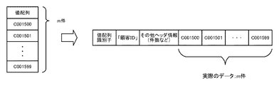
そして、結果セット取得部26は、値番号/値リスト2412として選択された列の値リストをクライアントドライバ12に送信する。この際、結果セット取得部26は、転送するデータが値リストであるという値リスト識別子及び参照元の表の値リストが一意に識別できる値リストIDをヘッダ情報として付加してクライアントドライバ12に値リストを転送する(図11参照)。
Then, the result set
その後、クライアントドライバ12のデータ読取部121は、データベースサーバ2から転送されたデータのヘッダ情報を読み取り、値リストと識別したものをデータ領域122の結果セット格納領域1221に格納する。
Thereafter, the
上記処理を、実行結果の表の一例として図8で示す実行結果の表がある場合について、より具体的に説明する。この場合、結果セットデータ構造判定部25は、顧客IDの列に対して、例えば下記のような転送コストの算出を行う(図9参照)。
[値番号/値リストのデータ構造の転送コスト]
値番号の型のバイト数×順序集合の要素数+値リストの総バイト数
=5000×4+800万=802万
[値配列のデータ構造の転送コスト]
順序集合の要素数×値リストの総バイト数/値リストの要素数
=5000×800万/100万=4万
The above process will be described more specifically in the case where there is an execution result table shown in FIG. 8 as an example of the execution result table. In this case, the result set data
[Transfer cost of value number / value list data structure]
Number of bytes of value number type × number of elements in ordered set + total number of bytes in value list = 5000 × 4 + 8 million = 802,000 [transfer cost of data structure of value array]
Number of elements in ordered set × total number of bytes in value list / number of elements in value list = 5000 × 8 million / 1 million = 40,000
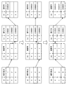
上記転送コストの算出結果からすると、値配列242のデータ構造の転送コストの方が値番号/値リスト2412のデータ構造の転送コストよりも転送コストが小さい。そのため、結果セットデータ構造判定部25は、図9で示すように、値配列242のデータ構造を選択して、値番号/値リスト2412に基づいて値配列242にデータ構造の変換を行う。そして、結果セットデータ構造判定部25は、変換した値配列242をデータ領域242に格納する。
From the calculation result of the transfer cost, the transfer cost of the data structure of the
一方、図8で示す実行結果の表の場合、結果セットデータ構造判定部25は、都道府県の列に対して、例えば下記のような転送コストの算出を行う(図10参照)。
[値番号/値リストのデータ構造の転送コスト]
値番号の型のバイト数×順序集合の要素数+値リストの総バイト数
=5000×1+337=約5000
[値配列のデータ構造の転送コスト]
順序集合の要素数×値リストの総バイト数/値リストの要素数
=5000×337/47=約3.6万
On the other hand, in the case of the execution result table shown in FIG. 8, the result set data
[Transfer cost of value number / value list data structure]
Number of bytes of value number type × number of elements in ordered set + total number of bytes in value list = 5000 × 1 + 337 = approximately 5000
[Transfer cost of data structure of value array]
Number of elements in ordered set × total number of bytes in value list / number of elements in value list = 5000 × 337/47 = about 36,000
この場合、値番号/値リスト2412のデータ構造の転送コストの方が値配列242のデータ構造の転送コストよりも転送コストが小さい。そのため、結果セットデータ構造判定部25は、図10で示すように、値番号/値リスト2412のデータ構造を選択して、値番号の再計算(新値番号の算出)を行う。
In this case, the transfer cost of the data structure of the value number /
そして、結果セットデータ構造判定部25による再計算の終了後、結果セット取得部26は、図11で示すように、値リストにヘッダ情報を付加してクライアントドライバ12に送信する。つまり、結果セット取得部26は、転送するデータが値リストであるという値リスト識別子及び参照元の表の値リストが一意に識別できる値リストIDをヘッダ情報として付加してクライアントドライバ12に値リストを転送する。
After the recalculation by the result set data
その後、クライアントドライバ12のデータ読取部121は、受け取ったデータのヘッダ情報から都道府県の列の値リストが転送されたことを確認する。そして、データ読取部121は、都道府県の列の値リストを結果セット格納領域1221に格納する。
Thereafter, the
上記のようにして値リストの転送が終わった後、実際にデータを取得するフェーズに入る。つまり、クライアントドライバ12は、任意の数であるnの値を動かしながら、n件目のデータをデータベースサーバ2から取得する。言い換えると、結果セット取得部26は、クライアントドライバ12からの要求に応じて、値配列242又は値番号/値リスト2412の値番号の要素の転送を行う。
After the transfer of the value list as described above, a phase for actually acquiring data is entered. That is, the
例えば、クライアントドライバ12は、データベースサーバ2に対して、結果セットのn件目からm件分のデータを要求したとする。
For example, it is assumed that the
このとき、値配列242を選択した列に対しては、結果セット取得部26は、値配列242のn番目からn+m−1番目までの配列データをクライアントドライバ12に送信する。また、この際、結果セット取得部26は、図12で示すように、値配列であることを示す識別子である値配列識別子を含んだヘッダ情報を付加して、クライアントドライバ12に対して、値配列242のn番目からn+m−1番目までの配列データを転送する。
At this time, for the column for which the
一方、値番号/値リスト2412を選択した列の場合、既に値リストは転送済みである。そのため、結果セット取得部26は、値番号のn番目からn+m−1番目までの要素をクライアントドライバ12に転送する。また、この際、結果セット取得部26は、図13で示すように、値番号であることを示す識別子である値番号識別子と、参照している値リストのID(値リストを送信する際にヘッダに付加した値リストID)と、を含んだヘッダ情報を付加して、クライアントドライバ12に対して、値番号のn番目からn+m−1番目までの要素を転送する。
On the other hand, in the case of the column in which the value number /
データ読取部121は、受け取ったデータのヘッダ情報を参照して、値番号と値配列242のどちらが転送されたのかを判断する。そして、データ読取部121は、受け取ったデータを結果セット格納領域1221に格納する。
The
このような一連の処理において、クライアントドライバ12は、nもしくはmの値を変えることで、必要な行番号のデータを取得することになる。
In such a series of processing, the
図8に示す例の場合では、データ読取部121は、受け取ったデータのヘッダ情報から、顧客IDの列のデータ構造が値配列242であることを識別することが出来る。また、データ読取部121は、データのヘッダ情報から、都道府県の列のデータ構造が値番号/値リスト2412であることを識別することが出来る。
In the case of the example illustrated in FIG. 8, the
また、値配列242のデータ構造を有する顧客IDの列にアクセスする際には、図14に示すように、データ読取部121は、受け取った値配列242にそのままアクセスすればよいことになる。また、値番号/値リスト2412のデータ構造を有する都道府県の列にアクセスする際には、データ読取部121は、受け取った値番号が利用している値リストIDと同じIDをもつ値リストを結果セット格納領域1221から取得する。そして、データ読取部121は、n番目からn+m−1番目だけ受け取った値番号(新値番号)を値リストの添え字として、図15で示すように、値リストにアクセスすることができる。
Further, when accessing the customer ID column having the data structure of the
次に、クエリの終了について説明する。 Next, the end of the query will be described.
クライアントドライバ12からクエリの終了を指示されると、データベースサーバ2の結果セット取得部26は、再計算された値番号(新値番号)、値配列242、実行結果の表を削除する。また、クライアント1のクライアントドライバ12は、結果セット格納領域1221に格納された値番号、値リスト、値配列242を削除する。
When instructed by the
このように、クエリの終了とともに、クエリの実行により作成された各種データは削除されることになる。 As described above, the various data created by executing the query are deleted as the query ends.
次に、図16乃至図18を参照して、データベースシステム3の動作について説明する。
Next, the operation of the
まず、図16を参照して、クエリの実行を行う際のデータベースシステム3の動作について説明する。
First, the operation of the
図16を参照すると、クライアントドライバ12は、アプリケーション11からの要求に応じて、データベースサーバ2に対してクエリを送信する(ステップS101)。
Referring to FIG. 16, the
クライアントドライバ12が送信したクエリをクエリ解析部21が受信する。すると、クエリ解析部21は、受信したクエリの構文解析を実行する(ステップS201)。その後、クエリ解析部21は、解析結果を実行計画部22へ送信する。
The
続いて、実行計画部22は、クエリ解析部21が構文解析したクエリをどのような順序、方法で行えば効率的であるかを判定し、その実行計画を作成する(ステップS202)。そして、実行計画部22は、作成した実行計画をクエリ実行部23に送信する。
Subsequently, the
その後、クエリ実行部23は、実行計画部22で作成した実行計画に従ってクエリを実行する(ステップS203)。これにより、クエリ実行部23は、クエリに対する実行結果の表を作成して、当該作成した実行結果の表をデータ領域24の表データ241に格納する(ステップS204)。なお、クエリ実行部23が作成する実行結果の表は、FAST構造である。
Thereafter, the
データベースシステム3は、例えば上記動作によりクエリの実行を行う。次に、図17を参照して、結果セットの取得を行う際のデータベースシステム3の動作について説明する。
The
図17を参照すると、クライアントドライバ12は、アプリケーション11からの要求に応じて、データベースサーバ2の結果セット取得部26に対して結果セット取得要求を送信する(ステップS102)。
Referring to FIG. 17, the
クライアントドライバ12から結果セット取得要求を受信すると、結果セット取得部26は、データ領域24を参照してクライアントドライバ12から受け付けたクエリに対する実行結果の表を取得する(ステップS301)。
When the result set acquisition request is received from the
続いて、結果セットデータ構造判定部25は、結果セット取得部26が取得した実行結果の表の各列に対して、値番号/値リスト2412の転送コストと、値配列242の転送コストと、の算出を行う。そして、結果セットデータ構造判定部25は、転送コストが小さいデータ構造を選択する(ステップS401)。その後、結果セットデータ構造判定部25は、選択したデータ構造に応じた処理を行う(ステップS402)。
Subsequently, the result set data
具体的には、結果セットデータ構造判定部25は、値番号/値リスト2412を選択した場合、値番号の添え字(idx)を行番号に対応させる処理を行う。つまり、結果セットデータ構造判定部25は、図4で示すように、順序集合2411の要素を添え字としたときの値番号の要素を、新しい値番号(新値番号)の要素となるように、再計算する。また、値配列242を選択した場合、結果セットデータ構造判定部25は、対応する値番号/値リスト2412に基づいて、値配列242を作成する。つまり、結果セットデータ構造判定部25は、図5で示すように、行番号が添え字に対応するように値リストの各要素を追加することで、値配列242を作成する。
Specifically, when the value set /
そして、結果セット取得部26は、値番号/値リスト2412として選択された列の値リストをクライアントドライバ12に送信する(ステップS302)。この際、結果セット取得部26は、転送するデータが値リストであるという値リスト識別子及び参照元の表の値リストが一意に識別できる値リストIDをヘッダ情報として付加してクライアントドライバ12に値リストを転送する。
Then, the result set
その後、クライアントドライバ12のデータ読取部121は、データベースサーバ2から転送されたデータのヘッダ情報を読み取り、値リストと識別したものをデータ領域122の結果セット格納領域1221に格納する(ステップS103)。
Thereafter, the
上記動作により値リストが転送されると、クライアントドライバ12は、データベースサーバ2に対して、結果セットのn件目からm件分のデータを要求する(ステップS104)。つまり、クライアントドライバ12は、実際のデータの取得を要求する。
When the value list is transferred by the above operation, the
クライアントドライバ12からデータの要求を受けると、結果セット取得部26は、当該要求に応じたデータをデータ領域24から取得して(ステップS303)、転送する(ステップS304)。
When receiving a data request from the
結果セット取得部26が行うこの動作は、対象の列のデータ構造に応じて行われることになる。つまり、結果セット取得部26は、値配列242を選択した列に対して、値配列242のn番目からn+m−1番目までの配列データをクライアントドライバ12に送信する。一方、値番号/値リスト2412を選択した列の場合、既に値リストは転送済みであるため、結果セット取得部26は、値番号のn番目からn+m−1番目までの要素をクライアントドライバ12に転送する。
This operation performed by the result set
その後、データ読取部121は、受け取ったデータのヘッダ情報を参照して、値番号と値配列242のどちらが転送されたのかを判断する。そして、データ読取部121は、受け取ったデータを結果セット格納領域1221に格納する(ステップS105)。
Thereafter, the
データベースシステム3は、例えば上記動作により結果セットの取得を行う。次に、図18を参照して、クエリを終了する際のデータベースシステム3の動作について説明する。
The
図18を参照すると、クライアントドライバ12は、アプリケーション11からの要求に応じて、クエリの終了の指示をデータベースサーバ2の結果セット取得26に対して送信する(ステップS106)。
Referring to FIG. 18, the
上記指示を受信すると、結果セット取得部26は、データ領域24に格納された、再計算された値番号である新値番号と、値配列242と、を削除する(ステップS305)。また、結果セット取得部26は、データ領域24から実行結果の表(表データ241)を削除する(ステップS306)。
When the instruction is received, the result set
また、クライアントドライバ12は、データ領域122の結果セット格納領域1221に格納された値番号、値リスト、値配列を削除する(ステップS107)。
Further, the
データベースシステム3は、例えば上記動作によりクエリを終了する。
The
このように、本実施形態におけるデータベースサーバ2は、結果セットデータ構造判定部25を有している。このような構成により、結果セットデータ構造判定部25は、結果セット(クエリ実行部23により実行されたクエリの実行結果の表)の各列に対して、値番号/値リスト2412のデータ構造を用いた場合と値配列242のデータ構造を用いた場合との転送コストを算出することが出来る。また、結果セットデータ構造判定部25は、転送コストの算出結果に基づいて、列ごとに転送する際のデータ構造を選択することが出来る。その結果、データベースサーバ2は、列ごとにデータ転送量の少ないデータ構造を選択してデータを転送することが可能となる。これにより、データベースサーバ2は、サーバ・クライアント間のネットワークトラフィックの増大を抑制することが可能となる。
As described above, the
[第2の実施形態]
本発明の第2の実施形態では、接続単位で値リストを再利用するデータベースシステム5について説明する。図19で示すように、1回の接続で複数の問合せがある場合などにおいて、異なる問い合わせで同一の値リストを参照することがある。例えば、図19の場合では、問合せ1と問合せ2とで、どちらも同一の表の都道府県の列の値リストを参照している。このような場合には、クライアントに対象となる値リストを記憶させておくことで、後の問合せに対する結果を送信する際に再度データベースサーバ2から値リストを転送する必要がなくなるものと考えられる。そこで、本実施形態においては、重複して値リストを送信することを防ぐことが出来るよう構成された、データベースシステム5について説明する。なお、以下においては、第1の実施形態で説明した構成と同様の構成については、同じ符号を付すものとする。
[Second Embodiment]
In the second embodiment of the present invention, a
図20を参照すると、本実施形態におけるデータベースシステム5は、クライアント4と、データベースサーバ2と、を有している。本実施形態におけるデータベースシステム5は、第1の実施形態で説明したデータベースシステム3とほぼ同様の構成を有している。
Referring to FIG. 20, the
つまり、データベースサーバ2は、クエリ解析部21と実行計画部22と、クエリ実行部23と、データ領域24と、結果セットデータ構造判定部25と、結果セット取得部26と、を有している。また、クライアント4は、アプリケーション11とデータ読取部121と、データ領域122とを有しており、データ領域122は、結果セット格納領域1221を有している。
That is, the
さらに、本実施形態におけるクライアント4は、値リスト一時記憶領域4222を有している。以下においては、データベースシステム5の特徴的な構成について説明する。
Furthermore, the
値リスト一時記憶領域4222は、データベースサーバ2の結果セット取得部26から転送された値リストのうち、データベースサーバ2が保有する既存の表から参照されているものを格納する領域である。つまり、値リスト一時記憶領域4222には、データベースサーバ2から転送された値リストのうち、クエリに応じた処理の途中で生成された値リストでなく既存の表を参照している値リストが格納されることになる。
The value list
値リスト一時記憶領域4222に格納された内容は、結果セット格納領域1221のデータが破棄されても影響を受けないよう構成されている。つまり、値リスト一時記憶領域4222に格納された内容は、クエリが終了するごとに破棄されないことになる。値リスト一時記憶領域4222に格納された内容は、例えば、クライアント4とデータベースサーバ2との接続が切れた時に、クライアントドライバ12により削除される。
The contents stored in the value list
なお、値リスト一時記憶領域4222が値リストを格納するか否か(値リストが既存の表から参照されているものであるか否か)は、例えば、結果セット取得部26が値リストを送信する際に付加するヘッダ情報を参照して、クライアントドライバ12により確認されることになる。
Whether or not the value list
本実施形態におけるクライアントドライバ12は、結果セット取得部26から対象の列の値リストが既に送信されているか否かの確認を受け取る。例えば、クライアントドライバ12は、結果セット取得部26から対象の列の値リストの値リストIDを受け取る。すると、クライアントドライバ12は、値リスト一時記憶領域4222を参照して、対象の列の値リストが値リスト一時記憶領域4222に記憶されているか否かを確認する。つまり、クライアントドライバ12は、結果セット取得部26から取得した値リストIDと等しいIDをもつ値リストが値リスト一時記憶領域4222に格納されているかを調べる。そして、クライアントドライバ12は、確認結果を結果セット取得部26に送信する。
The
また、クライアントドライバ12は、結果セット取得部26から値リストを受け取った場合、値リストのヘッダ情報を参照して当該受け取った値リストを結果セット格納領域1221に格納するか、値リスト一時記憶領域4222に格納するかを決定する。例えば、クライアントドライバ12は、値リストが既存の表を参照しているものの場合、当該値リストを値リスト一時記憶領域4222に格納する。一方、クライアントドライバ12は、値リストが処理の途中で生成されたものの場合、当該値リストを結果セット格納領域1221に格納する。
When the
本実施形態における結果セットデータ構造判定部25は、クライアントドライバ12に既に転送されている値リストを加味した上で、結果セットの各列に対して値番号/値リスト2412と値配列242を用いた場合の転送コストをそれぞれ算出する。そして、結果セットデータ構造判定部25は、結果セットの各列に対してどのデータ構造で転送するかを判定する。
The result set data
例えば、結果セットデータ構造判定部25は、クライアントドライバ12から受け取った値リストIDの確認結果により対象の列の値リストが既にクライアントドライバ12に転送されていると判断した場合、値番号/値リスト2412のデータ構造を選択する。そして、結果セットデータ構造判定部25は、値番号の添え字(idx)を行番号に対応させる処理を行う。
For example, if the result set data
なお、この場合、対象の値リストは既にクライアントドライバ12の値リスト一時記憶領域4222に格納されている。そのため、結果セット取得部26による値リストの転送は省略されることになる。
In this case, the target value list is already stored in the value list
また、例えば、結果セットデータ構造判定部25は、対象の列の値リストがクライアントドライバ12に転送されていないと判断した場合、値番号/値リスト2412のデータ構造と値配列242のデータ構造との転送コストを算出する。そして、算出した転送コストに基づいて、転送コストの少ない方のデータ構造を選択する。
For example, if the result set data
なお、本実施形態における結果セットデータ構造判定部25は、値番号/値リスト2412の転送コストを算出する際に、対象の列に対して単一の接続でのアクセス回数が増えれば増えるほどコストが下がるように転送コストを算出することが出来る。例えば、結果セットデータ構造判定部25は、下記式を用いて値番号/値リスト2412の転送コストを算出する。
[値番号/値リストのデータ構造の転送コスト]
値番号の型のバイト数×順序集合の要素数+値リストの総バイト数/(1+値リストのアクセス数)
なお、結果セットデータ構造判定部25は、値配列242の転送コストを算出する際は、例えば、第1の実施形態で説明した式と同じ式を用いて転送コストを算出する。
The result set data
[Transfer cost of value number / value list data structure]
Number of bytes of value number type x number of elements in ordered set + total number of bytes in value list / (1 + number of accesses in value list)
When calculating the transfer cost of the
その後、結果セットデータ構造判定部25は、選択したデータ構造に応じた処理を行う。
Thereafter, the result set data
例えば、結果セットデータ構造判定部25は、値番号/値リスト2412を選択した場合、値番号の添え字(idx)を行番号に対応させる処理を行う。また、結果セットデータ構造判定部25は、値配列242を選択した場合、行番号が添え字に対応するように値リストの各要素を追加することで、値配列242を作成する。
For example, when the value set /
結果セット取得部26は、クライアントドライバ12から結果セット取得要求を受け取ると、当該結果セット取得要求に応じた値リストIDをクライアントドライバ12に送信する。これにより、結果セット取得部26は、対象の列の値リストがクライアントドライバ12に既に送信されているか(値リスト一時記憶領域4222に記憶されているか)を確認する。
When the result set
また、結果セット取得部26は、値リストをクライアントドライバ12に対して送信する際に、転送される値リストのヘッダ情報に、その値リストが既存の表を参照しているものであるか否かを確認するためのフラグを付加する。つまり、結果セット取得部26は、例えば図21で示すように、値リストのヘッダ情報に、値リストを一意に特定するIDの他に、その値リストが既存の表を参照しているものか、処理の途中で生成された値リストであるかを判別できるフラグを付加して転送を行う。例えば、結果セット取得部26は、サーバ内の既存の評価から作成された値リストである場合は「真」の既存表参照フラグを、処理の途中で生成された値リストの場合は「偽」の既存表参照フラグと、値リストのヘッダ情報に付加して転送する。
Further, when the result set
次に、図22、図23を参照して、データベースシステム5の特徴的な動作について説明する。
Next, characteristic operations of the
図22を参照すると、クライアントドライバ12が送信した結果セット取得要求(ステップS102)に応じて、結果セット取得部26は、実行結果の表を取得する(ステップS301)。
Referring to FIG. 22, in response to the result set acquisition request (step S102) transmitted by the
続いて、結果セットデータ構造判定部25は、対象の列の値リストの値リストIDをクライアントドライバ12に対して送信する(ステップS311)。
Subsequently, the result set data
上記値リストIDを受け取ると、クライアントドライバ12は、値リスト一時記憶領域4222を参照して、受け取った値リストIDと等しいIDをもつ値リストが値リスト一時記憶領域4222に格納されているかを確認する(ステップS111)。そして、クライアントドライバ12は、確認結果を結果セット取得部26に送信する(ステップS112)。
Upon receiving the value list ID, the
結果セットデータ構造判定部25では、クライアントドライバ12での確認結果に応じて、転送する際のデータ構造を選択する。そして、結果セットデータ構造判定部25は、選択したデータ構造に応じた処理を行う(ステップS411)。
The result set data
その後、結果セット取得部26は、転送コストの算出結果に基づいて選択された値番号/値リスト2412の値リストをクライアントドライバ12に対して転送する(ステップS312)。この際、結果セット取得部26は、値リストが既存の表を参照しているものであるか否かを確認するためのフラグをヘッダ情報に付加して値リストをクライアントドライバ12に対して転送する。
Thereafter, the result set
そして、クライアントドライバ12は、転送された値リストを、当該値リストのヘッダ情報のフラグに応じた位置に格納する(ステップS113)。例えば、クライアントドライバ12は、値リストが既存の表を参照しているものの場合、当該値リストを値リスト一時記憶領域4222に格納する。一方、クライアントドライバ12は、値リストが処理の途中で生成されたものの場合、当該値リストを結果セット格納領域1221に格納する。
Then, the
次に、ステップS411の動作について、図23を参照してより詳細に説明する。 Next, the operation in step S411 will be described in more detail with reference to FIG.
結果セットデータ構造判定部25は、クライアントドライバ12から送信された値リストの確認結果を受け取ると、当該確認結果に基づいて、対象の列の値リストが既にクライアントドライバ12に転送されているか否かを判断する(ステップS421)。
When the result set data
そして、対象の列の値リストが既にクライアントドライバ12に転送(値リストが値リスト一時記憶領域4222に格納)されている場合(ステップS421、Yes)、結果セットデータ構造判定部25は、値番号/値リスト2412のデータ構造を選択する。そして、結果セットデータ構造判定部25は、値番号の添え字(idx)を行番号に対応させる、値番号の再計算処理を行う(ステップS422)。
When the value list of the target column has already been transferred to the client driver 12 (the value list is stored in the value list temporary storage area 4222) (Yes in step S421), the result set data
一方、対象の列の値リストがクライアントドライバ12に転送されていない場合(ステップS421、No)、結果セットデータ構造判定部25は、値番号/値リスト2412と値配列242を用いた場合の転送コストをそれぞれ算出する(ステップS423)。そして、結果セットデータ構造判定部25は、値番号/値リスト2412の転送コストと値配列242の転送コストとのどちらの転送コストが小さいかを判断する(ステップS424)。
On the other hand, when the value list of the target column has not been transferred to the client driver 12 (No in step S421), the result set data
値番号/値リスト2412の転送コストの方が値配列242の転送コストよりも小さい場合、結果セットデータ構造判定部25は、データ構造として値番号/値リスト2412を選択する(ステップS424、値番号/値リスト)。そして、結果セットデータ構造判定部25は、値番号の添え字(idx)を行番号に対応させる、値番号の再計算処理を行う(ステップS425)。その後、結果セットデータ構造判定部25は結果セット取得部26に対して値リストを転送するよう指示する(ステップS426)。その結果、結果セット取得部26は、値リストが既存の表を参照しているものであるか否かを確認するためのフラグをヘッダ情報に付加して、値リストをクライアントドライバ12に対して転送することになる。
When the transfer cost of the value number /
また、値配列242の転送コストの方が値番号/値リスト2412の転送コストよりも小さい場合、結果セットデータ構造判定部25は、データ構造として値配列242を選択する(ステップS424、値配列)。そして、結果セットデータ構造判定部25は、行番号が添え字に対応するように値リストの各要素を追加することで、値配列242を作成する。
If the transfer cost of the
このように、本実施形態におけるクライアントドライバ12は、値リスト一時記憶領域4222を有している。このような構成により、クライアントドライバ12は、結果セット格納領域1221のデータが破棄されても影響を受けない値リスト一時記憶領域4222に、必要な値リストを格納することが出来る。また、データベースサーバ2は、クライアントドライバ12の値リスト一時記憶領域4222に格納されている値リストを加味した上でデータ構造を選択することが出来る。ここで、結果セット格納領域1221に格納されたデータはクエリの終了とともに破棄される一方で、値リスト一時記憶領域4222に格納されたデータはクライアント4とデータベースサーバ2との接続が切れるまで破棄されない。そのため、データベースサーバ2は、クライアント4との接続が維持されている間、既に転送した値リストを再利用することが出来る。その結果、サーバ・クライアント間のネットワークトラフィックの増大をさらに抑制することが可能となる。
As described above, the
また、結果セットデータ構造判定部25は、対象の列に対して単一の接続でのアクセス回数が増えれば増えるほどコストが下がるように値番号/値リスト2412の転送コストを算出する。このような仕組みをとることで、頻繁にアクセスされる場合は値番号/値リスト2412が選択されやすくなることになる。その結果、サーバ・クライアント間のネットワークトラフィックの増大をさらに抑制することが期待できる。
Further, the result set data
[第3の実施形態]
本発明の第3の実施形態では、値リスト一時記憶領域4222に格納された値リストが所定の条件を満たす場合、当該値リストをクライアントのストレージ装置に書き出すよう構成されたデータベースシステム7について説明する。つまり、本実施形態におけるデータベースシステム7では、接続単位ではなくクライアント単位で値リストを再利用可能なよう構成されている。なお、以下においては、第1の実施形態及び第2の実施形態で説明した構成と同様の構成については、同じ符号を付すものとする。
[Third Embodiment]
In the third embodiment of the present invention, a
図24を参照すると、本実施形態におけるデータベースシステム7は、クライアント6と、データベースサーバ2と、を有している。本実施形態におけるデータベースシステム7は、第1の実施形態で説明したデータベースシステム3、第2の実施形態で説明したデータベースシステム5と、ほぼ同様の構成を有している。
Referring to FIG. 24, the
つまり、データベースサーバ2は、クエリ解析部21と実行計画部22と、クエリ実行部23と、データ領域24と、結果セットデータ構造判定部25と、結果セット取得部26と、を有している。また、クライアント4は、アプリケーション11とデータ読取部121と、データ領域122とを有しており、データ領域122は、結果セット格納領域1221と値リスト一時記憶領域4222とを有している。
That is, the
さらに、本実施形態におけるクライアント4は、クライアントストレージ63を有している。また、クライアントストレージ63は、値リスト永続化表631と、値リスト永続記憶領域632と、を有している。また、クライアントドライバ12は、永続記憶判定部623を有している。以下においては、データベースシステム7の特徴的な構成について説明する。
Further, the
永続記憶判定部623は、同一の値リストが値リスト一時記憶領域4222に格納される回数を、値リスト永続化表631を用いて監視する。また、永続記憶判定部623は、同一の値リストが値リスト一時記憶領域4222に格納された回数と予め定められた永続化閾値との比較を行う。そして、永続記憶判定部623は、同じ値リストが値リスト一時記憶領域4222に格納された回数が永続化閾値以上になった場合、値リスト永続記憶領域632に値リストを書き出す処理を行う。
The permanent
また、永続記憶判定部623は値リスト永続記憶領域632に格納されている値リストが必要になった場合に、値リスト永続記憶領域632から値リスト一時記憶領域4222に値リストをアップロードする。例えば、永続記憶判定部623は、結果セット取得部26から送信された値リストのIDに応じて、当該値リストIDに応じた値リストが値リスト永続記憶領域632に記憶されているか否かを判断する。そして、永続記憶判定部623は、値リストが値リスト永続記憶領域632に記憶されている場合、値リスト永続記憶領域632から値リスト一時記憶領域4222に値リストをアップロードする。
Further, when the value list stored in the value list
クライアントドライバ12は、値リスト永続記憶領域623に記憶されている値リストも加味して、対象の列の値リストが既に送信されているか否かの確認を行うことになる。
The
クライアントストレージ63は、ディスク装置などの記憶装置である。クライアントストレージ63は、値リスト永続化表631と、値リスト永続記憶領域632と、を有している。
The
値リスト永続化表631は、同一の値リストが値リスト一時記憶領域4222に格納された回数を数える際に、永続記憶判定部623により利用される。
The value list persistence table 631 is used by the permanent
図25は、値リスト永続化表631の構成の一例である。図25を参照すると、値リスト永続化表631は、例えば、値リストIDと参照回数と、永続化フラグと、値リストの格納場所と、を有している。 FIG. 25 shows an example of the configuration of the value list persistence table 631. Referring to FIG. 25, the value list persistence table 631 has, for example, a value list ID, a reference count, a persistence flag, and a value list storage location.
値リストIDは、値リストのIDを示している。永続記憶判定部623は、値リストIDを利用して、値リスト永続化表の参照回数を更新することになる。
The value list ID indicates the ID of the value list. The persistent
参照回数は、異なる接続で同一の値リストが値リスト一時記憶領域4222に格納されるごとに、永続記憶判定部623により1加算される。従って、永続記憶判定部623は、例えば、結果セット取得部26から転送された値リストが値リスト一時記憶領域4222に格納されるごとに、参照回数を1加算する。また、永続記憶判定部623は、値リスト永続記憶領域632から値リストを値リスト一時記憶領域4222にアップロードするごとに、参照回数を1加算する。例えば、図25の1行目(値リストID「AF6CD542…」)は、対象の値リストが値リスト一時記憶領域4222に格納された回数が1回であることを示している。
Each time the same value list is stored in the value list
永続化フラグは、同じ値リストが値リスト一時記憶領域4222に格納された回数が永続化閾値以上になった場合に真となるフラグである。上述したように、永続化フラグは、永続記憶判定部623により操作される。例えば、図25では、値リストID「972BC735…」の永続化フラグが真であり、値リストID「D2690B43…」の永続化フラグが偽であることを示している。このように、図25では、永続化閾値が3である場合を示している。なお、永続化閾値は任意の数で構わない。永続化閾値は、予め定められていても構わないし、ユーザにより選択されるように構成しても構わない。
The persistence flag is a flag that is true when the number of times the same value list is stored in the value list
値リストの格納場所は、値リスト永続記憶領域632のうちの対象の値リストが書き込まれた位置を示している。上記のように、永続記憶判定部623は、永続化フラグが真になった値リストを値リスト永続記憶領域632に書き出すとともに、その格納パスを値リスト永続化表631に記録する。そのため、永続化フラグが偽である値リストの格納場所は、空欄になっている。
The storage location of the value list indicates the position where the target value list is written in the value list
値リスト永続記憶領域632には、永続記憶判定部623により、値リスト永続化表631の永続化フラグが真になった値リストが格納される。値リスト永続記憶領域632に格納された値リストは、必要に応じて、永続記憶判定部623により値リスト一時記憶領域4222に書き出される。
The value list
このように、本実施形態におけるクライアント6は、永続記憶判定部623と値リスト永続化表631と値リスト永続記憶領域632とを有している。このような構成により、クライアント6の永続記憶判定部623は、値リスト一時記憶領域4222に格納された値リストの格納回数を、値リスト永続化表631を利用して数えることが出来る。また、値リストの格納回数により当該値リストの利用回数が多いと判断される場合、永続記憶判定部623は、値リスト一時記憶領域4222に格納された値リストを値リスト永続記憶領域632に書き出すことが出来る。その結果、値リスト永続記憶領域632に書き出された値リストは、例えば、クエリが終了しても、クライアント6とデータベースサーバ2との接続が終了しても削除されず、クライアント6に記憶され続けることになる。これにより、同一クライアントであれば異なる接続であっても値リストを共有することが可能となり、その結果、サーバ・クライアント間のネットワークトラフィックの増大をさらに抑制することが可能となる。
As described above, the
[第4の実施形態]
本発明の第4の実施形態では、データベースサーバ82に対して問合せを実行するクライアント81と、クライアント81からの問合せに応じて、各問合せに対する回答をレコードで表す問合せの実行結果の表を送信するデータベースサーバ82と、を有するデータベースシステム8について説明する。なお、本実施形態では、データベースシステム8の構成の概要について説明する。
[Fourth Embodiment]
In the fourth embodiment of the present invention, a
図26を参照すると、データベースシステム8は、クライアント81とデータベースサーバ82とを有している。
Referring to FIG. 26, the database system 8 has a
クライアント81は、データベースサーバ82に対して問合せを実行する。
The
データベースサーバ82は、データ送信部821を有している。
The
データ送信部821は、複数の列を有する実行結果の表を送信する際に、当該実行結果の表の列ごとに、当該列を表す予め定められた複数のデータ構造のうちのいずれかを用いて送信する。
When transmitting the execution result table having a plurality of columns, the
このように、本実施形態におけるデータベースシステム8のデータベースサーバ82は、データ送信部821を有している。このような構成により、データ送信部821は、複数の列を有する実行結果の表を送信する際に、当該実行結果の表の列ごとに、当該列を表す予め定められた複数のデータ構造のうちのいずれかを用いて送信することが出来る。その結果、データベースサーバ82は、実行結果の表の列ごとにデータ転送量などの点から望ましいデータ構造を選択して、列ごとに実行結果の表を転送することが可能となる。これにより、データベースシステム8は、サーバ・クライアント間のネットワークトラフィックの増大を抑制することが可能となる。
Thus, the
また、上述したデータベースシステム8と同様の効果は、データベースサーバ82単独でも実現することが出来る。具体的に、本発明の他の形態であるデータベースサーバ82は、クライアントからの問合せに応じて、各問合せに対する回答をレコードで表す問合せの実行結果の表を送信するデータベースサーバ82であって、複数の列を有する実行結果の表を送信する際に、当該実行結果の表の列ごとに、当該列を表す予め定められた複数のデータ構造のうちのいずれかを用いて送信するデータ送信部を有する、という構成を有する。
The same effect as that of the database system 8 described above can also be realized by the
また、上記データベースサーバ82は、当該データベースサーバ82に所定のプログラムが組み込まれることで実現できる。具体的に、本発明の他の形態であるプログラムは、クライアントからの問合せに応じて、各問合せに対する回答をレコードで表す問合せの実行結果の表を送信するデータベースサーバに、複数の列を有する前記実行結果の表を送信する際に、当該実行結果の表の列ごとに、当該列を表す予め定められた複数のデータ構造のうちのいずれかを用いて送信するデータ送信手段を実現させるためのプログラムである。
The
また、上述したデータベースサーバ82が作動することにより実行される情報処理方法は、クライアントからの問合せに応じて、各問合せに対する回答をレコードで表し複数の列項目を有する問合せの実行結果の表を送信する際に、実行結果の表の列ごとに、当該列を表す予め定められた複数のデータ構造のうちのいずれかを用いて送信する、という方法である。
In addition, the information processing method executed by the operation of the
上述した構成を有する、データベースサーバ、プログラム、又は、情報処理方法、の発明であっても、上記データベースシステム8と同様の作用を有するために、上述した本発明の目的を達成することが出来る。 Even the invention of the database server, program, or information processing method having the above-described configuration can achieve the above-described object of the present invention because it has the same operation as the database system 8 described above.
<付記>
上記実施形態の一部又は全部は、以下の付記のようにも記載されうる。以下、本発明における分散処理制御装置などの概略を説明する。但し、本発明は、以下の構成に限定されない。
<Appendix>
Part or all of the above-described embodiment can be described as in the following supplementary notes. The outline of the distributed processing control device and the like in the present invention will be described below. However, the present invention is not limited to the following configuration.
(付記1)
データベースサーバに対して問合せを実行するクライアントと、前記クライアントからの問合せに応じて、各問合せに対する回答をレコードで表し、当該レコードを含む問合せの実行結果の表を送信するデータベースサーバと、を有するデータベースシステムであって、
前記データベースサーバは、複数の列を有する前記実行結果の表を送信する際に、当該実行結果の表の列ごとに、当該列を表すことが出来る複数のデータ構造のうちのいずれかを用いて送信するデータ送信部を有する
データベースシステム。
(Appendix 1)
A database that includes a client that executes a query to a database server, and a database server that represents a response to each query as a record and transmits a query execution result table including the record in response to the query from the client. A system,
When transmitting the execution result table having a plurality of columns, the database server uses, for each column of the execution result table, any one of a plurality of data structures that can represent the column. A database system having a data transmission unit for transmission.
(付記2)
付記1に記載のデータベースシステムであって、
前記データ送信部は、前記複数のデータ構造のそれぞれを用いた際のデータを前記クライアントに転送する際のデータ転送量に基づいて選択されたデータ構造を用いて、前記実行結果の表の列ごとにデータを送信する
データベースシステム。
(Appendix 2)
The database system according to
The data transmission unit uses a data structure selected based on a data transfer amount when transferring data when using each of the plurality of data structures to the client for each column of the execution result table. Database system to send data to.
(付記3)
付記2に記載のデータベースシステムであって、
前記データ送信部は、前記複数のデータ構造のうちの前記データ転送量が最も小さくなるデータ構造を用いて、前記実行結果の表の列ごとにデータを送信する
データベースシステム。
(Appendix 3)
The database system according to
The data transmission unit is a database system that transmits data for each column of the execution result table using a data structure having the smallest data transfer amount among the plurality of data structures.
(付記4)
付記1乃至3のいずれかに記載のデータベースシステムであって、
前記実行結果の表の各列に対して、複数のデータ構造におけるデータ転送量を示す転送コストをそれぞれ算出し、当該算出した転送コストに基づいてデータを転送する際のデータ構造を列ごとに選択するデータ構造選択部を有し、
前記データ送信部は、前記データ構造選択部が列ごとに選択したデータ構造を用いて、列ごとにデータを送信する
を有する
データベースシステム。
(Appendix 4)
The database system according to any one of
For each column of the execution result table, a transfer cost indicating a data transfer amount in a plurality of data structures is calculated, and a data structure for transferring data is selected for each column based on the calculated transfer cost. A data structure selection unit to
The data transmission unit includes: a data transmission system that transmits data for each column using the data structure selected by the data structure selection unit for each column.
(付記5)
付記4に記載のデータベースシステムであって、
前記データ構造選択部は、データを値の一覧である値リストと前記値リストのうちの該当する位置を示す値番号との組み合わせで表現するデータ構造と、行番号に対応する値の配列で構成されるデータ構造と、の前記転送コストを算出し、当該算出した転送コストに基づいてデータを転送する際のデータ構造を列ごとに選択する
データベースシステム。
(Appendix 5)
The database system according to
The data structure selection unit includes a data structure that represents data as a combination of a value list that is a list of values and a value number that indicates a corresponding position in the value list, and an array of values corresponding to row numbers. The data base system calculates the transfer cost of the data structure and selects the data structure for transferring the data for each column based on the calculated transfer cost.
(付記5−1)
付記5に記載のデータベースシステムであって、
データ構造選択部は、前記値リストと前記値番号の組み合わせで表現するデータ構造を選択する場合、前記値番号の添え字を行番号に対応させる処理を行う
データベースシステム。
(Appendix 5-1)
The database system according to
The data structure selection unit, when selecting a data structure expressed by a combination of the value list and the value number, performs a process of associating a subscript of the value number with a row number.
(付記5−2)
付記4乃至5−1のいずれかに記載のデータベースシステムであって、
前記データ構造選択部は、前記データ構造ごとの予想バイト数を算出することで、前記転送コストを算出する
データベースシステム。
(Appendix 5-2)
The database system according to any one of
The data structure selecting unit calculates the transfer cost by calculating an expected number of bytes for each data structure.
(付記5−3)
付記4乃至5−2のいずれかに記載のデータベースシステムであって、
前記データ構造選択部は、前記データ構造ごとの予想バイト数とデータに対するアクセスの回数とに基づいて前記転送コストを算出する
データベースシステム。
(Appendix 5-3)
The database system according to any one of
The data structure selecting unit calculates the transfer cost based on an expected number of bytes for each data structure and the number of accesses to data.
(付記6)
付記1乃至5に記載のデータベースシステムであって、
前記クライアントは、前記データベースサーバから送信されたデータを一時的に記憶する一時データ記憶部を有し、
前記データベースサーバの前記データ送信部は、前記一時データ記憶部が記憶するデータに基づいて選択された前記複数のデータ構造のうちのいずれかを用いて送信する
データベースシステム。
(Appendix 6)
The database system according to
The client has a temporary data storage unit for temporarily storing data transmitted from the database server,
The database system in which the data transmission unit of the database server transmits using any of the plurality of data structures selected based on data stored in the temporary data storage unit.
(付記7)
付記5に記載のデータベースシステムであって、
前記クライアントは、前記一時データ記憶部に記憶されたデータが所定の条件を満たす場合に、当該一時データ記憶部が記憶するデータをストレージ装置に移動させる
データベースシステム。
(Appendix 7)
The database system according to
A database system in which the client moves data stored in the temporary data storage unit to a storage device when the data stored in the temporary data storage unit satisfies a predetermined condition.
(付記8)
クライアントからの問合せに応じて、各問合せに対する回答をレコードで表し、当該レコードを含む問合せの実行結果の表を送信するデータベースサーバであって、
複数の列を有する前記実行結果の表を送信する際に、当該実行結果の表の列ごとに、当該列を表すことが出来る複数のデータ構造のうちのいずれかを用いて送信するデータ送信部を有する
データベースサーバ。
(Appendix 8)
In response to a query from a client, a database server that represents a response to each query as a record and sends a query execution result table including the record,
When transmitting the execution result table having a plurality of columns, for each column of the execution result table, a data transmission unit that transmits using one of a plurality of data structures that can represent the column A database server with
(付記8−1)
付記8に記載のデータベースサーバであって、
前記データ送信部は、前記複数のデータ構造のそれぞれを用いた際のデータを前記クライアントに転送する際のデータ転送量に基づいて選択されたデータ構造を用いて、前記実行結果の表の列ごとにデータを送信する
データベースサーバ。
(Appendix 8-1)
The database server according to attachment 8, wherein
The data transmission unit uses a data structure selected based on a data transfer amount when transferring data when using each of the plurality of data structures to the client for each column of the execution result table. Database server to send data to.
(付記8−2)
付記8又は付記8−1に記載のデータベースサーバであって、
前記データ送信部は、前記複数のデータ構造のうちの前記データ転送量が最も小さくなるデータ構造を用いて、前記実行結果の表の列ごとにデータを送信する
データベースシステム。
(Appendix 8-2)
The database server according to appendix 8 or appendix 8-1,
The data transmission unit is a database system that transmits data for each column of the execution result table using a data structure having the smallest data transfer amount among the plurality of data structures.
(付記9)
クライアントからの問合せに応じて、各問合せに対する回答をレコードで表し、当該レコードを含み複数の列項目を有する問合せの実行結果の表を送信する際に、
前記実行結果の表の列ごとに、当該列を表すことが出来る複数のデータ構造のうちのいずれかを用いて送信する
情報処理方法。
(Appendix 9)
In response to a query from the client, the response to each query is represented by a record, and when sending a query execution result table that includes the record and has multiple column items,
An information processing method for transmitting for each column of the execution result table using any one of a plurality of data structures that can represent the column.
(付記9−1)
付記9に記載の情報処理方法であって、
前記複数のデータ構造のそれぞれを用いた際のデータを前記クライアントに転送する際のデータ転送量に基づいて選択されたデータ構造を用いて、前記実行結果の表の列ごとにデータを送信する
情報処理方法。
(Appendix 9-1)
An information processing method according to attachment 9, wherein
Information for transmitting data for each column of the execution result table using a data structure selected based on a data transfer amount when transferring data when using each of the plurality of data structures to the client Processing method.
(付記9−2)
付記9又は付記9−1に記載の情報処理方法であって、
前記複数のデータ構造のうちの前記データ転送量が最も小さくなるデータ構造を用いて、前記実行結果の表の列ごとにデータを送信する
情報処理方法。
(Appendix 9-2)
An information processing method according to appendix 9 or appendix 9-1,
An information processing method for transmitting data for each column of the execution result table using a data structure having the smallest data transfer amount among the plurality of data structures.
(付記10)
クライアントからの問合せに応じて、各問合せに対する回答をレコードで表し、当該レコードを含む問合せの実行結果の表を送信するデータベースサーバに、
複数の列を有する前記実行結果の表を送信する際に、当該実行結果の表の列ごとに、当該列を表すことが出来る複数のデータ構造のうちのいずれかを用いて送信するデータ送信手段を実現させるための
プログラム。
(Appendix 10)
In response to a query from the client, the response to each query is represented by a record, and a database server that sends a table of query execution results including the record is sent to the database server.
When transmitting the execution result table having a plurality of columns, for each column of the execution result table, data transmission means for transmitting using any of a plurality of data structures that can represent the column A program to realize
(付記10−1)
付記10に記載のプログラムであって、
前記データ送信手段は、前記複数のデータ構造のそれぞれを用いた際のデータを前記クライアントに転送する際のデータ転送量に基づいて選択されたデータ構造を用いて、前記実行結果の表の列ごとにデータを送信する
プログラム。
(Appendix 10-1)
The program according to
The data transmission means uses the data structure selected based on the data transfer amount when transferring the data when using each of the plurality of data structures to the client, for each column of the execution result table. A program to send data to.
(付記10−2)
付記10又は付記10−1に記載のプログラムであって、
前記データ送信部は、前記複数のデータ構造のうちの前記データ転送量が最も小さくなるデータ構造を用いて、前記実行結果の表の列ごとにデータを送信する
プログラム。
(Appendix 10-2)
The program according to
The data transmission unit transmits data for each column of the execution result table using a data structure having the smallest data transfer amount among the plurality of data structures.
なお、上記各実施形態及び付記において記載したプログラムは、記憶装置に記憶されていたり、コンピュータが読み取り可能な記録媒体に記録されていたりする。例えば、記録媒体は、フレキシブルディスク、光ディスク、光磁気ディスク、及び、半導体メモリ等の可搬性を有する媒体である。 The programs described in the above embodiments and supplementary notes are stored in a storage device or recorded on a computer-readable recording medium. For example, the recording medium is a portable medium such as a flexible disk, an optical disk, a magneto-optical disk, and a semiconductor memory.
以上、上記各実施形態を参照して本願発明を説明したが、本願発明は、上述した実施形態に限定されるものではない。本願発明の構成や詳細には、本願発明の範囲内で当業者が理解しうる様々な変更をすることが出来る。 Although the present invention has been described with reference to the above embodiments, the present invention is not limited to the above-described embodiments. Various changes that can be understood by those skilled in the art can be made to the configuration and details of the present invention within the scope of the present invention.
1、4、6 クライアント
11 アプリケーション
12 クライアントドライバ
121 データ読取部
122 データ領域
1221 結果セット格納領域
2 データベースサーバ
21 クエリ解析部
22 実行計画部
23 クエリ実行部
24 データ領域
241 表データ
2411 順序集合
2412 値番号/値リスト
242 値配列
25 結果セットデータ構造判定部
26 結果セット取得部
3、5、7 データベースシステム
4222 値リスト一時記憶領域
623 永続記憶判定部
63 クライアントストレージ
631 値リスト永続化表
632 値リスト永続記憶領域
1, 4, 6
Claims (10)
前記データベースサーバは、複数の列を有する前記実行結果の表を送信する際に、当該実行結果の表の列ごとに、当該列を表すことが出来る複数のデータ構造のうちのいずれかを用いて送信するデータ送信部を有する
データベースシステム。 A database that includes a client that executes a query to a database server, and a database server that represents a response to each query as a record and transmits a query execution result table including the record in response to the query from the client. A system,
When transmitting the execution result table having a plurality of columns, the database server uses, for each column of the execution result table, any one of a plurality of data structures that can represent the column. A database system having a data transmission unit for transmission.
前記データ送信部は、前記複数のデータ構造のそれぞれを用いた際のデータを前記クライアントに転送する際のデータ転送量に基づいて選択されたデータ構造を用いて、前記実行結果の表の列ごとにデータを送信する
データベースシステム。 The database system according to claim 1, wherein
The data transmission unit uses a data structure selected based on a data transfer amount when transferring data when using each of the plurality of data structures to the client for each column of the execution result table. Database system to send data to.
前記データ送信部は、前記複数のデータ構造のうちの前記データ転送量が最も小さくなるデータ構造を用いて、前記実行結果の表の列ごとにデータを送信する
データベースシステム。 The database system according to claim 2, wherein
The data transmission unit is a database system that transmits data for each column of the execution result table using a data structure having the smallest data transfer amount among the plurality of data structures.
前記実行結果の表の各列に対して、複数のデータ構造におけるデータ転送量を示す転送コストをそれぞれ算出し、当該算出した転送コストに基づいてデータを転送する際のデータ構造を列ごとに選択するデータ構造選択部を有し、
前記データ送信部は、前記データ構造選択部が列ごとに選択したデータ構造を用いて、列ごとにデータを送信する
を有する
データベースシステム。 The database system according to any one of claims 1 to 3,
For each column of the execution result table, a transfer cost indicating a data transfer amount in a plurality of data structures is calculated, and a data structure for transferring data is selected for each column based on the calculated transfer cost. A data structure selection unit to
The data transmission unit includes: a data transmission system that transmits data for each column using the data structure selected by the data structure selection unit for each column.
前記データ構造選択部は、データを値の一覧である値リストと前記値リストのうちの該当する位置を示す値番号との組み合わせで表現するデータ構造と、行番号に対応する値の配列で構成されるデータ構造と、の前記転送コストを算出し、当該算出した転送コストに基づいてデータを転送する際のデータ構造を列ごとに選択する
データベースシステム。 The database system according to claim 4, wherein
The data structure selection unit includes a data structure that represents data as a combination of a value list that is a list of values and a value number that indicates a corresponding position in the value list, and an array of values corresponding to row numbers. The data base system calculates the transfer cost of the data structure and selects the data structure for transferring the data for each column based on the calculated transfer cost.
前記クライアントは、前記データベースサーバから送信されたデータを一時的に記憶する一時データ記憶部を有し、
前記データベースサーバの前記データ送信部は、前記一時データ記憶部が記憶するデータに基づいて選択された前記複数のデータ構造のうちのいずれかを用いて送信する
データベースシステム。 The database system according to claim 1, wherein
The client has a temporary data storage unit for temporarily storing data transmitted from the database server,
The database system in which the data transmission unit of the database server transmits using any of the plurality of data structures selected based on data stored in the temporary data storage unit.
前記クライアントは、前記一時データ記憶部に記憶されたデータが所定の条件を満たす場合に、当該一時データ記憶部が記憶するデータをストレージ装置に移動させる
データベースシステム。 The database system according to claim 5, wherein
A database system in which the client moves data stored in the temporary data storage unit to a storage device when the data stored in the temporary data storage unit satisfies a predetermined condition.
複数の列を有する前記実行結果の表を送信する際に、当該実行結果の表の列ごとに、当該列を表すことが出来る複数のデータ構造のうちのいずれかを用いて送信するデータ送信部を有する
データベースサーバ。 In response to a query from a client, a database server that represents a response to each query as a record and sends a query execution result table including the record,
When transmitting the execution result table having a plurality of columns, for each column of the execution result table, a data transmission unit that transmits using one of a plurality of data structures that can represent the column A database server with
前記実行結果の表の列ごとに、当該列を表すことが出来る複数のデータ構造のうちのいずれかを用いて送信する
情報処理方法。 In response to a query from the client, the response to each query is represented by a record, and when sending a query execution result table that includes the record and has multiple column items,
An information processing method for transmitting for each column of the execution result table using any one of a plurality of data structures that can represent the column.
複数の列を有する前記実行結果の表を送信する際に、当該実行結果の表の列ごとに、当該列を表すことが出来る複数のデータ構造のうちのいずれかを用いて送信するデータ送信手段を実現させるための
プログラム。
In response to a query from the client, the response to each query is represented by a record, and a database server that sends a table of query execution results including the record is sent to the database server.
When transmitting the execution result table having a plurality of columns, for each column of the execution result table, data transmission means for transmitting using any of a plurality of data structures that can represent the column A program to realize
Priority Applications (3)
| Application Number | Priority Date | Filing Date | Title |
|---|---|---|---|
| JP2015055069A JP2016177347A (en) | 2015-03-18 | 2015-03-18 | Database system |
| US15/065,003 US10318506B2 (en) | 2015-03-18 | 2016-03-09 | Database system |
| CN201610157295.2A CN105989193A (en) | 2015-03-18 | 2016-03-18 | Database system |
Applications Claiming Priority (1)
| Application Number | Priority Date | Filing Date | Title |
|---|---|---|---|
| JP2015055069A JP2016177347A (en) | 2015-03-18 | 2015-03-18 | Database system |
Publications (1)
| Publication Number | Publication Date |
|---|---|
| JP2016177347A true JP2016177347A (en) | 2016-10-06 |
Family
ID=56925377
Family Applications (1)
| Application Number | Title | Priority Date | Filing Date |
|---|---|---|---|
| JP2015055069A Pending JP2016177347A (en) | 2015-03-18 | 2015-03-18 | Database system |
Country Status (3)
| Country | Link |
|---|---|
| US (1) | US10318506B2 (en) |
| JP (1) | JP2016177347A (en) |
| CN (1) | CN105989193A (en) |
Families Citing this family (2)
| Publication number | Priority date | Publication date | Assignee | Title |
|---|---|---|---|---|
| CN109697141B (en) * | 2017-10-20 | 2022-07-05 | 北京京东尚科信息技术有限公司 | Method and device for visual testing |
| US11423020B2 (en) | 2018-10-19 | 2022-08-23 | Oracle International Corporation | Efficient extraction of large data sets from a database |
Family Cites Families (12)
| Publication number | Priority date | Publication date | Assignee | Title |
|---|---|---|---|---|
| US5602936A (en) * | 1993-01-21 | 1997-02-11 | Greenway Corporation | Method of and apparatus for document data recapture |
| US5689698A (en) * | 1995-10-20 | 1997-11-18 | Ncr Corporation | Method and apparatus for managing shared data using a data surrogate and obtaining cost parameters from a data dictionary by evaluating a parse tree object |
| US6012054A (en) * | 1997-08-29 | 2000-01-04 | Sybase, Inc. | Database system with methods for performing cost-based estimates using spline histograms |
| JP4428488B2 (en) | 1999-05-31 | 2010-03-10 | 株式会社ターボデータラボラトリー | Tabular data combination method, storage medium storing program for realizing the above method, and apparatus for combining tabular data |
| US8244725B2 (en) * | 2004-03-10 | 2012-08-14 | Iron Mountain Incorporated | Method and apparatus for improved relevance of search results |
| US7962442B2 (en) * | 2006-08-31 | 2011-06-14 | International Business Machines Corporation | Managing execution of a query against selected data partitions of a partitioned database |
| JP5199317B2 (en) * | 2010-08-25 | 2013-05-15 | 株式会社日立製作所 | Database processing method, database processing system, and database server |
| WO2012121316A1 (en) | 2011-03-08 | 2012-09-13 | 日本電気株式会社 | Distributed storage system and method therefor |
| JP5967672B2 (en) * | 2012-04-27 | 2016-08-10 | 株式会社日立製作所 | Database management system, computer, database management method |
| EP2843560A4 (en) * | 2012-04-27 | 2016-05-18 | Hitachi Ltd | Database management system, computer, and database management method |
| CN102930703B (en) * | 2012-09-28 | 2014-04-02 | 山西科达自控股份有限公司 | Remote water pressure monitoring method and system |
| US9298829B2 (en) * | 2012-12-18 | 2016-03-29 | International Business Machines Corporation | Performing a function on rows of data determined from transitive relationships between columns |
-
2015
- 2015-03-18 JP JP2015055069A patent/JP2016177347A/en active Pending
-
2016
- 2016-03-09 US US15/065,003 patent/US10318506B2/en active Active
- 2016-03-18 CN CN201610157295.2A patent/CN105989193A/en active Pending
Also Published As
| Publication number | Publication date |
|---|---|
| US20160275191A1 (en) | 2016-09-22 |
| CN105989193A (en) | 2016-10-05 |
| US10318506B2 (en) | 2019-06-11 |
Similar Documents
| Publication | Publication Date | Title |
|---|---|---|
| US10574752B2 (en) | Distributed data storage method, apparatus, and system | |
| US9952940B2 (en) | Method of operating a shared nothing cluster system | |
| EP2858329B1 (en) | Method and device for generating a flow table entry forwarding rule | |
| US20140372611A1 (en) | Assigning method, apparatus, and system | |
| CN106981024B (en) | Transaction limit calculation processing system and processing method thereof | |
| JP2012522305A (en) | Data redistribution in data replication systems | |
| CN104657364B (en) | A kind of log-structured Database Systems inquiry request message processing method and processing device | |
| CN104301233A (en) | Route access method, route access system and user terminal | |
| US20190273772A1 (en) | Data processing method and apparatus in service-oriented architecture system, and the service-oriented architecture system | |
| JP2015185104A (en) | Database device | |
| CN105159845A (en) | Memory reading method | |
| JP5782937B2 (en) | Tag management device, tag management system, and tag management program | |
| US20180260463A1 (en) | Computer system and method of assigning processing | |
| CN107493309B (en) | File writing method and device in distributed system | |
| JP2016177347A (en) | Database system | |
| JP6084700B2 (en) | Search system and search method | |
| US9348847B2 (en) | Data access control apparatus and data access control method | |
| US20170161508A1 (en) | Management device, method executed by the management device, and non-transitory computer-readable storage medium | |
| CN111930315A (en) | Data access method, data access device and storage medium | |
| US10185735B2 (en) | Distributed database system and a non-transitory computer readable medium | |
| WO2013145129A1 (en) | Database management method, program and information processing device | |
| JP6364727B2 (en) | Information processing system, distributed processing method, and program | |
| EP2856354B1 (en) | Method and system for deleting obsolete files from a file system | |
| US9733871B1 (en) | Sharing virtual tape volumes between separate virtual tape libraries | |
| JP2022014633A (en) | Distributed processing system, distributed processing device, database management device, and method |