JP2016177272A - Light source and projection type display device - Google Patents

Light source and projection type display device Download PDF

Info

Publication number
JP2016177272A
JP2016177272A JP2016028454A JP2016028454A JP2016177272A JP 2016177272 A JP2016177272 A JP 2016177272A JP 2016028454 A JP2016028454 A JP 2016028454A JP 2016028454 A JP2016028454 A JP 2016028454A JP 2016177272 A JP2016177272 A JP 2016177272A
Authority
JP
Japan
Prior art keywords
light
substrate
light source
color filter
region
Prior art date
Legal status (The legal status is an assumption and is not a legal conclusion. Google has not performed a legal analysis and makes no representation as to the accuracy of the status listed.)
Pending
Application number
JP2016028454A
Other languages
Japanese (ja)
Inventor
田中 孝明
Takaaki Tanaka
孝明 田中
Current Assignee (The listed assignees may be inaccurate. Google has not performed a legal analysis and makes no representation or warranty as to the accuracy of the list.)
Panasonic Intellectual Property Management Co Ltd
Original Assignee
Panasonic Intellectual Property Management Co Ltd
Priority date (The priority date is an assumption and is not a legal conclusion. Google has not performed a legal analysis and makes no representation as to the accuracy of the date listed.)
Filing date
Publication date
Application filed by Panasonic Intellectual Property Management Co Ltd filed Critical Panasonic Intellectual Property Management Co Ltd
Priority to US15/058,209 priority Critical patent/US20160274446A1/en
Publication of JP2016177272A publication Critical patent/JP2016177272A/en
Pending legal-status Critical Current

Links

Images

Landscapes

  • Optical Filters (AREA)
  • Projection Apparatus (AREA)
  • Non-Portable Lighting Devices Or Systems Thereof (AREA)
  • Transforming Electric Information Into Light Information (AREA)

Abstract

PROBLEM TO BE SOLVED: To provide a compact and highly efficient optical device whose fluorescent efficiency does not decrease and whose optical system does not increase in size when the excitation light power is increased.SOLUTION: Blue excitation light emitted from a solid light source unit is delivered to a substrate 27 through a lens and a diffusion plate. On the outer peripheral side of the substrate 27, a fluorescence region and a diffusion region are provided; on the inside, a color filter region and an anti-reflection coated region are provided. The fluorescence obtained by irradiating segments 34, 35, 37, and 38 of the fluorescence region with the excitation light, and the excitation light obtained by irradiating segments 36 and 39 in the diffusion region travel in a first direction and are condensed by a first condensing lens, reflected back by a mirror to travel in a second direction and are condensed by a second condensing lens. Then, the light transmits segments 40, 41, 43, and 44 in the color filter region of the substrate 27 and segments 42 and 45 in the anti-reflection coated region.SELECTED DRAWING: Figure 2

Description

本開示は、小型のライトバルブ上に形成される画像を照明光で照射し、投写レンズによりスクリーン上に拡大投写する投写型表示装置、及びそれに使用される光源装置に関する。   The present disclosure relates to a projection display device that irradiates an image formed on a small light valve with illumination light, and enlarges and projects the image on a screen by a projection lens, and a light source device used therefor.

ミラー偏向型のデジタルマイクロミラーデバイス(DMD)や液晶パネルのライトバルブを用いた投写型表示装置の光源として、放電ランプが広く利用されている。放電ランプは寿命が短く信頼性が低いという問題点を抱えている。このため、近年、光源として、長寿命である半導体レーザーや発光ダイオードの固体光源を用いた投写型表示装置が開発されている。   A discharge lamp is widely used as a light source of a projection display device using a mirror deflection type digital micromirror device (DMD) or a light valve of a liquid crystal panel. Discharge lamps have the problem of short life and low reliability. Therefore, in recent years, a projection display device using a solid-state light source such as a semiconductor laser or a light emitting diode having a long lifetime as a light source has been developed.

特許文献1には、固体光源からの光を小型で、効率よく集光する光源装置が開示されている。この文献に記載の光源装置では、固体光源からの光は蛍光基板に入射し、蛍光体で励起発光した光はレンズで集光され、ミラーで反射した後、レンズでカラーホイール基板に集光する。集光した光はカラーホイール基板のカラーフィルタで所望の色光となり、ロッドに入射する。蛍光基板とカラーホイール基板の2つの基板を、同一の回転軸をもつモーターで回転制御する構成である。   Patent Document 1 discloses a light source device that efficiently collects light from a solid light source in a small size. In the light source device described in this document, light from a solid-state light source enters a fluorescent substrate, and light excited and emitted by a phosphor is collected by a lens, reflected by a mirror, and then collected by a lens on a color wheel substrate. . The condensed light becomes a desired color light by the color filter of the color wheel substrate and enters the rod. In this configuration, the rotation of the two substrates, the fluorescent substrate and the color wheel substrate, is controlled by a motor having the same rotation axis.

国際公開第2012/075947号International Publication No. 2012/075947

本開示は、励起光パワーが増大した場合の蛍光効率の低下や光学系の大型化を招来することのない、小型で、高効率な光源装置と、その光源装置を用いた小型の投写型表示装置を提供する。   The present disclosure relates to a small and highly efficient light source device and a small projection display using the light source device without causing a decrease in fluorescence efficiency and an increase in size of the optical system when the excitation light power increases. Providing equipment.

本開示の光源装置は、固体光源と、固体光源からの励起光により蛍光発光する蛍光体を形成した蛍光体領域と蛍光体領域の内側にカラーフィルタを形成したカラーフィルタ領域とを備えた基板と、蛍光体領域からの光が励起光の入射方向である第1の方向に出射し、第1の方向とは逆の第2の方向からカラーフィルタ領域に入射するように導く光学手段と、を備える。   A light source device of the present disclosure includes a solid-state light source, a substrate including a phosphor region in which a phosphor that emits fluorescence by excitation light from the solid-state light source is formed, and a color filter region in which a color filter is formed inside the phosphor region. Optical means for guiding the light from the phosphor region to be emitted in a first direction, which is the incident direction of excitation light, and to be incident on the color filter region from a second direction opposite to the first direction; Prepare.

また、本開示の他の光源装置は、固体光源と、固体光源からの励起光により蛍光発光する蛍光基板と、カラーフィルタを形成したカラーフィルタ基板と、励起光の入射方向である第1の方向に出射する蛍光基板からの光を、第1の方向とは逆の第2の方向からカラーフィルタ基板に入射するように導く光学手段と、を備える。蛍光基板とカラーフィルタ基板は、同一の回転駆動軸の軸方向に並んで配置され、カラーフィルタは、蛍光基板よりも小口径に形成される。   In addition, another light source device of the present disclosure includes a solid-state light source, a fluorescent substrate that emits fluorescence by excitation light from the solid-state light source, a color filter substrate on which a color filter is formed, and a first direction that is an incident direction of excitation light. And optical means for guiding the light from the fluorescent substrate that is emitted to the color filter substrate from a second direction opposite to the first direction. The fluorescent substrate and the color filter substrate are arranged side by side in the axial direction of the same rotation drive shaft, and the color filter is formed with a smaller diameter than the fluorescent substrate.

本開示によれば、励起光パワーが増大した場合の蛍光効率の低下や光学系の大型化を招来することのない、小型で、高効率な光源装置と、その光源装置を用いた小型の投写型表示装置を提供できる。   According to the present disclosure, a small and highly efficient light source device and a small projection using the light source device without causing a decrease in fluorescence efficiency and an increase in the size of the optical system when the excitation light power is increased. A mold display device can be provided.

実施の形態1における光源装置の構成図Configuration diagram of light source device according to Embodiment 1 (a)〜(c)は実施の形態1における基板の構成を説明する図(A)-(c) is a figure explaining the structure of the board | substrate in Embodiment 1. FIG. 実施の形態2における光源装置の構成図Configuration diagram of light source device according to Embodiment 2 (a)〜(c)は実施の形態2における基板ユニットの構成を説明する図(A)-(c) is a figure explaining the structure of the board | substrate unit in Embodiment 2. FIG. 実施の形態3における光源装置の構成図Configuration diagram of light source device according to Embodiment 3 実施の形態4における投写型表示装置の構成図Configuration diagram of a projection display apparatus according to Embodiment 4

以下、適宜図面を参照しながら、実施の形態を詳細に説明する。但し、必要以上に詳細な説明は省略する場合がある。例えば、既によく知られた事項の詳細説明や実質的に同一の構成に対する重複説明を省略する場合がある。これは、以下の説明が不必要に冗長になるのを避け、当業者の理解を容易にするためである。   Hereinafter, embodiments will be described in detail with reference to the drawings as appropriate. However, more detailed description than necessary may be omitted. For example, detailed descriptions of already well-known matters and repeated descriptions for substantially the same configuration may be omitted. This is to avoid the following description from becoming unnecessarily redundant and to facilitate understanding by those skilled in the art.

なお、添付図面および以下の説明は、当業者が本開示を十分に理解するために、提供されるのであって、これらにより特許請求の範囲に記載の主題を限定することは意図されていない。   The accompanying drawings and the following description are provided to enable those skilled in the art to fully understand the present disclosure, and are not intended to limit the subject matter described in the claims.

(実施の形態1)
以下、図1及び図2を用いて、実施の形態1を説明する。図1は、実施の形態1に係る光源装置の構成図である。
(Embodiment 1)
Hereinafter, the first embodiment will be described with reference to FIGS. 1 and 2. FIG. 1 is a configuration diagram of a light source device according to Embodiment 1.

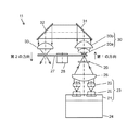
光源装置11は、固体光源である半導体レーザー20と、放熱板21と、コリメートレンズ22とを備えた固体光源ユニット23を備える。光源装置11は、さらにヒートシンク24、レンズ25、拡散板26、蛍光体とカラーフィルタを形成した基板27、モーター28、1組のレンズ30a及びレンズ30bからなる第1の集光レンズ30、ミラー31、ミラー32、第2の集光レンズ33を備える。尚、モーター28は、回転体の一例である。   The light source device 11 includes a solid-state light source unit 23 including a semiconductor laser 20 that is a solid-state light source, a heat radiating plate 21, and a collimating lens 22. The light source device 11 further includes a heat sink 24, a lens 25, a diffuser plate 26, a substrate 27 on which a phosphor and a color filter are formed, a motor 28, a first condenser lens 30 including a pair of lenses 30a and 30b, and a mirror 31. , A mirror 32 and a second condenser lens 33. The motor 28 is an example of a rotating body.

固体光源ユニット23は、放熱板21上に一定の間隔で2次元状に8個(2×4)の半導体レーザー20とコリメートレンズ22を正方配置したものである。ヒートシンク24は固体光源ユニット23を冷却するためのものである。半導体レーザー20は、440nmから455nmの波長幅で青色光を発光し出射する青色半導体レーザーである。   The solid-state light source unit 23 is a unit in which eight (2 × 4) semiconductor lasers 20 and a collimating lens 22 are squarely arranged on a heat radiating plate 21 in a two-dimensional manner at regular intervals. The heat sink 24 is for cooling the solid light source unit 23. The semiconductor laser 20 is a blue semiconductor laser that emits and emits blue light with a wavelength width of 440 nm to 455 nm.

複数の半導体レーザー20を出射した光は、対応するコリメートレンズ22により、それぞれ集光され平行な光束に変換される。光束群は凸面のレンズ25により集光され、拡散板26に入射する。拡散板26はガラス製で表面の微細な凹凸形状により光を拡散する。拡散光の最大強度の50%となる半値角度幅である拡散角度は略3度と小さい。拡散板26を出射した光は、光強度がピーク強度に対して13.5%となる直径をスポット径と定義すると、スポット径が1mm〜2mmのスポット光に重畳されて、基板27に入射する。拡散板26はそのスポット光の径が所望の径となるよう光を拡散させている。   The light emitted from the plurality of semiconductor lasers 20 is condensed by the corresponding collimator lens 22 and converted into a parallel light beam. The luminous flux group is collected by the convex lens 25 and enters the diffusion plate 26. The diffusing plate 26 is made of glass and diffuses light with a fine uneven shape on the surface. The diffusion angle, which is a half-value angle width that is 50% of the maximum intensity of the diffused light, is as small as about 3 degrees. The light emitted from the diffusion plate 26 is superimposed on the spot light having a spot diameter of 1 mm to 2 mm and is incident on the substrate 27 when the diameter at which the light intensity is 13.5% of the peak intensity is defined as the spot diameter. . The diffusion plate 26 diffuses the light so that the spot light has a desired diameter.

基板27は中央部にモーター28を備えた回転制御可能な円形基板であり、基板27上には蛍光体領域とカラーフィルタ領域が形成されている。基板27は透過率と熱伝導率が高いサファイア基板であり、かつ回転させることにより、励起光による蛍光体の温度上昇を抑制し、蛍光変換効率を安定に維持することができる。図1には、固体光源ユニット23からの光が基板27の蛍光体領域に入射する第1の方向と、第1の方向とは逆のカラーフィルタ領域に入射する第2の方向が示されている。   The substrate 27 is a circular substrate having a motor 28 at the center and capable of rotation control. A phosphor region and a color filter region are formed on the substrate 27. The substrate 27 is a sapphire substrate having high transmittance and thermal conductivity, and by rotating, the temperature rise of the phosphor due to excitation light can be suppressed and the fluorescence conversion efficiency can be stably maintained. FIG. 1 shows a first direction in which light from the solid-state light source unit 23 enters the phosphor region of the substrate 27 and a second direction in which the light enters the color filter region opposite to the first direction. Yes.

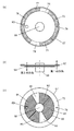
図2(a)〜(c)は蛍光体領域とカラーフィルタ領域が形成された基板27を示しており、図2(a)は基板27を第2の方向に見た平面図、図2(b)は基板27の正面図、図2(c)は基板27を第1の方向に見た底面図である。   2A to 2C show a substrate 27 on which a phosphor region and a color filter region are formed. FIG. 2A is a plan view of the substrate 27 viewed in the second direction. FIG. 2B is a front view of the substrate 27, and FIG. 2C is a bottom view of the substrate 27 viewed in the first direction.

基板27の第1の集光レンズ30側の面の外周側(外周輪帯)には蛍光体領域と拡散領域が形成されている。詳細には、図2(a)に示すように、基板27の外周側は6つのセグメントに分割され、そのうち2つのセグメント34、37は、緑色蛍光体が塗布された蛍光体領域であり、他の2つのセグメント35、38は、赤色蛍光体が塗布された蛍光体領域であり、残りの2つのセグメント36、39は表面を微細な凹凸形状にした青色光の拡散領域である。セグメント34とセグメント37、セグメント35とセグメント38、セグメント36とセグメント39は、基板27の回転軸に関して対称となる位置にそれぞれ形成されている。拡散角度は略10度である。緑成分を含む光を蛍光発光する緑色蛍光体として、Y3Al5O12:Ce3+、赤色成分を含む光を蛍光発光する赤色蛍光体として、CaAlSiN3:Eu2+を用いている。   A phosphor region and a diffusion region are formed on the outer peripheral side (outer peripheral zone) of the surface of the substrate 27 on the first condenser lens 30 side. Specifically, as shown in FIG. 2A, the outer peripheral side of the substrate 27 is divided into six segments, and two segments 34 and 37 are phosphor regions coated with a green phosphor. The two segments 35 and 38 are phosphor regions coated with a red phosphor, and the remaining two segments 36 and 39 are blue light diffusing regions having a surface with fine irregularities. The segment 34 and the segment 37, the segment 35 and the segment 38, and the segment 36 and the segment 39 are formed at positions that are symmetric with respect to the rotation axis of the substrate 27. The diffusion angle is approximately 10 degrees. Y3Al5O12: Ce3 + is used as a green phosphor that fluoresces light containing a green component, and CaAlSiN3: Eu2 + is used as a red phosphor that fluoresces light containing a red component.

基板27の内周側にはカラーフィルタが形成されたカラーフィルタ領域及び反射防止コートが形成された反射防止コート領域が形成されている。詳細には、図2(a)に示すように、基板27の内周側の領域は6つのセグメントに分割され、セグメント40、43には緑色光を透過するダイクロイックフィルタが、セグメント41、44には赤色光を透過するダイクロイックフィルタが、セグメント42、45には反射防止コートがそれぞれ形成されている。カラーフィルタ領域の緑透過フィルタ、赤透過フィルタ、および反射防止コートの各セグメントは、蛍光体領域の緑色蛍光体、赤色蛍光体、および拡散領域の各セグメントにそれぞれ対応するように分割されている。即ち、緑透過フィルタ、赤透過フィルタおよび反射防止コートは、それぞれ緑色蛍光体、赤色蛍光体および拡散領域の内側に形成されている。   On the inner peripheral side of the substrate 27, a color filter region in which a color filter is formed and an antireflection coating region in which an antireflection coating is formed are formed. Specifically, as shown in FIG. 2A, the inner peripheral region of the substrate 27 is divided into six segments, and the segments 40 and 43 have dichroic filters that transmit green light in the segments 41 and 44, respectively. Is a dichroic filter that transmits red light, and an anti-reflection coating is formed on each of the segments 42 and 45. Each segment of the green transmission filter, the red transmission filter, and the antireflection coating in the color filter region is divided so as to correspond to each segment of the green phosphor, the red phosphor, and the diffusion region in the phosphor region. That is, the green transmission filter, the red transmission filter, and the antireflection coat are formed inside the green phosphor, the red phosphor, and the diffusion region, respectively.

基板27の固体光源ユニット23側の面には、図2(c)に示すように、ダイクロイックフィルタ48が形成されている。ダイクロイックフィルタ48は、青色光が透過し、緑、赤を含む色光は反射するフィルタであり、蛍光体領域及び拡散領域を形成した面の裏面においてセグメント34〜39に対応した領域に形成されている。図2(a)(c)には、基板27の蛍光体領域に入射する励起光スポット46およびカラーフィルタ領域に入射する集光スポット47の様相が示されている。   A dichroic filter 48 is formed on the surface of the substrate 27 on the solid light source unit 23 side, as shown in FIG. The dichroic filter 48 is a filter that transmits blue light and reflects colored light including green and red, and is formed in a region corresponding to the segments 34 to 39 on the back surface of the surface on which the phosphor region and the diffusion region are formed. . 2A and 2C show the appearance of the excitation light spot 46 incident on the phosphor region of the substrate 27 and the condensing spot 47 incident on the color filter region.

図1に戻り、拡散板26で拡散された光は、第1の方向から、基板27の外周側に形成されたダイクロイックフィルタ48に入射し、青透過のダイクロイックフィルタ48を透過して、基板27の表面に形成された蛍光体領域又は拡散領域に入射する。蛍光体領域のセグメント34、35、37、38に入射した光は、緑、赤成分の色光を蛍光発光し、第1の方向に出射する。青透過のダイクロイックフィルタ48側に発光する光はダイクロイックフィルタ48で反射し、第1の方向に出射する。拡散領域であるセグメント36、39に入射した青色光は、拡散された後、第1の方向に出射する。第1の方向に出射した蛍光光と青色光は第1の集光レンズ30で集光される。第1の集光レンズ30は基板27から出射する光を±76度の範囲で集光し、平行光に変換する。   Returning to FIG. 1, the light diffused by the diffusing plate 26 enters the dichroic filter 48 formed on the outer peripheral side of the substrate 27 from the first direction, passes through the blue transmitting dichroic filter 48, and is transmitted to the substrate 27. Is incident on a phosphor region or a diffusion region formed on the surface. The light incident on the segments 34, 35, 37, and 38 of the phosphor region emits green and red component color lights and emits them in the first direction. The light emitted to the blue transmitting dichroic filter 48 side is reflected by the dichroic filter 48 and emitted in the first direction. The blue light that has entered the segments 36 and 39, which are diffusion regions, is diffused and then emitted in the first direction. The fluorescent light and the blue light emitted in the first direction are collected by the first condenser lens 30. The first condenser lens 30 condenses the light emitted from the substrate 27 in a range of ± 76 degrees and converts it into parallel light.

第1の集光レンズ30からの光は、ミラー31、32により反射し、第1の方向から、第1の方向とは逆の第2の方向へ光の進行方向が変換される。ミラー32からの光は第2の集光レンズ33で集光され、基板27の内周側に形成されたカラーフィルタ領域又は反射防止コート領域に入射する。入射する光の入射角は±33度で、スポット径は略2〜4mmである。   The light from the first condenser lens 30 is reflected by the mirrors 31 and 32, and the traveling direction of the light is converted from the first direction to the second direction opposite to the first direction. The light from the mirror 32 is collected by the second condenser lens 33 and is incident on the color filter region or the antireflection coating region formed on the inner peripheral side of the substrate 27. The incident angle of incident light is ± 33 degrees, and the spot diameter is approximately 2 to 4 mm.

緑色光はカラーフィルタ領域のセグメント40、43に入射し、赤色光はカラーフィルタ領域のセグメント41、44に入射する。カラーフィルタ領域に入射した緑色光、赤色光は、それぞれ不要な色成分の光がカットされ、色純度が良好な緑色光、赤色光となる。反射防止コート領域であるセグメント42、45に入射する青色光は透過する。このようにして、基板27から第2の方向に白色光が出射される。   Green light is incident on the segments 40 and 43 in the color filter region, and red light is incident on the segments 41 and 44 in the color filter region. The green light and red light incident on the color filter region are respectively cut with unnecessary color component light and become green light and red light with good color purity. Blue light incident on the segments 42 and 45, which are the antireflection coating regions, is transmitted. In this way, white light is emitted from the substrate 27 in the second direction.

蛍光体とカラーフィルタを形成した基板を1つの基板で構成しているため、基板重量が軽く、回転バランスの安定性が良好な基板が構成できる。また、蛍光体領域がカラーフィルタ領域よりも外周側に位置するため、小型で蛍光変換効率が高い光源装置11が構成できる。   Since the substrate on which the phosphor and the color filter are formed is configured as a single substrate, a substrate with a small substrate weight and excellent rotational balance stability can be configured. In addition, since the phosphor region is positioned on the outer peripheral side of the color filter region, the light source device 11 that is small and has high fluorescence conversion efficiency can be configured.

基板27は、熱伝導率がサファイアよりも低下するが、安価な水晶基板を用いてもよい。励起光から各蛍光光への波長変換効率の値をもとに、6つのセグメント34、35、36、37、38、39を適切な分割比(分割角度)とすることで、緑、赤、青色光の強度比が調整され、良好なホワイトバランスの白色光を得ることができる。   The substrate 27 has a thermal conductivity lower than that of sapphire, but an inexpensive quartz substrate may be used. Based on the value of the wavelength conversion efficiency from the excitation light to each fluorescent light, the six segments 34, 35, 36, 37, 38, 39 are set to appropriate division ratios (division angles), so that green, red, The intensity ratio of blue light is adjusted, and white light with good white balance can be obtained.

また、基板の外周側は、赤色蛍光体、緑色蛍光体、Ce付活YAG系黄色蛍光体、拡散領域の8つのセグメントに分割してもよい。そして、基板の内周側も8つのセグメントに分割し、黄色蛍光体を形成する領域に対応した領域に、黄色蛍光体により蛍光発光する黄色光に対応したカラーフィルタを形成する。黄色蛍光体を用いることにより、ホワイトバランスがさらに良好で、明るい白色光を得ることができる。   Further, the outer peripheral side of the substrate may be divided into eight segments of a red phosphor, a green phosphor, a Ce-activated YAG yellow phosphor, and a diffusion region. The inner peripheral side of the substrate is also divided into eight segments, and a color filter corresponding to yellow light that emits fluorescence by the yellow phosphor is formed in a region corresponding to the region where the yellow phosphor is formed. By using a yellow phosphor, white balance is further improved and bright white light can be obtained.

図1ではひとつの固体光源ユニットを用いているが、複数の固体光源ユニットをミラーで合成して用いてもよい。   Although one solid light source unit is used in FIG. 1, a plurality of solid light source units may be combined by a mirror.

以上のように本実施の形態の光源装置11は、固体光源からの励起光で蛍光発光する蛍光体領域と、カラーフィルタを形成したカラーフィルタ領域を、それぞれ外周側および内周側に備えたひとつの基板と、蛍光体領域からの光が励起光の入射方向である第1の方向に出射し、第1の方向とは逆の第2の方向からカラーフィルタ領域に入射するように導く光学系を備えるため、蛍光変換効率が高く、小型な光源装置が構成できる。   As described above, the light source device 11 according to the present embodiment includes a phosphor region that emits fluorescence with excitation light from a solid light source, and a color filter region in which a color filter is formed on the outer peripheral side and the inner peripheral side, respectively. And an optical system for guiding light from the phosphor region to be emitted in a first direction which is an incident direction of excitation light and to be incident on the color filter region from a second direction opposite to the first direction. Therefore, a small light source device with high fluorescence conversion efficiency can be configured.

(実施の形態2)
以下、図3及び図4を用いて、実施の形態2を説明する。図3は本実施の形態2にかかる光源装置12の構成図である。
(Embodiment 2)
Hereinafter, Embodiment 2 will be described with reference to FIGS. 3 and 4. FIG. 3 is a configuration diagram of the light source device 12 according to the second embodiment.

光源装置12は、固体光源である半導体レーザー50と、放熱板51と、コリメートレンズ52を備えた固体光源ユニット53を備える。光源装置12は、さらにヒートシンク54、レンズ55、拡散板56と蛍光基板57とモーター58とにより構成される基板ユニット60、カラーフィルタ基板59、1組のレンズ61a及びレンズ61bからなる第1の集光レンズ61、ミラー62、63、第2の集光レンズ64を備える。実施の形態1と異なる点は、蛍光基板57とカラーフィルタ基板59の2つの基板をひとつのモーター58の回転駆動軸の軸方向に並べて配置され、同時に回転するように取り付けられている点と、蛍光基板57の外径がカラーフィルタ基板59の外径よりも大きい点である。尚、モーター58は、回転体の一例である。   The light source device 12 includes a solid state light source unit 53 including a semiconductor laser 50 that is a solid state light source, a heat radiating plate 51, and a collimating lens 52. The light source device 12 further includes a substrate unit 60 constituted by a heat sink 54, a lens 55, a diffusion plate 56, a fluorescent substrate 57, and a motor 58, a color filter substrate 59, a pair of lenses 61a and a lens 61b. An optical lens 61, mirrors 62 and 63, and a second condenser lens 64 are provided. The difference from the first embodiment is that two substrates, a fluorescent substrate 57 and a color filter substrate 59, are arranged side by side in the axial direction of the rotational drive shaft of one motor 58, and are attached so as to rotate simultaneously. The outer diameter of the fluorescent substrate 57 is larger than the outer diameter of the color filter substrate 59. The motor 58 is an example of a rotating body.

複数の半導体レーザー50を出射した光は対応するコリメートレンズ52により、それぞれ集光され平行な光束に変換される。光束群は凸面のレンズ55により集光され、拡散板56に入射する。拡散板56はガラス製で表面の微細な凹凸形状で光を拡散する。拡散光の最大強度の50%となる半値角度幅である拡散角度は略3度と小さい。拡散板56を出射した光は、光強度がピーク強度に対して13.5%となる直径をスポット径と定義すると、スポット径が1mm〜2mmのスポット光に重畳され、蛍光基板57に入射する。拡散板56はそのスポット光の径が所望の径となるよう光を拡散させている。   The lights emitted from the plurality of semiconductor lasers 50 are respectively collected by the corresponding collimator lenses 52 and converted into parallel light beams. The light beam group is collected by the convex lens 55 and enters the diffusion plate 56. The diffusion plate 56 is made of glass and diffuses light with a fine uneven shape on the surface. The diffusion angle, which is a half-value angle width that is 50% of the maximum intensity of the diffused light, is as small as about 3 degrees. If the diameter at which the light intensity is 13.5% of the peak intensity is defined as the spot diameter, the light emitted from the diffusion plate 56 is superimposed on the spot light having a spot diameter of 1 mm to 2 mm and enters the fluorescent substrate 57. . The diffusion plate 56 diffuses light so that the spot light has a desired diameter.

蛍光基板57とカラーフィルタ基板59は、それぞれ円形基板であり、これら基板は同一のモーター58の回転駆動軸に配置され、モーター58によって回転駆動制御される。蛍光基板57は透過率と熱伝導率が高いサファイア基板であり、かつ回転させることにより、励起光による蛍光体の温度上昇を抑制し、蛍光変換効率を安定に維持することができる。図3には、固体光源ユニット53からの光が、蛍光基板57に形成された蛍光体に入射する第1の方向と、第1の方向とは逆のカラーフィルタ基板59に形成されたカラーフィルタに入射する第2の方向が示されている。   Each of the fluorescent substrate 57 and the color filter substrate 59 is a circular substrate, and these substrates are arranged on the rotation drive shaft of the same motor 58 and are rotationally controlled by the motor 58. The fluorescent substrate 57 is a sapphire substrate having a high transmittance and thermal conductivity, and by rotating, the temperature rise of the phosphor due to the excitation light can be suppressed and the fluorescence conversion efficiency can be stably maintained. In FIG. 3, the color filter formed on the color filter substrate 59 opposite to the first direction in which the light from the solid light source unit 53 is incident on the phosphor formed on the fluorescent substrate 57. A second direction of incidence is shown.

図4(a)〜(c)に基板ユニット60の構造を示す。図4(a)は基板ユニット60を第2の方向に見た平面図、図4(b)は基板ユニット60の正面図、図4(c)は基板ユニット60を第1の方向に見た底面図である。   4A to 4C show the structure of the substrate unit 60. FIG. 4A is a plan view of the substrate unit 60 as viewed in the second direction, FIG. 4B is a front view of the substrate unit 60, and FIG. 4C is a view of the substrate unit 60 as viewed in the first direction. It is a bottom view.

蛍光基板57の第1の集光レンズ61側の面には、図4(a)に示すように、透明なサファイアガラス基板に蛍光体領域と青色光の拡散領域が、6つのセグメント73、74、75、76、77、78として分割して形成されている。6つのセグメント73、74、75、76、77、78は、カラーフィルタ基板59の外径よりも外側の蛍光基板57の外周領域に形成されている。そのうち2つのセグメント73、76は緑色蛍光体が塗布された蛍光領域であり、セグメント74、77は赤色蛍光体が塗布された蛍光領域であり、セグメント75、78は表面を微細な凹凸形状にした拡散領域である。セグメント73とセグメント76、セグメント74とセグメント77、セグメント75とセグメント78は、モーター58の回転軸に関して対称となる位置にそれぞれ形成されている。   On the surface of the fluorescent substrate 57 on the first condensing lens 61 side, as shown in FIG. 4A, a phosphor region and a blue light diffusion region are provided on a transparent sapphire glass substrate, and six segments 73 and 74 are provided. , 75, 76, 77, 78. The six segments 73, 74, 75, 76, 77, 78 are formed in the outer peripheral region of the fluorescent substrate 57 outside the outer diameter of the color filter substrate 59. Two of the segments 73 and 76 are fluorescent regions coated with a green phosphor, the segments 74 and 77 are fluorescent regions coated with a red phosphor, and the segments 75 and 78 have a fine uneven surface. It is a diffusion region. The segment 73 and the segment 76, the segment 74 and the segment 77, and the segment 75 and the segment 78 are formed at positions that are symmetric with respect to the rotation axis of the motor 58, respectively.

蛍光基板57の蛍光体が形成された側の面とは反対側の面(固体光源ユニット53側の面)には、図4(c)に示すように、セグメント73〜78に対応した領域に、青色光が透過し、緑、赤を含む色光は反射するダイクロイックフィルタ72が形成されている。図4(a)(c)においては、蛍光基板57に入射する励起光の集光スポット79の様相を示している。   The surface of the fluorescent substrate 57 opposite to the surface on which the phosphor is formed (the surface on the solid light source unit 53 side) is in a region corresponding to the segments 73 to 78 as shown in FIG. A dichroic filter 72 that transmits blue light and reflects color light including green and red is formed. 4A and 4C show the appearance of the condensing spot 79 of the excitation light incident on the fluorescent substrate 57. FIG.

カラーフィルタ基板59は、カラーフィルタである6つのセグメント81、82、83、84、85、86に分割され、セグメント81、84は緑色光を透過するダイクロイックフィルタ、セグメント82、85は赤色光を透過するダイクロイックフィルタ、セグメント83、86は反射防止コート(青透過)を、それぞれ白板ガラス上に形成している。図4(a)と(c)において、蛍光基板57、カラーフィルタ基板59に入射する集光スポット80の様相が示されている。カラーフィルタの緑透過、赤透過、青透過のセグメント81〜86は、それぞれ各色光の蛍光基板57のセグメント73〜78に対応するように分割されている。即ち、セグメント81、84はセグメント73、76の内周側に、セグメント82、85はセグメント74、77の内周側に、セグメント83、86はセグメント75、78の内周側に、それぞれ位置している。   The color filter substrate 59 is divided into six segments 81, 82, 83, 84, 85, and 86 which are color filters, the segments 81 and 84 are dichroic filters that transmit green light, and the segments 82 and 85 transmit red light. The dichroic filter segments 83 and 86 each have an antireflection coating (blue transmission) formed on white glass. In FIGS. 4A and 4C, the appearance of the focused spot 80 incident on the fluorescent substrate 57 and the color filter substrate 59 is shown. The green transmission, red transmission, and blue transmission segments 81 to 86 of the color filter are divided so as to correspond to the segments 73 to 78 of the fluorescent substrate 57 of each color light, respectively. That is, the segments 81 and 84 are located on the inner circumference side of the segments 73 and 76, the segments 82 and 85 are located on the inner circumference side of the segments 74 and 77, and the segments 83 and 86 are located on the inner circumference side of the segments 75 and 78, respectively. ing.

図3に戻り、拡散板56で拡散された光は、第1の方向から、蛍光基板57の固体光源ユニット53側の面に形成されたダイクロイックフィルタ72に入射し、青透過のダイクロイックフィルタ72を透過して、蛍光基板57の第1の集光レンズ61側の面に形成された蛍光体領域又は拡散領域に入射する。蛍光体領域のセグメント73、74、76、77に入射した光は、緑、赤成分の色光を蛍光発光し、第1の方向に出射する。青透過のダイクロイックフィルタ72側に蛍光発光する光はダイクロイックフィルタ72で反射し、第1の方向に出射する。拡散領域のセグメント75、78に入射した青色光は、拡散された後、第1の方向に出射する。   Returning to FIG. 3, the light diffused by the diffusion plate 56 enters the dichroic filter 72 formed on the surface of the fluorescent light source 57 on the solid light source unit 53 side from the first direction, and passes through the blue transmitting dichroic filter 72. The light passes through and enters the phosphor region or the diffusion region formed on the surface of the fluorescent substrate 57 on the first condenser lens 61 side. The light incident on the segments 73, 74, 76, and 77 of the phosphor region emits green and red component color lights and emits them in the first direction. Light that emits fluorescence toward the blue transmitting dichroic filter 72 is reflected by the dichroic filter 72 and emitted in the first direction. The blue light that has entered the segments 75 and 78 of the diffusion region is diffused and then emitted in the first direction.

第1の集光レンズ61は蛍光基板57から出射する光を±76度の範囲で集光し、略平行光に変換する。第1の集光レンズ61からの光は、ミラー62、63により、第1の方向から、第1の方向とは逆の第2の方向へ光の進行方向が変換される。ミラー63からの光は第2の集光レンズ64で集光され、蛍光基板57を透過後、カラーフィルタ基板59に集光される。カラーフィルタ基板59に入射する光の入射角は±33度で、スポット径は略2〜4mmである。   The first condenser lens 61 condenses the light emitted from the fluorescent substrate 57 in a range of ± 76 degrees and converts it into substantially parallel light. The traveling direction of the light from the first condenser lens 61 is converted by the mirrors 62 and 63 from the first direction to the second direction opposite to the first direction. The light from the mirror 63 is collected by the second condenser lens 64, passes through the fluorescent substrate 57, and then is collected on the color filter substrate 59. The incident angle of light incident on the color filter substrate 59 is ± 33 degrees, and the spot diameter is approximately 2 to 4 mm.

緑色光はカラーフィルタ基板59のセグメント81、84に入射し、赤色光はカラーフィルタ基板59のセグメント82、85に入射する。カラーフィルタ基板59に入射した緑、赤の光は、不要な色成分の光がカットされ、色純度が良好な緑、赤の色光となる。カラーフィルタ基板59のセグメント83、86に入射する青色光は透過する。このようにして、カラーフィルタ基板59から第2の方向に白色光が出射される。本実施の形態では、蛍光基板がカラーフィルタ基板よりも大口径、換言すればカラーフィルタ基板は蛍光基板よりも小口径であるため、蛍光変換効率が高く、小型な光源装置が構成できる。   Green light is incident on the segments 81 and 84 of the color filter substrate 59, and red light is incident on the segments 82 and 85 of the color filter substrate 59. The green and red light incident on the color filter substrate 59 is converted into green and red color light with good color purity by cutting off light of unnecessary color components. Blue light incident on the segments 83 and 86 of the color filter substrate 59 is transmitted. In this way, white light is emitted from the color filter substrate 59 in the second direction. In the present embodiment, since the fluorescent substrate has a larger diameter than the color filter substrate, in other words, the color filter substrate has a smaller diameter than the fluorescent substrate, the fluorescent conversion efficiency is high, and a small light source device can be configured.

蛍光基板57は、熱伝導率がサファイアよりも低下するが、安価な水晶基板を用いてもよい。励起光から各蛍光光への波長変換効率の値をもとに、6つのセグメント73、74、75、76、77、78を適切な分割比(分割角度)とすることで、緑、赤、青色光の強度比が調整され、良好なホワイトバランスの白色光を得ることができる。   The fluorescent substrate 57 has a thermal conductivity lower than that of sapphire, but an inexpensive quartz substrate may be used. Based on the value of the wavelength conversion efficiency from the excitation light to each fluorescent light, the six segments 73, 74, 75, 76, 77, 78 are set to appropriate division ratios (division angles), so that green, red, The intensity ratio of blue light is adjusted, and white light with good white balance can be obtained.

また、蛍光基板は赤色蛍光体、緑色蛍光体、Ce付活YAG系黄色蛍光体、拡散領域の8つのセグメントに分割してもよい。そして、カラーフィルタ基板も8つのセグメントに分割し、黄色蛍光体を形成する領域に対応した領域に、黄色蛍光体により蛍光発光する黄色光に対応したカラーフィルタを形成する。黄色蛍光体を用いることにより、ホワイトバランスがさらに良好で、明るい白色光を得ることができる。   Further, the fluorescent substrate may be divided into eight segments of a red phosphor, a green phosphor, a Ce-activated YAG yellow phosphor, and a diffusion region. The color filter substrate is also divided into eight segments, and a color filter corresponding to yellow light that emits fluorescence by the yellow phosphor is formed in a region corresponding to a region where the yellow phosphor is formed. By using a yellow phosphor, white balance is further improved and bright white light can be obtained.

図3では1つの固体光源ユニットを用いているが、複数の固体光源ユニットをミラーで合成して用いてもよい。   In FIG. 3, one solid light source unit is used, but a plurality of solid light source units may be combined by a mirror.

以上のように本実施の形態の光源装置12は、固体光源からの励起光で蛍光発光する蛍光基板と、蛍光基板よりも小さい径のカラーフィルタ基板を、1つのモーターに配置し、蛍光体領域からの光が励起光の入射方向である第1の方向に出射し、第1の方向とは逆の第2の方向からカラーフィルタ領域に入射するように導く光学系を備える。このため、蛍光変換効率が高く、小型な光源装置が構成できる。   As described above, the light source device 12 according to the present embodiment includes a fluorescent substrate that emits fluorescence with excitation light from a solid light source and a color filter substrate having a diameter smaller than that of the fluorescent substrate in one motor, and a phosphor region. Is provided with an optical system that guides the light from the first direction, which is the incident direction of the excitation light, and enters the color filter region from the second direction opposite to the first direction. For this reason, a fluorescence conversion efficiency is high and a small light source device can be constituted.

なお、実施の形態2では、カラーフィルタ基板59は蛍光基板57よりも小口径に形成されているが、カラーフィルタ基板59のカラーフィルタ及び反射防止コートを形成した部分が蛍光基板57よりも小口径であればよく、カラーフィルタ基板59自体の外径は蛍光基板57と同程度に構成することもできる。この場合、蛍光基板57とカラーフィルタ基板59との配置は逆にすることもできる。そして、この拡散部に拡散板56の機能をもたせることにより、カラーフィルタ基板59と拡散板56とを一体に構成することができる。   In the second embodiment, the color filter substrate 59 is formed with a smaller diameter than the fluorescent substrate 57, but the portion of the color filter substrate 59 where the color filter and the antireflection coating are formed has a smaller diameter than the fluorescent substrate 57. The outer diameter of the color filter substrate 59 itself may be the same as that of the fluorescent substrate 57. In this case, the arrangement of the fluorescent substrate 57 and the color filter substrate 59 can be reversed. The color filter substrate 59 and the diffusion plate 56 can be integrally formed by providing the diffusion portion with the function of the diffusion plate 56.

また、実施の形態2では、蛍光基板57が第1の集光レンズ61側に、カラーフィルタ基板59が拡散板56側に配置されるが、蛍光基板57とカラーフィルタ基板59との配置は逆にすることもできる。   In the second embodiment, the fluorescent substrate 57 is disposed on the first condenser lens 61 side and the color filter substrate 59 is disposed on the diffusion plate 56 side. However, the arrangement of the fluorescent substrate 57 and the color filter substrate 59 is reversed. It can also be.

(実施の形態3)
図5は、実施の形態3を示す光源装置13の構成図である。光源装置13は、固体光源である半導体レーザー100と、放熱板101と、コリメートレンズ102とを備えた固体光源ユニット103を備える。光源装置13は、さらにヒートシンク104、レンズ105、拡散板106、蛍光体とカラーフィルタを形成した基板107、モーター108、1組のレンズ110a及びレンズ110bからなる第1の集光レンズ110、ミラー111、112、第2の集光レンズ113を備える。以上は実施の形態1の光源装置11と同様の構成である。本実施の形態3において実施の形態1と異なる点は、ミラー111とミラー112の間に、レンズ114、115を配置している点である。また、基板107の詳細な構成は光源装置11の基板27と同様であるので、その重複説明は省略する。
(Embodiment 3)
FIG. 5 is a configuration diagram of the light source device 13 according to the third embodiment. The light source device 13 includes a solid light source unit 103 including a semiconductor laser 100 that is a solid light source, a heat radiating plate 101, and a collimating lens 102. The light source device 13 further includes a heat sink 104, a lens 105, a diffusion plate 106, a substrate 107 on which a phosphor and a color filter are formed, a motor 108, a first condenser lens 110 including a pair of lenses 110a and 110b, and a mirror 111. , 112 and a second condenser lens 113. The above is the same configuration as the light source device 11 of the first embodiment. The third embodiment is different from the first embodiment in that lenses 114 and 115 are arranged between the mirror 111 and the mirror 112. Further, since the detailed configuration of the substrate 107 is the same as that of the substrate 27 of the light source device 11, the duplicate description thereof is omitted.

複数の半導体レーザー100を出射した光は対応するコリメートレンズ102により、それぞれ集光され平行な光束に変換される。光束群は凸面のレンズ105により集光され、拡散板106に入射する。拡散板106はガラス製で表面の微細な凹凸形状で光を拡散する。拡散光の最大強度の50%となる半値角度幅である拡散角度は略3度と小さい。拡散板106を出射した光は、光強度がピーク強度に対して13.5%となる直径をスポット径と定義すると、スポット径が1mm〜2mmのスポット光に重畳され、基板107に入射する。拡散板106はそのスポット光の径が所望の径となるように光を拡散させている。   The light emitted from the plurality of semiconductor lasers 100 is condensed by the corresponding collimator lens 102 and converted into a parallel light beam. The light beam group is collected by the convex lens 105 and enters the diffusion plate 106. The diffusion plate 106 is made of glass and diffuses light with a fine uneven shape on the surface. The diffusion angle, which is a half-value angle width that is 50% of the maximum intensity of the diffused light, is as small as about 3 degrees. The light emitted from the diffusion plate 106 is superimposed on the spot light having a spot diameter of 1 mm to 2 mm and is incident on the substrate 107 when the diameter at which the light intensity is 13.5% of the peak intensity is defined as the spot diameter. The diffusion plate 106 diffuses the light so that the spot light has a desired diameter.

基板107は中央部にモーター108を備えた回転制御可能な円形基板であり、基板107の外周側には蛍光体領域及び拡散領域が形成され、内周側にはカラーフィルタ領域および反射防止コート領域が形成されている。基板107は透過率と熱伝導率が高いサファイア基板であり、かつ回転させることにより、励起光による蛍光体の温度上昇を抑制し、蛍光変換効率を安定に維持することができる。図5には固体光源ユニット103からの光が、基板107の蛍光体領域に入射する第1の方向と、基板107のカラーフィルタ領域に入射する第2の方向を示している。基板107の蛍光体領域に入射した光は、緑、赤成分の色光を蛍光発光し、第1の方向に出射する。基板107の拡散領域に入射した青色光は、拡散された後、第1の方向に出射する。   The substrate 107 is a rotationally controllable circular substrate having a motor 108 at the center, and a phosphor region and a diffusion region are formed on the outer peripheral side of the substrate 107, and a color filter region and an antireflection coating region on the inner peripheral side. Is formed. The substrate 107 is a sapphire substrate having a high transmittance and thermal conductivity, and by rotating, the temperature rise of the phosphor due to the excitation light can be suppressed and the fluorescence conversion efficiency can be stably maintained. FIG. 5 shows a first direction in which light from the solid light source unit 103 enters the phosphor region of the substrate 107 and a second direction in which the light enters the color filter region of the substrate 107. The light incident on the phosphor region of the substrate 107 fluoresces green and red component color lights and emits them in the first direction. The blue light incident on the diffusion region of the substrate 107 is diffused and then emitted in the first direction.

第1の方向に出射した蛍光光と青色光は第1の集光レンズ110で集光される。第1の集光レンズ110は基板107から出射する光を±76度の範囲で集光し、平行光に変換する。第1の集光レンズ110からの光は、ミラー111を反射後、レンズ114とレンズ115により、光束径を小径化された平行光となる。レンズ115を出射した光はミラー112により、第1の方向から、第1の方向とは逆の第2の方向へ光の進行方向が変換される。ミラー112からの光は第2の集光レンズ113で基板107のカラーフィルタ領域または反射防止コート領域に集光される。カラーフィルタ領域または反射防止コート領域に入射する光の入射角は±33度で、スポット径は略2〜4mmである。   The fluorescent light and blue light emitted in the first direction are collected by the first condenser lens 110. The first condenser lens 110 condenses the light emitted from the substrate 107 in a range of ± 76 degrees and converts it into parallel light. The light from the first condensing lens 110 is reflected by the mirror 111, and then becomes parallel light whose beam diameter is reduced by the lens 114 and the lens 115. The light emitted from the lens 115 is converted by the mirror 112 from the first direction to the second direction opposite to the first direction. The light from the mirror 112 is condensed by the second condenser lens 113 on the color filter region or the antireflection coating region of the substrate 107. The incident angle of light incident on the color filter region or the antireflection coating region is ± 33 degrees, and the spot diameter is approximately 2 to 4 mm.

カラーフィルタ領域に入射した緑、赤の光は、不要な色成分の光がカットされ、色純度が良好な緑、赤の色光となる。反射防止コート領域に入射する青色光は透過する。このようにして、基板107から第2の方向に白色光が出射される。   The green and red light incident on the color filter region is cut into unnecessary color component light, and becomes green and red color light with good color purity. Blue light incident on the antireflection coating region is transmitted. In this way, white light is emitted from the substrate 107 in the second direction.

以上のように、本実施の形態の光源装置13は、固体光源からの励起光で蛍光発光する蛍光体領域と、カラーフィルタを形成したカラーフィルタ領域を備えた1つの基板と、蛍光体領域からの光が励起光の入射方向である第1の方向に出射し、第1の方向とは逆の第2の方向からカラーフィルタ領域に入射するように導く。また、光束径を小径化するためのレンズ114とレンズ115を有する光学系を備えるため、基板107を実施の形態1で開示した光源装置11の基板27に比べて小径に構成することがで、蛍光変換効率が高く、非常に小型な光源装置が構成できる。   As described above, the light source device 13 according to the present embodiment includes a phosphor region that emits fluorescence with excitation light from a solid light source, a single substrate that includes a color filter region in which a color filter is formed, and a phosphor region. Is emitted in a first direction that is the incident direction of the excitation light, and is guided so as to enter the color filter region from a second direction opposite to the first direction. In addition, since the optical system having the lens 114 and the lens 115 for reducing the light beam diameter is provided, the substrate 107 can be configured to have a smaller diameter than the substrate 27 of the light source device 11 disclosed in the first embodiment. A very small light source device with high fluorescence conversion efficiency can be constructed.

なお、実施の形態3の光源装置13は、基板107として、実施の形態1で開示した光源装置11の基板27と同様のものを用いたが、実施の形態2で開示した光源装置12の基板ユニット60と同様のものを用いることもできる。   The light source device 13 of the third embodiment uses the same substrate 107 as the substrate 27 of the light source device 11 disclosed in the first embodiment, but the substrate of the light source device 12 disclosed in the second embodiment. The same unit 60 can also be used.

(実施の形態4)
図6は、本開示の実施の形態4を示す投写型表示装置10である。画像形成手段として、1つのDMDを用いている。
(Embodiment 4)
FIG. 6 shows a projection display apparatus 10 according to the fourth embodiment of the present disclosure. One DMD is used as the image forming means.

光源装置11は、固体光源である半導体レーザー20、放熱板21、コリメートレンズ22から構成される固体光源ユニット23を備える。光源装置11はさらに、ヒートシンク24、レンズ25、拡散板26、蛍光体とカラーフィルタを形成した基板27、モーター28、第1の集光レンズ30、ミラー31、32、第2の集光レンズ33を備える。図6には固体光源ユニット23からの光が、基板27の蛍光体領域に入射する第1の方向と、基板27のカラーフィルタ領域に入射する第2の方向を示している。以上は本開示の実施の形態1の光源装置11と同じ構成であり、図6において図1及び図2と同一部分には同一符号を付している。   The light source device 11 includes a solid light source unit 23 including a semiconductor laser 20 that is a solid light source, a heat radiating plate 21, and a collimating lens 22. The light source device 11 further includes a heat sink 24, a lens 25, a diffusion plate 26, a substrate 27 on which a phosphor and a color filter are formed, a motor 28, a first condenser lens 30, mirrors 31 and 32, and a second condenser lens 33. Is provided. FIG. 6 shows a first direction in which light from the solid light source unit 23 enters the phosphor region of the substrate 27 and a second direction in which the light enters the color filter region of the substrate 27. The above is the same configuration as that of the light source device 11 according to the first embodiment of the present disclosure. In FIG. 6, the same parts as those in FIGS. 1 and 2 are denoted by the same reference numerals.

光源装置11から出射する光は、基板27の回転により、時系列的に赤、緑、青色光を出射する。光源装置11からの光は集光レンズ120により、平行光に変換された後、複数のレンズ素子から構成される第1のレンズアレイ板121に入射する。第1のレンズアレイ板121に入射した光束は多数の光束に分割される。分割された多数の光束は、複数のレンズから構成される第2のレンズアレイ板122に収束する。第1のレンズアレイ板121のレンズ素子はDMD127と相似形の開口形状である。第2のレンズアレイ板122のレンズ素子は第1のレンズアレイ板121とDMD127が略共役関係となるようにその焦点距離を決めている。第2のレンズアレイ板122から出射した光は重畳用レンズ123に入射する。重畳用レンズ123は第2のレンズアレイ板122の各レンズ素子からの出射した光をDMD127上に重畳照明するためのレンズである。   The light emitted from the light source device 11 emits red, green, and blue light in time series by the rotation of the substrate 27. The light from the light source device 11 is converted into parallel light by the condenser lens 120 and then enters the first lens array plate 121 composed of a plurality of lens elements. The light beam incident on the first lens array plate 121 is divided into a number of light beams. The many divided light beams converge on the second lens array plate 122 composed of a plurality of lenses. The lens elements of the first lens array plate 121 have an opening shape similar to DMD127. The focal length of the lens elements of the second lens array plate 122 is determined so that the first lens array plate 121 and the DMD 127 have a substantially conjugate relationship. The light emitted from the second lens array plate 122 enters the superimposing lens 123. The superimposing lens 123 is a lens for superimposing and illuminating the light emitted from each lens element of the second lens array plate 122 on the DMD 127.

重畳用レンズ123からの光は、ミラー124で反射された後、フィールドレンズ125に入射する。フィールドレンズ125は照明光を効率よく投写レンズ128に集光する。フィールドレンズ125からの照明光は全反射プリズム126に入射する。全反射プリズム126は2つのプリズムから構成され、互いのプリズムの近接面には薄い空気層を形成し、空気層は臨界角以上の角度で入射する光を全反射する。フィールドレンズ125からの照明光は全反射させて、DMD127を照明するとともに、DMDから出射する投写光を透過する。このように、集光レンズ120〜全反射プリズム126は、被照明領域であるDMDを照明する照明光学系を構成する。ミラー偏向型のDMDは画像形成素子の一例である。   The light from the superimposing lens 123 is reflected by the mirror 124 and then enters the field lens 125. The field lens 125 condenses the illumination light on the projection lens 128 efficiently. The illumination light from the field lens 125 enters the total reflection prism 126. The total reflection prism 126 is composed of two prisms. A thin air layer is formed on the adjacent surfaces of the prisms, and the air layer totally reflects light incident at an angle greater than the critical angle. The illumination light from the field lens 125 is totally reflected to illuminate the DMD 127 and to transmit the projection light emitted from the DMD. Thus, the condensing lens 120 to the total reflection prism 126 constitute an illumination optical system that illuminates the DMD that is the illuminated area. The mirror deflection type DMD is an example of an image forming element.

DMD127に入射する光は映像信号に応じて、画像形成に必要な光束のみを偏向し、全反射プリズム126を透過後、投写レンズ128に入射する。投写レンズ128はDMD127で変調形成される画像光を拡大投写する。1つのDMDを用い、光源装置に本開示の実施の形態1の光源装置11を用いるため、小型で明るい、長寿命の投写型表示装置が構成できる。   The light incident on the DMD 127 deflects only the light beam necessary for image formation according to the video signal, passes through the total reflection prism 126, and then enters the projection lens 128. The projection lens 128 enlarges and projects the image light modulated and formed by the DMD 127. Since one DMD is used and the light source device 11 according to the first embodiment of the present disclosure is used as the light source device, a small, bright, long-life projection display device can be configured.

投写画像の均一性を確保するためのインテグレータ光学系として、2枚のレンズアレイ板を用いているが、ロッドを用いて構成してもよい。   Although two lens array plates are used as an integrator optical system for ensuring the uniformity of the projected image, a rod may be used.

以上のように、本開示の投写型表示装置は、固体光源からの励起光で蛍光発光する蛍光体領域と、カラーフィルタを形成したカラーフィルタ領域を、それぞれ外周側および内周側に備えたひとつの基板と、蛍光体領域からの光が励起光の入射方向である第1の方向に出射し、第1の方向とは逆の第2の方向からカラーフィルタ領域に入射するように導く光学系を備えた光源装置を備える。そして、かかる光源装置を使用し、レンズアレイを用いたインテグレータ照明光学系と、1つのDMDを用いて構成した投写型表示装置であるため、小型で、投写画像の均一性が高く、明るい投写型表示装置が構成できる。   As described above, the projection display device according to the present disclosure includes a phosphor region that emits fluorescence with excitation light from a solid-state light source, and a color filter region in which a color filter is formed on each of the outer peripheral side and the inner peripheral side. And an optical system for guiding light from the phosphor region to be emitted in a first direction which is an incident direction of excitation light and to be incident on the color filter region from a second direction opposite to the first direction. The light source device provided with. And since it is the projection type display apparatus comprised using the integrator illumination optical system which used such a light source device and the lens array, and one DMD, it is small, the uniformity of a projection image is high, and a bright projection type A display device can be configured.

なお、実施の形態4の投写型表示装置10は、光源装置として実施の形態1で開示した光源装置11を用いるが、実施の形態2、3で開示した光源装置12、13を用いることもできる。   The projection display device 10 according to the fourth embodiment uses the light source device 11 disclosed in the first embodiment as the light source device, but the light source devices 12 and 13 disclosed in the second and third embodiments can also be used. .

本開示は、画像形成手段を用いた投写型表示装置に適用可能である。   The present disclosure is applicable to a projection display apparatus using an image forming unit.

10 投写型表示装置
11,12,13 光源装置
20,50,100 半導体レーザー
21,51,101 放熱板
22,52,102 コリメートレンズ
23,53,103 固体光源ユニット
24,54,104 ヒートシンク
25,30a,30b,55,61a,61b,105,110a,110b,114,115 レンズ
26,56,106 拡散板
27,107 基板
28,58,108 モーター
30,61,110 第1の集光レンズ
31,32,62,63,111,112,124 ミラー
33,64,113 第2の集光レンズ
34,35,36,37,38,39,40,41,42,43,44,45,73,74,75,76,77,78,81,82,83,84,85,86 セグメント
48,72 ダイクロイックフィルタ
57 蛍光基板
59 カラーフィルタ基板
60 基板ユニット
120 集光レンズ
121 第1のレンズアレイ板
122 第2のレンズアレイ板
123 重畳用レンズ
125 フィールドレンズ
126 全反射プリズム
127 DMD
128 投写レンズ
DESCRIPTION OF SYMBOLS 10 Projection type display device 11, 12, 13 Light source device 20, 50, 100 Semiconductor laser 21, 51, 101 Heat sink 22, 52, 102 Collimating lens 23, 53, 103 Solid light source unit 24, 54, 104 Heat sink 25, 30a , 30b, 55, 61a, 61b, 105, 110a, 110b, 114, 115 Lens 26, 56, 106 Diffuser 27, 107 Substrate 28, 58, 108 Motor 30, 61, 110 First condenser lens 31, 32 , 62, 63, 111, 112, 124 Mirror 33, 64, 113 Second condenser lens 34, 35, 36, 37, 38, 39, 40, 41, 42, 43, 44, 45, 73, 74, 75, 76, 77, 78, 81, 82, 83, 84, 85, 86 Segment 48, 72 Dichroic Filter 57 fluorescent substrate 59 color filter substrate 60 substrate unit 120 condenser lens 121 first lens array plate 122 second lens array plate 123 superposition lens 125 field lens 126 total reflection prism 127 DMD
128 Projection lens

Claims (13)

固体光源と、
前記固体光源からの励起光により蛍光発光する蛍光体を形成した蛍光体領域と、前記蛍光体領域の内側にカラーフィルタを形成したカラーフィルタ領域と、を備えた基板と、
前記蛍光体領域からの光が、前記励起光の入射方向である第1の方向に出射し、前記第1の方向とは逆の第2の方向から前記カラーフィルタ領域に入射するように導く光学手段と、
を備えた、光源装置。
A solid light source;
A substrate comprising: a phosphor region in which a phosphor that emits fluorescence by excitation light from the solid light source; and a color filter region in which a color filter is formed inside the phosphor region;
Optical that guides the light from the phosphor region to be emitted in a first direction that is the incident direction of the excitation light and to be incident on the color filter region from a second direction opposite to the first direction. Means,
A light source device comprising:
固体光源と、
前記固体光源からの励起光により蛍光発光する蛍光基板と、
カラーフィルタを形成したカラーフィルタ基板と、
前記励起光の入射方向である第1の方向に出射する前記蛍光基板からの光を、前記第1の方向とは逆の第2の方向から前記カラーフィルタ基板に入射するように導く光学手段と、を備え、
前記蛍光基板と前記カラーフィルタ基板は、同一の回転駆動軸の軸方向に並んで配置され、
前記カラーフィルタは、前記蛍光基板よりも小口径に形成される、光源装置。
A solid light source;
A fluorescent substrate that emits fluorescence by excitation light from the solid-state light source;
A color filter substrate on which a color filter is formed;
Optical means for guiding light from the fluorescent substrate that is emitted in a first direction, which is an incident direction of the excitation light, so as to be incident on the color filter substrate from a second direction opposite to the first direction; With
The fluorescent substrate and the color filter substrate are arranged side by side in the axial direction of the same rotational drive shaft,
The color filter is a light source device having a smaller diameter than the fluorescent substrate.
前記光学手段は、前記第1の方向に蛍光発光する光を集光して略平行光に変換する第1の集光レンズと、前記第1の方向を前記第2の方向に変換するミラーと、前記略平行光の光束を前記カラーフィルタ領域に集光する第2の集光レンズとを備えた、請求項1または2記載の光源装置。   The optical means includes a first condenser lens that condenses the fluorescent light in the first direction and converts the light into substantially parallel light, and a mirror that converts the first direction into the second direction. The light source device according to claim 1, further comprising: a second condenser lens that condenses the luminous flux of the substantially parallel light on the color filter region. 前記光学手段は、前記第1の方向に蛍光発光する光を集光して略平行光に変換する第1の集光レンズと、前記第1の集光レンズからの略平行光を小径化するレンズと、小径化された平行光を前記カラーフィルタ領域に集光する第2の集光レンズと、前記第1の方向を前記第2の方向に変換するミラーと、を備えた、請求項1または2記載の光源装置。   The optical means reduces the diameter of the first condensing lens that condenses the fluorescent light in the first direction and converts it into substantially parallel light, and the substantially parallel light from the first condensing lens. 2. A lens, a second condensing lens that condenses the collimated light having a reduced diameter on the color filter region, and a mirror that converts the first direction into the second direction. Or the light source device of 2. 前記固体光源は青色半導体レーザーである、請求項1または2記載の光源装置。   The light source device according to claim 1, wherein the solid-state light source is a blue semiconductor laser. 前記蛍光体領域と前記カラーフィルタ領域とが形成された基板は回転制御可能な円形状基板である、請求項1記載の光源装置。   The light source device according to claim 1, wherein the substrate on which the phosphor region and the color filter region are formed is a circular substrate that can be rotationally controlled. 前記蛍光体領域と前記カラーフィルタ領域とが形成された基板はサファイア基板である、請求項1記載の光源装置。   The light source device according to claim 1, wherein the substrate on which the phosphor region and the color filter region are formed is a sapphire substrate. 前記蛍光体領域と前記カラーフィルタ領域とが形成された基板は水晶基板である、請求項1記載の光源装置。   The light source device according to claim 1, wherein the substrate on which the phosphor region and the color filter region are formed is a quartz substrate. 前記蛍光基板と前記カラーフィルタ基板とは回転制御可能な円形状基板である、請求項2記載の光源装置。   The light source device according to claim 2, wherein the fluorescent substrate and the color filter substrate are circular substrates that can be rotationally controlled. 前記蛍光基板はサファイア基板である、請求項2記載の光源装置。   The light source device according to claim 2, wherein the fluorescent substrate is a sapphire substrate. 前記蛍光基板は水晶基板である、請求項2記載の光源装置。   The light source device according to claim 2, wherein the fluorescent substrate is a quartz substrate. 請求項1または2記載の光源装置と、前記光源装置からの光を集光する照明光学系と、前記照明光学系で集光された光から映像信号に応じて画像を形成する画像形成素子と、前記画像形成素子で形成された前記画像を拡大投写する投写レンズと、を備える、投写型表示装置。   The light source device according to claim 1, an illumination optical system that condenses light from the light source device, and an image forming element that forms an image according to a video signal from the light collected by the illumination optical system; And a projection lens for enlarging and projecting the image formed by the image forming element. 前記画像形成素子がミラー偏向型のデジタル・マイクロミラー・デバイス(DMD)である、請求項12記載の投写型表示装置。   The projection display device according to claim 12, wherein the image forming element is a mirror deflection type digital micromirror device (DMD).
JP2016028454A 2015-03-19 2016-02-18 Light source and projection type display device Pending JP2016177272A (en)

Priority Applications (1)

Application Number Priority Date Filing Date Title
US15/058,209 US20160274446A1 (en) 2015-03-19 2016-03-02 Light source apparatus and projection display apparatus

Applications Claiming Priority (2)

Application Number Priority Date Filing Date Title
JP2015056725 2015-03-19

Publications (1)

Publication Number Publication Date
JP2016177272A true JP2016177272A (en) 2016-10-06

Family

ID=57070050

Family Applications (1)

Application Number Title Priority Date Filing Date
JP2016028454A Pending JP2016177272A (en) 2015-03-19 2016-02-18 Light source and projection type display device

Country Status (1)

Country Link
JP (1) JP2016177272A (en)

Cited By (5)

* Cited by examiner, † Cited by third party
Publication number Priority date Publication date Assignee Title
WO2018084140A1 (en) * 2016-11-02 2018-05-11 京セラ株式会社 Substrate for color wheel, color wheel, projector, and method for manufacturing substrate for color wheel
CN108693637A (en) * 2017-04-10 2018-10-23 美题隆精密光学(上海)有限公司 combination wheel for light conversion
WO2020004505A1 (en) * 2018-06-29 2020-01-02 パナソニックIpマネジメント株式会社 Phosphor wheel device
JP2020064269A (en) * 2018-10-12 2020-04-23 パナソニックIpマネジメント株式会社 Wheel device, light source device, and projection type video display device
US11874591B2 (en) 2021-03-23 2024-01-16 Casio Computer Co., Ltd. Light source apparatus, projection apparatus and color wheel device

Cited By (11)

* Cited by examiner, † Cited by third party
Publication number Priority date Publication date Assignee Title
WO2018084140A1 (en) * 2016-11-02 2018-05-11 京セラ株式会社 Substrate for color wheel, color wheel, projector, and method for manufacturing substrate for color wheel
JPWO2018084140A1 (en) * 2016-11-02 2019-09-19 京セラ株式会社 Color wheel substrate, color wheel and projector, and method for manufacturing color wheel substrate
CN108693637A (en) * 2017-04-10 2018-10-23 美题隆精密光学(上海)有限公司 combination wheel for light conversion
CN108693637B (en) * 2017-04-10 2024-04-26 美题隆精密光学(上海)有限公司 Combined wheel for light conversion
WO2020004505A1 (en) * 2018-06-29 2020-01-02 パナソニックIpマネジメント株式会社 Phosphor wheel device
JPWO2020004505A1 (en) * 2018-06-29 2021-08-05 パナソニックIpマネジメント株式会社 Phosphor wheel device
US11340445B2 (en) 2018-06-29 2022-05-24 Panasonic Intellectual Property Management Co., Ltd. Phosphor wheel device
JP7296604B2 (en) 2018-06-29 2023-06-23 パナソニックIpマネジメント株式会社 Phosphor wheel device
JP2020064269A (en) * 2018-10-12 2020-04-23 パナソニックIpマネジメント株式会社 Wheel device, light source device, and projection type video display device
JP7365595B2 (en) 2018-10-12 2023-10-20 パナソニックIpマネジメント株式会社 Light source device and projection type image display device
US11874591B2 (en) 2021-03-23 2024-01-16 Casio Computer Co., Ltd. Light source apparatus, projection apparatus and color wheel device

Similar Documents

Publication Publication Date Title
JP5906416B2 (en) Illumination device and projection display device
JP6238387B2 (en) Light source device and projector
JP5605047B2 (en) Light source device and projection display device using the same
JP6371439B1 (en) Light source device and projection display device
US20130107226A1 (en) Projection system comprising a solid state light source and a luminsecent material
JP2022001939A (en) Projection type video display device
JP2024023800A (en) Light source device, image projection device, and light source optical system
US20160274446A1 (en) Light source apparatus and projection display apparatus
JP2014075221A (en) Light source device
JP2016177272A (en) Light source and projection type display device
JP2012141411A (en) Light source device
WO2019029085A1 (en) Laser projector
JP2012008303A (en) Light source device and projection type display device using the same
WO2016170969A1 (en) Light conversion device, light source device, and projection display device
JP2017129842A (en) Optical device, light source device, and projector
WO2018070253A1 (en) Image display device and light source device
JP2024045430A (en) Light source device and image projection device
JP2014191003A (en) Light source device and projection type display device using the same
JP2016153878A (en) Light source device and projection-type display device
US11153545B2 (en) Projection device and illumination system thereof
CN107436529B (en) Light source device and projection display device
JP7413740B2 (en) Light source device, image projection device, and light source optical system
TW201214012A (en) Projection system
WO2012172672A1 (en) Phosphor color foil and projection-type display unit comprising same
US11402738B2 (en) Illumination system and projection apparatus