JP2016166877A - Measuring device of tool dimension - Google Patents
Measuring device of tool dimension Download PDFInfo
- Publication number
- JP2016166877A JP2016166877A JP2016076180A JP2016076180A JP2016166877A JP 2016166877 A JP2016166877 A JP 2016166877A JP 2016076180 A JP2016076180 A JP 2016076180A JP 2016076180 A JP2016076180 A JP 2016076180A JP 2016166877 A JP2016166877 A JP 2016166877A
- Authority
- JP
- Japan
- Prior art keywords
- tool
- contour
- imaging device
- specified
- image data
- Prior art date
- Legal status (The legal status is an assumption and is not a legal conclusion. Google has not performed a legal analysis and makes no representation as to the accuracy of the status listed.)
- Granted
Links
- 238000003384 imaging method Methods 0.000 claims abstract description 97
- 230000000007 visual effect Effects 0.000 claims abstract description 53
- 239000000470 constituent Substances 0.000 claims description 2
- 230000008878 coupling Effects 0.000 claims description 2
- 238000010168 coupling process Methods 0.000 claims description 2
- 238000005859 coupling reaction Methods 0.000 claims description 2
- 238000000691 measurement method Methods 0.000 claims description 2
- 238000000034 method Methods 0.000 abstract description 29
- 230000008569 process Effects 0.000 description 9
- 238000012545 processing Methods 0.000 description 7
- 238000003860 storage Methods 0.000 description 7
- 238000003754 machining Methods 0.000 description 4
- 238000005259 measurement Methods 0.000 description 4
- 230000007246 mechanism Effects 0.000 description 4
- 238000005520 cutting process Methods 0.000 description 2
- 230000003287 optical effect Effects 0.000 description 2
- 238000013459 approach Methods 0.000 description 1
- 238000003705 background correction Methods 0.000 description 1
- 230000008901 benefit Effects 0.000 description 1
- 238000012937 correction Methods 0.000 description 1
- 238000010586 diagram Methods 0.000 description 1
- 230000004069 differentiation Effects 0.000 description 1
- 239000000284 extract Substances 0.000 description 1
- 238000000605 extraction Methods 0.000 description 1
- 238000005304 joining Methods 0.000 description 1
- 239000004973 liquid crystal related substance Substances 0.000 description 1
- 239000000203 mixture Substances 0.000 description 1
- 230000009467 reduction Effects 0.000 description 1
- 230000004044 response Effects 0.000 description 1
Images


Landscapes
- Length Measuring Devices By Optical Means (AREA)
- Machine Tool Sensing Apparatuses (AREA)
- Image Analysis (AREA)
Abstract
Description
本発明は、例えばCNC(コンピュータ数値制御)の工作機械で使用される工具の刃先位置、工具長、径、刃先形状、工具の振れ等の工具寸法を測定する方法及び装置に関する。 The present invention relates to a method and an apparatus for measuring tool dimensions such as a blade edge position, a tool length, a diameter, a blade edge shape, and tool runout of a tool used in a CNC (computer numerical control) machine tool.
例えばマシニングセンタなどのNC工作機械では、ワークの加工時、主軸に装着された例えばドリルやエンドミルといった工具が回転しながらワークに接触する。こうした工具の位置制御の精度向上にあたって、主軸に対する工具の位置や、回転する主軸の熱変形などが考慮されなければならない。したがって、実際に主軸に装着された工具の寸法を予め測定しておくことが重要である。 For example, in an NC machine tool such as a machining center, when a workpiece is processed, a tool such as a drill or an end mill mounted on the main shaft contacts the workpiece while rotating. In order to improve the accuracy of such tool position control, the position of the tool with respect to the spindle and the thermal deformation of the rotating spindle must be considered. Therefore, it is important to measure in advance the dimensions of the tool actually mounted on the spindle.
従来、主軸に装着された工具を撮像して工具の寸法を測定する方法が提案されている。この測定方法では、光源から照射された光によって画像上で工具の影が形成される。この影の輪郭の特定によって工具の寸法が測定される。しかしながら、例えば撮像の視野より大きな径の工具がNC工作機械で用いられる場合、撮像された画像上では工具刃先の一部の輪郭しか特定されない。この場合、工具の寸法を測定することは不可能である。 Conventionally, a method has been proposed in which a tool mounted on a spindle is imaged and the size of the tool is measured. In this measurement method, the shadow of the tool is formed on the image by the light emitted from the light source. The dimension of the tool is measured by specifying the shadow outline. However, for example, when a tool having a diameter larger than the field of view of imaging is used in an NC machine tool, only a partial contour of the tool edge is specified on the captured image. In this case, it is impossible to measure the dimensions of the tool.
本発明は、上記実情に鑑みてなされたものであって、撮像装置の視野より大きな径の工具であっても工具の寸法を測定することができる工具寸法の測定方法及び測定装置を提供することを目的とする。 The present invention has been made in view of the above circumstances, and provides a tool dimension measuring method and measuring apparatus capable of measuring the tool dimension even with a tool having a diameter larger than the field of view of the imaging apparatus. With the goal.
上記目的を達成するために、本発明によれば、工具と相対移動する撮像装置を用いて前記工具を撮像し、得た画像データにより前記工具の寸法を測定する工具寸法の測定方法において、前記撮像装置によって前記工具の輪郭の一部を撮像した画像データに基づき前記工具の部分輪郭を特定し、構成する各画素の座標値を特定し、予め関連付けられた基準座標系の座標値に変換し、基準座標系で部分輪郭の座標値を特定する工程と、部分輪郭線を構成する画素の座標値に基づいて特定した前記部分輪郭の前記撮像装置の視野内での接線を算出し、該接線の方向を前記画像データの視野外の前記工具の輪郭の方向に前記撮像装置の視野を移動させる移動方向として決定する工程と、決定した前記視野の移動方向に前記撮像装置の視野が移動するように前記撮像装置と前記工具とを相対移動させる移動指令を工作機械の制御装置に出力する工程と、前記部分輪郭の特定、前記視野の移動方向の決定、並びに前記撮像装置と前記工具との相対移動の移動指令の出力の各工程を順次繰り返して得た複数の前記画像データ及び基準座標系の座標値で特定できる座標値データの各々に基づき特定した前記部分輪郭を相互に結合して、前記工具の結合輪郭を抽出する工程とを備え、前記工具の結合輪郭を用いて前記工具の寸法を測定する工具寸法の測定方法が提供される。 In order to achieve the above object, according to the present invention, in the tool dimension measuring method, the tool is imaged using an imaging device that moves relative to the tool, and the dimension of the tool is measured based on the obtained image data. A partial contour of the tool is identified based on image data obtained by imaging a part of the contour of the tool by an imaging device, a coordinate value of each constituent pixel is identified, and converted into a coordinate value of a reference coordinate system associated in advance. A step of specifying the coordinate value of the partial contour in the reference coordinate system, and calculating a tangent line in the field of view of the imaging device of the partial contour specified based on the coordinate value of the pixels constituting the partial contour line. And the direction of movement of the imaging device in the direction of the contour of the tool outside the field of view of the image data, and the field of view of the imaging device moves in the determined direction of movement of the field of view. Outputting a movement command for relatively moving the imaging device and the tool to a control device of a machine tool, specifying the partial contour, determining the moving direction of the field of view, and relative to the imaging device and the tool. The partial contours identified on the basis of each of the plurality of image data obtained by sequentially repeating the steps of outputting the movement command of movement and the coordinate value data that can be specified by the coordinate values of the reference coordinate system are combined with each other, A tool dimension measuring method comprising: measuring a tool joint profile using the tool joint contour.
また、本発明によれば、工具を撮像して得た画像データにより前記工具の寸法を測定する工具寸法の測定装置において、前記工具を撮像して画像データを生成する撮像装置と、生成した前記画像データに基づき前記工具の輪郭の一部を形成する部分輪郭を特定し、構成する各画素の座標値を特定し、予め関連付けられた基準座標系の座標値に変換し、基準座標系で部分輪郭の座標値を特定し、特定した前記部分輪郭の前記撮像装置の視野内での接線を算出し、該接線の方向を前記画像データの視野外の前記工具の輪郭の方向に前記撮像装置の視野を移動させる移動方向として決定し、決定した前記視野の移動方向に前記撮像装置の視野が移動するように前記撮像装置と前記工具とを相対移動させる移動指令を工作機械の制御装置に出力し、前記部分輪郭の特定、前記視野の移動方向の決定、並びに前記撮像装置と前記工具との相対移動の移動指令の出力の各工程を順次繰り返して得た複数の前記画像データ及び基準座標系の座標値で特定できる座標値データの各々に基づき特定した前記部分輪郭を相互に結合して、前記工具の結合輪郭を抽出する演算装置とを備え、前記工具の結合輪郭を用いて前記工具の寸法を測定する工具寸法の測定装置が提供される。 According to the present invention, in a tool size measuring device that measures the size of the tool from image data obtained by imaging the tool, the imaging device that images the tool and generates image data, and the generated A partial contour that forms a part of the contour of the tool is specified based on image data, the coordinate value of each pixel that is configured is specified, converted to a coordinate value of a reference coordinate system that is associated in advance, The coordinate value of the contour is specified, the tangent of the specified partial contour in the field of view of the imaging device is calculated, and the direction of the tangent is set to the direction of the contour of the tool outside the field of view of the image data. A moving direction for moving the field of view is determined, and a movement command for moving the imaging device and the tool relative to each other so as to move the field of view of the imaging device in the determined moving direction of the field of view is output to the control device of the machine tool. ,Previous A plurality of image data and coordinate values of the reference coordinate system obtained by sequentially repeating the steps of specifying a partial contour, determining the moving direction of the visual field, and outputting a movement command for relative movement between the imaging device and the tool An arithmetic unit that extracts the joint contour of the tool by mutually coupling the partial contours identified based on each of the coordinate value data that can be specified by the step, and measuring the dimension of the tool using the joint contour of the tool An apparatus for measuring tool size is provided.
工具寸法の測定装置は、前記画像データに基づき特定される前記工具の寸法を表示する表示装置と、前記表示装置上で前記工具の寸法に対して所定の指示を入力する入力装置と、をさらに備える。 The tool size measuring device further includes a display device that displays the tool size specified based on the image data, and an input device that inputs a predetermined instruction for the tool size on the display device. Prepare.
本発明によれば、撮像装置の視野より大きな径の工具であっても工具の寸法を測定することができる工具寸法の測定方法及び測定装置が提供されることが可能である。 ADVANTAGE OF THE INVENTION According to this invention, even if it is a tool larger than the visual field of an imaging device, the tool dimension measuring method and measuring apparatus which can measure the dimension of a tool can be provided.
以下、添付図面を参照しつつ本発明の一実施形態を説明する。
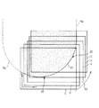
図1は、本発明の一実施形態に係る工具寸法の測定装置を備えた工作機械10の構成を概略的に示す図である。この工作機械10は、ワーク(図示されず)に加工処理を実行する機械部分に加え、工作機械10の動作を制御するNC装置12と、工作機械10及びNC装置12に接続されて工作機械10の工具の寸法を測定する寸法測定装置13と、を備える。工作機械10には例えば5軸立形のマシニングセンタが用いられる。本実施形態では、寸法測定装置13はNC装置12と別個に図示されているものの、寸法測定装置13は例えばNC装置12内に組み込まれてもよい。
Hereinafter, an embodiment of the present invention will be described with reference to the accompanying drawings.
FIG. 1 is a diagram schematically showing a configuration of a
まず、工作機械10の機械構成を説明する。工作機械10にはXYZ直交3軸の基準座標系が設定される。工作機械10は、水平面すなわちXY平面に沿って広がるベッド15と、ベッド15上に配置されたテーブルベース16と、テーブルベース16の後方でベッド15からZ軸に平行に垂直方向に立ち上がるコラム17と、を備える。テーブルベース16上にワーク(図示されず)が固定される。コラム17には主軸頭18が支持されている。主軸頭18の下端には主軸19を介して下向きに着脱自在に工具20が装着される。工具20は、主軸頭18内に組み込まれるスピンドルモータ(図示されず)により回転駆動される。ここでは、工具20には例えばボールエンドミルが用いられる。
First, the machine configuration of the
テーブルベース16は、直線送り機構を介して水平方向(X軸方向)に移動可能にベッド15上に支持されている。その一方で、主軸頭18は、直線送り機構を介して鉛直方向(Z軸方向)及び水平方向(Y軸方向)に移動可能にコラム17に支持されている。直線送り機構は、例えばボールねじと、このボールねじを回転駆動するサーボモータと、を備える。これらの直線送り機構によってテーブルベース16と主軸頭18すなわち工具20との相対移動が実現される。相対移動は、NC装置12から供給される後述の駆動信号に基づき実現される。相対移動中に回転する工具20が所定の加工点でワークに接触する。こうしてワークが所望の形状に加工される。
The
ベッド15には、当該ベッド15とテーブルベース16との間のX軸に沿った相対位置を読み取るX軸位置検出器21が組み込まれている。コラム17には、当該コラム17と主軸頭18との間のY軸及びZ軸に沿った相対位置をそれぞれ読み取るY軸位置検出器(図示されず)及びZ軸位置検出器22が組み込まれている。これらの位置検出器には例えばデジタルスケールが用いられればよい。これらの位置検出器で読み取られた相対位置は基準座標系の座標値で特定される。読み取られた座標値はNC装置12に出力すなわちフィードバックされる。
The
次に、NC装置12の構成を説明する。NC装置12は、NCプログラムを格納する記憶部24と、記憶部24に格納されているNCプログラムを解析するプログラム解析部25と、プログラム解析部25で解析されたNCプログラムに従って移動指令を生成する移動指令部26と、移動指令部26から出力された移動指令に従って工作機械10のサーボモータに駆動信号を出力するサーボ制御部27と、を備える。移動指令には、例えばワークの加工点の割り出しデータ及び割り出し後の加工点に対応した主軸頭18の位置を示す座標値データが含まれる。
Next, the configuration of the
次に、寸法測定装置13の構成を説明する。寸法測定装置13は、テーブルベース16上に配置される寸法測定ユニット31を備える。寸法測定ユニット31は、光源32と、光源32に向き合う撮像装置33と、を備える。光源32には撮像装置33に向かって平行光を出力する例えば高輝度LEDが用いられる。撮像装置33は例えば基準座標系のYZ平面内でテーブルベース16に対して相対移動することが可能である。撮像装置33はレンズユニット34及びCCD(電荷結合素子)イメージセンサ35を備える。CCDイメージセンサ35は例えば二次元イメージセンサを構成する。レンズユニット34は、例えば複数枚のレンズを備えており、レンズの駆動に基づき光学ズームによるズームイン及びズームアウトを実行する。
Next, the configuration of the
寸法測定装置13は、撮像装置33で撮像された画像の画像データの供給を受ける画像調整装置36と、光源32及び撮像装置33の動作を制御する制御装置37と、を備える。前述のCCDイメージセンサ35は、その受光面に結像される画像に対応してアナログの画像信号を生成する。画像信号は、所定の時間間隔ごとに設けられる各フレームに生成される。ここでは、例えば毎秒30〜60フレームの画像信号が出力される。画像信号は画素ごとの多階調輝度信号を特定する。画像信号はデジタル信号の画像データに変換されて画像調整装置36に出力される。
The
画像調整装置36は、画像データのシェーディング補正、ノイズリダクション、ホワイトバランス調整、輪郭補正及びコントラスト調整などの画像調整を実行する。画像調整された画像データでは画素ごとに明暗2値が特定される。画像調整装置36は、画像調整後の画像データを後述のフレームメモリに格納する。その一方で、制御装置37は、撮像装置33の移動やズームを制御する駆動信号を撮像装置33に出力する。なお、撮像装置33の視野には前述の基準座標系のYZ平面に対応してxy直交2軸の視野座標系が設定される。この視野座標系の各座標値は、YZ平面内における撮像装置33の移動後の各位置の視野ごとに基準座標系の各座標値に関連付けられる。
The
寸法測定装置13は、寸法測定プログラム及び工具寸法データを記憶する記憶装置41と、寸法測定プログラムに基づき様々な演算処理を実行する演算装置42と、フレームごとの画像データを格納するフレームメモリ43と、を備える。演算処理にあたって寸法測定プログラムは一時的にメモリ(図示されず)に読み出されればよい。寸法測定プログラム及び工具寸法データの詳細は後述される。なお、寸法測定プログラムは例えばFD(フレキシブルディスク)やCD−ROMその他の可搬性記録媒体から記憶装置41に取り込まれてもよく、LANやインターネットといったコンピューターネットワークから記憶装置41に取り込まれてもよい。
The
寸法測定装置13は、例えば工具20の像(シルエット)を表す画像データを構成する画素ごとの明暗2値の情報やその画素の座標値を表示する表示画面を有する表示装置44と、例えば表示画面上で所定の位置を指定することによって演算装置42に指示を入力する入力装置45と、を備える。表示装置44は例えばLCD(液晶ディスプレイ)パネルなどの平面ディスプレイパネルであればよく、入力装置45は例えばタッチパネルやキーボード、マウスなどであってよい。使用者は例えばタッチパネルやマウスを用いて、表示装置44の表示画面上に表示される画像上で工具20の輪郭線の方向を指定したり、工具20の輪郭線上の位置を指定したりすることができる。
The
次に、本発明に係る工作機械10の工具20の寸法を測定する方法を説明する。処理の実行にあたって寸法測定装置13の演算装置42は、記憶装置41から寸法測定プログラムを例えばメモリに一時的に読み出す。こうして演算装置42は寸法測定プログラムに基づき様々な演算処理を実行する。まず、演算装置42はNC装置12に開始信号を出力する。開始信号の受信に応じてNC装置12は、工作機械10に向かって駆動指令を出力する。その結果、工作機械10では、XY平面上で光源32及び撮像装置33の間の所定の基準位置に工具20の刃先部分が進入するように主軸19が位置決めされる。工具20はその回転中心回りに回転駆動される。主軸頭18すなわち工具20はZ軸に平行に下降させられる。ここで、基準位置とは、視野の中に予め設けられた、工具20の進入動作の停止を指示する基準となる位置のことである。
Next, a method for measuring the dimension of the
同時に、演算装置42は、光源32及び撮像装置33の動作を開始させる。制御装置37は、撮像装置33を駆動させる駆動信号を出力する。こうして撮像装置33は撮像を開始する。撮像装置33は撮像のフレームごとにアナログの画像信号を生成する。この画像信号から生成された画像データは画像調整装置36を介してフレームメモリ43にフレームごとに格納される。主軸頭18の下降に基づき工具20の輪郭の一部が撮像装置33の画像の視野内に進入すると、Z軸に沿った主軸頭18の下降は停止される。こうして基準位置の撮像装置33の画像の視野内には工具20の輪郭の一部が特定される。
At the same time, the
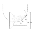
CCDイメージセンサ35の受光面には、光源32から照射される平行光によって工具20の影(シルエット)を投影した画像が結像される。画像データは、視野内の画像を特定する多数の画素から構成される。前述されるように、画像データでは画素ごとに明暗2値が特定されることから、例えば図2に示されるように、基準位置の画像データで特定される視野V内では、暗の画素は工具20の影の投影部分として特定される一方で、明の画素は平行光の受光部分として特定される。こうして工具20の一部の輪郭が特定される。
An image obtained by projecting the shadow (silhouette) of the
図3は、本発明の第1実施形態に係る工具20の寸法測定方法の処理の流れを示すフローチャートである。フレームメモリ43から読み出された基準位置の画像データに対して、ステップS1で、演算装置42は工具20の輪郭のエッジを検出する。前述のように各画素は明暗2値で示されることから、エッジは、画像の視野V中で工具20の画像の画素に対応する暗の画素のうち、明の画素に隣接する暗の画素で特定される。こうして図2から明らかなように、演算装置42は、ステップS2で、明の画素に隣接する連続した複数の暗の画素の抽出に基づき部分輪郭線51を特定する。
FIG. 3 is a flowchart showing a process flow of the dimension measuring method of the
前述のように、撮像装置33の視野内にはxy直交2軸の視野座標系が設定されることから、部分輪郭線51を構成する各画素の座標値が特定される。視野座標系の座標値は工作機械10の基準座標系に例えばキャリブレーションで予め関連付けられており、視野座標系の座標値は基準座標系の座標値に変換される。こうして基準座標系で部分輪郭線51の座標値が特定される。特定された部分輪郭線51の画像データはフレームメモリ43に格納される。部分輪郭線51の座標値を示す座標値データは画像データに関連付けてフレームメモリ43に格納されればよい。
As described above, an xy orthogonal biaxial visual field coordinate system is set in the visual field of the
その後、ステップS3で、演算装置42は部分輪郭線51の接線52を算出する。接線52は、部分輪郭線51上の座標値で例えば視野V内のx軸方向の中間位置の座標値を示す中間点で算出される。算出にあたって、例えば部分輪郭線51を構成する画素の座標値に基づいて部分輪郭線51を特定する数式が導き出される。この数式の微分に基づき接線52が算出される。また、数式の微分に代えて、部分輪郭線51を構成する任意の2点(例えば前述の中間点を含む)の画素から導き出される傾きから接線52が算出されてもよい。
Thereafter, in step S <b> 3, the
こうして算出された接線52に基づき、演算装置42は、ステップS4で、画像装置33の視野の移動方向53を決定する。具体的には、接線52で特定される正逆2方向が、この画像データの視野Vの視野外の輪郭線54の方向として推定される。ここでは、演算装置42は、接線52で特定される正逆2方向のうちの1方向(例えば右上方向)を撮像装置33の視野Vを移動させる移動方向53として設定する。演算装置42は、ステップS5で、移動方向53で特定される方向に視野Vを移動させる。演算装置42は、移動方向53に応じて工具20及び撮像装置33を相対移動させる移動信号を制御装置37に出力する。移動信号を受け取った制御装置37は、工具20及び撮像装置33を相対移動させるべく撮像装置33を移動させる。ここでは、撮像装置33はYZ平面内で移動させられる。撮像装置33の視野Vは移動方向53に沿って移動を開始する。
Based on the
撮像装置33及び工具20が相対移動を開始した後、演算装置42は1フレームごとの画像データに基づきステップS1〜ステップS5の処理を繰り返す。その結果、1フレームごとに視野Vの移動方向53が決定される。こうして、例えば図4に概念的に示されるように、各フレームごとに工具20の部分輪郭線51が特定されていく。前述の接線52に沿った一方の方向の複数の部分輪郭線51が所望の範囲にわたって特定されると、撮像装置33は最初の撮像位置に戻される。演算装置42は、接線52に沿った他方の方向(すなわち左下方向)に視野Vの移動方向53を設定する。この移動方向53に応じて工具20及び撮像装置33は相対移動する。こうして他方の方向における工具20の所望の範囲の複数の部分輪郭線51が特定される。なお、部分輪郭線51は工具20全体にわたって特定される必要はない。ここでは、工具20はボールエンドミルであることから、部分輪郭線51の特定はボールエンドミルのシャンクすなわち平行部分の輪郭線の一部が特定されるまで実行されればよい。
After the
演算装置42は、特定したすべての部分輪郭線51の画像データ及び座標値データをフレームメモリ43から読み出して、すべての部分輪郭線51を相互に結合して結合輪郭線55を形成する。結合にあたって例えば個々の部分輪郭線51の座標値データが用いられればよい。前述の通り、座標値データは基準座標系の座標値で特定される。こうして、図5から明らかなように、工具20の結合輪郭線55が抽出される。抽出された結合輪郭線55に基づき演算装置42は例えば工具20の刃先位置や工具径などを測定する。測定にあたって基準座標系の座標値が参照される。なお、結合輪郭線55や測定の結果は、例えば表示装置44の表示画面上に表示されてもよい。このとき、使用者が入力装置45を用いて表示画面上で工具20の特定の位置を指定して入力することにより、使用者が任意に工具20の測定位置を指定してもよい。
The
以上のように、第1実施形態に係る工作機械10によれば、撮像装置33の画像の視野V内に工具20全体の輪郭が収まらない場合(例えば0.6mm四方の視野で直径20mmのボールエンドミルを撮像する場合)、撮像装置33及び工具20の相対移動によって撮像装置33の視野Vは移動する。しかも、画像データから特定された部分輪郭線51に基づき1つの画像データの視野外の輪郭線54の方向に視野Vを移動させる移動方向53が決定されることから、撮像装置33は、視野Vの移動によって工具20の輪郭線を辿ることができる。こうして、撮像装置33の視野Vよりも大きな寸法の工具20の測定に際しても例えば所望の範囲にわたる複数の部分輪郭線51が特定される。例えば特定された複数の部分輪郭線51が結合されれば、工具20の所望の範囲の結合輪郭線55が抽出される。その結果、結合輪郭線55を用いて工具20の寸法が測定されることが可能である。
As described above, according to the
図5は、本発明の第2実施形態に係る工具20の寸法測定方法の処理の流れを示すフローチャートである。この実施形態では、前述のステップS1、S2と同様に、フレームメモリ43に格納された画像データが読み出され、ステップT1で工具20の輪郭のエッジが検出され、ステップT2で、連続した複数の暗の画素から部分輪郭線51が特定される。次に、ステップT3で、演算装置42は部分輪郭線51の回帰曲線Y=F(X)を算出する。回帰曲線の算出にあたって視野座標系における画素の座標値が参照されればよい。次に、ステップT4で、記憶装置41に格納された工具寸法データすなわち回帰曲線Y1=f1(X)、Y2=f2(X)〜Yn−1=fn-1(X)、Yn=fn(X)を参照して、算出された回帰曲線と一致する回帰曲線が検索される。なお、工具寸法データは、様々な工具20ごとに予め測定された工具20の輪郭線の回帰曲線である。
FIG. 5 is a flowchart showing a process flow of the dimension measuring method of the
算出された回帰曲線Y=F(X)に一致する回帰曲線Yn=fn(X)が特定されると、ステップT5で演算装置42は、例えば図6に示されるように、一致した回帰曲線Yn=fn(X)を画像データ上の回帰曲線Y=F(X)に重ね合わせる。次に、ステップT6で演算装置42は、一致した回帰曲線Yn=fn(X)のY切片などの実値を特定して視野座標系の座標値に変換する。こうしてこの画像データの視野外の輪郭線54の方向が特定される。ステップT7で、演算装置42は、特定された輪郭線54の方向に基づき画像装置33の視野Vの移動方向53を決定する。決定にあたって、演算装置42は、回帰曲線Yn=fn(X)で特定される視野外の輪郭線54に沿った正逆2方向のうちの例えば1方向を移動方向53として特定する。演算装置42は、ステップT8で、特定された移動方向53に視野Vを移動させる。ここでは、視野V上で例えば右上の方向が選択される。
When the regression curve Yn = f n (X) that matches the calculated regression curve Y = F (X) is specified, the
前述と同様に、演算装置42から出力される移動信号に基づき、撮像装置33の視野Vは移動方向53に移動する。演算装置42は1フレームごとにステップT1〜ステップT8の処理を繰り返す。従って、1フレームごとに撮像装置33の視野Vの移動方向53が決定される。前述の輪郭線54の一方の方向の部分輪郭線51が所望の範囲にわたって特定されると、演算装置42は、輪郭線54の他方の方向(例えば視野Vの左方向)に視野を移動させるべく撮像装置33を最初の撮像位置に戻す。演算装置42は、他方の方向に視野Vの移動方向53を設定する。この移動方向53に応じて工具20及び撮像装置33は相対移動する。こうして他方の方向における工具20の所望の範囲の複数の部分輪郭線51が特定される。その後は前述と同様の処理が実行される。なお、視野Vの移動方向53の決定にあたって撮像装置33の視野V内において工具20の影が占める占有面積が用いられてもよい。
As described above, the visual field V of the
図7は、本発明の第3実施形態に係る工具20の寸法測定方法の処理の流れを示すフローチャートである。この実施形態では、前述のステップS1、S2と同様に、フレームメモリ43に格納された画像データが読み出され、ステップU1で工具20の輪郭のエッジが検出される。ステップU2で、連続した複数の暗の画素から部分輪郭線51が特定される。その後、ステップU3で、演算装置42は、撮像装置33にズームアウトを実行させる指令信号を制御装置37に出力する。制御装置37はレンズユニット34の駆動に基づきズームアウトを実行する。その結果、図8に示されるように、撮像装置33の視野Vが拡大する。
FIG. 7 is a flowchart showing a process flow of the dimension measuring method for the
ステップU4で、演算装置42は、視野の拡大した画像データに基づき部分輪郭線51を除く工具20の概略輪郭線56を特定する。特定にあたって前述の部分輪郭線51を特定する際の手法が用いられる。演算装置42は、ステップU5で、特定した概略輪郭線56に基づき演算装置42は画像装置33の視野Vの移動方向53を決定する。決定にあたって、演算装置42は、概略輪郭線56で特定される正逆2方向のうちの一方の方向を、工具20と撮像装置33とを相対移動させる移動方向53として設定する。ここでは、例えば特定された概略輪郭線56の長さに基づき、次にズームアウトする時までの工具20と撮像装置33との相対移動の距離が特定されればよい。
In step U <b> 4, the
演算装置42は、ステップU6で、指令信号の出力に基づき、前述の最初に部分輪郭線51を特定した視野Vの大きさまで撮像装置33をズームインさせる。その後、演算装置42は、ステップU7で、概略輪郭線56で特定されるいずれかの方向に視野Vを移動させる。ここでは、視野V上で例えば右上の方向の移動方向53が選択される。演算装置42は、工具20と撮像装置33とを相対移動させる移動信号を撮像装置33に出力する。こうして前述と同様に、工具20及び撮像装置33は相対移動する。相対移動中、演算装置42は、フレームメモリ43から読み出される画像データに基づき各フレームごとに部分輪郭線51を特定していく。
In step U6, the
最初に特定された相対移動の距離を工具20が移動する間、ステップU8で、部分輪郭線51の特定が繰り返される。その後、相対移動の距離を工具20が移動し終わると、演算装置42はステップU3〜U8の処理を繰り返す。前述の輪郭線53の一方の方向の複数の部分輪郭線51が所望の範囲にわたって特定されると、演算装置42は、最初に特定された概略輪郭線56で特定される2方向のうちの他方の方向(すなわち左方向)に視野Vを移動させるべく撮像装置33を最初の撮像位置まで戻す。演算装置42は、他方の方向に視野Vの移動方向53を設定する。この移動方向53に応じて工具20及び撮像装置33は相対移動する。こうして工具20の所望の範囲にわたって複数の部分輪郭線51が特定される。その後は前述と同様の処理が実行される。
While the
本実施形態に係る工作機械10によれば、撮像装置33の画像の視野V内に工具20の輪郭の全体が収まらない場合、撮像装置33及び工具20の相対移動によって画像の視野Vは移動する。移動に先立って、ズームアウトによって最初の画像の視野Vに比べて視野が拡大することから、視野外の輪郭線53の方向が確実に認識されることが可能である。その結果、撮像装置33は、視野Vの移動によって輪郭線53を辿ることができる。しかも、ズームインによって最初の画像の視野Vが再び実現されることから、工具20の部分輪郭線51を高精度に特定することができる。こうして特定された複数の部分輪郭線51が結合されれば、工具20の所望の範囲の結合輪郭線55が抽出される。その結果、結合輪郭線55を用いて工具20の寸法が測定されることが可能である。
According to the
なお、第2実施形態に係る工具寸法の測定方法では、画像データ内の画素数は一定である一方でズームアウトによって視野Vが拡大することから、各画素で特定される撮像範囲が拡大される。従って、ズームアウト時に撮像される工具20の概略輪郭線56は工具20の形状を概略的に特定するに過ぎない。従って、工具20の輪郭の高精度の抽出にあたって概略輪郭線56を用いることは得策ではないと考えられる。
In the tool dimension measuring method according to the second embodiment, since the field of view V is expanded by zooming out while the number of pixels in the image data is constant, the imaging range specified by each pixel is expanded. . Therefore, the
その他、ズームアウト時の画像が例えば表示装置44の表示画面に表示されてもよい。使用者は、例えば入力装置45を用いて表示画面上で視野Vの移動方向53を具体的に特定すべく指示を入力してもよい。このとき、演算装置42は、入力装置45によって入力された指示に応じて視野Vの移動方向53を特定すればよい。その他、上述の実施形態では、レンズユニット34の駆動に基づき光学ズームによって撮像装置33のズームイン及びズームアウトが実現されたものの、例えばデジタルズームによってズームイン及びズームアウトが実現されてもよい。
In addition, an image at the time of zooming out may be displayed on the display screen of the display device 44, for example. The user may input an instruction to specifically specify the moving
以上のような実施形態では、工作機械10の例として立形のマシニングセンタを用いて本発明の工具寸法の測定方法及び測定装置が説明されたものの、本発明の工具寸法の測定方法及び測定装置は、例えば横形のマシニングセンタやその他の工作機械によっても実現されることが可能である。また、工具20の例としてボールエンドミルを用いて本発明の工具寸法の測定方法及び測定装置が説明されたものの、本発明の工具寸法の測定方法及び測定装置は、例えばフラットエンドミルやドリル等、その他の工具によっても実現されることが可能である。また、工作機械10では、主軸頭18のY軸方向の移動に代えてテーブルベース16がY軸方向に移動してもよい。その他、撮像装置33と工具20との相対移動の実現にあたって撮像装置33に対して工具20が移動してもよい。
In the above embodiment, although the tool dimension measuring method and measuring apparatus of the present invention have been described using a vertical machining center as an example of the
10 工作機械
13 寸法測定装置
20 工具
33 撮像装置
42 演算装置
44 表示装置
45 入力装置
51 部分輪郭線(部分輪郭)
53 移動方向
54 輪郭線(輪郭)
55 結合輪郭線(結合輪郭)
56 概略輪郭線(概略輪郭)
DESCRIPTION OF
53
55 Joining contour (joint contour)
56 Outline (Outline outline)
Claims (3)
前記撮像装置によって前記工具の輪郭の一部を撮像した画像データに基づき前記工具の部分輪郭を特定し、構成する各画素の座標値を特定し、予め関連付けられた基準座標系の座標値に変換し、基準座標系で部分輪郭の座標値を特定する工程と、
部分輪郭線を構成する画素の座標値に基づいて特定した前記部分輪郭の前記撮像装置の視野内での接線を算出し、該接線の方向を前記画像データの視野外の前記工具の輪郭の方向に前記撮像装置の視野を移動させる移動方向として決定する工程と、
決定した前記視野の移動方向に前記撮像装置の視野が移動するように前記撮像装置と前記工具とを相対移動させる移動指令を工作機械の制御装置に出力する工程と、
前記部分輪郭の特定、前記視野の移動方向の決定、並びに前記撮像装置と前記工具との相対移動の移動指令の出力の各工程を順次繰り返して得た複数の前記画像データ及び基準座標系の座標値で特定できる座標値データの各々に基づき特定した前記部分輪郭を相互に結合して、前記工具の結合輪郭を抽出する工程と、
を備え、前記工具の結合輪郭を用いて前記工具の寸法を測定することを特徴とする工具寸法の測定方法。 In the measurement method of the tool dimension, the tool is imaged using an imaging device that moves relative to the tool, and the dimension of the tool is measured based on the obtained image data.
The partial contour of the tool is identified based on image data obtained by imaging a part of the contour of the tool by the imaging device, the coordinate value of each constituent pixel is identified, and the coordinate value is converted into a coordinate value of a reference coordinate system associated in advance. And specifying the coordinate value of the partial contour in the reference coordinate system,
A tangent line in the field of view of the imaging device of the partial contour specified based on the coordinate value of a pixel constituting the partial contour line is calculated, and the direction of the tangent line is the direction of the contour of the tool outside the field of view of the image data Determining the moving direction to move the field of view of the imaging device;
Outputting a movement command for moving the imaging device and the tool relative to each other so that the visual field of the imaging device moves in the determined movement direction of the visual field to a control device of a machine tool;
The plurality of image data and coordinates of the reference coordinate system obtained by sequentially repeating the steps of specifying the partial contour, determining the moving direction of the visual field, and outputting a movement command for relative movement between the imaging device and the tool Combining the partial contours identified based on each of the coordinate value data that can be identified by values to extract the joint contour of the tool;
And measuring the dimension of the tool using the joint contour of the tool.
前記工具を撮像して画像データを生成する撮像装置と、
生成した前記画像データに基づき前記工具の輪郭の一部を形成する部分輪郭を特定し、構成する各画素の座標値を特定し、予め関連付けられた基準座標系の座標値に変換し、基準座標系で部分輪郭の座標値を特定し、特定した前記部分輪郭の前記撮像装置の視野内での接線を算出し、該接線の方向を前記画像データの視野外の前記工具の輪郭の方向に前記撮像装置の視野を移動させる移動方向として決定し、決定した前記視野の移動方向に前記撮像装置の視野が移動するように前記撮像装置と前記工具とを相対移動させる移動指令を工作機械の制御装置に出力し、前記部分輪郭の特定、前記視野の移動方向の決定、並びに前記撮像装置と前記工具との相対移動の移動指令の出力の各工程を順次繰り返して得た複数の前記画像データ及び基準座標系の座標値で特定できる座標値データの各々に基づき特定した前記部分輪郭を相互に結合して、前記工具の結合輪郭を抽出する演算装置と、
を備え、前記工具の結合輪郭を用いて前記工具の寸法を測定することを特徴とする工具寸法の測定装置。 In a tool size measuring device for measuring the size of the tool from image data obtained by imaging the tool,
An imaging device that images the tool and generates image data;
Based on the generated image data, a partial contour that forms a part of the contour of the tool is specified, the coordinate value of each pixel that is configured is specified, converted into a coordinate value of a reference coordinate system that is associated in advance, and a reference coordinate The coordinate value of the partial contour is specified by the system, the tangent line in the field of view of the imaging device of the specified partial contour is calculated, and the direction of the tangent line is set in the direction of the contour of the tool outside the field of view of the image data. A control device for a machine tool that determines a movement direction for moving the field of view of the imaging device and moves the imaging device and the tool relative to each other so that the field of view of the imaging device moves in the determined movement direction of the field of view. A plurality of the image data and the reference obtained by sequentially repeating the steps of specifying the partial contour, determining the moving direction of the visual field, and outputting a movement command for relative movement between the imaging device and the tool. seat The partial contour specified on the basis of each of the coordinate value data can be specified by the coordinate values of the system are bonded to each other, an arithmetic unit for extracting the coupling contour of said tool,
And measuring the dimension of the tool by using the joint contour of the tool.
Priority Applications (1)
| Application Number | Priority Date | Filing Date | Title |
|---|---|---|---|
| JP2016076180A JP6147389B2 (en) | 2016-04-05 | 2016-04-05 | Tool dimension measuring device |
Applications Claiming Priority (1)
| Application Number | Priority Date | Filing Date | Title |
|---|---|---|---|
| JP2016076180A JP6147389B2 (en) | 2016-04-05 | 2016-04-05 | Tool dimension measuring device |
Related Parent Applications (1)
| Application Number | Title | Priority Date | Filing Date |
|---|---|---|---|
| JP2010241331A Division JP2012091288A (en) | 2010-10-22 | 2010-10-27 | Method and device for measuring tool dimension |
Publications (2)
| Publication Number | Publication Date |
|---|---|
| JP2016166877A true JP2016166877A (en) | 2016-09-15 |
| JP6147389B2 JP6147389B2 (en) | 2017-06-14 |
Family
ID=56897666
Family Applications (1)
| Application Number | Title | Priority Date | Filing Date |
|---|---|---|---|
| JP2016076180A Active JP6147389B2 (en) | 2016-04-05 | 2016-04-05 | Tool dimension measuring device |
Country Status (1)
| Country | Link |
|---|---|
| JP (1) | JP6147389B2 (en) |
Cited By (4)
| Publication number | Priority date | Publication date | Assignee | Title |
|---|---|---|---|---|
| JP2020533193A (en) * | 2017-09-13 | 2020-11-19 | レニショウ パブリック リミテッド カンパニーRenishaw Public Limited Company | Non-contact tool setting device and method |
| JP6946584B1 (en) * | 2021-02-15 | 2021-10-06 | Dmg森精機株式会社 | Image processing equipment and machine tools |
| KR20220000896A (en) * | 2020-06-22 | 2022-01-04 | 주식회사 히타치하이테크 | Dimension measuring device, semiconductor manufacturing device and semiconductor device manufacturing system |
| CN114623780A (en) * | 2022-01-26 | 2022-06-14 | 深圳职业技术学院 | Detection device and online detection method for three-dimensional reconstruction of tool nose |
Families Citing this family (1)
| Publication number | Priority date | Publication date | Assignee | Title |
|---|---|---|---|---|
| FR3068457B1 (en) * | 2017-06-30 | 2019-08-16 | Lectra | METHOD FOR DETERMINING A DIMENSION BETWEEN THE BACK AND THE SHARP WIRE OF A VIBRATING BLADE MOUNTED ON A CUTTING TOOL |
Citations (5)
| Publication number | Priority date | Publication date | Assignee | Title |
|---|---|---|---|---|
| JPH0241856A (en) * | 1988-07-28 | 1990-02-13 | Toyoda Mach Works Ltd | Machine tool equipped with cutting tool shape measuring function |
| JPH09101125A (en) * | 1995-10-07 | 1997-04-15 | Kawasaki Heavy Ind Ltd | Article shape measuring method and apparatus |
| JPH11118444A (en) * | 1997-10-14 | 1999-04-30 | Mitsutoyo Corp | Non-contact image measuring system |
| US20010017699A1 (en) * | 2000-01-08 | 2001-08-30 | Joachim Egelhof | Method and measuring device for measuring a rotary tool |
| DE10153581A1 (en) * | 2001-11-02 | 2003-05-15 | Heilig & Schwab Gmbh | Determining effective contour of rotary machine tool in adjusting apparatus, by measuring maximum excursion of shadow boundary line from tool axis at certain points |
-
2016
- 2016-04-05 JP JP2016076180A patent/JP6147389B2/en active Active
Patent Citations (5)
| Publication number | Priority date | Publication date | Assignee | Title |
|---|---|---|---|---|
| JPH0241856A (en) * | 1988-07-28 | 1990-02-13 | Toyoda Mach Works Ltd | Machine tool equipped with cutting tool shape measuring function |
| JPH09101125A (en) * | 1995-10-07 | 1997-04-15 | Kawasaki Heavy Ind Ltd | Article shape measuring method and apparatus |
| JPH11118444A (en) * | 1997-10-14 | 1999-04-30 | Mitsutoyo Corp | Non-contact image measuring system |
| US20010017699A1 (en) * | 2000-01-08 | 2001-08-30 | Joachim Egelhof | Method and measuring device for measuring a rotary tool |
| DE10153581A1 (en) * | 2001-11-02 | 2003-05-15 | Heilig & Schwab Gmbh | Determining effective contour of rotary machine tool in adjusting apparatus, by measuring maximum excursion of shadow boundary line from tool axis at certain points |
Cited By (8)
| Publication number | Priority date | Publication date | Assignee | Title |
|---|---|---|---|---|
| JP2020533193A (en) * | 2017-09-13 | 2020-11-19 | レニショウ パブリック リミテッド カンパニーRenishaw Public Limited Company | Non-contact tool setting device and method |
| JP7524055B2 (en) | 2017-09-13 | 2024-07-29 | レニショウ パブリック リミテッド カンパニー | NON-CONTACT TOOL SETTING APPARATUS AND METHOD |
| KR20220000896A (en) * | 2020-06-22 | 2022-01-04 | 주식회사 히타치하이테크 | Dimension measuring device, semiconductor manufacturing device and semiconductor device manufacturing system |
| KR102659861B1 (en) | 2020-06-22 | 2024-04-24 | 주식회사 히타치하이테크 | Dimension measurement equipment, semiconductor manufacturing equipment and semiconductor device manufacturing systems |
| JP6946584B1 (en) * | 2021-02-15 | 2021-10-06 | Dmg森精機株式会社 | Image processing equipment and machine tools |
| WO2022172662A1 (en) * | 2021-02-15 | 2022-08-18 | Dmg森精機株式会社 | Image processing device and machine tool |
| JP2022123922A (en) * | 2021-02-15 | 2022-08-25 | Dmg森精機株式会社 | Image processing equipment and machine tools |
| CN114623780A (en) * | 2022-01-26 | 2022-06-14 | 深圳职业技术学院 | Detection device and online detection method for three-dimensional reconstruction of tool nose |
Also Published As
| Publication number | Publication date |
|---|---|
| JP6147389B2 (en) | 2017-06-14 |
Similar Documents
| Publication | Publication Date | Title |
|---|---|---|
| JP5725796B2 (en) | Tool measuring method and measuring device, and machine tool | |
| JP5832083B2 (en) | Tool dimension measuring method and measuring device | |
| CN103180094B (en) | The assay method of tool sizes and determinator | |
| JP6147389B2 (en) | Tool dimension measuring device | |
| JP2009175954A (en) | Generating device of processing robot program | |
| CN108732994B (en) | Control system for machine tool | |
| JPWO2008026723A1 (en) | 3D model data confirmation method and 3D model data confirmation apparatus | |
| JP2001319219A (en) | Device and method for generating part program for image measuring apparatus, image measuring apparatus and measure result display method therefor | |
| JP6250896B2 (en) | Waveform display device that converts vibration period to length on machined surface and displays it | |
| JP2018151965A (en) | Control system for machine tool | |
| JP2012091288A (en) | Method and device for measuring tool dimension | |
| JP7120894B2 (en) | 3D model creation device, machining simulation device, automatic tool path generation device | |
| TW202303089A (en) | Processing method and processing device for generating cross-sectional image from three-dimensional position information acquired by visual sensor | |
| JP3215193B2 (en) | Method and apparatus for measuring blade shape of rotary tool | |
| JP2016040531A (en) | Working tool measuring method and measuring device | |
| KR100679550B1 (en) | Fault detector and fault detection method | |
| CN108732998B (en) | Control system for machine tool | |
| JP3958815B2 (en) | Tool position measuring method in NC machine tools | |
| JP2011093004A (en) | Nc grinding device having on-board image measuring system | |
| JP6946584B1 (en) | Image processing equipment and machine tools | |
| JP2017222028A (en) | Waveform display device for displaying by converting vibration period into length on processing surface | |
| JP2003203216A (en) | Image measuring device part program generating device and image forming device part program generating program | |
| JP5577508B2 (en) | Image measuring apparatus and drive control method thereof | |
| JPH1163953A (en) | Image measuring device and its image displaying method | |
| JP3853500B2 (en) | Edge detection method and image measuring apparatus |
Legal Events
| Date | Code | Title | Description |
|---|---|---|---|
| TRDD | Decision of grant or rejection written | ||
| A01 | Written decision to grant a patent or to grant a registration (utility model) |
Free format text: JAPANESE INTERMEDIATE CODE: A01 Effective date: 20170418 |
|
| A61 | First payment of annual fees (during grant procedure) |
Free format text: JAPANESE INTERMEDIATE CODE: A61 Effective date: 20170516 |
|
| R150 | Certificate of patent or registration of utility model |
Ref document number: 6147389 Country of ref document: JP Free format text: JAPANESE INTERMEDIATE CODE: R150 |