JP2016166741A - Magnetic sensor - Google Patents
Magnetic sensor Download PDFInfo
- Publication number
- JP2016166741A JP2016166741A JP2015045477A JP2015045477A JP2016166741A JP 2016166741 A JP2016166741 A JP 2016166741A JP 2015045477 A JP2015045477 A JP 2015045477A JP 2015045477 A JP2015045477 A JP 2015045477A JP 2016166741 A JP2016166741 A JP 2016166741A
- Authority
- JP
- Japan
- Prior art keywords
- magnetic field
- component
- angle
- value
- ratio
- Prior art date
- Legal status (The legal status is an assumption and is not a legal conclusion. Google has not performed a legal analysis and makes no representation as to the accuracy of the status listed.)
- Granted
Links
Images


Classifications
-
- G—PHYSICS
- G01—MEASURING; TESTING
- G01D—MEASURING NOT SPECIALLY ADAPTED FOR A SPECIFIC VARIABLE; ARRANGEMENTS FOR MEASURING TWO OR MORE VARIABLES NOT COVERED IN A SINGLE OTHER SUBCLASS; TARIFF METERING APPARATUS; MEASURING OR TESTING NOT OTHERWISE PROVIDED FOR
- G01D5/00—Mechanical means for transferring the output of a sensing member; Means for converting the output of a sensing member to another variable where the form or nature of the sensing member does not constrain the means for converting; Transducers not specially adapted for a specific variable
- G01D5/12—Mechanical means for transferring the output of a sensing member; Means for converting the output of a sensing member to another variable where the form or nature of the sensing member does not constrain the means for converting; Transducers not specially adapted for a specific variable using electric or magnetic means
- G01D5/14—Mechanical means for transferring the output of a sensing member; Means for converting the output of a sensing member to another variable where the form or nature of the sensing member does not constrain the means for converting; Transducers not specially adapted for a specific variable using electric or magnetic means influencing the magnitude of a current or voltage
- G01D5/142—Mechanical means for transferring the output of a sensing member; Means for converting the output of a sensing member to another variable where the form or nature of the sensing member does not constrain the means for converting; Transducers not specially adapted for a specific variable using electric or magnetic means influencing the magnitude of a current or voltage using Hall-effect devices
- G01D5/145—Mechanical means for transferring the output of a sensing member; Means for converting the output of a sensing member to another variable where the form or nature of the sensing member does not constrain the means for converting; Transducers not specially adapted for a specific variable using electric or magnetic means influencing the magnitude of a current or voltage using Hall-effect devices influenced by the relative movement between the Hall device and magnetic fields
-
- G—PHYSICS
- G01—MEASURING; TESTING
- G01R—MEASURING ELECTRIC VARIABLES; MEASURING MAGNETIC VARIABLES
- G01R33/00—Arrangements or instruments for measuring magnetic variables
- G01R33/02—Measuring direction or magnitude of magnetic fields or magnetic flux
- G01R33/06—Measuring direction or magnitude of magnetic fields or magnetic flux using galvano-magnetic devices
- G01R33/09—Magnetoresistive devices
- G01R33/093—Magnetoresistive devices using multilayer structures, e.g. giant magnetoresistance sensors
Abstract
Description
本発明は、被検出磁界の方向が基準方向に対してなす角度を検出するための磁気センサに関する。 The present invention relates to a magnetic sensor for detecting an angle formed by a direction of a detected magnetic field with respect to a reference direction.
近年、自動車のステアリングの回転位置の検出等の種々の用途で、対象物の回転位置を検出するために、磁気センサが広く利用されている。磁気センサは、対象物の回転位置を検出する場合に限らず、対象物の直線的な変位を検出する場合にも利用されている。磁気センサが用いられるシステムでは、一般的に、対象物の回転や直線的な運動に連動して方向が回転する被検出磁界を発生する磁界発生部が設けられる。磁界発生部は、例えば磁石である。磁気センサは、磁気検出素子を用いて、基準位置における被検出磁界の方向が基準方向に対してなす角度を検出する。これにより、対象物の回転位置や直線的な変位が検出される。 In recent years, magnetic sensors have been widely used to detect the rotational position of an object in various applications such as detection of the rotational position of an automobile steering. Magnetic sensors are used not only when detecting the rotational position of an object, but also when detecting a linear displacement of the object. In a system in which a magnetic sensor is used, a magnetic field generator that generates a detected magnetic field whose direction rotates in conjunction with the rotation or linear motion of an object is generally provided. The magnetic field generator is, for example, a magnet. The magnetic sensor uses a magnetic detection element to detect an angle formed by the direction of the detected magnetic field at the reference position with respect to the reference direction. As a result, the rotational position and linear displacement of the object are detected.
磁気センサとしては、特許文献1および2に記載されているように、2つのブリッジ回路(ホイートストンブリッジ回路)を有するものが知られている。この磁気センサにおいて、2つのブリッジ回路は、それぞれ、4つの磁気検出素子を含み、被検出磁界の方向に対応した信号を出力する。磁気検出素子は、磁気抵抗効果素子(以下、MR素子とも記す。)を含む。2つのブリッジ回路の出力信号の位相は、各ブリッジ回路の出力信号の周期の1/4だけ異なっている。被検出磁界の方向が基準方向に対してなす角度は、2つのブリッジ回路の出力信号に基づいて算出される。
As described in
MR素子を用いた磁気センサでは、被検出磁界の方向の回転に伴って、MR素子の抵抗値に対応するMR素子の出力信号の波形は、理想的には正弦曲線(サイン(Sine)波形とコサイン(Cosine)波形を含む)となる。しかし、特許文献1に記載されているように、MR素子の出力信号波形は正弦曲線から歪む場合があることが知られている。MR素子の出力信号波形が正弦曲線から歪むということは、MR素子の出力信号が、正弦曲線の基本波以外の高調波成分を含むということである。MR素子の出力信号が高調波成分を含んでいると、磁気センサによる検出角度に誤差が生じる場合がある。
In the magnetic sensor using the MR element, the waveform of the output signal of the MR element corresponding to the resistance value of the MR element is ideally a sine curve (Sine waveform) as the direction of the detected magnetic field rotates. Cosine waveform). However, as described in
以下、MR素子が、磁化方向が固定された磁化固定層と、被検出磁界の方向に応じて磁化の方向が変化する自由層と、磁化固定層と自由層の間に配置された非磁性層とを有するスピンバルブ型MR素子である場合を例にとって、MR素子の出力信号波形が歪む場合の例について説明する。スピンバルブ型MR素子としては、例えばGMR(巨大磁気抵抗効果)素子やTMR(トンネル磁気抵抗効果)素子がある。MR素子の出力信号波形が歪む場合の例としては、磁化固定層の磁化方向が被検出磁界等の影響によって変動する場合や、自由層の磁化方向が、自由層の形状異方性等の影響によって、被検出磁界の方向と一致しない場合が挙げられる。 Hereinafter, the MR element includes a magnetization fixed layer whose magnetization direction is fixed, a free layer whose magnetization direction changes according to the direction of the detected magnetic field, and a nonmagnetic layer disposed between the magnetization fixed layer and the free layer An example of a case where the output signal waveform of the MR element is distorted will be described, taking as an example the case of a spin valve MR element having the above. Examples of the spin valve MR element include a GMR (giant magnetoresistive effect) element and a TMR (tunnel magnetoresistive effect) element. Examples of the case where the output signal waveform of the MR element is distorted include the case where the magnetization direction of the magnetization fixed layer fluctuates due to the influence of the detected magnetic field or the like, or the magnetization direction of the free layer is influenced by the shape anisotropy of the free layer, etc. Depending on the case, the direction of the detected magnetic field may not match.
特許文献1には、以下のようにして検出角度の誤差を低減する技術が記載されている。この技術では、従来のブリッジ回路を構成するスピンバルブ型MR素子を、直列に接続された複数のスピンバルブ型MR素子よりなるMR素子列に置き換えて、ブリッジ回路を構成する。MR素子列は、MR素子の対を1つ以上含む。対を構成する2つのMR素子における磁化固定層の磁化方向は、従来のブリッジ回路を構成するMR素子における磁化固定層の磁化方向を基準として、互いに反対方向に同じ角度だけ回転させた方向である。
特許文献2には、主参照磁化軸を持つ主検出素子に、それぞれ主参照磁化軸に対して傾いた参照磁化軸を有する2つの補正検出素子を電気的に接続して、検出角度を補正する技術が記載されている。
In
ところで、本願の発明者による研究の課程で、磁気センサでは、検出角度の誤差が被検出磁界の強度に応じて変化することが分かった。以下、検出角度の誤差を角度誤差と言い、角度誤差が被検出磁界の強度に応じて変化することを角度誤差の磁界強度依存と言う。この角度誤差の磁界強度依存は、検出角度の誤差を低減する手段を講じた磁気センサにも存在していた。 By the way, in the course of research by the inventors of the present application, it has been found that in the magnetic sensor, the error in the detection angle changes according to the strength of the detected magnetic field. Hereinafter, the error of the detected angle is referred to as an angle error, and the change of the angle error according to the strength of the detected magnetic field is referred to as the dependence of the angle error on the magnetic field strength. The dependence of the angle error on the magnetic field strength also exists in a magnetic sensor provided with a means for reducing the error in the detection angle.
一方、磁気センサが用いられるシステムでは、磁気センサに印加される被検出磁界の強度が一定とは限らない。例えば、同じ磁気センサに対して、被検出磁界の強度が異なる複数種類の磁界発生部を組み合わせることが可能である。また、磁界発生部として磁石を用いた場合、磁石を変えなくても、磁石の温度変化や劣化によって被検出磁界の強度が変化する可能性がある。また、安価な磁石を用いた場合等において、実際の被検出磁界の強度が、システム設計段階で想定した強度と異なる可能性がある。 On the other hand, in a system using a magnetic sensor, the intensity of the detected magnetic field applied to the magnetic sensor is not always constant. For example, it is possible to combine a plurality of types of magnetic field generators having different detected magnetic field strengths with the same magnetic sensor. Further, when a magnet is used as the magnetic field generator, the strength of the detected magnetic field may change due to temperature change or deterioration of the magnet without changing the magnet. In addition, when an inexpensive magnet is used, the actual detected magnetic field strength may be different from the strength assumed in the system design stage.
従来の磁気センサでは、前述の角度誤差の磁界強度依存に起因して、磁気センサの使用時の被検出磁界の強度の範囲として想定される所定の範囲内において角度誤差の変動量が大きくなる場合があった。この場合、従来の磁気センサでは、被検出磁界の強度が上記所定の範囲内の特定の値のときに角度誤差が低減されるように検出角度の補正処理を行っても、被検出磁界の強度が上記特定の値と異なるときには、角度誤差が十分に低減されないという問題点があった。 In conventional magnetic sensors, due to the above-mentioned dependence of the angle error on the magnetic field strength, the amount of fluctuation of the angle error is large within a predetermined range assumed as the range of the detected magnetic field strength when using the magnetic sensor. was there. In this case, in the conventional magnetic sensor, even if the detection angle is corrected so that the angle error is reduced when the intensity of the detected magnetic field is a specific value within the predetermined range, the intensity of the detected magnetic field When is different from the above specific value, there is a problem that the angle error is not sufficiently reduced.
本発明はかかる問題点に鑑みてなされたもので、その目的は、被検出磁界の方向が基準方向に対してなす角度を検出するための磁気センサであって、被検出磁界の強度の広い範囲で、検出角度の誤差の変動量が小さい磁気センサを提供することにある。 The present invention has been made in view of such problems, and an object of the present invention is a magnetic sensor for detecting an angle formed by the direction of a detected magnetic field with respect to a reference direction, and a wide range of the intensity of the detected magnetic field. Thus, it is an object of the present invention to provide a magnetic sensor with a small variation in detection angle error.
本発明の磁気センサは、基準位置における被検出磁界の方向が基準方向に対してなす角度と対応関係を有する角度検出値を生成するものであって、磁界検出部と演算部とを備えている。磁界検出部は、被検出磁界を検出する複数の磁気抵抗効果素子を含み、被検出磁界の方向が第1の方向に対してなす角度と対応関係を有する第1の信号と被検出磁界の方向が第2の方向に対してなす角度と対応関係を有する第2の信号とを出力する。複数の磁気抵抗効果素子の各々は、磁化方向が固定された磁化固定層と、被検出磁界の方向に応じて磁化の方向が変化する自由層と、磁化固定層と自由層の間に配置された非磁性層とを有している。演算部は、第1および第2の信号に基づいて角度検出値を算出する。 The magnetic sensor of the present invention generates an angle detection value having a correspondence relationship with the angle formed by the direction of the detected magnetic field at the reference position with respect to the reference direction, and includes a magnetic field detection unit and a calculation unit. . The magnetic field detection unit includes a plurality of magnetoresistive elements that detect the detected magnetic field, and the direction of the detected signal and the first signal having a correspondence relationship with the angle formed by the direction of the detected magnetic field with respect to the first direction Outputs a second signal having a corresponding relationship with the angle formed by the second direction. Each of the plurality of magnetoresistive elements is disposed between a magnetization fixed layer whose magnetization direction is fixed, a free layer whose magnetization direction changes according to the direction of the detected magnetic field, and between the magnetization fixed layer and the free layer. And a nonmagnetic layer. The calculation unit calculates an angle detection value based on the first and second signals.
本発明の磁気センサにおいて、被検出磁界の方向が所定の周期で回転する場合、角度検出値は、所定の周期の1/4の周期で変化する角度誤差成分を含む。本発明の磁気センサは、磁界検出部における被検出磁界の強度が、20〜150mTの範囲の一部である副範囲であって、上限と下限の差が30mT以上である副範囲内で変化するときの角度誤差成分の絶対値の最大値の変動量が0.1°以下であるものである。 In the magnetic sensor of the present invention, when the direction of the detected magnetic field rotates at a predetermined cycle, the angle detection value includes an angle error component that changes at a quarter of the predetermined cycle. In the magnetic sensor of the present invention, the intensity of the magnetic field to be detected in the magnetic field detector is a sub-range that is part of the range of 20 to 150 mT, and changes within the sub-range in which the difference between the upper limit and the lower limit is 30 mT or more. The fluctuation amount of the absolute value of the absolute value of the angle error component is 0.1 ° or less.
本発明の磁気センサにおいて、被検出磁界の方向が所定の周期で回転する場合、第1の信号は、理想的な正弦曲線を描くように周期的に変化する第1の理想成分と、第1の理想成分に対する第3高調波に相当する誤差成分である第1の第3高調波成分と、第1の理想成分に対する第5高調波に相当する誤差成分である第1の第5高調波成分とを含んでいてもよく、第2の信号は、理想的な正弦曲線を描くように周期的に変化する第2の理想成分と、第2の理想成分に対する第3高調波に相当する誤差成分である第2の第3高調波成分と、第2の理想成分に対する第5高調波に相当する誤差成分である第2の第5高調波成分とを含んでいてもよい。 In the magnetic sensor of the present invention, when the direction of the magnetic field to be detected rotates with a predetermined period, the first signal includes a first ideal component that periodically changes to draw an ideal sine curve, and the first signal The first third harmonic component, which is an error component corresponding to the third harmonic with respect to the ideal component, and the first fifth harmonic component, which is an error component corresponding to the fifth harmonic with respect to the first ideal component The second signal includes a second ideal component that periodically changes to draw an ideal sine curve, and an error component corresponding to a third harmonic with respect to the second ideal component. And a second third harmonic component that is an error component corresponding to the fifth harmonic with respect to the second ideal component.
また、第1の理想成分が最大値をとるときの第1の理想成分に対する第1の第3高調波成分の比率を第1の比率とし、第1の理想成分が最大値をとるときの第1の理想成分に対する第1の第5高調波成分の比率を第2の比率とし、第2の理想成分が最大値をとるときの第2の理想成分に対する第2の第3高調波成分の比率を第3の比率とし、第2の理想成分が最大値をとるときの第2の理想成分に対する第2の第5高調波成分の比率を第4の比率とし、第1の比率と第3の比率の平均値を第3高調波成分比率とし、第2の比率と第4の比率の平均値を第5高調波成分比率としたときに、磁界検出部における被検出磁界の強度が副範囲内で変化するときの第3高調波成分比率と第5高調波成分比率との差の絶対値の変動量は、0.18%以下であってもよい。 Further, the ratio of the first third harmonic component to the first ideal component when the first ideal component has the maximum value is set as the first ratio, and the first ideal component has the maximum value when the first ideal component has the maximum value. The ratio of the first fifth harmonic component to one ideal component is the second ratio, and the ratio of the second third harmonic component to the second ideal component when the second ideal component takes the maximum value Is the third ratio, the ratio of the second fifth harmonic component to the second ideal component when the second ideal component takes the maximum value is the fourth ratio, and the first ratio and the third ratio When the average value of the ratio is the third harmonic component ratio and the average value of the second ratio and the fourth ratio is the fifth harmonic component ratio, the intensity of the detected magnetic field in the magnetic field detector is within the sub-range. The fluctuation amount of the absolute value of the difference between the third harmonic component ratio and the fifth harmonic component ratio when changing at It may be.
また、本発明の磁気センサにおいて、演算部は、角度検出値を算出する角度検出値算出部と、角度検出値に対して補正処理を行って補正後角度検出値を生成する補正処理部とを含んでいてもよい。補正後角度検出値の誤差の絶対値の最大値は、角度検出値の誤差の絶対値の最大値よりも小さい。この場合、補正処理部は、磁界検出部における被検出磁界の強度が副範囲内のどの値であっても、補正後角度検出値の誤差の最大値と最小値の差の1/2が0.1°以下になるように、補正処理を行ってもよい。 In the magnetic sensor of the present invention, the calculation unit includes an angle detection value calculation unit that calculates an angle detection value, and a correction processing unit that performs correction processing on the angle detection value to generate a corrected angle detection value. May be included. The maximum absolute value of the error in the detected angle value after correction is smaller than the maximum absolute value of the error in the detected angle value. In this case, the correction processing unit sets the difference between the maximum value and the minimum value of the corrected angle detection value to 0, regardless of the value of the detected magnetic field strength in the sub-range in the magnetic field detection unit. Correction processing may be performed so that the angle is 1 ° or less.
また、本発明の磁気センサにおいて、磁界検出部における被検出磁界の強度が副範囲内で変化するときの角度誤差成分の絶対値の最大値の変動量は、0.05°以下であってもよい。この場合、磁界検出部における被検出磁界の強度が副範囲内で変化するときの第3高調波成分比率と第5高調波成分比率との差の絶対値の変動量は、0.09%以下であってもよい。また、演算部は、角度検出値を算出する角度検出値算出部と、角度検出値に対して補正処理を行って補正後角度検出値を生成する補正処理部とを含んでいてもよい。補正後角度検出値の誤差の絶対値の最大値は、角度検出値の誤差の絶対値の最大値よりも小さい。この場合、補正処理部は、磁界検出部における被検出磁界の強度が副範囲内のどの値であっても、補正後角度検出値の誤差の最大値と最小値の差の1/2が0.05°以下になるように、補正処理を行ってもよい。 In the magnetic sensor of the present invention, the amount of change in the maximum absolute value of the angle error component when the intensity of the detected magnetic field in the magnetic field detector changes within the sub-range is 0.05 ° or less. Good. In this case, when the intensity of the magnetic field to be detected in the magnetic field detection unit changes within the sub-range, the variation amount of the absolute value of the difference between the third harmonic component ratio and the fifth harmonic component ratio is 0.09% or less. It may be. The calculation unit may include an angle detection value calculation unit that calculates an angle detection value and a correction processing unit that performs a correction process on the angle detection value to generate a corrected angle detection value. The maximum absolute value of the error in the detected angle value after correction is smaller than the maximum absolute value of the error in the detected angle value. In this case, the correction processing unit sets the difference between the maximum value and the minimum value of the corrected angle detection value to 0, regardless of the value of the detected magnetic field strength in the sub-range in the magnetic field detection unit. Correction processing may be performed so that the angle is .05 ° or less.
また、本発明の磁気センサにおいて、第2の方向は、第1の方向に直交していてもよい。 In the magnetic sensor of the present invention, the second direction may be orthogonal to the first direction.
また、本発明の磁気センサにおいて、磁界検出部は、第1の信号を出力する第1の検出回路と、第2の信号を出力する第2の検出回路とを有していてもよい。第1の検出回路と第2の検出回路の各々は、複数の磁気抵抗効果素子のうちの2つ以上が直列に接続されて構成された磁気抵抗効果素子列を含んでいてもよい。複数の磁気抵抗効果素子の各々の自由層は、非磁性層に接する第1の面と、その反対側の第2の面とを有している。第2の面は、5回以上の回転対称とはならない4回対称の回転対称形状を有している。磁気抵抗効果素子列を構成する2つ以上の磁気抵抗効果素子の数は、偶数である。磁気抵抗効果素子列を構成する2つ以上の磁気抵抗効果素子は、磁気抵抗効果素子の対を1つ以上含んでいる。対を構成する2つの磁気抵抗効果素子における磁化固定層の磁化方向は、0°および180°を除く所定の相対角度をなしている。第1の検出回路において、第1の方向は、対を構成する2つの磁気抵抗効果素子における磁化固定層の磁化方向の中間の方向またはそれとは反対の方向である。第2の検出回路において、第2の方向は、対を構成する2つの磁気抵抗効果素子における磁化固定層の磁化方向の中間の方向またはそれとは反対の方向である。 In the magnetic sensor of the present invention, the magnetic field detection unit may include a first detection circuit that outputs a first signal and a second detection circuit that outputs a second signal. Each of the first detection circuit and the second detection circuit may include a magnetoresistive element array formed by connecting two or more of the plurality of magnetoresistive elements in series. Each free layer of the plurality of magnetoresistive elements has a first surface in contact with the nonmagnetic layer and a second surface opposite to the first surface. The second surface has a four-fold rotational symmetry shape that is not five or more times rotationally symmetric. The number of the two or more magnetoresistive elements constituting the magnetoresistive element array is an even number. The two or more magnetoresistive effect elements constituting the magnetoresistive effect element array include one or more pairs of magnetoresistive effect elements. The magnetization direction of the magnetization fixed layer in the two magnetoresistive effect elements constituting the pair forms a predetermined relative angle excluding 0 ° and 180 °. In the first detection circuit, the first direction is an intermediate direction of the magnetization direction of the magnetization fixed layer in the two magnetoresistive effect elements constituting the pair or a direction opposite thereto. In the second detection circuit, the second direction is an intermediate direction of the magnetization direction of the magnetization fixed layer in the two magnetoresistive effect elements constituting the pair or a direction opposite thereto.
本発明の磁気センサでは、磁界検出部における被検出磁界の強度が上記の副範囲内で変化するときの角度誤差成分の絶対値の最大値の変動量は0.1°以下である。これにより、本発明によれば、被検出磁界の強度の広い範囲で、検出角度の誤差の変動量を小さくすることが可能になるという効果を奏する。 In the magnetic sensor of the present invention, the fluctuation amount of the maximum value of the absolute value of the angle error component when the intensity of the magnetic field to be detected in the magnetic field detector changes within the above subrange is 0.1 ° or less. Thus, according to the present invention, there is an effect that it is possible to reduce the fluctuation amount of the detection angle error in a wide range of the detected magnetic field intensity.
以下、本発明の実施の形態について図面を参照して詳細に説明する。始めに、図1および図2を参照して、本発明の一実施の形態に係る磁気センサを含む磁気センサシステムの概略の構成について説明する。図1は、本実施の形態における磁気センサシステムの概略の構成を示す斜視図である。図2は、本実施の形態における方向と角度の定義を示す説明図である。 Hereinafter, embodiments of the present invention will be described in detail with reference to the drawings. First, a schematic configuration of a magnetic sensor system including a magnetic sensor according to an embodiment of the present invention will be described with reference to FIGS. 1 and 2. FIG. 1 is a perspective view showing a schematic configuration of a magnetic sensor system in the present embodiment. FIG. 2 is an explanatory diagram showing definitions of directions and angles in the present embodiment.
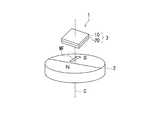
図1に示したように、本実施の形態における磁気センサシステムは、本実施の形態に係る磁気センサ1と、磁界発生部2とを備えている。磁界発生部2は、被検出磁界MFを発生する。図1に示した例では、磁界発生部2は円柱状の磁石である。この磁界発生部2は、円柱の中心軸を含む仮想の平面を中心として対称に配置されたN極とS極とを有している。この磁界発生部2は、円柱の中心軸を中心として回転する。これにより、磁界発生部2が発生する被検出磁界MFの方向は、円柱の中心軸を含む回転中心Cを中心として回転する。
As shown in FIG. 1, the magnetic sensor system in the present embodiment includes a
磁気センサ1は、基準位置における被検出磁界MFの方向が基準方向に対してなす角度を検出するものである。具体的には、磁気センサ1は、基準位置における被検出磁界MFの方向が基準方向に対してなす角度と対応関係を有する角度検出値を生成する。
The
基準位置は、磁界発生部2の一方の端面に平行な仮想の平面(以下、基準平面と言う。)内に位置する。この基準平面内において、磁界発生部2が発生する被検出磁界MFの方向は、基準位置を中心として回転する。基準方向は、基準平面内に位置して、基準位置と交差する。以下の説明において、基準位置における被検出磁界MFの方向とは、基準平面内に位置する方向を指す。また、単に被検出磁界MFの方向と言うときは、基準位置における被検出磁界MFの方向を指すものとする。磁気センサ1は、磁界発生部2の上記一方の端面に対向するように配置される。
The reference position is located in a virtual plane (hereinafter referred to as a reference plane) parallel to one end face of the
なお、磁気センサ1と磁界発生部2の構成は、図1に示した例に限られない。磁気センサ1と磁界発生部2は、被検出磁界MFの方向が磁気センサ1から見て回転するように、磁気センサ1と磁界発生部2の相対的位置関係が変化するものであればよい。例えば、図1に示したように配置された磁気センサ1と磁界発生部2において、磁界発生部2が固定されて磁気センサ1が回転してもよいし、磁気センサ1と磁界発生部2が互いに反対方向に回転してもよいし、磁気センサ1と磁界発生部2が同じ方向に互いに異なる角速度で回転してもよい。
In addition, the structure of the
また、磁界発生部2として、図1に示した磁石の代わりに、1組以上のN極とS極が交互にリング状に配列された磁石を用い、この磁石の外周の近傍に磁気センサ1が配置されていてもよい。この場合には、磁石と磁気センサ1の少なくとも一方が回転すればよい。
Further, as the magnetic
また、磁界発生部2として、図1に示した磁石の代わりに、複数組のN極とS極が交互に直線状に配列された磁気スケールを用い、この磁気スケールの外周の近傍に磁気センサ1が配置されていてもよい。この場合には、磁気スケールと磁気センサ1の少なくとも一方が、磁気スケールのN極とS極が並ぶ方向に直線的に移動すればよい。
Further, as the
上述の種々の磁気センサ1と磁界発生部2の構成においても、磁気センサ1と所定の位置関係を有する基準平面が存在し、この基準平面内において、被検出磁界MFの方向は、磁気センサ1から見て、基準位置を中心として回転する。
Also in the configuration of the various
磁気センサ1は、磁界検出部3を備えている。磁界検出部3は、被検出磁界MFを検出する複数の磁気検出素子を含み、被検出磁界MFの方向が第1の方向に対してなす角度と対応関係を有する第1の信号S1と被検出磁界MFの方向が第2の方向に対してなす角度と対応関係を有する第2の信号S2とを出力する。複数の磁気検出素子の各々は、被検出磁界MFを検出する少なくとも1つの磁気抵抗効果素子(以下、MR素子と記す。)を含んでいる。従って、磁界検出部3は、複数のMR素子を含んでいる。
The
磁界検出部3は、第1の検出回路10と第2の検出回路20を有している。図1では、理解を容易にするために、第1および第2の検出回路10,20を別体として描いているが、第1および第2の検出回路10,20は一体化されていてもよい。また、図1では、第1および第2の検出回路10,20が回転中心Cに平行な方向に積層されているが、その積層順序は図1に示した例に限られない。
The magnetic
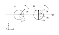
ここで、図1および図2を参照して、本実施の形態における方向と角度の定義について説明する。まず、図1に示した回転中心Cに平行で、図1における下から上に向かう方向をZ方向と定義する。図2では、Z方向を図2における奥から手前に向かう方向として表している。次に、Z方向に垂直な2方向であって、互いに直交する2つの方向をX方向とY方向と定義する。図2では、X方向を右側に向かう方向として表し、Y方向を上側に向かう方向として表している。また、X方向とは反対の方向を−X方向と定義し、Y方向とは反対の方向を−Y方向と定義する。 Here, with reference to FIG. 1 and FIG. 2, the definition of the direction and angle in this Embodiment is demonstrated. First, a direction parallel to the rotation center C shown in FIG. 1 and extending from bottom to top in FIG. 1 is defined as a Z direction. In FIG. 2, the Z direction is represented as a direction from the back to the front in FIG. Next, two directions perpendicular to the Z direction and orthogonal to each other are defined as an X direction and a Y direction. In FIG. 2, the X direction is represented as a direction toward the right side, and the Y direction is represented as a direction toward the upper side. In addition, a direction opposite to the X direction is defined as -X direction, and a direction opposite to the Y direction is defined as -Y direction.
基準位置PRは、磁気センサ1が被検出磁界MFを検出する位置である。基準方向DRは、X方向とする。被検出磁界MFの方向DMが基準方向DRに対してなす角度を記号θで表す。被検出磁界MFの方向DMは、図2において反時計回り方向に回転するものとする。角度θは、基準方向DRから反時計回り方向に見たときに正の値で表し、基準方向DRから時計回り方向に見たときに負の値で表す。
The reference position PR is a position where the
次に、図3を参照して、磁気センサ1の構成について詳しく説明する。図3は、磁気センサ1の構成を示す回路図である。磁気センサ1は、前述の磁界検出部3の他に、演算部30を備えている。前述の通り、磁界検出部3は、第1の検出回路10と第2の検出回路20を有している。
Next, the configuration of the
第1の検出回路10は、被検出磁界MFの方向DMが第1の方向に対してなす角度と対応関係を有する第1の信号S1を生成する。第2の検出回路20は、被検出磁界MFの方向DMが第2の方向に対してなす角度と対応関係を有する第2の信号S2を生成する。本実施の形態では、第1の方向はX方向であり、第2の方向はY方向である。従って、第2の方向は、第1の方向に直交している。図2において、符号D1を付した矢印は第1の方向を表し、符号D2を付した矢印は第2の方向を表している。第1の信号S1は、例えば、基準位置PRにおける被検出磁界MFの、第1の方向D1(X方向)の成分の強度に対応した信号である。第2の信号S2は、例えば、基準位置PRにおける被検出磁界MFの、第2の方向D2(Y方向)の成分の強度に対応した信号である。
The
被検出磁界MFの方向DMが所定の周期で回転する場合、第1および第2の信号S1,S2は、いずれも、上記所定の周期と等しい信号周期Tで周期的に変化する。第2の信号S2の位相は、第1の信号S1の位相と異なっている。本実施の形態では、第2の信号S2の位相は、第1の信号S1の位相に対して、信号周期Tの1/4の奇数倍だけ異なっていることが好ましい。ただし、MR素子の作製の精度等の観点から、第1の信号S1と第2の信号S2の位相差は、信号周期Tの1/4の奇数倍から、わずかにずれていてもよい。以下の説明では、第1の信号S1の位相と第2の信号S2の位相の関係が上記の好ましい関係になっているものとする。 When the direction DM of the detected magnetic field MF rotates with a predetermined period, both the first and second signals S1, S2 periodically change with a signal period T equal to the predetermined period. The phase of the second signal S2 is different from the phase of the first signal S1. In the present embodiment, the phase of the second signal S2 is preferably different from the phase of the first signal S1 by an odd multiple of 1/4 of the signal period T. However, the phase difference between the first signal S1 and the second signal S2 may be slightly deviated from an odd multiple of ¼ of the signal period T from the viewpoint of the accuracy of manufacturing the MR element. In the following description, it is assumed that the relationship between the phase of the first signal S1 and the phase of the second signal S2 is the above-described preferable relationship.
第1の検出回路10は、第1の信号S1を出力する出力端を有している。第2の検出回路20は、第2の信号S2を出力する出力端を有している。演算部30は、2つの入力端と1つの出力端とを有している。演算部30の2つの入力端は、それぞれ、第1および第2の検出回路10,20の各出力端に接続されている。
The
図4は、演算部30の構成を示す機能ブロック図である。演算部30は、角度検出値算出部31と、補正処理部32と、補正情報保持部33とを含んでいる。角度検出値算出部31は、第1および第2の検出回路10,20から出力される第1および第2の信号S1,S2に基づいて、角度θと対応関係を有する角度検出値θsを算出する。補正処理部32は、角度検出値θsに対して補正処理を行って補正後角度検出値θtを生成する。補正後角度検出値θtの誤差の絶対値の最大値は、角度検出値θsの誤差の絶対値の最大値よりも小さい。補正情報保持部33は、補正処理部32が補正処理を行う際に利用する補正情報を保持している。補正後角度検出値θtは、磁気センサ1によって検出された角度θの値である。演算部30は、例えば、特定用途向け集積回路(ASIC)またはマイクロコンピュータによって実現することができる。角度検出値算出部31における角度検出値θsの算出方法と、補正処理部32における補正処理の内容については、後で詳しく説明する。
FIG. 4 is a functional block diagram illustrating a configuration of the
また、後で詳しく説明するが、演算部30は、補正処理部32と補正情報保持部33を含まずに、磁気センサ1によって検出された角度θの値として、角度検出値θsを出力してもよい。
As will be described in detail later, the
第1の検出回路10は、ホイートストンブリッジ回路14と、差分検出器15とを有している。ホイートストンブリッジ回路14は、電源ポートV1と、グランドポートG1と、2つの出力ポートE11,E12と、直列に接続された磁気検出素子R11,R12と、直列に接続された磁気検出素子R13,R14とを含んでいる。磁気検出素子R11,R13の各一端は、電源ポートV1に接続されている。磁気検出素子R11の他端は、磁気検出素子R12の一端と出力ポートE11に接続されている。磁気検出素子R13の他端は、磁気検出素子R14の一端と出力ポートE12に接続されている。磁気検出素子R12,R14の各他端は、グランドポートG1に接続されている。電源ポートV1には、所定の大きさの電源電圧が印加される。グランドポートG1はグランドに接続される。差分検出器15は、出力ポートE11,E12の電位差に対応する信号の値を第1の信号S1として演算部30に出力する。
The
第2の検出回路20の回路構成は、第1の検出回路10と同様である。すなわち、第2の検出回路20は、ホイートストンブリッジ回路24と、差分検出器25とを有している。ホイートストンブリッジ回路24は、電源ポートV2と、グランドポートG2と、2つの出力ポートE21,E22と、直列に接続された磁気検出素子R21,R22と、直列に接続された磁気検出素子R23,R24とを含んでいる。磁気検出素子R21,R23の各一端は、電源ポートV2に接続されている。磁気検出素子R21の他端は、磁気検出素子R22の一端と出力ポートE21に接続されている。磁気検出素子R23の他端は、磁気検出素子R24の一端と出力ポートE22に接続されている。磁気検出素子R22,R24の各他端は、グランドポートG2に接続されている。電源ポートV2には、所定の大きさの電源電圧が印加される。グランドポートG2はグランドに接続される。差分検出器25は、出力ポートE21,E22の電位差に対応する信号の値を第2の信号S2として演算部30に出力する。
The circuit configuration of the
前述のように、ホイートストンブリッジ回路(以下、ブリッジ回路と記す。)14,24に含まれる複数の磁気検出素子の各々は、少なくとも1つのMR素子を含んでいる。本実施の形態では、MR素子として、スピンバルブ型MR素子、特にTMR素子を用いている。なお、TMR素子の代わりにGMR素子を用いてもよい。スピンバルブ型MR素子は、磁化方向が固定された磁化固定層と、被検出磁界MFの方向DMに応じて磁化の方向が変化する磁性層である自由層と、磁化固定層と自由層の間に配置された非磁性層とを有している。TMR素子では、非磁性層はトンネルバリア層である。GMR素子では、非磁性層は非磁性導電層である。スピンバルブ型MR素子では、自由層の磁化の方向が磁化固定層の磁化の方向に対してなす角度に応じて抵抗値が変化し、この角度が0°のときに抵抗値は最小値となり、角度が180°のときに抵抗値は最大値となる。 As described above, each of the plurality of magnetic detection elements included in the Wheatstone bridge circuits (hereinafter referred to as bridge circuits) 14 and 24 includes at least one MR element. In this embodiment, a spin valve MR element, particularly a TMR element is used as the MR element. A GMR element may be used instead of the TMR element. The spin-valve MR element includes a magnetization fixed layer whose magnetization direction is fixed, a free layer that is a magnetic layer whose magnetization direction changes according to the direction DM of the detected magnetic field MF, and between the magnetization fixed layer and the free layer. And a nonmagnetic layer. In the TMR element, the nonmagnetic layer is a tunnel barrier layer. In the GMR element, the nonmagnetic layer is a nonmagnetic conductive layer. In the spin valve MR element, the resistance value changes according to the angle formed by the magnetization direction of the free layer with respect to the magnetization direction of the magnetization fixed layer, and when this angle is 0 °, the resistance value becomes the minimum value. When the angle is 180 °, the resistance value becomes the maximum value.
本実施の形態では、特に、ブリッジ回路14,24に含まれる複数の磁気検出素子の各々は、MR素子列によって構成されている。MR素子列は、2つ以上のMR素子が直列に接続されて構成されている。MR素子列を構成する2つ以上のMR素子の数は、偶数である。MR素子列を構成する2つ以上のMR素子は、MR素子の対を1つ以上含んでいる。対を構成する2つのMR素子における磁化固定層の磁化方向は、0°および180°を除く所定の相対角度をなしている。
In the present embodiment, in particular, each of the plurality of magnetic detection elements included in the
第1の検出回路10において、第1の方向D1は、対を構成する2つのMR素子における磁化固定層の磁化方向の中間の方向またはそれとは反対の方向である。また、第2の検出回路20において、第2の方向D2は、対を構成する2つのMR素子における磁化固定層の磁化方向の中間の方向またはそれとは反対の方向である。
In the
図3には、以下のように、MR素子列を構成する複数のMR素子が、MR素子の対を1つだけ含む例を示している。磁気検出素子R11は、一対のMR素子R111,R112によって構成されている。磁気検出素子R12は、一対のMR素子R121,R122によって構成されている。磁気検出素子R13は、一対のMR素子R131,R132によって構成されている。磁気検出素子R14は、一対のMR素子R141,R142によって構成されている。磁気検出素子R21は、一対のMR素子R211,R212によって構成されている。磁気検出素子R22は、一対のMR素子R221,R222によって構成されている。磁気検出素子R23は、一対のMR素子R231,R232によって構成されている。磁気検出素子R24は、一対のMR素子R241,R242によって構成されている。図3において、塗りつぶした矢印は、MR素子における磁化固定層の磁化の方向を表し、白抜きの矢印は、MR素子における自由層の磁化の方向を表している。 FIG. 3 shows an example in which a plurality of MR elements constituting an MR element array include only one MR element pair as follows. The magnetic detection element R11 includes a pair of MR elements R111 and R112. The magnetic detection element R12 includes a pair of MR elements R121 and R122. The magnetic detection element R13 includes a pair of MR elements R131 and R132. The magnetic detection element R14 includes a pair of MR elements R141 and R142. The magnetic detection element R21 includes a pair of MR elements R211 and R212. The magnetic detection element R22 includes a pair of MR elements R221 and R222. The magnetic detection element R23 includes a pair of MR elements R231 and R232. The magnetic detection element R24 includes a pair of MR elements R241 and R242. In FIG. 3, a solid arrow indicates the magnetization direction of the magnetization fixed layer in the MR element, and a white arrow indicates the magnetization direction of the free layer in the MR element.
ここで、図5を参照して、対を構成する2つのMR素子における磁化固定層の磁化方向の関係について説明する。図5において、符号D111,D112を付した矢印は、それぞれ、MR素子R111,R112の磁化固定層の磁化方向を表している。MR素子R111,R112の磁化固定層の磁化方向D111,D112は、これらの中間の方向が第1の方向D1と同じ方向(X方向)になるように固定されている。MR素子R111の磁化固定層の磁化方向D111は、第1の方向D1から時計回り方向に角度φだけ回転した方向である。MR素子R112の磁化固定層の磁化方向D112は、第1の方向D1から反時計回り方向に角度φだけ回転した方向である。以下、角度φをオフセット角度φと言う。 Here, with reference to FIG. 5, the relationship of the magnetization direction of the magnetization fixed layer in the two MR elements constituting the pair will be described. In FIG. 5, arrows with reference signs D111 and D112 represent the magnetization directions of the magnetization fixed layers of the MR elements R111 and R112, respectively. The magnetization directions D111 and D112 of the magnetization fixed layers of the MR elements R111 and R112 are fixed so that the intermediate direction thereof is the same direction (X direction) as the first direction D1. The magnetization direction D111 of the magnetization fixed layer of the MR element R111 is a direction rotated by an angle φ clockwise from the first direction D1. The magnetization direction D112 of the magnetization fixed layer of the MR element R112 is a direction rotated by an angle φ counterclockwise from the first direction D1. Hereinafter, the angle φ is referred to as an offset angle φ.
MR素子R121,R122の磁化固定層の磁化方向は、これらの中間の方向が第1の方向D1とは反対の方向(−X方向)になるように固定されている。MR素子R131,R132の磁化固定層の磁化方向も、これらの中間の方向が第1の方向D1とは反対の方向になるように固定されている。MR素子R131の磁化固定層の磁化方向は、MR素子R121の磁化固定層の磁化方向と同じである。MR素子R132の磁化固定層の磁化方向は、MR素子R122の磁化固定層の磁化方向と同じである。MR素子R121,R131の磁化固定層の磁化方向は、図5に示したMR素子R111の磁化固定層の磁化方向D111の反対方向である。MR素子R122,R132の磁化固定層の磁化方向は、図5に示したMR素子R112の磁化固定層の磁化方向D112の反対方向である。 The magnetization directions of the magnetization fixed layers of the MR elements R121 and R122 are fixed so that the intermediate direction thereof is the opposite direction (−X direction) to the first direction D1. The magnetization directions of the magnetization fixed layers of the MR elements R131 and R132 are also fixed so that the intermediate direction thereof is opposite to the first direction D1. The magnetization direction of the magnetization fixed layer of the MR element R131 is the same as the magnetization direction of the magnetization fixed layer of the MR element R121. The magnetization direction of the magnetization fixed layer of the MR element R132 is the same as the magnetization direction of the magnetization fixed layer of the MR element R122. The magnetization direction of the magnetization fixed layer of the MR elements R121 and R131 is opposite to the magnetization direction D111 of the magnetization fixed layer of the MR element R111 shown in FIG. The magnetization direction of the magnetization fixed layer of the MR elements R122 and R132 is opposite to the magnetization direction D112 of the magnetization fixed layer of the MR element R112 shown in FIG.
MR素子R141,R142の磁化固定層の磁化方向は、これらの中間の方向が第1の方向D1と同じ方向(X方向)になるように固定されている。MR素子R141の磁化固定層の磁化方向は、図5に示したMR素子R111の磁化固定層の磁化方向D111と同じ方向である。MR素子R142の磁化固定層の磁化方向は、図5に示したMR素子R112の磁化固定層の磁化方向D112と同じ方向である。 The magnetization directions of the magnetization fixed layers of the MR elements R141 and R142 are fixed so that the intermediate direction thereof is the same direction (X direction) as the first direction D1. The magnetization direction of the magnetization fixed layer of the MR element R141 is the same as the magnetization direction D111 of the magnetization fixed layer of the MR element R111 shown in FIG. The magnetization direction of the magnetization fixed layer of the MR element R142 is the same as the magnetization direction D112 of the magnetization fixed layer of the MR element R112 shown in FIG.
図5において、符号D211,D212を付した矢印は、それぞれ、MR素子R211,R212の磁化固定層の磁化方向を表している。MR素子R211,R212の磁化固定層の磁化方向D211,D212は、これらの中間の方向が第2の方向D2と同じ方向(Y方向)になるように固定されている。MR素子R211の磁化固定層の磁化方向D211は、第2の方向D2から時計回り方向にオフセット角度φだけ回転した方向である。MR素子R212の磁化固定層の磁化方向D212は、第2の方向D2から反時計回り方向にオフセット角度φだけ回転した方向である。 In FIG. 5, arrows with symbols D211 and D212 indicate the magnetization directions of the magnetization fixed layers of the MR elements R211 and R212, respectively. The magnetization directions D211 and D212 of the magnetization fixed layers of the MR elements R211 and R212 are fixed so that the intermediate direction thereof is the same direction (Y direction) as the second direction D2. The magnetization direction D211 of the magnetization fixed layer of the MR element R211 is a direction rotated by the offset angle φ clockwise from the second direction D2. The magnetization direction D212 of the magnetization fixed layer of the MR element R212 is a direction rotated by the offset angle φ counterclockwise from the second direction D2.
MR素子R221,R222の磁化固定層の磁化方向は、これらの中間の方向が第2の方向D2とは反対の方向(−Y方向)になるように固定されている。MR素子R231,R232の磁化固定層の磁化方向も、これらの中間の方向が第2の方向D2とは反対の方向になるように固定されている。MR素子R231の磁化固定層の磁化方向は、MR素子R221の磁化固定層の磁化方向と同じである。MR素子R232の磁化固定層の磁化方向は、MR素子R222の磁化固定層の磁化方向と同じである。MR素子R221,R231の磁化固定層の磁化方向は、図5に示したMR素子R211の磁化固定層の磁化方向D211の反対方向である。MR素子R222,R232の磁化固定層の磁化方向は、図5に示したMR素子R212の磁化固定層の磁化方向D212の反対方向である。 The magnetization directions of the magnetization fixed layers of the MR elements R221 and R222 are fixed so that the intermediate direction is the opposite direction (−Y direction) to the second direction D2. The magnetization directions of the magnetization fixed layers of the MR elements R231 and R232 are also fixed so that the intermediate direction thereof is opposite to the second direction D2. The magnetization direction of the magnetization fixed layer of the MR element R231 is the same as the magnetization direction of the magnetization fixed layer of the MR element R221. The magnetization direction of the magnetization fixed layer of the MR element R232 is the same as the magnetization direction of the magnetization fixed layer of the MR element R222. The magnetization direction of the magnetization fixed layer of the MR elements R221 and R231 is opposite to the magnetization direction D211 of the magnetization fixed layer of the MR element R211 shown in FIG. The magnetization direction of the magnetization fixed layer of the MR elements R222 and R232 is opposite to the magnetization direction D212 of the magnetization fixed layer of the MR element R212 shown in FIG.
MR素子R241,R242の磁化固定層の磁化方向は、これらの中間の方向が第2の方向D2と同じ方向(Y方向)になるように固定されている。MR素子R241の磁化固定層の磁化方向は、図5に示したMR素子R211の磁化固定層の磁化方向D211と同じ方向である。MR素子R242の磁化固定層の磁化方向は、図5に示したMR素子R212の磁化固定層の磁化方向D212と同じ方向である。 The magnetization directions of the magnetization fixed layers of the MR elements R241 and R242 are fixed so that the intermediate direction thereof is the same direction (Y direction) as the second direction D2. The magnetization direction of the magnetization fixed layer of the MR element R241 is the same as the magnetization direction D211 of the magnetization fixed layer of the MR element R211 shown in FIG. The magnetization direction of the magnetization fixed layer of the MR element R242 is the same as the magnetization direction D212 of the magnetization fixed layer of the MR element R212 shown in FIG.
なお、検出回路10,20内の複数のMR素子における磁化固定層の磁化の方向は、MR素子の作製の精度等の観点から、上述の方向からわずかにずれていてもよい。
Note that the magnetization direction of the magnetization fixed layer in the plurality of MR elements in the
第1の検出回路10では、被検出磁界MFの方向DMが第1の方向D1(X方向)に対してなす角度に応じて、出力ポートE11,E12の電位差が変化する。従って、第1の検出回路10は、被検出磁界MFの方向DMが第1の方向D1(X方向)に対してなす角度と対応関係を有する第1の信号S1を生成する。
In the
第2の検出回路20では、被検出磁界MFの方向DMが第2の方向D2(Y方向)に対してなす角度に応じて、出力ポートE21,E22の電位差が変化する。従って、第2の検出回路20は、被検出磁界MFの方向DMが第2の方向D2(Y方向)に対してなす角度と対応関係を有する第2の信号S2を生成する。
In the
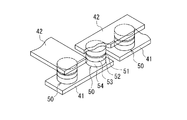
次に、図6および図7を参照して、ブリッジ回路と磁気検出素子の構成の一例について説明する。図6は、図3に示したブリッジ回路14を示す平面図である。図7は、図6における1つの磁気検出素子の一部を示す斜視図である。図6に示した例では、ブリッジ回路14の磁気検出素子R11,R12,R13,R14の各々は、直列に接続された8個のMR素子50を含むMR素子列によって構成されている。MR素子列を構成する複数のMR素子50は、MR素子50の対を4つ含んでいる。MR素子列は、8個のMR素子50を直列に接続する複数の下部電極41および複数の上部電極42を含んでいる。MR素子50は、下端面と上端面を有している。ブリッジ回路24の構成は、図6に示したブリッジ回路14と同様である。
Next, an example of the configuration of the bridge circuit and the magnetic detection element will be described with reference to FIGS. FIG. 6 is a plan view showing the
複数の下部電極41は図示しない基板上に配置されている。個々の下部電極41は細長い形状を有している。隣接する2つの下部電極41の間には、間隙が形成されている。図7に示したように、下部電極41の上面上において、長手方向の両端の近傍に、隣接する2つのMR素子50が配置されている。個々の上部電極42は細長い形状を有し、隣接する2つの下部電極41上に配置されて隣接する2つのMR素子50を電気的に接続している。
The plurality of
図7に示したように、MR素子50は、下部電極41側から順に積層された反強磁性層54、磁化固定層53、非磁性層52および自由層51を含んでいる。反強磁性層54は、反強磁性材料よりなり、磁化固定層53との間で交換結合を生じさせて、磁化固定層53の磁化の方向を固定する。なお、MR素子50における層51〜54の配置は、図7に示した配置とは上下が反対でもよい。
As shown in FIG. 7, the
自由層51は、非磁性層に接する第1の面と、その反対側の第2の面とを有している。図7に示した例では、自由層51の第2の面が、MR素子50の上端面を構成している。図2において、符号11は、第1の検出回路10内のMR素子50における自由層51の第2の面の形状を表し、符号21は、第2の検出回路20内のMR素子50における自由層51の第2の面の形状を表している。
The
図6に示したブリッジ回路14は、2つの磁気検出素子を電気的に接続する4つの接続電極431,432,433,434を有している。接続電極431〜434は、図示しない基板上に配置されている。
The
接続電極431は、磁気検出素子R11の一端に位置するMR素子50と磁気検出素子R13の一端に位置するMR素子50とを電気的に接続していると共に、電源ポートV1に電気的に接続されている。接続電極432は、磁気検出素子R11の他端に位置するMR素子50と磁気検出素子R12の一端に位置するMR素子50とを電気的に接続していると共に、出力ポートE11に電気的に接続されている。接続電極433は、磁気検出素子R13の他端に位置するMR素子50と磁気検出素子R14の一端に位置するMR素子50とを電気的に接続していると共に、出力ポートE12に電気的に接続されている。接続電極434は、磁気検出素子R12の他端に位置するMR素子50と磁気検出素子R14の他端に位置するMR素子50とを電気的に接続していると共に、グランドポートG1に電気的に接続されている。
The
磁気検出素子R11では、例えば、電源ポートV1側から1番目ないし4番目のMR素子50の磁化固定層の磁化方向は、図3に示したMR素子R111の磁化固定層の磁化方向と同じであり、電源ポートV1側から5番目ないし8番目のMR素子50の磁化固定層の磁化方向は、図3に示したMR素子R112の磁化固定層の磁化方向と同じである。この場合、1番目と5番目のMR素子50、2番目と6番目のMR素子50、3番目と7番目のMR素子50、4番目と8番目のMR素子50が、それぞれ対を構成している。
In the magnetic detection element R11, for example, the magnetization direction of the magnetization fixed layer of the first to
磁気検出素子R12では、例えば、出力ポートE11側から1番目ないし4番目のMR素子50の磁化固定層の磁化方向は、図3に示したMR素子R121の磁化固定層の磁化方向と同じであり、出力ポートE11側から5番目ないし8番目のMR素子50の磁化固定層の磁化方向は、図3に示したMR素子R122の磁化固定層の磁化方向と同じである。この場合、1番目と5番目のMR素子50、2番目と6番目のMR素子50、3番目と7番目のMR素子50、4番目と8番目のMR素子50が、それぞれ対を構成している。
In the magnetic detection element R12, for example, the magnetization direction of the magnetization fixed layer of the first to
磁気検出素子R13では、例えば、電源ポートV1側から1番目ないし4番目のMR素子50の磁化固定層の磁化方向は、図3に示したMR素子R131の磁化固定層の磁化方向と同じであり、電源ポートV1側から5番目ないし8番目のMR素子50の磁化固定層の磁化方向は、図3に示したMR素子R132の磁化固定層の磁化方向と同じである。この場合、1番目と5番目のMR素子50、2番目と6番目のMR素子50、3番目と7番目のMR素子50、4番目と8番目のMR素子50が、それぞれ対を構成している。
In the magnetic detection element R13, for example, the magnetization direction of the magnetization fixed layer of the first to
磁気検出素子R14では、例えば、出力ポートE12側から1番目ないし4番目のMR素子50の磁化固定層の磁化方向は、図3に示したMR素子R141の磁化固定層の磁化方向と同じであり、出力ポートE12側から5番目ないし8番目のMR素子50の磁化固定層の磁化方向は、図3に示したMR素子R142の磁化固定層の磁化方向と同じである。この場合、1番目と5番目のMR素子50、2番目と6番目のMR素子50、3番目と7番目のMR素子50、4番目と8番目のMR素子50が、それぞれ対を構成している。
In the magnetic detection element R14, for example, the magnetization direction of the magnetization fixed layer of the first to
次に、図3および図4を参照して、角度検出値算出部31における角度検出値θsの算出方法について説明する。図3に示した例では、理想的には、第1の信号S1の波形は、角度θに依存したコサイン(Cosine)波形になり、第2の信号S2の波形は、角度θに依存したサイン(Sine)波形になる。この場合、第2の信号S2の位相は、第1の信号S1の位相に対して、信号周期Tの1/4すなわちπ/2(90°)だけ異なっている。
Next, a method for calculating the angle detection value θs in the angle detection
角度θが0°以上90°未満のとき、および270°より大きく360°以下のときは、第1の信号S1は正の値であり、角度θが90°よりも大きく270°よりも小さいときは、第1の信号S1は負の値である。また、角度θが0°よりも大きく180°よりも小さいときは、第2の信号S2は正の値であり、角度θが180°よりも大きく360°よりも小さいときは、第2の信号S2は負の値である。 When the angle θ is greater than or equal to 0 ° and less than 90 °, and greater than 270 ° and less than or equal to 360 °, the first signal S1 is a positive value, and the angle θ is greater than 90 ° and smaller than 270 ° The first signal S1 has a negative value. When the angle θ is larger than 0 ° and smaller than 180 °, the second signal S2 is a positive value. When the angle θ is larger than 180 ° and smaller than 360 °, the second signal S2 is positive. S2 is a negative value.
角度検出値算出部31は、第1および第2の信号S1,S2に基づいて、角度θと対応関係を有する角度検出値θsを算出する。具体的には、例えば、角度検出値算出部31は、下記の式(1)によって、θsを算出する。なお、“atan”は、アークタンジェントを表す。
The detected angle
θs=atan(S2/S1) …(1) θs = atan (S2 / S1) (1)
式(1)におけるatan(S2/S1)は、θsを求めるアークタンジェント計算を表している。なお、θsが0°以上360°未満の範囲内では、式(1)におけるθsの解には、180°異なる2つの値がある。しかし、S1,S2の正負の組み合わせにより、θsの真の値が、式(1)におけるθsの2つの解のいずれであるかを判別することができる。すなわち、S1が正の値のときは、θsは、0°以上90゜未満、および270°より大きく360°以下の範囲内である。S1が負の値のときは、θsは90°よりも大きく270°よりも小さい。S2が正の値のときは、θsは0°よりも大きく180°よりも小さい。S2が負の値のときは、θsは180°よりも大きく360°よりも小さい。角度検出値算出部31は、式(1)と、上記のS1,S2の正負の組み合わせの判定により、0°以上360°未満の範囲内でθsを求める。
Atan (S2 / S1) in Equation (1) represents arctangent calculation for obtaining θs. In the range where θs is 0 ° or more and less than 360 °, the solution of θs in Equation (1) has two values that differ by 180 °. However, it is possible to determine which of the two solutions of θs in Equation (1) is the true value of θs by the positive / negative combination of S1 and S2. That is, when S1 is a positive value, θs is in the range of 0 ° to less than 90 ° and greater than 270 ° to 360 °. When S1 is a negative value, θs is greater than 90 ° and smaller than 270 °. When S2 is a positive value, θs is larger than 0 ° and smaller than 180 °. When S2 is a negative value, θs is greater than 180 ° and smaller than 360 °. The detected
前述の通り、被検出磁界MFの方向DMが前記所定の周期で回転する場合、第1および第2の信号S1,S2は、いずれも、前記所定の周期と等しい信号周期Tで周期的に変化する。信号S1,S2の各々の波形は、理想的には正弦曲線(サイン(Sine)波形とコサイン(Cosine)波形を含む)となる。しかし、実際には、例えば、MR素子50の磁化固定層53の磁化方向が被検出磁界MF等の影響によって変動したり、MR素子50の自由層51の磁化方向が、自由層51の形状異方性等の影響によって、被検出磁界MFの方向DMと一致しなかったりすることに起因して、信号S1,S2の各々の波形は、正弦曲線から歪む。
As described above, when the direction DM of the detected magnetic field MF rotates with the predetermined period, the first and second signals S1 and S2 change periodically with a signal period T equal to the predetermined period. To do. Each of the signals S1 and S2 is ideally a sine curve (including a sine waveform and a cosine waveform). However, actually, for example, the magnetization direction of the magnetization fixed
信号S1,S2の各々の波形が正弦曲線から歪むということは、信号S1,S2の各々は、理想的な正弦曲線を描くように周期的に変化する理想成分と、この理想成分に対する1つ以上の高調波に相当する1つ以上の誤差成分とを含むということである。信号S1,S2の各々が1つ以上の誤差成分を含むことによって、角度検出値θsは、誤差を含むことになる。以下、角度検出値θsの誤差を角度誤差と言う。被検出磁界MFの方向DMが前記所定の周期で回転する場合、角度誤差は、前記所定の周期とは異なる1つ以上の周期で周期的に変化する1つ以上の角度誤差成分を含み得る。 The fact that each of the waveforms of the signals S1 and S2 is distorted from the sine curve means that each of the signals S1 and S2 has an ideal component that periodically changes to draw an ideal sine curve and one or more of the ideal components. And one or more error components corresponding to the higher harmonics. Since each of the signals S1 and S2 includes one or more error components, the detected angle value θs includes an error. Hereinafter, an error in the detected angle value θs is referred to as an angle error. When the direction DM of the detected magnetic field MF rotates at the predetermined period, the angle error may include one or more angular error components that periodically change at one or more periods different from the predetermined period.
本願の発明者による研究の課程で、一般的に、磁気センサでは、角度誤差が被検出磁界の強度に応じて変化すること、すなわち角度誤差の磁界強度依存が存在することが分かった。また、本願の発明者による研究の課程で、角度誤差の磁界強度依存は、主に、前述の1つ以上の角度誤差成分のうちの、前記所定の周期の1/4の周期で変化する角度誤差成分(以下、角度誤差4次成分と言う。)に起因するものであることが分かった。すなわち、磁界検出部3における被検出磁界MFの強度(以下、印加磁界強度と言う。)の変化に対する角度誤差4次成分の変化の仕方は、印加磁界強度の変化に対する角度誤差全体の変化の仕方と同様であった。また、角度誤差4次成分を低減することによって、角度誤差全体を低減することができることも分かった。
In the course of research by the inventors of the present application, it has been found that, in general, in a magnetic sensor, the angle error changes according to the strength of the detected magnetic field, that is, the angle error depends on the magnetic field strength. In addition, in the course of research by the inventors of the present application, the dependence of the angle error on the magnetic field strength is mainly an angle that changes at a quarter of the predetermined period among the one or more angle error components described above. It was found that it was caused by an error component (hereinafter referred to as an angular error quaternary component). That is, the manner in which the angular error quaternary component changes with respect to the change in the intensity of the detected magnetic field MF (hereinafter referred to as applied magnetic field strength) in the magnetic
ここで、上記角度誤差の磁界強度依存に起因して、磁気センサ1の使用時の印加磁界強度の範囲として想定される所定の範囲内において角度誤差の変動量が大きくなる場合について考える。この場合、印加磁界強度が上記所定の範囲内の特定の値のときに角度誤差が低減されるように検出角度の補正処理を行っても、印加磁界強度が上記特定の値と異なるときには、角度誤差が十分に低減されないことが起こり得る。
Here, consider a case where the variation amount of the angle error becomes large within a predetermined range assumed as the range of the applied magnetic field strength when the
被検出磁界MFの方向DMが前記所定の周期で回転する場合における角度誤差4次成分の絶対値の最大値を、記号E4で表す。印加磁界強度の広い範囲で角度誤差4次成分の絶対値の最大値E4の変動量を小さくすれば、印加磁界強度の広い範囲で角度誤差の変動量を小さくすることができる。そのようにできれば、たとえ角度誤差は大きくても、印加磁界強度によって異なることのない補正処理を行うことによって、印加磁界強度の広い範囲で角度誤差を低減することが可能になる。 The maximum value of the absolute value of the angular error quaternary component when the direction DM of the detected magnetic field MF rotates in the predetermined cycle is represented by the symbol E4. If the variation amount of the maximum value E4 of the absolute value of the angular error quaternary component is reduced in a wide range of the applied magnetic field strength, the variation amount of the angle error can be reduced in a wide range of the applied magnetic field strength. By doing so, even if the angle error is large, it is possible to reduce the angle error in a wide range of the applied magnetic field strength by performing a correction process that does not vary depending on the applied magnetic field strength.
本実施の形態に係る磁気センサ1では、印加磁界強度が、20〜150mTの範囲の一部である副範囲であって、上限と下限の差が30mT以上である副範囲内で変化するときの角度誤差4次成分の絶対値の最大値E4の変動量は0.1°以下である。上限と下限の差が30mT以上という副範囲の広さは、磁気センサ1の実用上、磁気センサ1の使用時の印加磁界強度の範囲の広さとして十分に広いと言える。このような特性を有する本実施の形態に係る磁気センサ1によれば、印加磁界強度の広い範囲で角度誤差の変動量を小さくすることが可能になる。
In the
以下、磁気センサ1の上記特性を実現するための方法について詳しく説明する。本願の発明者による研究により、角度誤差4次成分は、信号S1,S2の各々に含まれる2つの誤差成分に依存することが分かった。始めに、これについて説明する。被検出磁界MFの方向DMが前記所定の周期で回転する場合、第1の信号S1は、理想的な正弦曲線を描くように周期的に変化する第1の理想成分V11と、第1の理想成分V11に対する第3高調波に相当する誤差成分である第1の第3高調波成分V13と、第1の理想成分V11に対する第5高調波に相当する誤差成分である第1の第5高調波成分V15とを含み、第2の信号S2は、理想的な正弦曲線を描くように周期的に変化する第2の理想成分V21と、第2の理想成分V21に対する第3高調波に相当する誤差成分である第2の第3高調波成分V23と、第2の理想成分V21に対する第5高調波に相当する誤差成分である第2の第5高調波成分V25とを含んでいる。
Hereinafter, a method for realizing the above characteristics of the
ここで、第1の理想成分V11が最大値をとるときの第1の理想成分V11に対する第1の第3高調波成分V13の比率を第1の比率V13rと定義し、第1の理想成分V11が最大値をとるときの第1の理想成分V11に対する第1の第5高調波成分V15の比率を第2の比率V15rと定義し、第2の理想成分V21が最大値をとるときの第2の理想成分V21に対する第2の第3高調波成分V23の比率を第3の比率V23rと定義し、第2の理想成分V21が最大値をとるときの第2の理想成分V21に対する第2の第5高調波成分V25の比率を第4の比率V25rと定義する。また、第1の比率V13rと第3の比率V23rの平均値を、第3高調波成分比率と定義し、記号V3rで表す。また、第2の比率V15rと第4の比率V25rの平均値を、第5高調波成分比率と定義し、記号V5rで表す。 Here, the ratio of the first third harmonic component V13 to the first ideal component V11 when the first ideal component V11 takes the maximum value is defined as a first ratio V13r, and the first ideal component V11 The ratio of the first fifth harmonic component V15 with respect to the first ideal component V11 when A takes the maximum value is defined as a second ratio V15r, and the second when the second ideal component V21 takes the maximum value The ratio of the second third harmonic component V23 to the ideal component V21 is defined as the third ratio V23r, and the second second component V21 relative to the second ideal component V21 when the second ideal component V21 takes the maximum value is defined. The ratio of the fifth harmonic component V25 is defined as a fourth ratio V25r. The average value of the first ratio V13r and the third ratio V23r is defined as the third harmonic component ratio and is represented by the symbol V3r. The average value of the second ratio V15r and the fourth ratio V25r is defined as the fifth harmonic component ratio and is represented by the symbol V5r.
本願の発明者による研究により、角度誤差4次成分の絶対値の最大値E4は、第3高調波成分比率V3rと第5高調波成分比率V5rの差の絶対値に比例することが分かった。E4は、近似的に次の式(2)で表される。なお、式(2)において、E4の単位は度であり、V3r,V5rの単位は%である。 According to the research by the inventors of the present application, it has been found that the maximum absolute value E4 of the angular error quaternary component is proportional to the absolute value of the difference between the third harmonic component ratio V3r and the fifth harmonic component ratio V5r. E4 is approximately represented by the following equation (2). In the formula (2), the unit of E4 is degree, and the unit of V3r and V5r is%.
E4=|V3r−V5r|×0.56 …(2) E4 = | V3r−V5r | × 0.56 (2)
式(2)から、原理的に、V3rとV5rが等しいときにE4はゼロになる。また、式(2)から、V3rとV5rの差の絶対値が0.18%のときにE4は0.1°になり、V3rとV5rの差の絶対値が0.09%のときにE4は0.05°になる。 From equation (2), in principle, E4 becomes zero when V3r and V5r are equal. Further, from the formula (2), E4 becomes 0.1 ° when the absolute value of the difference between V3r and V5r is 0.18%, and E4 when the absolute value of the difference between V3r and V5r is 0.09%. Becomes 0.05 °.
以下、印加磁界強度が副範囲内で変化するときのV3rとV5rの差の絶対値の変動量を、副範囲内におけるV3rとV5rの差の絶対値の変動量とも言う。また、印加磁界強度が副範囲内で変化するときのE4の変動量を、副範囲内におけるE4の変動量とも言う。式(2)から、副範囲内におけるV3rとV5rの差の絶対値の変動量が0.18%以下であれば、副範囲内におけるE4の変動量は0.1°以下になる。また、副範囲内におけるV3rとV5rの差の絶対値の変動量が0.09%以下であれば、副範囲内におけるE4の変動量は0.05°以下になる。 Hereinafter, the amount of change in the absolute value of the difference between V3r and V5r when the applied magnetic field strength changes within the subrange is also referred to as the amount of change in the absolute value of the difference between V3r and V5r within the subrange. Further, the variation amount of E4 when the applied magnetic field intensity changes within the sub-range is also referred to as the variation amount of E4 within the sub-range. From equation (2), if the fluctuation amount of the absolute value of the difference between V3r and V5r within the subrange is 0.18% or less, the fluctuation amount of E4 within the subrange is 0.1 ° or less. Further, if the variation amount of the absolute value of the difference between V3r and V5r within the sub-range is 0.09% or less, the variation amount of E4 within the sub-range is 0.05 ° or less.
ここで、図8ないし図11を参照して、シミュレーションによって求めた複数の誤差成分と角度誤差4次成分との関係の第1ないし第4の例について説明する。 Here, with reference to FIGS. 8 to 11, first to fourth examples of the relationship between a plurality of error components obtained by simulation and an angular error quaternary component will be described.
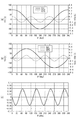
図8ないし図11において、(a)はV11,V13r,V15rの各波形を示し、(b)はV21,V23r,V25rの各波形を示し、(c)は角度誤差4次成分の波形を示している。(a)、(b)、(c)のいずれにおいても、横軸は角度θを示している。(a)における縦軸はV11,V13r,V15rの各値を示している。V11は、その最大値を100%として表している。(b)における縦軸はV21,V23r,V25rの各値を示している。V21は、その最大値を100%として表している。(c)における縦軸は、角度誤差4次成分の値(単位は度)を示している。 8 to 11, (a) shows the waveforms of V11, V13r, and V15r, (b) shows the waveforms of V21, V23r, and V25r, and (c) shows the waveform of the angular error quaternary component. ing. In any of (a), (b), and (c), the horizontal axis indicates the angle θ. The vertical axis | shaft in (a) has shown each value of V11, V13r, V15r. V11 represents the maximum value as 100%. The vertical axis | shaft in (b) has shown each value of V21, V23r, V25r. V21 represents the maximum value as 100%. The vertical axis in (c) indicates the value of the angular error quaternary component (the unit is degrees).
図8に示した第1の例では、V13r,V15r,V23r,V25rがいずれも0.1%である。この場合、V3r,V5rはいずれも0.1%である。この場合は、V3rとV5rが等しいことから、角度誤差4次成分は、角度θに関わらずにゼロであり、E4はゼロである。 In the first example shown in FIG. 8, V13r, V15r, V23r, and V25r are all 0.1%. In this case, both V3r and V5r are 0.1%. In this case, since V3r and V5r are equal, the angular error quaternary component is zero regardless of the angle θ, and E4 is zero.
図9に示した第2の例では、V13r,V23rがいずれもゼロであり、V15r,V25rがいずれも0.1%である。この場合、V3rはゼロであり、V5rは0.1%である。この場合は、V3rとV5rの差の絶対値は0.1%であり、E4は0.056°である。 In the second example shown in FIG. 9, both V13r and V23r are zero, and both V15r and V25r are 0.1%. In this case, V3r is zero and V5r is 0.1%. In this case, the absolute value of the difference between V3r and V5r is 0.1%, and E4 is 0.056 °.
図10に示した第3の例では、V13r,V23rがいずれも0.1%であり、V15r,V25rがいずれもゼロである。この場合、V3rは0.1%であり、V5rはゼロである。この場合は、V3rとV5rの差の絶対値は0.1%であり、E4は0.056°である。 In the third example shown in FIG. 10, V13r and V23r are both 0.1%, and V15r and V25r are both zero. In this case, V3r is 0.1% and V5r is zero. In this case, the absolute value of the difference between V3r and V5r is 0.1%, and E4 is 0.056 °.
図11に示した第4の例では、V13r,V23rがいずれも−0.1%であり、V15r,V25rがいずれも0.1%である。この場合、V3rは−0.1%であり、V5rは0.1%である。この場合は、V3rとV5rの差の絶対値は0.2%であり、E4は0.11°である。 In the fourth example shown in FIG. 11, V13r and V23r are both -0.1%, and V15r and V25r are both 0.1%. In this case, V3r is -0.1% and V5r is 0.1%. In this case, the absolute value of the difference between V3r and V5r is 0.2%, and E4 is 0.11 °.
次に、図12を参照して、式(2)で表されるV3rとV5rの差の絶対値とE4との関係を求めたシミュレーションの結果について説明する。このシミュレーションでは、V3rとV5rの値の種々の組み合わせについて、V3rとV5rの差の絶対値とE4との関係を求めた。その結果を図12に示す。図12において、横軸はV3rとV5rの差の絶対値を示し、縦軸はE4を示している。また、図12において、複数の四角の点は、それぞれシミュレーションで求めたV3rとV5rの差の絶対値とE4の値の組み合わせを示し、直線は、V3rとV5rの差の絶対値とE4の関係を表す近似直線である。式(2)は、この近似直線を表している。 Next, with reference to FIG. 12, the result of the simulation which calculated | required the relationship between the absolute value of the difference of V3r and V5r represented by Formula (2), and E4 is demonstrated. In this simulation, the relationship between the absolute value of the difference between V3r and V5r and E4 was determined for various combinations of the values of V3r and V5r. The result is shown in FIG. In FIG. 12, the horizontal axis indicates the absolute value of the difference between V3r and V5r, and the vertical axis indicates E4. In FIG. 12, a plurality of square points represent combinations of the absolute value of the difference between V3r and V5r and the value of E4 obtained by simulation, respectively, and the straight line represents the relationship between the absolute value of the difference between V3r and V5r and E4. Is an approximate straight line. Equation (2) represents this approximate straight line.
以下、印加磁界強度を変化させたときのV3r,V5r,E4の変化の仕方を、それぞれ、V3r,V5r,E4の磁界強度依存性と言う。前述の通り、E4は、V3rとV5rの差の絶対値に比例する。このことから、所望の副範囲内におけるE4の変動量を小さくするには、その副範囲内において、各印加磁界強度におけるV3rとV5rの差の絶対値の変動量を小さくすればよいことが分かる。これは、その副範囲内において印加磁界強度の増加に対するV3rの変化の割合と印加磁界強度の増加に対するV5rの変化の割合が互いに近づくように、V3rとV5rの磁界強度依存性を制御することによって実現することができる。 Hereinafter, changes in V3r, V5r, and E4 when the applied magnetic field strength is changed are referred to as magnetic field strength dependence of V3r, V5r, and E4, respectively. As described above, E4 is proportional to the absolute value of the difference between V3r and V5r. From this, it can be seen that in order to reduce the fluctuation amount of E4 within the desired sub-range, it is only necessary to reduce the fluctuation amount of the absolute value of the difference between V3r and V5r in each applied magnetic field strength within that sub-range. . This is because by controlling the magnetic field strength dependence of V3r and V5r so that the rate of change in V3r with respect to the increase in applied magnetic field strength and the rate of change in V5r with respect to the increase in applied magnetic field strength are close to each other within the sub-range. Can be realized.
本実施の形態では、以下で説明する第1の手段と第2の手段を用いて、所望の副範囲において印加磁界強度の増加に対するV3rの変化の割合と印加磁界強度の増加に対するV5rの変化の割合が互いに近づくように、V3rの磁界強度依存性とV5rの磁界強度依存性を制御する。第1の手段は、MR素子50の形状、特に自由層51の形状を制御することである。第2の手段は、図5を参照して説明したオフセット角度φを調整することである。
In the present embodiment, by using the first means and the second means described below, the ratio of the change in V3r with respect to the increase in the applied magnetic field strength and the change in V5r with respect to the increase in the applied magnetic field strength in the desired subrange. The magnetic field strength dependency of V3r and the magnetic field strength dependency of V5r are controlled so that the ratios are close to each other. The first means is to control the shape of the
始めに、第1の手段について説明する。まず、図13ないし図15を参照して、本実施の形態における自由層51の形状の制御の方法について説明する。本実施の形態では、自由層51の形状を、自由層51の第2の面の形状によって規定する。MR素子50は、例えば、MR素子50を構成する複数の層となる複数の膜の積層体を形成した後、所望の形状のエッチングマスクを用いて、積層体をエッチングすることによって作製される。自由層51の第2の面の形状は、エッチングマスクの形状によって規定される。自由層51の第1の面、ならびにMR素子50を構成する自由層51以外の複数の層のそれぞれの上面および下面の形状は、自由層51の第2の面の形状と同一であるか相似形である。
First, the first means will be described. First, a method for controlling the shape of the
図13は、自由層51の第2の面の形状を説明するための説明図である。図13において、符号51aは、自由層51の第2の面の外縁を示している。なお、図13では、理解を容易にするために、第2の面の外縁51aの形状を、誇張して描いている。また、符号51Cは、自由層51の第2の面の形状を定義するために使用する基準円を示している。基準円51Cは、真円である。
FIG. 13 is an explanatory diagram for explaining the shape of the second surface of the
ここで、自由層51の第2の面の面重心を、第2の面の中心と定義する。また、第2の面の外縁51a上の任意の点と第2の面の中心とを結ぶ直線が、X方向(図2参照)に対してなす角度を記号θaで表す。角度θaは、X方向から反時計回り方向に見たときの値で表す。角度θaの範囲は、0°以上360°未満である。また、第2の面の中心から、第2の面の外縁51a上の任意の点までの距離をR(θa)と定義する。
Here, the center of gravity of the second surface of the
本実施の形態では、MR素子50の作製段階で、第2の面の形状を以下のように制御する。すなわち、本実施の形態では、第2の面の形状を、5回以上の回転対称とはならない4回対称の回転対称形状にすると共に、後で説明する歪み比率と歪み方向を制御する。5回以上の回転対称とはならない4回対称の回転対称形状は、nを2以上の整数としたときに、4×n回の回転対称となる形状を含まない。以下、5回以上の回転対称とはならない4回対称の回転対称形状を、4回対称形状と言う。
In the present embodiment, the shape of the second surface is controlled as follows at the stage of manufacturing the
第2の面の形状が4回対称形状である場合には、角度θaを0°以上360°未満の範囲内で変化させると、R(θa)は、角度θaが90°ずつ異なる4つの値のときに最大値をとり、角度θaが90°ずつ異なる他の4つの値のときに最小値をとるように変化する。 When the shape of the second surface is a 4-fold symmetrical shape, when the angle θa is changed within the range of 0 ° or more and less than 360 °, R (θa) has four values different from each other by 90 °. In this case, the maximum value is taken, and the angle θa is changed to take the minimum value when the other four values differ by 90 °.
ここで、R(θa)の最大値とR(θa)の最小値の平均値を基準円51Cの半径Rcとして、基準円51Cを定義する。基準円51Cの中心は、第2の面の中心と一致している。また、R(θa)の最大値から基準円51Cの半径Rcを引いた値を歪み長dと定義する。また、Rcに対する歪み長dの比率を百分率で表したものを歪み比率drと定義し、Rcに対するR(θa)の比率を百分率で表したものをr(θa)と定義する。また、角度θaが0°以上90°未満の範囲内でR(θa)が最大値をとるときの角度θaを、歪み方向αと定義する。本実施の形態では、r(θa)は、例えば次の式(3)で表される。
Here, the
r(θa)=100+dr・cos(4(θa−α)) …(3) r (θa) = 100 + dr · cos (4 (θa−α)) (3)
図14は、角度θaとr(θa)の関係の一例を示している。この例では、歪み比率drは1%であり、歪み方向αは0°である。 FIG. 14 shows an example of the relationship between the angles θa and r (θa). In this example, the strain ratio dr is 1%, and the strain direction α is 0 °.
図15は、角度θaとr(θa)が図14に示した関係を有する場合について、角度θaが0°から90°の範囲における基準円51Cと第2の面の外縁51aのそれぞれの一部を示している。図15において、横軸はX方向の位置を示し、縦軸はY方向の位置を示している。このX方向の位置とY方向の位置は、基準円51Cの中心を原点として、基準円51Cの半径Rcを100としたときの相対値で表されている。
FIG. 15 shows a case where the angle θa and r (θa) have the relationship shown in FIG. 14 and a part of the
本実施の形態において、歪み比率drの調整範囲は、0〜10%であることが好ましい。もし第2の面の外縁51aの形状を正方形にすると、歪み比率drは10%を超える。本実施の形態では、第2の面の外縁51aの形状は、正方形を含まない。なお、歪み比率drを1%程度としたときの第2の面の外縁51aの形状は、図13に示したように真円から大きく歪んだものではなく、図15に示したように真円に近いものとなる。
In the present embodiment, the adjustment range of the strain ratio dr is preferably 0 to 10%. If the shape of the
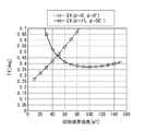
次に、第1の実験の結果を参照して、自由層51の第2の面の形状を変えることによって、V3r,V5r,E4のそれぞれの磁界強度依存性を変えることができることについて説明する。第1の実験では、オフセット角度φを0°にし、自由層51の第2の面の形状を、第1ないし第3の形状の3通りに変えて、V3r,V5r,E4のそれぞれの磁界強度依存性を調べた。図16は、自由層51の第2の面の形状を変えたときのV3r,V5rのそれぞれの磁界強度依存性の変化を示す特性図である。図17は、自由層51の第2の面の形状を変えたときのE4の磁界強度依存性の変化を示す特性図である。
Next, with reference to the result of the first experiment, it will be described that the magnetic field dependency of each of V3r, V5r, and E4 can be changed by changing the shape of the second surface of the
自由層51の第2の面の形状は、歪み比率drと歪み方向αで規定される。第2の面の第1の形状は、drが0.5%であり、αが45°である形状である。第2の面の第2の形状は、drがゼロである形状である。第2の面の第3の形状は、drが0.5%であり、αが0°である形状である。図16では、第1の形状に対応するV3r,V5rをV3r(dr=0.5%,α=45°),V5r(dr=0.5%,α=45°)と表記し、第2の形状に対応するV3r,V5rをV3r(dr=0),V5r(dr=0)と表記し、第3の形状に対応するV3r,V5rをV3r(dr=0.5%,α=0°),V5r(dr=0.5%,α=0°)と表記している。また、図17では、第1の形状に対応するE4をE4(dr=0.5%,α=45°)と表記し、第2の形状に対応するE4をE4(dr=0)と表記し、第3の形状に対応するE4をE4(dr=0.5%,α=0°)と表記している。
The shape of the second surface of the
なお、図16および図17は、歪み比率drと歪み方向αの少なくとも一方を変えたときのV3r,V5r,E4の磁界強度依存性の変化の仕方の傾向を説明するために示した一例である。図16および図17には示していないが、αを一定にしてdxを変化させると、dxが大きくなるほど、以下で説明する傾向のV3r,V5r,E4の磁界強度依存性の変化が顕著に現れ、dxが小さくなるほど、V3r,V5r,E4の磁界強度依存性は、それぞれdrがゼロである場合におけるV3r,V5r,E4の磁界強度依存性に近づく。 16 and 17 are examples shown for explaining the tendency of the change in the magnetic field strength dependency of V3r, V5r, and E4 when at least one of the strain ratio dr and the strain direction α is changed. . Although not shown in FIGS. 16 and 17, when dx is changed while α is constant, changes in the magnetic field strength dependence of V3r, V5r, and E4 tend to be described more significantly as dx increases. , Dx decreases, the magnetic field strength dependence of V3r, V5r, E4 approaches the magnetic field strength dependence of V3r, V5r, E4 when dr is zero, respectively.
図16から、V3r,V5rの磁界強度依存性の変化の仕方の傾向として、以下のようなことが分かる。まず、歪み比率drをゼロより大きい値にすると、歪み比率drがゼロである場合に比べて、V3rの磁界強度依存性とV5rの磁界強度依存性が変化する。また、V3rの磁界強度依存性とV5rの磁界強度依存性は、歪み方向αによっても変化する。また、歪み比率drと歪み方向αの少なくとも一方を変えたときのV3rの磁界強度依存性の変化の仕方とV5rの磁界強度依存性の変化の仕方は、互いに異なる。図16に示した例では、drがゼロである場合に比べて、drを0.5%、αを0°にすると、V3rの磁界強度依存性は、V3rが増加するように変化するのに対し、V5rの磁界強度依存性は、V5rが減少するように変化する。また、drがゼロである場合に比べて、drを0.5%、αを45°にすると、V3rの磁界強度依存性は、V3rが減少するように変化するのに対し、V5rの磁界強度依存性は、V5rが増加するように変化する。 From FIG. 16, the following can be seen as the tendency of the change in the magnetic field strength dependence of V3r and V5r. First, when the strain ratio dr is set to a value larger than zero, the magnetic field strength dependency of V3r and the magnetic field strength dependency of V5r are changed as compared with the case where the strain ratio dr is zero. Further, the magnetic field strength dependency of V3r and the magnetic field strength dependency of V5r also change depending on the strain direction α. Further, the method of changing the magnetic field strength dependency of V3r and the method of changing the magnetic field strength dependency of V5r when at least one of the strain ratio dr and the strain direction α is changed are different from each other. In the example shown in FIG. 16, when dr is 0.5% and α is 0 °, the magnetic field strength dependence of V3r changes so that V3r increases as compared with the case where dr is zero. On the other hand, the magnetic field strength dependence of V5r changes so that V5r decreases. In addition, when dr is 0.5% and α is 45 ° as compared to when dr is zero, the dependence of V3r on the magnetic field strength changes so that V3r decreases, whereas the magnetic field strength of V5r. The dependence changes as V5r increases.
また、歪み比率drと歪み方向αの少なくとも一方を変えたときのV3rの変化量と、歪み比率drと歪み方向αの少なくとも一方を変えたときのV5rの変化量は、いずれも、印加磁界強度によって異なっている。 The change amount of V3r when at least one of the strain ratio dr and the strain direction α is changed, and the change amount of V5r when at least one of the strain ratio dr and the strain direction α is changed are both applied magnetic field strength. It depends on.
上述のように、歪み比率drと歪み方向αの少なくとも一方を変えたときのV3rの磁界強度依存性の変化の仕方とV5rの磁界強度依存性の変化の仕方が互いに異なることにより、図17に示したように、歪み比率drと歪み方向αの少なくとも一方を変えることによって、E4の磁界強度依存性を変えることができる。 As described above, the change in the magnetic field strength dependency of V3r and the change in the magnetic field strength dependency of V5r when changing at least one of the strain ratio dr and the strain direction α are different from each other in FIG. As shown, the dependence of E4 on the magnetic field strength can be changed by changing at least one of the strain ratio dr and the strain direction α.
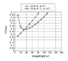
次に、第2の実験の結果を参照して、第2の手段について説明する。第2の実験では、自由層51の第2の面の形状を、drがゼロである形状にし、オフセット角度φを0°、8°、17°の3通りに変えて、V3r,V5r,E4のそれぞれの磁界強度依存性を調べた。図18は、オフセット角度φを変えたときのV3r,V5rのそれぞれの磁界強度依存性の変化を示す特性図である。図19は、オフセット角度φを変えたときのE4の磁界強度依存性の変化を示す特性図である。
Next, the second means will be described with reference to the result of the second experiment. In the second experiment, the shape of the second surface of the
図18では、オフセット角度φを0°としたときのV3r,V5rをV3r(φ=0°),V5r(φ=0°)と表記し、オフセット角度φを8°としたときのV3r,V5rをV3r(φ=8°),V5r(φ=8°)と表記し、オフセット角度φを17°としたときのV3r,V5rをV3r(φ=17°),V5r(φ=17°)と表記している。なお、図18では、V5r(φ=0°)、V5r(φ=8°)、V5r(φ=17°)に対応する3つの線は、重なっている。また、図19では、オフセット角度φを0°としたときのE4をE4(φ=0°)と表記し、オフセット角度φを8°としたときのE4をE4(φ=8°)と表記し、オフセット角度φを17°としたときのE4をE4(φ=17°)と表記している。 In FIG. 18, V3r and V5r when the offset angle φ is 0 ° are expressed as V3r (φ = 0 °) and V5r (φ = 0 °), and V3r and V5r when the offset angle φ is 8 °. Are expressed as V3r (φ = 8 °) and V5r (φ = 8 °), and V3r and V5r are V3r (φ = 17 °) and V5r (φ = 17 °) when the offset angle φ is 17 °. It is written. In FIG. 18, three lines corresponding to V5r (φ = 0 °), V5r (φ = 8 °), and V5r (φ = 17 °) are overlapped. In FIG. 19, E4 when the offset angle φ is 0 ° is expressed as E4 (φ = 0 °), and E4 when the offset angle φ is 8 ° is expressed as E4 (φ = 8 °). E4 when the offset angle φ is 17 ° is expressed as E4 (φ = 17 °).
図18から分かるように、オフセット角度φを変えると、V5rの磁界強度依存性は全くあるいはほとんど変化しないのに対し、V3rの磁界強度依存性は変化する。これにより、図19に示したように、オフセット角度φを変えると、E4の磁界強度依存性が変化する。 As can be seen from FIG. 18, when the offset angle φ is changed, the magnetic field strength dependency of V5r changes little or hardly, whereas the magnetic field strength dependency of V3r changes. Accordingly, as shown in FIG. 19, when the offset angle φ is changed, the magnetic field strength dependency of E4 changes.
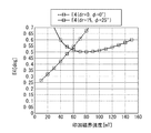
図17と図19から分かるように、第1の手段と第2の手段をそれぞれ単独で用いることにより、E4の磁界強度依存性を変化させることができる。しかし、第1の手段と第2の手段をそれぞれ単独で用いた場合には、印加磁界強度の広い範囲でE4の変動量を十分に小さくすることは難しい。そのため、第1の手段と第2の手段をそれぞれ単独で用いた場合には、本実施の形態に係る磁気センサ1の特性、すなわち、印加磁界強度が、20〜150mTの範囲の一部である副範囲であって、上限と下限の差が30mT以上である副範囲内で変化するときのE4の変動量は0.1°以下であるという特性を実現することが困難になる場合がある。
As can be seen from FIGS. 17 and 19, the magnetic field strength dependence of E4 can be changed by using the first means and the second means independently. However, when the first means and the second means are each used alone, it is difficult to sufficiently reduce the variation amount of E4 in a wide range of the applied magnetic field strength. Therefore, when each of the first means and the second means is used alone, the characteristics of the
これに対し、第1の手段と第2の手段を組み合わせて用いると、第1の手段と第2の手段をそれぞれ単独で用いた場合に比べて、印加磁界強度の広い範囲でE4の変動量を十分に小さくすることが可能になり、その結果、容易に、上記の本実施の形態に係る磁気センサ1の特性を実現することが可能になる。
On the other hand, when the first means and the second means are used in combination, the variation amount of E4 in a wider range of the applied magnetic field strength compared to the case where the first means and the second means are each used alone. Can be made sufficiently small, and as a result, the characteristics of the
以下、本実施の形態に係る磁気センサ1の第1ないし第3の実施例と、比較例の磁気センサについて説明する。第1ないし第3の実施例は、いずれも、第1の手段と第2の手段を組み合わせて用いた例である。比較例の磁気センサは、自由層51の第2の面の形状を、drがゼロである形状とし、且つオフセット角度φを0°とした例である。
Hereinafter, first to third examples of the
[第1の実施例]
第1の実施例の磁気センサ1は、自由層51の第2の面の形状を、drが1%、αが0°である形状とし、且つオフセット角度φを25°としたものである。図20は、第1の実施例の磁気センサ1と比較例の磁気センサにおけるV3r,V5rのそれぞれの磁界強度依存性を示す特性図である。図21は、第1の実施例の磁気センサ1と比較例の磁気センサにおけるE4の磁界強度依存性を示す特性図である。図20では、第1の実施例の磁気センサ1におけるV3r,V5rをV3r(dr=1%,φ=25°),V5r(dr=1%,φ=25°)と表記し、比較例の磁気センサにおけるV3r,V5rをV3r(dr=0,φ=0°),V5r(dr=0,φ=0°)と表記している。また、図21では、第1の実施例の磁気センサ1におけるE4をE4(dr=1%,φ=25°)と表記し、比較例の磁気センサにおけるE4をE4(dr=0,φ=0°)と表記している。
[First embodiment]
In the
図20および図21に示したように、第1の実施例の磁気センサ1では、印加磁界強度が40〜150mTの範囲において、V3rとV5rの差の絶対値の変動量が0.18%以下であり、E4の変動量は0.1°以下である。また、第1の実施例の磁気センサ1では、印加磁界強度が50〜120mTの範囲において、V3rとV5rの差の絶対値の変動量が0.09%以下であり、E4の変動量は0.05°以下である。第1の実施例の磁気センサ1は、本実施の形態に係る磁気センサ1の特性の要件を満たしている。一方、比較例の磁気センサは、本実施の形態に係る磁気センサ1の特性の要件を満たしていない。
As shown in FIGS. 20 and 21, in the
ここで、図4に示した演算部30の補正処理部32における補正処理の第1の例と第2の例について説明する。
Here, a first example and a second example of correction processing in the
補正処理の第1の例では、磁気センサ1の出荷前に、以下のような試験を行って、補正情報保持部33に格納する補正情報を作成する。試験では、印加磁界強度を副範囲内の特定の値にする。そして、被検出磁界MFの方向DMが基準方向DRに対してなす角度θを、0°〜360°の範囲内において等間隔で変化させて、複数の角度θにおいて、角度検出値算出部31によって算出される角度検出値θsを取得すると共に、角度検出値θsの誤差である角度誤差を求める。以下、角度誤差を記号AEで表す。
In the first example of the correction process, the following test is performed before the
角度誤差AEは、角度θの周期の1/4の周期で変化する。角度誤差AEの主成分は、角度誤差4次成分である。ここで、角度検出値θsを取得する複数の角度θの数をmとする。補正情報を作成するためには、標本化定理から、mは8以上の整数である必要がある。角度検出値θsを取得する複数の角度θには0°を含めることが好ましく、その場合には、mを16以上の整数とする。 The angle error AE changes at a cycle that is 1/4 of the cycle of the angle θ. The main component of the angle error AE is an angular error quaternary component. Here, m is the number of the plurality of angles θ for obtaining the detected angle value θs. In order to create correction information, m needs to be an integer of 8 or more from the sampling theorem. It is preferable that 0 ° is included in the plurality of angles θ for obtaining the angle detection value θs, and in this case, m is an integer of 16 or more.
ここで、角度検出値θsを取得するときの角度θをθnと表す。nは、1以上m以下の整数である。また、θnに対応する角度検出値θsをθsnと表し、θnに対応する角度誤差AEをAEnと表す。また、θsnとAEnの組み合わせを(θsn,AEn)と表す。試験では、この(θsn,AEn)を補正情報として、補正情報保持部33に格納する。
Here, the angle θ when the detected angle value θs is obtained is represented as θn. n is an integer of 1 to m. Further, the detected angle value θs corresponding to θn is expressed as θsn, and the angle error AE corresponding to θn is expressed as AEn. A combination of θsn and AEn is represented as (θsn, AEn). In the test, (θsn, AEn) is stored in the correction
磁気センサ1の使用時には、補正処理部32は、補正情報(θsn,AEn)に基づいて、線形補間を用いて、入力された角度検出値θsに対する補正後角度検出値θtを求める。より具体的に説明すると、補正処理部32は、入力された角度検出値θsの前後のθsnに対応する2つの補正情報(θsn,AEn)に基づいて、線形補間を用いて、入力された角度検出値θsに対応する近似角度誤差AEsを求め、θsからAEsを引いた値を補正後角度検出値θtとする。近似角度誤差AEsは、入力された角度検出値θsが特定のθsnと一致するときは特定のθsnに対応する角度誤差AEnであり、入力された角度検出値θsがθsn以外のときは線形補間によって推定された角度誤差である。
When the
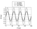
以下、第1の実施例を例にとって、補正処理の第1の例について、より具体的に説明する。ここでは、印加磁界強度の50〜120mTの範囲を副範囲とする。図22は、第1の実施例において、印加磁界強度がそれぞれ20mT、80mT、150mTのときの角度θと角度検出値θsの角度誤差AEとの関係を示している。図22において、横軸は角度θを示し、縦軸は角度誤差AEを示している。図22では、印加磁界強度が20mT、80mT、150mTのときの角度誤差AEを、AE(20mT),AE(80mT),AE(150mT)と表記している。なお、印加磁界強度が50〜120mTの範囲内のときの角度θと角度誤差AEとの関係はほぼ同じである。そのため、図22に示した印加磁界強度が80mTのときの角度θと角度誤差AEとの関係は、印加磁界強度が50〜120mTの範囲内のときの角度θと角度誤差AEとの関係を代表して表していると言える。 Hereinafter, the first example of the correction process will be described more specifically with reference to the first example. Here, the range of 50 to 120 mT of the applied magnetic field strength is set as the sub-range. FIG. 22 shows the relationship between the angle θ and the angle error AE of the detected angle value θs when the applied magnetic field strength is 20 mT, 80 mT, and 150 mT, respectively, in the first embodiment. In FIG. 22, the horizontal axis represents the angle θ, and the vertical axis represents the angle error AE. In FIG. 22, the angle error AE when the applied magnetic field intensity is 20 mT, 80 mT, and 150 mT is expressed as AE (20 mT), AE (80 mT), and AE (150 mT). The relationship between the angle θ and the angle error AE when the applied magnetic field strength is in the range of 50 to 120 mT is substantially the same. Therefore, the relationship between the angle θ and the angle error AE when the applied magnetic field strength is 80 mT shown in FIG. 22 is representative of the relationship between the angle θ and the angle error AE when the applied magnetic field strength is in the range of 50 to 120 mT. It can be said that.
ここでは、一例として、前述の磁気センサ1の出荷前の試験において、印加磁界強度を50mTとし、角度検出値θsを取得する複数の角度θnの数mを32とする。nが1のときのθnは0°である。また、θnとAEnの組み合わせを(θn,AEn)と表す。試験では、(θn,AEn)の情報が得られる。図23は、この(θn,AEn)の情報に基づいて、線形補間を用いて作成された角度θと推定角度誤差AEeとの関係を示している。図23において、横軸は角度θを示し、縦軸は推定角度誤差AEeを示している。推定角度誤差AEeは、角度θがθnのときはAEnであり、角度θがθn以外のときは線形補間によって推定された角度誤差である。図23に示したθとAEeとの関係を表す特性線は、(θn,AEn)を頂点とした折れ線である。
Here, as an example, in the test before shipment of the
補正処理の第1の例では、試験によって得られた(θn,AEn)の情報に基づいて、前述の補正情報(θsn,AEn)を作成し、これを補正情報保持部33に格納する。磁気センサ1の使用時には、補正処理部32は、前述の通り、入力された角度検出値θsに対応する補正後角度検出値θtを求める。ここで、補正後角度検出値θtの誤差を補正後角度誤差CAEと定義する。
In the first example of the correction process, the above-described correction information (θsn, AEn) is created based on the information (θn, AEn) obtained by the test, and stored in the correction
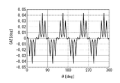
図24は、一例として、印加磁界強度が80mTのときの角度θと補正後角度誤差CAEとの関係を示している。図24において、横軸は角度θを示し、縦軸は補正後角度誤差CAEを示している。図24に示したように、印加磁界強度が80mTのときの補正後角度誤差CAEの絶対値の最大値は、0.05°以下であり、図22に示した印加磁界強度が80mTのときの角度誤差AEの絶対値の最大値に比べて大幅に小さくなっている。 FIG. 24 shows, as an example, the relationship between the angle θ and the corrected angle error CAE when the applied magnetic field strength is 80 mT. In FIG. 24, the horizontal axis represents the angle θ, and the vertical axis represents the corrected angle error CAE. As shown in FIG. 24, the maximum absolute value of the corrected angle error CAE when the applied magnetic field strength is 80 mT is 0.05 ° or less, and when the applied magnetic field strength shown in FIG. 22 is 80 mT. It is significantly smaller than the maximum absolute value of the angle error AE.
ここで、補正後角度誤差CAEの最大値と最小値の差の1/2を補正後角度誤差CAEの振幅と定義する。補正後角度誤差CAEの振幅は、補正後角度誤差CAEの絶対値の最大値以下になる。従って、図24に示した例では、印加磁界強度が80mTのときの補正後角度誤差CAEの振幅は、0.05°以下である。 Here, ½ of the difference between the maximum value and the minimum value of the corrected angle error CAE is defined as the amplitude of the corrected angle error CAE. The amplitude of the corrected angle error CAE is equal to or less than the maximum absolute value of the corrected angle error CAE. Therefore, in the example shown in FIG. 24, the amplitude of the corrected angle error CAE when the applied magnetic field strength is 80 mT is 0.05 ° or less.
補正処理部32では、印加磁界強度が副範囲内のどの値であっても補正後角度誤差CAEの振幅が0.1°以下になるように補正処理を行うことが好ましく、印加磁界強度が副範囲内のどの値であっても補正後角度誤差CAEの振幅が0.05°以下になるように補正処理を行うことがより好ましい。
The
図25は、副範囲50〜120mTにおける印加磁界強度と補正後角度誤差CAEの振幅との関係を示している。図25において、横軸は印加磁界強度を示し、縦軸は補正後角度誤差CAEの振幅を示している。図25に示したように、副範囲50〜120mTにおいて、補正後角度誤差CAEの振幅は0.05°以下である。 FIG. 25 shows the relationship between the applied magnetic field strength and the amplitude of the corrected angle error CAE in the sub-range 50 to 120 mT. In FIG. 25, the horizontal axis indicates the applied magnetic field strength, and the vertical axis indicates the amplitude of the corrected angle error CAE. As shown in FIG. 25, in the sub-range 50 to 120 mT, the amplitude of the corrected angle error CAE is 0.05 ° or less.
前述のように、角度誤差AEの主成分は角度誤差4次成分である。前述の近似角度誤差AEsは、角度誤差4次成分に非常に近い。補正処理の第1の例によれば、角度検出値θsから近似角度誤差AEsを引いて補正後角度検出値θtを生成するため、角度θの周期の1/4の周期の誤差成分をほとんど含まない補正後角度検出値θtを生成することができる。また、このことから、補正処理の第1の例によれば、副範囲内におけるE4の変動量が0.1°以下であれば、副範囲内における補正後角度誤差CAEの振幅を0.1°以下にすることができ、副範囲内におけるE4の変動量が0.05°以下であれば、副範囲内における補正後角度誤差CAEの振幅を0.05°以下にすることができる。 As described above, the main component of the angle error AE is the angular error quaternary component. The approximate angle error AEs described above is very close to the quaternary component of the angle error. According to the first example of the correction process, the approximated angle error AEs is subtracted from the detected angle value θs to generate the corrected detected angle value θt, and therefore almost includes an error component having a period that is ¼ of the period of the angle θ. It is possible to generate the detected angle detection value θt without correction. Therefore, according to the first example of the correction process, if the variation amount of E4 in the sub-range is 0.1 ° or less, the amplitude of the post-correction angle error CAE in the sub-range is 0.1. If the variation amount of E4 within the sub-range is 0.05 ° or less, the amplitude of the corrected angle error CAE within the sub-range can be 0.05 ° or less.
次に、補正処理部32における補正処理の第2の例について説明する。補正処理の第2の例では、磁気センサ1の出荷前に、補正処理の第1の例の場合と同様の試験を行って、角度θを0°〜360°の範囲内において等間隔で変化させて、複数の角度θにおける角度誤差AEを求める。そして、角度誤差AEの最大値と最小値の差の1/2と定義される角度誤差AEの振幅Fを求める。試験では、この振幅Fを補正情報として、補正情報保持部33に格納する。
Next, a second example of correction processing in the
磁気センサ1の使用時には、補正処理部32は、補正情報Fを含む次の式(4)によって、入力された角度検出値θsに対応する補正後角度検出値θtを求める。
When the
θt=θs−Fsin4θs …(4) θt = θs−Fsin4θs (4)
式(4)中の「Fsin4θs」は、補正処理の第1の例における近似角度誤差AEsに対応する。補正処理の第1の例と同様に、補正処理の第2の例によっても、副範囲内におけるE4の変動量が0.1°以下であれば、副範囲内における補正後角度誤差CAEの振幅を0.1°以下にすることができ、副範囲内におけるE4の変動量が0.05°以下であれば、副範囲内における補正後角度誤差CAEの振幅を0.05°以下にすることができる。 “Fsin4θs” in Expression (4) corresponds to the approximate angle error AEs in the first example of the correction process. Similar to the first example of the correction process, according to the second example of the correction process, if the variation amount of E4 within the sub-range is 0.1 ° or less, the amplitude of the corrected angle error CAE within the sub-range is as follows. If the variation amount of E4 within the sub-range is 0.05 ° or less, the amplitude of the corrected angle error CAE within the sub-range should be 0.05 ° or less. Can do.
なお、補正処理の内容は、上記の第1および第2の例に限らず、角度θの周期の1/4の周期の誤差成分をほとんど含まない補正後角度検出値θtを生成できるものであればよい。 Note that the content of the correction process is not limited to the first and second examples described above, and the corrected angle detection value θt that hardly includes an error component having a period of ¼ of the period of the angle θ can be generated. That's fine.
[第2の実施例]
第2の実施例の磁気センサ1は、自由層51の第2の面の形状を、drが0.1%、αが0°である形状とし、且つオフセット角度φを10°としたものである。図26は、第2の実施例の磁気センサ1と比較例の磁気センサにおけるV3r,V5rのそれぞれの磁界強度依存性を示す特性図である。図27は、第2の実施例の磁気センサ1と比較例の磁気センサにおけるE4の磁界強度依存性を示す特性図である。図26では、第2の実施例の磁気センサ1におけるV3r,V5rをV3r(dr=0.1%,φ=10°),V5r(dr=0.1%,φ=10°)と表記し、比較例の磁気センサにおけるV3r,V5rをV3r(dr=0,φ=0°),V5r(dr=0,φ=0°)と表記している。また、図27では、第2の実施例の磁気センサ1におけるE4をE4(dr=0.1%,φ=10°)と表記し、比較例の磁気センサにおけるE4をE4(dr=0,φ=0°)と表記している。
[Second Embodiment]
In the
図26および図27に示したように、第2の実施例の磁気センサ1では、印加磁界強度が20〜70mTの範囲において、V3rとV5rの差の絶対値の変動量が0.18%以下であり、E4の変動量は0.1°以下である。また、第2の実施例の磁気センサ1では、印加磁界強度が25〜55mTの範囲において、V3rとV5rの差の絶対値の変動量が0.09%以下であり、E4の変動量は0.05°以下である。第2の実施例の磁気センサ1は、本実施の形態に係る磁気センサ1の特性の要件を満たしている。
As shown in FIGS. 26 and 27, in the
[第3の実施例]
第3の実施例の磁気センサ1は、自由層51の第2の面の形状を、drが1%、αが0°である形状とし、且つオフセット角度φを30°としたものである。図28は、第3の実施例の磁気センサ1と比較例の磁気センサにおけるV3r,V5rのそれぞれの磁界強度依存性を示す特性図である。図29は、第3の実施例の磁気センサ1と比較例の磁気センサにおけるE4の磁界強度依存性を示す特性図である。図28では、第3の実施例の磁気センサ1におけるV3r,V5rをV3r(dr=1%,φ=30°),V5r(dr=1%,φ=30°)と表記し、比較例の磁気センサにおけるV3r,V5rをV3r(dr=0,φ=0°),V5r(dr=0,φ=0°)と表記している。また、図29では、第3の実施例の磁気センサ1におけるE4をE4(dr=1%,φ=30°)と表記し、比較例の磁気センサにおけるE4をE4(dr=0,φ=0°)と表記している。
[Third embodiment]
In the
図28および図29に示したように、第3の実施例の磁気センサ1では、印加磁界強度が50〜150mTの範囲において、V3rとV5rの差の絶対値の変動量が0.18%以下であり、E4の変動量は0.1°以下である。また、第3の実施例の磁気センサ1では、印加磁界強度が60〜150mTの範囲において、V3rとV5rの差の絶対値の変動量が0.09%以下であり、E4の変動量は0.05°以下である。第3の実施例の磁気センサ1は、本実施の形態に係る磁気センサ1の特性の要件を満たしている。
As shown in FIGS. 28 and 29, in the
第1ないし第3の実施例から、自由層51の第2の面の形状を規定するためのdr,αの値と、オフセット角度φの値を変えることによって、上限と下限の差が30mT以上であって、E4の変動量が0.1°以下という要件を満たす副範囲を、20〜150mTの範囲内で移動させることが可能であることが分かる。
From the first to third embodiments, by changing the values of dr and α for defining the shape of the second surface of the
以上説明したように、本実施の形態に係る磁気センサ1は、印加磁界強度が、20〜150mTの範囲の一部である副範囲であって、上限と下限の差が30mT以上である副範囲内で変化するときのE4の変動量は0.1°以下であるという要件を満たすものである。これにより、本実施の形態に係る磁気センサ1によれば、印加磁界強度の広い範囲で角度誤差の変動量を小さくすることができる。
As described above, the
本実施の形態において、副範囲内において、角度誤差AEの絶対値の最大値が、例えば0.1°以下あるいは0.05°以下のように十分に小さい場合には、演算部30は、磁気センサ1によって検出された角度θの値として、角度検出値θsを出力してもよい。この場合には、演算部30は、補正処理部32と補正情報保持部33を含まなくてもよい。
In the present embodiment, when the maximum value of the absolute value of the angle error AE is sufficiently small, for example, 0.1 ° or less or 0.05 ° or less within the sub-range, the
本実施の形態では、副範囲内において、角度誤差AEの絶対値の最大値が、例えば0.1°を超えるように大きい場合であっても、補正処理部32によって、印加磁界強度に応じて異なることのない補正処理を行うことによって、副範囲内において、補正後角度検出値θtの誤差である補正後角度誤差CAEの絶対値の最大値を小さくすることができる。
In the present embodiment, even if the maximum value of the absolute value of the angle error AE is large, for example, exceeding 0.1 ° within the sub-range, the
なお、本実施の形態に係る磁気センサ1の特性の要件を満たすために必要なdr,α,φの各値は、MR素子50の構成等によって変わり得る。従って、dr,α,φの各値は、MR素子50の構成や、副範囲を規定する印加磁界強度の上限および下限の値に応じて、適宜選択される。
It should be noted that the values of dr, α, and φ necessary for satisfying the requirements of the characteristics of the
副範囲は、広いほどよい。そのため、副範囲の広さを規定する副範囲の上限と下限の差は、40mT以上であることが好ましく、50mT以上であることがより好ましい。ここで、副範囲の上限と下限の差が30mT以上であることを、副範囲の最低限の要件と言い、副範囲の上限と下限の差が40mT以上であることを、副範囲の好ましい要件と言い、副範囲の上限と下限の差が50mT以上であることを、副範囲のより好ましい要件と言う。 The wider the subrange, the better. Therefore, the difference between the upper limit and the lower limit of the subrange that defines the width of the subrange is preferably 40 mT or more, and more preferably 50 mT or more. Here, the difference between the upper limit and the lower limit of the sub-range is 30 mT or more is called the minimum requirement of the sub-range, and the difference between the upper limit and the lower limit of the sub-range is 40 mT or more, the preferable requirement of the sub-range It is said that the difference between the upper limit and the lower limit of the subrange is 50 mT or more as a more preferable requirement of the subrange.
また、副範囲内におけるE4の変動量は、小さいほどよく、0.05°以下であることが好ましい。ここで、副範囲内におけるE4の変動量が0.1°以下であることを、E4の最低限の要件と言い、副範囲内におけるE4の変動量が0.05°以下であることを、E4の好ましい要件と言う。 Further, the variation amount of E4 within the sub-range is preferably as small as possible and is preferably 0.05 ° or less. Here, the variation amount of E4 within the sub-range is 0.1 ° or less is called the minimum requirement of E4, and the variation amount of E4 within the sub-range is 0.05 ° or less. This is a preferable requirement for E4.
前述のように、副範囲内におけるV3rとV5rの差の絶対値の変動量が0.18%以下であれば、副範囲内におけるE4の変動量は0.1°以下になる。そのため、E4の最低限の要件を満たすためには、副範囲内におけるV3rとV5rの差の絶対値の変動量は0.18%以下であることが好ましい。また、副範囲内におけるV3rとV5rの差の絶対値の変動量が0.09%以下であれば、副範囲内におけるE4の変動量は0.05°以下になる。そのため、E4の好ましい要件を満たすためには、副範囲内におけるV3rとV5rの差の絶対値の変動量は0.09%以下であることが好ましい。 As described above, if the variation amount of the absolute value of the difference between V3r and V5r within the sub-range is 0.18% or less, the variation amount of E4 within the sub-range is 0.1 ° or less. Therefore, in order to satisfy the minimum requirement of E4, it is preferable that the fluctuation amount of the absolute value of the difference between V3r and V5r within the sub-range is 0.18% or less. Further, if the variation amount of the absolute value of the difference between V3r and V5r within the sub-range is 0.09% or less, the variation amount of E4 within the sub-range is 0.05 ° or less. Therefore, in order to satisfy the preferable requirement of E4, it is preferable that the fluctuation amount of the absolute value of the difference between V3r and V5r within the subrange is 0.09% or less.
第1の実施例の磁気センサ1と第3の実施例の磁気センサ1は、副範囲の最低限の要件、好ましい要件およびより好ましい要件のいずれかと、E4の最低限の要件および好ましい要件のいずれかとを任意に組み合わせた条件を全て満たしている。第2の実施例の磁気センサ1は、副範囲の最低限の要件、好ましい要件およびより好ましい要件のいずれかとE4の最低限の要件とを組み合わせた条件と、副範囲の最低限の要件とE4の好ましい要件とを組み合わせた条件とを満たしている。
The
なお、本発明は、上記実施の形態に限定されず、種々の変更が可能である。例えば、自由層51の第2の面の形状を4回対称形状とする場合、第2の面の外縁51aの形状は、r(θa)が式(3)で表される形状に限らない。例えば、第2の面の外縁51aの形状は、r(θa)が三角波形状に変化する形状であってもよい。
In addition, this invention is not limited to the said embodiment, A various change is possible. For example, when the shape of the second surface of the
1…磁気センサ、2…磁界発生部、3…磁界検出部、10,20…検出回路、14,24…ブリッジ回路、30…演算部、31…角度検出値算出部、32…補正処理部、33…補正情報保持部、50…MR素子、51…自由層、52…非磁性層、53…固定層。
DESCRIPTION OF
なお、図16および図17は、歪み比率drと歪み方向αの少なくとも一方を変えたときのV3r,V5r,E4の磁界強度依存性の変化の仕方の傾向を説明するために示した一例である。図16および図17には示していないが、αを一定にしてdrを変化させると、drが大きくなるほど、以下で説明する傾向のV3r,V5r,E4の磁界強度依存性の変化が顕著に現れ、drが小さくなるほど、V3r,V5r,E4の磁界強度依存性は、それぞれdrがゼロである場合におけるV3r,V5r,E4の磁界強度依存性に近づく。
16 and 17 are examples shown for explaining the tendency of the change in the magnetic field strength dependency of V3r, V5r, and E4 when at least one of the strain ratio dr and the strain direction α is changed. . Although not shown in FIGS. 16 and 17, when dr is changed while α is constant, the change in the magnetic field strength dependence of V3r, V5r, and E4, which tends to be described below, becomes more prominent as dr increases. As dr decreases, the magnetic field strength dependence of V3r, V5r, and E4 approaches the magnetic field strength dependence of V3r, V5r, and E4 when dr is zero, respectively.
Claims (10)
磁界検出部と演算部とを備え、
前記磁界検出部は、前記被検出磁界を検出する複数の磁気抵抗効果素子を含み、前記被検出磁界の方向が第1の方向に対してなす角度と対応関係を有する第1の信号と前記被検出磁界の方向が第2の方向に対してなす角度と対応関係を有する第2の信号とを出力し、
前記複数の磁気抵抗効果素子の各々は、磁化方向が固定された磁化固定層と、前記被検出磁界の方向に応じて磁化の方向が変化する自由層と、前記磁化固定層と自由層の間に配置された非磁性層とを有し、
前記演算部は、前記第1および第2の信号に基づいて前記角度検出値を算出し、
前記被検出磁界の方向が所定の周期で回転する場合、前記角度検出値は、前記所定の周期の1/4の周期で変化する角度誤差成分を含み、
前記磁界検出部における前記被検出磁界の強度が、20〜150mTの範囲の一部である副範囲であって、上限と下限の差が30mT以上である副範囲内で変化するときの前記角度誤差成分の絶対値の最大値の変動量は、0.1°以下であることを特徴とする磁気センサ。 A magnetic sensor for generating an angle detection value having a correspondence relationship with an angle formed by a direction of a detected magnetic field at a reference position with respect to a reference direction,
A magnetic field detection unit and a calculation unit;
The magnetic field detection unit includes a plurality of magnetoresistive elements that detect the detected magnetic field, and the first signal having a correspondence relationship with the angle formed by the direction of the detected magnetic field with respect to the first direction and the detected signal Outputting a second signal having a correspondence relationship with an angle formed by the direction of the detected magnetic field with respect to the second direction;
Each of the plurality of magnetoresistive elements includes a magnetization fixed layer whose magnetization direction is fixed, a free layer whose magnetization direction changes according to the direction of the detected magnetic field, and between the magnetization fixed layer and the free layer A non-magnetic layer disposed on
The calculation unit calculates the angle detection value based on the first and second signals,
When the direction of the detected magnetic field rotates at a predetermined period, the angle detection value includes an angle error component that changes at a quarter of the predetermined period;
The angle error when the intensity of the magnetic field to be detected in the magnetic field detection unit is a sub-range that is a part of a range of 20 to 150 mT and the difference between the upper limit and the lower limit changes within a sub-range that is 30 mT or more. A magnetic sensor characterized in that the fluctuation amount of the maximum absolute value of the component is 0.1 ° or less.
前記第1の理想成分が最大値をとるときの前記第1の理想成分に対する前記第1の第3高調波成分の比率を第1の比率とし、前記第1の理想成分が最大値をとるときの前記第1の理想成分に対する前記第1の第5高調波成分の比率を第2の比率とし、前記第2の理想成分が最大値をとるときの前記第2の理想成分に対する前記第2の第3高調波成分の比率を第3の比率とし、前記第2の理想成分が最大値をとるときの前記第2の理想成分に対する前記第2の第5高調波成分の比率を第4の比率とし、前記第1の比率と前記第3の比率の平均値を第3高調波成分比率とし、前記第2の比率と前記第4の比率の平均値を第5高調波成分比率としたときに、前記磁界検出部における前記被検出磁界の強度が前記副範囲内で変化するときの前記第3高調波成分比率と前記第5高調波成分比率との差の絶対値の変動量が0.18%以下であることを特徴とする請求項1記載の磁気センサ。 When the direction of the detected magnetic field rotates at the predetermined period, the first signal is a first ideal component that periodically changes to draw an ideal sine curve, and the first ideal component. A first third harmonic component that is an error component corresponding to the third harmonic with respect to and a first fifth harmonic component that is an error component corresponding to the fifth harmonic with respect to the first ideal component. And the second signal is a second ideal component that periodically changes to draw an ideal sine curve, and an error component corresponding to a third harmonic with respect to the second ideal component. And a second fifth harmonic component that is an error component corresponding to the fifth harmonic with respect to the second ideal component,
When the ratio of the first third harmonic component to the first ideal component when the first ideal component takes the maximum value is the first ratio, and the first ideal component takes the maximum value The ratio of the first fifth harmonic component to the first ideal component is a second ratio, and the second ideal component with respect to the second ideal component when the second ideal component takes a maximum value. The ratio of the third harmonic component is the third ratio, and the ratio of the second fifth harmonic component to the second ideal component when the second ideal component takes the maximum value is the fourth ratio. And an average value of the first ratio and the third ratio is a third harmonic component ratio, and an average value of the second ratio and the fourth ratio is a fifth harmonic component ratio. The third high level when the strength of the detected magnetic field in the magnetic field detecting unit changes within the sub-range. The magnetic sensor according to claim 1, wherein the amount of fluctuation of the absolute value of the difference between the a wave component ratios fifth harmonic component ratio is less than 0.18%.
前記第1の理想成分が最大値をとるときの前記第1の理想成分に対する前記第1の第3高調波成分の比率を第1の比率とし、前記第1の理想成分が最大値をとるときの前記第1の理想成分に対する前記第1の第5高調波成分の比率を第2の比率とし、前記第2の理想成分が最大値をとるときの前記第2の理想成分に対する前記第2の第3高調波成分の比率を第3の比率とし、前記第2の理想成分が最大値をとるときの前記第2の理想成分に対する前記第2の第5高調波成分の比率を第4の比率とし、前記第1の比率と前記第3の比率の平均値を第3高調波成分比率とし、前記第2の比率と前記第4の比率の平均値を第5高調波成分比率としたときに、前記磁界検出部における前記被検出磁界の強度が前記副範囲内で変化するときの前記第3高調波成分比率と前記第5高調波成分比率との差の絶対値の変動量が0.09%以下であることを特徴とする請求項5記載の磁気センサ。 When the direction of the detected magnetic field rotates at the predetermined period, the first signal is a first ideal component that periodically changes to draw an ideal sine curve, and the first ideal component. A first third harmonic component that is an error component corresponding to the third harmonic with respect to and a first fifth harmonic component that is an error component corresponding to the fifth harmonic with respect to the first ideal component. And the second signal is a second ideal component that periodically changes to draw an ideal sine curve, and an error component corresponding to a third harmonic with respect to the second ideal component. And a second fifth harmonic component that is an error component corresponding to the fifth harmonic with respect to the second ideal component,
When the ratio of the first third harmonic component to the first ideal component when the first ideal component takes the maximum value is the first ratio, and the first ideal component takes the maximum value The ratio of the first fifth harmonic component to the first ideal component is a second ratio, and the second ideal component with respect to the second ideal component when the second ideal component takes a maximum value. The ratio of the third harmonic component is the third ratio, and the ratio of the second fifth harmonic component to the second ideal component when the second ideal component takes the maximum value is the fourth ratio. And an average value of the first ratio and the third ratio is a third harmonic component ratio, and an average value of the second ratio and the fourth ratio is a fifth harmonic component ratio. The third high level when the strength of the detected magnetic field in the magnetic field detecting unit changes within the sub-range. The magnetic sensor according to claim 5, wherein the amount of fluctuation of the absolute value of the difference between the a wave component ratios fifth harmonic component ratio is less than 0.09%.
前記第1の検出回路と前記第2の検出回路の各々は、前記複数の磁気抵抗効果素子のうちの2つ以上が直列に接続されて構成された磁気抵抗効果素子列を含み、
前記複数の磁気抵抗効果素子の各々の前記自由層は、前記非磁性層に接する第1の面と、その反対側の第2の面とを有し、前記第2の面は、5回以上の回転対称とはならない4回対称の回転対称形状を有し、
前記磁気抵抗効果素子列を構成する2つ以上の磁気抵抗効果素子の数は、偶数であり、
前記磁気抵抗効果素子列を構成する2つ以上の磁気抵抗効果素子は、磁気抵抗効果素子の対を1つ以上含み、
前記対を構成する2つの磁気抵抗効果素子における磁化固定層の磁化方向は、0°および180°を除く所定の相対角度をなし、
前記第1の検出回路において、前記第1の方向は、前記対を構成する2つの磁気抵抗効果素子における磁化固定層の磁化方向の中間の方向またはそれとは反対の方向であり、
前記第2の検出回路において、前記第2の方向は、前記対を構成する2つの磁気抵抗効果素子における磁化固定層の磁化方向の中間の方向またはそれとは反対の方向であることを特徴とする請求項1ないし9のいずれかに記載の磁気センサ。 The magnetic field detection unit includes a first detection circuit that outputs the first signal, and a second detection circuit that outputs the second signal,
Each of the first detection circuit and the second detection circuit includes a magnetoresistive effect element array configured by connecting two or more of the plurality of magnetoresistive effect elements in series,
The free layer of each of the plurality of magnetoresistive elements has a first surface in contact with the nonmagnetic layer and a second surface opposite to the first surface, and the second surface is 5 times or more. Having a four-fold rotational symmetry shape that is not rotationally symmetric,
The number of the two or more magnetoresistive elements constituting the magnetoresistive element array is an even number,
The two or more magnetoresistive elements constituting the magnetoresistive element array include one or more pairs of magnetoresistive elements,
The magnetization direction of the magnetization fixed layer in the two magnetoresistive elements constituting the pair has a predetermined relative angle excluding 0 ° and 180 °,
In the first detection circuit, the first direction is an intermediate direction of the magnetization direction of the magnetization fixed layer in the two magnetoresistive effect elements constituting the pair or a direction opposite thereto.
In the second detection circuit, the second direction is an intermediate direction of the magnetization direction of the magnetization fixed layer in the two magnetoresistive elements constituting the pair or a direction opposite thereto. The magnetic sensor according to claim 1.
Priority Applications (2)
| Application Number | Priority Date | Filing Date | Title |
|---|---|---|---|
| JP2015045477A JP6191838B2 (en) | 2015-03-09 | 2015-03-09 | Magnetic sensor |
| DE102016104285.4A DE102016104285B4 (en) | 2015-03-09 | 2016-03-09 | magnetic sensor |
Applications Claiming Priority (1)
| Application Number | Priority Date | Filing Date | Title |
|---|---|---|---|
| JP2015045477A JP6191838B2 (en) | 2015-03-09 | 2015-03-09 | Magnetic sensor |
Publications (2)
| Publication Number | Publication Date |
|---|---|
| JP2016166741A true JP2016166741A (en) | 2016-09-15 |
| JP6191838B2 JP6191838B2 (en) | 2017-09-06 |
Family
ID=56801290
Family Applications (1)
| Application Number | Title | Priority Date | Filing Date |
|---|---|---|---|
| JP2015045477A Active JP6191838B2 (en) | 2015-03-09 | 2015-03-09 | Magnetic sensor |
Country Status (2)
| Country | Link |
|---|---|
| JP (1) | JP6191838B2 (en) |
| DE (1) | DE102016104285B4 (en) |
Cited By (8)
| Publication number | Priority date | Publication date | Assignee | Title |
|---|---|---|---|---|
| JP2018054584A (en) * | 2016-09-30 | 2018-04-05 | Tdk株式会社 | Angle sensor and angle sensor system |
| JP6331177B1 (en) * | 2017-03-24 | 2018-05-30 | Tdk株式会社 | Angle sensor system |
| JP6331176B1 (en) * | 2017-03-24 | 2018-05-30 | Tdk株式会社 | Angle sensor system |
| WO2019151479A1 (en) * | 2018-02-02 | 2019-08-08 | 株式会社三共製作所 | Method and device for detecting positional change amount due to movement of moving body |
| US20200064416A1 (en) * | 2017-05-29 | 2020-02-27 | Panasonic Intellectual Property Management Co., Ltd. | Magnetic sensor |
| CN113532486A (en) * | 2020-04-20 | 2021-10-22 | Tdk株式会社 | Magnetic sensor, magnetic encoder, and lens detection device |
| CN113811738A (en) * | 2019-06-11 | 2021-12-17 | 株式会社村田制作所 | Magnetic sensor, magnetic sensor array, magnetic field distribution measuring device, and position specifying device |
| CN113960508A (en) * | 2020-07-21 | 2022-01-21 | Tdk株式会社 | Magnetic sensor |
Families Citing this family (10)
| Publication number | Priority date | Publication date | Assignee | Title |
|---|---|---|---|---|
| JP6288481B2 (en) | 2016-06-24 | 2018-03-07 | Tdk株式会社 | Angle sensor and angle sensor system |
| DE102017111895B3 (en) * | 2017-05-31 | 2018-07-05 | Schaeffler Technologies AG & Co. KG | Method for determining an angular position of a rotating component, in particular an electric motor for a clutch actuation system of a vehicle |
| DE102017222508B4 (en) * | 2017-12-12 | 2022-02-17 | Carl Zeiss Industrielle Messtechnik Gmbh | Method and device for correcting measurement system deviations |
| US11199424B2 (en) | 2018-01-31 | 2021-12-14 | Allegro Microsystems, Llc | Reducing angle error in a magnetic field angle sensor |
| US11175359B2 (en) | 2019-08-28 | 2021-11-16 | Allegro Microsystems, Llc | Reducing voltage non-linearity in a bridge having tunneling magnetoresistance (TMR) elements |
| WO2021041093A1 (en) * | 2019-08-28 | 2021-03-04 | Allegro Microsystems, Llc | Reducing angle error in a magnetic field angle sensor |
| US11467233B2 (en) | 2020-03-18 | 2022-10-11 | Allegro Microsystems, Llc | Linear bridges having nonlinear elements |
| US11408948B2 (en) | 2020-03-18 | 2022-08-09 | Allegro Microsystems, Llc | Linear bridge having nonlinear elements for operation in high magnetic field intensities |
| DE102021110733A1 (en) | 2021-04-27 | 2022-10-27 | Sensitec Gmbh | Magnetic field based angle sensor |
| DE102022125821A1 (en) | 2022-10-06 | 2024-04-11 | Tdk-Micronas Gmbh | COMPENSATION OF A HARMONIC |
Citations (6)
| Publication number | Priority date | Publication date | Assignee | Title |
|---|---|---|---|---|
| JPS63225124A (en) * | 1987-03-14 | 1988-09-20 | Hitachi Ltd | Magnetic position detector |
| US6433537B1 (en) * | 1998-10-28 | 2002-08-13 | Koninklijke Philips Electronics, N.V. | Arrangement for measuring a relative linear position between an angle sensor and magnetic body |
| JP2005214920A (en) * | 2004-02-02 | 2005-08-11 | Sankyo Seiki Mfg Co Ltd | Magnetic sensor |
| US20060290545A1 (en) * | 2005-05-31 | 2006-12-28 | Wolfgang Granig | Method for Determining Residual Error Compensation Parameters for a Magnetoresistive Angle Sensor and Method for Reducing a Residual Angle Error in a Magnetoresistive Angle Sensor |
| JP2012522238A (en) * | 2009-03-31 | 2012-09-20 | ヴァレオ エキプマン エレクトリク モトゥール | Method and apparatus for diagnosing functional failure of angular position measurement sensor of multiphase rotating electrical equipment |
| US20150066426A1 (en) * | 2013-08-27 | 2015-03-05 | Tdk Corporation | Rotating field sensor |
Family Cites Families (4)
| Publication number | Priority date | Publication date | Assignee | Title |
|---|---|---|---|---|
| US6633462B2 (en) | 2000-07-13 | 2003-10-14 | Koninklijke Philips Electronics N.V. | Magnetoresistive angle sensor having several sensing elements |
| JP5131339B2 (en) | 2010-11-17 | 2013-01-30 | Tdk株式会社 | Rotating magnetic field sensor |
| JP5590349B2 (en) | 2012-07-18 | 2014-09-17 | Tdk株式会社 | Magnetic sensor system |
| US20160177674A1 (en) * | 2013-08-27 | 2016-06-23 | Halliburton Energy Services, Inc. | Simulating Fluid Leak-Off and Flow-Back in a Fractured Subterranean Region |
-
2015
- 2015-03-09 JP JP2015045477A patent/JP6191838B2/en active Active
-
2016
- 2016-03-09 DE DE102016104285.4A patent/DE102016104285B4/en active Active
Patent Citations (6)
| Publication number | Priority date | Publication date | Assignee | Title |
|---|---|---|---|---|
| JPS63225124A (en) * | 1987-03-14 | 1988-09-20 | Hitachi Ltd | Magnetic position detector |
| US6433537B1 (en) * | 1998-10-28 | 2002-08-13 | Koninklijke Philips Electronics, N.V. | Arrangement for measuring a relative linear position between an angle sensor and magnetic body |
| JP2005214920A (en) * | 2004-02-02 | 2005-08-11 | Sankyo Seiki Mfg Co Ltd | Magnetic sensor |
| US20060290545A1 (en) * | 2005-05-31 | 2006-12-28 | Wolfgang Granig | Method for Determining Residual Error Compensation Parameters for a Magnetoresistive Angle Sensor and Method for Reducing a Residual Angle Error in a Magnetoresistive Angle Sensor |
| JP2012522238A (en) * | 2009-03-31 | 2012-09-20 | ヴァレオ エキプマン エレクトリク モトゥール | Method and apparatus for diagnosing functional failure of angular position measurement sensor of multiphase rotating electrical equipment |
| US20150066426A1 (en) * | 2013-08-27 | 2015-03-05 | Tdk Corporation | Rotating field sensor |
Cited By (15)
| Publication number | Priority date | Publication date | Assignee | Title |
|---|---|---|---|---|
| JP2018054584A (en) * | 2016-09-30 | 2018-04-05 | Tdk株式会社 | Angle sensor and angle sensor system |
| CN108627082B (en) * | 2017-03-24 | 2020-09-04 | Tdk株式会社 | Angle sensor system |
| JP6331177B1 (en) * | 2017-03-24 | 2018-05-30 | Tdk株式会社 | Angle sensor system |
| JP6331176B1 (en) * | 2017-03-24 | 2018-05-30 | Tdk株式会社 | Angle sensor system |
| CN108627082A (en) * | 2017-03-24 | 2018-10-09 | Tdk株式会社 | Angular transducer system |
| JP2018162994A (en) * | 2017-03-24 | 2018-10-18 | Tdk株式会社 | Angle sensor system |
| JP2018162995A (en) * | 2017-03-24 | 2018-10-18 | Tdk株式会社 | Angle sensor system |
| US20200064416A1 (en) * | 2017-05-29 | 2020-02-27 | Panasonic Intellectual Property Management Co., Ltd. | Magnetic sensor |
| WO2019151479A1 (en) * | 2018-02-02 | 2019-08-08 | 株式会社三共製作所 | Method and device for detecting positional change amount due to movement of moving body |
| JPWO2019151479A1 (en) * | 2018-02-02 | 2021-02-04 | 株式会社三共製作所 | Method and device for detecting the amount of position change due to the movement of a moving body |
| US11378604B2 (en) | 2018-02-02 | 2022-07-05 | Sankyo Seisakusho Co. | Method and device for detecting positional change amount due to movement of moving body |
| JP7190454B2 (en) | 2018-02-02 | 2022-12-15 | 株式会社三共製作所 | METHOD AND APPARATUS FOR DETECTING POSITION CHANGE BASED ON MOVEMENT OF MOBILE BODY |
| CN113811738A (en) * | 2019-06-11 | 2021-12-17 | 株式会社村田制作所 | Magnetic sensor, magnetic sensor array, magnetic field distribution measuring device, and position specifying device |
| CN113532486A (en) * | 2020-04-20 | 2021-10-22 | Tdk株式会社 | Magnetic sensor, magnetic encoder, and lens detection device |
| CN113960508A (en) * | 2020-07-21 | 2022-01-21 | Tdk株式会社 | Magnetic sensor |
Also Published As
| Publication number | Publication date |
|---|---|
| JP6191838B2 (en) | 2017-09-06 |
| DE102016104285A1 (en) | 2016-09-15 |
| DE102016104285B4 (en) | 2019-05-09 |
Similar Documents
| Publication | Publication Date | Title |
|---|---|---|
| JP6191838B2 (en) | Magnetic sensor | |
| JP5590349B2 (en) | Magnetic sensor system | |
| US8736256B2 (en) | Rotating field sensor | |
| JP6331177B1 (en) | Angle sensor system | |
| JP6288482B1 (en) | Angle sensor and angle sensor system | |
| US10648787B2 (en) | Rotating field sensor | |
| JP2011038855A (en) | Magnetic sensor | |
| JP5062454B2 (en) | Magnetic sensor | |
| US9200884B2 (en) | Magnetic sensor system including three detection circuits | |
| JP6331176B1 (en) | Angle sensor system | |
| JP6288481B2 (en) | Angle sensor and angle sensor system | |
| US20160169707A1 (en) | Rotating field sensor | |
| JP2012037467A (en) | Rotation magnetic sensor | |
| JP5928236B2 (en) | Rotating magnetic field sensor | |
| JP6395060B2 (en) | Angle sensor, correction method thereof, and angle sensor system | |
| JP6536632B2 (en) | Angle sensor and angle sensor system | |
| JP6066134B2 (en) | Magnetic sensor system | |
| JP2016166748A (en) | Magnetic sensor | |
| JP5812046B2 (en) | Rotating magnetic field sensor | |
| JP5928234B2 (en) | Rotating magnetic field sensor | |
| JP5365730B1 (en) | Rotating magnetic field sensor | |
| JP5062453B2 (en) | Magnetic sensor | |
| JP6784283B2 (en) | Angle sensor system | |
| JP5928235B2 (en) | Rotating magnetic field sensor | |
| JP6003371B2 (en) | Rotating magnetic field sensor |
Legal Events
| Date | Code | Title | Description |
|---|---|---|---|
| A977 | Report on retrieval |
Free format text: JAPANESE INTERMEDIATE CODE: A971007 Effective date: 20161226 |
|
| A131 | Notification of reasons for refusal |
Free format text: JAPANESE INTERMEDIATE CODE: A131 Effective date: 20170113 |
|
| A521 | Request for written amendment filed |
Free format text: JAPANESE INTERMEDIATE CODE: A523 Effective date: 20170208 |
|
| TRDD | Decision of grant or rejection written | ||
| A01 | Written decision to grant a patent or to grant a registration (utility model) |
Free format text: JAPANESE INTERMEDIATE CODE: A01 Effective date: 20170712 |
|
| A61 | First payment of annual fees (during grant procedure) |
Free format text: JAPANESE INTERMEDIATE CODE: A61 Effective date: 20170725 |
|
| R150 | Certificate of patent or registration of utility model |
Ref document number: 6191838 Country of ref document: JP Free format text: JAPANESE INTERMEDIATE CODE: R150 |