JP2016161970A - Storage apparatus, storage system, recovery program, and recovery method - Google Patents
Storage apparatus, storage system, recovery program, and recovery method Download PDFInfo
- Publication number
- JP2016161970A JP2016161970A JP2015037096A JP2015037096A JP2016161970A JP 2016161970 A JP2016161970 A JP 2016161970A JP 2015037096 A JP2015037096 A JP 2015037096A JP 2015037096 A JP2015037096 A JP 2015037096A JP 2016161970 A JP2016161970 A JP 2016161970A
- Authority
- JP
- Japan
- Prior art keywords
- storage
- block
- storage device
- block information
- information
- Prior art date
- Legal status (The legal status is an assumption and is not a legal conclusion. Google has not performed a legal analysis and makes no representation as to the accuracy of the status listed.)
- Granted
Links
Images


Classifications
-
- G—PHYSICS
- G06—COMPUTING OR CALCULATING; COUNTING
- G06F—ELECTRIC DIGITAL DATA PROCESSING
- G06F11/00—Error detection; Error correction; Monitoring
- G06F11/07—Responding to the occurrence of a fault, e.g. fault tolerance
- G06F11/08—Error detection or correction by redundancy in data representation, e.g. by using checking codes
- G06F11/10—Adding special bits or symbols to the coded information, e.g. parity check, casting out 9's or 11's
- G06F11/1076—Parity data used in redundant arrays of independent storages, e.g. in RAID systems
-
- G—PHYSICS
- G06—COMPUTING OR CALCULATING; COUNTING
- G06F—ELECTRIC DIGITAL DATA PROCESSING
- G06F11/00—Error detection; Error correction; Monitoring
- G06F11/07—Responding to the occurrence of a fault, e.g. fault tolerance
- G06F11/14—Error detection or correction of the data by redundancy in operation
- G06F11/1402—Saving, restoring, recovering or retrying
- G06F11/1446—Point-in-time backing up or restoration of persistent data
- G06F11/1448—Management of the data involved in backup or backup restore
- G06F11/1451—Management of the data involved in backup or backup restore by selection of backup contents
-
- G—PHYSICS
- G06—COMPUTING OR CALCULATING; COUNTING
- G06F—ELECTRIC DIGITAL DATA PROCESSING
- G06F11/00—Error detection; Error correction; Monitoring
-
- G—PHYSICS
- G06—COMPUTING OR CALCULATING; COUNTING
- G06F—ELECTRIC DIGITAL DATA PROCESSING
- G06F11/00—Error detection; Error correction; Monitoring
- G06F11/07—Responding to the occurrence of a fault, e.g. fault tolerance
- G06F11/14—Error detection or correction of the data by redundancy in operation
- G06F11/1402—Saving, restoring, recovering or retrying
- G06F11/1415—Saving, restoring, recovering or retrying at system level
- G06F11/1435—Saving, restoring, recovering or retrying at system level using file system or storage system metadata
-
- G—PHYSICS
- G06—COMPUTING OR CALCULATING; COUNTING
- G06F—ELECTRIC DIGITAL DATA PROCESSING
- G06F11/00—Error detection; Error correction; Monitoring
- G06F11/07—Responding to the occurrence of a fault, e.g. fault tolerance
- G06F11/14—Error detection or correction of the data by redundancy in operation
- G06F11/1402—Saving, restoring, recovering or retrying
- G06F11/1446—Point-in-time backing up or restoration of persistent data
- G06F11/1458—Management of the backup or restore process
- G06F11/1469—Backup restoration techniques
Landscapes
- Engineering & Computer Science (AREA)
- Theoretical Computer Science (AREA)
- Physics & Mathematics (AREA)
- General Engineering & Computer Science (AREA)
- General Physics & Mathematics (AREA)
- Quality & Reliability (AREA)
- Library & Information Science (AREA)
- Human Computer Interaction (AREA)
- Techniques For Improving Reliability Of Storages (AREA)
- Information Retrieval, Db Structures And Fs Structures Therefor (AREA)
- Computer Security & Cryptography (AREA)
Abstract
Description
本発明は、ストレージ装置、ストレージシステム、リカバリプログラム、及びリカバリ方法に関する。 The present invention relates to a storage device, a storage system, a recovery program, and a recovery method.
複数のHDD(Hard Disk Drive)やSSD(Solid State Drive)等の記憶装置をそなえるストレージ装置では、種々の消失訂正技術により、記憶装置が故障した場合でもデータのリカバリを可能としている。 In a storage device having a plurality of storage devices such as HDDs (Hard Disk Drives) and SSDs (Solid State Drives), it is possible to recover data even if the storage device fails by various erasure correction techniques.
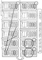
図21は、ストレージ装置をそなえるストレージシステム100におけるディスク故障からの復旧の手法の一例を示す図である。図21に示すストレージシステム100は、6つのHDD−1〜HDD−6に3つのストライプ−1〜ストライプ−3が設定されたディスクグループをそなえ、このディスクグループでは消失訂正符号(Erasure Code)により符号化された情報が各ストライプに格納される。
FIG. 21 is a diagram illustrating an example of a recovery method from a disk failure in the
例えば図21の上段に示すように、ストライプ−2には、データが4つのHDD−2〜HDD−5に分散して格納され(2D1〜2D4参照)、ストライプ−2のパリティがHDD−6に格納される(2P参照)。ここで、ストライプ−2におけるHDD−1は空きブロックであり、HDD−2〜HDD−6のいずれかの故障時に代替ブロックとして用いられる。また、2D1とはストライプ−“2”のデータ“D”のうちの“1”番目のブロックを意味し、2Pとはストライプ−“2”のパリティ“P”のブロックを意味する。なお、以下の説明において、代替ブロックの“空き”の表記を省略する場合がある。 For example, as shown in the upper part of FIG. 21, in stripe-2, data is distributed and stored in four HDD-2 to HDD-5 (see 2D1 to 2D4), and the parity of stripe-2 is stored in HDD-6. Stored (see 2P). Here, HDD-1 in stripe-2 is an empty block, and is used as an alternative block when any of HDD-2 to HDD-6 fails. Further, 2D1 means the “1” th block of the data “D” of the stripe “2”, and 2P means a block of the parity “P” of the stripe “2”. In the following description, the description of “empty” in the alternative block may be omitted.
このようなストレージシステム100においてHDD−5が故障した場合、図21の下段に例示するように、ストレージ装置のコントローラモジュール(CM;Controller Module,図示省略)等の制御装置(以下、CMと表記する)は、HDD−5に格納されていたデータを復旧するために再構築(リビルド)を行なう。例えばCMは、ストライプ−1について、HDD−1〜HDD−4から1D1〜1D4のデータを取得し、1D1〜1D4からパリティ計算を行なって1Pを生成し、生成した1PをHDD−6の代替ブロックに書き込む。他のストライプについても同様に、CMは、ストライプ−2について2D1〜2D3及び2Pのデータから2D4を生成し、生成した2D4をHDD−1の代替ブロックに書き込む。また、CMは、ストライプ−3について3D1、3D2、3D4、及び3Pのデータから3D3を生成し、生成した3D3をHDD−2の代替ブロックに書き込む。
When the HDD-5 fails in such a
関連する技術として、データの各ブロックを消失符号化して、グループ化されたストレージノードに分配し、ストレージノードに障害が発生した場合、未使用のノードに他のノードのデータを使用して故障ノードのデータの再構築を行なう技術が知られている(例えば、特許文献1参照)。 As a related technology, each block of data is erasure-coded and distributed to the grouped storage nodes. When a failure occurs in the storage node, the data of the other node is used for the unused node. A technique for reconstructing the data is known (see, for example, Patent Document 1).
ストレージシステム100において、各HDD上のブロック配置はCM等による当該HDDの空き領域の管理に応じて変化する。
In the
従って、図22の下段に例示するように、ストライプ単位のデータ解放や再割り当てが繰り返されると、各HDD内のブロックには、データ又はパリティの情報がストライプ順ではなくランダムな順序で格納されることになる。例えばHDD−3には、HDDの記憶領域の先頭から順に、2D2(ストライプ−2)、1D3(ストライプ−1)、3D1(ストライプ−3)のブロックが格納される。 Therefore, as illustrated in the lower part of FIG. 22, when data release or reassignment in units of stripes is repeated, data or parity information is stored in a random order instead of the stripe order in the blocks in each HDD. It will be. For example, the HDD-3 stores 2D2 (stripe-2), 1D3 (stripe-1), and 3D1 (stripe-3) blocks in order from the top of the storage area of the HDD.
このような図22の下段に示す状態においてHDD−5が故障した場合を考える。この場合、各HDDでは、ストライプ−1〜ストライプ−3の構成ブロックの配置がランダムとなっているため、図23の下段に例示するように、CMによるリビルドの際、HDD上のアドレス順とは異なる順序によるHDDへのアクセスが発生する。 Consider a case where the HDD-5 fails in such a state shown in the lower part of FIG. In this case, since the arrangement of the constituent blocks of stripe-1 to stripe-3 is random in each HDD, as illustrated in the lower part of FIG. Access to the HDD in a different order occurs.
例えばHDD−3では、CMにより、最初にストライプ−1のリカバリのために記憶領域の中央付近のアドレスから1D3が読み出され、次いでストライプ−2のリカバリのために記憶領域の先頭付近のアドレスから2D2が読み出される。そして、最後にストライプ−3のリカバリのために記憶領域の末尾(最終アドレス)付近のアドレスから3D1が読み出される。 For example, in HDD-3, 1D3 is first read from the address near the center of the storage area for recovery of stripe-1 by CM, and then from the address near the beginning of the storage area for recovery of stripe-2. 2D2 is read. Finally, 3D1 is read from an address near the end (final address) of the storage area for recovery of stripe-3.
また、例えば代替ブロックを持つHDD−1では、CMにより、最初にストライプ−1のリカバリのために記憶領域の末尾付近のアドレスから1D1が読み出され、次いでストライプ−2のリカバリのために他のHDDの情報に基づき生成された2D4が記憶領域の中央付近のアドレスに書き込まれる。そして、最後にストライプ−3のリカバリのために記憶領域の先頭付近のアドレスから3Pが読み出される。 For example, in HDD-1 having a replacement block, 1D1 is first read from the address near the end of the storage area for recovery of stripe-1 by CM, and then for recovery of stripe-2. 2D4 generated based on the HDD information is written at an address near the center of the storage area. Finally, 3P is read from the address near the beginning of the storage area for the recovery of stripe-3.
このように、ストレージシステム100においてストライプ単位のデータ解放や再割り当てが繰り返されると、各HDDでは、リビルドの際にリカバリ対象のストライプの順にアクセスが行なわれるため、このアクセスはランダムアクセスとなる。
As described above, when data release and reassignment in units of stripes are repeated in the
図23の例では、ストレージシステム100が3つのストライプを管理し、各HDDに最大3つのブロックが格納されるものとして説明したが、実際にはさらに多くのストライプが管理され、1つのHDDに格納されるブロックも非常に多くなる。例えばHDDが100MB/s程度の読み出し性能を持つSAS(Serial Attached SCSI(Small Computer System Interface))規格に対応した記憶装置であり、ブロックが4KB程度の小さいサイズである場合、図23に示す例では各HDDのアクセスが10MB/s程度のランダムアクセスとなってしまう。
In the example of FIG. 23, it has been described that the
以上のように、ストレージ装置を1以上そなえるストレージシステムでは、HDDに格納されたブロックがストライプ順ではない場合、リビルドの際にストレージ装置においてHDDの読み出しがランダム化され、性能劣化が生じてしまう。 As described above, in a storage system having one or more storage devices, when the blocks stored in the HDD are not in the stripe order, the reading of the HDD is randomized in the storage device at the time of rebuilding, resulting in performance degradation.
なお、上述した課題は、上述の如く、消失訂正符号により符号化された情報を格納するストレージシステムにおいて生じ得るものである。このようなストレージシステムとしては、RAID(Redundant Arrays of Inexpensive Disks)5と、RAID5に対してストライプを追加のディスクにまで拡張するワイドストライプとを組み合わせた構成が挙げられる。また、RAID5に代えて他のRAID技術(例えばRAID6)或いは複数のRAID技術の組み合わせが採用された構成や、他の消失訂正符号を用いたストレージシステムにおいても、上記課題は同様に生じ得る。
Note that the above-described problem can occur in a storage system that stores information encoded by an erasure correction code as described above. An example of such a storage system is a combination of RAID (Redundant Arrays of Inexpensive Disks) 5 and a wide stripe that extends a stripe to
さらに、代替ブロックを持たない、例えば通常のRAID5やRAID6等を採用したストレージシステムにおいても、HDDに格納されたブロックがストライプ順にならない場合、上記課題は同様に生じ得る。
Furthermore, even in a storage system that does not have an alternative block, for example, a
1つの側面では、本発明は、複数の記憶装置をそなえるストレージシステムにおいて、故障した記憶装置のデータの復旧処理における他の記憶装置からの情報の読み出し性能を向上させることを目的とする。 In one aspect, an object of the present invention is to improve the performance of reading information from another storage device in a data recovery process of a failed storage device in a storage system having a plurality of storage devices.
1つの態様では、本件のストレージ装置は、1以上の第1記憶装置と、前記1以上の第1記憶装置が記憶する複数の第1ブロック情報を、前記1以上の第1記憶装置から記憶領域のアドレス順に読み出す読出部と、をそなえる。前記第1ブロック情報は、故障した第2記憶装置が記憶する複数の第2ブロック情報の復元に用いられる情報である。また、前記ストレージ装置は、前記読出部により前記1以上の第1記憶装置から読み出し済の第1ブロック情報を、前記複数の第2ブロック情報を段階的に復元するために、前記複数の第2ブロック情報の復元先へ出力する出力部をさらにそなえる。 In one aspect, the storage device of the present application stores one or more first storage devices and a plurality of first block information stored in the one or more first storage devices from the one or more first storage devices. And a reading section for reading out in order of addresses. The first block information is information used for restoring a plurality of second block information stored in the failed second storage device. In addition, the storage device restores the first block information read from the one or more first storage devices by the reading unit, and the plurality of second blocks in order to restore the plurality of second block information in stages. An output unit for outputting the block information to the restoration destination is further provided.
1つの側面では、複数の記憶装置をそなえるストレージシステムにおいて、故障した記憶装置のデータの復旧処理における他の記憶装置からの情報の読み出し性能を向上させることができる。 In one aspect, in a storage system having a plurality of storage devices, it is possible to improve the performance of reading information from other storage devices in the data recovery process of the failed storage device.
以下、図面を参照して本発明の実施の形態を説明する。ただし、以下に説明する実施形態は、あくまでも例示であり、以下に明示しない種々の変形や技術の適用を排除する意図はない。すなわち、本実施形態を、その趣旨を逸脱しない範囲で種々変形して実施することができる。なお、以下の実施形態で用いる図面において、同一符号を付した部分は、特に断らない限り、同一若しくは同様の部分を表す。 Embodiments of the present invention will be described below with reference to the drawings. However, the embodiment described below is merely an example, and there is no intention to exclude various modifications and technical applications that are not explicitly described below. That is, the present embodiment can be implemented with various modifications without departing from the spirit of the present embodiment. Note that, in the drawings used in the following embodiments, portions denoted by the same reference numerals represent the same or similar portions unless otherwise specified.
〔1〕第1実施形態
〔1−1〕ストレージシステムの構成例
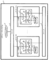
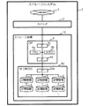
図1は第1実施形態の一例としてのストレージシステム1の構成例を示す図である。図1に示すように、ストレージシステム1は例示的にスイッチ2及び6、並びに1以上(図1では複数)のストレージ装置10−1〜10−m(mは自然数)をそなえることができる。なお、以下の説明においてストレージ装置10−1〜10−mを区別しない場合には単にストレージ装置10と表記する。
[1] First Embodiment [1-1] Configuration Example of Storage System FIG. 1 is a diagram illustrating a configuration example of a
ストレージシステム1は、ユーザに対してストレージ装置10の記憶領域を提供するものであり、例えばネットワーク3を介してユーザの使用するユーザ端末(ホスト装置)からストレージ装置10へのアクセスが可能となっている。ストレージシステム1としては、例えば複数のストレージ装置10(筐体)をそなえるクラスタ構成のストレージシステムであってもよいし、単一のストレージ装置10をそなえた構成であってもよい。図1の例では、ストレージシステム1は、m個のストレージ装置10をそなえ、分散アルゴリズムによりストレージ装置10が相互に通信可能な分散ストレージシステムである。
The
スイッチ2は、ストレージ装置10及びネットワーク3と接続され、ストレージシステム1を使用するユーザのユーザ端末とストレージ装置10との間の通信(クライアント通信)の切り替え制御等を行なうものである。スイッチ6は、ストレージ装置10と接続され、ストレージ装置10間の通信(クラスタ内部通信)の切り替え制御等を行なうものである。
The
なお、ネットワーク3は、インターネットであってもよいし、LAN(Local Area Network)又はSAN(Storage Area Network)等のイントラネットを形成するネットワークであってもよい。また、図1の例ではストレージシステム1にスイッチ2及び6がそれぞれ1つずつそなえられるものとしたが、これに限定されるものではない。例えば複数のストレージ装置10が互いに異なる拠点にそなえられる場合には、各拠点にスイッチ2及びスイッチ6を設け、スイッチ2間及びスイッチ6間を、それぞれインターネットやLAN又はSAN等のイントラネットを形成するネットワーク等を介して相互に通信可能に接続してもよい。さらに、ストレージシステム1は、スイッチ2及びスイッチ6をクライアント通信及びクラスタ内部通信で共用のスイッチとして、いずれか一方のみそなえてもよい。
The
ストレージ装置10は、それぞれ1以上(図1では1つ)のCM4をそなえる。また、ストレージ装置10−1は記憶装置5−1をそなえ、ストレージ装置10−mは記憶装置5−nをそなえる。なお、以下の説明において記憶装置5−1〜5−nを区別しない場合には単に記憶装置5と表記する。ストレージ装置10は、図1の例ではそれぞれ1つの記憶装置5をそなえるものとしたが、複数の記憶装置5をそなえてもよい。
Each
CM4は、スイッチ2を介したユーザ端末からの要求、並びにスイッチ6を介した他のストレージ装置10(CM4)からの要求に応じて、記憶装置5の記憶領域に対する種々のアクセス制御を行なうコンピュータ(情報処理装置)の一例である。このアクセス制御には、記憶装置5の故障に伴うリビルド処理が含まれる。例えばCM4は、リビルド処理において、他のストレージ装置10のCM4とともに、分散アルゴリズムに基づく協調動作を行なうことができる。
The
CM4は、例えばCPU(Central Processing Unit)4a、メモリ4b、及びIF(Interface)4c〜4eをそなえる。
The
CPU4aは、種々の制御や演算を行なう演算処理装置(プロセッサ)の一例である。CPU4aは、メモリ4b、及びIF4c〜4eとバスで相互に通信可能に接続され、メモリ4b又は図示しないROM(Read Only Memory)等に格納されたプログラムを実行することにより、CM4における種々の機能を実現することができる。
The
メモリ4bは、種々のデータやプログラムを格納する記憶装置である。第1実施形態に係るメモリ4bはさらに、後述するリビルド処理において記憶装置5から読み出した情報及び記憶装置5へ格納する(書き込む)情報を一時的に記憶するキャッシュメモリとして用いられる。なお、メモリ4bとしては、例えばRAM(Random Access Memory)等の揮発性メモリが挙げられる。
The
IF4c〜4eは、それぞれスイッチ2、記憶装置5、スイッチ6との間の接続及び通信の制御等を行なう通信インタフェースである。例えばIF4c及び4eはホストアダプタであり、IF4dはデバイス(ディスク)アダプタである。これらの通信インタフェース(アダプタ)としては、LAN、SAN、FC(Fibre Channel)、インフィニバンド(InfiniBand)等に準拠したアダプタが挙げられる。
The
記憶装置5は、種々のデータやプログラム等を格納するハードウェアである。記憶装置5としては、例えばHDD等の磁気ディスク装置や、SSD等の半導体ドライブ装置等の各種記憶装置が挙げられる。
The
〔1−2〕ストレージシステムにおけるリビルド処理について
次に、第1実施形態に係るストレージシステム1におけるリビルド処理について、図2及び図3を参照して簡単に説明する。以下、前提として、記憶装置5がHDDであるものとする。また、ストレージシステム1が6つのHDD−1〜HDD−6に3つのストライプ−1〜ストライプ−3が設定されたディスクグループをそなえ、このディスクグループでは消失訂正符号により符号化された情報が各ストライプに格納されるものとする(図23の上段参照)。
[1-2] Rebuild Process in Storage System Next, the rebuild process in the
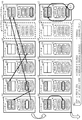
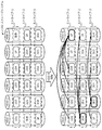
例えば図23の上段に示す状態からHDD−5が故障した場合に、ストライプ−2の消失したブロック(消失ブロック)である2D4をHDD−1に復旧する場合を想定する。ストレージシステム1(ストレージ装置10のCM4)は、図2の上段に示すように、ストライプ順に関係なく、各HDD上で物理アドレス順にシーケンシャルにブロックを読み出す。例えばHDD−3では、2D2、1D3、3D1の順にブロックが読み出される。なお、HDD−2ではHDD−5の消失ブロック(3D3)の復旧及び格納前であるため、1D2、2D1の順にブロックが読み出される。
For example, when HDD-5 fails from the state shown in the upper part of FIG. 23, it is assumed that 2D4, which is a lost block (lost block) of stripe-2, is restored to HDD-1. As shown in the upper part of FIG. 2, the storage system 1 (
そして、ストレージシステム1(CM4)は、図2の中段に示すように、読み出したブロック(データ(D)ブロック及びパリティ(P)ブロック)順に、インクリメンタルに各ストライプを復旧する。以下、データブロック及びパリティブロックを区別しない場合には、これらを情報ブロックと表記する。 The storage system 1 (CM4) then restores each stripe incrementally in the order of the read blocks (data (D) block and parity (P) block), as shown in the middle part of FIG. Hereinafter, when a data block and a parity block are not distinguished, they are referred to as an information block.
例えばHDD−3の記憶領域の先頭付近のアドレスに格納された2D2が最初に読み出されると、この2D2がHDD−1の新2D4のブロックに反映される(矢印(1)参照)。次いで、HDD−6の記憶領域の中央付近のアドレスに格納された2Pが読み出されると、この2PがHDD−1の新2D4のブロックに反映される(矢印(2)参照)。次に、HDD−2の記憶領域の中央付近のアドレスに格納された2D1が読み出されると、この2D1がHDD−1の新2D4のブロックに反映される(矢印(3)参照)。そして、HDD−4の記憶領域の中央付近のアドレスに格納された2D3が読み出されると、この2D3がHDD−1の新2D4のブロックに反映される(矢印(4)参照)。 For example, when 2D2 stored at an address near the beginning of the storage area of HDD-3 is first read, this 2D2 is reflected in the new 2D4 block of HDD-1 (see arrow (1)). Next, when 2P stored at an address near the center of the storage area of HDD-6 is read, this 2P is reflected in the new 2D4 block of HDD-1 (see arrow (2)). Next, when 2D1 stored at an address near the center of the storage area of HDD-2 is read, this 2D1 is reflected in the new 2D4 block of HDD-1 (see arrow (3)). When 2D3 stored at an address near the center of the storage area of HDD-4 is read, this 2D3 is reflected in the new 2D4 block of HDD-1 (see arrow (4)).
なお、図2にはストライプ−2の消失ブロックに着目して新2D4の復旧について説明したが、ストライプ−1及びストライプ−3の消失ブロックについて新1P及び新3D3を復旧する処理も、各HDDからのシーケンシャルな情報ブロックの読み出しの過程で順次実施される。 In FIG. 2, the recovery of the new 2D4 has been described focusing on the lost block of the stripe-2, but the process of recovering the new 1P and the new 3D3 for the lost block of the stripe-1 and the stripe-3 is also performed from each HDD. The sequential information blocks are sequentially read in the process of reading.
以上のように、第1実施形態に係るストレージシステム1は、読み出したブロックを用いて段階的に消失ブロックを復旧することができる。これにより、ストレージシステム1では、記憶装置の故障によるリビルド処理において、CM4は各記憶装置からシーケンシャルに情報ブロックを読み出すことができるため、正常な記憶装置からの情報の読み出し性能を向上することができる。従って、図23に示す各記憶装置からの完全なランダムアクセスにより情報を読み出す手法と比較して、最大で10倍以上のスループットとすることができ、リカバリ性能を大幅に向上させることができる。
As described above, the
ここで、ストレージシステム1が段階的にストライプを復旧することのできる理由を説明する。
Here, the reason why the
ストレージシステム1では、各ストライプの情報ブロックが消失訂正符号により符号化されている。消失訂正符号により符号化された情報ブロックでは、消失ブロックの情報を、或るストライプにおける消失ブロック以外の正常な情報ブロックから算出(復旧)することができる。この算出手法としては、パリティが1つの場合、例えば正常な情報ブロックの排他的論理和(XOR)を算出するといった手法が挙げられる。
In the
XOR演算は、可換(Commutative)演算である。このため、ストレージシステム1は、各HDDからシーケンシャルに読み出した情報ブロックを用いて段階的に(インクリメンタルに)各ストライプを復旧することができるのである。以下の説明では、XOR演算を示す演算子として“+”を用い、図面では演算子として“+”を丸で囲んだ記号を用いる。
The XOR operation is a commutative operation. For this reason, the
例えば図2の下段に示すように、対比例としての図23の演算では、消失ブロックを復旧するための全ての情報ブロックが揃ってから、新2D4=2D1+2D2+2D3+2Pの演算が順序通りに行なわれる。一方、第1実施形態に係るストレージシステム1は、図2の矢印(1)及び(2)で読み出した2D2及び2Pの演算を行ない、その演算結果と図2の矢印(3)で読み出した2D1との演算を行なう。そして、ストレージシステム1は、最後にその演算結果と図2の矢印(4)で読み出した2D3との演算を行なう。
For example, as shown in the lower part of FIG. 2, in the operation of FIG. 23 as a comparative example, the new 2D4 = 2D1 + 2D2 + 2D3 + 2P operation is performed in order after all the information blocks for recovering the lost block are prepared. On the other hand, the
なお、消失ブロックの情報を算出(復旧)する算出手法としては、上述したXOR演算に限定されるものではない。例えばストライプごとにパリティが2つ以上含まれる場合には、XOR演算を用いたリードソロモン(RS;Reed-Solomon)符号ベースの演算が行なわれてもよい。ストレージシステム1では、このようなRS符号を消失訂正符号として用いて符号化された情報が各ストライプに格納されている場合でも、段階的に消失ブロック(ストライプ)を復旧することができる。消失ブロックの情報を算出(復旧)する算出手法としては、消失訂正符号がガロア体(有限体)を用いる可換演算の可能な符号であれば、上述したもの以外の種々の手法が用いられてよい。
Note that the calculation method for calculating (restoring) the information of the lost block is not limited to the XOR operation described above. For example, when two or more parities are included in each stripe, a Reed-Solomon (RS) code-based operation using an XOR operation may be performed. In the
説明の簡略化のため、以下の説明では、消失ブロックの情報の算出手法としてXOR演算が用いられるものとする。 In order to simplify the explanation, in the following explanation, it is assumed that an XOR operation is used as a method for calculating information of the lost block.
ところで、CM4は、各記憶装置5から情報ブロックを読み出す都度、当該情報ブロックのストライプにおける復旧先の代替ブロック(リカバリ対象ブロック)へXOR演算等による反映を行なってよい。しかし、当該代替ブロックを有する記憶装置5においてもシーケンシャルリードが行なわれているため、当該代替ブロックを有する記憶装置5では、シーケンシャルリードの最中に代替ブロックへの書き込みアクセスが頻発して読み出し性能が劣化し、リビルド処理の性能低下が生じることがある。
By the way, each time the information block is read from each
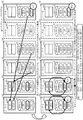
そこで、CM4(又は記憶装置5)は、図3に示すように、或るストライプの消失ブロックを復旧する場合、当該消失ブロックの復旧に用いる情報ブロックをキャッシュメモリ等に一時的に保持しておくことができる。 Therefore, as shown in FIG. 3, the CM 4 (or the storage device 5) temporarily stores an information block used for recovery of the lost block in a cache memory or the like when recovering the lost block of a certain stripe. be able to.
例えばCM4は、図3の矢印(1)に示すように、HDD−3から2D2を読み出し、HDD−1の新2D4のための書込キャッシュに反映する。このときストライプ−2の2D4復旧の進捗は、2D4として2D2が設定された状態である。
For example, the
また、CM4は、図3の矢印(2)に示すように、HDD−6から2Pを読み出し、書込キャッシュに反映する。このときストライプ−2の2D4復旧の進捗は、2D4として、2D4に設定された2D2と2PとのXOR演算結果が設定された状態である。
Further, the
なお、このタイミングで書込キャッシュの容量が逼迫した場合、CM4は、書込キャッシュ内の情報ブロック(2D2+2P)をHDD−1の代替ブロックに書き込む(フラッシュする)。
When the capacity of the write cache becomes tight at this timing, the
さらに、CM4は、図3の矢印(3)に示すように、HDD−2から2D1を読み出し、HDD−1の代替ブロック(新2D4)の情報を書込キャッシュにリロードする。そして、CM4は、2D1を書込キャッシュに反映する。このときストライプ−2の2D4復旧の進捗は、2D4として、書込キャッシュにリロードされた2D2+2Pと2D1とのXOR演算結果が設定された状態である。
Further, the
また、CM4は、図3の矢印(4)に示すように、HDD−4から2D3を読み出し、書込キャッシュに反映する。このときストライプ−2の2D4復旧の進捗は、2D4として、2D4に設定された(2D2+2P)+2D1と2D3とのXOR演算結果が設定された状態である。
Further, the
なお、このタイミングで書込キャッシュの容量が逼迫した場合、CM4は、書込キャッシュ内の情報ブロック((2D2+2P)+2D1)+2D3をHDD−1の代替ブロックに書き込む(フラッシュする)。
When the capacity of the write cache becomes tight at this timing, the
以上により書込キャッシュを用いた段階的なリビルド処理が行なわれる。なお、ストライプ−1及びストライプ−3の消失ブロックについて新1P及び新3D3を復旧する処理も、HDD−2及びHDD−6に対応する書込キャッシュにおいて、各HDDからのシーケンシャルな情報ブロックの読み出しの過程で順次実施される。 As described above, the step-by-step rebuild process using the write cache is performed. The process of restoring the new 1P and new 3D3 for the lost blocks of stripe-1 and stripe-3 is also performed by reading sequential information blocks from each HDD in the write cache corresponding to HDD-2 and HDD-6. Sequentially implemented in the process.
各記憶装置5についてシーケンシャルに情報ブロックを読み込む場合、できるだけ多くの情報ブロックを保持できるように、大容量のキャッシュメモリが用いられることが好ましい。しかし、CM4(又は記憶装置5)の各々に大容量のキャッシュメモリを搭載することは、コスト増加の観点から難しい場合がある。
When information blocks are sequentially read from each
これに対し、上述したストレージシステム1によれば、図3に示すように、書込キャッシュの容量が逼迫した等の場合に、書込キャッシュに保持された情報ブロックをまとめてXOR演算して代替ブロックに書き込むことができる。そして、CM4は、容量の空いた書込キャッシュに情報ブロックを蓄積していき、再び書込キャッシュの容量が逼迫した等の場合に、代替ブロックから情報を再読み出しし、書込キャッシュに格納された情報ブロックと再読み出しした情報とをXOR演算して代替ブロックに書き込むのである。
On the other hand, according to the
このように、ストレージシステム1では、図2に示すように各ストライプをインクリメンタルに復旧することができるため、消失ブロックの復旧データである全ての情報ブロックが揃うまで書込キャッシュに情報ブロックを溜め込まなくてよい。これにより、ストレージシステム1は、大容量のキャッシュメモリをそなえなくてもよく、コスト増加を抑制することができる。
Thus, in the
〔1−3〕ストレージ装置の構成例
次に、図4を参照してストレージ装置10の構成例について説明する。ストレージ装置10(CM4)は、複数のストレージ装置10のCM4と協働して、複数の記憶装置5に対する各種制御を行なうことができる。この制御には、ユーザ端末からの書込要求に応じて書込データのパリティ演算を行ない、複数の情報ブロックを生成してストライプとして各記憶装置5に分散させる制御が含まれる。また、この制御には、ユーザ端末からの読出要求に応じてストライプから情報ブロックを取得して読出データを構築し、ユーザ端末へ出力する制御も含まれる。
[1-3] Configuration Example of Storage Device Next, a configuration example of the
また、例えばCM4は、ユーザ端末からの要求に応じてアクセス対象のストライプに対応する記憶装置5の情報ブロックへのアクセスを行なったり、記憶装置5の故障を検出した場合に他のストレージ装置10のCM4へ通知を行なってリビルド処理を実行することができる。これらの制御は、既知の種々の手法により行なうことが可能であり、その詳細な説明は省略する。
Further, for example, the
さらに、第1実施形態に係るストレージ装置10(CM4)は、リビルド処理において図2及び図3に示すような動作を実現するため、図4に示すように、例示的に通信部41、読出部42、キャッシュメモリ43、及び書込部44をそなえることができる。
Furthermore, since the storage apparatus 10 (CM4) according to the first embodiment realizes the operations shown in FIGS. 2 and 3 in the rebuild process, as shown in FIG. 42, a
通信部41は、他のCM4との間で通信を行なうものであり、例えばリビルド処理に関する制御情報や情報ブロック等の種々の情報を他のCM4との間で送受信する。例えば通信部41は、図1に示すCPU4a、IF4c、及びIF4eの少なくとも一部の機能により実現することができる。
The
例えば記憶装置5(第2記憶装置)の故障を検出したCM4は、故障した記憶装置5に格納されていた消失ブロック(第2ブロック情報)に関する情報を通信部41により他のCM4に通知する。この通知を受信したCM4は、自装置10がそなえる記憶装置5について、消失ブロックを復旧させる代替ブロックの有無や、消失ブロックと同じストライプの情報ブロックの有無等を判断して、消失ブロックのストライプごとに復旧先の記憶装置5を決定する。例えば記憶装置5に代替ブロックが有り、或る消失ブロックと同じストライプの情報ブロックが無い場合、CM4は、自装置10の記憶装置5が当該消失ブロックのストライプの復旧先であることを通信部41により他のCM4に通知する。
For example, the
読出部42は、リビルド処理において、自装置10がそなえる記憶装置5(第1記憶装置)に格納された情報ブロック(第1ブロック情報)を記憶装置5の物理アドレスの先頭からシーケンシャルに読み出し、読み出した情報ブロックを順次通信部41に渡す。なお、自装置10が或るストライプの復旧先(復元先)の記憶装置5をそなえる場合、読出部42は、シーケンシャルに読み出す過程で当該情報ブロックの読み出しをスキップしてよい。
In the rebuild process, the
このように、読出部42は、1以上の第1記憶装置5が記憶する複数の第1ブロック情報であって、故障した第2記憶装置5が記憶する複数の第2ブロック情報の復元に用いられる複数の第1ブロック情報を、1以上の第1記憶装置5から記憶領域のアドレス順に読み出すものであるといえる。
As described above, the
なお、通信部41は、読出部42が読み出した情報ブロックを、当該情報ブロックのストライプの復旧先であるストレージ装置10(CM4)へ送信(転送)し、復旧先のCM4は、他のCM4から受信した情報ブロックを書込部44に出力する。このとき復旧先のCM4は、書込部44によりキャッシュメモリ43の使用量を監視し、容量が逼迫した場合、通信部41により他のCM4に対して容量が逼迫したことを示す通知(或いは情報ブロックの送信を抑止させる通知)を行なうことができる。この通知を受信したCM4(通信部41)は、読出部42に対して復旧先のCM4に対応する情報ブロックの読み出しを中止させてもよいし、読出部42に読み出された当該情報ブロックをキャッシュメモリ43に一時的に格納(退避)してもよい(図4の破線参照)。
Note that the
また、復旧先のCM4は、キャッシュメモリ43が使用可能になった場合、通信部41により他のCM4に対して容量が確保できたことを示す通知(或いは情報ブロックの送信を再開させる通知)を行なうことができる。この通知を受信したCM4(通信部41)は、読出部42に対して復旧先のCM4に対応する情報ブロックを読み出させてもよいし、キャッシュメモリ43に格納した当該情報ブロックを復旧先のCM4へ送信してもよい(図4の破線参照)。
Further, when the
このように、通信部41は、読出部42により1以上の第1記憶装置5から読み出し済の第1ブロック情報を、複数の第2ブロック情報を段階的に復元するために、複数の第2ブロック情報の復元先へ出力する出力部の一例であるといえる。
In this way, the
キャッシュメモリ43は、図3に示す書込キャッシュの一例であり、例えば図1に示すメモリ4bの少なくとも一部の記憶領域を用いることにより実現することができる。キャッシュメモリ43は、自装置10が復旧先である場合に、復旧に用いる情報ブロックが格納される記憶領域である。また、上述のように、読出部42が読み出した情報ブロックを復旧先のCM4へ送信できない場合、当該情報ブロックの退避用の記憶領域として用いられてもよい。
The
このように、キャッシュメモリ43は、他の第1ストレージ装置10から入力される第1ブロック情報を保持する保持部の一例であるといえる。
Thus, it can be said that the
書込部44は、通信部41から入力された情報ブロックをキャッシュメモリ43へ書き込む。また、書込部44は、例えば定期的に、キャッシュメモリ43の使用量を監視し、使用量が閾値を超えた(容量が逼迫した)場合、その旨を通信部41へ通知する。このとき書込部44は、記憶装置5の代替ブロックに情報ブロックが格納されているか否かを判断する。なお、閾値は、情報ブロックのサイズやキャッシュメモリ43の容量に応じて予め設定されるものであり、閾値として例えばキャッシュメモリ43の記憶領域のサイズの80%〜90%等の値を設定することができる。
The
代替ブロックに情報ブロックが格納されていない場合、書込部44は、キャッシュメモリ43に格納された複数の情報ブロックについてXOR演算を行ない、演算結果を記憶装置5の代替ブロック(空き記憶領域)に書き込み、キャッシュメモリ43をクリアする。一方、代替ブロックに情報ブロックが格納されている場合、書込部44は、代替ブロックから情報ブロックを読み出し、読み出した情報ブロックと、キャッシュメモリ43に格納された複数の情報ブロックと、についてXOR演算を行ない、演算結果を記憶装置5の代替ブロックに書き込み、キャッシュメモリ43をクリアする。なお、書込部44は、キャッシュメモリ43の使用量が閾値以下となった(使用可能になった)場合、その旨を通信部41へ通知する。
When the information block is not stored in the alternative block, the
なお、書込部44によるキャッシュメモリ43の容量の監視において、使用量が閾値を超えたか否かを判断する代わりに、キャッシュメモリ43の残容量を監視し、残容量が閾値以下となったか否かを判断してもよい。或いは、情報ブロックが一定(ブロック単位の)サイズであるため、書込部44は、キャッシュメモリ43に格納した情報ブロックの数をカウントし、情報ブロックの数が所定数以上となった場合にキャッシュメモリ43の容量が逼迫したと判断してもよい。
In the monitoring of the capacity of the
また、書込部44は、例えば受信した(又はキャッシュメモリ43に格納した)情報ブロックの数をカウントし、カウント値が閾値に達した場合に、当該ストライプの復旧(リカバリ)処理が完了したと判断することができる。なお、カウントする数としては、これに限定されるものではなく、代替ブロックに反映した情報ブロックの数であってもよいし、XOR演算を行なった回数であってもよい。また、情報ブロックの数をカウントする場合、閾値を「ストライプに含まれる情報ブロックの数」−「当該ストライプに含まれる消失ブロックの数」とすることができる。或いは、XOR演算を行なった回数をカウントする場合、閾値を「ストライプに含まれる情報ブロックの数」−「当該ストライプに含まれる消失ブロックの数」−1としてもよい。
The
このように、書込部44は、他の第1ストレージ装置10から入力された第1ブロック情報に基づき、第2ブロック情報を段階的に復元する復元部の一例であるといえる。この復元部の一例としての書込部44は、入力された第1ブロック情報及び第2ブロック情報の復元先が記憶する情報を用いて、消失訂正符号に基づく演算を行ない、演算結果を第2ブロック情報の復元先へ書き込むのである。また、この復元部の一例としての書込部44は、所定のタイミングで、キャッシュメモリ43が保持する1以上の第1ブロック情報に基づき、第2ブロック情報を段階的に復元するのである。
Thus, it can be said that the
〔1−4〕ストレージシステムにおけるリビルド処理の動作説明
次に、図5〜図10を参照して、ストレージシステム1におけるリビルド処理の動作をストレージ装置10間の通信に着目して説明する。以下、ストレージシステム1が6台のストレージ装置10をそなえるものとし、便宜上、これらのストレージ装置10をノード−1〜ノード−6と表記する。また、ノード−5が故障し、ストレージシステム1がノード5のHDD−5に格納された2D4、1P、3D3の3ブロックのリビルド処理を行なうものとする。
[1-4] Description of Rebuild Process Operation in Storage System Next, the rebuild process operation in the
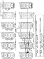
図5の上段に示すように、各ノードのCM4は、HDDの先頭ブロックを読出部42により読み出し、読み出した先頭ブロック(情報ブロック)を通信部41により復旧先の代替ブロック(リカバリ対象ブロック)を有するノードへ転送する。情報ブロックを受信したノードは、キャッシュメモリ43に格納する。
As shown in the upper part of FIG. 5, the
図5の例では、ノード−1が2D4(ストライプ−2)のリカバリ対象ブロックを有し、ノード−2が3D3(ストライプ−3)のリカバリ対象ブロックを有し、ノード−6が1P(ストライプ−1)のリカバリ対象ブロックを有している。この場合、ノード−2及びノード−4は、それぞれHDD−2の先頭ブロックの1D2及びHDD−4の先頭ブロックの1D4をノード−6に転送し、ノード−3は、HDD−3の先頭ブロックの2D2をノード−1に転送する。また、ノード−1及びノード−6は、それぞれHDD−1の先頭ブロックの3P及びHDD−6の先頭ブロックの3D4をノード−2に転送する。 In the example of FIG. 5, node-1 has a recovery target block of 2D4 (stripe-2), node-2 has a recovery target block of 3D3 (stripe-3), and node-6 has 1P (stripe- 1) the recovery target block. In this case, the node-2 and the node-4 transfer 1D2 of the first block of the HDD-2 and 1D4 of the first block of the HDD-4 to the node-6, respectively, and the node-3 transmits the first block of the HDD-3. Transfer 2D2 to node-1. In addition, the node-1 and the node-6 transfer 3P4 of the first block of the HDD-1 and 3D4 of the first block of the HDD-6 to the node-2, respectively.
次いで、図5の下段に示すように、ノード−2及びノード−6のCM4は、書込部44により、キャッシュメモリ43の容量が枯渇したと判断して、ノード−2及びノード−6のそれぞれのリカバリ対象ブロックについて部分的なリカバリを実施する。このときノード−2及びノード−6のリカバリ対象ブロックに書き込まれる情報である3D3’及び1P’は、それぞれ3D3’=3P+3D4、1P’=1D2+1D4となる。一例として、図6に示すように、ストライプ番号とインデックス番号(パリティを除く)をそれぞれバイナリ化して、3P=000100、3D4=011100、1D2=001010、1D4=001100とした場合、3D3’及び1P’はそれぞれ以下の値となる。
Next, as shown in the lower part of FIG. 5, the
3D3’=3P +3D4=000100+011100=011000
1P’ =1D2+1D4=001010+001100=000110
3D3 ′ = 3P + 3D4 = 000100 + 011100 = 011000
1P ′ = 1D2 + 1D4 = 001010 + 001100 = 000110
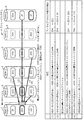
次に、図7の上段に示すように、各ノードのCM4は、HDDの2ブロック目(2ブロック目がリカバリ対象ブロックであれば3ブロック目)を読出部42により読み出し、読み出した情報ブロックを通信部41によりリカバリ対象ブロックを有するノードへ転送する。情報ブロックを受信したノードは、キャッシュメモリ43に格納する。
Next, as shown in the upper part of FIG. 7, the
図7の例では、ノード−1及びノード−3は、それぞれHDD−1の3ブロック目の1D1及びHDD−3の2ブロック目の1D3をノード−6に転送し、ノード−2は、HDD−2の3ブロック目の2D1をノード−1に転送する。また、ノード−4は、HDD−4の2ブロック目の3D2をノード−2に転送する。なお、ノード−6は、HDD−6の2ブロック目の2Pを転送する前にノード−1のキャッシュメモリ43の容量が逼迫したため、ノード−1からの通知により転送を抑止(保留)している。
In the example of FIG. 7, node-1 and node-3 transfer 1D1 of the third block of HDD-1 and 1D3 of the second block of HDD-3 to node-6, respectively, and node-2 2D1 of the third block of 2 is transferred to node-1. Further, the node-4 transfers 3D2 of the second block of the HDD-4 to the node-2. Since the capacity of the
次いで、図7の下段に示すように、ノード−1及びノード−6のCM4は、書込部44により、キャッシュメモリ43の容量が枯渇したと判断して、ノード−1及びノード−6のそれぞれのリカバリ対象ブロックについて部分的なリカバリを実施する。このときノード−1及びノード−6のリカバリ対象ブロックに書き込まれる情報である2D4’及び1P”は、それぞれ2D4’=2D2+2D1、1P”=1P’+1D1+1D3となる。なお、ノード−6の書込部44は、リカバリ対象ブロックから1P’を読み出してから、読み出した1P’とキャッシュメモリ43内の1D1及び1D3とのXOR演算を行なう。
Next, as shown in the lower part of FIG. 7, the
一例として、図8に示すように、2D2=010010、2D1=010001、1D1=001001、1D3=001011とした場合、2D4’及び1P”はそれぞれ以下の値となる。 As an example, as shown in FIG. 8, when 2D2 = 0000110, 2D1 = 0000101, 1D1 = 001001, 1D3 = 001011, 2D4 ′ and 1P ″ have the following values, respectively.
2D4’=2D2+2D1 =010010+010001
=000011
1P” =1P’+1D1+1D3=000110+001001+001011
=000100
2D4 '= 2D2 + 2D1 = 010010 + 010001
= 000011
1P ″ = 1P ′ + 1D1 + 1D3 = 000110 + 001001 + 001011
= 000100
ここで、1P”については、ストライプ−1における消失ブロック(消失パリティ)以外の情報ブロックのXOR演算が完了しているため、ストライプ−1のリカバリが完了する。また、図8の下段に示すように、1P”の値(000100)がノード−5のHDD−5における1P(000100)と一致していることがわかる。
Here, for 1P ″, since the XOR operation of information blocks other than the lost block (erased parity) in stripe-1 has been completed, the recovery of stripe-1 is completed. As shown in the lower part of FIG. In addition, it can be seen that the value of 1P ″ (000100)
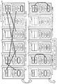
そして、図9の上段に示すように、各ノードのCM4は、HDDの未読み出しの情報ブロックを読出部42により読み出し、読み出した情報ブロックを通信部41によりリカバリ対象ブロックを有するノードへ転送する。情報ブロックを受信したノードは、キャッシュメモリ43に格納する。
Then, as shown in the upper part of FIG. 9, the
図9の例では、ノード−4及びノード−6は、それぞれHDD−4の3ブロック目の2D3及びHDD−6の2ブロック目の2Pをノード−1に転送し、ノード−3は、HDD−3の3ブロック目の3D1をノード−2に転送する。 In the example of FIG. 9, the node-4 and the node-6 transfer 2D3 of the third block of the HDD-4 and 2P of the second block of the HDD-6 to the node-1, respectively, and the node-3 transfers the HDD- 3D3 of the third block of 3 is transferred to node-2.
次いで、図9の下段に示すように、ノード−1及びノード−2のCM4は、書込部44により、キャッシュメモリ43の容量が枯渇したと判断して、ノード−1及びノード−2のそれぞれのリカバリ対象ブロックについて部分的なリカバリを実施する。このときノード−1及びノード−2のリカバリ対象ブロックに書き込まれる情報である2D4”及び3D3”は、それぞれ2D4”=2D4’+2P+2D3、3D3”=3D3’+3D2+3D1となる。なお、ノード−1の書込部44は、リカバリ対象ブロックから2D4’を読み出してから、読み出した2D4’とキャッシュメモリ43内の2P及び2D3とのXOR演算を行なう。また、ノード−2の書込部44は、リカバリ対象ブロックから3D3’を読み出してから、読み出した3D3’とキャッシュメモリ43内の3D2及び3D1とのXOR演算を行なう。
Next, as shown in the lower part of FIG. 9, the
一例として、図10に示すように、2P=000100、2D3=010011、3D2=011010、3D1=011001とした場合、2D4”及び3D3”はそれぞれ以下の値となる。 As an example, as shown in FIG. 10, when 2P = 000100, 2D3 = 000111, 3D2 = 0101010, 3D1 = 0101001, 2D4 ″ and 3D3 ″ have the following values, respectively.
2D4”=2D4’+2P +2D3=000011+000100+010011
=010100
3D3”=3D3’+3D2+3D1=011000+011010+011001
=011011
2D4 ″ = 2D4 ′ + 2P + 2D3 = 000011 + 000100 + 010011
= 010100
3D3 ″ = 3D3 ′ + 3D2 + 3D1 = 010001000 + 101010 + 101001
= 011011
ここで、2D4”及び3D3”のいずれについても、それぞれストライプ−2及びストライプ−3における消失ブロック(消失パリティ)以外の情報ブロックのXOR演算が完了しているため、ストライプ−2及びストライプ−3のリカバリが完了する。また、図10の下段に示すように、2D4”の値(010100)及び3D3”の値(011011)が、それぞれノード−5のHDD−5における2D4(010100)及び3D3(011011)と一致していることがわかる。 Here, for both 2D4 ″ and 3D3 ″, the XOR operation of the information blocks other than the lost blocks (erased parity) in stripe-2 and stripe-3 has been completed. Recovery is complete. Further, as shown in the lower part of FIG. 10, the value of 2D4 ″ (010100) and the value of 3D3 ″ (011011) coincide with 2D4 (010100) and 3D3 (011011) in the HDD-5 of the node-5, respectively. I understand that.
このように、第1実施形態においては、故障した記憶装置5の消失ブロック(第2ブロック情報)の復元先は、自装置10の1以上の第1記憶装置5又は自装置10とは異なる第2ストレージ装置10にそなえられた第1記憶装置5における空き記憶領域となる。この場合、通信部41は、読出部42により第1記憶装置5から読み出し済の第1ブロック情報を、復元先である第1記憶装置5へ送信するのである。
Thus, in the first embodiment, the restoration destination of the lost block (second block information) of the failed
〔1−5〕ストレージシステムの動作例
次に、上述の如く構成されたストレージシステム1の動作例を、図11〜図13を参照して説明する。
[1-5] Operation Example of Storage System Next, an operation example of the
〔1−5−1〕全体処理の説明
はじめに、図11を参照して、ストレージシステム1における全体の処理について説明する。
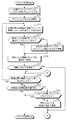
[1-5-1] Description of Overall Processing First, overall processing in the
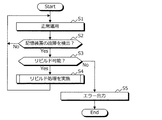
図11に示すように、ストレージシステム1が正常に運用されている状態において(ステップS1、ステップS2、及びステップS2のNoルート)、いずれかのストレージ装置10が記憶装置5の故障を検出すると(ステップS2のYesルート)、処理がステップS3に移行する。ステップS3では、各ストレージ装置10によりリビルドによる障害の復旧が可能か否かが判断される。
As shown in FIG. 11, in a state where the
リビルドによる障害の復旧が可能である場合(ステップS3のYesルート)、各ストレージ装置10は、リビルド処理を実施し(ステップS4)、処理がステップS1に移行する。一方、リビルドによる障害の復旧が不可能である場合(ステップS3のNoルート)、ストレージシステム1における少なくとも1つのストレージ装置10がシステムの管理者等へエラー出力を行ない(ステップS5)、処理が終了する。
When the failure can be recovered by rebuilding (Yes route in step S3), each
なお、リビルドによる障害の復旧が不可能である場合としては、少なくとも1つのストライプにおいて消失訂正符号の訂正能力を超えた情報ブロックの消失が生じた場合が挙げられる。また、エラー出力の手法としては、システムの管理者が使用する管理者端末へエラーの発生及びエラーの内容を含むメールを送信したり、管理者端末のモニタへエラー出力を行なう等、既知の種々の手法により行なうことが可能である。なお、管理者端末は、例えばスイッチ2及びネットワーク3、又はスイッチ6を介してストレージ装置10と相互に通信可能に接続されている。
In addition, as a case where the failure cannot be recovered by rebuilding, there is a case where an information block that exceeds the correction capability of the erasure correction code occurs in at least one stripe. In addition, as a method of error output, there are various known methods such as sending an email including an error occurrence and error content to an administrator terminal used by a system administrator, or outputting an error to a monitor of the administrator terminal. It is possible to carry out by this method. The administrator terminal is connected to the
〔1−5−2〕リビルド処理の説明
次に、図12及び図13を参照して、ストレージシステム1におけるリビルド処理(図11のステップS4参照)について説明する。
[1-5-2] Description of Rebuild Processing Next, the rebuild processing (see step S4 in FIG. 11) in the
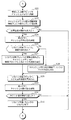
図12に示すように、はじめに、ストレージシステム1のストレージ装置10(CM4)は、記憶装置5の故障が発生したCM4の通信部41からの消失ブロックに関する情報の通知に基づき、CM4間でストライプごとのリカバリ対象ブロックを決定する(ステップS11)。例えば図5の上段に示す構成の場合、各ノードのCM4は、ノード−5のCM4からの通知に基づき、消失ブロックが存在するストライプ−1、ストライプ−2、ストライプ−3について、リカバリ対象ブロックに決定する。この場合、リカバリ対象ブロックは、ノード−1(ストライプ−2)、ノード−2(ストライプ−3)、ノード−6(ストライプ−1)の各記憶装置5の代替ブロックとなる。
As shown in FIG. 12, first, the storage device 10 (CM4) of the
次いで、各CM4は、書込部44によりキャッシュメモリ43の初期化を行なう(ステップS12)。なお、ステップS12の処理は、少なくともリカバリ対象ブロックを持つストレージ装置10のCM4が実施すればよい。
Next, each
また、CM4は、読出部42により記憶装置5の未読出の情報ブロックを物理アドレスの昇順で1つ読み出す(ステップS13)。なお、自装置10の記憶装置5にリカバリ対象ブロックが存在する場合、読出部42により読み出す情報ブロックには、当該リカバリ対象ブロックは含まれない。読出部42は、読み出す情報ブロックが当該リカバリ対象ブロックであれば、このブロックをスキップして次のアドレスの情報ブロックを読み出す。
Further, the
そして、各CM4は、読み出した情報ブロックが当該情報ブロックに対応するストライプの復旧先(転送先)のCM4でキャッシュメモリ43に格納可能か否かを判断する(ステップS14)。なお、この判断は、復旧先のCM4から、キャッシュメモリ43の容量が逼迫したことを示す通知等を受信しているか否かの判断により行なうことができる。
Each
このような通知を受信しておらず、復旧先のCM4で情報ブロックを格納可能である場合(ステップS14のYesルート)、処理がステップS16に移行する。一方、このような通知を受信しており、復旧先のCM4で情報ブロックを格納不可能である場合(ステップS14のNoルート)、CM4は、復旧先が情報ブロックを格納可能になるまで待機し(ステップS15)、格納可能になった旨の通知を受けると、処理がステップS16に移行する。なお、CM4は、この待機において、読み出した情報ブロックをキャッシュメモリ43に退避しておいてもよい。
When such a notification has not been received and the information block can be stored in the recovery destination CM 4 (Yes route in step S14), the process proceeds to step S16. On the other hand, when such a notification is received and the information block cannot be stored in the recovery destination CM 4 (No route in step S14), the
ステップS16では、CM4が読み出した情報ブロックを通信部41により復旧先のCM4へ転送する。
In step S16, the information block read by the
また、CM4が通信部41により他のCM4から情報ブロックを受信した場合(ステップS17及びステップS17のYesルート)、処理が図13のステップS22に移行する。なお、情報ブロックを受信したということは、自装置10の記憶装置5にリカバリ対象ブロックが存在することを意味する。
Further, when the
一方、CM4が他のCM4から情報ブロックを受信していない場合(ステップS17のNoルート)、CM4は読出部42により記憶装置5の最終ブロックまで読み出しが完了したか否かを判断する(ステップS18)。最終ブロックまで読み出しが完了していない場合(ステップS18のNoルート)、処理がステップS13に移行し、最後に読み出した情報ブロックの次のアドレスの情報ブロックを読み出す。
On the other hand, when the
また、ステップS18において、最終ブロックまで読み出しが完了した場合(ステップS18のYesルート)、自装置10の記憶装置5が復旧先でなければ(ステップS19及びステップS19のNoルート)、リビルド処理が終了する。なお、自装置10の記憶装置5が復旧先でないとは、自装置10の記憶装置がリカバリ対象ブロックを持っていない場合である。
In step S18, when the reading to the last block is completed (Yes route in step S18), if the
一方、自装置10の記憶装置5が復旧先であれば(ステップS19のYesルート)、CM4は、自装置10の記憶装置5に対するリカバリ対象ブロックのリカバリが完了しているか否かを判断する(ステップS20)。リカバリが完了している場合(ステップS20のYesルート)、リカバリ処理が終了する。また、リカバリが完了していない場合(ステップS20のNoルート)、CM4は、通信部41により他のCM4から情報ブロックを受信するまで待機し(ステップS21)、情報ブロックを受信すると、処理が図13のステップS22に移行する。
On the other hand, if the
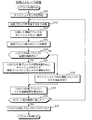
図13に示すように、ステップS22では、CM4の書込部44が、通信部41により受信した情報ブロックをキャッシュメモリ43へ格納する。そして、書込部44は、キャッシュメモリ43の容量を監視するための情報として、例えばキャッシュメモリ43の使用量を示す容量情報を更新する。また、リカバリ対象ブロックのリカバリが完了したか否かを判断するための情報として、例えば受信した(又はキャッシュメモリ43に格納した)情報ブロック数のカウント値を更新する(ステップS23)。なお、既述のように、キャッシュメモリの使用量についても情報ブロック数のカウント値が用いられてもよく、この場合、書込部44は、情報ブロック数のカウント値のみを更新すればよい。
As illustrated in FIG. 13, in step S <b> 22, the
次に、書込部44は、容量情報が閾値を超えたか否かを判断し(ステップS24)、超えていない場合(ステップS24のNoルート)、処理が図12のステップS18に移行する。
Next, the
一方、容量情報が閾値を超えた場合(ステップS24のYesルート)、書込部44は、容量情報が閾値を超えたこと(キャッシュ不可の旨)を通信部41を介して他のCM4に通知する(ステップS25)。そして、書込部44は、リカバリ対象ブロックに情報が格納済みであるか否かを判断する(ステップS26)。
On the other hand, when the capacity information exceeds the threshold value (Yes route in step S24), the
リカバリ対象ブロックに情報が格納済みである場合(ステップS26のYesルート)、書込部44は、リカバリ対象ブロックの情報を読み出す。そして、書込部44は、読み出した情報とキャッシュメモリ43内の情報ブロックとのXOR演算を実行し(ステップS27)、処理がステップS29に移行する。一方、リカバリ対象ブロックに情報が格納されていない場合(ステップS26のNoルート)、書込部44は、キャッシュメモリ43内の情報ブロックのXOR演算を実行し(ステップS28)、処理がステップS29に移行する。
When the information is already stored in the recovery target block (Yes route in step S26), the
ステップS29では、書込部44は、ステップS27又はステップS28におけるXOR演算結果をリカバリ対象ブロックへ書き込む。なお、キャッシュメモリ43の内容はリカバリ対象ブロックへ反映されたため、書込部44はキャッシュメモリ43をクリアする。また、書込部44は、キャッシュ可能の旨を通信部41を介して他のCM4に通知する(ステップS30)。
In step S29, the
そして、書込部44は、カウント値が閾値に達したか否かを判断し(ステップS31)、達していない場合(ステップS31のNoルート)、つまりリカバリが完了していない場合、処理が図12のステップS18に移行する。
Then, the
一方、カウント値が閾値に達した場合(ステップS31のYesルート)、書込部44は、リカバリ対象ブロックのリカバリが完了したと判断し(ステップS32)、処理が図12のステップS18に移行する。
On the other hand, when the count value reaches the threshold value (Yes route in step S31), the
このように、リビルド処理では、リカバリ対象ブロックを持たないCM4では読出処理(ステップS13〜S18)が主に実行され、リカバリ対象ブロックを持つCM4では読出処理と書込処理(ステップS17、ステップS20〜S32)とが実施される。
As described above, in the rebuild process, the read process (steps S13 to S18) is mainly executed in the
読出処理は、シーケンシャルリードによりスループットを向上させているため、読出処理の最中に書込処理が頻発すると、記憶装置5のアクセス先が変化してシーケンシャルなアクセスが阻害されてしまう。そこで、リカバリ対象ブロックを持つCM4は、受信した情報ブロックをキャッシュメモリ43に蓄積し、一括して書込処理を行なうことで、書込処理の実行頻度を低下させることができるのである。
Since the read process improves the throughput by sequential read, if the write process frequently occurs during the read process, the access destination of the
なお、図12のステップS17における情報ブロックの受信確認の処理は、ステップS13の前(ステップS18のNoルートからの合流後)等、任意のタイミングで行なわれてよい。また、図13のステップS23における情報ブロック数のカウント値の更新処理は、ステップS29の後等に行なわれてもよい。 Note that the information block reception confirmation processing in step S17 of FIG. 12 may be performed at any timing, such as before step S13 (after merging from the No route in step S18). Further, the update processing of the count value of the number of information blocks in step S23 of FIG. 13 may be performed after step S29 or the like.
〔2〕第2実施形態
上述した第1実施形態に係るストレージシステム1では、リカバリ対象ブロックに運用記憶装置5の代替ブロック(空き領域)が用いられるものとして説明したが、これに限定されるものではない。
[2] Second Embodiment In the
例えばストレージシステム1は、図14の上段に示すように、運用中のストレージ装置10(ノード−1〜ノード−6)の他に、待機用のストレージ装置10(ノード−7)をそなえてもよい。このとき、ストレージシステム1は、待機用のストレージ装置10のホットスワップディスクであるHDD−7上に、故障した記憶装置5(HDD−5)のデータを復元することができる。
For example, as shown in the upper part of FIG. 14, the
以下、第2実施形態に係るストレージシステム1について説明する。なお、ストレージシステム1及びストレージ装置10の構成及び機能は、特に言及しない限り、第1実施形態と基本的に同様とすることができる。
Hereinafter, the
第2実施形態に係るストレージシステム1では、記憶装置5が故障した場合の代替となる記憶装置5(HDD−7)を予め用意し、ホットスワップとしてシステムに組み込まれている。例えばノード−5のHDD−5が故障した場合、図14の上段に示すように、運用中のノード−1〜ノード−4及びノード−6は、それぞれ情報ブロックを待機用のノード−7へ送信する。情報ブロックは複数のノードから順次送られてくるため、情報ブロックを受信したノード−7は、各ストライプについてキャッシュメモリ43を用いて順次リカバリ対象ブロックへの書込処理(XOR演算)を行なう。
In the
このように、運用中のストレージ装置10では、消失ブロックのデータを復旧するための読出処理(シーケンシャルリード)を行ない、読み出した情報ブロックを待機用のストレージ装置10へ送信するだけでよく、書込処理は発生しない。一方、待機用のストレージ装置10では、情報ブロックを受信し、受信した情報ブロックの記憶装置5への書込処理(ランダムライト)を行なうだけでよい。
In this way, the
以上のように、第2実施形態に係るストレージシステム1では、復旧用の情報ブロックの読出要求と、復旧先での情報ブロックの書込要求とが別々の記憶装置5に発行されるため、シーケンシャルリードが中断されず、スループットをさらに向上させることができる。
As described above, in the
このため、第2実施形態に係るストレージシステム1では、運用中のストレージ装置10(CM4)は、例えば図4に示す機能のうち、少なくとも通信部41及び読出部42の機能をそなえていればよい。また、待機用のストレージ装置10(CM4)は、例えば図4に示す機能のうち、少なくとも通信部41、キャッシュメモリ43、及び書込部44の機能をそなえていればよい。
Therefore, in the
なお、図14に示す例では、ホットスワップディスクであるHDD−7が待機用のストレージ装置10にそなえられるものとして示したが、これに限定されるものではない。例えばHDD−7は、運用中のストレージ装置10(ノード−1〜ノード−4及びノード−6のいずれか)に追加してそなえられてもよい。この場合、運用中のストレージ装置10は、図4に示す通信部41、読出部42、キャッシュメモリ43、及び書込部44の全ての機能をそなえればよい。そして、当該ストレージ装置10は、例えばHDD−7以外のHDDから読出部42により情報ブロックを読み出してキャッシュメモリ43に格納し、キャッシュメモリ43内の情報ブロックを書込部44によりHDD−7のリカバリ対象ブロックへ反映すればよい。
In the example shown in FIG. 14, the HDD-7, which is a hot swap disk, is shown as being provided in the
なお、図14の例において、各ストライプの消失ブロックの復旧の進捗は、各記憶装置5での読出順序に関連して、図14の下段に示すように、先頭の情報ブロック、中央付近の情報ブロック、末尾の情報ブロックの順に、段階的に(この場合3段階で)行なわれる。
In the example of FIG. 14, the progress of recovery of the lost block in each stripe is related to the reading order in each
また、第2実施形態に係るストレージシステム1では、上述のように運用中のストレージ装置10における記憶装置5の代替ブロックは使用されない。換言すれば、第2実施形態に係るストレージシステム1としては、代替ブロックを持たない、例えば通常のRAID5やRAID6等を採用したストレージシステムを用いることもできる。
Further, in the
例えば図15の上段に示すように、消失訂正符号としてRAID5を採用したストレージシステム1は、図14と比較して、HDD−1が2D5を格納し、HDD−2が3D5を格納し、HDD−6が1D5を格納している。このような構成であっても、復旧用の情報ブロックはノード−7へ送信されるため、各ストレージ装置10は、図14を参照した説明と同様の処理を行なうことができる。
For example, as shown in the upper part of FIG. 15, in the
ところで、第2実施形態においては、消失ブロックに対応する全てのストライプについて、復旧用の情報ブロックが待機用の記憶装置5(ストレージ装置10)に送信されることになる。このため、待機用のストレージ装置10(CM4)では、大量の書込処理が発生することになる。 By the way, in the second embodiment, a recovery information block is transmitted to the standby storage device 5 (storage device 10) for all stripes corresponding to the lost block. Therefore, a large amount of writing processing occurs in the standby storage apparatus 10 (CM4).
そこで、待機用のストレージ装置10は、第1実施形態と比較して大容量のキャッシュメモリ43をそなえることが好ましい。これにより、1つのリカバリ対象ブロックについて或る程度の数の情報ブロックのXOR演算結果をまとめて反映できるため、1ブロック当たりの書込処理の発生頻度を低減させ、記憶装置5の処理負荷を低減させることができる。また、キャッシュメモリ43の容量の逼迫により運用中のストレージ装置10で送信待ちが発生する頻度も低減させることができ、リカバリ性能を向上させることができる。
Therefore, it is preferable that the
又は、待機用のストレージ装置10は、キャッシュメモリ43の容量が逼迫するよりも早いタイミングで、キャッシュメモリ43内の情報ブロックをリカバリ対象ブロックに反映してもよい。このタイミングとしては、例えば所定期間ごとが挙げられる。或いはキャッシュメモリ43の使用量の閾値を第1実施形態よりも小さい値とすることで、キャッシュメモリ43内の情報ブロックをパージする頻度を上げてもよい。
Alternatively, the
これにより、待機用の記憶装置5における1ブロック当たりの書込処理の発生頻度は増加するものの、キャッシュメモリ43の容量が逼迫する前にキャッシュメモリ43内の情報ブロックがリカバリ対象ブロックに反映される。従って、運用中のストレージ装置10で送信待ちが発生する頻度を低減させる、或いは無くすことができ、リカバリ性能を向上させることができる。
As a result, although the frequency of writing processing per block in the
このように、第2実施形態においては、故障した記憶装置5の消失ブロック(第2ブロック情報)の復元先は、故障した第2記憶装置5の代替となる第3記憶装置5における空き記憶領域となる。この場合、通信部41は、読出部42により第1記憶装置5から読み出し済の第1ブロック情報を、第3記憶装置5へ送信するのである。
In this way, in the second embodiment, the restoration destination of the lost block (second block information) of the failed
次に、図16〜図18を参照して、第2実施形態に係るストレージシステム1の動作例を説明する。なお、図16〜図18において、第1実施形態に係る図12及び図13に示す符号と同一の符号を付した処理は、図12及び図13に示す処理と基本的に同様の処理であるため、重複した説明を省略する。
Next, an operation example of the
第2実施形態に係るストレージシステム1では、運用ストレージ装置10と待機ストレージ装置10とで処理が異なる。
In the
例えば図16に示すように、運用ストレージ装置10の処理は、図12に示すストレージ装置10の処理から、ステップS12、ステップS17、及びステップS19〜S21の書込処理に係る処理を省略したものとなる。
For example, as shown in FIG. 16, the processing of the
また、図17に示すように、待機ストレージ装置10の処理は、図13に示すストレージ装置10の処理に対して、以下の処理を追加又は変更したものとなる。
Further, as shown in FIG. 17, the processing of the
例えば図17に示すように、待機ストレージ装置10のCM4は、リビルド処理において、キャッシュメモリ43を初期化し(ステップS41)、運用ストレージ装置10から情報ブロックを受信するまで待機する(ステップS42)。また、ステップS24において容量情報が閾値を超えていない場合(ステップS24のNoルート)、及びステップS31においてカウント値が閾値に達していない場合(ステップS31のNoルート)、処理がステップS42に移行する。その他の点については、待機ストレージ装置10の処理は図13に示すストレージ装置10の書込処理の動作と基本的に同様である。
For example, as shown in FIG. 17, the
なお、待機ストレージ装置10は、上述のようにキャッシュメモリ43の容量が逼迫するよりも早いタイミングでキャッシュメモリ43内の情報ブロックをリカバリ対象ブロックに反映してもよい。この場合、待機ストレージ装置10の処理は、図18に示すように、図17からステップS24、ステップS25、及びステップS30の処理を省略し、ステップS23の処理を情報ブロック数のカウント値の更新のみを行なうステップS51に置き換えたものとすることができる。
Note that the
以上のように、第2実施形態に係るストレージシステム1によっても、第1実施形態と同様の効果を奏することができるほか、CM4が記憶装置5から情報ブロックをよりシーケンシャルに読み出すことができ、スループットをさらに向上させることができる。
As described above, the
〔3〕ハードウェア構成例
図19に例示するように、上述した第1及び第2実施形態に係るストレージ装置10のCM4は、図1に示すCPU4a及びメモリ4bに加えて、記憶部4f、インタフェース部4g、入出力部4h、及び読取部4iをそなえることができる。
[3] Hardware Configuration Example As illustrated in FIG. 19, the
記憶部4fは、種々のデータやプログラム等を格納するハードウェアである。記憶部4fとしては、例えばHDD等の磁気ディスク装置、SSD等の半導体ドライブ装置、フラッシュメモリやROM等の不揮発性メモリ等の各種装置が挙げられる。
The
例えば記憶部4fは、ストレージ装置10(CM4)の各種機能の全部もしくは一部を実現するリカバリプログラム40を格納することができる。CPU4aは、例えば記憶部4fに格納されたリカバリプログラム40をメモリ4b等の記憶装置に展開して実行することにより、故障した記憶装置5の消失ブロックをリカバリ(復旧)することでリビルドを行なう上述したストレージ装置10(CM4)の機能を実現することができる。
For example, the
インタフェース部4gは、有線又は無線による、スイッチ2及び6、並びに記憶装置5等との間の接続及び通信の制御等を行なう通信インタフェースである。なお、図1に示すIF4c〜4eは、インタフェース部4gの一例である。
The interface unit 4g is a communication interface that performs connection and communication control between the
入出力部4hは、マウス、キーボード、タッチパネル、音声操作のためのマイク等の入力装置(操作部)、並びにディスプレイ、スピーカ、及びプリンタ等の出力装置(出力部、表示部)の少なくとも一方を含むことができる。例えば入力装置は、管理者等による各種操作やデータの入力等の作業に用いられてよく、出力装置は、各種通知等の出力に用いられてよい。 The input / output unit 4h includes at least one of an input device (operation unit) such as a mouse, a keyboard, a touch panel, a microphone for voice operation, and an output device (output unit, display unit) such as a display, a speaker, and a printer. be able to. For example, the input device may be used for operations such as various operations and data input by an administrator or the like, and the output device may be used for outputting various notifications.
読取部4iは、コンピュータ読取可能な記録媒体4jに記録されたデータやプログラムを読み出す装置である。この記録媒体4jにはリカバリプログラム40が格納されてもよい。
The
なお、記録媒体4jとしては、例えばフレキシブルディスク、CD、DVD、ブルーレイディスク等の光ディスクや、USBメモリやSDカード等のフラッシュメモリ等の非一時的な記録媒体が挙げられる。なお、CDとしては、CD−ROM、CD−R、CD−RW等が挙げられる。また、DVDとしては、DVD−ROM、DVD−RAM、DVD−R、DVD−RW、DVD+R、DVD+RW等が挙げられる。
Examples of the
上述したストレージ装置10のハードウェア構成は例示である。従って、ストレージ装置10内でのハードウェアの増減(例えば任意のブロックの追加や省略)、分割、任意の組み合わせでの統合、バスの追加又は省略等は適宜行なわれてもよい。
The hardware configuration of the
〔4〕その他
以上、本発明の好ましい実施形態について詳述したが、本発明は、かかる特定の実施形態に限定されるものではなく、本発明の趣旨を逸脱しない範囲内において、種々の変形、変更して実施することができる。
[4] Others While the preferred embodiments of the present invention have been described in detail above, the present invention is not limited to such specific embodiments, and various modifications and changes can be made without departing from the spirit of the present invention. It can be changed and implemented.
例えば、図4に示すストレージ装置10(CM4)の各機能ブロックは、任意の組み合わせで併合してもよく、分割してもよい。 For example, the functional blocks of the storage apparatus 10 (CM4) shown in FIG. 4 may be merged in an arbitrary combination or may be divided.
また、ここまで、ストレージシステム1が複数のストレージ装置10(筐体)をそなえるクラスタ構成の分散ストレージシステムであるものとして説明したが、これに限定されるものではない。例えばストレージシステム1は、図20に示すように、単一のストレージ装置10内にJBOD(Just a Brunck of Disks)50等の形態で実装されたディスクアレイをそなえてもよい。
Further, the
JBOD50は、複数の記憶装置5を搭載し、複数の記憶装置5に接続されたIF50aを介してCM4のIF4dと通信を行なうことができる。この場合、CM4は、読出部42により複数の記憶装置5からシーケンシャルに読み出した情報ブロックを、書込部44によりキャッシュメモリ43に格納すればよい。そして、CM4は、キャッシュメモリ43の容量が逼迫した場合に、キャッシュメモリ43内の情報ブロックを復旧先の記憶装置5のリカバリ対象ブロックに反映すればよい。
The
なお、図20に例示する構成において、CM4は図4に示す通信部41、読出部42、キャッシュメモリ43、及び書込部44をそなえることができる。例えば読出部42は、記憶装置5から情報ブロックをシーケンシャルに読み出して通信部41に出力する。この情報ブロックは、通信部41を介して書込部44によりキャッシュメモリ43に格納され、リカバリ対象ブロックを有する記憶装置5へ書き込まれる。
In the configuration illustrated in FIG. 20, the
このように、図20及び図4に例示する構成において、キャッシュメモリ43は、通信部41から入力される第1ブロック情報を保持する保持部の一例であるといえる。また、書込部44は、通信部41から入力された第1ブロック情報に基づき、第2ブロック情報を段階的に復元する復元部の一例であるといえる。
As described above, in the configuration illustrated in FIGS. 20 and 4, the
なお、ストレージシステム1は、複数のストレージ装置10(クラスタノード)内にそれぞれJBOD50等により複数の記憶装置5を搭載する、図1及び図20の双方の形態を持つ構成であってもよい。
Note that the
〔5〕付記
以上の第1及び第2実施形態に関し、更に以下の付記を開示する。
[5] Supplementary Notes Regarding the above first and second embodiments, the following supplementary notes are further disclosed.
(付記1)
1以上の第1記憶装置と、
前記1以上の第1記憶装置が記憶する複数の第1ブロック情報であって、故障した第2記憶装置が記憶する複数の第2ブロック情報の復元に用いられる前記複数の第1ブロック情報を、前記1以上の第1記憶装置から記憶領域のアドレス順に読み出す読出部と、
前記読出部により前記1以上の第1記憶装置から読み出し済の第1ブロック情報を、前記複数の第2ブロック情報を段階的に復元するために、前記複数の第2ブロック情報の復元先へ出力する出力部と、をそなえることを特徴とする、ストレージ装置。
(Appendix 1)
One or more first storage devices;
The plurality of first block information stored in the one or more first storage devices, the plurality of first block information used for restoring the plurality of second block information stored in the failed second storage device, A reading unit that reads from the one or more first storage devices in the order of storage area addresses;
The first block information read from the one or more first storage devices by the reading unit is output to the restoration destination of the plurality of second block information in order to restore the plurality of second block information in stages. And a storage device.
(付記2)
前記ストレージ装置とは異なる第1ストレージ装置、又は、前記出力部、から入力された第1ブロック情報に基づき、前記第2ブロック情報を段階的に復元する復元部をさらにそなえることを特徴とする、付記1記載のストレージ装置。
(Appendix 2)
The image processing apparatus further includes a restoration unit that restores the second block information in stages based on first block information input from a first storage device different from the storage device or the output unit. The storage device according to
(付記3)
前記復元部は、前記入力された第1ブロック情報及び前記第2ブロック情報の復元先が記憶する情報を用いて、消失訂正符号に基づく演算を行ない、演算結果を前記第2ブロック情報の復元先へ書き込むことを特徴とする、付記2記載のストレージ装置。
(Appendix 3)
The restoration unit performs an operation based on an erasure correction code using information stored in the restoration destination of the input first block information and the second block information, and obtains a computation result as the restoration destination of the second block information. The storage device according to
(付記4)
前記第1ストレージ装置又は前記出力部から入力される第1ブロック情報を保持する保持部をさらにそなえ、
前記復元部は、所定のタイミングで、前記保持部が保持する1以上の第1ブロック情報に基づき、前記第2ブロック情報を段階的に復元することを特徴とする、付記2又は付記3記載のストレージ装置。
(Appendix 4)
A storage unit for storing first block information input from the first storage device or the output unit;
The
(付記5)
前記第2ブロック情報の復元先は、前記1以上の第1記憶装置、又は、前記ストレージ装置とは異なる第2ストレージ装置にそなえられた第1記憶装置における空き記憶領域であり、
前記出力部は、前記読出部により前記第1記憶装置から読み出し済の第1ブロック情報を、前記復元先である第1記憶装置へ送信することを特徴とする、付記1〜4のいずれか1項記載のストレージ装置。
(Appendix 5)
The restoration destination of the second block information is a free storage area in the first storage device provided in the one or more first storage devices or a second storage device different from the storage device,
The output unit transmits the first block information that has been read from the first storage device by the reading unit to the first storage device that is the restoration destination. The storage device described in the item.
(付記6)
前記第2ブロック情報の復元先は、前記故障した第2記憶装置の代替となる第3記憶装置における空き記憶領域であり、
前記出力部は、前記読出部により前記第1記憶装置から読み出し済の第1ブロック情報を、前記第3記憶装置へ送信することを特徴とする、付記1〜4のいずれか1項記載のストレージ装置。
(Appendix 6)
The restoration destination of the second block information is an empty storage area in a third storage device that is a substitute for the failed second storage device,
The storage according to any one of
(付記7)
複数の記憶装置と、
前記複数の記憶装置のうちの複数の第1記憶装置の各々が記憶する複数の第1ブロック情報に基づき、前記複数の記憶装置のうちの故障した第2記憶装置が記憶する複数の第2ブロック情報を復元する1以上のストレージ装置と、をそなえ、
前記1以上のストレージ装置は、
複数の第1記憶装置の各々から、前記複数の第1ブロック情報を記憶領域のアドレス順に読み出し、
前記読み出しの処理において前記複数の第1記憶装置の各々から読み出し済の第1ブロック情報に基づき、前記複数の第2ブロック情報を段階的に復元する、
ことを特徴とする、ストレージシステム。
(Appendix 7)
A plurality of storage devices;
A plurality of second blocks stored in the failed second storage device among the plurality of storage devices based on a plurality of first block information stored in each of the plurality of first storage devices among the plurality of storage devices. Including at least one storage device for restoring information,
The one or more storage devices are:
Reading the plurality of first block information from each of the plurality of first storage devices in the order of addresses of the storage areas;
Based on the first block information read from each of the plurality of first storage devices in the reading process, the plurality of second block information is restored in stages.
A storage system characterized by that.
(付記8)
コンピュータに、
1以上の第1記憶装置が記憶する複数の第1ブロック情報であって、故障した第2記憶装置が記憶する複数の第2ブロック情報の復元に用いられる前記複数の第1ブロック情報を、前記1以上の第1記憶装置から記憶領域のアドレス順に読み出し、
前記読み出しの処理において前記1以上の第1記憶装置から読み出し済の第1ブロック情報を、前記複数の第2ブロック情報を段階的に復元するために、前記複数の第2ブロック情報の復元先へ出力する、
処理を実行させることを特徴とする、リカバリプログラム。
(Appendix 8)
On the computer,
The plurality of first block information stored in one or more first storage devices, the plurality of first block information used for restoring the plurality of second block information stored in the failed second storage device, Read from one or more first storage devices in the order of addresses in the storage area,
The first block information that has been read from the one or more first storage devices in the reading process is restored to the restoration destination of the plurality of second block information in order to restore the plurality of second block information in stages. Output,
A recovery program characterized by causing a process to be executed.
(付記9)
複数の記憶装置と、前記複数の記憶装置に対する制御を行なう1以上のストレージ装置とをそなえるストレージシステムにおけるリカバリ方法であって、
前記1以上のストレージ装置は、
前記複数の記憶装置のうちの複数の第1記憶装置の各々が記憶する複数の第1ブロック情報に基づき、前記複数の記憶装置のうちの故障した第2記憶装置が記憶する複数の第2ブロック情報を復元し、
前記復元の処理において、
前記1以上のストレージ装置により、
複数の第1記憶装置の各々から、前記複数の第1ブロック情報を記憶領域のアドレス順に読み出し、
前記読み出しの処理において前記複数の第1記憶装置の各々から読み出し済の第1ブロック情報に基づき、前記複数の第2ブロック情報を段階的に復元する、
ことを特徴とする、リカバリ方法。
(Appendix 9)
A recovery method in a storage system comprising a plurality of storage devices and one or more storage devices that control the plurality of storage devices,
The one or more storage devices are:
A plurality of second blocks stored in the failed second storage device among the plurality of storage devices based on a plurality of first block information stored in each of the plurality of first storage devices among the plurality of storage devices. Restore information,
In the restoration process,
With the one or more storage devices,
Reading the plurality of first block information from each of the plurality of first storage devices in the order of addresses of the storage areas;
Based on the first block information read from each of the plurality of first storage devices in the reading process, the plurality of second block information is restored in stages.
The recovery method characterized by the above-mentioned.
1 ストレージシステム
2,6 スイッチ
3 ネットワーク
4 コントローラモジュール
4a CPU
4b メモリ
4c〜4e,50a インタフェース
4f 記憶部
4g インタフェース部
4h 入出力部
4i 読取部
4j 記録媒体
5,5−1〜5−n 記憶装置
10,10−1〜10−m ストレージ装置
40 リカバリプログラム
41 通信部
42 読出部
43 キャッシュメモリ
44 書込部
50 JBOD
1
Claims (8)
前記1以上の第1記憶装置が記憶する複数の第1ブロック情報であって、故障した第2記憶装置が記憶する複数の第2ブロック情報の復元に用いられる前記複数の第1ブロック情報を、前記1以上の第1記憶装置から記憶領域のアドレス順に読み出す読出部と、
前記読出部により前記1以上の第1記憶装置から読み出し済の第1ブロック情報を、前記複数の第2ブロック情報を段階的に復元するために、前記複数の第2ブロック情報の復元先へ出力する出力部と、をそなえることを特徴とする、ストレージ装置。 One or more first storage devices;
The plurality of first block information stored in the one or more first storage devices, the plurality of first block information used for restoring the plurality of second block information stored in the failed second storage device, A reading unit that reads from the one or more first storage devices in the order of storage area addresses;
The first block information read from the one or more first storage devices by the reading unit is output to the restoration destination of the plurality of second block information in order to restore the plurality of second block information in stages. And a storage device.
前記復元部は、所定のタイミングで、前記保持部が保持する1以上の第1ブロック情報に基づき、前記第2ブロック情報を段階的に復元することを特徴とする、請求項2記載のストレージ装置。 A storage unit for storing first block information input from the first storage device or the output unit;
The storage apparatus according to claim 2, wherein the restoration unit restores the second block information in a stepwise manner based on one or more pieces of first block information held by the holding unit at a predetermined timing. .
前記出力部は、前記読出部により前記第1記憶装置から読み出し済の第1ブロック情報を、前記第2ストレージ装置へ送信することを特徴とする、請求項1〜3のいずれか1項記載のストレージ装置。 The restoration destination of the second block information is a free storage area in a first storage device provided in a second storage device different from the storage device,
The said output part transmits the 1st block information already read from the said 1st storage device by the said reading part to the said 2nd storage apparatus, The any one of Claims 1-3 characterized by the above-mentioned. Storage device.
前記出力部は、前記読出部により前記第1記憶装置から読み出し済の第1ブロック情報を、前記第3記憶装置へ送信することを特徴とする、請求項1〜3のいずれか1項記載のストレージ装置。 The restoration destination of the second block information is an empty storage area in a third storage device that is a substitute for the failed second storage device,
The said output part transmits the 1st block information already read from the said 1st memory | storage device by the said reading part to the said 3rd memory | storage device, The any one of Claims 1-3 characterized by the above-mentioned. Storage device.
前記複数の記憶装置のうちの複数の第1記憶装置の各々が記憶する複数の第1ブロック情報に基づき、前記複数の記憶装置のうちの故障した第2記憶装置が記憶する複数の第2ブロック情報を復元する1以上のストレージ装置と、をそなえ、
前記1以上のストレージ装置は、
複数の第1記憶装置の各々から、前記複数の第1ブロック情報を記憶領域のアドレス順に読み出し、
前記読み出しの処理において前記複数の第1記憶装置の各々から読み出し済の第1ブロック情報に基づき、前記複数の第2ブロック情報を段階的に復元する、
ことを特徴とする、ストレージシステム。 A plurality of storage devices;
A plurality of second blocks stored in the failed second storage device among the plurality of storage devices based on a plurality of first block information stored in each of the plurality of first storage devices among the plurality of storage devices. Including at least one storage device for restoring information,
The one or more storage devices are:
Reading the plurality of first block information from each of the plurality of first storage devices in the order of addresses of the storage areas;
Based on the first block information read from each of the plurality of first storage devices in the reading process, the plurality of second block information is restored in stages.
A storage system characterized by that.
1以上の第1記憶装置が記憶する複数の第1ブロック情報であって、故障した第2記憶装置が記憶する複数の第2ブロック情報の復元に用いられる前記複数の第1ブロック情報を、前記1以上の第1記憶装置から記憶領域のアドレス順に読み出し、
前記読み出しの処理において前記1以上の第1記憶装置から読み出し済の第1ブロック情報を、前記複数の第2ブロック情報を段階的に復元するために、前記複数の第2ブロック情報の復元先へ出力する、
処理を実行させることを特徴とする、リカバリプログラム。 On the computer,
The plurality of first block information stored in one or more first storage devices, the plurality of first block information used for restoring the plurality of second block information stored in the failed second storage device, Read from one or more first storage devices in the order of addresses in the storage area,
The first block information that has been read from the one or more first storage devices in the reading process is restored to the restoration destination of the plurality of second block information in order to restore the plurality of second block information in stages. Output,
A recovery program characterized by causing a process to be executed.
前記1以上のストレージ装置は、
前記複数の記憶装置のうちの複数の第1記憶装置の各々が記憶する複数の第1ブロック情報に基づき、前記複数の記憶装置のうちの故障した第2記憶装置が記憶する複数の第2ブロック情報を復元し、
前記復元の処理において、
前記1以上のストレージ装置により、
複数の第1記憶装置の各々から、前記複数の第1ブロック情報を記憶領域のアドレス順に読み出し、
前記読み出しの処理において前記複数の第1記憶装置の各々から読み出し済の第1ブロック情報に基づき、前記複数の第2ブロック情報を段階的に復元する、
ことを特徴とする、リカバリ方法。 A recovery method in a storage system comprising a plurality of storage devices and one or more storage devices that control the plurality of storage devices,
The one or more storage devices are:
A plurality of second blocks stored in the failed second storage device among the plurality of storage devices based on a plurality of first block information stored in each of the plurality of first storage devices among the plurality of storage devices. Restore information,
In the restoration process,
With the one or more storage devices,
Reading the plurality of first block information from each of the plurality of first storage devices in the order of addresses of the storage areas;
Based on the first block information read from each of the plurality of first storage devices in the reading process, the plurality of second block information is restored in stages.
The recovery method characterized by the above-mentioned.
Priority Applications (2)
| Application Number | Priority Date | Filing Date | Title |
|---|---|---|---|
| JP2015037096A JP6536083B2 (en) | 2015-02-26 | 2015-02-26 | Storage device, storage system, and recovery program |
| US15/045,495 US10133640B2 (en) | 2015-02-26 | 2016-02-17 | Storage apparatus and storage system |
Applications Claiming Priority (1)
| Application Number | Priority Date | Filing Date | Title |
|---|---|---|---|
| JP2015037096A JP6536083B2 (en) | 2015-02-26 | 2015-02-26 | Storage device, storage system, and recovery program |
Publications (2)
| Publication Number | Publication Date |
|---|---|
| JP2016161970A true JP2016161970A (en) | 2016-09-05 |
| JP6536083B2 JP6536083B2 (en) | 2019-07-03 |
Family
ID=56798333
Family Applications (1)
| Application Number | Title | Priority Date | Filing Date |
|---|---|---|---|
| JP2015037096A Expired - Fee Related JP6536083B2 (en) | 2015-02-26 | 2015-02-26 | Storage device, storage system, and recovery program |
Country Status (2)
| Country | Link |
|---|---|
| US (1) | US10133640B2 (en) |
| JP (1) | JP6536083B2 (en) |
Cited By (2)
| Publication number | Priority date | Publication date | Assignee | Title |
|---|---|---|---|---|
| WO2018138813A1 (en) * | 2017-01-25 | 2018-08-02 | 株式会社日立製作所 | Computer system |
| JP2023099186A (en) * | 2018-06-12 | 2023-07-11 | ウェカ.アイオー リミテッド | Storage system spanning multiple failure domains |
Families Citing this family (1)
| Publication number | Priority date | Publication date | Assignee | Title |
|---|---|---|---|---|
| US11157179B2 (en) * | 2019-12-03 | 2021-10-26 | Pure Storage, Inc. | Dynamic allocation of blocks of a storage device based on power loss protection |
Citations (2)
| Publication number | Priority date | Publication date | Assignee | Title |
|---|---|---|---|---|
| JP2007513435A (en) * | 2003-12-29 | 2007-05-24 | インテル・コーポレーション | Method, system, and program for managing data organization |
| US20110208994A1 (en) * | 2010-02-22 | 2011-08-25 | International Business Machines Corporation | Rebuilding lost data in a distributed redundancy data storage system |
Family Cites Families (8)
| Publication number | Priority date | Publication date | Assignee | Title |
|---|---|---|---|---|
| US4368513A (en) * | 1980-03-24 | 1983-01-11 | International Business Machines Corp. | Partial roll mode transfer for cyclic bulk memory |
| US7363316B2 (en) * | 2004-08-30 | 2008-04-22 | Mendocino Software, Inc. | Systems and methods for organizing and mapping data |
| US7634686B2 (en) * | 2006-07-24 | 2009-12-15 | Marvell World Trade Ltd. | File server for redundant array of independent disks (RAID) system |
| US8046629B1 (en) * | 2006-07-24 | 2011-10-25 | Marvell World Trade Ltd. | File server for redundant array of independent disks (RAID) system |
| US7992037B2 (en) | 2008-09-11 | 2011-08-02 | Nec Laboratories America, Inc. | Scalable secondary storage systems and methods |
| US9367243B1 (en) * | 2014-06-04 | 2016-06-14 | Pure Storage, Inc. | Scalable non-uniform storage sizes |
| US9087012B1 (en) * | 2014-06-04 | 2015-07-21 | Pure Storage, Inc. | Disaster recovery at high reliability in a storage cluster |
| US9495255B2 (en) * | 2014-08-07 | 2016-11-15 | Pure Storage, Inc. | Error recovery in a storage cluster |
-
2015
- 2015-02-26 JP JP2015037096A patent/JP6536083B2/en not_active Expired - Fee Related
-
2016
- 2016-02-17 US US15/045,495 patent/US10133640B2/en active Active
Patent Citations (2)
| Publication number | Priority date | Publication date | Assignee | Title |
|---|---|---|---|---|
| JP2007513435A (en) * | 2003-12-29 | 2007-05-24 | インテル・コーポレーション | Method, system, and program for managing data organization |
| US20110208994A1 (en) * | 2010-02-22 | 2011-08-25 | International Business Machines Corporation | Rebuilding lost data in a distributed redundancy data storage system |
Cited By (3)
| Publication number | Priority date | Publication date | Assignee | Title |
|---|---|---|---|---|
| WO2018138813A1 (en) * | 2017-01-25 | 2018-08-02 | 株式会社日立製作所 | Computer system |
| JP2023099186A (en) * | 2018-06-12 | 2023-07-11 | ウェカ.アイオー リミテッド | Storage system spanning multiple failure domains |
| JP7512472B2 (en) | 2018-06-12 | 2024-07-08 | ウェカ.アイオー リミテッド | Storage systems spanning multiple failure domains |
Also Published As
| Publication number | Publication date |
|---|---|
| JP6536083B2 (en) | 2019-07-03 |
| US10133640B2 (en) | 2018-11-20 |
| US20160253242A1 (en) | 2016-09-01 |
Similar Documents
| Publication | Publication Date | Title |
|---|---|---|
| JP4876187B2 (en) | Apparatus and method for selecting a deduplication protocol for a data storage library | |
| US8060772B2 (en) | Storage redundant array of independent drives | |
| KR102102728B1 (en) | Scalable storage protection | |
| US12066894B2 (en) | Storage system | |
| US9389975B2 (en) | Method and apparatus to utilize large capacity disk drives | |
| KR101824286B1 (en) | Reconstruct reads in a raid array with dynamic geometries | |
| US9817715B2 (en) | Resiliency fragment tiering | |
| JP5038897B2 (en) | Storage of parity information for data recovery | |
| JP5124792B2 (en) | File server for RAID (Redundant Array of Independent Disks) system | |
| JP2008046986A (en) | Storage system | |
| GB2418769A (en) | Storing data across a plurality of disks | |
| KR20130118876A (en) | Adaptive raid for an ssd environment | |
| CN101517542A (en) | Method for optimized reconstruction and copyback of disconnected drives in the presence of a global hot spare disk | |
| JP2018508073A (en) | Data removal, allocation and reconstruction | |
| US8433949B2 (en) | Disk array apparatus and physical disk restoration method | |
| JP6536083B2 (en) | Storage device, storage system, and recovery program | |
| US20180307427A1 (en) | Storage control apparatus and storage control method | |
| Qiao et al. | Incorporate proactive data protection in ZFS towards reliable storage systems | |
| JP5640618B2 (en) | Management program, management apparatus, and management method | |
| CN102819406A (en) | Front-end data storage method and device | |
| JP2022101208A (en) | Distributed storage system, data restoration method, and data processing program | |
| JP5643238B2 (en) | Disk array control device, disk array device, and disk array control method |
Legal Events
| Date | Code | Title | Description |
|---|---|---|---|
| A621 | Written request for application examination |
Free format text: JAPANESE INTERMEDIATE CODE: A621 Effective date: 20171215 |
|
| A977 | Report on retrieval |
Free format text: JAPANESE INTERMEDIATE CODE: A971007 Effective date: 20180831 |
|
| A131 | Notification of reasons for refusal |
Free format text: JAPANESE INTERMEDIATE CODE: A131 Effective date: 20180925 |
|
| A521 | Request for written amendment filed |
Free format text: JAPANESE INTERMEDIATE CODE: A523 Effective date: 20181122 |
|
| TRDD | Decision of grant or rejection written | ||
| A01 | Written decision to grant a patent or to grant a registration (utility model) |
Free format text: JAPANESE INTERMEDIATE CODE: A01 Effective date: 20190507 |
|
| A61 | First payment of annual fees (during grant procedure) |
Free format text: JAPANESE INTERMEDIATE CODE: A61 Effective date: 20190520 |
|
| R150 | Certificate of patent or registration of utility model |
Ref document number: 6536083 Country of ref document: JP Free format text: JAPANESE INTERMEDIATE CODE: R150 |
|
| LAPS | Cancellation because of no payment of annual fees |