JP2016158721A - Ophthalmologic apparatus - Google Patents
Ophthalmologic apparatus Download PDFInfo
- Publication number
- JP2016158721A JP2016158721A JP2015038297A JP2015038297A JP2016158721A JP 2016158721 A JP2016158721 A JP 2016158721A JP 2015038297 A JP2015038297 A JP 2015038297A JP 2015038297 A JP2015038297 A JP 2015038297A JP 2016158721 A JP2016158721 A JP 2016158721A
- Authority
- JP
- Japan
- Prior art keywords
- eye
- fixation
- presentation position
- light
- optical system
- Prior art date
- Legal status (The legal status is an assumption and is not a legal conclusion. Google has not performed a legal analysis and makes no representation as to the accuracy of the status listed.)
- Pending
Links
- 230000003287 optical effect Effects 0.000 claims abstract description 161
- 230000008859 change Effects 0.000 claims abstract description 53
- 210000004087 cornea Anatomy 0.000 claims description 54
- 238000005286 illumination Methods 0.000 claims description 23
- 210000002889 endothelial cell Anatomy 0.000 claims description 16
- 210000001747 pupil Anatomy 0.000 claims description 8
- 230000007246 mechanism Effects 0.000 claims description 7
- 230000000007 visual effect Effects 0.000 claims description 4
- 238000006073 displacement reaction Methods 0.000 claims description 2
- 230000001678 irradiating effect Effects 0.000 claims description 2
- 238000003384 imaging method Methods 0.000 abstract description 73
- 238000001514 detection method Methods 0.000 description 20
- 238000000034 method Methods 0.000 description 19
- 230000008569 process Effects 0.000 description 16
- 230000003511 endothelial effect Effects 0.000 description 11
- 210000000399 corneal endothelial cell Anatomy 0.000 description 7
- 210000000871 endothelium corneal Anatomy 0.000 description 5
- 230000004397 blinking Effects 0.000 description 4
- 238000010586 diagram Methods 0.000 description 3
- 210000003038 endothelium Anatomy 0.000 description 3
- 230000002093 peripheral effect Effects 0.000 description 3
- 238000005516 engineering process Methods 0.000 description 2
- 210000003560 epithelium corneal Anatomy 0.000 description 2
- 230000006870 function Effects 0.000 description 2
- 230000004459 microsaccades Effects 0.000 description 2
- 238000012935 Averaging Methods 0.000 description 1
- 206010025421 Macule Diseases 0.000 description 1
- 230000004323 axial length Effects 0.000 description 1
- 230000000295 complement effect Effects 0.000 description 1
- 230000000694 effects Effects 0.000 description 1
- 238000005401 electroluminescence Methods 0.000 description 1
- 230000004424 eye movement Effects 0.000 description 1
- 239000004973 liquid crystal related substance Substances 0.000 description 1
- 238000005259 measurement Methods 0.000 description 1
- 229910044991 metal oxide Inorganic materials 0.000 description 1
- 150000004706 metal oxides Chemical class 0.000 description 1
- 230000004044 response Effects 0.000 description 1
- 239000004065 semiconductor Substances 0.000 description 1
Images


Classifications
-
- A—HUMAN NECESSITIES
- A61—MEDICAL OR VETERINARY SCIENCE; HYGIENE
- A61B—DIAGNOSIS; SURGERY; IDENTIFICATION
- A61B3/00—Apparatus for testing the eyes; Instruments for examining the eyes
- A61B3/10—Objective types, i.e. instruments for examining the eyes independent of the patients' perceptions or reactions
- A61B3/113—Objective types, i.e. instruments for examining the eyes independent of the patients' perceptions or reactions for determining or recording eye movement
-
- A—HUMAN NECESSITIES
- A61—MEDICAL OR VETERINARY SCIENCE; HYGIENE
- A61B—DIAGNOSIS; SURGERY; IDENTIFICATION
- A61B3/00—Apparatus for testing the eyes; Instruments for examining the eyes
- A61B3/10—Objective types, i.e. instruments for examining the eyes independent of the patients' perceptions or reactions
- A61B3/14—Arrangements specially adapted for eye photography
- A61B3/15—Arrangements specially adapted for eye photography with means for aligning, spacing or blocking spurious reflection ; with means for relaxing
- A61B3/152—Arrangements specially adapted for eye photography with means for aligning, spacing or blocking spurious reflection ; with means for relaxing for aligning
Abstract
Description
本開示は、固視灯の呈示位置を複数の位置に切換えることができる眼科装置に関する。 The present disclosure relates to an ophthalmologic apparatus capable of switching a fixation lamp presenting position to a plurality of positions.
従来より、眼科装置において、被検眼に対して固視標を呈示することによって、被検眼を固視させた状態で、被検眼の観察、撮影、或いは検査(以下、まとめて「検眼」と称す)を行う装置が知られている。このような装置には、固視灯の呈示位置を、複数の呈示位置に切換えることによって、検眼が行われる被検眼の位置を変更する機構が設けられている場合がある。 Conventionally, in an ophthalmologic apparatus, by presenting a fixation target to an eye to be examined, the eye to be examined is observed, photographed, or examined (hereinafter collectively referred to as “optometry”). ) Is known. Such a device may be provided with a mechanism for changing the position of the eye to be examined by switching the presenting position of the fixation lamp to a plurality of presenting positions.
例えば、特許文献1には、光軸に対して交差する平面上の異なる位置に配置された複数の固視灯を持ち、点灯される固視灯を切換えながら、角膜の複数箇所における内皮細胞画像を撮影する装置が記載されている。 For example, Patent Document 1 has a plurality of fixation lamps arranged at different positions on a plane that intersects the optical axis, and switches the fixation lamps to be lit while switching endothelial cell images at a plurality of locations on the cornea. A device for taking pictures is described.
しかし、固視標の呈示位置を切換えつつ検眼を行う場合に、被検者が固視標を適正に固視できず、固視不良のまま検眼が行われてしまう場合があった。この場合、所望の位置についての検眼結果が得られない可能性が高い。 However, when performing an optometry while switching the fixation target presentation position, the subject may not be able to fixate the fixation target properly, and the optometry may be performed with poor fixation. In this case, there is a high possibility that an optometry result for a desired position cannot be obtained.
本開示は、従来技術の問題点に鑑みてなされたものであり、固視が行われた状態での検眼をスムースに行いやすい眼科装置を提供すること目的とする。 The present disclosure has been made in view of the problems of the prior art, and an object thereof is to provide an ophthalmologic apparatus that can easily perform optometry in a state in which fixation is performed.
本開示の第1態様に係る眼科装置は、被検眼に呈示される固視標を有し、被検眼の視線方向を変更するために前記固視標の呈示位置を切換可能な固視光学系と、前記被検眼の視線方向に関する情報である視線方向情報を検出する視線方向情報検出手段と、前記固視標の呈示位置が第1呈示位置から前記第1呈示位置とは異なる第2呈示位置へと切換えられる場合に、前記固視標の呈示位置の切換に伴い前記被検眼の視線方向が変化したか否かを、前記固視標の呈示位置が切換わる前後での前記視線方向情報の変化に基づいて判定する判定手段と、を備える。 An ophthalmologic apparatus according to a first aspect of the present disclosure has a fixation target presented to an eye to be examined, and a fixation optical system capable of switching a presentation position of the fixation target in order to change a gaze direction of the subject eye Gaze direction information detecting means for detecting gaze direction information, which is information relating to the gaze direction of the eye to be examined, and a second presentation position in which the presentation position of the fixation target is different from the first presentation position from the first presentation position Whether or not the gaze direction of the eye to be examined has changed with the switching of the fixation target presentation position, the gaze direction information before and after the fixation target presentation position is switched. Determining means for determining based on the change.
本開示によれば、固視が行われた状態での検眼をスムースに行いやすい。 According to the present disclosure, it is easy to smoothly perform optometry in a state where fixation is performed.
以下、本開示における典型的な実施形態を、図面に基づいて説明する。以下の実施形態では、眼科撮影装置100(以下、単に「撮影装置100」と省略する)を、本開示に係る眼科装置の一例として説明する。
Hereinafter, exemplary embodiments of the present disclosure will be described with reference to the drawings. In the following embodiments, an ophthalmologic imaging apparatus 100 (hereinafter simply referred to as “
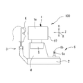
はじめに、図1を参照して、眼科装置100の外観構成を説明する。なお、以下の説明では、図1のX方向を左右方向、Y方向を上下方向、Z方向を前後方向として説明する。
First, an external configuration of the
撮影装置100は、被検眼Eの角膜部位の画像を撮影する装置である。図1に示すように、撮影装置100は、撮影部1(装置本体)と、基台2と、顔支持ユニット3と、移動台4と、を有している。撮影装置100は、いわゆる据え置き型の装置である。撮影装置100の光学系は、撮影部1の筐体1aの中に収容されている。
The
移動台4は、図示なき摺動機構によって、基台2上で移動できる。移動台4には、XYZ駆動部5が設けられている。XYZ駆動部5によって、撮影部1は、被検眼Eに対して左右方向(X方向)、上下方向(Y方向)および前後方向(Z方向)に移動できる。移動台4は、検者がジョイスティック6を傾けて操作することによって、基台2上をXZ方向に移動する。また、検者が回転ノブ6aを回転操作することによって、撮影部1はXYZ駆動部5のY駆動によりY方向に移動される。ジョイスティック6の頂部には、スタートスイッチ56が設けられている。モニタ97は、撮影部1の筐体1aの検者側に設けられている。
The movable table 4 can be moved on the
なお、撮影部1を移動させる構成としては、メカニカルな摺動機構を設けず、駆動部5のモータの駆動によって撮影部1を左右眼に対して移動させる構成であってもよい。また、本装置は、ジョイスティック6のような手動用操作部材としてタッチパネルを有する構成であってもよい。
In addition, as a structure which moves the imaging | photography part 1, the structure which moves the imaging | photography part 1 with respect to a right-and-left eye by the drive of the motor of the
また、本実施形態では、筐体1aにおける被検者側側面とは反対側の面に、モニタ97が設けられている。但し、モニタ97は、筐体1aの他の位置に配置されてもよいし、撮影装置100とは、別体に設けられてもよい。
In the present embodiment, the
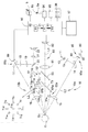
次に、図2を参照して、撮影装置100の光学系および制御系を説明する。なお、図2に示す光学配置は、撮影部1に収容された光学系を上から見たときの配置である。
Next, an optical system and a control system of the photographing
本実施形態の撮影装置100は、角膜撮影光学系10(本実施形態における「第2光学系」)、正面投影光学系50、第1投影光学系60a,60b、第2投影光学系65(65a〜65d)(図3参照)、内部固視光学系70(70a〜70g)、外部固視光学系75(75a〜75f)(図3参照)、および前眼部観察光学系80(本実施形態における「観察光学系」、および、Zアライメント検出光学系85を有する。
The
角膜撮影光学系10は、照明光学系10a(本実施形態における「第2投光光学系」)および受光光学系10b(本実施形態における「第2受光光学系」)を有する。角膜撮影光学系10は、照明光学系10aによって、照明光源11(第1光源)からの光を被検眼Eの角膜Ecに向けて投光する。また、角膜撮影光学系10は、受光光学系10bによって、照明光源11から照射され角膜Ecで反射された反射光を撮像素子22(本実施形態における「第2光検出器」)で受光する。撮影装置100は、角膜撮影光学系10を用いて眼の角膜部位を非接触にて撮影する。
The cornea photographing
照明光学系10aと受光光学系10bの光軸は、例えば、被検眼E上で交差する。照明光学系10aおよび受光光学系10bは、ある中心軸に対して対称に配置されると有利である。本実施形態において、照明光学系10aの光軸L2と受光光学系10bの光軸L3とは、光軸L1に関して左右対称である。
The optical axes of the illumination
本実施形態の照明光学系10aは、照明光源11、集光レンズ12、スリット板13、ダイクロイックミラー14、および投光レンズ15、を有する。照明光源11は、角膜部位の撮影に使用する照明光を出射する。本実施形態において、照明光源11は、可視光を出射する。照明光源11としては、例えば、可視LED、フラッシュランプ等が用いられてもよい。また、ダイクロイックミラー14は、可視光を反射し、赤外光を透過する。スリット板13と角膜Ecは、対物レンズ15に関して略共役な位置に配置されている。照明光源11から出射された光は、集光レンズ12で集光されて、スリット板13に形成されたスリットを通過する。スリット板13を通過したスリット光は、ダイクロイックミラー14で反射された後、投光レンズ15によって収束されることによって、角膜Ecに照射される。
The illumination
受光光学系10bは、内皮細胞を含む角膜Ecからの反射光を撮像素子22によって受光する。本実施形態の受光光学系10bは、対物レンズ16、ダイクロイックミラー17、マスク18、第1結像レンズ19、ミラー20、第2結像レンズ21、二次元撮像素子22(以下、「撮像素子22」と省略する)、を有する。ダイクロイックミラー17は、可視光を反射し、赤外光を透過する。マスク18は、角膜Ecと略共役な位置に配置される。第1結像レンズ19、および第2結像レンズ21は、内皮細胞像を撮像素子22上に結像させる結像光学系を形成する。撮像素子22は、内皮細胞を撮影するために使用される。撮像素子22は、角膜Ecと略共役な位置に配置される。撮像素子22としては、例えば、2次元CCDイメージセンサ(Charge coupled device image sensor)、2次元CMOS(Complementary Metal Oxide Semiconductor Image Sensor)、等が用いられてもよい。
The light receiving
照明光学系10aから角膜Ecに導かれた光は、角膜Ecで反射されることによって、光軸L3方向(斜め方向)に導かれる。その後、光は対物レンズ16、ダイクロイックミラー17を介して、マスク18にて一旦結像される。マスク18は、内皮細胞像を取得する際にノイズとなる光を遮光する。マスク18を通過した光は、第1結像レンズ19、ミラー20、第2結像レンズ21を介して撮像素子22に結像される。その結果、高倍率の内皮細胞像が取得される。
The light guided from the illumination
正面投影光学系50は、正面から角膜Ecに向けてXYアライメント用のアライメント指標を投影する。正面投影光学系50は、赤外光源51、投光レンズ52、およびハーフミラー53、を有する。正面投影光学系50は、赤外光源51の点灯によって、XYアライメント検出用の赤外光を光軸L1方向から角膜Ecに投影する。
The front projection
また、第1投影光学系60a,60bおよび第2投影光学系65a〜65dは、XYZアライメント用のアライメント指標を投影する。撮影装置100では、第1投影光学系60および第2撮影光学系65から投影されるアライメント指標を利用しておおまかなアライメントが行われる。
The first projection
第1投影光学系60a,60bは、斜めから角膜Ecに向けて無限遠のアライメント指標を投影する。第1投影光学系60a,60bは、光軸L1に対して所定の角度でそれぞれ傾斜して配置されている。第1投影光学系60a,60bは、赤外光源61a、61bと、コリメータレンズ63a、63bと、をそれぞれ有し、光軸L1を挟んで左右対称に配置され、眼Eに対して無限遠の指標を投影する(図3参照)。なお、第1投影光学系60a,60bは、光軸L1を通る水平方向と略同一経線上に配置されている(図3参照)。
The first projection
光源61a、61bから出射された光は、コリメータレンズ63a、63bによってそれぞれコリメートされた後、角膜Ecに投影される。その結果、角膜Ec上に指標i20、i30が形成される(図4参照)。
The lights emitted from the
第2投影光学系65a〜65dは、複数の斜め方向から角膜Ecに向けて有限遠のアライメント指標をそれぞれ投影する。第2投影光学系65a〜65dは、光軸L1に対しそれぞれ傾斜して配置されている。第2投影光学系65a〜65dは、赤外光源66a〜66dをそれぞれ有し、光軸L1を挟んで左右対称に配置され、眼Eに対して有限遠の指標を投影する。なお、第2投影光学系65a、65bは、光軸L1に対して上方に配置され、Y方向に関して互いに同じ高さに配置されている。また、第2投影光学系65c、65dは、光軸L1に対して下方に配置され、Y方向に関して互いに同じ高さに配置されている。また、第2投影光学系65a、65bと、第2投影光学系65c、65dは、光軸L1を挟んで上下対称な関係で配置されている。
The second projection
ここで、光源66a、66bからの光は角膜Ecの上部に向けて斜め上方向から照射され、光源66a、66bの虚像である指標i40、i50が形成される。また、光源66c、66dからの光は角膜Ecの下部に向けて斜め下方向から照射され、光源66c、66dの虚像である指標i60、i70が形成される(図4参照)。
Here, the light from the
上記のような指標投影光学系によれば、指標i10は、眼Eの角膜頂点に形成される(図4参照)。また、第1投影光学系60a、60bによる指標i20、i30は、指標i10と同じ水平位置において、指標i10に関し左右対称に形成される。更に、第2投影光学系65a、65bによる指標i40、i50は、指標i10より上方において、指標i10に関し左右対称に形成される。第2投影光学系65c、65dによる指標i60、i70は、指標i10より下方において、指標i10に関し左右対称に形成される。
According to the index projection optical system as described above, the index i10 is formed at the corneal apex of the eye E (see FIG. 4). In addition, the indices i20 and i30 by the first projection
撮影装置100は、固視光学系(例えば、図2の内部固視光学系70および外部固視光学系75)を有している。本実施形態において、それぞれの固視光学系70,75は、光軸と直交する面上に複数配置された固視灯を持ち、点灯位置が切換えられることによって、被検眼の視線方向を変更させる。
The photographing
内部固視光学系70(70a〜70i)は、筐体1aの内部から被検眼Eに対して固視標を投影する。それぞれの内部固視光学系70a〜70iは、可視光源(固視灯)71a〜71iの一つと、投光レンズ72と、ダイクロイックミラー73とを有する。可視光源(固視灯)71a〜71iは、光軸L4に対して直交する方向に関して異なる位置に配置される。なお、ダイクロイックミラー73は、可視光を反射し、赤外光を透過する。光源71から発せられた可視光は、投光レンズ72によって平行光束に変換された後、ダイクロイックミラー73によって反射される。その結果、被検眼Eの眼底に固視標が投影される。例えば、可視光源71aは、光軸L4近傍に配置されている。可視光源71aは、眼Eを正面方向に誘導するために用いられる。可視光源71は、角膜Ecの中心部の内皮画像を得る際に点灯される。また、複数の可視光源71b〜71iは、光軸L4を中心とする同一円周上に配置されている。図2の例では、被検者から見て、0度、45度、90度、135度、180度、225度、270度、315度の各位置に45度ずつ配置されている。可視光源71b〜71iは、眼Eの視線方向を周辺方向に誘導することによって、角膜中心部の周辺における内皮画像を得るために用いられる。
The internal fixation optical system 70 (70a to 70i) projects a fixation target onto the eye E from the inside of the
外部固視光学系75a〜75fは、筐体1aの外部から被検眼Eに対して固視標を投影する。外部固視光学系75a〜75fは、XY方向に関して異なる位置に配置される複数の固視標を有し、被検眼の固視方向を内部固視光学系70より大きく振らせる。外部固視光学系75a〜75fは、筐体1aの外側(つまり、撮影部1の外側)であって、被検眼側に設けられる。例えば、筐体1aの被検眼側筐体面に設けられてもよい。図3に示す外部固視光学系75a〜75fは、可視光源(固視灯)76a〜76fを有し、光軸L1を中心とする同一円周上で、被検者から見て、2時、4時、6時、8時、10、12時の各位置に配置される。可視光源76a〜76fは、被検眼Eの視線方向を周辺方向に誘導することによって、角膜の周辺部における内皮画像を得るために用いられる。この場合、可視光源71b〜71gによって取得される画像より更に外側の内皮細胞像が取得される。
The external fixation
例えば、角膜下部を撮影する場合、固視灯(固視標)の位置が上方に設定され、眼Eの固視が上方向に誘導される。また、角膜上部を撮影する場合、固視灯(固視標)の位置が下方に設定され、眼Eの固視が下方向に誘導される。 For example, when photographing the lower cornea, the position of the fixation lamp (fixation target) is set upward, and fixation of the eye E is guided upward. When photographing the upper cornea, the position of the fixation lamp (fixation target) is set downward, and fixation of the eye E is guided downward.
また、本実施形態では、位置の異なる複数の固視灯を切換えて点灯することによって誘導する視線方向を変更する光学系を用いる場合について説明するが、必ずしもこれに限られるものではなく、例えば、単一の固視灯を光軸と直交する方向に移動する構成を持ち、被検眼Eの視線方向を変更してもよい。また、他の構成としては、固視光学系は、液晶ディスプレイ、有機EL(エレクトロルミネッセンス)などの表示パネルを持ち、発光位置を制御することにより、被検眼Eの視線方向を変更してもよい。 Further, in the present embodiment, a case where an optical system that changes a line-of-sight direction that is guided by switching and lighting a plurality of fixation lamps at different positions is described, but the present invention is not necessarily limited thereto. A single fixation lamp may be configured to move in a direction orthogonal to the optical axis, and the line-of-sight direction of the eye E may be changed. As another configuration, the fixation optical system may have a display panel such as a liquid crystal display or an organic EL (electroluminescence), and change the line-of-sight direction of the eye E by controlling the light emission position. .
前眼部観察光学系80は、前眼部像を正面から観察および撮影するために用いられる。前眼部観察光学系80は、対物レンズ81、および二次元撮像素子82(本実施形態における「光検出器」、以下、「撮像素子82」と省略する)を有する。撮像素子82は、前眼部像およびアライメント指標を撮影する。XY方向のアライメント、およびZ方向のおおまかなアライメントは、撮像素子82によって撮影されるアライメント指標像に基づいて行われる。撮像素子82としては、例えば、2次元CCDイメージセンサ、2次元CMOS等が用いられてもよい。なお、前眼部の撮影に使用する光源としては、図示なき前眼部照明光源が用いられる。
The anterior segment observation
撮像素子82の出力は、後述の制御部90に入力される。図4に示すように、モニタ97には、撮像素子82によって撮像された前眼部像が表示される。なお、モニタ97上に電子的に表示されるレチクルLTは、XYアライメントの基準を示している。なお、前眼部観察光学系80は、被検眼Eに対する撮影部1のアライメント状態を検出するための検出光学系を兼用する。
The output of the
本実施形態において、Zアライメント検出光学系85は、Z方向の精密なアライメントのために利用される。Zアライメント検出光学系85は、投光光学系85aと、検出光学系85bとを有する。本実施形態において、投光光学系85aの光軸L2と検出光学系85bの光軸L3は、光軸L1に関して左右対称な位置に配置される。Zアライメント検出光学系85は、被検眼角膜Ecに対する角膜撮影光学系10のフォーカス状態を検出するための光(つまり、検出光)を、被検眼角膜Ecに向けて斜めから投光する。一方、検出光学系85bは、複数の画素が配列された検出器89(光検出器)を備え、投光光学系85aから投光された光の角膜Ecからの反射光を検出器89によって受光する。
In the present embodiment, the Z alignment detection
本実施形態の投光光学系85aは、照明光源86、集光レンズ87、ピンホール板88、およびレンズ15を有する。ピンホール板88は、角膜Ecと略共役な位置に配置される。本実施形態の検出光学系85bは、レンズ16、および検出器89を有している。検出器89としては、例えば、一次元受光素子(ラインセンサ)が使用されてもよい。検出器89と角膜Ecは、略共役な位置に配置される。光源86から出射された赤外光は、集光レンズ87を介してピンホール板88を照明する。ピンホール板88の開口を通過した光は、レンズ20を介して角膜Ecに投光される。角膜Ecにて光は光軸L3に向けて反射される。その後、角膜反射光は、レンズ16、およびダイクロイックミラー17を介して検出器89よって受光される。検出器89は、角膜反射光の深さ方向の強度分布を、信号として制御部90へ出力する。検出器89からの出力信号は、Z方向のアライメント状態を検出するために利用される。ここで、検出器89上における検出光の受光位置は、Z方向における撮影部1と被検眼Eとの位置関係に応じて変化される。撮影装置100は、検出光の受光位置とアライメント適正位置とのずれを検出することによりZ方向のアライメントずれ量を検出する。
The light projecting
次に、撮影装置100の制御系の概略構成について説明する。
Next, a schematic configuration of the control system of the photographing
撮影装置100は、制御部90によって各部の制御が行われる。制御部90は、駆動部5、ジョイスティック6、各種光源11,71,61,86、撮像素子22,82、検出器89、HDD94、画像処理IC95、操作入力部96、およびモニタ97と接続される。なお、モニタ97は、タッチパネルであってもよい。この場合モニタ97は、操作入力部96の一部を兼用する。
In the photographing
制御部90は、CPU91と、ROM92と、RAM93とを備える。CPU91は、撮影装置100に関する各種の処理を実行するための処理装置である。ROM92は、各種の制御プログラムおよび固定データが格納された不揮発性の記憶装置である。RAM93は、書き換え可能な揮発性の記憶装置として用いられるが、勿論これに限定されない。RAM93には、制御プログラムが実行される際に一時データが格納される。
The
HDD94は、書き換え可能な不揮発性の記憶装置として用いられるが、勿論これに限定されない。本実施形態において、HDD94には、後述するメイン処理のプログラムが記憶される。また、撮影装置100によって撮影された被検眼の画像は、HDD94に記憶される。
The
画像処理IC95は、画像形成部として用いられる。画像処理IC95は、撮像素子22から出力される信号を処理することによって、内皮細胞像の画像(以下、「内皮画像」と称する)を形成する。また、撮像素子82から出力される信号を処理することによって、前眼部正面像の画像(以下、「前眼部画像」と称する)を形成する。本実施形態では、制御部90とは別体の回路である画像処理IC95によって、被検眼に関する画像を形成する等の画像処理が行われるが、必ずしもこれに限られるものではなく、画像処理の一部または全部が制御部90によって行われる構成であってもよい。
The
次に、図5のフローチャートを参照して、撮影装置100における角膜内皮細胞画像の撮影動作を説明する。撮影装置100は、角膜内皮細胞画像を角膜の広範囲において得るために、固視標の呈示位置を切換えながら、内皮細胞画像の撮影を複数回にわたって行う。以下、動作の詳細を説明する。
Next, with reference to the flowchart in FIG. 5, a photographing operation of a corneal endothelial cell image in the photographing
撮影装置100は、まず、前眼部観察光学系80を介して得られる前眼部画像を用いて、被検眼に対する装置のアライメントを行う。
The
アライメントに際して、固視灯の点灯が開始される(S1)。まずは、複数の固視灯71a〜71i,76a〜76fの中で、光軸L4近傍の固視灯71aが点灯される。つまり、光軸L4近傍の呈示位置にて、固視標が被検眼Eに呈示される。この場合において、検者は、固視灯71a(つまり、固視標)を固視するよう被検者に指示する。
At the time of alignment, lighting of the fixation lamp is started (S1). First, among the plurality of
また、CPU91は、図示なき前眼部観察用光源の点灯を開始すると共に、画像処理IC95による前眼部観察画像(ライブ画像)の生成と、モニタ97への出力とを開始させる(S2)。前眼部観察画面200は、被検眼Eに対する撮影部1のアライメントに利用するために形成され、表示される。本実施形態では、画像処理IC95によって逐次形成される前眼部観察画像が、モニタ97における前眼部観察画面200(図4参照)で逐次表示されるようになる。
Further, the
次に、アライメント処理が行われる(S3)。アライメント処理(S3)によって、被検眼Eに対する撮影部1のアライメントが行われる。ここで、本実施形態のアライメント処理によるアライメント動作を説明する。まず、CPU91は、アライメント用の光源を点灯させる。
Next, alignment processing is performed (S3). The alignment of the imaging unit 1 with respect to the eye E is performed by the alignment process (S3). Here, an alignment operation by the alignment process of the present embodiment will be described. First, the
本実施形態では、XY方向のアライメントは、ジョイスティック6の操作に基づく手動によるおおまかなアライメントと、自動アライメントとの2段階で行われる。ジョイスティック6の操作に基づく手動でのアライメントの間、CPU91は、第2投影光学系65a〜65dによって投影される指標像指標i40、i50、i60、i70の検出を行う。指標i40、i50、i60、i70が検出されるようになると、CPU91は、指標i40、i50、i60、i70からなる矩形の中心位置を略角膜頂点として検出する。この矩形の中心位置と、画像中心位置(つまり、前眼部観察光学系の光軸中心位置)との偏位に基づいて、XY方向におけるアライメントずれ方向/偏位量を検出する。CPU91は、アライメントずれが許容範囲に入るように撮影部1をXY方向に移動させる。その結果として、指標像i10が前眼部観察画像から検出されるようになると、CPU91は、指標像i40〜i70によるアライメントを終了し、指標i10を用いたアライメントを行う。指標像i10とアライメント基準位置(例えば、画像中心)に対するずれ量が許容範囲に入るように、CPU91は、撮影部1をXY方向に移動させる。以上のようにして、XY方向のアライメントが行われる。
In the present embodiment, the alignment in the X and Y directions is performed in two steps: a rough manual alignment based on the operation of the
また、本実施形態において、Z方向のアライメントは、第1自動アライメントと、第2自動アライメントとの2段階で行われる。第1自動アライメントは、無限遠の指標像i20、i30と、有限遠の指標像i60、i70との検出結果が用いられる。指標i10が検出されるようになると、無限遠の指標像i20、i30もまた検出される。CPU91は、指標像i20、i30の間隔と有限遠の指標像i60、i70の間隔とを比較することによりZ方向のアライメントずれ方向/偏位量を求める(第1アライメント検出)。また、CPU91は、Z方向のアライメントずれが許容範囲に入るように撮影部1をZ方向に移動させる(第1自動アライメント)。ここでは、撮影部1が作動距離方向にずれた場合に、無限遠指標i20、i30の間隔がほとんど変化しないのに対して、有限遠の指標像i60、i70の像間隔が変化するという特性を利用して、Z方向のアライメントずれを求める(詳しくは、特開平6−46999号参照)。なお、指標像i60、i70の代わりに、指標像i40、i50が利用されてもよい。また、光軸L1からの指標の距離(指標高さ)に基づいてZ方向のアライメント状態が検出されてもよい。
In the present embodiment, the alignment in the Z direction is performed in two stages: a first automatic alignment and a second automatic alignment. In the first automatic alignment, detection results of index images i20 and i30 at infinity and index images i60 and i70 at finite distance are used. When the index i10 is detected, index images i20 and i30 at infinity are also detected. The
第1自動アライメントの完了後、第2自動アライメントが行われる。第2自動アライメントには、Zアライメント検出光学系85a,85bが用いられる。第2自動アライメントの間、CPU91は、光源86を点灯させることによって、投光光学系85aから検出光を角膜Ecに継続して投光する(光源86を予め点灯させていてもよい)。
After the completion of the first automatic alignment, the second automatic alignment is performed. Z alignment detection
検出光の角膜反射光は、検出光学系85bの検出器89にて検出される。CPU91は、検出器89から出力される信号に基づいて駆動部5を制御し、撮影部1をZ方向に移動させる。例えば、CPU91は、深さ方向に関する角膜反射光の強度分布を示す波形において角膜上皮からの反射光に対応するピークPを、検出器89からの出力信号によって示される強度分布に基づいて検出する(図6参照)。検出器89上における上皮ピークの位置Pzが、検出器89の所定画素の位置(例えば、中心の画素の位置)となるように駆動部5を駆動させる。その結果として、撮影装置100では、角膜撮影光学系10のフォーカスが角膜上皮またはその近傍にセットされる。以上のようにして、Z方向のアライメントが行われる。
The cornea reflected light of the detection light is detected by the
本実施形態において、CPU91は、XYZ方向におけるアライメントの完了を検出する。例えば、XY方向のアライメントに関し、CPU91は、指標像i10とアライメント基準位置(例えば、画像中心)に対するずれ量が許容範囲に入ると判定したことを以てアライメント完了を検出する。また、例えば、Z方向のアライメントに関し、CPU91は、上皮ピークの位置Pzが、検出器89の所定画素の位置となったと判定したことを以てアライメント完了を検出する。XYZ方向のアライメント状態の完了が検出された場合、CPU91は、アライメント処理(S4)を終了する。このとき、CPU91は、アライメント用の光源を消灯する。
In the present embodiment, the
アライメントの完了がCPU91によって検出された後、本実施形態では、前眼部観察光学系80を介して得られる前眼部観察画像の静止画を取得(キャプチャー)し、HDD94に記憶する(S4)。
After the completion of the alignment is detected by the
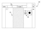
また、アライメントの完了後、CPU91は、角膜撮影光学系10を用いて角膜の観察画像(本実施形態では、ライブ画像)の取得と、モニタ97への表示を開始する(S5)。この場合、例えば、図7に示すように、モニタ97上には、観察画面300が表示される。そして、角膜画像のライブ画像は、角膜観察画面300内のウインドウ301において示される。また、観察画面300上には、固視位置グラフィック304が表示される。固視位置グラフィック304は、被検眼Eから見て点灯されている固視灯71a〜71i,76a〜76fの位置を示す。固視位置グラフィック304によって、検者は、角膜中心周辺における内皮画像の撮影位置を容易に把握できる。なお、第2自動アライメントから引き続き、CPU91は、投光光学系85aから検出光が継続して投光されるように制御する。
Further, after the alignment is completed, the
次に、CPU91は、角膜内皮画像を撮影する(S6)。本実施形態では、まずは、固視灯75aが点灯した状態において、角膜内皮画像が撮影される。角膜内皮画像の撮影は、角膜撮影光学系10のフォーカスが角膜内皮に調整された後に行われる。より詳細には、検出器89から出力される信号に基づいて駆動部5の駆動を制御することによって、角膜撮影光学系10のフォーカスを角膜内皮に自動的に調節する。そして、CPU91は、内皮画像を撮影する。制御部90は、照明光源12を発光させる。そして、撮像素子22によって、少なくとも1つの内皮画像を取得し、取得された内皮画像をメモリ92に記憶する(オートショット)。複数の内皮画像を取得する場合、制御部90は、駆動部5の駆動を制御して、撮影部1aを所定方向に移動させる。そして、撮影部1aの移動中に照明光源11を連続発光させることによって、撮像素子22で複数の内皮画像を取得してもよい。なお、この場合において、制御部90は、オートアライメント、或いはオートトラッキングを行ってもよい(詳細については、例えば、特開2013−212217号公報等を参照されたい)。
Next, the
次に、CPU91は、固視灯71a〜71i,76a〜76fの中から、点灯させる固視灯を変更する(S7)。これによって、本実施形態では、被検眼に提示される固視標の呈示位置が、第1呈示位置から、第1呈示位置とは異なる第2呈示位置へと、点灯切換信号に基づいて切換えられる。なお、第1呈示位置は、2回続けて角膜内皮細胞画像の撮影が行われる場合において、先の撮影における固視標の呈示位置であり、第2呈示位置は、後の撮影における固視標の呈示位置である。本実施形態におけるS7の処理では、予め定められた固視灯の点灯順序に従って、点灯する固視灯が切換えられる。ここでは、点灯順序の一例として、71a⇒71b⇒71c⇒・・・(中略)⇒71i⇒76a⇒76b⇒・・・(中略)⇒76fの順に切換えられるものとする。この点灯順序によれば、例えば、固視灯71aの点灯後は、固視灯71bが点灯する状態に切換えられる。つまり、固視標の呈示位置は、L4近傍の呈示位置から、L4に対して右側となるL4周辺の呈示位置へと切換えられる。ここでは、ある呈示位置において固視標が呈示される場合、その呈示位置に対応する固視灯は、点灯する状態が継続的に維持される状態(いわゆる常時点灯)であるものとする。但し、これに限られるものではなく、固視灯において点灯と消灯を繰り返す(つまり、点滅する)ことによって、固視標が呈示されてもよい。
Next, the
なお、それぞれの固視灯の点灯順序(つまり、固視標の呈示順序)は、必ずしも一義的に定められる必要はない。複数パターン用意されていてもよい。この場合、検者が撮影の目的に応じて、点灯順序を選択可能な構成であってもよい。また、撮影前または撮影時において、検者が点灯順序を任意に設定可能な構成であってもよい。 Note that the lighting order of each fixation lamp (that is, the fixation target presentation order) does not necessarily have to be uniquely determined. A plurality of patterns may be prepared. In this case, a configuration in which the examiner can select the lighting order according to the purpose of photographing is also possible. Further, a configuration in which the examiner can arbitrarily set the lighting order before or at the time of photographing may be employed.
固視灯の呈示位置が変更された後、CPU91は、前述のS4と同様に、前眼部観察光学系80を介して得られる前眼部観察画像の静止画を取得(より詳細には、キャプチャーし、HDD94に記憶)する(S8)。
After the fixation lamp presentation position is changed, the
そして、CPU91は、固視標の呈示位置が切換えられる前後において(つまり、固視灯の呈示位置を切換えるための点灯切換信号の出力の前と、後と、において)取得された2枚の前眼部画像から、視線方向情報を検出する(S9)。つまり、固視標の呈示位置が第1呈示位置である場合に得られる前眼部画像(第1観察画像)から、第1視線方向情報を取得し、更に、固視標の呈示位置が第2呈示位置である場合に得られる前眼部画像(第2観察画像)から第2視線方向情報を取得する。このように、本実施形態では、それぞれの前眼部画像から、視線方向情報がそれぞれ検出される。視線方向情報は、被検眼の視線方向に関する情報である。S9の処理では、被検眼Eの視線方向が異なると、視線方向情報として異なる情報が検出される。前眼部画像から得られる視線方向情報としては、種々の情報を利用しうる。ここでは、具体例として、被検眼の瞳孔の位置と角膜輝点spの位置とが利用されるものとする(図8参照)。角膜輝点spは、例えば、前眼部観察光学系50からの前眼部照明(図示せず)が角膜Ecに照射されることによって、角膜頂点、或いはその近傍に形成される。
The
図8(a)は、被検眼Eの視線が光軸L4に近傍に配置された固視標(固視灯71a)を向いているときの前眼部画像を示し、図8(b)は、図8(b)に対して正面視左下を向いているときの前眼部画像を示す。このように、視線方向に応じて角膜輝点spが生じる位置は、瞳孔に対して変化するので、被検眼Eの瞳孔の位置(例えば、瞳孔中心icの位置)と角膜輝点spの位置とから、おおよその視線方向を得ることができる。このような具体例において、CPU91は、それぞれの前眼部画像を画像処理することによって、瞳孔中心位置と,角膜輝点位置と,をそれぞれの前眼部画像から検出する。そして、それぞれの前眼部画像から検出される視線方向情報として、例えば、それぞれの前眼部画像における瞳孔中心icの位置を基準とした角膜輝点spの位置情報を取得する。
FIG. 8A shows an anterior eye image when the line of sight of the eye E faces a fixation target (
次に、CPU91は、固視標の呈示位置が切換えられた場合に、固視標の呈示位置の切換えに伴い被検眼の視線方向が変化したか否かを判定する(S10)。この判定は、固視標の呈示位置が切換わる前後での視線方向情報の変化量(つまり、第1視線方向情報と第2視線方向情報との差分)に基づいて行われる。視線方向情報の変化量が少ない場合は、呈示位置が切換えられた後の固視標に対して被検者の固視が適正に行われている可能性が少ないと考えられる。
Next, when the fixation target presentation position is switched, the
S10の判定では、より具体的には、CPU91は、視線方向情報の変化量を、ある閾値と比較して、変化量と閾値との大小関係に応じた判定結果を出力する。ここで、視線方向情報の変化量は、例えば、上記の第1観察画像と,第2観察画像と,における瞳孔中心icを基準とした角膜輝点spの位置の変化量であってもよい。
More specifically, in the determination of S10, the
また、閾値は、固視微動による視線方向情報の変化量であって、通常の被検眼において想定される変化量に対して、大きな値が設定される。なお、角膜輝点spの位置の変化量を視線方向情報の変化量として用いる具体例においては、閾値は、固視微動に伴う角膜輝点spの位置の変化量に対して大きな値に設定される。 Further, the threshold is a change amount of the gaze direction information due to the fixation fine movement, and a large value is set with respect to the change amount assumed in the normal eye to be examined. In the specific example in which the amount of change in the position of the corneal luminescent spot sp is used as the amount of change in the line-of-sight direction information, the threshold value is set to a large value with respect to the amount of change in the position of the corneal luminescent spot sp associated with the fixation eye movement. The
ここで、閾値は、固視微動の中で振幅の最も大きな運動であるフリック(マイクロサッカード)による視角の変化に対して大きな値が設定されてもよい。フリックの大きさについては諸説あるが、おおよそ1°以内といわれている。このため、例えば、閾値を1°以上とすれば、固視微動による視線の変化と、固視微動以外の視線方向の変化とを良好に区別できると考えられる。尚、閾値は、固視標の呈示位置同士の間隔に対して、小さな値に設定される必要がある。例えば、固視標の呈示位置同士の間隔が、最も狭い箇所で5°程度である場合には、例えば、2°から4°程度の間に、閾値が設定されてもよい。 Here, the threshold value may be set to a large value with respect to a change in the viewing angle caused by flicking (microsaccade), which is the movement with the largest amplitude in the fixation fine movement. There are various theories about the size of the flick, but it is said that it is within 1 °. For this reason, for example, if the threshold is set to 1 ° or more, it is considered that a change in the line of sight due to fine fixation movement and a change in the line of sight direction other than the fixation fine movement can be distinguished well. The threshold value needs to be set to a small value with respect to the interval between the fixation target presentation positions. For example, when the interval between the fixation target presentation positions is about 5 ° at the narrowest portion, for example, a threshold value may be set between about 2 ° and 4 °.
本実施形態において、S10の判定では、第1観察画像と第2観察画像とにおける視線方向情報の変化量が、閾値よりも大きな場合は、被検眼の視線方向が変化したと判定される(S10:Yes)。一方、視線方向情報の変化量が、閾値よりも小さな場合は、被検眼の視線方向が変化していないと判定される(S10:No)。 In the present embodiment, in the determination of S10, when the amount of change in the line-of-sight direction information between the first observation image and the second observation image is larger than the threshold value, it is determined that the line-of-sight direction of the eye to be examined has changed (S10). : Yes). On the other hand, when the amount of change in the line-of-sight direction information is smaller than the threshold value, it is determined that the line-of-sight direction of the eye to be examined has not changed (S10: No).
なお、S10の判定に加え、第1観察画像と、第2観察画像との間における視線方向情報の変化が(例えば、瞳孔中心icを基準とした角膜輝点spの移動ベクトルの向きが)、固視標の呈示位置の変更に応じた方向への変化であるか否かを更にCPU91が判定するようにしてもよい。例えば、第1の呈示位置に対して第2の呈示位置が上方になる場合において、視線方向情報の変化が、視線方向の上方への変化を示すものであるか否かを、視線方向情報の変化に基づいて(具体例としては、瞳孔中心icを基準とした角膜輝点spの移動ベクトルの符号に基づいて)判定するようにしてもよい。固視標の呈示位置の変更に応じた方向へ視線方向が変化していなければ、呈示位置が切換えられた後の固視標に対して被検者の固視が適正に行われていないと考えられる。よって、この場合、CPU91は、上記のS10の処理において、No判定となった場合と同様のステップに進んでもよい。また、固視標の呈示位置の変更に応じた方向へ視線方向が変化していると判定されれば、上記のS10の処理において、Yes判定となった場合と同様のステップに進んでもよい。
In addition to the determination in S10, a change in the line-of-sight direction information between the first observation image and the second observation image (for example, the direction of the movement vector of the corneal bright spot sp with respect to the pupil center ic) The
S10の処理によって、被検眼の視線方向が変化していないと判定される場合は(S10:No)、CPU91は、固視不良のおそれがあることを示す情報を情報提供部から出力させる(S11)。一例として、本実施形態において、情報提供部にはモニタ97が利用される。例えば、CPU91は、モニタ97において「固視不良のおそれあり」等のメッセージを表示させることによって、固視不良のおそれがある旨を検者に報知する。結果、メッセージを確認した検者は、被検者に対して、固視ができているか否かを問い合わせたり、固視を促すような指示を行うことが可能となる。
When it is determined that the line-of-sight direction of the eye to be examined is not changed by the process of S10 (S10: No), the
メッセージの表示後、CPU91は、S8の処理に戻って、新たに前眼部画像を取得すると共に、視線方向情報を検出する(S8,S9)。CPU91は、この視線方向情報を、第2視線方向情報として新たに設定したうえで、従前と同じ第1視線方向情報と新たな第2視線方向情報との変化量に基づいて、被検眼の視線方向の変化を再び判定する(S10)。よって、被検者の視線方向が閾値を超えて変化するまで、撮影動作は待機される(例えば、後述するような第2呈示位置での角膜内皮細胞画像の撮影は待機される)。なお、操作入力部96に対する所定の入力操作に応じて、撮影動作の待機が解除されるようにしてもよい。
After displaying the message, the
一方、S10の処理によって、被検眼Eの視線方向が変化したと判定される場合は(S10:Yes)、CPU91は、被検眼Eに対する撮影部1のアライメントを再び実行し(S11)、更にその後、第2呈示位置での角膜内皮画像の撮影を行う(S12)。
On the other hand, when it is determined that the line-of-sight direction of the eye E has changed by the process of S10 (S10: Yes), the
それまでに第1呈示位置での内皮細胞撮影が行われたことによって、撮影部1が内皮側に移動されている。また、被検眼Eにおいても、視線方向が変化したことによって角膜の表面となる位置が変化している。そこで、改めて、被検眼Eと角膜撮影光学系10とが所定の位置関係となるように(例えば、角膜撮影光学系10のフォーカスが角膜頂点位置にセットされる位置関係となるように)、アライメントを行う。ここでのアライメントは、前述のアライメント処理(S3)における全部または一部の動作によって行われるようにしてもよい。
Since the endothelial cell imaging at the first presentation position has been performed so far, the imaging unit 1 has been moved to the endothelial side. Also, in the eye E, the position that becomes the surface of the cornea changes due to the change of the line-of-sight direction. Therefore, the alignment is performed again so that the eye E and the corneal imaging
そして、アライメントの完了がCPU91によって検出された後に、固視標の呈示位置が第2呈示位置である場合における内皮細胞画像の撮影が行われる(S12)。具体的な撮影動作は、S6のときと同様に行われる。CPU91は、撮影した内皮細胞画像をHDD94に記憶する。
Then, after completion of the alignment is detected by the
次に、CPU91は、それぞれの固視標の呈示位置において、内皮細胞の撮影が完了したか否かを判定する(S13)。撮影していない固視標の呈示位置が残っている場合は、S7の処理に戻って、固視灯の点灯位置を更に切換えて、処理を繰り返す。つまり、S7からS13までの処理が新たに実行される。この場合、新たに(つまり、今回)実行されるS7の処理で点灯される固視灯(固視標)の呈示位置が、第2の呈示位置とされる。また、前回(今回に対して1回前)のS7の処理によって点灯された固視灯の呈示位置が、第1の呈示位置とされる。よって、S10の処理では、今回の呈示位置において得た前眼部画像の静止画と、前回の呈示位置において得た前眼部画像の静止画とを比較することによって、被検眼の視線方向が変化したか否かが判定される。
Next, the
一方、それぞれの固視標の呈示位置における撮影が完了した場合は(S13:Yes)、本処理を終了する。 On the other hand, when the photographing at each fixation target presenting position is completed (S13: Yes), this process ends.
ここで、被検眼における各部の形状、および屈折には、個人差があるので、被検眼の視線方向を簡単かつ正確に検出することは難しい。このため、例えば、固視標の呈示方向に対する視線方向の一致度を測定し、測定結果に基づいて被検眼の固視状態を把握することは容易ではない。 Here, since there are individual differences in the shape and refraction of each part in the eye to be examined, it is difficult to easily and accurately detect the line-of-sight direction of the eye to be examined. For this reason, for example, it is not easy to measure the degree of coincidence of the gaze direction with the direction of the fixation target and grasp the fixation state of the eye to be inspected based on the measurement result.
これに対し、本実施形態の眼科装置100は、固視標の呈示位置の切換えに伴い被検眼Eの視線方向が変化したか否かを、固視標の呈示位置が切換わる前後での視線方向情報の変化に基づいて判定する。これによれば、たとえ各固視標の呈示位置間隔が小さな場合であっても、被検眼の固視が切換わっていれば、視線方向情報は固視標の呈示位置の切換えに伴って変化する。よって、少なくとも固視標の呈示位置の切換えに伴って被検眼の視線が移動したことについては、精度良く検出することができる。従って、眼科装置100によれば、被検眼の固視状態を、簡単かつ良好に監視できる。
On the other hand, the
また、本実施形態では、固視標の呈示位置が切換えられた前後における視線方向情報との変化量と、所定の閾値との大小関係に応じて、視線方向が変化したか否かの判定がなされる。閾値は、固視微動による視線方向の変化量に対して大きな値に設定されている。このような閾値は、例えば、視角にして数度程度(例えば、視角5°程度)の視線方向の変化を表す変化量に対して、十分に小さく設定し得る。従って、隣り合う呈示位置の間隔が、視角にして数度程度であったとしても、被検眼の固視状態を、良好に監視し得る。 In the present embodiment, whether or not the gaze direction has changed is determined according to the magnitude relationship between the change amount of the gaze direction information before and after the fixation target presentation position is switched and the predetermined threshold value. Made. The threshold value is set to a large value with respect to the amount of change in the line-of-sight direction due to microscopic fixation. Such a threshold value can be set sufficiently small, for example, with respect to a change amount representing a change in the line-of-sight direction of about several degrees (for example, a viewing angle of about 5 °). Therefore, even if the interval between adjacent presentation positions is about several degrees in view angle, the fixation state of the eye to be examined can be monitored well.
また、固視標の呈示位置を切換える前後で被検眼の視線方向が変化していないと判定される場合には、固視不良のおそれがあることを示すメッセージが、モニタ97から出力される。その結果、上記実施形態では、固視不良のおそれがあることを検者が把握して、検者に固視を促す指示等を行うことができるようになる。よって、撮影装置100では、固視が確実に行われた状態で内皮細胞画像の撮影が行われやすい。
Further, when it is determined that the gaze direction of the eye to be examined has not changed before and after the fixation target presentation position is switched, a message indicating that there is a possibility of fixation failure is output from the
また、本実施形態では、上記判定によって、視線方向が変化したと判定されてから、少なくとも角膜内皮細胞画像の撮影を含むその後の撮影動作(つまり、アライメント動作、および照明光源11の発光動作の少なくともいずれか)が行われる。よって、固視が確実に行われてから撮影動作が行われやすいので、固視不良を原因とする撮影のやり直しが抑制されやすい。また、上記実施形態では、上記の判定において、視線方向が変化したと判定されてから、そのときの固視標の呈示位置でのアライメントが行われる。よって、アライメントのやり直しも抑制される。結果として、撮影装置100によれば、一連の撮影時間を抑制できる。
In the present embodiment, since it is determined that the line-of-sight direction has changed by the above determination, at least a subsequent imaging operation including imaging of a corneal endothelial cell image (that is, an alignment operation and a light emission operation of the illumination light source 11). Any). Therefore, since the photographing operation is easily performed after the fixation is surely performed, it is easy to suppress re-taking of the photographing due to the fixation failure. Moreover, in the said embodiment, after determining with the said determination that the gaze direction changed, alignment in the presentation position of the fixation target at that time is performed. Therefore, re-alignment is also suppressed. As a result, according to the
以上、実施形態に基づいて説明を行ったが、上記実施形態によって開示された技術を、次のように変形しても良い。 As described above, the description has been given based on the embodiment, but the technology disclosed by the above embodiment may be modified as follows.
例えば、上記実施形態において、固視標の呈示位置の切換に伴う視線方向の変化が判定される際には、切換前に得られた前眼部画像(観察画像)と、切換後に得られた前眼部画像とが1枚ずつ使用された。詳細には、CPU91によって、2枚の前眼部画像から視線方向情報の変化が検出された。固視標の呈示位置の切換前(つまり、第1の呈示位置)、或いは、切換後(つまり、第2の呈示位置)における視線方向情報を得るために、それぞれ複数枚の前眼部画像が使用されてもよい。例えば、撮影装置1は、(主には、CPU91によって)固視標が第1の呈示位置であるときに得られる複数枚の前眼部画像における平均的な視線方向情報を取得すると共に、固視標が第2の呈示位置であるときに得られる複数枚の前眼部画像における平均的な視線方向情報を取得し、平均的な視線方向情報同士の変化を検出してもよい。平均的な視線方向情報は、例えば、一定期間で連続して得られる複数枚の前眼部画像から、視線方向情報を画像毎に求め、更に、求めた視線方向情報の平均をとることで、取得してもよい。視線方向情報が平均化されることで、マイクロサッカード等の固視微動による一時的な視線方向の移動の影響が抑制されやすくなる。従って、より良好に被検眼の固視状態を監視できる。
For example, in the above embodiment, when a change in the line-of-sight direction accompanying switching of the fixation target presentation position is determined, the anterior segment image (observation image) obtained before switching and obtained after switching are obtained. One anterior segment image was used. Specifically, the
また、上記実施形態において、視線方向情報は、前眼部画像(観察画像)における瞳孔中心icを基準とする角膜輝点spとの位置情報として検出される場合について説明した。 In the above-described embodiment, the case has been described in which the line-of-sight direction information is detected as position information with respect to the corneal bright spot sp with the pupil center ic as a reference in the anterior segment image (observation image).
特に、上記実施形態では、角膜輝点spとして、角膜頂点に形成される輝点が使用された。しかし、視線方向情報を得るために用いる輝点は、アライメント用の輝点(例えば、図4におけるi20~i70の少なくとも何れか)等、角膜の頂点から離れて形成される輝点であってもよい。 In particular, in the above-described embodiment, the bright spot formed at the apex of the cornea is used as the cornea bright spot sp. However, the bright spot used to obtain the line-of-sight direction information may be a bright spot formed away from the top of the cornea, such as a bright spot for alignment (for example, at least one of i20 to i70 in FIG. 4). Good.
また、視線方向情報は、被検眼Eの視線に関する情報であればよく、必ずしも角膜輝点に基づいて求められた値でなくてもよい。例えば、前眼部画像から視線方向情報を検出する場合であれば、瞳孔形状(或いは角膜形状)を楕円近似した場合における楕円の長軸aと短軸bとの比、および、各軸の角度等を視線方向情報として用いることができる(図9参照)。この場合、装置の正面方向(例えば、光軸L4)に対する視線の傾きが大きい場合ほど、楕円の長軸aは、短軸bに対して長くなる。従って、例えば、閾値を、短軸bに対する長軸aの割合として設定した場合であれば、前眼部画像で検出される楕円における短軸bに対する長軸aの割合の値が、閾値よりも小さい値である場合に、被検眼の視線方向が変化していないものと判定できる。また、上記実施形態では、瞳孔と角膜輝点との位置関係、瞳孔形状等を、制御部70が前眼部画像毎に計算によって求め、その値の比較に基づいて視線方向の変化の有無を判定している。しかし、視線方向の変化を判定する手法は、必ずしもこれに限られるものではない。例えば、制御部70は、観察画像同士の相関を画像マッチング等で求め、その相関に基づいて視線方向の変化を判定してもよい。
The line-of-sight direction information may be information regarding the line of sight of the eye E, and may not necessarily be a value obtained based on the corneal bright spot. For example, in the case of detecting gaze direction information from the anterior ocular segment image, the ratio between the major axis a and the minor axis b of the ellipse when the pupil shape (or corneal shape) is approximated to an ellipse, and the angle of each axis Etc. can be used as line-of-sight direction information (see FIG. 9). In this case, as the inclination of the line of sight with respect to the front direction of the apparatus (for example, the optical axis L4) increases, the long axis a of the ellipse becomes longer than the short axis b. Therefore, for example, if the threshold is set as a ratio of the major axis a to the minor axis b, the value of the ratio of the major axis a to the minor axis b in the ellipse detected in the anterior segment image is greater than the threshold. When the value is small, it can be determined that the line-of-sight direction of the eye to be examined has not changed. In the above embodiment, the positional relationship between the pupil and the corneal bright spot, the pupil shape, and the like are calculated by the
また、上記実施形態では、被検眼Eの固視の状態に関する情報を検者および被検者の少なくとも一方に提供するために、情報提供部としてモニタ97を用いる場合を説明した。但し、モニタ97に表示される情報を用いた情報提供に限られるものではなく、種々の手段を利用し得る。例えば、固視標、およびスピーカー(図示せず)等の何れかを利用してもよい。例えば、固視不良のおそれがある旨を示す情報を、固視標を用いて報知する場合には、その際に被検眼に呈示されている固視標の呈示態様を、通常の状態から変化させるようにしてもよい。例えば、そのときの呈示位置に対応する固視灯の点灯状態を切換えることによって、固視不良のおそれがある旨を、被検者に対して報知してもよい。この場合、例えば、点灯状態は、常時点灯と、点滅との間で切り替えられてもよい。このように、固視標の呈示態様が切換わることによって、被検者の注意を固視標に引きつけ、更には、固視を促すことができると考えられる。また、例えば、固視不良のおそれがある旨を示すメッセージを図示なきスピーカーから音声などによって検者および被検者に報知するようにしてもよい。また、モニタ97とスピーカーの組合せ等、複数の手段が併用されて固視不良のおそれがある旨を示す情報を、検者又は被検者の少なくとも一方に報知してもよい。
Moreover, in the said embodiment, in order to provide the information regarding the fixation state of the eye E to at least one of the examiner and the examinee, the case where the
本実施形態において、撮影装置100は、内部固視灯と外部固視灯とを備えていたが、何れか一方のみを備える構成であってもよい。また、各固視灯は、複数の固視灯の中から点灯させるものを切換えることで、被検眼に対する固視標の呈示位置を切換える構成であったが、必ずしもこれに限られるものではなく、固視灯を、光軸L4と交差する方向に移動させることによって、固視標の呈示位置を切換える構成であってもよい。
In the present embodiment, the
また、上記実施形態の撮影装置100において、固視標の呈示位置が第1呈示位置から第2呈示位置へと切換えられる場合に、第2呈示位置への固視の誘導を促すために、固視標の呈示態様を切換える制御が、CPU91によって行われてもよい。呈示態様の切換は、例えば、第2呈示位置における固視標の色、明滅状態等の切換等がありうる。例えば、固視標の色の切換制御では、固視標の呈示位置が第2呈示位置へと切り替えられた後、一定期間、固視標の色を、撮影時とは異なる色で点灯させてもよい。また、固視標の明滅状態の切換制御は、固視標の呈示位置が第1呈示位置から第2呈示位置へ切り替えられる際に、一定時間、固視灯を消灯し、その後に、第2呈示位置で固視標を呈示するものであってもよい。また、固視標の呈示位置が第2呈示位置へと切り替えられた後、一定期間、第2の呈示位置における固視標を点滅させるものであってもよい。
Further, in the
また、上記実施形態の撮影装置100において、固視標の呈示位置が第1呈示位置から第2呈示位置へと切換えられる場合において、第3呈示位置を中継してもよい。即ち、第1呈示位置から第3呈示位置へと切換えられた後、更に、第3呈示位置から第2呈示位置へと切り替える制御が行われてもよい。この場合において、第3呈示位置は、それぞれの固視標の呈示位置同士の間隔のうち最も狭い間隔に比べて大きな間隔が、第3呈示位置と第2呈示位置との間で確保されるように設定された位置であってもよい。或いは、第3呈示位置は、第1呈示位置と第2呈示位置との間隔に比べて大きな間隔が、第3呈示位置と第2呈示位置との間で確保されるように設定された位置であってもよい。このように、第3呈示位置を経由することで、固視標の呈示位置を大きく移動させることができ、被検者による視線方向の移動が行われやすくなる場合がある。なお、この場合、第1呈示位置である場合に検出される視線方向情報と、第2呈示位置である場合に検出される視線方向情報との変化に基づいて、被検者の固視状態がCPU91によって監視されてもよい。また、第3呈示位置である場合に検出される視線方向情報と、第2呈示位置である場合に検出される視線方向情報との変化に基づいて、被検者の固視状態がCPU91によって監視されてもよい。
In the
上記実施形態では、それぞれの固視標の呈示位置において、角膜内皮細胞画像の撮影が実行される場合は(S6,S12)、検出器89からの出力信号に基づいて、撮影装置100が自動的にフォーカスを合わせて撮影を行うものとして説明した。しかし、必ずしもこれに限られるものではなく、フォーカス調整は、検者によって手動で行われても良い。
In the above-described embodiment, when imaging of a corneal endothelial cell image is executed at each fixation target presentation position (S6, S12), the
また、上記実施形態では、眼科装置の一例として、角膜内皮細胞撮影装置を例示して説明を行ったが、本開示の技術は、被検眼の観察又は撮影を行うための他の眼科撮影装置に適用することができる。例えば、シャインプルークカメラ等の前眼部を撮影(例えば、発光により撮影)する機能を持つ装置に対して適用できるし、眼底カメラ、および、共焦点レーザー検眼鏡等の眼底を撮影(例えば、発光により撮影)する機能を持つ装置に対しても適用できる。勿論、スリットランプおよび手術顕微鏡等の前眼部および眼底の両方を観察等するための装置に対しても適用できる。なお、眼底の画像を撮影する撮影装置では、観察画像として眼底画像を用いることができる。この場合において、撮影装置には、光源から出射される光を被検眼の眼底に向けて投光すると共に、光の眼底反射光を光検出器で受光する観察光学系の他に、更に、光検出器からの受光信号に基づいて眼底正面画像を形成する観察画像形成部(例えば、画像処理IC等)が少なくとも設けられる。また、この場合、観察画像形成部において形成される眼底の観察画像から、視線位置情報が検出されてもよい。この場合、観察画像としては、視線の方向に応じた撮影位置の画像が得られる。そこで、視線位置情報として、観察画像の取得位置に関する情報(例えば、眼底画像における黄斑等の特徴点の位置情報、或いは、眼底画像の画像情報そのもの)を利用し得る。また、視線位置情報の変化量は、画像同士のズレ情報として得ることができる。但し、眼底の画像を撮影する撮影装置において、観察画像として前眼部画像を取得する前眼部観察光学系が更に設けられているのであれば、前眼部画像から視線方向情報を検出してもよい。 In the above embodiment, a corneal endothelial cell imaging device has been described as an example of an ophthalmic device. However, the technique of the present disclosure is applied to other ophthalmic imaging devices for observing or imaging an eye to be examined. Can be applied. For example, the present invention can be applied to an apparatus having a function of photographing an anterior eye portion such as a Shine proof camera (for example, photographing by light emission), and photographing a fundus such as a fundus camera and a confocal laser ophthalmoscope (for example, emitting light). The present invention can also be applied to an apparatus having a function of photographing). Of course, the present invention can also be applied to an apparatus for observing both the anterior segment and the fundus, such as a slit lamp and a surgical microscope. Note that a fundus image can be used as an observation image in an imaging apparatus that captures a fundus image. In this case, in addition to the observation optical system in which the light emitted from the light source is projected toward the fundus of the eye to be examined and the fundus reflected light of the light is received by the photodetector, the imaging apparatus further includes a light An observation image forming unit (for example, an image processing IC or the like) that forms a fundus front image based on a light reception signal from the detector is provided. In this case, the line-of-sight position information may be detected from the fundus observation image formed in the observation image forming unit. In this case, an image at a shooting position corresponding to the direction of the line of sight is obtained as the observation image. Therefore, as the line-of-sight position information, information related to the observation image acquisition position (for example, position information of feature points such as macula in the fundus image or image information of the fundus image itself) can be used. Further, the amount of change in the line-of-sight position information can be obtained as information on the displacement between images. However, in an imaging device that captures an image of the fundus, if an anterior ocular segment observation optical system that acquires an anterior ocular segment image as an observation image is further provided, gaze direction information is detected from the anterior ocular segment image. Also good.
また、本開示の技術は、眼科撮影装置の他に、被検眼の検査に用いる眼科装置(つまり、検眼装置)に適用することができる。例えば、視野計、眼軸長測定装置、自覚検眼装置等の各種の検眼装置に対して適用し得る。 Further, the technology of the present disclosure can be applied to an ophthalmologic apparatus (that is, an optometry apparatus) used for examining an eye to be examined in addition to the ophthalmologic photographing apparatus. For example, the present invention can be applied to various optometry apparatuses such as a perimeter, an axial length measuring apparatus, and a subjective optometry apparatus.
5 駆動機構
10 角膜撮影光学系
10a 照明光学系
10b 受光光学系
22 撮像素子
51 正面投影光学系
70 内部固視光学系
71a〜71i 固視灯
75 外部固視光学系
76a〜76f 固視灯
80 前眼部観察光学系
90 制御部
91 CPU
97 モニタ
E 被検眼
5
97 Monitor E Eye to be examined
Claims (9)
前記被検眼の視線方向に関する情報である視線方向情報を検出する視線方向情報検出手段と、
前記固視標の呈示位置が第1呈示位置から前記第1呈示位置とは異なる第2呈示位置へと切換えられる場合に、前記固視標の呈示位置の切換に伴い前記被検眼の視線方向が変化したか否かを、前記固視標の呈示位置が切換わる前後での前記視線方向情報の変化に基づいて判定する判定手段と、を備えることを特徴とする眼科装置。 A fixation optical system having a fixation target presented to the eye to be examined and capable of switching a presentation position of the fixation target in order to change a visual line direction of the eye to be examined;
Gaze direction information detecting means for detecting gaze direction information which is information relating to the gaze direction of the eye to be examined;
When the fixation target presentation position is switched from the first presentation position to a second presentation position different from the first presentation position, the line-of-sight direction of the eye to be inspected is changed according to the switching of the fixation target presentation position. An ophthalmologic apparatus comprising: a determination unit that determines whether or not a change has occurred based on a change in the gaze direction information before and after the presenting position of the fixation target is switched.
被検眼の固視の状態に関する情報を検者および被検者の少なくとも一方に提供するための情報提供部から、前記第2呈示位置で固視不良のおそれがあることを示す情報を出力させる出力制御手段と、を備えることを特徴とする請求項1記載の眼科装置。 When the determination means determines that the gaze direction of the eye to be examined has not changed before and after the presentation position of the fixation target is switched,
Output that outputs information indicating that there is a risk of fixation failure at the second presentation position from an information providing unit for providing information on the fixation state of the eye to at least one of the examiner and the subject. The ophthalmologic apparatus according to claim 1, further comprising a control unit.
アライメントに使用される観察画像を取得するための観察光学系であって、光源から出射される光を被検眼に向けて照射し、前記光が照射された被検眼の部位からの反射光を光検出器で受光する観察光学系と、
前記光検出器からの受光信号に基づいて被検眼の観察画像を形成する観察画像形成手段と、
前記観察画像形成手段によって形成される前記観察画像に基づいて視線方向情報を取得する情報取得手段と、を備え、
前記情報取得手段は、前記固視標の呈示位置が前記第1呈示位置である場合に得られる前記観察画像である第1観察画像から,第1視線方向情報を取得し、更に、前記固視標の呈示位置が前記第2呈示位置である場合に得られる観察画像である第2観察画像から,第2視線方向情報を取得し、
前記判定手段は、前記第1視線方向情報と前記第2視線方向情報とによって定められる視線方向情報に関する変化量を求め、前記固視標の呈示位置の切換に伴い前記被検眼の視線方向が変化したか否かを、前記変化量に基づいて判定することを特徴とする請求項1又は2記載の眼科装置。 The line-of-sight direction information detecting means includes
An observation optical system for acquiring an observation image used for alignment, irradiating light to be examined from a light source toward the subject's eye, and light reflected from a portion of the subject's eye irradiated with the light An observation optical system that receives light with a detector;
An observation image forming means for forming an observation image of the eye to be inspected based on a light reception signal from the photodetector;
Information acquisition means for acquiring gaze direction information based on the observation image formed by the observation image forming means,
The information acquisition means acquires first gaze direction information from a first observation image that is the observation image obtained when the fixation position of the fixation target is the first presentation position, and further, the fixation Obtaining second gaze direction information from a second observation image, which is an observation image obtained when the target presentation position is the second presentation position;
The determination means obtains a change amount related to the gaze direction information determined by the first gaze direction information and the second gaze direction information, and the gaze direction of the eye to be changed changes with the switching of the presentation position of the fixation target. The ophthalmologic apparatus according to claim 1, wherein it is determined based on the amount of change.
前記観察画像形成手段は、前記観察画像として前眼部正面画像を形成し、
前記情報取得手段は、前眼部正面画像における瞳孔および角膜の少なくとも何れかの部位の情報から視線方向情報を取得することを特徴とする請求項3又は4に記載の眼科装置。 The observation optical system projects light from the light source toward the anterior ocular segment of the subject's eye, and receives the anterior ocular segment reflected light by the light using the photodetector.
The observation image forming means forms an anterior ocular segment front image as the observation image;
5. The ophthalmic apparatus according to claim 3, wherein the information acquisition unit acquires line-of-sight direction information from information on at least one part of a pupil and a cornea in an anterior ocular segment front image.
前記観察画像形成手段は、前記観察画像として眼底正面画像を形成し、
前記情報取得手段は、前記眼底正面画像における眼底での撮影位置に関する情報として、前記視線方向情報を取得することを特徴とする請求項3又は4に記載の眼科装置。 The observation optical system projects light emitted from the light source toward the fundus of the eye to be examined, and receives fundus reflected light from the light using the photodetector.
The observation image forming means forms a fundus front image as the observation image;
5. The ophthalmologic apparatus according to claim 3, wherein the information acquisition unit acquires the line-of-sight direction information as information related to a photographing position at the fundus in the fundus front image.
前記固視標の呈示位置が前記第1呈示位置から前記第2呈示位置へと切換えられ、且つ、前記固視標の呈示位置の切換に伴い前記被検眼の視線方向が変化したと、前記判定手段によって判定された後に、検眼のために前記第2光学系を用いた発光動作を実行する動作実行手段と、を備えることを特徴とする請求項1から6のいずれかに記載の眼科装置。 A second light, which is light used for optometry of the eye to be examined, is applied to at least the eye to be examined in each of the case where the fixation target presentation position is the first presentation position and the second presentation position. Two optical systems;
The determination is made when the fixation target presentation position is switched from the first presentation position to the second presentation position, and the line-of-sight direction of the eye to be examined changes as the fixation target presentation position is switched. The ophthalmologic apparatus according to claim 1, further comprising: an operation executing unit that executes a light emission operation using the second optical system for optometry after being determined by the unit.
前記発光動作に伴って前記第2光検出器から出力される受光信号に基づいて、前記角膜の前記内皮細胞を含む撮影画像を取得する撮影画像形成手段と、を備えることを特徴とする請求項7記載の眼科装置。 The second optical system receives a second light projecting optical system that irradiates the second light as illumination light toward the cornea of the eye to be examined, and the reflected light of the second light from the cornea including endothelial cells. A second light receiving optical system having a second photodetector;
The photographic image forming means for acquiring a photographic image containing the endothelial cells of the cornea based on a light reception signal output from the second photodetector in association with the light emission operation. 7. The ophthalmic apparatus according to 7.
前記動作実行手段は、前記固視標の呈示位置の切換に伴い前記被検眼の視線方向が変化したと、前記判定手段によって判定された後に、更に前記前記アライメント駆動機構を制御して前記第2呈示位置でのアライメントを実行してから、前記発光動作を実行することを特徴とする請求項7又は8に記載の眼科装置。
An alignment drive mechanism for performing alignment by moving the optical system of the ophthalmologic apparatus relative to the eye to be examined;
The operation execution means further controls the alignment drive mechanism after the determination means determines that the line-of-sight direction of the eye to be examined has changed in accordance with switching of the fixation target presentation position, and then controls the alignment driving mechanism. The ophthalmologic apparatus according to claim 7, wherein the light emission operation is performed after performing alignment at a presentation position.
Priority Applications (1)
| Application Number | Priority Date | Filing Date | Title |
|---|---|---|---|
| JP2015038297A JP2016158721A (en) | 2015-02-27 | 2015-02-27 | Ophthalmologic apparatus |
Applications Claiming Priority (1)
| Application Number | Priority Date | Filing Date | Title |
|---|---|---|---|
| JP2015038297A JP2016158721A (en) | 2015-02-27 | 2015-02-27 | Ophthalmologic apparatus |
Publications (2)
| Publication Number | Publication Date |
|---|---|
| JP2016158721A true JP2016158721A (en) | 2016-09-05 |
| JP2016158721A5 JP2016158721A5 (en) | 2018-04-05 |
Family
ID=56843488
Family Applications (1)
| Application Number | Title | Priority Date | Filing Date |
|---|---|---|---|
| JP2015038297A Pending JP2016158721A (en) | 2015-02-27 | 2015-02-27 | Ophthalmologic apparatus |
Country Status (1)
| Country | Link |
|---|---|
| JP (1) | JP2016158721A (en) |
Cited By (5)
| Publication number | Priority date | Publication date | Assignee | Title |
|---|---|---|---|---|
| WO2018135175A1 (en) | 2017-01-23 | 2018-07-26 | 株式会社トプコン | Ophthalmological device |
| WO2018135174A1 (en) | 2017-01-23 | 2018-07-26 | 株式会社トプコン | Ophthalmological device |
| WO2019130872A1 (en) | 2017-12-28 | 2019-07-04 | 株式会社トプコン | Ophthalmologic device and control method for same |
| JP7429435B2 (en) | 2020-05-13 | 2024-02-08 | 株式会社トーメーコーポレーション | Corneal endothelial imaging device |
| EP4342360A1 (en) * | 2022-09-26 | 2024-03-27 | Topcon Corporation | Ophthalmic apparatus |
Citations (6)
| Publication number | Priority date | Publication date | Assignee | Title |
|---|---|---|---|---|
| JPS5912320A (en) * | 1982-07-14 | 1984-01-23 | Nippon Kogaku Kk <Nikon> | Visual field meter |
| JPH05100148A (en) * | 1991-10-04 | 1993-04-23 | Nikon Corp | Camera with line of sight detecting device |
| JPH05285107A (en) * | 1992-04-07 | 1993-11-02 | Nidek Co Ltd | Ophthalmic device |
| JP2000210257A (en) * | 1999-01-22 | 2000-08-02 | Canon Inc | Corneal shape measuring instrument |
| JP2004008323A (en) * | 2002-06-04 | 2004-01-15 | Canon Inc | Optical device with visual axis function |
| JP2015016002A (en) * | 2013-07-09 | 2015-01-29 | 株式会社トプコン | Corneal endothelial cell photographing apparatus |
-
2015
- 2015-02-27 JP JP2015038297A patent/JP2016158721A/en active Pending
Patent Citations (6)
| Publication number | Priority date | Publication date | Assignee | Title |
|---|---|---|---|---|
| JPS5912320A (en) * | 1982-07-14 | 1984-01-23 | Nippon Kogaku Kk <Nikon> | Visual field meter |
| JPH05100148A (en) * | 1991-10-04 | 1993-04-23 | Nikon Corp | Camera with line of sight detecting device |
| JPH05285107A (en) * | 1992-04-07 | 1993-11-02 | Nidek Co Ltd | Ophthalmic device |
| JP2000210257A (en) * | 1999-01-22 | 2000-08-02 | Canon Inc | Corneal shape measuring instrument |
| JP2004008323A (en) * | 2002-06-04 | 2004-01-15 | Canon Inc | Optical device with visual axis function |
| JP2015016002A (en) * | 2013-07-09 | 2015-01-29 | 株式会社トプコン | Corneal endothelial cell photographing apparatus |
Cited By (8)
| Publication number | Priority date | Publication date | Assignee | Title |
|---|---|---|---|---|
| WO2018135175A1 (en) | 2017-01-23 | 2018-07-26 | 株式会社トプコン | Ophthalmological device |
| WO2018135174A1 (en) | 2017-01-23 | 2018-07-26 | 株式会社トプコン | Ophthalmological device |
| US11122973B2 (en) | 2017-01-23 | 2021-09-21 | Topcon Corporation | Ophthalmological apparatus |
| US11219363B2 (en) | 2017-01-23 | 2022-01-11 | Topcon Corporation | Ophthalmic apparatus and ophthalmic optical coherence tomography method |
| WO2019130872A1 (en) | 2017-12-28 | 2019-07-04 | 株式会社トプコン | Ophthalmologic device and control method for same |
| US11571123B2 (en) | 2017-12-28 | 2023-02-07 | Topcon Corporation | Ophthalmologic apparatus and method of controlling the same |
| JP7429435B2 (en) | 2020-05-13 | 2024-02-08 | 株式会社トーメーコーポレーション | Corneal endothelial imaging device |
| EP4342360A1 (en) * | 2022-09-26 | 2024-03-27 | Topcon Corporation | Ophthalmic apparatus |
Similar Documents
| Publication | Publication Date | Title |
|---|---|---|
| JP4824400B2 (en) | Ophthalmic equipment | |
| JP5643004B2 (en) | Ophthalmic equipment | |
| JP6503669B2 (en) | Ophthalmic device | |
| JP6641730B2 (en) | Ophthalmic apparatus and ophthalmic apparatus program | |
| JP2016158721A (en) | Ophthalmologic apparatus | |
| JP2014083358A (en) | Ophthalmologic apparatus, ophthalmology control method, and program | |
| JP5776609B2 (en) | Corneal endothelial cell imaging device | |
| JP5953740B2 (en) | Fundus examination device | |
| JP6736356B2 (en) | Ophthalmic equipment | |
| JP5879825B2 (en) | Corneal endothelial cell imaging device | |
| JP5566711B2 (en) | Ophthalmic equipment | |
| JP6003234B2 (en) | Fundus photographing device | |
| JP2023171595A (en) | Ophthalmologic apparatus | |
| JP6060525B2 (en) | Fundus examination device | |
| JP5628078B2 (en) | Corneal endothelial cell imaging device | |
| JP5690190B2 (en) | Corneal endothelial cell imaging device | |
| JP2013244363A (en) | Fundus photographing apparatus | |
| JP6604020B2 (en) | Fundus imaging apparatus and fundus imaging program | |
| JP6507536B2 (en) | Ophthalmic imaging apparatus and ophthalmologic imaging program | |
| JP2005287752A (en) | Ophthalmological apparatus | |
| JP2011251061A (en) | Ophthalmologic apparatus | |
| JP6680216B2 (en) | Eye refractive power measuring device | |
| JP6711638B2 (en) | Ophthalmic equipment | |
| JP2015217140A (en) | Corneal endothelial cell imaging apparatus | |
| JP2013027672A (en) | Fundus photography device |
Legal Events
| Date | Code | Title | Description |
|---|---|---|---|
| A521 | Request for written amendment filed |
Free format text: JAPANESE INTERMEDIATE CODE: A523 Effective date: 20180226 |
|
| A621 | Written request for application examination |
Free format text: JAPANESE INTERMEDIATE CODE: A621 Effective date: 20180226 |
|
| A977 | Report on retrieval |
Free format text: JAPANESE INTERMEDIATE CODE: A971007 Effective date: 20181126 |
|
| A131 | Notification of reasons for refusal |
Free format text: JAPANESE INTERMEDIATE CODE: A131 Effective date: 20181211 |
|
| A521 | Request for written amendment filed |
Free format text: JAPANESE INTERMEDIATE CODE: A523 Effective date: 20190212 |
|
| A131 | Notification of reasons for refusal |
Free format text: JAPANESE INTERMEDIATE CODE: A131 Effective date: 20190402 |
|
| A02 | Decision of refusal |
Free format text: JAPANESE INTERMEDIATE CODE: A02 Effective date: 20191008 |