JP2016157458A - Information processing apparatus - Google Patents
Information processing apparatus Download PDFInfo
- Publication number
- JP2016157458A JP2016157458A JP2016072692A JP2016072692A JP2016157458A JP 2016157458 A JP2016157458 A JP 2016157458A JP 2016072692 A JP2016072692 A JP 2016072692A JP 2016072692 A JP2016072692 A JP 2016072692A JP 2016157458 A JP2016157458 A JP 2016157458A
- Authority
- JP
- Japan
- Prior art keywords
- information
- marker
- unit
- image
- projection
- Prior art date
- Legal status (The legal status is an assumption and is not a legal conclusion. Google has not performed a legal analysis and makes no representation as to the accuracy of the status listed.)
- Pending
Links
Images


Landscapes
- Processing Or Creating Images (AREA)
- User Interface Of Digital Computer (AREA)
Abstract
Description
本技術は、現実風景に重畳して画像を表示する情報処理装置に関する。 The present technology relates to an information processing apparatus that displays an image superimposed on a real landscape.
現実風景の画像に、現実風景に対応する画像を付加する、拡張現実(Augmented Reality:AR)と呼ばれる技術がある。ARでは、カメラ等によって現実風景の画像が取得され、取得された現実風景の画像に対して仮想的な情報(以下、仮想情報)が重畳して表示される。ユーザは、現実風景に重畳して表示された仮想情報を見ることにより、仮想情報として表示されているオブジェクトがあたかも現実風景に存在しているかのように認識する。 There is a technology called augmented reality (AR) that adds an image corresponding to a real landscape to an image of the real landscape. In AR, a real landscape image is acquired by a camera or the like, and virtual information (hereinafter, virtual information) is superimposed and displayed on the acquired real landscape image. The user recognizes as if the object displayed as the virtual information exists in the real scene by looking at the virtual information superimposed on the real scene.
ARにはマーカ型ARとマーカレス型ARとがある。
マーカ型ARでは、現実風景に物理的に設置されるマーカ(例えば、所定のサイズを有する着色された正方形)の画像情報が予め登録されている。現実風景が撮影されて現実風景の画像(現実画像)が取得され、この現実画像からマーカが検出され、検出されたマーカの大きさや角度等の情報から、マーカに対する撮影装置の空間的な位置関係が算出される。このマーカに対する撮影装置の空間的な位置関係を基に、仮想情報の表示位置や表示角度が算出される。算出された表示位置や表示角度に基づき、撮影装置との相対位置が固定された表示装置に仮想情報が表示され、ユーザは現実風景と共に仮想情報を視認することができる(例えば、特許文献1参照。)。
The AR includes a marker type AR and a markerless type AR.
In the marker type AR, image information of a marker (for example, a colored square having a predetermined size) that is physically installed in a real landscape is registered in advance. Real scenery is photographed and an image of the real scenery (real picture) is acquired, the marker is detected from the real picture, and the spatial positional relationship of the photographing device with respect to the marker from information such as the size and angle of the detected marker Is calculated. Based on the spatial positional relationship of the imaging device with respect to this marker, the display position and display angle of the virtual information are calculated. Based on the calculated display position and display angle, virtual information is displayed on a display device whose relative position to the photographing device is fixed, and the user can visually recognize the virtual information together with the real scenery (for example, see Patent Document 1). .)
一方、マーカレス型ARでは、特定のマーカは使用されない。現実画像に含まれる物体や現実風景自体が空間的に認識され、物体などの大きさや角度等の情報に基づき物体に対する撮影装置の空間的な位置関係が算出される。その位置関係を基に、仮想情報の表示位置や表示角度が算出され、撮影装置との相対位置が固定された表示装置に仮想情報が表示され、ユーザは現実風景と共に仮想情報を視認することができる。 On the other hand, in the markerless AR, a specific marker is not used. An object included in the real image and the real landscape itself are spatially recognized, and the spatial positional relationship of the photographing apparatus with respect to the object is calculated based on information such as the size and angle of the object. Based on the positional relationship, the display position and the display angle of the virtual information are calculated, the virtual information is displayed on the display device whose relative position to the imaging device is fixed, and the user can visually recognize the virtual information together with the real scenery. it can.
マーカ型ARには、現実風景に実在するマーカに基づいて仮想情報の表示位置や表示角度を算出するため、これらを比較的容易に算出可能であるというメリットがある。一方、マーカを作成する手間、マーカ設置スペースの確保、マーカの経年劣化、現実風景に実在するマーカによる物理的及び心理的ストレス、マーカのデザイン上の制約といったデメリットもある。
これに対して、マーカレス型ARには、マーカを作成及び設置する必要がない、マーカを設置すべきでない場所にも適用可能であるというメリットがある。一方、仮想情報を表示する周辺の広い領域の空間モデルを構築するため計算が煩雑となる、高い演算能力が要求され、演算能力が不足すると安定性、高精度の確保が困難であり、遅延が生じるおそれがあるなどといったデメリットもある。
Since the marker type AR calculates the display position and the display angle of the virtual information based on the marker that actually exists in the real scene, there is an advantage that these can be calculated relatively easily. On the other hand, there are also demerits such as labor for creating a marker, securing of a marker installation space, deterioration of the marker over time, physical and psychological stress due to a marker actually existing in a real scene, and restrictions on the design of the marker.
On the other hand, the markerless AR has an advantage that it is not necessary to create and install a marker and can be applied to a place where a marker should not be installed. On the other hand, since a spatial model of a large area around which virtual information is displayed is constructed, calculation is complicated, and high computing power is required. If insufficient computing capacity is obtained, it is difficult to ensure stability and high accuracy, and delays are increased. There is also a demerit that it may occur.
さらに、マーカ型及びマーカレス型ARに共通する問題点として以下のものが挙げられる。
・ユーザが自由に仮想情報の操作(位置移動、ズーム、回転など)を行うのが困難である。すなわち、一旦使用を中止し、実在マーカの位置変更(マーカ型ARの場合)やプログラム上での仮想情報表示位置変更が必要となる。
・可視光カメラによる画像認識を用いるため、明る過ぎる場所、暗過ぎる場所では画像認識できない。加えて、光源(太陽、電灯など)に対する遮蔽物によって実在物体表面に強い陰影(コントラスト)が生じてしまう場合も問題となる。
Further, the following problems are common to the marker type and markerless type AR.
-It is difficult for the user to freely operate virtual information (position movement, zoom, rotation, etc.). That is, once the use is stopped, the actual marker position change (in the case of marker type AR) and the virtual information display position change on the program are required.
-Since image recognition using a visible light camera is used, image recognition is not possible in places that are too bright or too dark. In addition, there is also a problem when a strong shadow (contrast) is generated on the surface of an actual object due to a shield against a light source (sun, electric light, etc.).
このように、マーカ型AR及びマーカレス型ARはそれぞれ一長一短であり、実用化に向けて改良の余地がある。 Thus, each of the marker type AR and the markerless type AR has advantages and disadvantages, and there is room for improvement for practical use.
以上のような事情に鑑み、本技術の目的は、安定的かつ高精度に仮想情報を表示することある。 In view of the circumstances as described above, an object of the present technology is to display virtual information stably and with high accuracy.
本技術に係る情報処理装置は、現実風景を撮影して現実画像を取得する撮影部と、前記現実風景に重畳して仮想情報を表示させるために必要な空間的な第1の情報を与えるため投影装置により前記現実風景に対して投影されたマーカ投影光であって、第2の情報が付加されたマーカ投影光の画像をマーカ画像として前記現実画像から抽出するマーカ検出部と、前記抽出されたマーカ画像に付加された前記第2の情報を抽出する抽出部とを具備する。 An information processing apparatus according to an embodiment of the present technology provides an imaging unit that captures a real landscape and obtains a real image, and first spatial information necessary to display virtual information superimposed on the real landscape. A marker detection unit that extracts an image of marker projection light that is projected onto the real scene by the projection device and that has second information added thereto as a marker image; and And an extraction unit for extracting the second information added to the marker image.
前記マーカ投影光には、測定可能な特性が前記の第2の情報として付与され、前記抽出部は、前記マーカ投影光の画像から前記特性を測定して第2の情報を抽出してもよい。 The marker projection light may be provided with a measurable characteristic as the second information, and the extraction unit may extract the second information by measuring the characteristic from the marker projection light image. .
前記マーカ投影光の測定可能な特性は、光の強度(振幅)、波長(周波数)及び明滅周期のうち少なくともいずれか1つであってもよい。 The measurable characteristic of the marker projection light may be at least one of light intensity (amplitude), wavelength (frequency), and blinking period.
情報処理装置は、前記第1の情報をもとに、前記現実風景に重畳して表示させる仮想情報の画像を生成する画像生成部をさらに具備してもよい。 The information processing apparatus may further include an image generation unit that generates an image of virtual information to be displayed superimposed on the real landscape based on the first information.
前記第2の情報は、前記投影装置を一意に識別する識別情報であり、前記抽出部は、抽出した識別情報が、仮想情報の投影対象の入力装置を示すかどうかを判断し、前記画像生成部は、前記抽出部が抽出した識別情報が仮想情報の投影対象の入力装置を示すと判断すると、前記仮想情報の画像を生成してもよい。 The second information is identification information that uniquely identifies the projection device, and the extraction unit determines whether the extracted identification information indicates an input device that is a projection target of virtual information, and generates the image The unit may generate an image of the virtual information when determining that the identification information extracted by the extraction unit indicates an input device to which virtual information is to be projected.
情報処理装置は、前記マーカ投影光の特性を検知可能なフィルタをさらに有し、前記マーカ検出部は、前記フィルタを通した現実画像からマーカ画像を検出してもよい。 The information processing apparatus may further include a filter capable of detecting the characteristic of the marker projection light, and the marker detection unit may detect a marker image from a real image that has passed through the filter.
情報処理装置は、前記仮想情報の画像を前記現実風景に重畳して表示する表示部をさらに具備してもよい。 The information processing apparatus may further include a display unit that displays the virtual information image superimposed on the real landscape.
前記第2の情報は、前記現実風景に重畳して表示させる仮想情報の形態の変更情報であり、前記画像生成部は、前記抽出部が抽出した仮想情報の形態の変更情報をもとに、前記仮想情報の画像を生成してもよい。 The second information is virtual information change information to be displayed superimposed on the real landscape, and the image generation unit is based on the virtual information change information extracted by the extraction unit, An image of the virtual information may be generated.
前記情報処理装置は、前記投影装置がマーカ画像に付加する第2の情報を前記投影装置に送信する送信部をさらに有し、前記投影装置によりマーカ画像に付加された前記第2の情報は、前記投影装置が前記情報処理装置から受信した前記第2の情報を前記マーカ投影光に変調することで前記マーカ画像に付加されたものであり、前記抽出部は、前記マーカ画像に付加された前記第2の情報を復調してもよい。 The information processing apparatus further includes a transmission unit that transmits second information added to the marker image by the projection apparatus to the projection apparatus, and the second information added to the marker image by the projection apparatus is: The projection device is added to the marker image by modulating the second information received from the information processing device into the marker projection light, and the extraction unit adds the marker information to the marker image. The second information may be demodulated.
前記第2の情報は、仮想情報として表示されるオブジェクトのデータが保存される位置を特定するロケーション情報であり、前記情報処理装置は、前記抽出部が抽出したロケーション情報をもとに、仮想情報として表示されるオブジェクトのデータを取得するオブジェクトデータ取得部をさらに具備してもよい。 The second information is location information for specifying a position where data of an object displayed as virtual information is stored, and the information processing apparatus performs virtual information based on the location information extracted by the extraction unit. May further include an object data acquisition unit that acquires data of an object displayed as.
本技術に係る情報処理方法は、撮影部により、現実風景を撮影して現実画像を取得し、マーカ検出部により、前記現実風景に重畳して仮想情報を表示させるために必要な空間的な第1の情報を与えるため投影装置により前記現実風景に対して投影されたマーカ投影光であって、第2の情報が付加されたマーカ投影光の画像をマーカ画像として前記現実画像から抽出し、抽出部により、前記抽出されたマーカ画像に付加された前記第2の情報を抽出する。 In the information processing method according to the present technology, the imaging unit captures a real scene and acquires a real image, and the marker detection unit superimposes the real scene and displays virtual information. The marker projection light projected onto the real scene by the projection device to give the information of 1 is extracted from the real image as a marker image and extracted from the real image as the marker image. The unit extracts the second information added to the extracted marker image.
本技術に係る情報処理システムは、第2の情報が付加されたマーカを現実風景に投影可能な投影装置と、前記現実風景を撮影して現実画像を取得する撮影部と、前記現実風景に重畳して仮想情報を表示させるために必要な空間的な第1の情報を与えるため投影装置により前記現実風景に対して投影されたマーカ投影光であって、第2の情報が付加されたマーカ投影光の画像をマーカ画像として前記現実画像から抽出するマーカ検出部と、前記抽出されたマーカ画像に付加された前記第2の情報を抽出する抽出部とを有する情報処理装置とを具備する。 An information processing system according to an embodiment of the present technology includes a projection device capable of projecting a marker to which a second information is added onto a real scene, a photographing unit that photographs the real scene and obtains a real image, and superimposes on the real scene Marker projection light projected onto the real scene by the projection device to give the first spatial information necessary to display the virtual information, and the second information is added to the marker projection An information processing apparatus includes: a marker detection unit that extracts a light image from the real image as a marker image; and an extraction unit that extracts the second information added to the extracted marker image.
前記情報処理装置は、前記投影装置がマーカに付加する第2の情報を前記投影装置に送信する送信部をさらに有し、前記投影装置は、前記情報処理装置から前記第2の情報を受信する受信部と、前記受信部が受信した前記第2の情報を前記マーカ投影光に変調することでマーカ画像に前記第2の情報を付加する変調部とを有し、前記抽出部は、前記マーカ画像に付加された前記第2の情報を復調してもよい。 The information processing apparatus further includes a transmission unit that transmits second information added to the marker by the projection apparatus to the projection apparatus, and the projection apparatus receives the second information from the information processing apparatus. A reception unit; and a modulation unit that adds the second information to a marker image by modulating the second information received by the reception unit into the marker projection light, and the extraction unit includes the marker The second information added to the image may be demodulated.
以上のように、本技術によれば、安定的かつ高精度に仮想情報を表示することができる。 As described above, according to the present technology, virtual information can be displayed stably and with high accuracy.
以下、本技術に係る実施形態を図面を参照しながら説明する。 Hereinafter, embodiments according to the present technology will be described with reference to the drawings.
<第1の実施形態>
[第1の実施形態の概要]
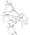
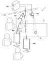
図1は、本技術の第1の実施形態に係る情報処理システム1を示す模式図である。
本実施形態の情報表示システム1は、1以上のヘッドマウントディスプレイ(Head Mount Display、HMD)100(情報処理装置)と、1以上の入力装置200(投影装置)とを有する。
<First Embodiment>
[Outline of First Embodiment]
FIG. 1 is a schematic diagram illustrating an information processing system 1 according to the first embodiment of the present technology.
The information display system 1 according to the present embodiment includes one or more head mounted displays (HMD) 100 (information processing devices) and one or more input devices 200 (projection devices).
HMD100は、全体としてメガネ型の形状を有し、ユーザUの頭部に装着可能である。HMD100は、装着時にユーザUの眼前に配置される表示部102と、現実風景の少なくともユーザUの視野範囲を撮影可能な撮影部101とを有する。表示部102は透過性を有し、ユーザU個人に表示部102を透過させて現実風景を視認させつつ、ユーザUが視認する現実風景に重畳して画像を表示することが可能である。HMD100は、撮影部101が撮影した現実風景の画像(現実画像)に含まれる、現実風景に重畳して仮想情報を表示させるために必要な空間的な情報(第1の情報)を与えるため入力装置200により現実風景に対して投影されたマーカMを検出する。HMD100は、検出したマーカMをもとに仮想情報Iの重畳パラメータを算出する。この「重畳パラメータ」とは、現実風景に重畳して表示させる仮想情報の形態に関するパラメータであり、具体的には、仮想情報Iの位置、サイズ及び角度である。HMD100は、算出した重畳パラメータに基いて所定の仮想情報を生成し、表示部102により、ユーザUの視認する現実風景に投影されたマーカMに重畳して仮想情報Iを表示する。この仮想情報Iとして表示するコンテンツの選択は、ユーザによりHMD100に設けられた入力部(図2)を用いて予め入力される。
The
入力装置200は、ユーザUが手に持つことが可能な大きさ及び形状を有する。入力装置200には、投影ボタン201、ズームスライダ202、電源ボタン203が設けられる。ユーザUが投影ボタン201を押すと、投影窓204から現実風景に重畳して仮想情報を表示させるために必要な空間的な情報(第1の情報)を与えるためのマーカMとしての所定形状の図形が現実風景の投影対象物T(机など)に投影される。このマーカMの投影位置が、HMD100による仮想情報Iの表示位置となる。さらに、ユーザUが投影ボタン201を押しながら入力装置200を動かすことで、仮想情報Iに対して操作を行うことができる。例えば、ユーザUが投影ボタン201を押しながら入力装置200を移動してマーカMの投影位置を移動すると、仮想情報Iを移動(ドラッグ)させることができる。同様に、ユーザUが投影ボタン201を押しながら入力装置200を回転してマーカMを回転すると、仮想情報Iを回転させることができる。また、ユーザUが投影ボタン201を押しながらズームスライダ202を操作すると、仮想情報Iを拡大/縮小(ズーム)させることができる。仮想情報Iを表示中に新たな別の仮想情報を表示させるためには、ユーザUは投影ボタン201の押下を停止し、HMD100に設けられた入力部(図2)を用いて新たな仮想情報として表示するコンテンツの選択を入力する。また、ユーザUが投影ボタン201の押下を停止し、その後再び投影ボタン201を押してマーカMを表示中の仮想情報Iに重ねると、再びその仮想情報Iを操作可能となる。
The
[HMDのハードウェア構成]
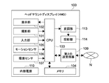
図2は、HMD100及び入力装置200のハードウェア構成を示すブロック図である。
HMD100は、CPU(Central Processing Unit)103と、それぞれCPU103に接続されたメモリ104、撮影部101、表示部102、入力部105、モーションセンサ106、環境センサ107、第1の送受信器108及び第2の送受信器109と、内部電源110とを有する。
[HMD hardware configuration]
FIG. 2 is a block diagram illustrating a hardware configuration of the
The
CPU103は、メモリ104に格納されたプログラムに従って各種処理を実行する。
撮影部101は、現実風景の少なくともユーザの視野範囲を撮影可能である。撮影部101は、CMOS(Complementary Metal Oxide Semiconductor)イメージセンサなどの撮影素子と、撮影素子の出力をA/D(Analog/Digital)変換するA/Dコンバータなどで構成される。
表示部102は、LCD(Liquid Crystal Display、液晶表示素子)と光学系などからなり、LCDによって形成された画像を光学系を介してユーザに提示する。より具体的には、表示部102は、ユーザに外界を視認させつつ、LCDによって形成された画像をユーザの視野に重ねて表示可能である。
入力部105は、例えば、ボタン、スライダ、スイッチ、ダイヤル、タッチセンサなどで構成され、ユーザ操作によりCPU103に対する命令や、仮想情報として表示するコンテンツの選択を入力可能である。
モーションセンサ106は、例えば、加速度センサ、ジャイロセンサ、磁気センサであり、HMD100の移動を検出可能である。
環境センサ107は、例えば、照度や温湿度を検出可能である。
第1の送受信器108は、例えば、Bluetooth(登録商標)、Wi−Fi(登録商標)などの中・高速近距離無線送受信器であり、入力装置200との情報のやり取りを行う。
第2の送受信器109は、例えば、3G(3rd Generation)、WiMAX(Worldwide Interoperability for Microwave Access、登録商標)などの中距離無線送受信器である。第2の送受信器109は、インターネットやLAN(Local Area Network)などのネットワークNに接続され、このネットワークNに接続されたコンテンツサーバにアクセスして仮想情報として表示するコンテンツをダウンロードしたりする。
The
The photographing
The
The
The
The
The
The
[入力装置のハードウェア構成]
図2を参照し、入力装置200は、CPU212と、それぞれCPU212に接続されたメモリ205、入力部206、モーションセンサ207、第3の送受信器208、変調部209及び投影部210と、内部電源211とを有する。
CPU212は、メモリ205に格納されたプログラムに従って各種処理を実行する。なお、CPUの代わりにMPU(Micro Processing Unit)であってもよい。
入力部206は、投影ボタン201、ズームスライダ202、電源ボタン203などのボタン、スライダ、スイッチ、ダイヤル、タッチセンサなどで構成され、ユーザ操作によりCPU212に対する命令を入力可能である。
モーションセンサ207は、例えば、加速度センサ、ジャイロセンサ、磁気センサであり、入力装置200の移動を検出可能である。
第3の送受信器208は、例えば、Bluetooth(登録商標)、Wi−Fi(登録商標)などの中・高速近距離無線送受信器であり、HMD100との情報のやり取りを行う。
変調部209は、CPU212が扱うデジタルデータを投影部210が投影可能な光信号に変調する。
投影部210は、レーザ光源と、レーザ光源が発するレーザ光を、投影窓204(図1)からマーカとしての所定形状の図形として現実風景の投影対象物(壁や机など)に投影可能な光学系とにより構成されるレーザポインタである。レーザポインタとしては、点表示型(赤、緑、青)、ビーム可変型(スキャナタイプ、レンズタイプ、ホログラムタイプ)、紫外型、赤外型などを採用することができる。
[Hardware configuration of input device]
Referring to FIG. 2, the
The
The
The
The
The
The
[HMDが実行する処理]
HMD100及び入力装置200は、以下の3つの処理を実行することが可能である。
1.入力装置200は、マーカに、自入力装置200を特定する情報(第2の情報)を付加する。HMD100は、撮影したマーカをもとに現実画像データに含まれるマーカを投影する主体である入力装置200を特定し、特定の入力装置200により投影されたマーカである場合、仮想情報を表示する(第1の処理)。
2.入力装置200は、マーカに、前記現実風景に重畳して表示させる仮想情報の形態の変更情報(第2の情報)を付加する。HMD100は、撮影したマーカをもとに仮想情報の形態の変更情報を特定し、特定した変更情報に基づき、既に表示している仮想情報の表示位置やサイズなど仮想情報の形態を変更する(第2の処理)。
3.入力装置200は、マーカに、オブジェクトのデータが保存されるネットワーク上での位置を特定するロケーション情報(第2の情報)を付加する。HMD100は、撮影したマーカをもとにオブジェクトデータのネットワーク上での位置を特定し、仮想情報をネットワークからダウンロードし、仮想情報を表示する(第3の処理)。
[Processes executed by the HMD]
The
1. The
2. The
3. The
<第1の処理>
[第1の処理の概要]
マーカ型AR及びマーカレス型ARの上記各問題を解決するため、ユーザが携帯型のレーザポインタを手に持ってマーカを投影する手法が提案されている(特許文献2)。ここで、仮に、複数のユーザが同一の投影対象物(机や壁など)に対して仮想情報を表示し、それぞれ入力装置(レーザポインタ)を用いて同時に仮想情報に対する操作を行う場合を仮定する。それぞれのユーザは、入力装置を用いてポインティング点を投影対象物に投影し、入力装置を動かすことで投影対象物に投影されたポインティング点を移動し、ポインティング点の移動とともにポインティング点に対して表示された仮想情報が移動する等の処理が行われる。このとき、仮に、複数のユーザが同じ形状のポインティング点を投影する入力装置を用いると仮定する。その場合、撮影装置がどのポインティング点がどのユーザの持つ入力装置から投影されたかを識別できず、その結果、例えば無関係のユーザがもつ入力装置が投影したポインティング点をもとに、別のユーザに対して仮想情報が表示されるなどの事態が生じるおそれがある。
<First processing>
[Overview of the first process]
In order to solve the above-described problems of the marker type AR and the markerless type AR, there has been proposed a method in which a user projects a marker while holding a portable laser pointer (Patent Document 2). Here, it is assumed that a plurality of users display virtual information on the same projection target (desk, wall, etc.) and perform operations on the virtual information simultaneously using an input device (laser pointer). . Each user projects the pointing point onto the projection object using the input device, and moves the pointing point projected onto the projection object by moving the input device, and displays the pointing point along with the movement of the pointing point. Processing such as movement of the virtual information is performed. At this time, it is assumed that a plurality of users use an input device that projects pointing points having the same shape. In this case, the imaging device cannot identify which pointing point is projected from which input device of the user, and as a result, for example, based on the pointing point projected by the input device of an irrelevant user, to another user. On the other hand, there may be a situation in which virtual information is displayed.
一方、特許文献3によれば、複数のユーザがそれぞれ入力装置としてのレーザポインタを用いて仮想情報に対する操作を行う状況において、ポインティング点の投影パターンを各入力装置によって変更することで、各複数のユーザの入力装置が区別され得ることとされる。しかしながらこの手法では、各入力装置毎に物理的に投影パターンの形状を異ならしめる必要があり、技術的・コスト的に限界があるという問題がある。とりわけ、同時に使用される入力装置の数が多い場合や、入力操作中に投影パターン変更可能な形態とする場合などには、その問題は顕著なものとなる。
On the other hand, according to
ここで、入力装置としてレーザポインタの代わりにレーザプロジェクタを用いることについて検討する。レーザプロジェクタは、例えば、MEMS(Micro Electro Mechanical System)スキャナを搭載し、高速に左右へ動く1本のレーザ光で上から順に走査する装置であり、任意の形状の図形や任意の画像を投影可能である。その一方で、レーザプロジェクタは、単純な図形投影を行うレーザポインタに比べ、複雑なハードウェア/ソフトウェア構成が要求されるという問題がある。その結果、レーザプロジェクタ自体の大型化、コストの上昇、消費電力の上昇といった問題を招くおそれがある。さらに、複数の入力装置からの投影図形の形状が異なるとしても、投影図形が互いに重なり合う場合、それぞれの投影図形を識別するのが難しいという問題もある。 Here, it is considered to use a laser projector instead of a laser pointer as an input device. A laser projector, for example, is equipped with a MEMS (Micro Electro Mechanical System) scanner and scans from top to bottom with a single laser beam moving left and right at high speed, and can project figures and images of any shape. It is. On the other hand, a laser projector has a problem that a complicated hardware / software configuration is required as compared with a laser pointer that performs simple graphic projection. As a result, there is a risk of causing problems such as an increase in size of the laser projector itself, an increase in cost, and an increase in power consumption. Furthermore, even if the shapes of the projected figures from a plurality of input devices are different, there is a problem that it is difficult to identify each projected figure when the projected figures overlap each other.
以上のような事情に鑑み、第1の処理では、HMDが、撮影したマーカがどの入力装置から投影されたのかを安定的かつ高精度に判断する。これにより、HMDは、仮想情報を表示すべきマーカを安定的かつ高精度に判断し、結果的に、仮想情報の表示を安定的かつ高精度に行う。 In view of the circumstances as described above, in the first process, the HMD determines from which input device the captured marker is projected stably and with high accuracy. Thereby, HMD judges the marker which should display virtual information stably and highly accurately, and displays virtual information stably and highly accurately as a result.
[入力装置]
入力装置200は、自入力装置を一意に識別するための情報(識別情報)が付加されたマーカを投影するように設定されている。この識別情報は、例えば入力装置200の製造時に設定されたシリアル番号などであってもよいし、ユーザが入力部206を用いて設定したユーザ名などであってもよい。より具体的には、入力装置200は、固有の光の強度(振幅)、波長(周波数)及び明滅周期の少なくともいずれか1つをもつマーカを投影するように設定されている。光の強度(振幅)、波長(周波数)及び明滅周期の個体差により、入力装置200が一意に識別され得る。
[Input device]
The
[第1の処理を実行するためのHMDの機能的な構成]
図3は、第1の処理を実行するためのHMD100の機能的な構成を示すブロック図である。
HMD100は、撮影部101、マーカ検出部121、付加情報取得部125(抽出部)、重畳パラメータ生成部122、変換行列算出部123、画像データ生成部124及び表示部102を有する。
[Functional configuration of HMD for executing first processing]
FIG. 3 is a block diagram illustrating a functional configuration of the
The
撮影部101は現実風景の画像を撮影し、現実画像データを取得する。撮影部101は、取得した現実画像データをマーカ検出部121及び付加情報取得部125に供給する。
The
付加情報取得部125は、撮影部101より現実画像データを取得する。付加情報取得部125は、画像処理により、マーカの特性、すなわち、光の強度(振幅)、波長(周波数)及び明滅周期の少なくともいずれか1つを測定する。付加情報取得部125は、測定した特性に割り当てられた入力装置200の識別情報を判断する。付加情報取得部125は、判断した識別情報によって表される入力装置200が、仮想情報の投影対象であるかどうかを判断する。ここで、付加情報取得部125には、どの入力装置200から投影されたマーカに対して仮想情報を表示するか、すなわち仮想情報の投影対象としての1以上の入力装置200が予め登録されている。この仮想情報の投影対象は、例えば、ユーザが入力部105を用いて設定したものである。付加情報取得部125は、判断結果を重畳パラメータ生成部122に通知する。
The additional
マーカ検出部121は、撮影部101が取得した現実画像データから、入力装置200により投影されたマーカを検出する。マーカ検出部121には予め基準マーカの情報が登録されている。この「基準マーカ」とは、マーカを所定の距離から垂直方向に投影した場合のあらかじめ決められた基準形状を有するマーカであり、「基準マーカの情報」とは、基準マーカのサイズ、各頂点同士の距離、各辺の長さ等である。マーカ検出部121は、基準マーカのサイズをもとに、現実画像データから検出したマーカが基準マーカの形状と一致するような平面座標変換行列を生成し、検出したマーカに対して平面座標変換行列を用いた座標変換を行う。続いてマーカ検出部121は、座標変換されたマーカに対し、基準マーカとのパターンマッチングを行い、検出したマーカと基準マーカとの一致度を判断する。マーカ検出部121は、判断結果を重畳パラメータ生成部122に供給する。
The
重畳パラメータ生成部122は、仮想情報の投影対象である入力装置200から投影され、所定の一致度をもつマーカについて、基準マーカに対するマーカの歪みをもとに、投影対象物(壁や机など)に投影されたマーカに対する撮影部101の空間的な位置関係、すなわち角度及び距離を算出する。さらに、重畳パラメータ生成部122は、図4に示すように、輪郭抽出によりマーカMの座標系(A)を算出する。重畳パラメータ生成部122は、マーカに対する撮影部101の上記空間的な位置関係をもとに、マーカMの座標系(A)と、予め設定してある仮想情報Iの座標系(B)とが一致した座標系(C)となるように、仮想情報の重畳パラメータを計算する。重畳パラメータ生成部122は、モーションセンサ106により検出されたHMD100の位置と、入力装置200のモーションセンサ106により検出された入力装置200の位置との関係をもとに、仮想情報がユーザにとってより自然に表示されるように重畳パラメータを補正する。さらに重畳パラメータ生成部122は、ユーザの眼と表示部102との位置関係をもとに重畳パラメータを補正する。
The superimposition
変換行列算出部123は、マーカを基準とした座標系を現実風景における撮影部101を基準とした座標系に重畳パラメータで変換するための空間座標変換行列を生成する。画像データ生成部124は、予め記録された仮想情報のオブジェクトデータを、変換行列算出部123から供給された空間座標変換行列を用いて座標変換する。これにより、画像データ生成部124は、撮影部101を基準とした座標系での、仮想情報のオブジェクト画像データを算出(描画)する。
The transformation
画像データ生成部124は、生成した仮想情報のオブジェクト画像データを表示部102に供給する。
表示部102は、変換行列算出部123より供給された仮想情報のオブジェクト画像データを表示する。
The image
The
[HMDによる第1の処理の動作]
図5は、HMD100による第1の処理の動作を示すフローチャートである。
CPU103が所定の初期化処理を行うと(ステップS101)、撮影部101は現実風景の画像を撮影し、現実画像データを取得する(ステップS102)。撮影部101は、取得した現実画像データをマーカ検出部121及び付加情報取得部125に供給する。
[Operation of first process by HMD]
FIG. 5 is a flowchart showing the operation of the first process performed by the
When the
マーカ検出部121は、撮影部101が取得(ステップS102)した現実画像データから、入力装置200により投影されたマーカを検出する(ステップS103)。マーカ検出部121は、基準マーカのサイズをもとに、現実画像データから検出したマーカが基準マーカの形状と一致するような平面座標変換行列を生成し、検出したマーカに対して平面座標変換行列を用いた座標変換を行う。続いてマーカ検出部121は、座標変換されたマーカに対し、基準マーカとのパターンマッチングを行い、検出したマーカと基準マーカとの一致度を判断する(ステップS104)。マーカ検出部121は、判断結果を重畳パラメータ生成部122に供給する。
The
一方、付加情報取得部125も、撮影部101より現実画像データを取得する。付加情報取得部125は、画像処理により、マーカの特性、すなわち、光の強度(振幅)、波長(周波数)及び明滅周期の少なくともいずれか1つを測定する。付加情報取得部125は、測定した特性に割り当てられた入力装置200の識別情報を判断する(ステップS105)。付加情報取得部125は、判断した識別情報によって表される入力装置200が、仮想情報の投影対象と一致するかどうかを判断し(ステップS106)、判断結果を重畳パラメータ生成部122に通知する。
On the other hand, the additional
重畳パラメータ生成部122は、仮想情報の投影対象である(ステップS106でYes)入力装置200から投影され、所定の一致度をもつ(ステップS104でYes)マーカについて、基準マーカに対するマーカの歪みをもとに、マーカに対する撮影部101の空間的な位置関係を推定する。具体的には、重畳パラメータ生成部122は、投影対象物(壁など)に投影されたマーカに対する撮影部101の空間的な位置関係、すなわち角度及び距離を算出する。さらに、重畳パラメータ生成部122は、マーカの座標系と仮想情報の座標系とが一致するように、仮想情報の重畳パラメータを計算する(ステップS107)。そして、重畳パラメータ生成部122は、仮想情報がユーザにとってより自然に表示されるように重畳パラメータを補正する(ステップS108)。
The superimposing
変換行列算出部123は、マーカを基準とした座標系を、現実風景における撮影部101を基準とした座標系に、重畳パラメータで変換するための空間座標変換行列を生成する(ステップS109)。画像データ生成部124は、予めに記録された仮想情報のオブジェクトデータを、変換行列算出部123から供給された空間座標変換行列を用いて座標変換する。これにより、画像データ生成部124は、撮影部101を基準とした座標系での、仮想情報のオブジェクト画像データを算出(描画)する(ステップS110)。画像データ生成部124は、生成した仮想情報のオブジェクト画像データを表示部102に供給する。表示部102は、供給された仮想情報のオブジェクト画像データを表示する(ステップS111)。この後、次フレームの現実風景の画像データの取得(ステップS102)から仮想情報のオブジェクト画像データの表示(ステップS111)までの処理が繰り返し実行される。
The conversion
[第1の処理の効果]
以上、第1の処理によれば、次のような効果が期待できる。
1.仮に、HMDがどのマーカがどの入力装置から発せられたかを識別できないとすると、HMDが、無関係のユーザが持つ入力装置が投影したマーカに対して仮想情報を表示するなどの事態が生じるおそれがある。
これに対して、第1の処理では、図6に示すように、マーカMLに付加される入力装置200Aの識別情報を識別可能なHMD100A、100BはマーカMに対してそれぞれ仮想情報Iaを表示することができる。しかしながら、マーカMLに付加される入力装置200Aの識別情報を識別不可のHMD100Cは、取得する現実画像データにマーカMが含まれているにも拘わらず、マーカMに対して仮想情報を表示することができない。これにより、マーカMを投影する入力装置200AをもつユーザU1のHMD100AやユーザU1の関係者であるユーザU2のHMD100Bに仮想情報の表示を許可し、無関係なユーザU3のHMD100Cに仮想情報の表示を不許可とすることができる。
[Effect of first processing]
As described above, according to the first process, the following effects can be expected.
1. If the HMD cannot identify which marker is emitted from which input device, the HMD may display virtual information on the marker projected by the input device held by an irrelevant user. .
On the other hand, in the first process, as shown in FIG. 6, the
2.マーカの形状を異ならしめて個々の入力装置を区別する技術では、投影されたマーカが投影対象物上で互いに重なり合う場合、それぞれのマーカを識別するのが難しく、結果的に、それぞれのマーカの投影元の各入力装置を識別するのが難しいという問題がある。
これに対して、第1の処理では、マーカに入力装置の識別情報が付加されているため、マーカ同士の重なり合いに関係なく、マーカの光の強度(振幅)、波長(周波数)及び明滅周期の少なくともいずれか1つをもとに、投影元の入力装置を安定的かつ高精度に判断することができる。また、各入力装置毎に物理的にマーカの形状を異ならしめる技術に比べて低コストであり、様々な形状のマーカを投影可能なレーザポインタを用いる技術に比べて単純な複雑なハードウェア/ソフトウェア構成で実現可能であるというメリットもある。
2. In the technique of distinguishing individual input devices by making the shape of the marker different, it is difficult to identify each marker when the projected markers overlap each other on the projection target, and as a result, the projection source of each marker There is a problem that it is difficult to identify each input device.
On the other hand, in the first process, since the identification information of the input device is added to the marker, the light intensity (amplitude), wavelength (frequency), and blinking period of the marker are not related to the overlapping of the markers. Based on at least one of them, the projection source input device can be determined stably and with high accuracy. In addition, the hardware and software are simpler and more complex than the technique using a laser pointer capable of projecting markers of various shapes, which is lower in cost than the technique of physically making the marker shape different for each input device. There is also an advantage that it can be realized by the configuration.
<第2の処理>
以下、すでに説明した構成等と異なる点を中心に説明し、重複する説明は省略する。
第1の処理では、マーカに対する付加情報として入力装置200の識別情報が付加された。これに対して第2の処理では、マーカに対する付加情報として、現実風景に重畳して表示させる仮想情報の形態の変更情報が付加される。
<Second processing>
The following description will focus on differences from the already described configuration and the like, and repeated description will be omitted.
In the first process, the identification information of the
[入力装置]
ユーザにより入力装置200の入力部206にボタン押下など所定の操作が入力されると、CPU212は、マーカの移動、回転、拡大/縮小(ズーム)など、マーカ表示形態の変更情報が入力されたと判断する。ここで、マーカの移動、回転、拡大/縮小(ズーム)など、マーカ表示形態の変更情報には、マーカの特性(光の強度(振幅)、波長(周波数)及び明滅周期の少なくともいずれか1つ)が固有に割り当てられている。例えば、マーカの拡大には周波数の増大が、マーカの縮小には周波数の減少が割り当てられている。CPU212は、入力部206よりマーカ表示形態の変更情報が入力されたと判断すると、当該マーカ表示形態の変更情報に割り当てられた特性(光の強度(振幅)、波長(周波数)及び明滅周期の少なくともいずれか1つ)で投影中のマーカを変化させる。
[Input device]
When a user inputs a predetermined operation such as pressing a button to the
[HMD]
HMD100の付加情報取得部125は、画像処理により、撮影部101より取得した現実画像データに含まれるマーカの特性(光の強度(振幅)、波長(周波数)及び明滅周期の少なくともいずれか1つ)を測定する。付加情報取得部125は、特性の変化を検出すると、変化後の特性に割り当てられたマーカ表示形態の変更情報を判断する。ここで、付加情報取得部125には、マーカの特性(光の強度(振幅)、波長(周波数)及び明滅周期の少なくともいずれか1つ)がどのように変化すると、そのマーカに対して表示される仮想情報をどのように変化させるかが予め登録されている。例えば、周波数の増大にはマーカの拡大が、周波数の減少にはマーカの縮小が登録されている。付加情報取得部125は、判断結果を重畳パラメータ生成部122に通知する。
[HMD]
The additional
なお、入力装置200のマーカに対する付加情報として、仮想情報の形態の変更情報のほか、決定、戻るなど、アプリケーションに対する命令が付加されてもよい。HMD100は、マーカに付加されたアプリケーションに対する命令に従ってアプリケーションを実行すればよい。
Note that as additional information for the marker of the
[第2の処理の効果]
以上、第2の処理によれば、次のような効果が期待できる。
ユーザが入力装置200を手に持ってこの入力装置200を移動させなくても、入力装置206に対する所定の入力操作だけで仮想情報の移動や回転など仮想情報の形態の変更情報を入力することができる。このため、例えば、入力装置200をテーブルなどに載置した状態で仮想情報の形態の変更情報を入力することができ、ユーザにとっての利便性が向上する。
[Effect of second processing]
As described above, according to the second process, the following effects can be expected.
Even if the user does not move the
<第3の処理>
図7は、第3の処理を模式的に示す図である。
マーカMを投影する入力装置200AをもつユーザU1に装着されるHMD(以下「投影HMD」と呼ぶ)100Aは、入力装置200Aに、仮想情報として表示されるオブジェクトのデータが保存されるネットワーク上での位置を特定するロケーション情報を供給する。入力装置200Aは、取得したロケーション情報をマーカに付加する。マーカMを投影する入力装置200AをもたないユーザU2、U3の装着するHMD(以下「非投影HMD」と呼ぶ)100B、100Cは、撮影したマーカからロケーション情報を抽出する。この位置情報をもとに、非投影HMD100B、100Cは、仮想情報として表示するオブジェクトのデータをネットワークNに接続されたコンテンツサーバ300からダウンロードすることが可能となる。
<Third processing>
FIG. 7 is a diagram schematically illustrating the third process.
An HMD (hereinafter referred to as “projection HMD”) 100A attached to a user U1 who has an
[第3の処理を実行するためのHMDの機能的な構成]
図8は、第3の処理を実行するためのHMD100の機能的な構成を示すブロック図である。
HMD100は、位置情報取得部130、第1の送受信器108、撮影部101、復調部132、オブジェクトデータ取得部131、第2の送受信器109を有する。
位置情報取得部130及び第1の送受信器108は(1)投影HMD100に特有の機能、撮影部101及び復調部132は(2)非投影HMD100に特有の機能である。オブジェクトデータ取得部131及び第2の送受信器109は(3)投影HMD100/非投影HMD100に共通の機能である。
[Functional configuration of HMD for executing third processing]
FIG. 8 is a block diagram showing a functional configuration of the
The
The position
[(1)投影HMDに特有の機能]
位置情報取得部130は、仮想情報として表示されるオブジェクトのデータが保存されるネットワークN上での位置を特定するロケーション情報を取得する。この「ロケーション情報」とは、具体的には、URL(Uniform Resource Locator)、ローカルネットワークパスなどである。例えば、位置情報取得部130は、第2の送受信器109を用いて、ネットワークNを通じてロケーション情報を取得してもよいし、ユーザにより入力部105を用いて入力されたロケーション情報を取得してもよい。位置情報取得部130は、取得したロケーション情報をオブジェクトデータ取得部131に供給する。さらに、位置情報取得部130は、取得した位置情報を符号化して符号化情報を生成し、生成した符号化情報を第1の送受信器108を用いて入力装置200に送信する。
[(1) Function peculiar to projection HMD]
The position
[(2)非投影HMD100に特有の機能]
撮影部101は、現実風景の画像を撮影して現実画像データを取得し、取得した現実画像データを復調部132に供給する。
[(2) Function peculiar to non-projection HMD100]
The photographing
復調部132は、画像処理により、現実画像データに含まれるマーカの光の強度(振幅)又は波長(周波数)の変化を測定し、これもとに符号化情報を抽出し、取りだした符号化情報を復号して付加情報としてのロケーション情報を得る。すなわち復調部132は、付加情報取得部として機能する。復調部132は、ロケーション情報をオブジェクトデータ取得部131に供給する。
The demodulator 132 measures a change in the light intensity (amplitude) or wavelength (frequency) of the marker included in the real image data by image processing, extracts encoding information based on the change, and extracts the extracted encoding information. Is decoded to obtain location information as additional information. That is, the
[(3)投影HMD100/非投影HMD100に共通の機能]
オブジェクトデータ取得部131は、位置情報取得部130又は復調部132から取得したロケーション情報をもとに、第2の送受信器109を用いて、ネットワークNを通じてコンテンツサーバ300よりオブジェクトデータをダウンロードする。
[(3) Functions Common to Projection HMD100 / Non-Projection HMD100]
The object
[第3の処理を実行するための入力装置のハードウェア構成]
図9は、第3の処理を実行するための入力装置200のハードウェア構成を示すブロック図である。
入力装置200は、CPU212と、入力部206と、第3の送受信器208と、変調部209と、投影部210を構成するレーザ光源220及び光学系222とを有する。
[Hardware Configuration of Input Device for Executing Third Processing]
FIG. 9 is a block diagram illustrating a hardware configuration of the
The
CPU212は、入力部206に対するユーザによる入力操作を検出し、レーザ光源220をオン/オフする。また、CPU212は、第3の送受信器208を用いてHMD100より位置情報が符号化された情報である符号化情報を取得する。CPU212は、この符号化情報をマーカに変調(振幅変調又は周波数変調)するための情報である変調情報を生成し、生成した変調情報を変調部209に供給する。
The
変調部209は、CPU212から取得した変調情報でレーザ光源220が発するマーカを変調(振幅変調又は周波数変調)する。これにより、マーカに位置情報が符号化された情報である符号化情報が付加される。
The
光学系222は、変調されたマーカを投影窓204より現実風景に投影する。
The
なお、本実施形態ではHMD100が位置情報を符号化して符号化情報を生成し、符号化情報を入力装置200に送信するとした。これに代えて、HMD100が位置情報を入力装置200に送信し、入力装置200が位置情報を符号化して符号化情報を生成することとしてもよい。
また、本実施形態では仮想情報として表示されるオブジェクトのデータが保存されるネットワーク上での位置を特定するロケーション情報の符号化情報を付加情報とした。これに代えて、第1の処理で述べた符号化情報は入力装置200の識別情報の符号化情報や、第2の処理で述べた仮想情報の形態の変更情報の符号化情報を付加情報としてもよい。
In the present embodiment, the
In this embodiment, the encoded information of the location information for specifying the position on the network where the data of the object displayed as the virtual information is stored is used as the additional information. Instead, the encoded information described in the first process uses the encoded information of the identification information of the
[第3の処理の効果]
以上、第3の処理によれば、次のような効果が期待できる。
マーカを投影する入力装置をもつユーザのHMDが、当該マーカに対して表示すべき仮想情報のオブジェクトのデータを保持しており(データ保持HMDとする)、このオブジェクトを複数のHMD(データ非保持HMDとする)がそれぞれ表示する場面を仮定する。この場合、複数のデータ非保持HMDがオブジェクトのデータを取得するには、例えば、各複数のデータ非保持HMDがデータ保持HMDから無線通信などによりデータを取得する手法などが考えられる。しかしながらこの手法では、データ非保持HMDがデータ保持HMDにアクセスできないこと等により通信が成立しなければ、データ非保持HMDは仮想情報を表示することができない。
これに対して、第3の処理によれば、HMD同士が直接通信を行ってオブジェクトのデータを共有する必要がない。不特定多数のHMDがそれぞれ現実画像データからロケーション情報を抽出し、このロケーション情報をもとにネットワークからオブジェクトのデータを取得して、同一のオブジェクトを表示することが可能となる。このような技術は、例えば、公共の場で不特定多数のユーザにサイネージを提示する用途などに適用することが可能である。
[Effect of third processing]
As described above, according to the third process, the following effects can be expected.
A user's HMD having an input device that projects a marker holds data of a virtual information object to be displayed with respect to the marker (referred to as a data holding HMD), and this object is stored in a plurality of HMDs (data non-holding). Suppose that each screen is displayed by HMD). In this case, for example, a method in which each of the plurality of data non-holding HMDs acquires data from the data holding HMD by wireless communication or the like can be considered. However, in this method, if communication is not established because the data non-holding HMD cannot access the data holding HMD or the like, the data non-holding HMD cannot display virtual information.
On the other hand, according to the third process, it is not necessary for the HMDs to directly communicate with each other to share object data. An unspecified number of HMDs each extract location information from real image data, acquire object data from the network based on the location information, and display the same object. Such a technique can be applied to, for example, a purpose of presenting signage to an unspecified number of users in a public place.
<変形例1>
上記実施形態において入力装置200の投影光の振幅(強度)を変化させることにより情報を付加する場合の変形例について説明する。HMD100は、入力装置200が投影するマーカの光強度変更パターンを検知可能なフィルタ(明滅周期同期PLL(Phase-Locked Loop)、微分フィルタなど)をさらに有してもよい。その場合、マーカ検出部121は、このフィルタを通した現実画像データからマーカを検出する。
上記実施形態において入力装置200の投影光の周波数(波長)を変化させることにより情報を付加する場合の変形例について説明する。HMD100は、入力装置200が投影するマーカの波長変更パターンを検知可能なフィルタ(波長選択フィルタ、微分フィルタなど)をさらに有してもよい。その場合、マーカ検出部121は、このフィルタを通した現実画像データからマーカを検出する。
<Modification 1>
A modification in the case where information is added by changing the amplitude (intensity) of the projection light of the
A modification in the case where information is added by changing the frequency (wavelength) of the projection light of the
フィルタを用いないとすると、強い太陽光(西日、金属反射光)や強い電灯光などの外乱光により、HMD100による現実画像データに含まれるマーカの認識率(S/N(Signal/Noise))が低下し、誤認識や計算誤差が発生するおそれがある。しかながら、フィルタを用いることで、外乱光の下でも安定的かつ高精度に仮想情報の表示及び入力操作を行うことができる。
If no filter is used, the recognition rate (S / N (Signal / Noise)) of the marker included in the real image data by the
<変形例2>
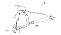
図10は、変形例2に係る情報処理システム3を示す模式図である。図11は、変形例2に係る情報処理システム3のハードウェア構成を示すブロック図である。
情報処理システム3は、HMD100b、入力装置200及び携帯情報端末400を有する。上記各実施形態では、HMD100、100aに設けられたCPU103がメイン処理を実行した。これに対して、本変形例の情報処理システムは、HMD100bとは独立した携帯情報端末400がメイン処理を実行する。この携帯情報端末400として例えばスマートフォンや携帯型ゲーム機を採用することができる。
<Modification 2>
FIG. 10 is a schematic diagram illustrating an
The
HMD100bは、第1の実施形態のHMD100のハードウェア構成から第1の送受信器108及び第2の送受信器109を除き、第5の送受信器112をさらに有する。第5の送受信器112は、例えば、Bluetooth(登録商標)などの中・低速近距離無線送受信器であり、携帯情報端末400との情報のやり取りを行う。より具体的には、第5の送受信器112は、撮影部が取得した現実画像の画像入力信号を携帯情報端末400に送信するなどの処理を行う。
The
入力装置200aは、第1の実施形態の入力装置200のハードウェア構成から第3の送受信器208を除き、第6の送受信器をさらに有する。第6の送受信器213は、Bluetooth(登録商標)、赤外線などの近距離無線送受信器であり、携帯情報端末400との情報のやり取りを行う。より具体的には、第6の送受信器213は、ユーザにより入力部に入力されたズーム操作などの操作入力信号を携帯情報端末400に送信するなどの処理を行う。
The
HMD100bが第1の送受信器108を有さず、入力装置200aが第2の送受信器を有さないことから、HMD100bと入力装置200aとは直接情報のやり取りを行わず、HMD100bと入力装置200aとの情報のやり取りは携帯情報端末400を介して行われる。
Since the
携帯情報端末400は、CPU401と、それぞれCPU401に接続されたメモリ402、表示部403、入力部404、第7の送受信器及405、第8の送受信器406及び第9の送受信器408と、内部電源407とを有する。
CPU401は、メモリ402に格納されたプログラムに従って、上記各実施形態で述べた各機能部として各種処理を実行する。
第7の送受信器405は、例えば、Bluetooth(登録商標)などの中・低速近距離無線送受信器であり、HMD100bとの情報のやり取りを行う。より具体的には、第7の送受信器405は、HMD100bの表示部が表示すべき仮想情報の画像出力信号をHMD100bに送信するなどの処理を行う。
第8の送受信器406は、Bluetooth(登録商標)、赤外線などの近距離無線送受信器であり、入力装置200aとの情報のやり取りを行う。より具体的には、第8の送受信器406は、入力装置200aが投影するマーカとしての図形のパターンを変更するための変更信号を入力装置200aに送信するなどの処理を行う。
第9の送受信器408は、例えば、3G(3rd Generation)、WiMAX(Worldwide Interoperability for Microwave Access、登録商標)などの中距離無線送受信器であり、インターネットやLAN(Local Area Network)などのネットワークNに接続し、仮想情報として表示するコンテンツをダウンロードしたりする。
The
The
The seventh transmitter /
The eighth transmitter /
The ninth transmitter /
なお、HMD100bの第5の送受信器112と携帯情報端末400の第7の送受信器405とは、それぞれ有線送受信器であってもよい。
Note that the fifth transmitter /
<変形例3>
図12は、変形例3に係る情報処理システム4を示す模式図である。
本変形例の情報処理システム4のハードウェア構成は、第1の実施形態の情報処理システム1のハードウェア構成(図2)と同様である。
上記実施形態では、HMDに設けられたCPUがメイン処理を実行した。これに対して、本変形例の情報処理システム4は、入力装置200としての携帯情報端末がメイン処理を実行する。この携帯情報端末として例えばスマートフォンや携帯型ゲーム機を採用することができる。
<
FIG. 12 is a schematic diagram illustrating an
The hardware configuration of the
In the above embodiment, the CPU provided in the HMD performs the main process. On the other hand, in the
HMD100の第1の送受信器108は、撮影部101が取得した現実画像の画像入力信号を入力装置(携帯情報端末)200に送信するなどの処理を行う。
The first transmitter /
入力装置(携帯情報端末)200の第3の送受信器208は、HMD100の表示部102が表示すべき仮想情報の画像出力信号をHMD100に送信するなどの処理を行う。
入力装置(携帯情報端末)200のCPU212は、メモリ205に格納されたプログラムに従って、上記実施形態で述べた各機能部として各種処理を実行する。
The third transmitter /
The
なお、表示部102及び撮影部101が1つの装置(HMD100)に搭載されている場合、重畳パラメータ補正(ステップS110)は、HMD100の位置と入力装置200の位置との関係をもとに行えばよい。
When the
<変形例4>
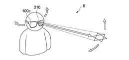
図13は、変形例4に係る情報処理システム5を示す模式図である。図14は、変形例4に係る情報処理システム5のハードウェア構成を示すブロック図である。
上記実施形態では、HMD100とは独立した入力装置200を用いてマーカ投影や仮想情報に対する入力操作を行った。これに対して本変形例では、入力装置を別途設けずに、HMD100cのみでマーカ投影や仮想情報に対する入力操作を含む全ての動作を実現する。
<
FIG. 13 is a schematic diagram illustrating an
In the embodiment described above, marker projection and input operation for virtual information are performed using the
HMD100cは、第1の実施形態のHMD100のハードウェア構成から第1の送受信器108を除き、CPU103に接続された変調部113と、変調部113に接続された投影部114とをさらに有する。変調部113及び投影部114は、上記実施形態の入力装置200に設けられた変調部209及び投影部210の機能と同様の機能を有する。
ユーザは、HMD100cを装着した状態で首を動かすことで、仮想情報に対して操作を行うことができる。例えば、ユーザが首を上下左右に向けてマーカの投影位置を移動すると、表示される仮想情報の表示位置を移動(ドラッグ)させることができる。
The
The user can operate the virtual information by moving the neck while wearing the
<変形例5>
図15は、変形例5に係る情報処理システム6を示す模式図である。
情報処理システム6は、複数のHMD100A、100B、100Cと、複数の入力装置200と、仮想情報として表示されるコンテンツのコンテンツデータを保持するサーバ装置500とを有する。
<
FIG. 15 is a schematic diagram illustrating an information processing system 6 according to the fifth modification.
The information processing system 6 includes a plurality of
投影HMD100Aは、無線又は有線LAN(Local Area Network)を通じてサーバ装置500から、仮想情報として表示されるコンテンツのコンテンツデータを検索して取得する。投影HMD100Aは、近距離無線送受信器(第4の送受信器111)を用いて、非投影HMD100B、100Cにサーバ装置500から取得したコンテンツデータを供給する。これにより、投影HMD100A及び非投影HMD100B、100Cはそれぞれ同一のコンテンツを仮想情報として表示することができる。
The
<変形例6>
図16は、変形例6に係る情報処理システム7を示す模式図である。
情報処理システムは、メイン処理装置600と、投影/撮影装置700と、1以上の表示装置800とを有する。
<Modification 6>
FIG. 16 is a schematic diagram illustrating an
The information processing system includes a
メイン処理装置600は、投影すべきマークMの形状や現実風景S内の位置などを、近距離無線又は有線通信により投影/撮影装置700に命令する。また、メイン処理装置600は、現実画像データを投影/撮影装置700より取得し、取得した現実画像データをもとに仮想情報のオブジェクト画像データを算出する。メイン処理装置600は、算出したオブジェクト画像データを現実画像データに重畳して表示データを生成し、生成した表示データを無線通信により複数の表示装置800に供給する。
投影/撮影装置700は、マーカMを現実風景Sに投影し、定点カメラにより現実風景Sを撮影して現実画像データを取得し、取得した現実画像データをメイン処理装置600に供給する。
表示装置800は、メイン処理装置600から取得した表示データを表示する。表示装置800は、例えば、HUD(Head-Up Display)である。HUDとして、具体的には、デジタルサイネージ(電子看板)、机上や車ダッシュボード上に載置され得る透明ディスプレイ、携帯情報端末のディスプレイなどを採用することができる。
The
The projection /
The
<変形例7>
マーカ投影の光源として、可視領域外(赤外、紫外など)レーザを使用してもよい。これにより、HMDを装着しないユーザにマーカ及び仮想情報を視認させないようにすることができる。一方、HMDを装着するユーザは仮想情報を視認可能である。さらに、HMDの表示部に可視領域外(赤外、紫外など)レーザを視認可能とする処置を施すことにより、HMDを装着するユーザはマーカを視認可能としてもよい。
<
As a light source for marker projection, a laser outside the visible region (infrared, ultraviolet, etc.) may be used. Thereby, it is possible to prevent the user who does not wear the HMD from visually recognizing the marker and the virtual information. On the other hand, the user wearing the HMD can visually recognize the virtual information. Furthermore, the user who wears the HMD may be able to visually recognize the marker by performing a treatment for allowing the laser outside the visible region (infrared, ultraviolet, etc.) to be visible on the display unit of the HMD.
なお、本技術は以下のような構成も採ることができる。
(1)現実風景を撮影して現実画像を取得する撮影部と、
前記現実風景に重畳して仮想情報を表示させるために必要な空間的な第1の情報を与えるため投影装置により前記現実風景に対して投影されたマーカ投影光であって、第2の情報が付加されたマーカ投影光の画像をマーカ画像として前記現実画像から抽出するマーカ検出部と、
前記抽出されたマーカ画像に付加された前記第2の情報を抽出する抽出部と
を具備する情報処理装置。
(2)上記(1)に記載の情報処理装置であって、
前記マーカ投影光には、測定可能な特性が前記の第2の情報として付与され、
前記抽出部は、前記マーカ投影光の画像から前記特性を測定して第2の情報を抽出する
情報処理装置。
(3)上記(1)又は(2)に記載の情報処理装置であって、
前記マーカ投影光の測定可能な特性は、光の強度(振幅)、波長(周波数)及び明滅周期のうち少なくともいずれか1つである
情報処理装置。
(4)上記(1)から(3)のいずれか1つに記載の情報処理装置であって、
前記第1の情報をもとに、前記現実風景に重畳して表示させる仮想情報の画像を生成する画像生成部
をさらに具備する情報処理装置。
(5)上記(1)から(4)のいずれか1つに記載の情報処理装置であって、
前記第2の情報は、前記投影装置を一意に識別する識別情報であり、
前記抽出部は、抽出した識別情報が、仮想情報の投影対象の入力装置を示すかどうかを判断し、
前記画像生成部は、前記抽出部が抽出した識別情報が仮想情報の投影対象の入力装置を示すと判断すると、前記仮想情報の画像を生成する
情報処理装置。
(6)上記(1)から(5)のいずれか1つに記載の情報処理装置であって、
前記マーカ投影光の特性を検知可能なフィルタをさらに有し、
前記マーカ検出部は、前記フィルタを通した現実画像からマーカ画像を検出する
情報処理装置。
(7)上記(1)から(6)のいずれか1つに記載の情報処理装置であって、
前記仮想情報の画像を前記現実風景に重畳して表示する表示部
をさらに具備する情報処理装置。
(8)上記(1)から(7)のいずれか1つに記載の情報処理装置であって、
前記第2の情報は、前記現実風景に重畳して表示させる仮想情報の形態の変更情報であり、
前記画像生成部は、前記抽出部が抽出した仮想情報の形態の変更情報をもとに、前記仮想情報の画像を生成する
情報処理装置。
(9)上記(1)から(8)のいずれか1つに記載の情報処理装置であって、
前記情報処理装置は、前記投影装置がマーカ画像に付加する第2の情報を前記投影装置に送信する送信部をさらに有し、
前記投影装置によりマーカ画像に付加された前記第2の情報は、前記投影装置が前記情報処理装置から受信した前記第2の情報を前記マーカ投影光に変調することで前記マーカ画像に付加されたものであり、
前記抽出部は、前記マーカ画像に付加された前記第2の情報を復調する
情報処理装置。
(10)上記(1)から(9)のいずれか1つに記載の情報処理装置であって、
前記第2の情報は、仮想情報として表示されるオブジェクトのデータが保存される位置を特定するロケーション情報であり、
前記情報処理装置は、前記抽出部が抽出したロケーション情報をもとに、仮想情報として表示されるオブジェクトのデータを取得するオブジェクトデータ取得部をさらに具備する
情報処理装置。
In addition, this technique can also take the following structures.
(1) a photographing unit for photographing a real landscape and acquiring a real image;
Marker projection light projected onto the real scene by a projection device to give spatial first information necessary for displaying virtual information superimposed on the real scene, wherein the second information is A marker detection unit that extracts an image of the added marker projection light as a marker image from the real image;
An information processing apparatus comprising: an extraction unit that extracts the second information added to the extracted marker image.
(2) The information processing apparatus according to (1) above,
The marker projection light is given a measurable characteristic as the second information,
The extraction unit measures the characteristic from the image of the marker projection light and extracts second information.
(3) The information processing apparatus according to (1) or (2) above,
The measurable characteristic of the marker projection light is at least one of light intensity (amplitude), wavelength (frequency), and blinking cycle.
(4) The information processing apparatus according to any one of (1) to (3),
An information processing apparatus further comprising: an image generation unit configured to generate an image of virtual information to be displayed superimposed on the real landscape based on the first information.
(5) The information processing apparatus according to any one of (1) to (4) above,
The second information is identification information for uniquely identifying the projection device,
The extraction unit determines whether the extracted identification information indicates an input device to be projected with virtual information,
The image generation unit generates an image of the virtual information when determining that the identification information extracted by the extraction unit indicates a virtual information projection target input device.
(6) The information processing apparatus according to any one of (1) to (5),
A filter capable of detecting the characteristics of the marker projection light;
The marker detection unit detects a marker image from a real image that has passed through the filter.
(7) The information processing apparatus according to any one of (1) to (6) above,
An information processing apparatus further comprising: a display unit configured to display an image of the virtual information superimposed on the real landscape.
(8) The information processing apparatus according to any one of (1) to (7) above,
The second information is change information in the form of virtual information to be displayed superimposed on the real landscape,
The image generation unit generates an image of the virtual information based on change information of the form of virtual information extracted by the extraction unit.
(9) The information processing apparatus according to any one of (1) to (8),
The information processing apparatus further includes a transmission unit that transmits second information added to the marker image by the projection apparatus to the projection apparatus,
The second information added to the marker image by the projection device is added to the marker image by modulating the second information received by the projection device from the information processing device into the marker projection light. Is,
The extraction unit demodulates the second information added to the marker image.
(10) The information processing apparatus according to any one of (1) to (9),
The second information is location information for specifying a position where data of an object displayed as virtual information is stored;
The information processing apparatus further includes an object data acquisition unit that acquires data of an object displayed as virtual information based on the location information extracted by the extraction unit.
100…HMD
101…撮影部
121…マーカ検出部
122…重畳パラメータ生成部
123…変換行列算出部
124…画像データ生成部
125…付加情報取得部
130…位置情報取得部
131…オブジェクトデータ取得部
132…復調部
200…入力装置
100 ... HMD
DESCRIPTION OF
Claims (1)
前記現実風景に重畳して仮想情報を表示させるために必要な空間的な第1の情報を与えるため投影装置により前記現実風景に対して投影されたマーカ投影光であって、第2の情報が付加されたマーカ投影光の画像をマーカ画像として前記現実画像から抽出するマーカ検出部と、
前記抽出されたマーカ画像に付加された前記第2の情報を抽出する抽出部と
を具備する情報処理装置。 A shooting unit for shooting a real scene and acquiring a real image;
Marker projection light projected onto the real scene by a projection device to give spatial first information necessary for displaying virtual information superimposed on the real scene, wherein the second information is A marker detection unit that extracts an image of the added marker projection light as a marker image from the real image;
An information processing apparatus comprising: an extraction unit that extracts the second information added to the extracted marker image.
Priority Applications (1)
| Application Number | Priority Date | Filing Date | Title |
|---|---|---|---|
| JP2016072692A JP2016157458A (en) | 2016-03-31 | 2016-03-31 | Information processing apparatus |
Applications Claiming Priority (1)
| Application Number | Priority Date | Filing Date | Title |
|---|---|---|---|
| JP2016072692A JP2016157458A (en) | 2016-03-31 | 2016-03-31 | Information processing apparatus |
Related Parent Applications (1)
| Application Number | Title | Priority Date | Filing Date |
|---|---|---|---|
| JP2012087184A Division JP5912059B2 (en) | 2012-04-06 | 2012-04-06 | Information processing apparatus, information processing method, and information processing system |
Publications (2)
| Publication Number | Publication Date |
|---|---|
| JP2016157458A true JP2016157458A (en) | 2016-09-01 |
| JP2016157458A5 JP2016157458A5 (en) | 2016-10-13 |
Family
ID=56826187
Family Applications (1)
| Application Number | Title | Priority Date | Filing Date |
|---|---|---|---|
| JP2016072692A Pending JP2016157458A (en) | 2016-03-31 | 2016-03-31 | Information processing apparatus |
Country Status (1)
| Country | Link |
|---|---|
| JP (1) | JP2016157458A (en) |
Cited By (2)
| Publication number | Priority date | Publication date | Assignee | Title |
|---|---|---|---|---|
| WO2019031005A1 (en) | 2017-08-08 | 2019-02-14 | ソニー株式会社 | Information processing device, information processing method, and program |
| WO2020044916A1 (en) | 2018-08-29 | 2020-03-05 | ソニー株式会社 | Information processing device, information processing method, and program |
Citations (2)
| Publication number | Priority date | Publication date | Assignee | Title |
|---|---|---|---|---|
| JP2002092647A (en) * | 2000-09-19 | 2002-03-29 | Olympus Optical Co Ltd | Information presentation system and model error detection system |
| JP2004145448A (en) * | 2002-10-22 | 2004-05-20 | Toshiba Corp | Terminal device, server device, and image processing method |
-
2016
- 2016-03-31 JP JP2016072692A patent/JP2016157458A/en active Pending
Patent Citations (2)
| Publication number | Priority date | Publication date | Assignee | Title |
|---|---|---|---|---|
| JP2002092647A (en) * | 2000-09-19 | 2002-03-29 | Olympus Optical Co Ltd | Information presentation system and model error detection system |
| JP2004145448A (en) * | 2002-10-22 | 2004-05-20 | Toshiba Corp | Terminal device, server device, and image processing method |
Non-Patent Citations (1)
| Title |
|---|
| 佐藤 信: "実空間にマークを投影するインタラクティブハンドポインタの構成", 電気学会論文誌C VOL.121−C NO.9, vol. 121, no. 9, JPN6017005479, 1 September 2001 (2001-09-01), JP, pages 1464 - 1470, ISSN: 0003502557 * |
Cited By (3)
| Publication number | Priority date | Publication date | Assignee | Title |
|---|---|---|---|---|
| WO2019031005A1 (en) | 2017-08-08 | 2019-02-14 | ソニー株式会社 | Information processing device, information processing method, and program |
| WO2020044916A1 (en) | 2018-08-29 | 2020-03-05 | ソニー株式会社 | Information processing device, information processing method, and program |
| US11726320B2 (en) | 2018-08-29 | 2023-08-15 | Sony Corporation | Information processing apparatus, information processing method, and program |
Similar Documents
| Publication | Publication Date | Title |
|---|---|---|
| JP5912059B2 (en) | Information processing apparatus, information processing method, and information processing system | |
| US10198870B2 (en) | Information processing apparatus, information processing system, and information processing method | |
| US11546505B2 (en) | Touchless photo capture in response to detected hand gestures | |
| US11747915B2 (en) | Smart ring for manipulating virtual objects displayed by a wearable device | |
| US11277597B1 (en) | Marker-based guided AR experience | |
| JP2011128220A (en) | Information presenting device, information presenting method, and program | |
| WO2021061326A1 (en) | Automated video capture and composition system | |
| US11195341B1 (en) | Augmented reality eyewear with 3D costumes | |
| WO2021252242A2 (en) | Augmented reality environment enhancement | |
| JP2016157458A (en) | Information processing apparatus | |
| US11900058B2 (en) | Ring motion capture and message composition system | |
| US11688101B2 (en) | Intrinsic parameters estimation in visual tracking systems | |
| US11671718B1 (en) | High dynamic range for dual pixel sensors | |
| US20230154044A1 (en) | Camera intrinsic re-calibration in mono visual tracking system | |
| CN113646730A (en) | Information processing apparatus, information processing method, and program |
Legal Events
| Date | Code | Title | Description |
|---|---|---|---|
| A521 | Request for written amendment filed |
Free format text: JAPANESE INTERMEDIATE CODE: A523 Effective date: 20160819 |
|
| A977 | Report on retrieval |
Free format text: JAPANESE INTERMEDIATE CODE: A971007 Effective date: 20170214 |
|
| A131 | Notification of reasons for refusal |
Free format text: JAPANESE INTERMEDIATE CODE: A131 Effective date: 20170221 |
|
| A02 | Decision of refusal |
Free format text: JAPANESE INTERMEDIATE CODE: A02 Effective date: 20170815 |