JP2016157457A - Operation input device, operation input method and operation input program - Google Patents
Operation input device, operation input method and operation input program Download PDFInfo
- Publication number
- JP2016157457A JP2016157457A JP2016070094A JP2016070094A JP2016157457A JP 2016157457 A JP2016157457 A JP 2016157457A JP 2016070094 A JP2016070094 A JP 2016070094A JP 2016070094 A JP2016070094 A JP 2016070094A JP 2016157457 A JP2016157457 A JP 2016157457A
- Authority
- JP
- Japan
- Prior art keywords
- operation input
- article
- detection reference
- input device
- detection
- Prior art date
- Legal status (The legal status is an assumption and is not a legal conclusion. Google has not performed a legal analysis and makes no representation as to the accuracy of the status listed.)
- Ceased
Links
- 238000000034 method Methods 0.000 title claims description 48
- 238000001514 detection method Methods 0.000 claims abstract description 122
- 239000000284 extract Substances 0.000 claims description 10
- 238000009434 installation Methods 0.000 description 4
- 230000002093 peripheral effect Effects 0.000 description 3
- 125000002066 L-histidyl group Chemical group [H]N1C([H])=NC(C([H])([H])[C@](C(=O)[*])([H])N([H])[H])=C1[H] 0.000 description 1
- 238000010586 diagram Methods 0.000 description 1
- 230000004048 modification Effects 0.000 description 1
- 238000012986 modification Methods 0.000 description 1
Images


Abstract
Description
本発明は、カメラで撮影した画像中における操作物の状態の変化を利用して、装置に対する操作を入力する手法に関する。 The present invention relates to a method for inputting an operation to an apparatus using a change in the state of an operation article in an image photographed by a camera.
装置に対して操作入力を行うインターフェースとして各種の手法が提案されている。特に、車両の運転席のハンドル付近におけるユーザの手形状を利用して機器のための操作入力を行う手法として、以下のものが提案されている。 Various methods have been proposed as an interface for performing operation input to the apparatus. In particular, the following has been proposed as a method for performing an operation input for a device using a user's hand shape in the vicinity of the handle of a driver's seat of a vehicle.
特許文献1は、車載機器の操作のためのインターフェース装置を記載している。この装置は、ハンドルを把持したユーザの手をハンドルの裏側から撮影し、ジェスチャを取得する。これにより、この装置は、ハンドルを握りながら前方を指差す状態の手を撮影し、その形状を判定する。 Patent Document 1 describes an interface device for operating an in-vehicle device. This device captures a user's hand holding the handle from the back side of the handle and acquires a gesture. As a result, this apparatus photographs the hand in the state of pointing forward while grasping the handle and determines its shape.
特許文献2は、車両の乗員の手を含む所定の検出領域を複数のカメラにより撮影し、それに基づいて手の形状や動きを抽出し、操作コマンドを判定する手法を記載している。
その他、手形状や手によるジェスチャに基づいて操作入力を行う手法が特許文献3、4に記載されている。
In addition,
しかし、上記の特許文献に記載の手法では、ハンドルにカメラを取り付けたり、複数のカメラや特殊なカメラを使用したりする必要がある。 However, in the method described in the above patent document, it is necessary to attach a camera to the handle or to use a plurality of cameras or special cameras.
本発明が解決しようとする課題としては、上記のものが例として挙げられる。本発明は、一般的なカメラを用いてユーザの手形状に基づいた操作入力を行うことが可能な操作入力装置を提供することを目的とする。 Examples of the problems to be solved by the present invention include those described above. An object of this invention is to provide the operation input apparatus which can perform the operation input based on a user's hand shape using a general camera.
請求項1に記載の発明は、操作入力を行う操作入力装置であって、移動体の運転席付近を撮影するカメラにより撮影された撮影画像において、前記運転席付近に設置された実体物の一部分を検出基準領域として決定する決定手段と、前記撮影画像中の前記検出基準領域において、前記操作入力に使用される操作物によって遮蔽されていない領域に基づき、前記操作物を検出する検出手段と、検出された前記操作物に基づいて前記操作入力を特定する特定手段と、を備えることを特徴とする。 The invention according to claim 1 is an operation input device for performing an operation input, and in a captured image captured by a camera that captures the vicinity of a driver's seat of a moving body, a part of an entity installed in the vicinity of the driver's seat. Determining means for determining the operation article based on an area that is not shielded by the operation article used for the operation input in the detection reference area in the captured image; And a specifying unit that specifies the operation input based on the detected operation article.
請求項7に記載の発明は、操作入力を行う操作入力装置により実行される操作入力方法であって、移動体の運転席付近を撮影するカメラにより撮影された撮影画像において、前記運転席付近に設置された実体物の一部分を検出基準領域として決定する決定工程と、前記撮影画像中の前記検出基準領域において、前記操作入力に使用される操作物によって遮蔽されていない領域に基づき、前記操作物を検出する検出工程と、検出された前記操作物に基づいて前記操作入力を特定する特定工程と、を備えることを特徴とする。 The invention according to claim 7 is an operation input method that is executed by an operation input device that performs operation input. In a captured image that is captured by a camera that captures the vicinity of a driver's seat of a moving body, A determination step of determining a part of the installed entity as a detection reference area; and the operation article in the detection reference area in the captured image based on an area that is not shielded by the operation article used for the operation input. And a specifying step for specifying the operation input based on the detected operation article.
請求項8に記載の発明は、操作入力を行う操作入力装置により実行される操作入力プログラムであって、移動体の運転席付近を撮影するカメラにより撮影された撮影画像において、前記運転席付近に設置された実体物の一部分を検出基準領域として決定する決定工程と、前記撮影画像中の前記検出基準領域において、前記操作入力に使用される操作物によって遮蔽されていない領域に基づき、前記操作物を検出する検出工程と、検出された前記操作物に基づいて前記操作入力を特定する特定工程と、を前記操作入力装置に実行させることを特徴とする。 The invention according to claim 8 is an operation input program executed by an operation input device that performs an operation input, and in a captured image captured by a camera that captures the vicinity of a driver's seat of a moving body, A determination step of determining a part of the installed entity as a detection reference area; and the operation article in the detection reference area in the captured image based on an area that is not shielded by the operation article used for the operation input. The operation input device is caused to execute a detection step of detecting the operation input and a specifying step of specifying the operation input based on the detected operation article.
本発明の好適な実施形態では、移動体に搭載される装置に対して操作入力を行う操作入力装置は、前記移動体の運転席付近を撮影するカメラと、前記カメラにより撮影された撮影画像において、前記運転席付近に設置された実体物を基準として検出基準領域を決定する検出基準領域決定手段と、前記検出基準領域において、前記実体物と操作入力に使用される操作物との関係により決まる前記操作物の見え方の制約に基づいて、前記操作物を検出する操作物検出手段と、検出された前記操作物の状態を推定する操作物状態推定手段と、推定された前記操作物の状態に基づいて操作入力を特定し、当該操作入力に対応する操作信号を前記装置へ出力する操作決定手段と、を備える。 In a preferred embodiment of the present invention, an operation input device that performs an operation input to a device mounted on a moving body includes: a camera that captures the vicinity of a driver's seat of the moving body; and a captured image that is captured by the camera. A detection reference area determining means for determining a detection reference area based on an entity installed in the vicinity of the driver's seat, and a relationship between the entity and an operation article used for operation input in the detection reference area; An operation object detection unit that detects the operation object, an operation object state estimation unit that estimates a state of the detected operation object, and an estimated state of the operation object based on a restriction on how the operation object is seen Operation determining means for specifying an operation input based on the above and outputting an operation signal corresponding to the operation input to the apparatus.
上記の操作入力装置は、移動体の運転席付近の撮影画像に基づいて、利用者による操作入力を認識する。まず、カメラにより得られた撮影画像から、運転席付近の実体物、例えばハンドルを基準として、検出基準領域が決定される。次に、検出基準領域において、実体物と、例えば指/手などの操作入力に使用される操作物との関係により決まる操作物の見え方の制約に基づいて、操作物が検出される。そして、検出された操作物の状態が推定され、推定された操作物の状態に基づいて操作入力が特定され、当該操作入力に対応する操作信号が装置へ出力される。これにより、運転席付近において利用者が手や指などでジェスチャを行うことにより、容易に操作入力を行うことができる。 The operation input device recognizes an operation input by a user based on a photographed image near the driver's seat of the moving body. First, a detection reference region is determined from a photographed image obtained by a camera with reference to an entity near the driver's seat, for example, a steering wheel. Next, in the detection reference area, the operation article is detected based on the restriction on the appearance of the operation article determined by the relationship between the entity and the operation article used for operation input such as a finger / hand. Then, the state of the detected operation article is estimated, an operation input is specified based on the estimated operation object state, and an operation signal corresponding to the operation input is output to the apparatus. Thereby, operation input can be easily performed when a user performs a gesture with a hand, a finger, etc. near a driver's seat.
上記の操作入力装置の一態様では、前記移動体は自動車であり、前記実体物は運転席付近に設置されたハンドルであり、前記カメラは前記ハンドルを含む領域を撮影する。 In one mode of the operation input device, the moving body is a car, the entity is a handle installed near a driver's seat, and the camera captures an area including the handle.
上記の操作入力装置の他の一態様では、前記検出基準領域決定手段は、予め決められた前記実体物の形状を前記撮影画像から抽出し、その一部分を前記検出基準領域に決定する。例えば、検出基準領域決定手段は、実体物としてのハンドルの形状を抽出し、その一部を検出基準領域とする。 In another aspect of the operation input device, the detection reference area determination unit extracts a predetermined shape of the entity from the photographed image, and determines a part thereof as the detection reference area. For example, the detection reference area determination unit extracts the shape of the handle as the entity and sets a part of the shape as the detection reference area.
上記の操作入力装置の他の一態様では、前記操作物の見え方の制約は、前記実体物と前記操作物との間の幾何学的な関係に起因して生じる制約である。例えば、操作物検出手段は、実体物としてのハンドル上に操作物としての指や手が位置する状態において、ハンドルに対する指の位置、太さ、向きなどの幾何学的な関係に起因する指の見え方に基づいて、操作物としての指や手を検出する。 In another aspect of the operation input device, the restriction on the appearance of the operation article is a restriction caused by a geometric relationship between the entity and the operation article. For example, the operation object detection means is configured to detect the finger position caused by a geometrical relationship such as the position, thickness, and orientation of the finger with respect to the handle when the finger or hand as the operation object is positioned on the handle as the entity. A finger or a hand as an operation object is detected based on the appearance.
上記の操作入力装置の他の一態様では、前記操作物の見え方の制約は、前記実体物上に前記操作物が位置する状態において、前記実体物と前記操作物のそれぞれの光の反射特性による見え方の差に起因して生じる制約である。例えば、操作物検出手段は、実体物としてのハンドルと、その上に位置する操作物としての指や手の明るさの違いにより、操作物としての指や手を検出する。 In another aspect of the operation input device, the restriction on how the operation object is seen is that light reflection characteristics of each of the entity and the operation object in a state where the operation object is positioned on the entity. This is a restriction caused by the difference in appearance due to. For example, the operation object detection means detects a finger or a hand as an operation object based on a difference in brightness between a handle as an entity and a finger or hand as an operation object positioned thereon.
1つの好適な例では、前記操作物は指であり、前記操作物の状態は指の本数である。 In one preferable example, the operation article is a finger, and the state of the operation article is the number of fingers.
上記の操作入力装置の他の一態様では、前記操作物状態推定手段は、前記操作物の状態として、前記操作物の形状を推定する。例えば、操作物状態推定手段は、操作物である手の状態として手形状を推定する。具体的には、前記操作物状態推定手段は、前記検出基準領域内における前記操作物の検出結果に基づいて、前記検出基準領域外にまたがる前記操作物の形状を推定する。また、前記操作物状態推定手段は、検出された前記操作物の輝度あるいは色の少なくとも一方の特徴を抽出し、前記検出基準領域外で、その特徴に当てはまる領域を検出することにより、前記検出基準領域外に存在する前記操作物の領域を検出して前記操作物の形状を推定する。好適な例では、前記操作物は手であり、前記操作物の形状は手全体の形状である。 In another aspect of the operation input device, the operation article state estimation unit estimates the shape of the operation article as the state of the operation article. For example, the operation article state estimation means estimates the hand shape as the state of the hand that is the operation article. Specifically, the operation article state estimation means estimates the shape of the operation article extending outside the detection reference area based on the detection result of the operation article in the detection reference area. Further, the operation object state estimation means extracts at least one feature of luminance or color of the detected operation object, and detects a region applicable to the feature outside the detection reference region, thereby detecting the detection reference. A region of the operation article existing outside the region is detected to estimate the shape of the operation article. In a preferred example, the operation article is a hand, and the shape of the operation article is the shape of the entire hand.
本発明の他の好適な実施形態は、カメラを備え、移動体に搭載される装置に対して操作入力を行う操作入力装置により実行される操作入力方法であって、前記カメラにより撮影された撮影画像において、前記運転席付近に設置された実体物を基準として検出基準領域を決定する検出基準領域決定工程と、前記検出基準領域において、前記実体物と操作入力に使用される操作物との関係により決まる前記操作物の見え方の制約に基づいて、前記操作物を検出する操作物検出工程と、検出された前記操作物の状態を推定する操作物状態推定工程と、推定された前記操作物の状態に基づいて操作入力を特定し、当該操作入力に対応する操作信号を前記装置へ出力する操作決定工程と、を有する。 Another preferred embodiment of the present invention is an operation input method executed by an operation input device that includes a camera and inputs an operation to an apparatus mounted on a moving body, and the image is captured by the camera. In the image, a detection reference area determination step for determining a detection reference area based on an entity installed near the driver's seat, and a relationship between the entity and the operation article used for operation input in the detection reference area An operation object detection step for detecting the operation object, an operation object state estimation step for estimating the state of the detected operation object, and the estimated operation object And an operation determining step of specifying an operation input based on the state and outputting an operation signal corresponding to the operation input to the device.
本発明の他の好適な実施形態は、カメラを備え、移動体に搭載される装置に対して操作入力を行う操作入力装置により実行される操作入力プログラムであって、前記カメラにより撮影された撮影画像において、前記運転席付近に設置された実体物を基準として検出基準領域を決定する検出基準領域決定工程と、前記検出基準領域において、前記実体物と操作入力に使用される操作物との関係により決まる前記操作物の見え方の制約に基づいて、前記操作物を検出する操作物検出工程と、検出された前記操作物の状態を推定する操作物状態推定工程と、推定された前記操作物の状態に基づいて操作入力を特定し、当該操作入力に対応する操作信号を前記装置へ出力する操作決定工程と、を前記操作入力装置に実行させる。この操作入力プログラムは、記憶媒体に記憶して取り扱うことができる。 Another preferred embodiment of the present invention is an operation input program that is executed by an operation input device that includes a camera and inputs an operation to an apparatus mounted on a moving body, the image being captured by the camera In the image, a detection reference area determination step for determining a detection reference area based on an entity installed near the driver's seat, and a relationship between the entity and the operation article used for operation input in the detection reference area An operation object detection step for detecting the operation object, an operation object state estimation step for estimating the state of the detected operation object, and the estimated operation object The operation input device is caused to execute an operation determination step of specifying an operation input based on the state of the operation and outputting an operation signal corresponding to the operation input to the device. This operation input program can be stored and handled in a storage medium.
以下、図面を参照して本発明の好適な実施例について説明する。 Hereinafter, preferred embodiments of the present invention will be described with reference to the drawings.
[装置構成]
図1は、実施例に係る操作入力装置の構成を示す。本実施例では、操作入力装置は、車載機器に対する操作入力に使用される。ここで、車載機器とは、車両に搭載されるカーエアコン、カーAV機器、ナビゲーション装置など、車両に搭載される各種の機器を含む。
[Device configuration]
FIG. 1 shows a configuration of an operation input device according to an embodiment. In this embodiment, the operation input device is used for operation input to the in-vehicle device. Here, the in-vehicle device includes various devices mounted on the vehicle such as a car air conditioner, a car AV device, and a navigation device mounted on the vehicle.
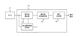
図1に示すように、操作入力装置は、カメラ5と、操作認識処理部10とを含む。カメラ5は、使用者(自動車の運転者)が、運転操作するハンドルの周辺を撮影する位置に固定して設置される。図2は、カメラ5の設置状態を模式的に示す。図2は、運転者が運転席に座ってハンドル2を握っている状態を側方から見た図である。
As shown in FIG. 1, the operation input device includes a
カメラ5の設置場所は、運転席の頭上の正面前方のサンバイザー付近が好ましい。これにより、カメラ5は、運転席付近のハンドル(ステアリング)2、ダッシュボード3、左右のレバー4(図4(A)を参照)などを含む領域を撮影し、その撮影画像を操作認識処理部10へ出力する。車両の運転中に運転者はハンドル2を操作するため、運転者の手や指なども撮影画像に含まれることになる。なお、本実施例では、運転席にあるハンドル2は、多くの車種の自動車で同じような形状、大きさ、配置であり、黒色又は黒色に近い色であると想定する。
The installation location of the
本実施例では、カメラ5は、距離計測カメラ、赤外線カメラ、ステレオカメラ等の特殊なものではなく、通常のカメラとし、例えば秒間30フレームを撮影できるものとする。ただし、カメラ5には、通常は設けられていることが多い赤外線カットフィルタを設けない。また、カメラ5の近傍に補助光の赤外線照射装置を設けて、夜間はハンドル2の付近に赤外線を照射する。これにより、夜間でも使用者の手元周辺をカメラ5で撮影できるようにする。
In this embodiment, the
操作認識処理部10は、カメラ5が撮影した映像(秒間30フレームの連続するフレーム画像)を受け取って解析し、ハンドル2の周辺で行われる操作(ジェスチャ)を認識する。そして、操作を認識すると、操作認識処理部10は、操作対象の車載機器に対して、操作信号を出力する。この実施例では、操作認識処理部10は、コンピュータを用いたソフトウェア処理により実現される。
The operation
図1に示すように、操作認識処理部10は、検出基準領域決定部11と、操作物検出部12と、操作物状態推定部13と、操作決定部14と、を備える。
As illustrated in FIG. 1, the operation
検出基準領域決定部11は、カメラ5から入力された撮影画像を解析し、検出基準領域を決定する。これを、「検出基準領域決定処理」という。検出基準領域とは、撮影画像において、利用者による操作入力を認識する際に基準となる領域をいう。
The detection reference
操作物検出部12は、検出基準領域決定処理により決定された検出基準領域に基づいて、利用者が操作入力に使用する操作物(例えば利用者の指や手)を検出する。これを「操作物検出処理」という。
The operation
操作物状態推定部13は、操作物検出処理により検出された操作物の状態を推定する。これを「操作物状態推定処理」と呼ぶ。具体的には、操作物状態推定部13は、利用者の指や手の操作物の形状を推定する。
The operation article
操作決定部14は、操作物状態推定処理により推定された操作物の状態に基づいて、それに対応する操作を決定し、操作信号を出力する。
The
[操作認識処理]
次に、操作認識処理部10により実行される操作認識処理について詳しく説明する。図3は、操作認識処理のフローチャートである。図3に示すように、操作認識処理部10は、検出基準領域決定処理(ステップS11)、操作物検出処理(ステップS12)、操作物状態推定処理(ステップS13)、及び、操作決定処理(ステップS14)を実行する。以下、順に説明する。
[Operation recognition processing]
Next, the operation recognition process executed by the operation
(1.検出基準領域決定処理)
操作認識処理部10の検出基準領域決定部11は、検出基準領域決定処理を行う(ステップS11)。具体的に、検出基準領域決定部11は、まずカメラ5から入力された撮影画像から、実体物としてのハンドル2を検出し、次に、ハンドル2をよりどころとして検出基準領域を決定する。
(1. Detection reference area determination process)
The detection reference
まず、ハンドル2の検出について説明する。運転席上部から見下ろすように設置されるカメラの設置条件と、多くの車種でハンドルが同じような位置・大きさ・形と想定されるという運転席構造とから、ハンドル2の見え方、即ち、撮影画像中でのハンドル2の位置・大きさ・形状は概ね予想できる。ハンドル2を含む撮影画像の例を図4(A)に示す。この例では、撮影画像は、ハンドル2、ダッシュボード3、レバー4などを含んでいる。
First, detection of the
検出基準領域決定部11は、撮影画像からエッジ(輝度勾配)を求め、様々なパラメータの楕円をマッチングすることにより、楕円形状のエッジを検出し、これをハンドル2の外周部と解釈する。具体的に、図4(B)に示すように、検出基準領域決定部11はハンドル2の外周部に相当する楕円2xを検出する。
The detection reference
カメラ5とハンドル2はいずれも固定されているため、ある程度の時間にわたって撮影した撮影画像を重ね合わせれば、日当り・影や運転者の手などの動的要因を取り除いた、ハンドル2の周辺画像を生成できる。ここで、「ある程度の時間」とは、日当りの変化や運転者の手の見え方の偏りが十分少ないと言える程度である。ハンドル2の検出に使用される撮影画像は、数日間で、運転中・運転中以外、様々な方向からの光が当る場合、曇りの場合などの撮影画像を含む。なお、必ずしも全ての時間の撮影画像を重ね合わせる必要はなく、例えば日当たりが変わった時や、運転を始めた時、運転をやめた時などの条件で、フレーム画像を切り出してもよい。
Since both the
また、撮影画像中に複数の楕円が検出されるような場合は、複数の楕円の中から、車が走行している間に比較的長時間にわたって楕円中の同じような位置が隠れて見えることを条件に、ハンドル2の外周部に相当する楕円2xを選択するようにしてもよい。これは、運転者の手が長時間にわたってハンドル2の同じような位置を握っていることを想定した条件である。例えば、ダッシュボード3の境界からハンドル2に似た半円状のエッジが検出されたとしても、ダッシュボード3に対して、ハンドル2のように運転者が長時間にわたって手を添えていることはないので、その半円状のエッジはハンドル候補から除外することができる。
In addition, when multiple ellipses are detected in the captured image, the same position in the ellipse appears to be hidden from the multiple ellipses for a relatively long time while the car is running. The
次に、検出基準領域の決定について説明する。上記のようにして検出された、実体物としてのハンドル2の外周部に相当する楕円2xを基準に検出基準領域が決定される。具体的には、図4(C)に示すように、検出されたハンドル2の外周部に相当する楕円2xの上側の所定の範囲の弧から、楕円の内側に向かって所定の幅の円弧状の領域を形成し、これを検出基準領域DAとして決定する。ここで言う「上側」とは、ハンドル2の外周部に相当する楕円2xのうち、運転者がハンドル2の上側と認識する側である。「所定の範囲」は、例えば、楕円2xの真上(時計の12時の位置)から左右にそれぞれ45度の範囲とする。所定の範囲は、操作者がジェスチャ操作する範囲に相当する。また、「所定の幅」は、例えば、楕円2xの短軸の半径の0.2倍とする。所定の幅は、ハンドル2のわっかの幅に相当する。
Next, determination of the detection reference area will be described. The detection reference area is determined based on the
検出基準領域の決定は、カメラ5を設置したとき、ハンドル2の位置を調整するなどしてカメラ5とハンドル2の位置関係が変わったときに行う必要がある。具体的には、位置関係が変化したことをカメラ5の画像から検出したときに検出基準領域の決定を行ってもよい。また、利用者によるスイッチ操作などに応じて、検出基準領域の再決定を行うようにしてもよい。
The determination of the detection reference area needs to be performed when the positional relationship between the
(2.操作物検出処理)
検出基準領域が決まれば、利用者がハンドル2に触れるように指を置いた場合の見え方を、検出基準領域を基準にして想定することができる。即ち、ハンドル2に指を置いた場合の指の向きや指の幅を想定することができる。図5は、ハンドル2に3本の指を置いた状態を模式的に示す。
(2. Operation object detection processing)
If the detection reference area is determined, the appearance when the user puts his / her finger so as to touch the
具体的に、指の向きは検出基準領域DAを横切る方向となる。指の幅は、ハンドル2の見た目の大きさからハンドル2のスケールを想定し、ハンドル2上に指を置いた時の見た目上の指の太さを推定することにより決定できる。また、ハンドル表面は暗い色であるとの想定から、指を置いた場合に指はハンドル2の表面よりも明るく見え、ハンドル2の表面と指領域の境界には急峻な輝度値の変化が線状に存在することも想定できる。なお、ハンドル2が白い色であれば、指を置いた時に指がハンドル2の表面より暗く見えることも想定できる。なお、ここではハンドル2は暗い色との想定で説明を進める。
Specifically, the direction of the finger is a direction across the detection reference area DA. The width of the finger can be determined by assuming the scale of the
操作物検出部12は操作物検出処理を行う(ステップS12)。操作物検出処理は、検出基準領域において操作物(指/手)を検出する。具体的には、操作物検出処理部12は、実体物と操作物との関係により決まる操作物の見え方の制約に基づいて、操作物を検出する。本実施例では、実体物であるハンドル2と、操作物である指/手との関係により決まる指/手の見え方の制約に基づいて、操作物である指/手が検出される。
The operation
1つの例では、操作物の見え方の制約は、実体物上に操作物が位置する状態において、実体物と操作物との間の幾何学的な関係に起因して生じる制約である。「幾何学的な関係」は位置、太さ、向きなどを含む。即ち、実体物としてのハンドル2に対する操作物としての指の位置、太さ、向きなどに基づいて、操作物である指が検出される。
In one example, the restriction on the appearance of the operation article is a restriction caused by a geometric relationship between the entity and the operation article in a state where the operation article is located on the entity. “Geometric relationship” includes position, thickness, orientation, and the like. That is, the finger as the operation object is detected based on the position, thickness, orientation, and the like of the finger as the operation object with respect to the
別の例では、操作物の見え方の制約は、実体物上に操作物が位置する状態において、実体物と操作物のそれぞれの光の反射特性による見え方の差に起因して生じる制約である。本実施例では前述のようにハンドル2は黒色に近い暗い色を有しており、黒色のハンドル2上に位置する、白色に近い(明るい)領域を操作物である指として検出することができる。
In another example, the restriction on the appearance of the operation object is a restriction caused by the difference in the appearance due to the reflection characteristics of the light of the object and the operation object when the operation object is located on the object. is there. In the present embodiment, as described above, the
図6は、操作物検出処理のフローチャートである。まず、操作物検出部12は、撮影画像から検出基準領域DA内の各ピクセルの輝度値を抽出し、各ピクセルにおける輝度値勾配の強度と方向を求めることにより、検出基準領域DAを横切る直線を抽出する(ステップS21)。なお、あるピクセルにおける輝度値勾配とは、そのピクセルを中心としそのピクセルに隣接する複数のピクセルの輝度値が作る勾配をいう。検出基準領域DAを横切る直線の例を図7(A)に示す。
FIG. 6 is a flowchart of the operation article detection process. First, the operation
次に、操作物検出部12は、抽出された1つの直線を構成する複数のピクセルについて、輝度値勾配の強度及び方向を集計する(ステップS22)。そして、その直線を構成する複数のピクセルについて、そのピクセルにおける輝度値勾配の強度が予め決められた所定値よりも強く、かつ、その輝度値勾配の方向がその直線と概ね直交しているものが所定割合以上存在する場合に(ステップS23:Yes)、その直線を操作物の境界候補とする(ステップS24)。操作物の境界候補は、具体的にはハンドル2を横切る指又は手などの操作物の左右の境界線に相当する。
Next, the operation
なお、操作物の境界候補は、検出基準領域DAにおいてその境界候補の左右の領域のいずれが明るくいずれが暗いかにより2種類に区別される。具体的には、ステップS24では、1つの直線が、図7(B)に示すように、左側が暗く右側が明るい左側境界候補31と、左側が明るく右側が暗い右側境界候補32のうちのいずれかであるかが検出される。こうして、ステップS21で抽出された全ての横切る直線についてステップS22〜S24の処理が実行され、境界候補が抽出される。
The boundary candidate of the operation article is classified into two types depending on which one of the left and right areas of the boundary candidate is bright and which is dark in the detection reference area DA. Specifically, in step S24, as shown in FIG. 7B, one straight line is selected from either the
次に、操作物検出部12は、左側境界候補31と右側境界候補32のペアを操作物候補とし、ステップS22〜S25で抽出された全ての境界候補から、全ての操作物候補を特定する(ステップS26)。ここで、操作物候補は、左側境界候補31と右側境界候補が左側からこの順で並んでいるペアを特定する。言い換えると、左側境界候補31と、その右側に位置する右側境界候補32とのペアを特定する。操作物候補は、図7(C)に示すように、2つの境界候補の内側が明るく、外側が暗いという組み合わせであり、暗い色のハンドル2上に置かれた指などの操作物と推測することができる。
Next, the operation
次に、操作物検出部12は、その操作物候補の幅(即ち、明るい部分の幅)が操作物(利用者の指又は手)として適切と考えられる場合、その操作物候補を操作物として検出する(ステップS28)。なお、操作物候補を操作物と決定する条件として、その操作物候補を形成する2つの境界候補がほぼ平行であることを追加してもよい。
Next, if the width of the operation object candidate (that is, the width of the bright portion) is considered appropriate as the operation object (user's finger or hand), the operation
図7(C)の例では操作物候補35、36が存在する。この場合、操作物候補35は一般的な人間の指の幅に相当するので操作物(指)として検出される。一方、操作物候補36は一般的な人間の指の幅より狭いので、操作物(指)として検出されない。 In the example of FIG. 7C, there are operation object candidates 35 and 36. In this case, since the operation object candidate 35 corresponds to the width of a general human finger, it is detected as an operation object (finger). On the other hand, since the operation object candidate 36 is narrower than the width of a general human finger, it is not detected as an operation object (finger).
こうして、全ての操作物候補についてステップS27〜S29の処理が行われると(ステップS29:Yes)、撮影画像に含まれる全ての操作物(指/手)が検出されたこととなる。 In this way, when the processing of steps S27 to S29 is performed for all the operation object candidates (step S29: Yes), all the operation objects (finger / hand) included in the photographed image are detected.
(3.操作物状態推定処理)
次に、操作物状態推定部13は操作物状態推定処理を行う(ステップS13)。操作物状態推定処理は、操作物検出部12が検出した操作物の状態、具体的には指又は手の形状を推定する。操作物の状態は、利用者により入力された操作命令に対応するものである。操作物の状態の推定には2つの方法がある。
(3. Operation object state estimation process)
Next, the operation article
(1)第1の方法
第1の方法は、操作物の状態として、単純に検出された指の情報を使うものである。例えば、操作物状態推定部13は、操作物の状態として、検出された指の本数、即ち操作のためにハンドル2上に出された「指本数」を推定する。この場合、指本数が操作命令に対応することになる。
(1) First Method The first method uses information of a finger that is simply detected as the state of the operation article. For example, the operation article
これに加えて、検出された複数の指の間の距離(指の開き方)、ハンドル2に対する指の位置(例えば、ハンドル2のなす円弧上の何度の位置に指が存在するか)、角度(例えば、ハンドル2の中心と、指を検出した位置のハンドル外周とを結ぶ基準線に対する、指の境界線のなす角度)などを操作命令に対応する操作物の状態として使用してもよい。
In addition to this, the distance between the detected fingers (how to open the finger), the position of the finger with respect to the handle 2 (for example, how many positions on the arc the
なお、操作物状態推定部13は、カメラ5からの撮影画像に含まれる複数のフレーム間で、指などの操作物の位置を対応つける処理も行う。これにより、撮影画像のフレーム間での手の動きを操作物の状態として使用することができる。
The operation article
(2)第2の方法
第2の方法は、操作物の状態として手全体の形状(以下、「手形状」と呼ぶ。)を使用する。例えば図8に示す手形状A〜Dをそれぞれ操作命令に対応付ける。操作物状態推定部13は、操作物検出部12により検出された操作物(手)が手形状A〜Dのいずれかを示しているかを判定する。
(2) Second Method The second method uses the shape of the entire hand (hereinafter referred to as “hand shape”) as the state of the operation article. For example, the hand shapes A to D shown in FIG. The operation object
上述の操作物検出処理では、検出基準領域DA(ハンドル2上)のみで操作物を検出しているので、それだけで手形状を判定することは難しい。例えば、図8に示す手形状Aと手形状Bは、検出基準領域DAにおいてはいずれも図9(B)に示すような検出結果が得られ、両者を区別することは難しい。そのため、手形状を推定するために以下のような処理を行う。 In the above-described operation object detection process, the operation object is detected only in the detection reference area DA (on the handle 2), so that it is difficult to determine the hand shape by itself. For example, the hand shape A and the hand shape B shown in FIG. 8 both have the detection results shown in FIG. 9B in the detection reference area DA, and it is difficult to distinguish them. Therefore, the following processing is performed to estimate the hand shape.
まず、操作物状態推定部13は、判定したい手形状の中から、現在、検出基準領域DA上で検出された指形状を含むもののみを抽出する。いま手形状A〜Dのみを使用するものと仮定すると、検出基準領域DA上で検出した操作物の形状が図9(a)の形状であれば、検出された操作物の手形状は手形状Cか手形状Dと推定することができ、手形状A及び手形状Bを除外することができる。
First, the operation article
次に、操作物状態推定部13は、検出基準領域DA上で検出した操作物の見え方の特徴を抽出する。具体的には、操作物状態推定部13は、色情報(肌の色)を抽出する。色によって手を検出する方法は、外光などの撮影環境によって肌色の見え方が変わる場合があるので、様々な環境下で必ずしも安定して利用できる方法ではない。しかし、この場合は、操作物検出部12が色情報よりも適切な別の条件、即ち、検出基準領域DAにおける操作物(指/手)の見え方の制約(具体的には、操作物がハンドル2に重なっているか否かなど)に基づいて操作物を検出しているため、操作物状態推定部13は色情報(肌の色)によって指や手を検出する必要はない。逆に、操作物検出部12により検出された操作物(指/手)の領域から色情報又は輝度情報を抽出すれば、操作物状態推定部13はその時点でのその人物の肌の色の見え方を正確に取得することができる。よって、操作物状態推定部13は、操作物検出部12により操作物(指/手)と検出された領域の色情報又は輝度情報から、その人物の肌色の見え方を取得する。
Next, the operation article
次に、操作物状態推定部13は、取得した色情報又は輝度情報を用いて、撮影画像から検出基準領域DA以外の操作物領域(手領域)を検出する。具体的には、撮影画像中の検出基準領域DA近傍において、先に取得された操作物(指/手)の色と同じ又は近い色又は輝度を有する領域を、操作物領域(手領域)として抽出する。この際、操作物状態推定部13は、検出基準領域DAに操作物(指/手)が存在しない状態での撮影画像との相関を用いて、検出基準領域DA以外の操作物領域を検出することが好ましい。
Next, the operation article
次に、操作物状態推定部13は、検出基準領域内で検出された操作物領域(手領域)と、検出基準領域外で検出された操作物領域(手領域)とを合わせて形成される手形状が、図8に示す手形状A〜Dのいずれかに当てはまるか否かを判定する。この場合、操作物状態推定部13は、単純な重ね合わせによる形状マッチング処理により、手形状を判定することができる。なお、操作物状態推定部13は、検出基準領域内で検出された手領域に対して、検出基準領域外で検出された手領域よりも高い重みをつけて、形状マッチング処理を行うこととしてもよい。
Next, the operation object
こうして、操作物状態推定部13は、第1の方法及び第2の方法を実行することにより、操作命令に対応する操作物の状態(指本数、手形状など)を推定する。
Thus, the operation article
(4.操作決定処理)
次に、操作決定部14は、操作決定処理を行う(ステップS14)。具体的には、操作決定部14は、操作物状態推定部13の推定結果に基づいて、利用者が入力した操作命令を特定する。前述のように、操作物の状態(指本数、手形状など)は、予め決められた操作命令に対応付けられている。よって、操作決定部14は、操作物状態推定部13が推定した操作物の状態に対応する操作命令を、利用者が入力した操作命令と判定し、その操作命令に対応する操作信号を出力する。
(4. Operation decision processing)
Next, the
例えば、操作物状態推定部13が、撮影画像中のあるフレームにおいて、それより前のフレームでは検出されなかった特定の手形状を検出したときに、操作決定部14は、その手形状に対応する操作命令の操作信号を1回出力する。また、操作物である指の位置が前のフレームでの位置に対して変化したことを操作物状態推定部13が検出したときに、操作決定部14はその移動量を操作信号として出力する。例えば、ある時点で指1本がハンドル上の角度0度の位置にあり、次の時点でその指1本がハンドル上の角度3度の位置にあったことを操作物状態推定部13が推定した場合、操作決定部14は、その2つの時点の間で指が左から右に3度に相当する距離移動したものと判定し、その移動量に対応する操作信号を出力する。また、操作状態推定部13が上記の手形状A〜Dのいずれかを検出した場合、操作決定部14はその手形状に対応する操作命令を出力する。
For example, when the operation article
以上のように、操作認識処理部10は、利用者が検出基準領域において、指/手などの操作物を利用して行った操作入力を解釈し、それに対応する操作信号を出力することができる。
As described above, the operation
[ハンドルを利用する利点]
上記の実施例では、車両のハンドルを検出基準領域とし、その上で指又は手を操作物として使用して操作入力を行う。これは以下のような利点を有する。
[Advantages of using a handle]
In the above embodiment, the operation input is performed by using the handle of the vehicle as the detection reference region and using the finger or hand as the operation object. This has the following advantages.
(1)ハンドルは自動車の車種を問わずほぼ形状・位置が決まっており、固定配置されているため、カメラによって検出しやすい。 (1) Since the handle has almost the same shape and position regardless of the type of automobile, and is fixedly arranged, it is easy to detect with a camera.
(2)ハンドル上に検出基準領域を設定することにより、操作物の検出を簡単に行うことができる。これは指の見え方を限定できるためである。即ち、ハンドルをよりどころにすることにより、空中の自由な位置で指差しジェスチャをさせる場合と比較して、利用者が指を出す範囲を限定しやすい。 (2) By setting the detection reference area on the handle, the operation article can be easily detected. This is because the way the fingers are visible can be limited. That is, by using the handle as a base, it is easy to limit the range in which the user puts out the finger, compared to the case where the finger pointing gesture is performed at a free position in the air.
(3)ハンドル上で検出した操作物の情報を確実性の高い情報として使うことにより、ハンドル上以外(ハンドルの外側の領域)に渡る手の形状も高精度で検出することができる。また、ハンドル上で検出した操作物の情報から、操作物の見た目の情報(例えばその時の肌の色あるいは輝度)を抽出し、ハンドル上以外の領域からの操作物領域の検出に使うことができる。これにより、操作物領域の検出精度を上げることができる。 (3) By using the information of the operation article detected on the handle as highly reliable information, it is possible to detect the shape of the hand other than on the handle (region outside the handle) with high accuracy. Further, the appearance information (for example, skin color or brightness at that time) of the operation article is extracted from the information of the operation article detected on the handle, and can be used to detect the operation article region from the area other than the handle. . Thereby, the detection accuracy of the operation article region can be increased.
(4)ハンドル上で利用者がジェスチャを行う方法は、ハンドル脇やシフトレバー付近でジェスチャを行う方法と比較して、ヘッドアップディスプレイ(HUD)のような、前方に像を表示するタイプの表示装置と組み合わせて使用するのに適している。これは、利用者が前方に表示された像を見ながら、その方向を指差す形のインターフェースを実現できるためである。 (4) The method in which the user performs a gesture on the handle is a type of display in which an image is displayed forward, such as a head-up display (HUD), compared to a method in which the user performs a gesture near the handle or near the shift lever. Suitable for use in combination with equipment. This is because it is possible to realize an interface in which the user points in the direction while looking at the image displayed forward.
[変形例]
ハンドル以外に、ダッシュボードの縁、ハンドル周りのレバーなど、ハンドルと同様に見え方が想定できる車内構造物を利用して検出基準領域を設定することができる。
[Modification]
In addition to the steering wheel, the detection reference area can be set by using an in-vehicle structure that can be seen in the same manner as the steering wheel, such as an edge of the dashboard and a lever around the steering wheel.
2 ハンドル
5 カメラ
10 操作認識処理部
11 検出基準領域決定部
12 操作物検出部
13 操作物状態推定部
14 操作決定部
2
Claims (9)
移動体の運転席付近を撮影するカメラにより撮影された撮影画像において、前記運転席付近に設置された実体物の一部分を検出基準領域として決定する決定手段と、
前記撮影画像中の前記検出基準領域において、前記操作入力に使用される操作物によって遮蔽されていない領域に基づき、前記操作物を検出する検出手段と、
検出された前記操作物に基づいて前記操作入力を特定する特定手段と、
を備えることを特徴とする操作入力装置。 An operation input device for performing operation input,
In a captured image captured by a camera that captures the vicinity of a driver's seat of a moving body, a determination unit that determines a part of an entity installed near the driver's seat as a detection reference region;
Detecting means for detecting the operation article based on an area not covered by the operation article used for the operation input in the detection reference area in the captured image;
Specifying means for specifying the operation input based on the detected operation article;
An operation input device comprising:
前記特定手段は、推定された前記操作物の状態に基づいて前記操作入力を特定し、当該操作入力に対応する操作信号を前記装置へ出力することを特徴とする請求項1乃至3のいずれか一項に記載の操作入力装置。 An estimation means for estimating a state of the detected operation article;
4. The apparatus according to claim 1, wherein the specifying unit specifies the operation input based on the estimated state of the operation article, and outputs an operation signal corresponding to the operation input to the apparatus. The operation input device according to one item.
移動体の運転席付近を撮影するカメラにより撮影された撮影画像において、前記運転席付近に設置された実体物の一部分を検出基準領域として決定する決定工程と、
前記撮影画像中の前記検出基準領域において、前記操作入力に使用される操作物によって遮蔽されていない領域に基づき、前記操作物を検出する検出工程と、
検出された前記操作物に基づいて前記操作入力を特定する特定工程と、
を備えることを特徴とする操作入力方法。 An operation input method executed by an operation input device for performing operation input,
In a captured image captured by a camera that captures the vicinity of a driver's seat of a moving object, a determination step of determining a part of an entity installed near the driver's seat as a detection reference region;
In the detection reference region in the captured image, a detection step of detecting the operation article based on an area that is not shielded by the operation article used for the operation input;
A specifying step of specifying the operation input based on the detected operation object;
An operation input method comprising:
移動体の運転席付近を撮影するカメラにより撮影された撮影画像において、前記運転席付近に設置された実体物の一部分を検出基準領域として決定する決定工程と、
前記撮影画像中の前記検出基準領域において、前記操作入力に使用される操作物によって遮蔽されていない領域に基づき、前記操作物を検出する検出工程と、
検出された前記操作物に基づいて前記操作入力を特定する特定工程と、
を前記操作入力装置に実行させることを特徴とする操作入力プログラム。 An operation input program executed by an operation input device that performs operation input,
In a captured image captured by a camera that captures the vicinity of a driver's seat of a moving object, a determination step of determining a part of an entity installed near the driver's seat as a detection reference region;
In the detection reference region in the captured image, a detection step of detecting the operation article based on an area that is not shielded by the operation article used for the operation input;
A specifying step of specifying the operation input based on the detected operation object;
Is executed by the operation input device.
Priority Applications (1)
| Application Number | Priority Date | Filing Date | Title |
|---|---|---|---|
| JP2016070094A JP2016157457A (en) | 2016-03-31 | 2016-03-31 | Operation input device, operation input method and operation input program |
Applications Claiming Priority (1)
| Application Number | Priority Date | Filing Date | Title |
|---|---|---|---|
| JP2016070094A JP2016157457A (en) | 2016-03-31 | 2016-03-31 | Operation input device, operation input method and operation input program |
Related Parent Applications (1)
| Application Number | Title | Priority Date | Filing Date |
|---|---|---|---|
| JP2014516581A Division JP5912177B2 (en) | 2012-05-24 | 2012-05-24 | Operation input device, operation input method, and operation input program |
Related Child Applications (1)
| Application Number | Title | Priority Date | Filing Date |
|---|---|---|---|
| JP2017051677A Division JP2017142820A (en) | 2017-03-16 | 2017-03-16 | Operation input device, operation input method and operation input program |
Publications (1)
| Publication Number | Publication Date |
|---|---|
| JP2016157457A true JP2016157457A (en) | 2016-09-01 |
Family
ID=56826433
Family Applications (1)
| Application Number | Title | Priority Date | Filing Date |
|---|---|---|---|
| JP2016070094A Ceased JP2016157457A (en) | 2016-03-31 | 2016-03-31 | Operation input device, operation input method and operation input program |
Country Status (1)
| Country | Link |
|---|---|
| JP (1) | JP2016157457A (en) |
Cited By (2)
| Publication number | Priority date | Publication date | Assignee | Title |
|---|---|---|---|---|
| CN110235178A (en) * | 2017-03-14 | 2019-09-13 | 欧姆龙株式会社 | Driver status estimating device and driver status estimate method |
| CN117392649A (en) * | 2023-12-11 | 2024-01-12 | 武汉未来幻影科技有限公司 | Identification method and device for indicating operation of vehicle part and processing equipment |
Citations (4)
| Publication number | Priority date | Publication date | Assignee | Title |
|---|---|---|---|---|
| JP2003131785A (en) * | 2001-10-22 | 2003-05-09 | Toshiba Corp | Interface device, operation control method and program product |
| JP2005047412A (en) * | 2003-07-30 | 2005-02-24 | Nissan Motor Co Ltd | Non-contact information input device |
| JP2005178473A (en) * | 2003-12-17 | 2005-07-07 | Denso Corp | Interface for in-vehicle equipment |
| JP2007237919A (en) * | 2006-03-08 | 2007-09-20 | Toyota Motor Corp | Input operation device for vehicle |
-
2016
- 2016-03-31 JP JP2016070094A patent/JP2016157457A/en not_active Ceased
Patent Citations (4)
| Publication number | Priority date | Publication date | Assignee | Title |
|---|---|---|---|---|
| JP2003131785A (en) * | 2001-10-22 | 2003-05-09 | Toshiba Corp | Interface device, operation control method and program product |
| JP2005047412A (en) * | 2003-07-30 | 2005-02-24 | Nissan Motor Co Ltd | Non-contact information input device |
| JP2005178473A (en) * | 2003-12-17 | 2005-07-07 | Denso Corp | Interface for in-vehicle equipment |
| JP2007237919A (en) * | 2006-03-08 | 2007-09-20 | Toyota Motor Corp | Input operation device for vehicle |
Cited By (4)
| Publication number | Priority date | Publication date | Assignee | Title |
|---|---|---|---|---|
| CN110235178A (en) * | 2017-03-14 | 2019-09-13 | 欧姆龙株式会社 | Driver status estimating device and driver status estimate method |
| CN110235178B (en) * | 2017-03-14 | 2023-05-23 | 欧姆龙株式会社 | Driver state estimating device and driver state estimating method |
| CN117392649A (en) * | 2023-12-11 | 2024-01-12 | 武汉未来幻影科技有限公司 | Identification method and device for indicating operation of vehicle part and processing equipment |
| CN117392649B (en) * | 2023-12-11 | 2024-02-27 | 武汉未来幻影科技有限公司 | Identification method and device for indicating operation of vehicle part and processing equipment |
Similar Documents
| Publication | Publication Date | Title |
|---|---|---|
| JP5261554B2 (en) | Human-machine interface for vehicles based on fingertip pointing and gestures | |
| US8378970B2 (en) | Manipulation input device which detects human hand manipulations from captured motion images | |
| US20090167682A1 (en) | Input device and its method | |
| US20140361989A1 (en) | Method and Device for Operating Functions in a Vehicle Using Gestures Performed in Three-Dimensional Space, and Related Computer Program Product | |
| JP2016520946A (en) | Human versus computer natural 3D hand gesture based navigation method | |
| KR20140079162A (en) | System and method for providing a user interface using finger start points shape recognition in a vehicle | |
| KR101490908B1 (en) | System and method for providing a user interface using hand shape trace recognition in a vehicle | |
| JP6671288B2 (en) | Gesture device, operation method thereof, and vehicle equipped with the same | |
| EP2836894A1 (en) | Free hand gesture control of automotive user interface | |
| JP2006285370A (en) | Hand pattern switch device and hand pattern operation method | |
| US9141185B2 (en) | Input device | |
| JP5912177B2 (en) | Operation input device, operation input method, and operation input program | |
| JP6589796B2 (en) | Gesture detection device | |
| JP5382313B2 (en) | Vehicle operation input device | |
| JP2016111509A (en) | Image processing device for vehicle, image processing method for vehicle and program | |
| CN105759955B (en) | Input device | |
| JP6581482B2 (en) | Image recognition device | |
| JP2016157457A (en) | Operation input device, operation input method and operation input program | |
| US20170300120A1 (en) | User interface, means of movement, and methods for recognizing a user's hand | |
| KR100939831B1 (en) | Operating input device for reducing input error and information device operation apparatus | |
| KR101976498B1 (en) | System and method for gesture recognition of vehicle | |
| JP2018147500A (en) | Operation input device, operation input method and operation input program | |
| JP2017142820A (en) | Operation input device, operation input method and operation input program | |
| JP7163649B2 (en) | GESTURE DETECTION DEVICE, GESTURE DETECTION METHOD, AND GESTURE DETECTION CONTROL PROGRAM | |
| JP2020123369A (en) | Operation input device, operation input method and operation input program |
Legal Events
| Date | Code | Title | Description |
|---|---|---|---|
| A131 | Notification of reasons for refusal |
Free format text: JAPANESE INTERMEDIATE CODE: A131 Effective date: 20161011 |
|
| A521 | Request for written amendment filed |
Free format text: JAPANESE INTERMEDIATE CODE: A523 Effective date: 20161130 |
|
| A01 | Written decision to grant a patent or to grant a registration (utility model) |
Free format text: JAPANESE INTERMEDIATE CODE: A01 Effective date: 20170214 |
|
| A045 | Written measure of dismissal of application [lapsed due to lack of payment] |
Free format text: JAPANESE INTERMEDIATE CODE: A045 Effective date: 20170627 |