JP2016151237A - Fuel injection device - Google Patents
Fuel injection device Download PDFInfo
- Publication number
- JP2016151237A JP2016151237A JP2015029805A JP2015029805A JP2016151237A JP 2016151237 A JP2016151237 A JP 2016151237A JP 2015029805 A JP2015029805 A JP 2015029805A JP 2015029805 A JP2015029805 A JP 2015029805A JP 2016151237 A JP2016151237 A JP 2016151237A
- Authority
- JP
- Japan
- Prior art keywords
- fuel
- pressure
- needle
- injection
- fuel injection
- Prior art date
- Legal status (The legal status is an assumption and is not a legal conclusion. Google has not performed a legal analysis and makes no representation as to the accuracy of the status listed.)
- Granted
Links
Images

Classifications
-
- F—MECHANICAL ENGINEERING; LIGHTING; HEATING; WEAPONS; BLASTING
- F02—COMBUSTION ENGINES; HOT-GAS OR COMBUSTION-PRODUCT ENGINE PLANTS
- F02M—SUPPLYING COMBUSTION ENGINES IN GENERAL WITH COMBUSTIBLE MIXTURES OR CONSTITUENTS THEREOF
- F02M45/00—Fuel-injection apparatus characterised by having a cyclic delivery of specific time/pressure or time/quantity relationship
- F02M45/02—Fuel-injection apparatus characterised by having a cyclic delivery of specific time/pressure or time/quantity relationship with each cyclic delivery being separated into two or more parts
- F02M45/04—Fuel-injection apparatus characterised by having a cyclic delivery of specific time/pressure or time/quantity relationship with each cyclic delivery being separated into two or more parts with a small initial part, e.g. initial part for partial load and initial and main part for full load
- F02M45/08—Injectors peculiar thereto
- F02M45/086—Having more than one injection-valve controlling discharge orifices
-
- F—MECHANICAL ENGINEERING; LIGHTING; HEATING; WEAPONS; BLASTING
- F02—COMBUSTION ENGINES; HOT-GAS OR COMBUSTION-PRODUCT ENGINE PLANTS
- F02M—SUPPLYING COMBUSTION ENGINES IN GENERAL WITH COMBUSTIBLE MIXTURES OR CONSTITUENTS THEREOF
- F02M2200/00—Details of fuel-injection apparatus, not otherwise provided for
- F02M2200/46—Valves, e.g. injectors, with concentric valve bodies
-
- F—MECHANICAL ENGINEERING; LIGHTING; HEATING; WEAPONS; BLASTING
- F02—COMBUSTION ENGINES; HOT-GAS OR COMBUSTION-PRODUCT ENGINE PLANTS
- F02M—SUPPLYING COMBUSTION ENGINES IN GENERAL WITH COMBUSTIBLE MIXTURES OR CONSTITUENTS THEREOF
- F02M57/00—Fuel-injectors combined or associated with other devices
- F02M57/02—Injectors structurally combined with fuel-injection pumps
- F02M57/022—Injectors structurally combined with fuel-injection pumps characterised by the pump drive
- F02M57/025—Injectors structurally combined with fuel-injection pumps characterised by the pump drive hydraulic, e.g. with pressure amplification
-
- F—MECHANICAL ENGINEERING; LIGHTING; HEATING; WEAPONS; BLASTING
- F02—COMBUSTION ENGINES; HOT-GAS OR COMBUSTION-PRODUCT ENGINE PLANTS
- F02M—SUPPLYING COMBUSTION ENGINES IN GENERAL WITH COMBUSTIBLE MIXTURES OR CONSTITUENTS THEREOF
- F02M61/00—Fuel-injectors not provided for in groups F02M39/00 - F02M57/00 or F02M67/00
- F02M61/16—Details not provided for in, or of interest apart from, the apparatus of groups F02M61/02 - F02M61/14
- F02M61/18—Injection nozzles, e.g. having valve seats; Details of valve member seated ends, not otherwise provided for
- F02M61/1806—Injection nozzles, e.g. having valve seats; Details of valve member seated ends, not otherwise provided for characterised by the arrangement of discharge orifices, e.g. orientation or size
- F02M61/182—Discharge orifices being situated in different transversal planes with respect to valve member direction of movement
Abstract
Description
本発明は、燃料噴射装置に関する。 The present invention relates to a fuel injection device.
第一噴孔を開閉するアウタニードルと、第二噴孔を開閉するインナニードルとを備え、アウタニードルが所定量上昇すると、インナニードルがアウタニードルと共に上昇する機構を備える燃料噴射弁が知られている(例えば、特許文献1参照。)。 There is known a fuel injection valve that includes an outer needle that opens and closes a first nozzle hole and an inner needle that opens and closes a second nozzle hole, and has a mechanism that raises the inner needle together with the outer needle when the outer needle rises by a predetermined amount. (For example, refer to Patent Document 1).
アウタニードルとインナニードルとを有する一般的な燃料噴射弁では、まずアウタニードルが上昇して第一噴孔から燃料が噴射され、アウタニードルが所定量上昇すると、アウタニードルがインナニードルを押すことでインナニードルが上昇する。インナニードルが上昇すると、第一噴孔及び第二噴孔から燃料が噴射される。その後に、アウタニードルが下降すると、インナニードルも同様に下降する。アウタニードル及びインナニードルが下降してアウタニードルのリフト量が所定量になると、インナニードルが着座して第二噴孔からの燃料噴射が終了し、第一噴孔のみから燃料が噴射される。最後にアウタニードルが着座して第一噴孔からの燃料の噴射が終了する。 In a general fuel injection valve having an outer needle and an inner needle, first, the outer needle rises and fuel is injected from the first injection hole. When the outer needle rises by a predetermined amount, the outer needle pushes the inner needle. The inner needle rises. When the inner needle rises, fuel is injected from the first nozzle hole and the second nozzle hole. Thereafter, when the outer needle is lowered, the inner needle is similarly lowered. When the outer needle and the inner needle descend and the lift amount of the outer needle reaches a predetermined amount, the inner needle is seated, the fuel injection from the second injection hole is completed, and the fuel is injected only from the first injection hole. Finally, the outer needle is seated and the fuel injection from the first nozzle hole is completed.
上記のような機構を有する燃料噴射弁では、インナニードルが着座した後で且つ燃料噴射の終了前に第一噴孔のみから燃料を噴射する期間がある。この期間は、第一噴孔及び第二噴孔から燃料が噴射されるときと比較して、単位時間当たりの燃料噴射量(すなわち、噴射率)が小さくなる。ここで、ニードルを1本のみ有する燃料噴射弁では、噴射率が低下するのはニードルが着座する直前の比較的短い期間だけである。一方、上記のアウタニードルとインナニードルとを有する燃料噴射弁では、インナニードルが着座する直前からアウタニードルが着座するまでの期間において噴射率が低下する。このため、燃料の噴射が完了するまでにより長い時間を要する。ここで、燃料噴射の期間が長くなると、燃料噴射の終期には、燃料噴射の初期に噴射された燃料が燃焼して高温且つ高圧となった気筒内に燃料が噴射されるようになるため、燃料と空気との混合が不十分のうちに燃焼が始まってしまうので、スモークが発生しやすくなる。 In the fuel injection valve having the above-described mechanism, there is a period in which fuel is injected only from the first injection hole after the inner needle is seated and before the end of fuel injection. During this period, the fuel injection amount per unit time (that is, the injection rate) is smaller than when fuel is injected from the first injection hole and the second injection hole. Here, in the fuel injection valve having only one needle, the injection rate decreases only in a relatively short period immediately before the needle is seated. On the other hand, in the fuel injection valve having the outer needle and the inner needle described above, the injection rate decreases in the period from immediately before the inner needle is seated to the outer needle is seated. For this reason, it takes a longer time to complete the fuel injection. Here, if the fuel injection period is long, at the end of the fuel injection, the fuel injected at the initial stage of the fuel injection burns and is injected into the cylinder that has become high temperature and high pressure. Smoke is likely to occur because the combustion starts while the mixing of fuel and air is insufficient.
本発明は、上記したような問題点に鑑みてなされたものであり、その目的は、時間差で閉じる複数の噴孔を有する燃料噴射弁において、燃焼状態を改善することにある。 The present invention has been made in view of the above-described problems, and an object thereof is to improve a combustion state in a fuel injection valve having a plurality of injection holes that close with a time difference.
上記課題を解決するために本発明に係る燃料噴射装置は、ニードルの動作量が大きいときには小さいときよりも総噴孔面積が大きくなる燃料噴射弁と、前記総噴孔面積が大きい状態から小さい状態へ変わるときに、前記総噴孔面積が大きい状態のときよりも小さい状態のときの方が燃料の圧力が大きくなるように燃料の圧力を増加する制御装置と、を備える。 In order to solve the above-described problem, a fuel injection device according to the present invention includes a fuel injection valve having a larger total nozzle hole area when the needle operation amount is large, and a state in which the total nozzle hole area is small from a large state. And a control device that increases the fuel pressure so that the fuel pressure increases when the total nozzle hole area is smaller than when the total nozzle hole area is large.
総噴孔面積が大きい状態から小さい状態へ変わることにより噴射率が低下し得るが、こ
のときに噴射される燃料の圧力を増加させることにより、実際に噴射率が低下することを抑制できる。すなわち、噴射率が高い状態を維持することができる。その結果、燃料噴射量の総量を変化させずに、ニードルを下降させる時期を早くすることができるので、燃料の噴射期間を短縮することができる。このため、スモークが発生することを抑制できる。また、燃料の圧力の増加により、燃料の微粒化を促進させることもできるので、燃焼を促進させることができ、これによっても、スモークの発生を抑制できる。なお、燃料の圧力は、ニードルの動作量に連動して機械的に増加させてもよいが、以下のようにしてもよい。
Although the injection rate can be reduced by changing the total nozzle hole area from a large state to a small state, it is possible to suppress the actual reduction in the injection rate by increasing the pressure of the fuel injected at this time. That is, it is possible to maintain a high injection rate. As a result, the timing for lowering the needle can be advanced without changing the total amount of fuel injection, so the fuel injection period can be shortened. For this reason, it is possible to suppress the occurrence of smoke. Further, since the atomization of the fuel can be promoted by increasing the pressure of the fuel, the combustion can be promoted, and the generation of smoke can be suppressed also by this. The fuel pressure may be mechanically increased in conjunction with the operation amount of the needle, but may be as follows.
また、前記燃料噴射弁が、第一噴孔と、第二噴孔と、該第一噴孔を開閉する第一ニードルと、該第二噴孔を開閉し該第一ニードルのリフト量が第一所定量以上のときに該第一ニードルと共にリフトする第二ニードルと、を有する燃料噴射装置において、前記燃料噴射弁から噴射される燃料の圧力を変化させる圧力変化部をさらに備え、前記制御装置は、前記第一ニードルのリフト量が前記第一所定量以上になった後、前記第一ニードル及び前記第二ニードルが下降して、前記第二ニードルのリフト量が、第二所定量になるときに、前記圧力変化部による燃料の圧力の増加を開始することもできる。 The fuel injection valve includes a first injection hole, a second injection hole, a first needle that opens and closes the first injection hole, and opens and closes the second injection hole. And a second needle that lifts together with the first needle when the amount exceeds a predetermined amount, further comprising a pressure changing unit that changes a pressure of the fuel injected from the fuel injection valve, After the lift amount of the first needle becomes equal to or greater than the first predetermined amount, the first needle and the second needle are lowered, and the lift amount of the second needle becomes the second predetermined amount. Sometimes, it is possible to start increasing the fuel pressure by the pressure changing unit.
第二噴孔の燃料の噴射率の低下開始時から、噴射される燃料の圧力を増加させることにより、実際に噴射率が低下することを抑制できる。すなわち、噴射率が高い状態を維持することができる。その結果、燃料噴射量の総量を変化させずに、第一ニードル及び第二ニードルを下降させる時期を早くすることができるので、燃料の噴射期間を短縮することができる。このため、スモークが発生することを抑制できる。また、燃料の圧力の増加により、燃料の微粒化を促進させることもできるので、燃焼を促進させることができ、これによっても、スモークの発生を抑制できる。第一所定量は、第二ニードルが上昇を開始するときの第一ニードルのリフト量である。第一ニードルのリフト量が第一所定量以上であれば、第一噴孔及び第二噴孔から燃料が噴射され、第一ニードルのリフト量が第一所定量未満であれば、第一噴孔のみから燃料が噴射される。 By actually increasing the pressure of the injected fuel from the start of the decrease in the injection rate of the fuel in the second nozzle hole, it is possible to suppress the actual decrease in the injection rate. That is, it is possible to maintain a high injection rate. As a result, the timing for lowering the first needle and the second needle can be advanced without changing the total amount of fuel injection, so the fuel injection period can be shortened. For this reason, it is possible to suppress the occurrence of smoke. Further, since the atomization of the fuel can be promoted by increasing the pressure of the fuel, the combustion can be promoted, and the generation of smoke can be suppressed also by this. The first predetermined amount is the lift amount of the first needle when the second needle starts to rise. If the lift amount of the first needle is greater than or equal to the first predetermined amount, fuel is injected from the first nozzle hole and the second nozzle hole, and if the lift amount of the first needle is less than the first predetermined amount, the first injection is performed. Fuel is injected only from the holes.
また、前記第二所定量は、仮に燃料の圧力を増加しないと前記第二噴孔から噴射される燃料の噴射率が低下するリフト量であってもよい。第二所定量は、第二ニードルと弁座との間の燃料の通路の断面積が、第二噴孔の断面積と等しくなるときの第二ニードルのリフト量ともいえる。 Further, the second predetermined amount may be a lift amount at which the injection rate of the fuel injected from the second injection hole decreases unless the fuel pressure is increased. The second predetermined amount can be said to be the lift amount of the second needle when the cross-sectional area of the fuel passage between the second needle and the valve seat becomes equal to the cross-sectional area of the second injection hole.
また、前記制御装置は、前記第一ニードルのリフト量が前記第一所定量以上になった後、前記第一ニードル及び前記第二ニードルが下降して、前記第二ニードルのリフト量が前記第二所定量になるときに、前記第一噴孔及び前記第二噴孔を合わせた燃料の噴射率が変化しないように、前記圧力変化部により燃料の圧力を増加させることができる。 Further, the control device is configured such that after the lift amount of the first needle becomes equal to or greater than the first predetermined amount, the first needle and the second needle are lowered, and the lift amount of the second needle is the first lift amount. The fuel pressure can be increased by the pressure changing unit so that the fuel injection rate of the first nozzle hole and the second nozzle hole does not change when the second predetermined amount is reached.
ここで、第二ニードルが下降することにより、燃料の噴射率が低下し得るときに、燃料の圧力を増加させることにより、噴射率の低下を抑制できる。このときに、第一噴孔及び第二噴孔を合わせた燃料の噴射率が変化しないように燃料の圧力を調整することにより、燃料の圧力を増加させる前後においてトルク変動が発生することを抑制できる。 Here, when the injection rate of the fuel can be reduced by the lowering of the second needle, the decrease in the injection rate can be suppressed by increasing the pressure of the fuel. At this time, by adjusting the fuel pressure so that the fuel injection rate of the first nozzle hole and the second nozzle hole does not change, it is possible to suppress the occurrence of torque fluctuation before and after the fuel pressure is increased. it can.
本発明によれば、時間差で閉じる複数の噴孔を有する燃料噴射弁において、燃焼状態を改善することができる。 According to the present invention, it is possible to improve the combustion state in a fuel injection valve having a plurality of injection holes that close with a time difference.
以下に図面を参照して、この発明を実施するための形態を、実施例に基づいて例示的に詳しく説明する。ただし、この実施例に記載されている構成部品の寸法、材質、形状、その相対配置などは、特に記載がない限りは、この発明の範囲をそれらのみに限定する趣旨のものではない。 DESCRIPTION OF EMBODIMENTS Hereinafter, embodiments for carrying out the present invention will be exemplarily described in detail with reference to the drawings. However, the dimensions, materials, shapes, relative arrangements, and the like of the components described in this embodiment are not intended to limit the scope of the present invention only to those unless otherwise specified.
<実施例1>
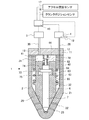
図1は、本実施例における燃料噴射弁1の断面図である。燃料噴射弁1は、例えば、ディーゼルエンジン等の内燃機関に適用される。燃料噴射弁1は、気筒毎に設けられ、気筒内に燃料を直接噴射する。なお、本実施例においては、燃料噴射弁1を簡潔に表示するため、一部の構成要素の表示を省略している。
<Example 1>
FIG. 1 is a cross-sectional view of a
燃料噴射弁1は、ノズル部2、背圧部3、増圧部4を備えている。背圧部3及び増圧部4には、図示しないコモンレール等から燃料が供給される。そして、背圧部3、及び増圧部4では、夫々、圧電素子等を利用して燃料の圧力が調整される。なお、背圧部3及び増圧部4は、ノズル部2の内部に設けられていてもよく、ノズル部2の外部に設けられていてもよい。増圧部4には、燃料の圧力を検出する圧力センサ19が設けられている。圧力センサ19は、増圧部4から流出する燃料の圧力を検出し、この燃料の圧力は燃料噴射弁1から噴射される燃料の圧力と等しい。本実施例に係る増圧部4は、所定の比率で燃料の圧力を増加させる。なお、背圧部3及び増圧部4の構造は周知であるため説明を省略する。本実施例においては増圧部4が、本発明における圧力変化部に相当する。
The
ノズル部2は、プレート11およびノズルボディ21を備えている。ノズルボディ21は、プレート11側の一端が開口し、他端が閉じている円筒形状の部材であり、この中には、アウタニードル6、インナニードル7、シリンダ42、アウタスプリング43、およびインナスプリング44が備わる。ノズルボディ21の上端部には、プレート11が図示しないリテーニングナット等で固定されている。
The
また、ノズルボディ21の底部には、アウタ噴孔22と、インナ噴孔23が形成されている。アウタ噴孔22およびインナ噴孔23は、共にノズルボディ21の中心軸を中心とした、径の異なる同心円に沿って複数個形成されている。アウタ噴孔22は、インナ噴孔23が形成されているよりもノズルボディ21の中心軸側から見て外側に形成されている。なお、本実施例においてはアウタ噴孔22が、本発明における第一噴孔に相当し、インナ噴孔23が、本発明における第二噴孔に相当する。
Further, an
アウタニードル6とインナニードル7は、これらの噴孔側端部でそれぞれアウタ噴孔22、インナ噴孔23の開放、閉塞を行う弁体である。アウタニードル6及びインナニードル7の中心軸は、ノズルボディ21の中心軸と同軸上にある。アウタニードル6は、その中心軸の周りに中空部を有する円筒状の弁体である。インナニードル7は、アウタニード
ル6の中空部に該アウタニードル6の中心軸方向に移動可能に挿入される円柱状の弁体である。なお、本実施例においてはアウタニードル6が、本発明における第一ニードルに相当し、インナニードル7が、本発明における第二ニードルに相当する。
The
アウタニードル6の軸方向で噴孔22,23側とは反対側(以下、反噴孔側という。)には、アウタニードル6の移動を案内する円筒状のシリンダ42が配置されている。シリンダ42の反噴孔側端部は、プレート11の壁面41に当接している。シリンダ42の噴孔側端部とアウタニードル6との間には、アウタニードル6を噴孔方向に付勢するアウタスプリング43が配置されている。プレート11の壁面41とインナニードル7との間には、インナニードル7を噴孔方向に付勢するインナスプリング44が配置されている。
A
ノズルボディ21内には、いくつかの空間が形成される。ノズルボディ21の内壁とアウタニードル6の側壁との間には、ノズル室32が形成される。このノズル室32の一端は、プレート11に形成されている通路12を介して燃料供給通路28の一端に通じており、該このノズル室32の他端は、アウタ噴孔22及びインナ噴孔23に通じている。燃料供給通路28の他端は、増圧部4に接続されている。燃料供給通路28を通じてノズル室32に導入される高圧燃料は、アウタ噴孔22およびインナ噴孔23から噴射される。
Several spaces are formed in the
また、ノズルボディ21の反噴孔側端部には、アウタ反噴孔側受圧面62、インナ反噴孔側受圧面72、壁面41、およびシリンダ42の内壁によって背圧室31が区画されている。この背圧室31は、プレート11に形成されている通路13を介して燃料通路30の一端に通じている。この燃料通路30の他端は、背圧部3に接続されている。背圧部3を駆動させることで、背圧室31内の圧力を調整することができる。ここで、背圧部3に駆動信号を入力すると、背圧室31内の圧力が低下する。これにより、両反噴孔側受圧面62、72にかかる力が低下し、アウタニードル6を反噴孔側へ引き寄せる。
Further, the
アウタニードル6の内壁には、環状の溝63が形成されている。この溝63は、内周面がアウタニードル6の中心軸方向と平行となるように、そして、噴孔側及び反噴孔側の内壁面がアウタニードル6の中心軸方向と直交するように形成されている。この溝63の反噴孔側の壁面を溝上端面64と称し、噴孔側の壁面を溝下端面65と称する。
An
一方、インナニードル7には、該インナニードル7と同軸で且つ該インナニードル7よりも径の大きな円柱形状の突起73が形成されている。この突起73の反噴孔側の端面を突起上端面74と称し、噴孔側の端面を突起下端面75と称する。
On the other hand, the
溝上端面64と突起上端面74とは対向配置され、溝下端面65と突起下端面75とは対向配置されている。また、突起73の高さ、すなわち突起上端面74と突起下端面75との距離は、溝上端面64から溝下端面65までの距離よりも短くなっている。
The groove
図1に示すように、両ニードル6、7が両噴孔22、23を閉じている状態の場合には、突起上端面74と溝上端面64との間、及び、突起下端面75と溝下端面65との間には、隙間が形成されている。
As shown in FIG. 1, when both the
アウタ噴孔22及びインナ噴孔23周辺のノズルボディ21内壁面には、アウタニードル6及びインナニードル7の夫々が着座する弁座26が形成されている。図1は、アウタニードル6及びインナニードル7が着座している状態を示しており、アウタ噴孔22がアウタニードル6により閉塞され、インナ噴孔23がインナニードル7により閉塞されている。
A
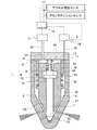
アウタニードル6及びインナニードル7の動作について説明する。図2は、アウタ噴孔
22から燃料が噴射され、インナ噴孔23からは燃料が噴射されていない状態での燃料噴射弁1を示している。図3は、アウタ噴孔22及びインナ噴孔23から燃料が噴射されている状態での燃料噴射弁1を示している。
The operation of the
背圧部3に駆動信号を入力すると、背圧室31内の圧力が低下して、アウタ反噴孔側受圧面62にかかる圧力が低下する。これにより、噴孔方向の力よりも反噴孔方向の力が大きくなり、アウタニードル6は、反噴孔方向に移動する。その結果、アウタニードル6は弁座26から離れ、アウタ噴孔22から高圧燃料が噴射される(図2)。
When a drive signal is input to the
アウタニードル6が反噴孔方向にさらに移動すると、溝下端面65と突起下端面75とが当接する。その後にインナニードル7は、アウタニードル6と共に、壁面41方向に移動する。このとき、インナニードル7は、弁座26から離れるので、インナ噴孔23からも高圧燃料が噴射される(図3)。したがって、本実施例に係る燃料噴射弁1は、ニードルの動作量が大きいときには小さいときよりも総噴孔面積が大きくなる燃料噴射弁といえる。
When the
次に、背圧部3への駆動信号の入力を終了すると、背圧室31内の圧力が高くなり、アウタ反噴孔側受圧面62及びインナ反噴孔側受圧面72にかかる圧力が上昇する。したがって、アウタニードル6及びインナニードル7が共に噴孔方向に移動する。その後、先ずインナニードル7が弁座26に着座してインナ噴孔23から燃料噴射が停止され(図2)、その後に、アウタニードル6が弁座26に着座してアウタ噴孔22からの燃料噴射が停止される(図1)。
Next, when the input of the drive signal to the
以上述べたように構成された燃料噴射弁1には、該燃料噴射弁1を制御するための電子制御ユニットであるECU10が併設されている。このECU10は、内燃機関の運転条件や運転者の要求に応じて燃料噴射弁1を制御する。ECU10には、上記センサの他、運転者がアクセルペダルを踏み込んだ量に応じた電気信号を出力し機関負荷を検知するアクセル開度センサ17、および機関回転速度を検知するクランクポジションセンサ18が電気配線を介して接続され、これら各種センサの出力信号がECU10に入力される。一方、ECU10には、背圧部3及び増圧部4が電気配線を介して接続されており、該ECU10によりこれらの機器が制御される。なお、ECU10は、燃料噴射弁1の背圧部3及び増圧部4を制御しているが、以下では、ECU10が燃料噴射弁1を制御しているものとする。ECU10は、増圧部4を操作することにより、燃料の圧力を調整する。さらに、ECU10は、背圧部3を操作することにより、アウタニードル6及びインナニードル7を上昇若しくは下降させる。なお、本実施例では、アウタニードル6及びインナニードル7の反噴孔側への移動を「上昇」といい、噴孔側への移動を「下降」という。また、アウタニードル6及びインナニードル7の着座位置からの反噴孔側への移動量を「リフト量」という。
The
このように構成された燃料噴射弁1では、アウタニードル6のリフト量と、インナニードル7のリフト量と、には相関関係があり、アウタニードル6のリフト量に応じてインナニードル7のリフト量が決まる。したがって、インナニードル7をアウタニードル6から独立して操作することはできない。このため、燃料噴射を終了させるときには、先ずインナニードル7が着座し、その後にアウタニードル6が着座することになるため、アウタ噴孔22のみから燃料が噴射される期間が存在する。
In the
ここで噴射期間が長くなると、スモークが発生する虞がある。すなわち、噴射期間が長くなると、噴射期間の終わり近くでは初期の燃焼により気筒内がすでに高温高圧の状態となっているため、燃料を噴射後に直ぐに燃焼が始まってしまい、空気との混合が不十分な状態で燃料が燃焼するため、スモークが発生しやすい。このような理由から、インナニー
ドル7が着座した後、アウタニードル6が着座するまでの間は、スモークが発生し易い。
Here, if the injection period is long, smoke may be generated. In other words, when the injection period becomes longer, the cylinder is already in a high-temperature and high-pressure state due to initial combustion near the end of the injection period, so combustion starts immediately after fuel injection and mixing with air is insufficient. Smoke is likely to occur because the fuel burns in a stable state. For this reason, smoke is likely to occur after the
一方、本実施例においては、インナニードル7の下降に伴って燃料の噴射率が低下することを抑制するように、増圧部4により燃料の圧力を増加させる。噴射率の低下を抑制することで、燃料噴射量の総量を変えずに燃料の噴射期間を短くすることができるため、空気と燃料との混合が不十分な状態での燃焼を抑制することができるので、スモークの発生を抑制することができる。
On the other hand, in this embodiment, the pressure of the fuel is increased by the pressure-intensifying unit 4 so as to suppress the fuel injection rate from being lowered as the
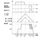
図4は、本実施例に係る噴射制御時の噴射信号、増圧部駆動信号、増加圧力、ニードルリフト量、燃料の噴射率の推移を示したタイムチャートである。噴射信号は、背圧部3の駆動信号であり、背圧部3に入力される信号である。この信号が送られているときに背圧部3が背圧室31内の圧力を低下させる。増圧部駆動信号は、増圧部4の駆動信号であり、増圧部4へ駆動信号が入力されているときに増圧部4が燃料の圧力を増加させる。増圧部4は、図示しないコモンレールから送られてくる燃料に対して増圧を行う。増加圧力は、コモンレールの圧力からの増加量を示している。ニードルリフト量における実線はアウタニードル6のリフト量を示し、一点鎖線はインナニードル7のリフト量を示している。噴射率は、アウタ噴孔22及びインナ噴孔23を合わせた燃料の単位時間当たりの噴射量を示している。なお、噴射率における一点鎖線は、本実施例と同じ期間に背圧部3を駆動させた場合で、且つ、増圧部4による燃料の圧力の増加を実施しない場合を示している。
FIG. 4 is a time chart showing the transition of the injection signal, the pressure-intensifying unit drive signal, the increase pressure, the needle lift amount, and the fuel injection rate during the injection control according to the present embodiment. The injection signal is a drive signal for the
図4において、T1は、噴射信号の始点である。T2は、アウタ噴孔22からの燃料の噴射が開始される時点、すなわち、アウタニードル6が上昇を開始する時点である。T3は、アウタニードル6と弁座26との間の燃料の通路の断面積が、アウタ噴孔22の断面積と等しくなる時点である。このときのアウタ噴孔22の断面積は、複数のアウタ噴孔22の全ての断面積を合わせた値である。T4は、インナ噴孔23からの燃料噴射が開始される時点、すなわち、インナニードル7が上昇を開始する時点である。このT4におけるアウタニードル6のリフト量が、本発明における第一所定量に相当する。T5は、インナニードル7と弁座26との間の燃料の通路の断面積が、インナ噴孔23の断面積と等しくなる時点である。このときのインナ噴孔23の断面積は、複数のインナ噴孔23の全ての断面積を合わせた値である。
In FIG. 4, T1 is the starting point of the injection signal. T2 is the time when the fuel injection from the
T6は、噴射信号の入力が終了する時点である。T7は、アウタニードル6及びインナニードル7が下降を開始する時点である。T8は、インナニードル7と弁座26との間の燃料の通路の断面積が、インナ噴孔23の断面積と等しくなる時点であり、増圧部4により燃料の増圧を実施しない場合に、噴射率が低下する時点である。また、T8は、増圧部4による燃料の増圧を開始する時点である。このT8におけるインナニードル7のリフト量が、本発明における第二所定量に相当する。T9は、インナ噴孔23からの燃料噴射が終了する時点、すなわち、インナニードル7が弁座26に着座する時点である。T10は、増圧部4への駆動信号の入力が終了する時点である。T11はアウタ噴孔22からの燃料噴射が終了する時点、すなわち、アウタニードル6が弁座26に着座する時点を示している。これら、T1からT11の各時点は、燃料噴射量及び燃料圧力に応じて決まる。
T6 is the time when the input of the injection signal ends. T7 is a time point when the
T1においてECU10から燃料噴射弁1へ噴射信号が入力されると、T2においてアウタニードル6が上昇を開始する。T1からT2の期間は、アウタニードル6の応答遅れといえる。T2からT3の期間は、アウタニードル6のニードルリフト量が増加するにしたがって、噴射率が増加していく。T3からT4の期間は噴射率がDQ1で一定となる。このときには、アウタニードル6は上昇を続けているものの、アウタ噴孔22の断面積によって噴射率が決まってしまうため、噴射率は増加しない。そして、T4においてアウタニードル6のリフト量が第一所定量になると、溝下端面65と突起下端面75とが当接し、インナニードル7が上昇を開始する。T4からT5の期間は、インナニードル7のニー
ドルリフト量が増加するにしたがって、噴射率が増加していく。
When an injection signal is input from the
その後、T5からは噴射率がDQ2で略一定となる。このときには、アウタニードル6及びインナニードル7が上昇を続けているものの、アウタ噴孔22及びインナ噴孔23の断面積によって噴射率が決まってしまうため、T8までは噴射率が略一定となっている。
Thereafter, the injection rate becomes substantially constant at DQ2 from T5. At this time, although the
T6において噴射信号が終了しても、アウタニードル6及びインナニードル7はリフト状態にあるため、噴射率はすぐには低下しない。噴射信号の終了によりT7においてアウタニードル6及びインナニードル7が下降を始める。T6からT7の期間は、噴射信号の終了から実際にアウタニードル6及びインナニードル7が下降を始めるまでの応答遅れといえる。このときには、アウタ噴孔22及びインナ噴孔23の断面積によって噴射率が決まっているため、アウタニードル6及びインナニードル7が下降してはいるが、噴射率は減少しない。
Even when the injection signal ends at T6, the
T8は、仮に燃料の圧力を増加させないと、噴射率が低下を始める時点である。T8からT9までの期間は、インナ噴孔23は開いており、且つ、インナ噴孔23の断面積よりも、インナニードル7と弁座26との間の燃料の通路の断面積のほうが小さい。このため、インナ噴孔23からの燃料の噴射率が、インナ噴孔23の断面積ではなく、インナニードル7と弁座26との間の燃料の通路の断面積によって変化し得る。したがって、T8以降はインナニードル7の下降に応じてインナ噴孔23からの燃料の噴射率が低下し得るが、本実施例では、インナ噴孔23からの燃料の噴射率が低下を開始する時点であるT8から増圧部4を駆動させることで燃料の圧力を増加させている。すなわち、T8の時点から増圧部4に駆動信号が入力され、該増圧部4により燃料の圧力が増加される。これにより、燃料の圧力の増加分である「増加圧力」がT8からT9の期間において徐々に増加している。
T8 is a point in time when the injection rate starts to decrease unless the fuel pressure is increased. During the period from T8 to T9, the
T9は、インナニードル7が弁座26に着座する時点である。すなわち、T9においてインナ噴孔23からの燃料噴射が終了する。T8からT9の期間は、インナニードル7と弁座26との間の燃料の通路の断面積の減少に応じて燃料の圧力が高くなる期間であり、図4においては結果として噴射率がDQ2で略一定となっている。なお、T8からT9の期間において噴射率の下降に応じて増加圧力が上昇するように、増圧部4を構成しておいてもよい。すなわち、増圧部4に駆動信号が入力されてから燃料の圧力が徐々に増加していくときに、噴射率の下降を補うように燃料の圧力が増加するように、増圧部4の仕様を決定してもよい。
T9 is the time when the
T9からT10の期間は、アウタ噴孔22の断面積よりも、アウタニードル6と弁座26との間の燃料の通路の断面積のほうが大きくなっている。このため、アウタ噴孔22からの燃料の噴射率は一定となる。このときに、図4においては、増加圧力が一定となっている。なお、T9からT10の期間に増加圧力が一定となるように、増圧部4の仕様を決定してもよい。
During the period from T9 to T10, the cross-sectional area of the fuel passage between the
T10において増圧部4への駆動信号が停止される。したがって、T10から増加圧力が下降する。ここで、増加圧力が0となるときに、アウタニードル6と弁座26との間の燃料の通路の断面積が、アウタ噴孔22の断面積と等しくなるように、T10を決定してもよい。そして、T10からT11の期間は、アウタニードル6のリフト量の減少または燃料圧力の減少により、アウタ噴孔22からの噴射率が下降する。そして、T11においてアウタニードル6が弁座26に着座することで燃料噴射弁1からの燃料噴射が終了する。
At T10, the drive signal to the pressure increasing unit 4 is stopped. Therefore, the increase pressure decreases from T10. Here, even if T10 is determined so that the cross-sectional area of the fuel passage between the
図4に示した噴射率においては、T8から燃料の圧力を増加させた場合(実線の場合)
には、燃料の圧力を増加させない場合(一点鎖線の場合)よりも、ハッチングを施した部分の面積A1の分だけ燃料の噴射量が多くなる。したがって、従来のように燃料の圧力を増加させない場合には、本願と同じ量の燃料を噴射するために、噴射信号をより長く入力する必要がある。このため、燃料の噴射期間が長くなってしまう。一方、本実施例では、燃料噴射率の低下を抑制することで燃料の噴射期間を短縮することができる。
In the injection rate shown in FIG. 4, when the fuel pressure is increased from T8 (solid line)
Therefore, the amount of fuel injection is increased by the area A1 of the hatched portion, compared with the case where the fuel pressure is not increased (in the case of the one-dot chain line). Therefore, when the fuel pressure is not increased as in the prior art, it is necessary to input the injection signal longer in order to inject the same amount of fuel as in the present application. For this reason, the fuel injection period becomes long. On the other hand, in this embodiment, the fuel injection period can be shortened by suppressing the decrease in the fuel injection rate.
なお、図4に示した例では、T10において増圧部4への駆動信号の入力を停止させているが、これに代えて、他の時期に増圧部4への駆動信号の入力を停止させてもよい。例えば、アウタニードル6が弁座26に着座する時点T11まで、増圧部4へ駆動信号を入力してもよいし、T11において増加圧力が0となるように、増圧部4へ駆動信号を入力してもよい。また、T8よりも後で且つT10よりも前に増圧部4への駆動信号を停止させてもよい。これらの場合であっても、噴射率の低下を抑制することができるため、燃料の噴射期間を短縮することができる。
In the example shown in FIG. 4, the input of the drive signal to the pressure booster 4 is stopped at T10. Instead, the input of the drive signal to the pressure booster 4 is stopped at other times. You may let them. For example, a drive signal may be input to the pressure increasing portion 4 until the time T11 when the
また、本実施例では、T8から燃料の圧力の増加を開始しているが、これに代えて、インナニードル7が下降を始める時期であるT7から燃料の圧力の増加を開始してもよい。図4に示した例では、T7からT8の期間が比較的長くなっているが、燃料噴射量が少ない場合や、燃料噴射弁1の仕様によっては、T7とT8との期間が短くなる場合がある。このような場合には、T7から増圧部4へ駆動信号を入力しても噴射率の変動を抑制できる。さらに、制御を簡略化することもできる。さらに、T8から燃料の圧力の増加を開始することに代えて、T9から燃料の圧力の増加を開始してもよい。燃料の圧力は、アウタ噴孔22及びインナ噴孔23から燃料を噴射している状態のときよりも、その後のアウタ噴孔22のみから燃料を噴射している状態のときの方が燃料の圧力が大きくなっていればよい。すなわち、総噴孔面積が大きい状態から小さい状態へ変わるときに、総噴孔面積が大きい状態のときよりも小さい状態のときの方が燃料の圧力が大きくなるように燃料の圧力を増加すればよい。このようにすることで、燃料の噴射期間を短縮することができる。
In this embodiment, the fuel pressure starts to increase from T8. Alternatively, the fuel pressure may start to increase from T7 when the
また、T8の時点は、燃料の圧力及び燃料噴射量と相関関係にあるため、これらの値によって予め推定することができるので、実際に噴射率が低下する前に増圧部4へ駆動信号を入力することができる。一方、噴射率の低下により燃料の圧力が増加するため、この燃料の圧力の増加が圧力センサ19により検出された時点で増圧部4へ駆動信号を入力してもよい。
Further, since the time point T8 has a correlation with the fuel pressure and the fuel injection amount, it can be estimated in advance based on these values. Therefore, the drive signal is sent to the pressure booster 4 before the injection rate actually decreases. Can be entered. On the other hand, since the fuel pressure increases due to a decrease in the injection rate, a drive signal may be input to the pressure increasing section 4 when the increase in the fuel pressure is detected by the
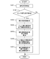
図5は、本実施例に係る増圧部4の制御フローを示したフローチャートである。本フローチャートは、ECU10により、燃焼サイクル毎に実施される。なお、アウタニードル6及びインナニードル7の制御は、別途ECU10により実行される。また、本フローチャートは、燃料噴射前から開始する。本実施例においては図5に示したフローチャートを実行するECU10が、本発明における制御装置に相当する。
FIG. 5 is a flowchart showing a control flow of the pressure booster 4 according to the present embodiment. This flowchart is executed by the
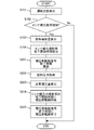
ステップS101では、内燃機関の運転状態が検出される。ここでは、機関負荷及び機関回転速度が検出される。本ステップは、燃料噴射量と相関関係にある物理量が検出される。 In step S101, the operating state of the internal combustion engine is detected. Here, the engine load and the engine speed are detected. In this step, a physical quantity that is correlated with the fuel injection quantity is detected.
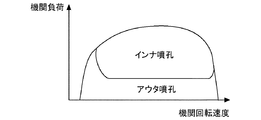
ステップS102では、内燃機関の運転領域が、インナ噴孔23を使用する領域であるか否か判定される。図6は、アウタ噴孔22及びインナ噴孔23を使用する運転領域を示した図である。横軸は機関回転速度であり、縦軸は機関負荷である。図6において「アウタ噴孔」で示される領域が、アウタ噴孔22のみを使用する領域であり、「インナ噴孔」で示される領域が、アウタ噴孔22及びインナ噴孔23を使用する領域である。図6の関係は予め実験またはシミュレーション等により求めてECU10に記憶させておく。インナ噴孔23は、燃料噴射量が比較的多い運転領域で使用される。ECU10は、ステップ
S101で検出される運転状態に基づいて、図6に示した関係から、内燃機関の運転領域が、アウタ噴孔22を使用する領域であるか否か判定する。ステップS102で肯定判定がなされた場合にはステップS103へ進み、一方、否定判定がなされた場合には本フローチャートを終了させる。
In step S102, it is determined whether or not the operating region of the internal combustion engine is a region in which the
ステップS103では、燃料噴射量が算出される。燃料噴射量は、ステップS101で検出される内燃機関の運転状態に基づいて算出される。この燃料噴射量は、1気筒で1サイクルに噴射する燃料の総量である。内燃機関の運転状態と燃料噴射量との関係は予め実験またはシミュレーション等により求めてマップ化しておいてもよい。 In step S103, the fuel injection amount is calculated. The fuel injection amount is calculated based on the operating state of the internal combustion engine detected in step S101. This fuel injection amount is the total amount of fuel injected in one cycle per cylinder. The relationship between the operating state of the internal combustion engine and the fuel injection amount may be obtained in advance by experiments or simulations and mapped.
ステップS104では、ステップS103で算出される燃料噴射量に基づいて、仮に増圧部4により燃料の増圧を実施しない場合に噴射率が低下を開始する時期が算出される。本ステップでは、増圧部4への駆動信号の入力を開始する時期を求めている。すなわち、本ステップでは、上記T8を求めている。燃料噴射量と、上記T8と、には相関関係があるため、この関係を予め求めておきECU10に記憶させておく。ここで、燃料噴射量と噴射信号を入力する期間とには相関関係がある。そして、噴射信号を入力する期間が決まれば、噴射信号の入力開始からのアウタニードル6及びインナニードル7のリフト量の推移も決まる。したがって、燃料噴射量と、噴射信号の入力開始から上記T8までの期間と、にも相関関係がある。このため、インナニードル7のリフト量が第二所定量となる時期を燃料噴射量に応じて求めることができる。なお、燃料噴射量は内燃機関の運転状態に基づいて設定されるため、内燃機関の運転状態に基づいて、仮に増圧部4により燃料の増圧を実施しない場合に噴射率が低下を開始する時期を算出することもできる。また、燃料噴射量と、噴射信号の入力開始時期及び噴射信号の入力期間は、増圧部4による増圧を前提として、内燃機関の運転状態と関連付けて予め実験またはシミュレーション等により求めてECU10に記憶させておく。また、仮に増圧部4により燃料の増圧を実施しない場合に噴射率が低下を開始する時期を、内燃機関の運転状態と関連付けて予め実験またはシミュレーション等により求めてマップ化し、ECU10に記憶させておいてもよい。
In step S104, based on the fuel injection amount calculated in step S103, the timing at which the injection rate starts to decrease when the pressure increase unit 4 does not perform fuel pressure increase is calculated. In this step, the timing for starting the input of the drive signal to the pressure booster 4 is obtained. That is, in this step, T8 is obtained. Since there is a correlation between the fuel injection amount and the T8, this relationship is obtained in advance and stored in the
ステップS105では、増圧部4への駆動信号の入力が終了する時期が算出される。例えば、増加圧力が0となるときに、アウタニードル6と弁座26との間の燃料の通路の断面積が、アウタ噴孔22の断面積と等しくなるように、増圧部4への駆動信号の入力が終了する時期を決定してもよい。この時期に代えて、アウタニードル6が弁座26に着座する時点を、増圧部4への駆動信号の入力が終了する時期としてもよいし、アウタニードル6が弁座26に着座する時点において増加圧力が0となるように増圧部4への駆動信号の入力が終了する時期を決定してもよい。さらに、増圧部4への駆動信号の入力が終了する最適な時期を、内燃機関の運転状態と関連付けて予め実験またはシミュレーション等により求めておいてもよい。燃料噴射量と、増圧部4への駆動信号の入力が終了する時期と、の関係をマップ化してECU10に記憶させておいてもよい。
In step S105, the time when the input of the drive signal to the pressure booster 4 is completed is calculated. For example, when the increased pressure becomes zero, the drive to the pressure increasing portion 4 is performed so that the cross-sectional area of the fuel passage between the
ステップS106では、ステップS104で算出された時期まで待ってから増圧部4へ駆動信号を入力する。すなわち、仮に増圧部4により燃料の増圧を実施しない場合に噴射率が低下を開始する時期(T8)に増圧部4の駆動を開始する。この時期(T8)は、噴射信号の入力開始時点からの経過時間を例えばタイマによってカウントすることで知ることができる。 In step S106, after waiting until the time calculated in step S104, a drive signal is input to the pressure increasing unit 4. That is, if the fuel pressure is not boosted by the pressure boosting unit 4, the driving of the pressure boosting unit 4 is started at a time (T8) when the injection rate starts to decrease. This time (T8) can be known by, for example, counting the elapsed time from the injection signal input start time by a timer.
ステップS107では、ステップS105で算出された時期まで待ってから増圧部4への駆動信号の入力を終了する。増圧部4への駆動信号の入力が終了する時期は、噴射信号の入力開始時点からの経過時間を例えばタイマによってカウントすることで知ることができる。 In step S107, the input of the drive signal to the pressure increasing unit 4 is terminated after waiting for the time calculated in step S105. The time when the input of the drive signal to the pressure increasing section 4 is completed can be known by counting the elapsed time from the injection signal input start time, for example, with a timer.
なお、図5に示すフローチャートでは、増圧部4への駆動信号の入力開始時期及び入力終了時期をサイクル毎に算出しているが、これに代えて、複数サイクル毎に算出してもよい。また、過去の複数サイクルの燃料噴射量の平均値を用いて増圧部4への駆動信号の入力開始時期及び入力終了時期を算出してもよい。 In the flowchart shown in FIG. 5, the input start time and the input end time of the drive signal to the pressure booster 4 are calculated for each cycle, but instead may be calculated for a plurality of cycles. Further, the input start timing and input end timing of the drive signal to the pressure increasing section 4 may be calculated using the average value of the fuel injection amounts in the past plural cycles.
また、図5に示すフローチャートでは、ステップS104において、仮に増圧部4により燃料の増圧を実施しない場合に噴射率が低下を開始する時期を算出しているが、これに代えて、インナニードル7のリフト量を検出するセンサを設け、センサにより検出されるリフト量が第二所定量に達したときに増圧部4による燃料の増圧を開始してもよい。また、圧力センサ19の検出値に基づいて、インナニードル7のリフト量が第二所定量に達したことを知ることもできるため、圧力センサ19の検出値に基づいて、増圧部4による燃料の増圧を開始してもよい。
In the flowchart shown in FIG. 5, in step S104, when the fuel pressure is not increased by the pressure increasing unit 4, the timing at which the injection rate starts decreasing is calculated. Instead, the
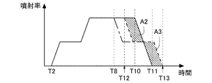
このようにして、インナ噴孔23の噴射率の低下開始時期に合わせて燃料圧力を増加させることにより、燃料の噴射率が低下することを抑制できる。ここで、図7は、従来の燃料噴射時の噴射率と、本実施例に係る燃料噴射時の噴射率と、を比較するためのタイムチャートである。実線は本実施例に係る噴射率を示し、破線は従来の噴射率を示している。また、一点鎖線は、本実施例と同じ期間に背圧部3を駆動させた場合で、且つ、増圧部4による燃料の圧力の増加を実施しない場合を示している。T2,T8,T10,T11の時点は、図4と同じである。ハッチング部分のA2の面積と、ハッチング部分のA3の面積と、は等しい。したがって、図7は、本実施例に係る燃料噴射量と従来に係る燃料噴射量とが等しい場合を示している。
In this way, it is possible to suppress the fuel injection rate from decreasing by increasing the fuel pressure in accordance with the start timing of the decrease in the injection rate of the
従来では、T12で示す時点においてインナ噴孔23からの燃料の噴射率の低下が始まる。従来では、燃料の増圧は行っていないため、T12からインナ噴孔23の噴射率が低下すると、燃料噴射弁1の全体としての噴射率も低下する。そして、T13で示す時点において、アウタ噴孔22が閉塞されて噴射率が0になる。一方、本実施例では、従来よりも噴射信号の入力期間を短くしているため、アウタニードル6及びインナニードル7が従来よりも早く下降を始める。このため、T8で示す時点においてインナ噴孔23からの燃料の噴射率が低下し得る。しかし、本実施例では、T8から燃料の圧力を増加させているため、噴射率の低下は抑制される。そして、従来よりも早い時期にアウタニードル6及びインナニードル7が下降を始めるため、従来において噴射率が0となる時点T13よりも前に、本実施例に係る噴射率が0となる時点T11が到来する。このため、本実施例では従来と同じ量の燃料を噴射させる場合であっても、噴射期間を短くすることができる。そして、本実施例のように噴射期間を短縮すれば、燃料と空気との混合が不十分のまま燃焼が行われることを抑制できるため、スモークを低減することができる。また、燃料の圧力を増加させることにより燃料の微粒化が可能となるため、これによってもスモークを低減することができる。さらに、燃料状態の改善により、燃費を向上させることもできる。
Conventionally, the fuel injection rate from the
ところで、燃料噴射開始時から燃料の圧力を増加することによっても、燃料噴射期間を短縮することができる。しかし、燃料噴射開始時に燃料の噴射率が高いと、急激な燃焼が起こり得るために騒音が発生する虞がある。また、燃焼温度が高くなりすぎてNOxの排出量が増加する虞もある。これに対し、本実施例のように、燃料噴射開始時には比較的低い圧力で燃料を噴射することにより、騒音の発生を抑制することができ、また、NOxの発生も抑制することができる。 Incidentally, the fuel injection period can also be shortened by increasing the fuel pressure from the start of fuel injection. However, if the fuel injection rate is high at the start of fuel injection, rapid combustion may occur and noise may occur. Further, the combustion temperature may become too high, and the NOx emission amount may increase. On the other hand, as in this embodiment, by injecting fuel at a relatively low pressure at the start of fuel injection, it is possible to suppress the generation of noise and also suppress the generation of NOx.
<実施例2>
本実施例では、増圧部4により燃料の圧力を増加させるときに、噴射率が一定となるように増圧部4を制御する。そのため、本実施例に係る増圧部4は、燃料の圧力を任意に調整することができるものとする。その他の装置等は実施例1と同じため説明を省略する。
<Example 2>
In the present embodiment, when the pressure of the fuel is increased by the pressure increasing portion 4, the pressure increasing portion 4 is controlled so that the injection rate becomes constant. For this reason, the pressure increasing unit 4 according to the present embodiment can arbitrarily adjust the fuel pressure. Since other devices are the same as those in the first embodiment, the description thereof is omitted.
実施例1に係る増圧部4は、所定の比率で燃料の圧力を増加させるものであり、燃料の圧力に応じた制御を行ってはいない。燃料の圧力は内燃機関の運転状態によって変化し得るため、所定の比率で燃料の圧力を増加させる場合には、増圧部4により燃料の増圧を行う前後で噴射率が変化する虞がある。噴射率が変化すると、トルク変動が起こる虞がある。本実施例では、噴射率が一定となるような燃料の増圧量を算出し、この算出した燃料の増圧量が得られるように、増圧部4を駆動する。 The pressure increasing unit 4 according to the first embodiment increases the fuel pressure at a predetermined ratio, and does not perform control according to the fuel pressure. Since the fuel pressure can change depending on the operating state of the internal combustion engine, when the fuel pressure is increased at a predetermined ratio, there is a possibility that the injection rate changes before and after the pressure is increased by the pressure increasing section 4. . When the injection rate changes, torque fluctuation may occur. In the present embodiment, the pressure increase amount of the fuel is calculated so that the injection rate is constant, and the pressure increase portion 4 is driven so that the calculated fuel pressure increase amount is obtained.
図8は、本実施例に係る増圧部4の制御フローを示したフローチャートである。本フローチャートは、ECU10により、燃焼サイクル毎に実施される。なお、アウタニードル6及びインナニードル7の制御は、別途ECU10により実行される。上記のフローチャートと同じ処理がなされるステップについては、同じ符号を付して説明を省略する。本実施例においては図8に示したフローチャートを実行するECU10が、本発明における制御装置に相当する。
FIG. 8 is a flowchart showing a control flow of the pressure booster 4 according to the present embodiment. This flowchart is executed by the
図8に示すフローチャートでは、ステップS104の処理が終了するとステップS201へ進む。ステップS201では、増圧部4への駆動信号の入力が終了する時期が算出される。例えば、増加圧力が0となるときに、アウタニードル6と弁座26との間の燃料の通路の断面積が、アウタ噴孔22の断面積と等しくなるように、増圧部4への駆動信号の入力が終了する時期を決定してもよい。この時期に代えて、アウタニードル6が弁座26に着座する時点を、増圧部4への駆動信号の入力が終了する時期としてもよいし、アウタニードル6が弁座26に着座する時点において増加圧力が0となるように増圧部4への駆動信号の入力が終了する時期を決定してもよい。さらに、増圧部4への駆動信号の入力が終了する最適な時期を、内燃機関の運転状態と関連付けて予め実験またはシミュレーション等により求めておいてもよい。燃料噴射量と、増圧部4への駆動信号の入力が終了する時期と、の関係をマップ化してECU10に記憶させておいてもよい。
In the flowchart shown in FIG. 8, when the process of step S104 ends, the process proceeds to step S201. In step S201, the time when the input of the drive signal to the pressure boosting unit 4 ends is calculated. For example, when the increased pressure becomes zero, the drive to the pressure increasing portion 4 is performed so that the cross-sectional area of the fuel passage between the
ステップS202では、燃料の圧力が取得される。この燃料の圧力は、仮に増圧部4による燃料の増加を実施しない場合の燃料の圧力であって、図4におけるT9からT10の期間における燃料の圧力である。本ステップでは、増圧部4により増圧する前の燃料の圧力を求めている。この燃料の圧力は内燃機関の運転状態と相関関係にあることから、内燃機関の運転状態に基づいて燃料の圧力を取得することができる。なお、内燃機関の運転状態と燃料の圧力との関係は、予め実験等により求めてECU10に記憶させておく。
In step S202, the fuel pressure is acquired. This fuel pressure is the fuel pressure when the fuel is not increased by the pressure increasing section 4, and is the fuel pressure during the period from T9 to T10 in FIG. In this step, the pressure of the fuel before being increased by the pressure increasing unit 4 is obtained. Since the fuel pressure is correlated with the operating state of the internal combustion engine, the fuel pressure can be acquired based on the operating state of the internal combustion engine. Note that the relationship between the operating state of the internal combustion engine and the fuel pressure is obtained in advance through experiments or the like and stored in the
ステップS203では、必要増圧量が算出される。必要増圧量は、増圧部4により燃料の圧力を増加させるときの燃料の圧力の増加量である。本ステップでは、アウタ噴孔22のみから燃料が噴射されているときの燃料の噴射率(図4におけるT9からT10の期間の噴射率)が、アウタ噴孔22及びインナ噴孔23の両方から燃料が噴射されているときの燃料の噴射率(図4におけるT8の噴射率)と等しくなるように、必要増圧量が算出される。ここで、必要増圧量は、以下の関係に基づいて算出される。

DQは、図4におけるT8の時点での燃料の噴射率であり内燃機関の運転状態と相関関係にあることから、該内燃機関の運転状態に基づいて求められる。内燃機関の運転状態と、DQとの関係は予め実験またはシミュレーション等により求めることができる。CDは、流量係数であり予め求めておく。Aは、アウタ噴孔22の断面積であり予め求めておく
。PCRは、増圧後の燃料圧力であって、噴射率を一定に保つために必要とされる燃料圧力である。PAは、燃料噴射時の雰囲気圧力(燃焼室内圧力)であり、内燃機関の運転状態に基づいて推定することができるが、燃料圧力PCRと比較して十分に小さいため、本実施例では0とする。Dは、燃料の密度であり、想定される燃料の密度を予め求めておく。この式に基づいて燃料圧力PCRを算出することができる。この燃料圧力PCRから、ステップS202で取得される燃料圧力を減算することで、必要増圧量が算出される。
In step S203, a necessary pressure increase amount is calculated. The necessary pressure increase amount is an increase amount of the fuel pressure when the pressure of the fuel is increased by the pressure increasing portion 4. In this step, the fuel injection rate (injection rate during the period from T9 to T10 in FIG. 4) when the fuel is injected only from the
DQ is the fuel injection rate at time T8 in FIG. 4 and has a correlation with the operating state of the internal combustion engine, and is obtained based on the operating state of the internal combustion engine. The relationship between the operating state of the internal combustion engine and DQ can be obtained in advance by experiments or simulations. CD is a flow coefficient and is obtained in advance. A is a cross-sectional area of the
ステップS204では、ステップS104で算出された時期まで待ってから増圧部4へ駆動信号を入力する。すなわち、インナ噴孔23からの燃料の噴射率が低下を開始する時期(T8)に増圧部4の駆動を開始する。インナ噴孔23からの燃料の噴射率が低下を開始する時期(T8)は、噴射信号の入力開始時点からの経過時間を例えばタイマによってカウントすることで知ることができる。このときには、必要増圧量分だけ燃料の圧力が高くなるように、増圧部4が制御される。
In step S204, after waiting until the time calculated in step S104, a drive signal is input to the pressure increasing unit 4. That is, the driving of the pressure increasing section 4 is started at a time (T8) when the fuel injection rate from the
ステップS205では、ステップS201で算出された時期まで待ってから増圧部4への駆動信号の入力を終了する。増圧部4への駆動信号の入力が終了する時期は、噴射信号の入力開始時点からの経過時間を例えばタイマによってカウントすることで知ることができる。 In step S205, after waiting until the time calculated in step S201, the input of the drive signal to the pressure increasing unit 4 is finished. The time when the input of the drive signal to the pressure increasing section 4 is completed can be known by counting the elapsed time from the injection signal input start time, for example, with a timer.
なお、図8に示したフローチャートでは、ステップS203で算出される必要増圧量の分だけ燃料の圧力を増加させているため、圧力センサ19による検出値を用いた制御は行っていない。すなわち、アウタ噴孔22のみから燃料が噴射されているときに、予め求めておいた必要増圧量分だけ燃料の圧力を増加している。これに代えて、本実施例では、ステップS205まで燃料の噴射率が一定となるように燃料の圧力をフィードバック制御してもよい。すなわち、圧力センサ19により検出される圧力が、ステップS203で算出される燃料圧力PCRとなるように、増圧部4を制御してもよい。
In the flowchart shown in FIG. 8, since the fuel pressure is increased by the necessary pressure increase amount calculated in step S203, the control using the detection value by the
以上説明したように本実施例によれば、インナニードル7の下降時において噴射率が変化することを抑制できるため、トルク変動が起こることを抑制できる。
As described above, according to the present embodiment, since the change in the injection rate can be suppressed when the
1 燃料噴射弁
2 ノズル部
3 背圧部
4 増圧部
6 アウタニードル
7 インナニードル
10 ECU
17 アクセル開度センサ
18 クランクポジションセンサ
19 圧力センサ
21 ノズルボディ
22 アウタ噴孔
23 インナ噴孔
26 弁座
31 背圧室
32 ノズル室
63 溝
73 突起
DESCRIPTION OF
17
総噴孔面積が大きい状態から小さい状態へ変わることにより噴射率が低下し得るが、このときに噴射される燃料の圧力を増加させることにより、実際に噴射率が低下することを抑制できる。すなわち、噴射率が高い状態を維持することができる。その結果、燃料噴射
量の総量を変化させずに、ニードルを下降させる時期を早くすることができるので、燃料の噴射期間を短縮することができる。このため、スモークが発生することを抑制できる。また、燃料の圧力の増加により、燃料の微粒化を促進させることもできるので、燃焼を促進させることができ、これによっても、スモークの発生を抑制できる。
Although the injection rate can be reduced by changing the total nozzle hole area from a large state to a small state, it is possible to suppress the actual reduction in the injection rate by increasing the pressure of the fuel injected at this time. That is, it is possible to maintain a high injection rate. As a result, the timing for lowering the needle can be advanced without changing the total amount of fuel injection, so the fuel injection period can be shortened. For this reason, it is possible to suppress the occurrence of smoke. Further, since the atomization of the fuel can be promoted by increasing the pressure of the fuel, the combustion can be promoted, and the generation of smoke can be suppressed also by this .
また、前記燃料噴射弁が、第一噴孔と、第二噴孔と、該第一噴孔を開閉する第一ニードルと、該第二噴孔を開閉し該第一ニードルのリフト量が第一所定量以上のときに該第一ニードルと共にリフトする第二ニードルと、を有する燃料噴射装置において、前記燃料噴射弁から噴射される燃料の圧力を変化させる圧力変化部をさらに備え、前記制御装置は、前記第一ニードルのリフト量が前記第一所定量以上になった後、前記第一ニードル及び前記第二ニードルが下降して、前記第二ニードルのリフト量が、第二所定量になるときに、前記圧力変化部による燃料の圧力の増加を開始する。
The fuel injection valve includes a first injection hole, a second injection hole, a first needle that opens and closes the first injection hole, and opens and closes the second injection hole. And a second needle that lifts together with the first needle when the amount exceeds a predetermined amount, further comprising a pressure changing unit that changes a pressure of the fuel injected from the fuel injection valve, After the lift amount of the first needle becomes equal to or greater than the first predetermined amount, the first needle and the second needle are lowered, and the lift amount of the second needle becomes the second predetermined amount. Sometimes, the pressure change unit starts increasing the fuel pressure .
Claims (4)
前記総噴孔面積が大きい状態から小さい状態へ変わるときに、前記総噴孔面積が大きい状態のときよりも小さい状態のときの方が燃料の圧力が大きくなるように燃料の圧力を増加する制御装置と、
を備える燃料噴射装置。 A fuel injection valve in which the total nozzle hole area becomes larger when the operation amount of the needle is large than when it is small;
Control for increasing the fuel pressure so that when the total nozzle hole area changes from a large state to a small state, the fuel pressure increases when the total nozzle hole area is smaller than when the total nozzle hole area is large. Equipment,
A fuel injection device comprising:
前記燃料噴射弁から噴射される燃料の圧力を変化させる圧力変化部をさらに備え、
前記制御装置は、前記第一ニードルのリフト量が前記第一所定量以上になった後、前記第一ニードル及び前記第二ニードルが下降して、前記第二ニードルのリフト量が、第二所定量になるときに、前記圧力変化部による燃料の圧力の増加を開始する請求項1に記載の燃料噴射装置。 The fuel injection valve includes a first injection hole, a second injection hole, a first needle that opens and closes the first injection hole, and a lift amount of the first needle that opens and closes the second injection hole. A fuel injection device having a second needle that lifts together with the first needle when the amount exceeds a predetermined value;
A pressure change unit that changes the pressure of the fuel injected from the fuel injection valve;
After the lift amount of the first needle becomes equal to or greater than the first predetermined amount, the control device lowers the first needle and the second needle so that the lift amount of the second needle The fuel injection device according to claim 1, wherein the fuel pressure is started to be increased by the pressure changing unit when the amount becomes constant.
Priority Applications (3)
| Application Number | Priority Date | Filing Date | Title |
|---|---|---|---|
| JP2015029805A JP5962795B1 (en) | 2015-02-18 | 2015-02-18 | Fuel injection device |
| US15/045,541 US20160237972A1 (en) | 2015-02-18 | 2016-02-17 | Fuel injection apparatus |
| DE102016102773.1A DE102016102773A1 (en) | 2015-02-18 | 2016-02-17 | Fuel injection system |
Applications Claiming Priority (1)
| Application Number | Priority Date | Filing Date | Title |
|---|---|---|---|
| JP2015029805A JP5962795B1 (en) | 2015-02-18 | 2015-02-18 | Fuel injection device |
Publications (2)
| Publication Number | Publication Date |
|---|---|
| JP5962795B1 JP5962795B1 (en) | 2016-08-03 |
| JP2016151237A true JP2016151237A (en) | 2016-08-22 |
Family
ID=56552000
Family Applications (1)
| Application Number | Title | Priority Date | Filing Date |
|---|---|---|---|
| JP2015029805A Expired - Fee Related JP5962795B1 (en) | 2015-02-18 | 2015-02-18 | Fuel injection device |
Country Status (3)
| Country | Link |
|---|---|
| US (1) | US20160237972A1 (en) |
| JP (1) | JP5962795B1 (en) |
| DE (1) | DE102016102773A1 (en) |
Families Citing this family (3)
| Publication number | Priority date | Publication date | Assignee | Title |
|---|---|---|---|---|
| EP2674608B1 (en) * | 2012-06-13 | 2015-08-12 | Delphi International Operations Luxembourg S.à r.l. | Fuel injector |
| US11105307B2 (en) * | 2017-02-03 | 2021-08-31 | Transportation Ip Holdings, Llc | Method and systems for a multi-needle fuel injector |
| JP7047751B2 (en) | 2018-12-25 | 2022-04-05 | マツダ株式会社 | Compression ignition engine |
Citations (15)
| Publication number | Priority date | Publication date | Assignee | Title |
|---|---|---|---|---|
| JPS63136259U (en) * | 1987-02-27 | 1988-09-07 | ||
| JPH03246364A (en) * | 1990-02-26 | 1991-11-01 | Zexel Corp | Injection nozzle and its injection pressure control device |
| JP2000073905A (en) * | 1997-08-28 | 2000-03-07 | Denso Corp | Fuel injection system for internal combustion engine |
| US6601566B2 (en) * | 2001-07-11 | 2003-08-05 | Caterpillar Inc | Fuel injector with directly controlled dual concentric check and engine using same |
| US6769635B2 (en) * | 2002-09-25 | 2004-08-03 | Caterpillar Inc | Mixed mode fuel injector with individually moveable needle valve members |
| JP2006183468A (en) * | 2004-12-24 | 2006-07-13 | Denso Corp | Fuel injection device |
| JP2006220129A (en) * | 2005-02-14 | 2006-08-24 | Denso Corp | Fuel injection nozzle, fuel injection valve, and fuel injection device |
| JP2007016773A (en) * | 2005-06-06 | 2007-01-25 | Denso Corp | Fuel injection valve and its manufacturing method |
| JP2008261224A (en) * | 2007-04-10 | 2008-10-30 | Toyota Motor Corp | Fuel injection control device of internal combustion engine |
| JP2008280958A (en) * | 2007-05-11 | 2008-11-20 | Denso Corp | Fuel injection valve |
| JP2009150312A (en) * | 2007-12-20 | 2009-07-09 | Toyota Motor Corp | Injector |
| JP2009529617A (en) * | 2006-03-10 | 2009-08-20 | ボルボ ラストバグナー アーベー | Fuel injection device |
| US20090283612A1 (en) * | 2008-05-19 | 2009-11-19 | Caterpillar Inc. | Seal arrangement for a fuel injector needle valve |
| JP2009542953A (en) * | 2006-07-04 | 2009-12-03 | ルノー・トラックス | Nozzle assembly, fuel injector and internal combustion engine comprising such an injector |
| JP2011144728A (en) * | 2010-01-13 | 2011-07-28 | Toyota Motor Corp | Fuel injection valve and direct injection type internal combustion engine |
Family Cites Families (5)
| Publication number | Priority date | Publication date | Assignee | Title |
|---|---|---|---|---|
| DE69922087T2 (en) * | 1998-06-24 | 2005-12-01 | Delphi Technologies, Inc., Troy | fuel injector |
| GB9914642D0 (en) * | 1999-06-24 | 1999-08-25 | Lucas Ind Plc | Fuel injector |
| US7243862B2 (en) * | 2004-04-07 | 2007-07-17 | Delphi Technologies, Inc. | Apparatus and method for mode-switching fuel injector nozzle |
| JP2006161678A (en) | 2004-12-07 | 2006-06-22 | Denso Corp | Fuel injection nozzle, fuel injection valve and fuel injection device |
| US9562505B2 (en) * | 2013-06-11 | 2017-02-07 | Cummins Inc. | System and method for control of fuel injector spray |
-
2015
- 2015-02-18 JP JP2015029805A patent/JP5962795B1/en not_active Expired - Fee Related
-
2016
- 2016-02-17 DE DE102016102773.1A patent/DE102016102773A1/en not_active Withdrawn
- 2016-02-17 US US15/045,541 patent/US20160237972A1/en not_active Abandoned
Patent Citations (15)
| Publication number | Priority date | Publication date | Assignee | Title |
|---|---|---|---|---|
| JPS63136259U (en) * | 1987-02-27 | 1988-09-07 | ||
| JPH03246364A (en) * | 1990-02-26 | 1991-11-01 | Zexel Corp | Injection nozzle and its injection pressure control device |
| JP2000073905A (en) * | 1997-08-28 | 2000-03-07 | Denso Corp | Fuel injection system for internal combustion engine |
| US6601566B2 (en) * | 2001-07-11 | 2003-08-05 | Caterpillar Inc | Fuel injector with directly controlled dual concentric check and engine using same |
| US6769635B2 (en) * | 2002-09-25 | 2004-08-03 | Caterpillar Inc | Mixed mode fuel injector with individually moveable needle valve members |
| JP2006183468A (en) * | 2004-12-24 | 2006-07-13 | Denso Corp | Fuel injection device |
| JP2006220129A (en) * | 2005-02-14 | 2006-08-24 | Denso Corp | Fuel injection nozzle, fuel injection valve, and fuel injection device |
| JP2007016773A (en) * | 2005-06-06 | 2007-01-25 | Denso Corp | Fuel injection valve and its manufacturing method |
| JP2009529617A (en) * | 2006-03-10 | 2009-08-20 | ボルボ ラストバグナー アーベー | Fuel injection device |
| JP2009542953A (en) * | 2006-07-04 | 2009-12-03 | ルノー・トラックス | Nozzle assembly, fuel injector and internal combustion engine comprising such an injector |
| JP2008261224A (en) * | 2007-04-10 | 2008-10-30 | Toyota Motor Corp | Fuel injection control device of internal combustion engine |
| JP2008280958A (en) * | 2007-05-11 | 2008-11-20 | Denso Corp | Fuel injection valve |
| JP2009150312A (en) * | 2007-12-20 | 2009-07-09 | Toyota Motor Corp | Injector |
| US20090283612A1 (en) * | 2008-05-19 | 2009-11-19 | Caterpillar Inc. | Seal arrangement for a fuel injector needle valve |
| JP2011144728A (en) * | 2010-01-13 | 2011-07-28 | Toyota Motor Corp | Fuel injection valve and direct injection type internal combustion engine |
Also Published As
| Publication number | Publication date |
|---|---|
| JP5962795B1 (en) | 2016-08-03 |
| US20160237972A1 (en) | 2016-08-18 |
| DE102016102773A1 (en) | 2016-08-18 |
Similar Documents
| Publication | Publication Date | Title |
|---|---|---|
| JP6462835B2 (en) | Drive device for fuel injection device | |
| JP6400825B2 (en) | Drive device for fuel injection device | |
| JP5796567B2 (en) | Fuel injection valve | |
| JP4587133B2 (en) | Fuel supply device | |
| JP4535032B2 (en) | Fuel injection control device | |
| JP6098613B2 (en) | Internal combustion engine | |
| JP5962795B1 (en) | Fuel injection device | |
| US10634085B2 (en) | Control device for fuel pump and control method thereof | |
| JP6457908B2 (en) | Control device and fuel injection system | |
| JP6156397B2 (en) | Internal combustion engine | |
| JP6203159B2 (en) | Fuel injection device | |
| JP2005315195A (en) | Fuel injection control method of boosting common rail type fuel injector | |
| JP2010090804A (en) | Fuel injection device | |
| WO2019021732A1 (en) | Fuel injection control device and fuel injection control method | |
| JP2011094635A (en) | Fuel injection control system for internal combustion engine | |
| JP5529681B2 (en) | Constant residual pressure valve | |
| JP6432563B2 (en) | Control device for internal combustion engine | |
| JP2019039323A (en) | Fuel injection control device | |
| JP2016211468A (en) | Internal combustion engine | |
| JP6358271B2 (en) | Fuel injection device for internal combustion engine | |
| JP7459834B2 (en) | Fuel injection control device for internal combustion engine | |
| JP4735621B2 (en) | Injection amount learning device | |
| JP2010248930A (en) | Fuel injection device | |
| US20210388790A1 (en) | Control Device for Vehicle Fuel Injection Control Method for Vehicle and Fuel Injection Control Program for Vehicle | |
| JP2010236494A (en) | Fuel injection valve and fuel injection device |
Legal Events
| Date | Code | Title | Description |
|---|---|---|---|
| TRDD | Decision of grant or rejection written | ||
| A01 | Written decision to grant a patent or to grant a registration (utility model) |
Free format text: JAPANESE INTERMEDIATE CODE: A01 Effective date: 20160531 |
|
| A61 | First payment of annual fees (during grant procedure) |
Free format text: JAPANESE INTERMEDIATE CODE: A61 Effective date: 20160613 |
|
| R151 | Written notification of patent or utility model registration |
Ref document number: 5962795 Country of ref document: JP Free format text: JAPANESE INTERMEDIATE CODE: R151 |
|
| LAPS | Cancellation because of no payment of annual fees |