JP2016150741A - Movable body aerodynamic control device - Google Patents
Movable body aerodynamic control device Download PDFInfo
- Publication number
- JP2016150741A JP2016150741A JP2015031168A JP2015031168A JP2016150741A JP 2016150741 A JP2016150741 A JP 2016150741A JP 2015031168 A JP2015031168 A JP 2015031168A JP 2015031168 A JP2015031168 A JP 2015031168A JP 2016150741 A JP2016150741 A JP 2016150741A
- Authority
- JP
- Japan
- Prior art keywords
- shielding member
- air flow
- shielding
- vehicle
- moving body
- Prior art date
- Legal status (The legal status is an assumption and is not a legal conclusion. Google has not performed a legal analysis and makes no representation as to the accuracy of the status listed.)
- Pending
Links
Images


Classifications
-
- B—PERFORMING OPERATIONS; TRANSPORTING
- B62—LAND VEHICLES FOR TRAVELLING OTHERWISE THAN ON RAILS
- B62D—MOTOR VEHICLES; TRAILERS
- B62D35/00—Vehicle bodies characterised by streamlining
- B62D35/008—Side spoilers
-
- B—PERFORMING OPERATIONS; TRANSPORTING
- B62—LAND VEHICLES FOR TRAVELLING OTHERWISE THAN ON RAILS
- B62D—MOTOR VEHICLES; TRAILERS
- B62D35/00—Vehicle bodies characterised by streamlining
- B62D35/02—Streamlining the undersurfaces
-
- B—PERFORMING OPERATIONS; TRANSPORTING
- B62—LAND VEHICLES FOR TRAVELLING OTHERWISE THAN ON RAILS
- B62D—MOTOR VEHICLES; TRAILERS
- B62D37/00—Stabilising vehicle bodies without controlling suspension arrangements
- B62D37/02—Stabilising vehicle bodies without controlling suspension arrangements by aerodynamic means
-
- Y—GENERAL TAGGING OF NEW TECHNOLOGICAL DEVELOPMENTS; GENERAL TAGGING OF CROSS-SECTIONAL TECHNOLOGIES SPANNING OVER SEVERAL SECTIONS OF THE IPC; TECHNICAL SUBJECTS COVERED BY FORMER USPC CROSS-REFERENCE ART COLLECTIONS [XRACs] AND DIGESTS
- Y02—TECHNOLOGIES OR APPLICATIONS FOR MITIGATION OR ADAPTATION AGAINST CLIMATE CHANGE
- Y02T—CLIMATE CHANGE MITIGATION TECHNOLOGIES RELATED TO TRANSPORTATION
- Y02T10/00—Road transport of goods or passengers
- Y02T10/80—Technologies aiming to reduce greenhouse gasses emissions common to all road transportation technologies
- Y02T10/82—Elements for improving aerodynamics
-
- Y—GENERAL TAGGING OF NEW TECHNOLOGICAL DEVELOPMENTS; GENERAL TAGGING OF CROSS-SECTIONAL TECHNOLOGIES SPANNING OVER SEVERAL SECTIONS OF THE IPC; TECHNICAL SUBJECTS COVERED BY FORMER USPC CROSS-REFERENCE ART COLLECTIONS [XRACs] AND DIGESTS
- Y02—TECHNOLOGIES OR APPLICATIONS FOR MITIGATION OR ADAPTATION AGAINST CLIMATE CHANGE
- Y02T—CLIMATE CHANGE MITIGATION TECHNOLOGIES RELATED TO TRANSPORTATION
- Y02T10/00—Road transport of goods or passengers
- Y02T10/80—Technologies aiming to reduce greenhouse gasses emissions common to all road transportation technologies
- Y02T10/88—Optimized components or subsystems, e.g. lighting, actively controlled glasses
Landscapes
- Engineering & Computer Science (AREA)
- Chemical & Material Sciences (AREA)
- Combustion & Propulsion (AREA)
- Transportation (AREA)
- Mechanical Engineering (AREA)
- Physics & Mathematics (AREA)
- Fluid Mechanics (AREA)
- Body Structure For Vehicles (AREA)
Abstract
Description
本発明は、自動車等の車両又は航空機、ホバークラフト、リニアモータカー、船舶などのその他の移動体の空力制御装置に係り、より詳細には、車両又はその他の移動体の走行中に車両又はその他の移動体が受ける空気力を変更するための装置に係る。 The present invention relates to an aerodynamic control device for vehicles such as automobiles or other moving bodies such as airplanes, hovercrafts, linear motor cars, and ships, and more particularly, the vehicle or other movements while the vehicle or other moving bodies are traveling. It relates to a device for changing the aerodynamic force received by the body.
自動車等の車両又はその他の移動体の走行中、その車体又は胴体の周囲を流れる空気の流れから受ける力(空気力又は空力)は、車両又はその他の移動体の走行安定性、燃費等に大きく影響を及ぼすところ、かかる車体又は胴体に作用する空気力又は空力は、車両又はその他の移動体の走行状態(移動速度、旋回挙動など)や風又は空気流の状態(向き、大きさ)によって変化する。そこで、従前より、走行状態や空気流の状態に応じて、走行中の車両又はその他の移動体の車体又は胴体の空力特性を変化させて、車体又は胴体に作用する空気力又は空力を制御し、車体又は胴体の走行挙動又は運動の安定化を図る構成が種々提案されている。例えば、特許文献1に於いては、大型トラックの荷台後部の下方に、後端に向けて地上高が高くなる方向に幅が狭くなったサイドスカートが設けられ、そのサイドスカートに、車速が設定値以上になると、下方へ突出する側面整流補助部が装着され、これにより、車両の直進時の空気抵抗を低減する構成が提案されている。また、特許文献2に於いては、車両の前方から走行風を取り込み、その空気流を後方の下面の傾斜部へ排出して、車両後端に於ける剥離領域の渦流の発生を抑制し、空気抵抗の低減を図る構成が提案されている。更に、特許文献3に於いては、車両の前端に於けるバンパーカバーの左右の角部が、それぞれ、独立に、車速、舵角、ヨーレートなどに基づいて、突出変形可能となっており、これにより、車両の旋回状態に応じて、車両の前端の左右の角部に於ける空気抵抗を低減して、車両の走行安定性を図る構成が提案されている。 The force (aerodynamic force or aerodynamic force) received from the flow of air flowing around the vehicle body or the fuselage during traveling of a vehicle such as an automobile or other moving body greatly affects the running stability, fuel consumption, etc. of the vehicle or other moving body. As a result, the aerodynamic force or aerodynamic force acting on the vehicle body or fuselage varies depending on the traveling state (moving speed, turning behavior, etc.) of the vehicle or other moving body and the state of wind or airflow (direction, size). To do. Therefore, conventionally, the aerodynamic or aerodynamic force acting on the vehicle body or the fuselage is controlled by changing the aerodynamic characteristics of the vehicle body or the fuselage of the vehicle or other moving body that is traveling according to the traveling state or the airflow state. Various configurations for stabilizing the running behavior or motion of the vehicle body or the body have been proposed. For example, in Patent Document 1, a side skirt having a narrow width in the direction in which the ground height increases toward the rear end is provided below the rear part of a large truck, and the vehicle speed is set on the side skirt. When the value exceeds the value, a side rectification assisting portion that protrudes downward is attached, and thereby a configuration for reducing the air resistance when the vehicle goes straight has been proposed. Further, in Patent Document 2, the traveling wind is taken from the front of the vehicle, the air flow is discharged to the inclined portion of the rear lower surface, and the generation of the vortex in the separation region at the rear end of the vehicle is suppressed, A configuration for reducing air resistance has been proposed. Furthermore, in Patent Document 3, the left and right corners of the bumper cover at the front end of the vehicle can be protruded and deformed independently based on the vehicle speed, rudder angle, yaw rate, etc. Thus, a configuration has been proposed in which the air resistance at the left and right corners of the front end of the vehicle is reduced in accordance with the turning state of the vehicle to improve the running stability of the vehicle.
ところで、走行中の車両が横風を受けた場合に、その車両の挙動の安定化は、典型的には、タイヤの路面反力の制御により為される場合が多い。しかしながら、低抵抗化された車重の軽いコンパクト車両の場合、通常の自動車等の車両に比して、タイヤ路面反力の制御による挙動安定化の効果が低くなる。コンパクト車両に於いては、タイヤ幅が細く、接地荷重も小さいので、タイヤに発生する横力が比較的小さく、従って、横風外乱を受けたときには、その影響を抑制するのに十分なタイヤ横力を発生できない場合が起き得る。そこで、軽重量車両の場合のように、タイヤの路面反力の制御の効果が比較的低い場合、例えば、空中を移動する移動体なども含めて、その横風外乱に対する挙動安定化の対策の一つとして、車体又は胴体の空力特性を制御することが考えられる。 By the way, when a running vehicle receives a cross wind, the behavior of the vehicle is typically stabilized by controlling the road surface reaction force of the tire in many cases. However, in the case of a compact vehicle having a low resistance and a light weight, the effect of stabilizing the behavior by controlling the tire road surface reaction force is lower than that of a vehicle such as a normal automobile. In compact vehicles, the tire width is narrow and the ground contact load is small, so the lateral force generated on the tire is relatively small. Therefore, when the vehicle is subjected to a side wind disturbance, the tire side force is sufficient to suppress the effect. There may be cases where it is impossible to generate. Therefore, when the effect of the control of the road surface reaction force of the tire is relatively low as in the case of a light weight vehicle, for example, a measure for stabilizing the behavior against a cross wind disturbance including a moving body moving in the air. One possible method is to control the aerodynamic characteristics of the vehicle body or the fuselage.
車両又は胴体の空力特性に関して、端的に述べれば、まず、空気抵抗は、概ね、車両又はその他の移動体の進行方向に対し逆向きに働く圧力場の面積分に対応するので、一般的には、車両又はその他の移動体の直進時の流体中の抵抗の低減の一つの方法に於いては、車体又は胴体の形状に於いて、コーナー部が曲率半径の大きな曲面形状に形成される。しかしながら、そのような形状の移動体に於いて、その進行方向に対してヨー角が発生した状態で、横風が作用した場合、後述の実施形態の欄に於いて詳細に説明される如く、移動体を風下側に回頭させる方向に大きなヨーモーメントや横方向への横力が発生することとなり(例えば、コーナー部が曲率半径の大きな曲面形状に形成された低抵抗で知られている翼型の形状を、居住スペースを中央部に設けた車両又はその他の移動体に適用したとすると、空力中心点(空気力の作用点)は、前端から測って全長の約1/4の距離の位置付近となるので、横風による横力によって風下側への回頭ヨーモーメントが発生する。)、また、揚力変動が発生して、車両又はその他の移動体の、その進行方向に対する安定性が低下することとなる。この現象は、端的に述べれば、車体又は胴体の形状が車両又はその他の移動体の直進時に於いて空気抵抗が低くなるよう設計され、その形状に起因して、横風の存在下に於ける空気流の経路については、殆ど考慮されていないことによる。従って、横風外乱に対する挙動安定化のための車体又は胴体の空力特性制御としては、横風の不存在下(直進時)には、空気抵抗が低減される一方で、横風の存在下では、風下側への横力や回頭ヨーモーメントが低減されるように、車体又は胴体の形状を変化させて空気流の経路を変更させることが考えられる。この知見は、本発明に於いて利用される。 Regarding the aerodynamic characteristics of the vehicle or the fuselage, in brief, first, the air resistance generally corresponds to the area of the pressure field that works in the opposite direction to the traveling direction of the vehicle or other moving body. In one method of reducing the resistance in the fluid when the vehicle or other moving body goes straight, the corner portion is formed in a curved surface shape having a large curvature radius in the shape of the vehicle body or the body. However, in a moving body having such a shape, when a cross wind acts in a state where a yaw angle is generated in the traveling direction, as described in detail in the section of the embodiment described later, the movement A large yaw moment or lateral force will be generated in the direction of turning the body to the leeward side (for example, the wing shape known for its low resistance, where the corner is formed into a curved surface with a large curvature radius) Assuming that the shape is applied to a vehicle or other moving body provided with a living space in the center, the aerodynamic center point (the point of action of the aerodynamic force) is near the position of a distance of about 1/4 of the total length measured from the front end. As a result, a lateral yaw moment is generated due to the lateral force caused by the side wind.) In addition, the lift fluctuation occurs and the stability of the vehicle or other moving body with respect to its traveling direction decreases. Become. In short, this phenomenon is because the shape of the car body or fuselage is designed so that the air resistance is low when the vehicle or other moving object goes straight. This is because the flow path is hardly considered. Therefore, as aerodynamic characteristics control of the vehicle body or fuselage to stabilize the behavior against cross wind disturbance, air resistance is reduced in the absence of cross wind (when traveling straight), while in the presence of cross wind, the leeward side It is conceivable to change the air flow path by changing the shape of the vehicle body or the trunk so that the lateral force and the turning yaw moment are reduced. This knowledge is utilized in the present invention.
かくして、本発明の一つの目的は、車両又はその他の移動体の走行中に於いて、横風の存在下に於いても、その横風外乱に対する挙動安定化が図られる車両又はその他の移動体の空力制御装置を提供することである。 Thus, an object of the present invention is to provide an aerodynamics of a vehicle or other moving body that can stabilize the behavior against the disturbance of the side wind even when the vehicle or other moving body is traveling, even in the presence of a cross wind. It is to provide a control device.
また、本発明のもう一つの目的は、上記の如き車両又はその他の移動体の空力制御装置であって、横風の不存在下に於ける車両又はその他の移動体の直進時には、空気抵抗が低減され、横風の存在下では、風下側への横力や回頭ヨーモーメントが低減されるように車体又は胴体の形状を制御する装置を提供することである。 Another object of the present invention is an aerodynamic control device for a vehicle or other moving body as described above, wherein the air resistance is reduced when the vehicle or other moving body goes straight in the absence of cross wind. Another object of the present invention is to provide a device for controlling the shape of a vehicle body or a fuselage so that a lateral force and a turning yaw moment toward the leeward side are reduced in the presence of a crosswind.
本発明によれば、上記の課題は、移動体の空力制御装置であって、移動体の胴体の両側部の前輪と後輪との間の下端縁に、その更に下方へ胴体の下端縁より下方の空間を覆うように延在して胴体の底部の空気流の進入を制限する変位可能な遮蔽部材と、遮蔽部材の位置を移動して遮蔽部材が胴体の下端縁より下方の空間を覆う遮蔽面積を制御する制御手段とを含み、制御手段が移動体の受ける空気流の方向に基づいて遮蔽部材の遮蔽面積を制御する装置によって達成される。かかる構成に於いて、「移動体」とは、典型的には、自動車等の車両であるが、空中に浮上して移動可能な移動体、例えば、飛行可能な車両、航空機等であってもよい。「胴体」とは、車両の場合には、車体である。「胴体の両側部の前輪と後輪との間の下端縁」とは、自動車等の車両の場合には、ロッカパネルに相当する。「遮蔽部材」は、典型的には、胴体の両側部にて、ロッカパネル又は下端縁から下方に延在可能な板状の部材であってよく、遮蔽部材がロッカパネル又は下端縁から有意な長さにて延在された状態に於いては、胴体周囲の空気流が胴体の側部から胴体の床下の空間へ進入することが制限される。一方、遮蔽部材がロッカパネル又は下端縁の下方へ延在していない場合には、胴体周囲の空気流が胴体の側部からロッカパネル又は下端縁の下方を通って胴体の床下の空間へ進入することが許されることとなる。 According to the present invention, the above-described problem is an aerodynamic control device for a moving body, in which the lower end edge between the front wheel and the rear wheel on both sides of the body of the moving body is further lowered below the lower end edge of the body. A displaceable shielding member that extends so as to cover the lower space and restricts the entry of airflow at the bottom of the fuselage, and moves the position of the shielding member so that the shielding member covers the space below the lower edge of the fuselage And a control means for controlling the shielding area, and the control means is achieved by an apparatus for controlling the shielding area of the shielding member based on the direction of the air flow received by the moving body. In such a configuration, the “moving object” is typically a vehicle such as an automobile, but may be a moving object that floats and moves in the air, such as a vehicle that can fly, an aircraft, and the like. Good. In the case of a vehicle, the “body” is a vehicle body. In the case of a vehicle such as an automobile, the “lower end edge between the front and rear wheels on both sides of the body” corresponds to a rocker panel. The “shielding member” may typically be a plate-like member that can extend downward from the rocker panel or the lower end edge on both sides of the fuselage, and the shielding member is significant from the rocker panel or the lower end edge. In the extended state, the air flow around the fuselage is restricted from entering the space under the fuselage floor from the side of the fuselage. On the other hand, if the shielding member does not extend below the rocker panel or lower edge, the air flow around the fuselage enters the space under the fuselage from the side of the fuselage through the rocker panel or lower edge. Will be allowed to do.
上記の本発明の装置に於いては、端的に述べれば、上記の如く、移動体の受ける空気流の方向に基づいて、遮蔽部材の遮蔽面積、即ち、胴体のロッカパネル又は下端縁より下方の空間を覆う遮蔽部材の延在範囲が制御されることとなる。従って、移動体の受ける空気流の方向に応じて、移動体の空力特性がより適切となるように移動体の胴体の側部と胴体の床下との間の空気の流通を制御することが可能となる。 In the apparatus of the present invention described above, in short, as described above, based on the direction of the air flow received by the moving body, the shielding area of the shielding member, that is, the rocker panel or lower end edge of the fuselage is lower. The extending range of the shielding member covering the space is controlled. Therefore, according to the direction of the air flow received by the moving body, it is possible to control the flow of air between the side of the body of the moving body and the under floor of the body so that the aerodynamic characteristics of the moving body become more appropriate. It becomes.
上記の本発明の構成に於いては、好適には、制御手段は、移動体の受ける空気流の偏揺角が所定の角度を超えたときの遮蔽部材の遮蔽面積が、移動体の受ける空気流の偏揺角が所定の角度を超えていないときに比して、小さくなるように、遮蔽面積を制御するよう構成される。既に述べた如く、一般的に、移動体が実質的に横風を受けていないときには、空気抵抗が低減されるように、空気流を移動体の胴体の側部から胴体の床下に進入させずに、胴体の前後方向にその外形に沿って流すことが好ましいところ、移動体が実質的に横風を受けているときには、移動体の胴体の側部に於いて空気流の進入が制限される構成の場合には、空気流が移動体の胴体の側部に衝突して、胴体に風下へ回頭するヨーモーメントや横力が作用し、また、胴体の床下に空気流が流れ難くなるため、リフト(胴体の上昇作用)が増大することとなる。この点に関して、上記の本発明の装置に於いては、遮蔽部材の遮蔽面積が大きいほど、移動体の胴体の側部から胴体の床下に進入する空気流の流量が低減することとなるので、概して述べれば、横風の不存在下(胴体の前後方向の実質的に走行風のみが存在する状況下)では、遮蔽部材の遮蔽面積は大きくして、胴体の側部からの空気流の進入を制限する一方、横風の存在下では、遮蔽部材の遮蔽面積は小さくして胴体の側部からの空気流の進入を容易にするよう、遮蔽部材の遮蔽面積を制御することが好ましいということができる。そして、移動体の受ける空気流の偏揺角は、横風の流量が大きくなると共に増大するので、上記の如く、遮蔽面積が、偏揺角が所定の角度を超えたときには、偏揺角が所定の角度を超えていないときに比して、小さくなるように、制御されることにより、胴体に於いて、横風の不存在下では空気抵抗が低減され、横風の存在下では風下への回頭ヨーモーメント、横力及びリフトが低減される空力特性が達成されることとなる。 In the above configuration of the present invention, preferably, the control means is configured such that the shielding area of the shielding member when the yaw angle of the air flow received by the moving body exceeds a predetermined angle is the air received by the moving body. The shielding area is controlled so as to be smaller than when the flow yaw angle does not exceed a predetermined angle. As already mentioned, in general, when the moving body is not substantially subjected to cross wind, the air flow is not allowed to enter from the side of the body of the moving body under the floor of the body so that the air resistance is reduced. It is preferable to flow along the outer shape in the front-rear direction of the fuselage. However, when the moving body is substantially subjected to a crosswind, the airflow entry is limited at the side of the moving body. In this case, since the air flow collides with the side of the body of the moving body, a yaw moment or a lateral force that turns to the leeward acts on the body, and it is difficult for the air flow to flow under the floor of the body. Ascending action of the trunk will increase. In this regard, in the above-described apparatus of the present invention, the larger the shielding area of the shielding member, the lower the flow rate of the air flow entering from the side of the body of the moving body to the bottom of the body, Generally speaking, in the absence of crosswinds (in the situation where there is substantially only traveling wind in the front-rear direction of the fuselage), the shielding area of the shielding member is increased to prevent the airflow from entering the side of the fuselage. On the other hand, in the presence of cross wind, it can be said that it is preferable to control the shielding area of the shielding member so that the shielding area of the shielding member is reduced to facilitate the air flow from the side of the fuselage. . Since the yaw angle of the air flow received by the moving body increases as the crosswind flow increases, as described above, when the yaw angle exceeds the predetermined angle, the yaw angle is predetermined. In the fuselage, the air resistance is reduced in the absence of a crosswind, and the turning yaw to the leeward in the presence of a crosswind. Aerodynamic characteristics in which the moment, lateral force and lift are reduced will be achieved.
なお、上記の遮蔽部材の遮蔽面積の制御に於いて、制御手段は、具体的には、移動体の胴体の両側部の前輪と後輪との間の下端縁からの遮蔽部材の延在距離又は突出距離の伸縮を制御するようになっていてよい。その場合に、遮蔽部材の遮蔽面積は、移動体の受ける空気流の偏揺角が所定の角度を超えないときには、最大となり、移動体の受ける空気流の偏揺角が所定の角度を超えたときには、最小となるように制御されてよい。移動体の受ける空気流の偏揺角が所定の角度を超えないときの胴体の両側部の前輪と後輪との間の下端縁からの遮蔽部材の延在距離若しくは突出距離或いは遮蔽面積は、胴体全体の形状を考慮して、移動体の移動に支障を生じることなく、横風の不存在下に於ける胴体の空気抵抗が十分に低減されるように理論的に又は実験的に決定されてよい。また、移動体の受ける空気流の偏揺角が所定の角度を超えたときの胴体の両側部の前輪と後輪との間の下端縁からの遮蔽部材の延在距離若しくは突出距離或いは遮蔽面積は、胴体全体の形状を考慮して、横風の存在下に於ける胴体の床下に十分な空気流の流通が許されるように理論的に又は実験的に決定されてよい。 In the control of the shielding area of the shielding member, the control means specifically includes the extending distance of the shielding member from the lower edge between the front wheel and the rear wheel on both sides of the body of the moving body. Alternatively, the expansion and contraction of the protruding distance may be controlled. In this case, the shielding area of the shielding member is maximized when the yaw angle of the air flow received by the moving body does not exceed the predetermined angle, and the yaw angle of the air flow received by the moving body exceeds the predetermined angle. Sometimes it may be controlled to be minimal. The extension distance or protrusion distance or shielding area of the shielding member from the lower edge between the front wheel and the rear wheel on both sides of the body when the yaw angle of the air flow received by the moving body does not exceed a predetermined angle is: In consideration of the overall shape of the fuselage, it is theoretically or experimentally determined so that the air resistance of the fuselage in the absence of crosswinds is sufficiently reduced without hindering the movement of the moving body. Good. Further, the extending distance or protruding distance of the shielding member or the shielding area from the lower end edge between the front wheel and the rear wheel on both sides of the body when the yaw angle of the air flow received by the moving body exceeds a predetermined angle May be determined theoretically or experimentally, taking into account the overall shape of the fuselage, so that sufficient air flow is allowed under the fuselage floor in the presence of crosswind.
上記の本発明の装置の実施の形態の一つに於いては、装置は、移動体の受ける空気流の方向に基づいて、胴体の前輪と後輪との間の下端縁の実質的に略全長に亘る遮蔽部材の遮蔽面積が変更されるよう構成されていてよい。即ち、胴体側部の前輪と後輪との間の全長に亘る下端縁より下方の空間に於ける空気流の流通が移動体の受ける空気流の方向に基づいて制御されることとなる。この場合、具体的には、遮蔽部材が胴体の下端縁に対して胴体の上下方向に可動に構成されてよく、遮蔽部材の遮蔽面積の制御は、遮蔽部材の上下方向の位置の制御によって達成されることとなる。また、胴体側部の前輪と後輪との間の全長に亘る下端縁より下方の空間に於ける空気流の流通を制御する場合、遮蔽部材が胴体の両側部の前輪と後輪との間の下端縁の下方の空間を全開状態にする全開位置と、下端縁の下方の空間の所定の範囲までを遮蔽する遮蔽位置との間にて可動であるよう構成されてよい。移動体の受ける空気流の偏揺角が所定の角度を超えたときの遮蔽部材の遮蔽面積が、移動体の受ける空気流の偏揺角が所定の角度を超えていないときに比して、小さくなるように、遮蔽面積が制御される構成の場合、移動体の受ける空気流の偏揺角が所定の角度を超えていないときには、胴体側部の前輪と後輪との間の全長に亘って胴体側部側から下端縁より下方の空間への空気流の進入が実質的に制限されてよく、移動体の受ける空気流の偏揺角が所定の角度を超えたときには、胴体側部の前輪と後輪との間の全長に亘って胴体側部側から下端縁より下方の空間への空気流の流通が許されるようになっていてよい。その場合、移動体の受ける空気流の偏揺角が所定の角度を超えたときには、胴体側部の前輪と後輪との間の全長に亘って胴体床下へ空気流が流れることとなるので、風下への横力、回頭ヨーモーメント及びリフトの低減効果を大きくすることが可能となる。 In one of the above-described embodiments of the device of the present invention, the device is substantially substantially at the lower edge between the front and rear wheels of the fuselage, based on the direction of air flow experienced by the moving body. The shielding area of the shielding member over the entire length may be changed. That is, the flow of the air flow in the space below the lower end edge over the entire length between the front wheel and the rear wheel on the body side is controlled based on the direction of the air flow received by the moving body. In this case, specifically, the shielding member may be configured to be movable in the vertical direction of the trunk relative to the lower edge of the trunk, and the control of the shielding area of the shielding member is achieved by controlling the vertical position of the shielding member. Will be. In addition, when controlling the flow of airflow in the space below the lower end edge over the entire length between the front and rear wheels on the side of the fuselage, the shielding member is between the front and rear wheels on both sides of the fuselage. It may be configured to be movable between a fully open position where the space below the lower end edge is fully opened and a shielding position where the space below the lower end edge is shielded up to a predetermined range. The shielding area of the shielding member when the yaw angle of the air flow received by the moving body exceeds a predetermined angle, compared to when the yaw angle of the air flow received by the moving body does not exceed the predetermined angle, In the case of a configuration in which the shielding area is controlled so as to decrease, when the yaw angle of the airflow received by the moving body does not exceed a predetermined angle, the entire length between the front wheel and the rear wheel on the side of the body is covered. Therefore, the air flow from the side of the fuselage to the space below the lower edge may be substantially restricted, and when the yaw angle of the air flow received by the mobile body exceeds a predetermined angle, The air flow may be allowed to flow from the side of the body side to the space below the lower end edge over the entire length between the front wheel and the rear wheel. In that case, when the yaw angle of the air flow received by the moving body exceeds a predetermined angle, the air flow will flow under the fuselage floor over the entire length between the front wheel and the rear wheel on the side of the fuselage. It is possible to increase the effect of reducing the lateral force to the leeward, the turning yaw moment and the lift.
上記の本発明の装置の実施の形態の別のもう一つに於いては、装置は、移動体の受ける空気流の方向に基づいて、前輪と後輪との間の下端縁の所定の長さの前方部分に亘る遮蔽部材の遮蔽面積が変更されるよう構成されていてよい。即ち、胴体側部の前輪と後輪との間の前方部分に於ける下端縁より下方の空間に於ける空気流の流通が移動体の受ける空気流の方向に基づいて制御されることとなる。この場合、具体的には、遮蔽部材の前方部分が遮蔽部材の後方部分に対して胴体の前後方向に可動に構成されてよく、遮蔽部材の遮蔽面積の制御は、例えば、遮蔽部材の前方部分が遮蔽部材の後方部分に対して胴体の横方向に重なるよう移動させることにより達成される。或いは、別の態様として、遮蔽部材の前方部分のみについて上下方向の位置を制御するようになっていてもよい。また、遮蔽部材が、胴体の両側部の前輪と後輪との間の下端縁の下方の空間の、移動体の前後方向に於ける前方部分を全開状態にする前方部分全開位置と、下端縁の下方の空間の所定の範囲までを遮蔽する遮蔽位置との間にて可動であるように構成されていてもよい。この形態に於いて、移動体の受ける空気流の偏揺角が所定の角度を超えたときの遮蔽部材の遮蔽面積が、移動体の受ける空気流の偏揺角が所定の角度を超えていないときに比して、小さくなるように、遮蔽面積が制御される構成の場合、移動体の受ける空気流の偏揺角が所定の角度を超えていないときには、胴体側部の前輪と後輪との間の全長に亘って胴体側部側から下端縁より下方の空間への空気流の進入が実質的に制限されてよく、移動体の受ける空気流の偏揺角が所定の角度を超えたときには、胴体側部の前輪と後輪との間の前方部分のみに於いて胴体側部側から下端縁より下方の空間への空気流の流通が許されるようになっていてよい。その場合、移動体の受ける空気流の偏揺角が所定の角度を超えたときには、胴体側部の前輪と後輪との間の前方部分のみに於いて遮蔽部材に衝突せずに胴体床下へ空気流が流れ、これにより、風下への横力、回頭ヨーモーメント及びリフトの低減効果が得られると共に、胴体側部の前輪と後輪との間の後方部分に於いては、遮蔽部材の胴体外側から空気流(横風)が衝突することとなるので、その空気力によって、横風が胴体を風上から風下へ回頭しようとする方向とは逆の方向にアンチモーメントが発生することとなる。なお、胴体側部の前輪と後輪との間の前方部分とは、概ね、移動体の重心より前方部分であってよいが、前方部分と後方部分の境界は、厳密に移動体の重心位置に一致する必要はなく、設計等によって境界は移動体の重心より前又は後ろであってよい。 In another of the above-described embodiments of the device of the present invention, the device has a predetermined length of the lower edge between the front wheel and the rear wheel based on the direction of the air flow received by the moving body. Further, the shielding area of the shielding member over the front portion may be changed. That is, the flow of the air flow in the space below the lower edge at the front part between the front wheel and the rear wheel on the side of the body is controlled based on the direction of the air flow received by the moving body. . In this case, specifically, the front part of the shielding member may be configured to be movable in the front-rear direction of the body with respect to the rear part of the shielding member. Is achieved by overlapping the rear portion of the shielding member in the lateral direction of the body. Or as another aspect, the position of an up-down direction may be controlled only about the front part of a shielding member. Further, the shielding member has a front part full open position in which the front part in the front-rear direction of the movable body in the space below the lower end edge between the front wheel and the rear wheel on both sides of the body is fully opened, and the lower end edge. It may be configured to be movable between a shielding position that shields up to a predetermined range of the space below the. In this embodiment, the shielding area of the shielding member when the yaw angle of the air flow received by the moving body exceeds a predetermined angle is such that the yaw angle of the air flow received by the moving body does not exceed the predetermined angle. In the case of a configuration in which the shielding area is controlled to be smaller than the case, when the yaw angle of the airflow received by the moving body does not exceed a predetermined angle, the front and rear wheels on the side of the body The inflow of airflow from the side of the body to the space below the lower end edge may be substantially restricted over the entire length of the space, and the yaw angle of the airflow received by the moving body exceeds a predetermined angle In some cases, only the front portion between the front wheel and the rear wheel on the body side portion may allow airflow to flow from the body side portion side to the space below the lower end edge. In that case, when the yaw angle of the air flow received by the moving body exceeds a predetermined angle, the front side between the front wheel and the rear wheel on the side of the body does not collide with the shielding member and moves down to the body floor. The airflow flows, and thereby the effect of reducing the lateral force to the leeward, the turning yaw moment and the lift can be obtained, and at the rear part between the front wheel and the rear wheel on the side of the body, the body of the shielding member Since an air flow (cross wind) collides from the outside, an anti-moment is generated in a direction opposite to the direction in which the cross wind tries to turn the fuselage from the windward to the leeward by the aerodynamic force. The front part between the front wheel and the rear wheel on the body side portion may be generally a front part from the center of gravity of the moving body, but the boundary between the front part and the rear part is strictly the center of gravity position of the moving body. The boundary may be before or behind the center of gravity of the moving object depending on the design or the like.
かくして、上記の本発明に於いては、移動体の受ける空気流の方向に基づいて、胴体の側方から胴体のロッカパネル又は下端縁より下方の空間への空気流の進入を制御することにより、移動体の受ける空気流の方向に対応して、胴体の空力特性を変化させることが可能となる。特に、遮蔽部材の遮蔽面積が、移動体の受ける空気流の偏揺角が所定の角度を超えたとき、移動体の受ける空気流の偏揺角が所定の角度を超えていないときに比して、小さくなるように制御される構成に於いては、横風の不存在下と横風の存在下とのそれぞれで実現される空力特性について見ると、横風の不存在下では、胴体の側部からの空気流の進入を制限されて、胴体の空気抵抗が相対的に低い状態が実現され、横風の存在下では、空気流が胴体の側部から床下を通過し、胴体の側部に対する圧力が低減され、風下への回頭ヨーモーメント及び横力が低減され、また、床下に空気流が形成されることで、胴体のリフトの低減作用(ダウンフォース)が発生されることとなる。従って、本発明の構成を採用すれば、横風の不存在下と横風の存在下との間で移動体の胴体の空力特性を変化させることによって、いずれの場合にも挙動安定化が図られることとなる。なお、本発明は、空中を移動する移動体に対して適用した場合にもその作用効果が得られることは理解されるべきであり、その場合も本発明の範囲に属する。 Thus, in the present invention described above, by controlling the entry of the air flow from the side of the fuselage to the space below the rocker panel or lower end edge of the fuselage, based on the direction of the air flow received by the moving body. The aerodynamic characteristics of the fuselage can be changed in accordance with the direction of the air flow received by the moving body. In particular, the shielding area of the shielding member is larger than the case where the yaw angle of the air flow received by the moving body exceeds a predetermined angle, and when the yaw angle of the air flow received by the moving body does not exceed the predetermined angle. In the configuration controlled to be small, the aerodynamic characteristics realized in the absence of crosswind and in the presence of crosswind are shown from the side of the fuselage in the absence of crosswind. In the presence of cross wind, the air flow passes under the floor from the side of the fuselage, and the pressure on the side of the fuselage is reduced. As a result, the turning yaw moment and lateral force toward the leeward are reduced, and an air flow is formed under the floor, so that the action of reducing the lift of the fuselage (downforce) is generated. Therefore, if the configuration of the present invention is adopted, the behavior can be stabilized in any case by changing the aerodynamic characteristics of the body of the moving body between the absence of the cross wind and the presence of the cross wind. It becomes. It should be understood that the present invention can achieve its effects even when applied to a moving body that moves in the air, and that case also belongs to the scope of the present invention.
本発明のその他の目的及び利点は、以下の本発明の好ましい実施形態の説明により明らかになるであろう。 Other objects and advantages of the present invention will become apparent from the following description of preferred embodiments of the present invention.
10…車両又はその他移動体
11…胴体側部下縁
10F…車体床部
12F…前輪
12R…後輪
14、24…空力制御装置
15、25…筐体
16、26…遮蔽部材
17、27…固定部
18、28…モータ
19、29…ボールねじ
30…前端可動式サイドスカート
40…後端可動式サイドスカート
DESCRIPTION OF
以下に添付の図を参照しつつ、本発明を幾つかの好ましい実施形態について詳細に説明する。図中、同一の符号は、同一の部位を示す。 The present invention will now be described in detail with reference to a few preferred embodiments with reference to the accompanying drawings. In the figure, the same reference numerals indicate the same parts.
空力制御装置の構成
本発明の空力制御装置に於いては、「発明の概要」の欄にて述べた如く、端的に述べれば、走行中の車両又はその他の移動体の受ける空気流の方向に基づいて、車両又はその他の移動体の車体又は胴体の下端縁よりも下方に延在する遮蔽部材の位置を変位させて、その遮蔽面積を制御し、これにより、選択的に車体側部からその下方の空間への空気流の流入の制限又は許可を行うことによって、車体又は胴体の空力特性の制御が為される。
Configuration of the aerodynamic control device In the aerodynamic control device of the present invention, as stated in the “Summary of the Invention” section, in short, in the direction of the air flow received by the traveling vehicle or other moving body. Based on this, the position of the shielding member extending below the lower end edge of the vehicle body or the fuselage of the vehicle or other moving body is displaced to control the shielding area. By limiting or permitting the inflow of airflow into the lower space, the aerodynamic characteristics of the vehicle body or the fuselage are controlled.
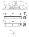
図1(A)を参照して、本発明による空力制御装置の一つの実施形態に於いては、路面R上を走行する車両の車両10の両側部の前輪12Fと後輪12Rとの間の下端縁11に於いて、その下方の領域を覆い、そこから車両10の車体の床下への空気流の進入を選択的に制限又は阻止する空力制御装置14が設けられる。空力制御装置14は、前輪12Fと後輪12Rとの間の下端縁11の実質的に全長に沿って延在し、下端縁11よりも下方に変位可能な遮蔽部材16と、下端縁11よりも上方に設けられ、遮蔽部材16を格納可能な筐体15とを含み、遮蔽部材16には、その両端(車両の前後方向に沿った前端と後端)近傍にて、ボールねじ19が固定された固定部17が装着され、更に、ボールねじ19は、後に説明される如く、CPUの制御指令に従って駆動ドライバによって動作される回転モータ18に連結される。そして、CPUは、車両が受ける風の向きを任意の形式にて検出する風向センサからの風向の検出値に従って、遮蔽部材16の上下方向の位置を決定し、その決定に従って、駆動ドライバを駆動して、遮蔽部材16を上下方向に変位させる。
Referring to FIG. 1 (A), in one embodiment of an aerodynamic control device according to the present invention, between a
より詳細には、遮蔽部材16は、図1(B)、(C)に模式的に描かれている如く、車体の下端縁11よりも上方にて筐体15に格納されて、下端縁11よりも下方の空間を“開けた”状態にする位置(全開位置−図1(B))と、下端縁11よりも下方に突出して延在して、下端縁11よりも下方の空間を“遮蔽”した状態にする位置(遮蔽位置−図1(C))との間で変位される。また、遮蔽部材16の変位は、例えば、回転モータ18がボールねじ19に対して相対的に回転することにより、ボールねじ19と固定部17とが上下に変位するのに伴って、遮蔽部材16上下に連動して変位する構成によって達成されてよい。なお、図1(D)の如く、遮蔽部材16は、ヒンジ軸19a周りに揺動されて、遮蔽位置と全開位置との間で変位されてもよい。
More specifically, the shielding
風向センサとしては、風向きを直接的に検出する任意のセンサ装置が利用されてよい。また、車両にしばしば装備されているジャイロセンサにより検出されたヨーレートとロールレートが逆位相であるか否かを判定する装置(図示せず)などであってもよい(ヨーレートとロールレートが逆位相であるとき、ロールレートの方向の横風が存在すると判定される。)。 As the wind direction sensor, any sensor device that directly detects the wind direction may be used. Further, it may be a device (not shown) for determining whether or not the yaw rate and roll rate detected by a gyro sensor often installed in a vehicle are in reverse phase (the yaw rate and roll rate are in reverse phase). When it is, it is determined that there is a cross wind in the direction of the roll rate.)
後述の走行中の車体周囲の空気の流れと車体が受ける圧力分布の説明に於いて、より詳細に理解される如く、遮蔽部材16が遮蔽位置にあるときの下端縁11よりも下方の空間を遮蔽する面積(遮蔽面積)は、車体の側部の下端縁11から車体の床下へ空気流が実質的に進入しないように設定されることが好ましい。また、遮蔽部材16が全開位置にあるときに下端縁11よりも下方の空間を開放する面積(開放面積)は、車体の側部の下端縁11から車体の床下へ空気流が有意な流量にて進入するように設定されることが好ましい。遮蔽部材16の遮蔽位置での遮蔽面積と全開位置での開放面積とは、車両の全体形状の設計を考慮して当業者に於いて任意に設定されてよい。
In the description of the air flow around the vehicle body and the pressure distribution received by the vehicle body, which will be described later, the space below the
図2(A)に模式的に描かれた本発明による空力制御装置の別の実施形態に於いては、図1(A)の場合と同様に、路面R上を走行する車両10の車体両側部の前輪12Fと後輪12Rとの間の下端縁11に於いて、その下方の領域を覆い、そこから車両10の車体の床下への空気流の進入を選択的に制限又は阻止する空力制御装置24が設けられる。しかしながら、空力制御装置24の場合には、前輪12Fと後輪12Rとの間の下端縁11に沿って、その前方部分に延在する遮蔽部材26と、下端縁11に沿ってその後方部分に延在する筐体25とが設けられる。筐体25の後端には、モータ28が配置され、かかるモータ28に対して下端縁11に沿って延在するボールねじ29が連結され、更に、ボールねじ29に対して固定部27を介して遮蔽部材26が装着される。かくして、モータ28が回転されると、ボールねじ29が回転し、その回転により固定部27の位置が移動して、これと共に、遮蔽部材26が車体の前後方向に変位されることとなる。モータ28に対しては、図1(A)の場合と同様に、車両が受ける風の向きを任意の形式にて検出する風向センサからの風向の検出値に従って、CPUから制御指令が与えられて、遮蔽部材26の前後方向の位置が制御されることとなる。
In another embodiment of the aerodynamic control device according to the present invention schematically illustrated in FIG. 2 (A), both sides of the
遮蔽部材26の変位について、図2(A)の実施形態の場合には、図2(B)、(C)から理解される如く、下端縁11よりも下方の空間を全長に亘って“遮蔽”した状態にする位置(遮蔽位置−図2(B))と、遮蔽部材26が後方の筐体25に格納されて下端縁11よりも下方の空間の前方部分のみを“開けた”状態にする位置(前方部分全開位置−図2(C))との間で変位される(即ち、図2(A)の場合には、筐体25も下端縁11よりも下方の空間を遮蔽する遮蔽部材の機能を果たす。)。遮蔽部材26が遮蔽位置にあるときの下端縁11よりも下方の空間を遮蔽する面積(遮蔽面積)は、図1(A)の場合と同様に、車体の側部の下端縁11から車体の床下へ空気流が実質的に進入しないように設定されることが好ましい。一方、遮蔽部材26が前方部分全開位置にあるときの下端縁11よりも下方の空間を開放する面積(前方部分開放面積)は、車体の側部の下端縁11の前方部分のみから車体の床下へ空気流が有意な流量にて進入するように設定されることが好ましい。遮蔽部材26の遮蔽位置での遮蔽面積と前方部分全開位置での開放面積とは、車両の全体形状の設計を考慮して当業者に於いて任意に設定されてよい。車体側部の下端縁11よりも下方の空間の前方部分の後端、即ち、前方部分と後方部分の境界の前後方向の位置は、概ね、車両の重心位置と一致していてよいが、車体の設計等によって重心位置より前又は後ろであってよい。また、遮蔽部材26は、図1(A)又は図1(D)の場合と同様に、上下方向に変位可能に構成されて、前方部分全開位置に於いては、遮蔽部材26が下端縁11よりも上方に格納されるようになっていてもよい。その場合、筐体25は、下端縁11よりも下方の空間の後方部分を遮蔽する機能を果たすべく固定された板状部材等に置き換えられてよい。
Regarding the displacement of the shielding
なお、上記の車体両側部の前輪12Fと後輪12Rとの間の遮蔽部材に加えて、前輪12Fより前方と後輪12Rより後方とに、前端可動式サイドスカート30と後端可動式サイドスカート40とが、それぞれ、設けられていてよい。これらの可動式サイドスカートの変位は、遮蔽部材16、26の変位と連動されてよく、遮蔽部材16、26が遮蔽位置にあるときには、下方へ突出され、遮蔽部材16、26が全開位置又は前方部分全開位置にあるときには、車体の下端よりも上方へ格納されてよい。(図2(A)の構成の場合には、後端可動式サイドスカート40は、遮蔽部材26の位置によらず、下方へ突出された状態のままに固定されてよい。)
In addition to the shielding member between the
上記の空力制御装置14、24の構成は、いずれも、陸上を走行する自動車等の車両だけでなく、空中に浮上して移動中の移動体、例えば、飛行可能な車両、航空機等に対しても適用可能であり、そのような場合も本発明の範囲に属することは理解されるべきである。
The configurations of the
空力制御装置の作動
既に触れた如く、上記の空力制御装置14、24の作動に於いては、いずれも、車両の走行中にセンサにより検出された車体の受ける空気流の偏揺角が所定の角度(角度閾値)を超えないときには、遮蔽部材16又は26は、遮蔽位置に設定される。所定の角度は、実質的に有意な横風が存在していないとみなすことのできる角度であり、実験的に又は理論的に設定されてよい。この状態に於いては、車体側部から下端縁11を通過して車体の下方の空間へ流入する空気流が制限され、後述の如く、車体の空力特性は、走行風が前後方向にのみ流れているときに空気抵抗が低減されるとともに、好適には、車体の下方の空間を通って車両の前方から後方に有意な空気流が流れることにより、ダウンフォースが発生される状態である。
Operation of the Aerodynamic Control Device As already mentioned , in the operation of the
一方、車体の受ける空気流の偏揺角が所定の角度を超えたとき、即ち、実質的に有意な横風が存在していると判定されたときには、CPUが駆動ドライバに制御指令を与え、これにより、モータが駆動されて、遮蔽部材16又は26は、全開位置又は前方部分全開位置へ変位される。この状態に於いては、車体側部から下端縁11を通過して車体の下方の空間へ流入する空気流が許されることとなり、後述の如く、車体の空力特性は、空気流中の横風の成分が車体の下方の空間へ逃されることにより、風下への回頭ヨーモーメント及び横力が低減され、好適には、車体の下方の空間を通って風上から風下に有意な空気流が流れることにより、ダウンフォースが発生される状態である。
On the other hand, when the yaw angle of the airflow received by the vehicle body exceeds a predetermined angle, that is, when it is determined that a substantially significant crosswind exists, the CPU gives a control command to the drive driver, Thus, the motor is driven, and the shielding
なお、上記の構成に於いて、空気流の偏揺角の値が陽に検出されなくてもよいことは理解されるべきである。単に、空気流に於いて有意な大きさの横風成分が存在するか否かを表す任意の指標が検出される構成に於いて、その指標が有意な大きさの横風成分の存在を示すことをもって、偏揺角が所定の角度が超えたと判断することが可能なので、そのような横風成分の存在を検出する指標に従って、上記の遮蔽部材の変位の制御が実行されてもよく、そのような場合も本発明の範囲に属する。 It should be understood that in the above configuration, the value of the airflow yaw angle need not be detected explicitly. In an arrangement in which an arbitrary index indicating whether or not there is a significant crosswind component in the air flow is detected, the index indicates the presence of a significant crosswind component. Since it is possible to determine that the yaw angle exceeds a predetermined angle, the displacement control of the shielding member may be executed according to an index for detecting the presence of such a crosswind component. Are also within the scope of the present invention.
空力制御の作用効果
以下、上記の空力制御装置14、24の作動による車体に対する空気流の具体的な作用効果について説明する。
Effects of Aerodynamic Control Hereinafter, specific actions and effects of the air flow on the vehicle body by the operation of the
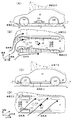
まず、図3(A)を参照して、遮蔽部材16又は26が遮蔽位置にあるとき、既に触れた如く、遮蔽部材16又は26が車体側部から下端縁11を通過して車体の下方の空間へ空気が流入する経路が遮断されるので、横風の不存在下では、空気流は、車体の上下と左右側部に沿って車体の前後方向に流れることとなり、車体10の床下に於ける空気流の乱れが少なく、空気抵抗が低い状態となる。その場合、車体に於いては、図中に示されている如き圧力分布が形成され(矢印は、力の向きを示している。)、上面にて車体を上昇させる作用(リフト)が発生する一方、底面(車体床下)にて車体を下方へ引っ張るダウンフォースDFが発生することとなる。
First, referring to FIG. 3 (A), when the shielding
しかしながら、図3(B)に例示されている如く、横風が発生すると、車両10は横風と走行風との合成風を受けることとなる。その場合、車体側部の下端縁11から車体の下方の空間への流路が遮断されていると、図に示されている如く、風上側では、空気流が車体側面に衝突し、風下側では、車体側面に沿って空気流が流れることとなる。そうすると、車体の風上側及び風下側の双方の車体表面に於いては、図示の如き、表面圧力分布が発生し、また、車体の前輪の周囲から流入した空気流が前輪の内側の構造体に衝突することにより、図示の如き、内部表面圧力分布が発生することとなる(図中の表面圧力分布及び内部表面圧力分布に於いて描かれている矢印は、力の向きを示している。)。そして、この状態で発生する表面圧力分布と内部表面圧力分布とによって、総じて、車体を風下側へ押す横力と車体の前方を風下側へ回頭する回頭ヨーモーメントとが生ずることとなる(詳細には、実際に作用する横力と回頭ヨーモーメントとは、表面圧力分布と内部表面圧力分布とを積分して得られる力とモーメントである。横風の存在下では、図示の如く、圧力分布に於いて、車両の前方領域の圧力が高く、空力中心CA(空気力による作用点)は、車両の前端から車両の全長の概ね1/4の距離となり、車両の重心CGに対して前方に位置するので、風下側への回頭ヨーモーメントが発生することとなる。)。即ち、車体側部の下端縁11から車体の下方の空間への流路を遮断した状態で、横風が発生すると、車体を風下側への横力と回頭ヨーモーメントとが発生し、車体の挙動安定性が低下されることとなる。
However, as illustrated in FIG. 3B, when a cross wind is generated, the
そこで、上記の如き横風が発生したときには、既に述べた如く、遮蔽部材16又は26が全開位置又は前方部分全開位置へ移動され、車体側部の下端縁11から車体の下方の空間への流路が開放され、風下側への押す横力と回頭ヨーモーメントとの低減が図られることとなる。
Therefore, when the cross wind as described above is generated, as already described, the shielding
具体的には、図1(A)の構成に於いては、遮蔽部材16を全開位置に変位させ、下端縁11よりも下方の空間が開放された状態とされ、これにより、図3(D)に描かれている如く、空気流が車体の下方の空間を流通することとなる。そうすると、風上側で車体側面に衝突する空気流と風下側で車体側面に沿って流れる空気流が低減されるので、図示の如く、表面圧力分布と内部表面圧力分布に於いて圧力が大幅に低減され、これにより、車体を風下側へ押す横力と車体の前方を風下側へ回頭する回頭ヨーモーメントが大幅に低減されることとなる(空力中心CAは、重心CGに相対的に近くなるため、横風によるヨーモーメントが低減される。なお、図3(C)に描かれている如く、車両の前後方向の圧力分布には、大きな差異は発生しない。)。
Specifically, in the configuration of FIG. 1 (A), the shielding
また、図2(A)の構成に於いては、遮蔽部材26を前方部分全開位置に変位させ、下端縁11よりも下方の空間の前方部分のみが開放された状態とされ、これにより、図4(B)に描かれている如く、空気流の一部が車体の前方部分の下方の空間を流通することとなる。そうすると、車体の前方部分に於いて、風上側で車体側面に衝突する空気流と風下側で車体側面に沿って流れる空気流が低減されるので、図示の如く、車体の前方部分の表面圧力分布と内部表面圧力分布に於いて圧力が低減され、これにより、車体を風下側へ押す横力と車体の前方を風下側へ回頭する回頭ヨーモーメントが低減されることとなる。更に、図4(B)の構成の場合には、下端縁11よりも下方の空間の後方部分に於いては、遮蔽部材26として機能する筐体25が存在しているので、その筐体25に空気流が衝突し、これにより、後輪近傍に於いて、そこに於ける表面圧力分布と内部表面圧力分布に示されている如く、風下側への横力が発生することとなる。かかる横力は、車両の重心CGの後方に作用することとなるので、これにより、車体の後方を風下へ向けるヨーモーメント、即ち、横風による回頭ヨーモーメントを打ち消す方向のアンチヨーモーメントが発生されることとなる。
Further, in the configuration of FIG. 2A, the shielding
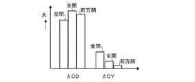
図5は、上記の図3(B)(全閉)、図3(D)(全開)及び図4(B)(前方開)の場合の空気抵抗係数ΔCDとヨーモーメント係数ΔCYとの差異を模式的に示した図である(空気抵抗係数ΔCD及びヨーモーメント係数ΔCYは、それぞれ、空気流により車体に於いて生ずる前後方向抗力及び回頭ヨーモーメントを無次元化した値である。)。同図を参照して、空気抵抗係数ΔCDについては、図3(D)(全開)及び図4(B)(前方開)の場合には、車体側部の下端縁11から車体下方への空気流の流入があるために、図3(B)(全閉)の場合に比して増大するが、車体側部に対する空気流の衝突の低減と車体の周囲を水平方向に沿って流れる空気流の低減によって、ヨーモーメント係数ΔCYが低減されることとなる。また、図4(B)の場合には、上記の如く、車両後方部分に於いて横風による回頭ヨーモーメントに対するアンチヨーモーメントが発生するので、図3(D)(全開)の場合よりも、ヨーモーメント係数ΔCYが更に低減されることとなる。
FIG. 5 shows the difference between the air resistance coefficient ΔCD and the yaw moment coefficient ΔCY in the case of FIG. 3 (B) (fully closed), FIG. 3 (D) (fully opened) and FIG. 4 (B) (forward opened). It is a diagram schematically showing (the air resistance coefficient ΔCD and the yaw moment coefficient ΔCY are values obtained by making the longitudinal drag and the turning yaw moment generated in the vehicle body by the air flow dimensionless, respectively). Referring to the figure, with respect to the air resistance coefficient ΔCD, in the case of FIG. 3D (fully open) and FIG. 4B (forward open), the air from the
上記の本発明の空力制御装置は、既に述べた如く、空中に浮上して移動中の移動体、例えば、飛行可能な車両、航空機等に対しても適用可能であり、その場合にも、図3〜5にて説明された作用効果と略同様の左右効果が得られる。図6(A)〜(D)は、図1(A)の構成を空中ホバリング中の移動体に適用した場合の胴体の受ける圧力の分布と空気流の流れを示しており、図3(A)〜(D)の場合と比較して、移動体の下方に路面が存在しないため、移動体の上下方向の表面圧力分布の形状は異なるところ、移動体の水平方向の表面圧力分布と内部表面圧力分布は同様となる。即ち、下端縁11よりも下方の空間が開放され、胴体の下方の空間への空気流の流通が許されることにより、胴体を風下側へ押す横力と胴体の前方を風下側へ回頭する回頭ヨーモーメントが大幅に低減されることとなる。なお、図示していないが、空中ホバリング中の移動体に図2(A)の構成を適用した場合には、図4(B)と略同様の表面圧力分布と内部表面圧力分布が得られ、胴体を風下側へ押す横力と胴体の前方を風下側へ回頭する回頭ヨーモーメントとの低減と、横風による回頭ヨーモーメントに対するアンチヨーモーメントの発生の作用効果が得られることとなる。
As described above, the aerodynamic control device of the present invention can also be applied to a moving object that is levitating and moving in the air, for example, a flightable vehicle, an aircraft, and the like. The left and right effects substantially the same as the effects described in 3 to 5 are obtained. 6 (A) to 6 (D) show the distribution of pressure received by the fuselage and the flow of air flow when the configuration of FIG. 1 (A) is applied to a moving body in the air hovering. ) To (D), since there is no road surface below the moving body, the shape of the surface pressure distribution in the vertical direction of the moving body is different. The pressure distribution is the same. That is, the space below the
かくして、上記の構成によれば、移動体の受ける空気流に於いて偏揺角が所定値を超えないときには、車体又は胴体の下端縁11より下方の空間への空気流の流入を制限し、これにより、車体又は胴体のリフトの低減を図る一方、偏揺角が所定値を超えたときには、車体又は胴体の下端縁11より下方の空間への空気流の流入を許すことによって、車体又は胴体を風下側へ押す横力と車体又は胴体の前方を風下側へ回頭する回頭ヨーモーメントとの低減が図られることとなる。
Thus, according to the above configuration, when the yaw angle does not exceed a predetermined value in the air flow received by the moving body, the inflow of the air flow into the space below the
以上の説明は、本発明の実施の形態に関連してなされているが、当業者にとつて多くの修正及び変更が容易に可能であり、本発明は、上記に例示された実施形態のみに限定されるものではなく、本発明の概念から逸脱することなく種々の装置に適用されることは明らかであろう。 Although the above description has been made in relation to the embodiment of the present invention, many modifications and changes can be easily made by those skilled in the art, and the present invention is limited to the embodiment exemplified above. It will be apparent that the invention is not limited and applies to various devices without departing from the inventive concept.
Claims (9)
前記移動体の胴体の両側部の前輪と後輪との間の下端縁に、その更に下方へ前記胴体の下端縁より下方の空間を覆うように延在して前記胴体の底部の空気流の進入を制限することが可能な可動式の遮蔽部材と、
前記遮蔽部材の位置を移動して前記遮蔽部材が前記胴体の下端縁より下方の空間を覆う遮蔽面積を制御する制御手段とを含み、前記制御手段が前記移動体の受ける空気流の方向に基づいて前記遮蔽部材の前記遮蔽面積を制御する装置。 An aerodynamic control device for a moving body,
The lower end edge between the front wheel and the rear wheel on both sides of the body of the moving body extends further below to cover the space below the lower end edge of the body, and the air flow at the bottom of the body A movable shielding member capable of restricting entry; and
Control means for controlling the shielding area in which the shielding member covers the space below the lower end edge of the body by moving the position of the shielding member, and the control means is based on the direction of the air flow received by the moving body. A device for controlling the shielding area of the shielding member.
4. The apparatus according to claim 1, wherein the shielding member is disposed in a space below the lower edge between the front wheel and the rear wheel on both sides of the body in the front-rear direction of the moving body. A device that is movable between a front part full open position in which the front part is fully open and a shield position that shields a predetermined range of the space below the lower edge.
Priority Applications (2)
| Application Number | Priority Date | Filing Date | Title |
|---|---|---|---|
| JP2015031168A JP2016150741A (en) | 2015-02-19 | 2015-02-19 | Movable body aerodynamic control device |
| US15/041,796 US20160244107A1 (en) | 2015-02-19 | 2016-02-11 | Aerodynamic control device of a mobile body |
Applications Claiming Priority (1)
| Application Number | Priority Date | Filing Date | Title |
|---|---|---|---|
| JP2015031168A JP2016150741A (en) | 2015-02-19 | 2015-02-19 | Movable body aerodynamic control device |
Publications (1)
| Publication Number | Publication Date |
|---|---|
| JP2016150741A true JP2016150741A (en) | 2016-08-22 |
Family
ID=56693419
Family Applications (1)
| Application Number | Title | Priority Date | Filing Date |
|---|---|---|---|
| JP2015031168A Pending JP2016150741A (en) | 2015-02-19 | 2015-02-19 | Movable body aerodynamic control device |
Country Status (2)
| Country | Link |
|---|---|
| US (1) | US20160244107A1 (en) |
| JP (1) | JP2016150741A (en) |
Cited By (2)
| Publication number | Priority date | Publication date | Assignee | Title |
|---|---|---|---|---|
| US10315713B2 (en) | 2017-04-17 | 2019-06-11 | Ford Global Technologies, Llc | Side splitter and splitter assembly with dive plane feature |
| US10351183B2 (en) | 2017-04-17 | 2019-07-16 | Ford Global Technologies, Llc | Side splitter, splitter assembly and method of improving stability and peak cornering speed of a motor vehicle |
Families Citing this family (11)
| Publication number | Priority date | Publication date | Assignee | Title |
|---|---|---|---|---|
| US10189517B2 (en) | 2014-03-21 | 2019-01-29 | Magna Exteriors, Inc. | Deployable aerodynamic side panel system |
| US9669885B1 (en) * | 2015-12-04 | 2017-06-06 | GM Global Technology Operations LLC | Regulation of downforce on a vehicle body via control of an airstream through a vehicle duct |
| US9975585B2 (en) * | 2016-07-12 | 2018-05-22 | GM Global Technology Operations LLC | Active dive-planes for a motor vehicle |
| US20180022403A1 (en) * | 2016-07-20 | 2018-01-25 | GM Global Technology Operations LLC | Method for controlling vehicle downforce |
| US9975490B1 (en) * | 2017-02-13 | 2018-05-22 | AISIN Technical Center of America, Inc. | Side step apparatus and actuation mechanism |
| US9994267B1 (en) * | 2017-04-12 | 2018-06-12 | GM Global Technology Operations LLC | Active side-skirts for a motor vehicle |
| US10471914B2 (en) * | 2017-10-24 | 2019-11-12 | GM Global Technology Operations LLC | Deployable debris protection device for an automotive vehicle |
| CN110114260A (en) * | 2017-11-30 | 2019-08-09 | 沈国忠 | The automotive system mobile for automobile component |
| CN113492926A (en) * | 2020-03-20 | 2021-10-12 | 广州汽车集团股份有限公司 | Car water conservancy diversion structure and car |
| US11679823B2 (en) | 2021-01-06 | 2023-06-20 | Honda Motor Co., Ltd. | Retractable aerodynamic side skirts for vehicles |
| US11731709B1 (en) * | 2022-12-08 | 2023-08-22 | Toyota Motor Engineering & Manufacturing North America, Inc | Aero cladding system for a vehicle |
Citations (5)
| Publication number | Priority date | Publication date | Assignee | Title |
|---|---|---|---|---|
| JPH0295987A (en) * | 1988-09-30 | 1990-04-06 | Toyota Motor Corp | Traverse wind controlling method for vehicle |
| JPH04342675A (en) * | 1991-05-21 | 1992-11-30 | Nissan Motor Co Ltd | Method for stabilizing vehicle against side wind |
| JPH0620174U (en) * | 1992-05-07 | 1994-03-15 | 一彦 香味 | Side spoiler device |
| JPH06305452A (en) * | 1993-04-26 | 1994-11-01 | Mazda Motor Corp | Travel stabilizer and travel stabilizing air spoiler set for automobile |
| JP2008260406A (en) * | 2007-04-12 | 2008-10-30 | Toyota Motor Corp | Aerodynamic control device for vehicle |
Family Cites Families (2)
| Publication number | Priority date | Publication date | Assignee | Title |
|---|---|---|---|---|
| US6209947B1 (en) * | 1998-01-02 | 2001-04-03 | Daimlerchrysler Corporation | Adjustable aerodynamic system for a motor vehicle |
| US10189517B2 (en) * | 2014-03-21 | 2019-01-29 | Magna Exteriors, Inc. | Deployable aerodynamic side panel system |
-
2015
- 2015-02-19 JP JP2015031168A patent/JP2016150741A/en active Pending
-
2016
- 2016-02-11 US US15/041,796 patent/US20160244107A1/en not_active Abandoned
Patent Citations (5)
| Publication number | Priority date | Publication date | Assignee | Title |
|---|---|---|---|---|
| JPH0295987A (en) * | 1988-09-30 | 1990-04-06 | Toyota Motor Corp | Traverse wind controlling method for vehicle |
| JPH04342675A (en) * | 1991-05-21 | 1992-11-30 | Nissan Motor Co Ltd | Method for stabilizing vehicle against side wind |
| JPH0620174U (en) * | 1992-05-07 | 1994-03-15 | 一彦 香味 | Side spoiler device |
| JPH06305452A (en) * | 1993-04-26 | 1994-11-01 | Mazda Motor Corp | Travel stabilizer and travel stabilizing air spoiler set for automobile |
| JP2008260406A (en) * | 2007-04-12 | 2008-10-30 | Toyota Motor Corp | Aerodynamic control device for vehicle |
Cited By (2)
| Publication number | Priority date | Publication date | Assignee | Title |
|---|---|---|---|---|
| US10315713B2 (en) | 2017-04-17 | 2019-06-11 | Ford Global Technologies, Llc | Side splitter and splitter assembly with dive plane feature |
| US10351183B2 (en) | 2017-04-17 | 2019-07-16 | Ford Global Technologies, Llc | Side splitter, splitter assembly and method of improving stability and peak cornering speed of a motor vehicle |
Also Published As
| Publication number | Publication date |
|---|---|
| US20160244107A1 (en) | 2016-08-25 |
Similar Documents
| Publication | Publication Date | Title |
|---|---|---|
| JP2016150741A (en) | Movable body aerodynamic control device | |
| US9714058B2 (en) | Actively controlled spoiler for a motor vehicle | |
| US10035548B2 (en) | Active spoiler for a motor vehicle | |
| US8702152B1 (en) | Deployable front air dam | |
| CN105857415B (en) | Compact and efficient system for rapidly raising and slowly lowering an air baffle | |
| US9932074B2 (en) | Active vehicle skirt panel and the method of controlling the same | |
| US9487251B2 (en) | Vehicle having an integrated air curtain and brake cooling duct | |
| EP3177508B1 (en) | Modifying aerodynamic performance of a vehicle | |
| JPH0631014B2 (en) | Aerodynamic vehicle | |
| US20150149046A1 (en) | System and method of controlling adjustable spoiler | |
| US20170240225A1 (en) | Modifying aerodynamic performance of a vehicle | |
| US20140265435A1 (en) | Bumper with enhanced cooling and associated drag reduction device | |
| CN108463395A (en) | Aerodynamics arrangement for deflecting for motor vehicle wheel | |
| US4318565A (en) | Stator apparatus for a moving vehicle | |
| JP5585180B2 (en) | Moving body | |
| US8727423B2 (en) | Self-drafting device for sub-sonic terrestrial vehicles | |
| JP2008260406A (en) | Aerodynamic control device for vehicle | |
| US10518815B2 (en) | Air deflector assembly for an automatic vehicle | |
| JP2018135054A (en) | Air resistance reduction device for vehicle and vehicle | |
| WO2013022388A1 (en) | Aerodynamic system for reducing wind resistance of a vehicle | |
| KR20160118189A (en) | Side skirt structure for car | |
| CN111688474A (en) | Method and apparatus for a mobile heat exchanger | |
| EP3147184B1 (en) | Aerodynamic vehicle structure | |
| RU149359U1 (en) | EXTENDABLE FRONT SPOILER FOR VEHICLE | |
| JP2010115937A (en) | Load-carrying platform structure for wing body type truck |
Legal Events
| Date | Code | Title | Description |
|---|---|---|---|
| A621 | Written request for application examination |
Free format text: JAPANESE INTERMEDIATE CODE: A621 Effective date: 20160609 |
|
| A977 | Report on retrieval |
Free format text: JAPANESE INTERMEDIATE CODE: A971007 Effective date: 20170208 |
|
| A131 | Notification of reasons for refusal |
Free format text: JAPANESE INTERMEDIATE CODE: A131 Effective date: 20170307 |
|
| A02 | Decision of refusal |
Free format text: JAPANESE INTERMEDIATE CODE: A02 Effective date: 20170912 |