JP2016127620A - motor - Google Patents
motor Download PDFInfo
- Publication number
- JP2016127620A JP2016127620A JP2014264195A JP2014264195A JP2016127620A JP 2016127620 A JP2016127620 A JP 2016127620A JP 2014264195 A JP2014264195 A JP 2014264195A JP 2014264195 A JP2014264195 A JP 2014264195A JP 2016127620 A JP2016127620 A JP 2016127620A
- Authority
- JP
- Japan
- Prior art keywords
- holder
- bearing
- mounting plate
- bearing holder
- motor
- Prior art date
- Legal status (The legal status is an assumption and is not a legal conclusion. Google has not performed a legal analysis and makes no representation as to the accuracy of the status listed.)
- Pending
Links
Images


Abstract
Description
本発明は、モータに関する。 The present invention relates to a motor.
従来のモータの構造については、例えば、特開2006−238567号公報に開示されている。当該公報では、ブラケットとハウジングとの間にモータ基板、固定子、及びスペーサが、ハウジングと芯出しされて積層される。そして、ハウジングとブラケットをかしめて弾性変形するスペーサの反力により、モータ基板及び固定子がハウジングとブラケットとの間で固定される。
モータの製造時には、出荷先の違いや仕様の違いによって、軸受を保持する部材に対してその外側に配置される板状の部材の軸方向の位置を、変更したい場合がある。しかしながら、特開2006−238567号公報の構造では、軸受を保持する部材(ハウジング)に対して、その外側に配置される板状の部材(ブラケット)の高さ方向の位置を任意に変更することができない。 At the time of manufacturing the motor, there are cases where it is desired to change the axial position of the plate-like member arranged outside the member holding the bearing, depending on the shipping destination and the specification. However, in the structure of Japanese Patent Application Laid-Open No. 2006-238567, the position in the height direction of a plate-like member (bracket) arranged outside the member (housing) that holds the bearing is arbitrarily changed. I can't.
軸受を保持する部材を円筒状とし、それに対して板状の部材を圧入にて固定すれば、軸受を保持する部材に対する板状の部材の軸方向の位置を、任意に変更することができる。ただし、これらの部材は、双方ともプレスにより作製されることが多い。このため、プレス時の加工誤差によって、圧入の締め代にばらつきが発生する。また、これらの部材がプレス以外の工法で作製される場合にも、両部材の加工誤差が重なることにより、圧入の締め代にばらつきが生じる場合がある。圧入の締め代が大き過ぎると、部材の変形によって、軸受やステータなどの他の部品の位置精度が悪化する虞がある。 If the member holding the bearing is cylindrical, and the plate-like member is fixed by press-fitting thereto, the position of the plate-like member in the axial direction relative to the member holding the bearing can be arbitrarily changed. However, both of these members are often produced by pressing. For this reason, variations in press-fit tightening allowances occur due to processing errors during pressing. In addition, even when these members are manufactured by a method other than pressing, the press-fitting tightening allowance may vary due to overlapping processing errors of both members. If the press-fitting tightening margin is too large, the positional accuracy of other components such as a bearing and a stator may be deteriorated due to deformation of the member.
本発明は、軸受を保持する軸受ホルダと、軸受ホルダの径方向外側に固定される取り付け板とを有するモータにおいて、圧入の締め代に依存することなく、軸受ホルダと取付板との固定強度を向上させることができる構造を提供することである。 The present invention relates to a motor having a bearing holder for holding a bearing and a mounting plate fixed to the outer side in the radial direction of the bearing holder, so that the fixing strength of the bearing holder and the mounting plate can be increased without depending on the press-fit tightening allowance. It is to provide a structure that can be improved.
本願の例示的な第1発明は、上下に延びる中心軸の周囲において、軸方向に略円筒状に延びる軸受ホルダと、前記軸受ホルダの径方向内側に固定された軸受部と、前記軸受ホルダの径方向外側に固定され、前記中心軸に対して直交する方向に広がる取付板と、前記取付板の上面または下面に配置された回路基板と、前記取付板より上方において、前記軸受ホルダの径方向外側に固定されたステータコアと、前記ステータコアに取り付けられたコイルと、前記軸受部により回転可能に支持されるシャフトと、前記シャフトとともに回転するマグネットと、を有し、前記取付板は、前記中心軸と同軸に設けられた円孔を有する板状部と、前記円孔の縁から軸方向に突出するバーリング部と、を有し、前記軸受ホルダの外周面は、前記バーリング部に接触する接触領域を有し、前記軸受ホルダの外周面または前記取付板の表面は、前記接触領域の付近に、前記接触領域の広さよりも細かいピッチで凹凸を繰り返す粗面部を有するモータである。 An exemplary first invention of the present application includes: a bearing holder extending in a substantially cylindrical shape in the axial direction around a central axis extending vertically; a bearing portion fixed on a radially inner side of the bearing holder; and A mounting plate that is fixed radially outward and extends in a direction perpendicular to the central axis, a circuit board disposed on the upper surface or the lower surface of the mounting plate, and a radial direction of the bearing holder above the mounting plate A stator core fixed to the outside; a coil attached to the stator core; a shaft rotatably supported by the bearing; and a magnet that rotates together with the shaft; and the attachment plate includes the central axis A plate-like portion having a circular hole provided coaxially, and a burring portion that protrudes in an axial direction from an edge of the circular hole, and an outer peripheral surface of the bearing holder includes the burring portion It has a contact region contacting the outer peripheral surface or the surface of the mounting plate of the bearing holder, in the vicinity of the contact area, is a motor having a rough surface portion to repeat irregularities with fine pitch than width of the contact area.
本願の例示的な第1発明によれば、粗面部の細かい凹凸によって、軸受ホルダと取付板との固定強度を向上させることができる。 According to the exemplary first invention of the present application, the fixing strength between the bearing holder and the mounting plate can be improved by the fine unevenness of the rough surface portion.
以下、本発明の例示的な実施形態について、図面を参照しつつ説明する。なお、本願では、モータの中心軸と平行な方向を「軸方向」、モータの中心軸に直交する方向を「径方向」、モータの中心軸を中心とする円弧に沿う方向を「周方向」、とそれぞれ称する。また、本願では、軸方向を上下方向とし、取付板に対してステータコア側を「上」として、各部の形状や位置関係を説明する。ただし、これは、あくまで説明の便宜のために上下を定義したものであって、本発明に係るモータの使用時の向きを限定するものではない。 Hereinafter, exemplary embodiments of the present invention will be described with reference to the drawings. In this application, the direction parallel to the central axis of the motor is the “axial direction”, the direction orthogonal to the central axis of the motor is the “radial direction”, and the direction along the arc centered on the central axis of the motor is the “circumferential direction”. , Respectively. Further, in the present application, the shape and positional relationship of each part will be described with the axial direction being the vertical direction and the stator core side being “up” with respect to the mounting plate. However, this is defined as upper and lower for convenience of explanation, and does not limit the direction when the motor according to the present invention is used.
<1.モータの全体構成>
図1は、本発明の一実施形態に係るモータ1の縦断面図である。本実施形態のモータ1は、プリンタやコピー機等のOA機器に搭載され、ローラ等の駆動部を動作させるために使用される。ただし、本発明のモータは、OA機器以外の用途に使用されるものであってもよい。例えば、本発明のモータは、自動車等の輸送機器、家電製品、医療機器、ディスクドライブ、送風ファン等に使用されて、種々の駆動力を発生させるものであってもよい。
<1. Overall configuration of motor>
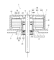
FIG. 1 is a longitudinal sectional view of a
図1に示すように、モータ1は、静止部2と回転部3とを有する。静止部2は、駆動対象となる装置の枠体に対して、相対的に静止している。回転部3は、静止部2に対して、回転可能に支持されている。
As shown in FIG. 1, the
本実施形態の静止部2は、取付板21、回路基板22、軸受ホルダ23、軸受部24、スペーサ25、ステータコア26、およびコイル27を有する。
The
取付板21は、中心軸9に対して直交する方向に広がる板材である。取付板21の材料には、回路基板22より剛性が高い金属が、使用される。例えば、亜鉛めっき鋼板、SUS、アルミニウム合金などの金属板を、プレス加工することにより、取付板21が形成される。取付板21は、駆動対象となる装置の枠体に、固定される。
The
取付板21は、中心軸9と同軸に設けられた円孔である第1挿入孔210を有する板状部を有する。第1挿入孔210には、軸受ホルダ23が挿入される。取付板21の板状部は、バーリング部211、内側板状部212、段差部213、および外側板状部214を有する。バーリング部211は、第1挿入孔210の縁から軸方向上側へ向けて、略円筒状に突出している。内側板状部212は、バーリング部211の下端部から、径方向外側へ向けて広がっている。段差部213は、内側板状部212の外周部から、径方向外側かつ下側へ向けて、斜めに延びている。また、外側板状部214は、段差部213の下端部から、さらに径方向外側へ向けて広がっている。
The
本実施形態の取付板21は、軸受ホルダ23を取り囲む外囲部材の一例である。軸受ホルダ23は、バーリング部211の径方向内側に、圧入されている。これにより、取付板21が、軸受ホルダ23の径方向外側に、固定されている。軸受ホルダ23の圧入時には、段差部213が撓むことにより、外側板状部214に掛かる圧入荷重が低減される。その結果、圧入時における外側板状部214の変形が、抑制される。
The
また、後述するロータホルダ32に偏荷重が掛かった場合、シャフト31にラジアル荷重が掛かり、荷重が軸受部24に伝達され、取付板21に荷重が掛かる。しかしながら、本実施形態の取付板21は、段差部213を有している。このため、当該荷重が、バーリング部211の下端部だけではなく、段差部213の上端部および下端部にも、分散して作用する。したがって、バーリング部211の下端部に対する荷重による応力が、低減される。その結果、駆動に伴うバーリング部211の変形が、抑制される。
Further, when an unbalanced load is applied to the
回路基板22は、取付板21の上面または下面に配置される。本実施形態においては、回路基板22は、内側板状部212の上面に、配置されている。回路基板22には、例えば、ガラスエポキシ基板や、紙フェノール基板が、使用される。また、回路基板22には、コイル27に駆動電流を供給するための電子回路が、実装されている。特に、本実施形態では、取付板21の段差部213が、回路基板22から離れる方向へ延びている。したがって、段差部213および外側板状部214の上面と、回路基板22の下面との間に、隙間が介在する。このため、回路基板22の上面だけではなく、回路基板22の下面にも、電子部品を配置することができる。
The
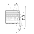
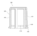
図2は、軸受ホルダ23の斜視図である。図3は、軸受ホルダ23の縦断面図である。図2および図3に示すように、軸受ホルダ23は、筒状部40と、フランジ部50とを有する。筒状部40は、中心軸9の周囲において、軸方向に略円筒状に延びている。フランジ部50は、筒状部40の下端部から、径方向外側へ向けて広がっている。
FIG. 2 is a perspective view of the bearing
筒状部40は、複数のホルダ凸部41、複数のホルダ凹部42、複数の傾斜部43、および挿入部44を、有する。ホルダ凸部41の径方向外側の面は、ホルダ凹部42の径方向外側の面より、径方向外側に位置する。また、ホルダ凹部42の径方向内側の面は、ホルダ凸部41の径方向内側の面より、径方向内側に位置する。また、複数のホルダ凸部41と、複数のホルダ凹部42とは、周方向に交互に設けられている。
The
各ホルダ凸部41の径方向外側の面は、取付板21のバーリング部211の内周面に、接触する。すなわち、各ホルダ凸部41の径方向外側の面は、バーリング部211に接触する接触領域410を含む。さらに、少なくともホルダ凸部41の径方向外側の面が、粗面部230を含む。この構成により、ホルダ凸部41とホルダ凹部42を有する軸受ホルダ23において、軸受ホルダ23と、取付板21との締結強度を向上させることができる。また、各ホルダ凸部41の径方向外側の面は、接触領域410より軸方向上側において、ステータコア26のコアバック261の内周面に、接触する。一方、各ホルダ凹部42の径方向内側の面は、少なくとも部分的に軸受部24に接触する。本実施形態においては、各ホルダ凹部42の径方向内側の面が、後述する第1軸受241および第2軸受242の各外輪に、接触する。なお、本実施形態においては、粗面部230は、ホルダ凸部41の径方向外側の面に形成されているが、粗面部230は、必ずしも軸受ホルダ23に形成されている必要はない。例えば、取付板21の表面に粗面部230が形成されていてもよい。
The radially outer surface of each
複数の傾斜部43は、ホルダ凸部41とホルダ凹部42との間に位置する。各傾斜部43は、ホルダ凸部41の周方向の端縁と、ホルダ凹部42の周方向の端縁とを、繋いでいる。また、各傾斜部43は、径方向および周方向に対して、斜めに広がっている。その結果、ホルダ凸部41の径方向外側の面と、ホルダ凹部42の径方向内側の面とが、異なる周方向位置に配置されている。
The plurality of
挿入部44は、ホルダ凸部41およびホルダ凹部42の上側に、設けられている。挿入部44の外径は、全周に亘って、ホルダ凸部41の外径より小さい。取付板21に軸受ホルダ23を圧入するときには、まず、バーリング部211の内側に、挿入部44を挿入する。また、ステータコア26に軸受ホルダ23を圧入するときにも、まず、コアバック261の内側に、挿入部44を挿入する。このようにすれば、バーリング部211およびコアバック261に対して、軸受ホルダ23を、容易に同軸に位置決めできる。
The
本実施形態の軸受ホルダ23は、金属製のプレス加工品である。軸受ホルダ23の材料には、例えば、亜鉛めっき鋼板、SUS、アルミニウム合金などの金属が用いられる。軸受ホルダ23を製造するときには、まず、金属板に絞り加工を行うことによって、筒状部40を形成する。その後、フランジ部50の外周部を打ち抜いて、軸受ホルダ23を得る。その場合、絞り加工により形成された筒状部40の外周面より、打ち抜きにより形成されたフランジ部50の外周部の方が、高い寸法精度を得やすい。したがって、駆動対象となる装置にモータ1を組み付けるときには、フランジ部50を利用して、当該装置に対するモータ1の位置決めを行うとよい。
The bearing
なお、本発明の軸受ホルダは、切削や鋳造等の他の工法により得られたものであってもよい。 The bearing holder of the present invention may be obtained by other methods such as cutting and casting.
図1に戻る。軸受部24は、回転部3側のシャフト31を回転可能に支持する機構である。本実施形態の軸受部24は、第1軸受241および第2軸受242を有する。第2軸受242は、第1軸受241より下側に配置されている。本実施形態の第1軸受241および第2軸受242には、球体を介して外輪と内輪とを相対回転させるボールベアリングが、使用されている。ただし、ボールベアリングに代えて、含油焼結軸受などの他方式の軸受が、使用されていてもよい。また、軸受部24を構成する軸受の数は、1つであってもよく、3つ以上であってもよい。
Returning to FIG. The bearing
第1軸受241および第2軸受242の各外輪は、軸受ホルダ23の径方向内側に、固定されている。具体的には、各外輪の外周面と、ホルダ凹部42の径方向内側の面とが、接触している。一方、第1軸受241および第2軸受242の各内輪は、シャフト31に固定されている。
The outer rings of the
図1に示すように、本実施形態の第1軸受241および第2軸受242には、外径の等しい軸受が使用されている。このようにすれば、第1軸受241と第2軸受242とに、共通の軸受を使用でき、部品の互換性が向上する。また、ホルダ凹部42の径方向内側の面は、第1軸受241の径方向外側の位置から、第2軸受242の径方向外側の位置まで、略同一の径で軸方向に連続している。このため、ホルダ凹部42を、絞り加工で容易に得ることができる。
As shown in FIG. 1, bearings having the same outer diameter are used for the
スペーサ25は、第1軸受241と第2軸受242との間に、配置されている。スペーサ25の上端部は、第1軸受241の外輪に接触する。また、スペーサ25の下端部は、第2軸受242の外輪に接触する。これにより、第1軸受241と第2軸受242との軸方向の間隔が、保たれている。
The
ステータコア26は、取付板21より上方において、軸受ホルダ23の径方向外側に固定されている。ステータコア26は、ケイ素鋼板等の電磁鋼板を軸方向に積層した積層鋼板により、形成される。ステータコア26は、円環状のコアバック261と、コアバック261から径方向外側へ向けて突出した複数のティース262と、を有する。また、ステータコア26は、コアバック261の径方向内側に、軸受ホルダ23が挿入される第2挿入孔260を有する。
The
本実施形態のステータコア26は、軸受ホルダ23を取り囲む外囲部材の一例である。軸受ホルダ23は、コアバック261の径方向内側に、圧入されている。これにより、ステータコア26が、軸受ホルダ23の径方向外側に固定されている。
The
複数のティース262は、周方向に略等間隔に配列されている。各ティース262には、コイル27が取り付けられている。コイル27は、各ティース262に巻き付けられた導線により、構成される。
The plurality of
本実施形態の回転部3は、シャフト31と、ロータホルダ32と、マグネット33と、を有する。
The rotating unit 3 according to the present embodiment includes a
シャフト31は、中心軸9に沿って延びる柱状の部材である。シャフト31の材料には、例えば、ステンレス等の金属が使用される。シャフト31は、軸受部24に支持されつつ、中心軸9を中心として回転する。シャフト31の上端部は、第1軸受241より上方へ突出している。また、シャフト31の下端部は、第2軸受242より下方へ突出している。シャフト31の下端部は、ギア等の動力伝達機構を介して、OA機器の駆動部に連結される。
The
ロータホルダ32は、シャフト31とともに回転する金属製の部材である。ロータホルダ32は、内側円筒部320、天板部321、および外側円筒部322を有する。天板部321は、コイル27の上方において、略平板状に広がっている。内側円筒部320は、天板部321の内周部から上方へ向けて、円筒状に延びている。内側円筒部320の内周面は、シャフト31の上端部付近の外周面に固定される。外側円筒部322は、天板部321の外周部から下方へ向けて、円筒状に延びている。
The
マグネット33は、ロータホルダ32の外側円筒部322の内周面に、固定されている。マグネット33は、シャフト31およびロータホルダ32とともに、回転する。マグネット33には、例えば、フェライトマグネットや、ネオジムマグネットが使用される。本実施形態のマグネット33は、円環状である。マグネット33の内周面は、ステータコア26の複数のティース262と、径方向に対向する。また、マグネット33の内周面には、N極とS極とが、周方向に交互に着磁されている。
The magnet 33 is fixed to the inner peripheral surface of the outer
なお、円環状のマグネット33に代えて、複数のマグネットが使用されていてもよい。その場合、N極の磁極面とS極の磁極面とが交互に並ぶように、複数のマグネットが、周方向に配列されていればよい。 A plurality of magnets may be used instead of the annular magnet 33. In this case, a plurality of magnets may be arranged in the circumferential direction so that the N pole magnetic pole surface and the S pole magnetic pole surface are alternately arranged.
回路基板22を介してコイル27に駆動電流を与えると、ステータコア26の各ティース262に、径方向の磁束が生じる。そして、ティース262とマグネット33との間の磁束の作用によって、周方向のトルクが発生する。その結果、静止部2に対して回転部3が、中心軸9を中心として回転する。回転部3が回転すると、シャフト31に連結された駆動部に、動力が伝達される。
When a drive current is applied to the
<2.軸受ホルダのブラスト加工について>
本実施形態の軸受ホルダ23の表面には、ショットブラストまたはサンドブラストと称されるブラスト加工が施される。これにより、図3中の拡大図のように、軸受ホルダ23の表面に細かい凹凸が形成される。ブラスト加工を行うときには、例えば、軸受ホルダ23を収容した容器内に研磨材を入れて撹拌させたり、軸受ホルダ23の表面に向けて研磨材を含む圧縮空気を吹き付けたりする。本実施形態では、軸受ホルダ23の表面全体に、このようなブラスト加工が施される。よって、軸受ホルダ23の外周面も粗面部230を含む。これにより、軸受ホルダ23の外周面に、細かい凹凸を有する粗面部230が形成される。このように、ブラスト加工を用いて粗面部230を形成すれば、安価かつ簡易な加工方法によって、軸受ホルダ23と取付板21とを強固に固定できる。
<2. About blasting of bearing holders>
The surface of the bearing
粗面部230は、軸受ホルダ23の接触領域410の広さよりも十分に細かいピッチで、凹凸を繰り返す。ブラスト加工後の粗面部230の摩擦係数は、ブラスト加工前の摩擦係数よりも高くなる。したがって、軸受ホルダ23の接触領域410は、ブラスト加工により形成された凹凸によって、取付板21のバーリング部211に、強固に固定される。したがって、軸受ホルダ23と取付板21との固定部における耐衝撃荷重が向上する。このように、軸受ホルダ23と取付板21との固定強度を向上させるためには、軸受ホルダ23が、その表面のうち、少なくとも接触領域410の付近に、粗面部230を有していることが好ましい。
The
モータ1の製造時には、取付板21のバーリング部211の内側に、ブラスト加工された軸受ホルダ23が、下側から圧入される。特に、本実施形態では、軸受ホルダ23の筒状部40の外周面全体ではなく、ホルダ凸部41の径方向外側の面のみが、バーリング部211に接触する。このため、粗面部230の面粗度が高い場合であっても、圧入時の引っ掛かりを低減して、容易に圧入を行うことができる。ホルダ凸部41の径方向外側の面のうち、接触領域410および接触領域410よりも上方に位置する部分は、圧入時に取付板21と接触することによって、粗面部230の凹凸が潰される。したがって、本実施形態では、ホルダ凸部41の径方向外側の面のうち、接触領域410の軸方向上側に位置する粗面部230の面粗度は、接触領域410の軸方向下側に位置する粗面部230の面粗度よりも、小さくなる。このように、接触領域410よりも軸方向上側に位置する粗面部230の面粗度と、接触領域410よりも軸方向下側に位置する粗面部230の面粗度とは、互いに異なる。
When the
ただし、圧入時に、取付板21によって一旦潰された微小な凹凸の一部は、取付板21が通過した後、金属の弾性に起因するスプリングバックによって、形状が復元される。このため、例えば、軸受ホルダ23を軸方向下側から圧入すると、取付板21に軸受ホルダ23を圧入した後においても、ホルダ凸部41の径方向外側の面のうち、接触領域410の上側の領域には、細かい凹凸が残る。これにより、取付板21の軸方向上側への位置ずれが抑制される。一方、接触領域410の下側の領域は、取付板21に接触しないため、ブラスト加工によって形成された微小な凹凸が残る。これにより、取付板21の軸方向下側への位置ずれを、抑制できる。このように、軸受ホルダ23の外周面に粗面部230を形成することによって、軸受ホルダ23と取付板21との締結を強固にすることができる。従って、モータ1に大きな力が加えられた場合などに、取付板21から軸受ホルダ23が抜けることを抑制できる。この事実は、モータ1がOA機器や各種製品の実機に搭載され、実機が落下したり、大きな外力を受けた場合等において、軸受ホルダ23と取付板21との分離を防止できるという点において、特に有用である。さらに、モータ1の製造時には、軸受ホルダ23に対して取付板21を任意の高さに位置決めして、固定することができる。
However, at the time of press-fitting, a part of the minute irregularities once crushed by the mounting
本実施形態では、ホルダ凸部41の径方向外側の面だけではなく、ホルダ凹部42の径方向外側の面にも、粗面部230が形成されている。ただし、ホルダ凹部42の径方向外側の面は、圧入時に取付板21に接触しないため、粗面部230を構成する凸部が潰されない。したがって、ホルダ凹部42の粗面部230の面粗度は、ホルダ凸部41の接触領域410よりも軸方向下側に位置する粗面部230の面粗度と、略同一となる。このようにすれば、接触領域410の面粗度を高くする際に、取付板21と接触しないホルダ凹部42の面粗度が高くなることを抑制する工程を導入する必要がない。したがって、軸受ホルダ23を、より容易かつ安価に加工できる。
In the present embodiment, the
なお、取付板21に対する軸受ホルダ23の圧入の向きは、本実施形態とは反対の向きであってもよい。例えば、取付板21のバーリング部211の内側に、軸受ホルダ23を上側から圧入してもよい。その場合、接触領域410の軸方向上側に位置する粗面部230の面粗度は、接触領域410の軸方向下側に位置する粗面部230の面粗度よりも、大きくなる。また、ホルダ凹部42の粗面部230の面粗度は、ホルダ凸部41の接触領域410よりも軸方向上側に位置する粗面部230の面粗度と、略同一となる。
Note that the direction of press-fitting the bearing
粗面部230の面粗度は、例えば、少なくとも一部の領域において、Ra≧60μmとすればよい。ここで、Raは、JIS B 0601:2013(対応国際規格:ISO 4287:1997)において定義された「算術平均粗さ」である。また、Raの計算に使用する「基準長さ」は、接触領域410における軸方向長さ4mmとする。本実施形態では、軸受ホルダ23および取付板21のうち、軸受ホルダ23側に粗面部230が設けられている。したがって、軸受ホルダ23の表面に設けられた粗面部230の面粗度が、取付板21の表面の面粗度よりも、大きくなる。この構成によって、取付板21に特別な加工処理を施すことなく、軸受ホルダ23と取付板21との固定強度を、向上させることができる。ただし、取付板21に対してブラスト加工を行うことによって、バーリング部211の内周面付近に、粗面部230を形成してもよい。
The surface roughness of the
一般に、圧入による固定強度を高めるためには、圧入の締め代を大きくすることが考えられる。しかしながら、締め代を大きくし過ぎると、軸受ホルダ23から軸受部24に加わる圧力が大きくなる。その結果、軸受部24に歪みが生じる。これに対し、上記のように、取付板21の表面または軸受ホルダ23の表面に粗面部230を設ければ、締め代を大きくし過ぎることなく、取付板21と軸受ホルダ23との固定強度を高めることができる。すなわち、軸受部24の歪みを防止することと、取付板21および軸受ホルダ23の固定強度を高めることとを、両立できる。
In general, in order to increase the fixing strength by press-fitting, it is considered to increase the press-fitting allowance. However, if the tightening margin is too large, the pressure applied from the bearing
本実施形態では、軸受ホルダ23の表面全体が粗面部230となっている。このため、軸受ホルダ23と取付板21との固定強度だけではなく、軸受ホルダ23と軸受部24との固定強度、および軸受ホルダ23とステータコア26との固定強度も、向上する。ただし、軸受ホルダ23の接触領域410付近のみに粗面部230を形成して、軸受ホルダ23と取付板21と固定強度のみを向上させてもよい。上述した圧入の締め代を大きくする方法では、軸受ホルダ23と取付板21と固定強度を向上させようとすると、軸受ホルダ23と軸受部24との固定強度や、軸受ホルダ23とステータコア26との固定強度にも影響が出る。しかしながら、粗面部230の摩擦力を利用すれば、他の箇所の固定強度に影響を与えることなく、軸受ホルダ23と取付板21と固定強度のみを向上させることができる。
In the present embodiment, the entire surface of the bearing
<3.取付板、軸受ホルダ、および軸受部の固定構造について>
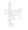
続いて、取付板21、軸受ホルダ23、および軸受部24の、より詳細な固定構造について、説明する。図4は、バーリング部211の付近におけるモータ1の部分横断面図である。図4では、固定構造の理解を容易とするために、バーリング部211、軸受ホルダ23、および第2軸受242が、同一平面内に描かれている。
<3. Mounting plate, bearing holder, and bearing structure fixing structure>
Next, a more detailed fixing structure of the mounting
図4に示すように、取付板21のバーリング部211は、複数のかしめ部215を有する。各かしめ部215は、バーリング部211の他の部位より、径方向外側へ倒されている。また、各かしめ部215の下面は、回路基板22の上面または端縁部に、接触している。これにより、取付板21の内側板状部212と、かしめ部215との間に、回路基板22が挟まれて固定されている。
As shown in FIG. 4, the burring
すなわち、このモータ1では、取付板21自体に設けられたかしめ部215を利用して、取付板21と回路基板22とが、固定されている。このようにすれば、モータ1の部品点数を低減できる。また、ねじ止め等の作業を行う場合より、取付板21と回路基板22とを固定する工程を、短縮できる。また、バーリング部211およびかしめ部215は、取付板21の第1挿入孔210の縁に、設けられている。このため、回路基板22上の電子部品の実装面積が、制限されにくい。
That is, in the
図4に示すように、かしめ部215の径方向内側の面は、バーリング部211の内周面の他の部分より、径方向内側へ突出している。しかしながら、複数のかしめ部215は、複数のホルダ凹部42の径方向外側に、それぞれ配置されている。このため、かしめ部215の径方向内側の面と、ホルダ凹部42との間には、径方向の隙間が存在する。これにより、かしめ部215と軸受ホルダ23との接触が、抑制されている。その結果、軸受ホルダ23の変形およびそれに伴う軸受部24の歪みが、抑制されている。
As shown in FIG. 4, the radially inner surface of the
図5は、かしめ部215の付近におけるモータ1の部分縦断面図である。図5には、かしめ前のバーリング部211と、かしめ時に取付板21を支持する治具60とが、二点鎖線で示されている。図1、図2、および図5に示すように、軸受ホルダ23のフランジ部50には、複数の第1切り欠き部51が設けられている。各第1切り欠き部51は、フランジ部50を軸方向に貫通する。第1切り欠き部51は、ホルダ凹部42の下端部の径方向外側に、位置する。したがって、図5のように、第1切り欠き部51は、かしめ部215の下方に位置する。
FIG. 5 is a partial longitudinal sectional view of the
バーリング部211をかしめるときには、まず、第1切り欠き部51に治具60を挿入する。そして、治具60の上面を、取付板21の内側板状部212の下面に接触させる。これにより、取付板21が支持される。次に、図5中の白抜き矢印のように、バーリング部211に対して、上方から圧力を加える。その結果、バーリング部211が部分的に径方向外側へ倒されて、かしめ部215が形成される。
When caulking the burring
図5に二点鎖線で示したように、本実施形態のバーリング部211は、テーパ面216を有する。テーパ面216は、バーリング部211の上端部と内周面との間に、設けられている。また、テーパ面216は、軸方向および径方向に対して、斜めに広がっている。かしめ部215を形成するときには、テーパ面216に対して荷重が与えられる。これにより、バーリング部211が、容易に径方向外側へ倒される。また、かしめ部215の径方向内側への膨らみも、抑制される。したがって、かしめ部215と軸受ホルダ23との接触が、より抑制される。
As indicated by a two-dot chain line in FIG. 5, the burring
また、図4に示すように、本実施形態の回路基板22には、2つの第2切り欠き部221が設けられている。第2切り欠き部221は、複数のかしめ部215の間において、回路基板22を軸方向に貫通している。取付板21に軸受ホルダ23を圧入するときには、第2切り欠き部221に治具を挿入する。そして、当該治具で取付板21の上面を支持しつつ、軸受ホルダ23を圧入する。
As shown in FIG. 4, the
図6は、ホルダ凸部41の付近におけるモータ1の部分横断面図である。図6では、固定構造の理解を容易とするために、バーリング部211、軸受ホルダ23、および第2軸受242が、同一平面内に描かれている。
FIG. 6 is a partial cross-sectional view of the
図6に示すように、ホルダ凸部41は、さらに径方向外側へ向けて突出した二次凸部411を有する。二次凸部411の径方向外側の面は、ホルダ凸部41の他の部分の径方向外側の面より、径方向外側へ突出している。そして、二次凸部411の径方向外側の面が、バーリング部211の内周面に、接触している。これにより、ホルダ凸部41とバーリング部211との接触部が、狭小化されている。
As shown in FIG. 6, the holder
このように、本実施形態では、ホルダ凸部41のうち、二次凸部411のみが、バーリング部211に接触する。したがって、当該接触によりホルダ凸部41に生じる変位は、二次凸部411の付近に集中する。ホルダ凸部41の変位が二次凸部411の付近に集中すれば、ホルダ凹部42へ伝わる応力が、抑制される。その結果、ホルダ凹部42の変形およびそれに伴う軸受部24の歪みが、抑制される。
Thus, in the present embodiment, only the secondary
二次凸部411は、ホルダ凸部41の周方向の中央に位置していることが、好ましい。そのようにすれば、ホルダ凸部41の変位が,周方向の中央付近に集中する。したがって、ホルダ凹部42へ伝わる応力が、より抑制される。
It is preferable that the secondary
<4.ステータコア、軸受ホルダ、および軸受部の固定構造について>
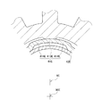
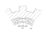
続いて、ステータコア26、軸受ホルダ23、および軸受部24のより詳細な固定構造について、説明する。図7は、コアバック261の付近におけるモータ1の部分横断面図である。図7では、固定構造の理解を容易とするために、軸受ホルダ23とコアバック261との接触部と、軸受ホルダ23と第1軸受241との接触部とが、同一平面内に描かれている。
<4. Stator core, bearing holder, and bearing part fixing structure>
Next, a more detailed fixing structure of the
図7のように、コアバック261の内周面のうち、ホルダ凸部41に対して非接触となる部分の中心角をθ1とする。また、第1軸受241の外周面のうち、ホルダ凹部42に対して接触する部分の中心角をθ2とする。このモータ1では、中心角θ1の大きさが、中心角θ2の大きさ以上となっている。このため、ホルダ凸部41とコアバック261との接触部と、ホルダ凹部42と第1軸受241との接触部とが、径方向に重なっていない。すなわち、ホルダ凸部41とコアバック261との接触部の周方向位置と、ホルダ凹部42と第1軸受241との接触部の周方向位置とが、重なっていない。
As shown in FIG. 7, the central angle of a portion of the inner peripheral surface of the core back 261 that is not in contact with the holder
このような構造においては、ホルダ凸部41とコアバック261との接触部から、ホルダ凹部42と第1軸受241との接触部へ、応力が伝わりにくい。したがって、圧入によって、ホルダ凸部41が径方向内側へ押されたとしても、ホルダ凹部42の内径変形およびそれに伴う軸受部24の歪みは、生じにくい。
In such a structure, stress is not easily transmitted from the contact portion between the holder
特に、本実施形態のステータコア26は、複数の圧入凸部263を有する。各圧入凸部263は、コアバック261の内周面から、径方向内側へ向けて突出している。また、複数の圧入凸部263は、周方向に略等間隔に配列されている。各圧入凸部263の径方向内側の面の周方向の幅は、ホルダ凸部41の径方向外側の面の周方向の幅より、小さい。そして、コアバック261の内周面のうち、圧入凸部263の径方向内側の面のみが、ホルダ凸部41に接触している。
In particular, the
これにより、ステータコア26とホルダ凸部41との接触部の周方向の幅が、制限されている。圧入荷重によるホルダ凸部41の径方向内側への変位は、当該接触部付近に集中する。その結果、ホルダ凹部42へ伝わる応力が、より抑制される。したがって、ホルダ凹部42の変形およびそれに伴う軸受部24の歪みが、より抑制される。
Thereby, the circumferential width of the contact portion between the
また、本実施形態のステータコア26は、複数の圧入凸部263とは別に、位置決め凸部264を有する。位置決め凸部264は、コアバック261の内周面から、径方向内側へ向けて突出している。また、位置決め凸部264は、複数の圧入凸部263より、径方向内側へ突出している。したがって、位置決め凸部264の径方向内側の端部は、ホルダ凸部41の外周面より、径方向内側に位置している。また、位置決め凸部264は、隣り合う一対のホルダ凸部41の間に、配置されている。すなわち、位置決め凸部264は、ホルダ凹部42の径方向外側に設けられた溝に、嵌っている。これにより、ステータコア26に対して、軸受ホルダ23が、周方向に位置決めされている。
In addition, the
位置決め凸部264の周方向の幅は、ホルダ凹部42の周方向の幅より小さい。一方、図7に示すように、ステータコア26の内周面に設けられた他の凸部の周方向の幅は、ホルダ凹部42の周方向の幅より大きい。したがって、ステータコア26の内周面に設けられた複数の凸部のうち、位置決め凸部264のみが、ホルダ凹部42に嵌合可能となっている。このようにすれば、ステータコア26に軸受ホルダ23を圧入するときの位置決め作業が、容易となる。
The circumferential width of the positioning
図8は、第1軸受241の付近におけるモータ1の部分縦断面図である。図8に示すように、本実施形態では、ホルダ凸部41とコアバック261との接触部の軸方向の位置と、ホルダ凹部42と第1軸受241との接触部の軸方向の位置とが、相違している。このため、ホルダ凸部41とコアバック261との接触部から、ホルダ凹部42と第1軸受241との接触部へ、より応力が伝わりにくい。したがって、ホルダ凹部42の内径変形およびそれに伴う軸受部24の歪みが、より抑制される。
FIG. 8 is a partial longitudinal sectional view of the
<5.変形例>
以上、本発明の例示的な実施形態について説明したが、本発明は上記の実施形態に限定されるものではない。
<5. Modification>
As mentioned above, although exemplary embodiment of this invention was described, this invention is not limited to said embodiment.
図9は、一変形例に係るモータ1Aの縦断面図である。図9の例では、第1軸受241Aの上端が、軸受ホルダ23Aの上端よりも、軸方向上側に位置する。このようにすれば、軸受ホルダ23Aの軸方向の長さを長くすることなく、第1軸受241Aと第2軸受242Aとの軸方向の間隔を長くとることができる。したがって、軸受部24Aに支持されるシャフト31Aを、中心軸9Aに沿ってより精度よく配置することができる。
FIG. 9 is a longitudinal sectional view of a
また、図9の例では、ロータホルダ32Aの内側円筒部320Aの下端部が、ステータコア26Aの上面よりも、軸方向下側に位置する。このようにすれば、シャフト31Aおよび内側円筒部320Aの上端部を、天板部321Aの上面よりも上側へ突出させることなく、内側円筒部320Aの軸方向の長さを長くすることができる。したがって、シャフト31Aに対するロータホルダ32Aの固定強度を、より向上させることができる。
In the example of FIG. 9, the lower end portion of the inner
図10は、一変形例に係る軸受ホルダ23Bの縦断面図である。図10の軸受ホルダ23Bは、筒状部40Bの下端部から径方向外側へ広がるフランジ部50Bを有する。このため、筒状部40Bの剛性が、フランジ部50Bによって高められている。ただし、図10の軸受ホルダ23Bは、ホルダ凸部41Bを径方向に貫通する貫通孔412Bを有する。これにより、貫通孔412Bより上側におけるホルダ凸部41Bの可撓性が、向上されている。
FIG. 10 is a longitudinal sectional view of a
貫通孔412Bは、フランジ部50Bより上側に位置している。また、取付板およびステータコアに軸受ホルダ23Bが圧入された状態において、貫通孔412Bは、バーリング部およびコアバックより下側に位置する。このため、バーリング部およびコアバックとの接触部において、ホルダ凸部41Bは、径方向内側に撓みやすい。したがって、ホルダ凹部42Bへ伝わる応力が、より抑制される。
The through
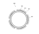
図11は、他の変形例に係る軸受ホルダ23Cの上面図である。図11の軸受ホルダ23Cは、筒状部40Cの下端部から径方向外側へ広がるフランジ部50Cを有する。このため、筒状部40Cの剛性が、フランジ部50Cによって高められている。ただし、図11の軸受ホルダ23Cは、フランジ部50Cを軸方向に貫通する貫通孔52Cを有する。貫通孔52Cの周方向位置と、ホルダ凸部の周方向位置とは、重なっている。これにより、ホルダ凸部41Cの可撓性が、向上されている。
FIG. 11 is a top view of a
ホルダ凸部41Cの可撓性が向上すれば、バーリング部およびコアバックとの接触部において、ホルダ凸部41Cが、径方向内側に撓みやすい。したがって、ホルダ凹部へ伝わる応力が、より抑制される。
If the flexibility of the holder
なお、貫通孔に代えて、フランジ部に切り欠きが設けられていてもよい。ただし、ホルダ凸部の可撓性をより向上させるためには、貫通孔および切り欠きのいずれの場合においても、フランジ部の最内周部が、軸方向に貫通されていることが、好ましい。すなわち、貫通孔または切り欠きの径方向内側のエッジ面が、ホルダ凸部の径方向外側の面の下方に位置していることが、好ましい。 In addition, it replaces with a through-hole and the notch may be provided in the flange part. However, in order to further improve the flexibility of the holder convex portion, it is preferable that the innermost peripheral portion of the flange portion is penetrated in the axial direction in both cases of the through hole and the notch. That is, it is preferable that the edge surface on the radially inner side of the through hole or the notch is positioned below the radially outer surface of the holder convex portion.
図12および図13は、他の変形例に係るモータの部分縦断面図である。図12および図13の例では、軸受部24Dが、第1軸受241Dと、第1軸受241Dより外径の大きい第2軸受242Dとで、構成されている。また、軸受ホルダ23Dは、小径部231Dと、小径部231Dより径の大きい大径部232Dと、を有している。第1軸受241Dは、小径部231Dに保持されている。第2軸受242Dは、大径部232Dに保持されている。このように、上下の軸受の外径を相違させれば、軸受部の上部付近および下部付近のそれぞれに要求される支持力に、対応できる。
12 and 13 are partial longitudinal sectional views of motors according to other modifications. In the example of FIGS. 12 and 13, the bearing
また、図12および図13の軸受ホルダ23Dは、小径部231Dと大径部232Dとの間に、環状の円板部233Dを有している。円板部233Dは、小径部231Dの大径部232D側の端部と、大径部232Dの小径部231D側の端部とを、繋いでいる。特に、図13の例では、取付板21Dの下面と、円板部233Dの上面とが、接触している。このようにすれば、取付板21Dを、軸方向に容易に位置決めできる。
Further, the bearing holder 23D shown in FIGS. 12 and 13 has an
なお、図12および図13の例では、第2軸受242Dおよび大径部232Dが、第1軸受241Dおよび小径部231Dより、下側に位置している。ただし、第2軸受242Dおよび大径部232Dが、第1軸受241Dおよび小径部231Dより、上側に位置していてもよい。
In the example of FIGS. 12 and 13, the
図14は、他の変形例に係るモータの部分横断面図である。図14の例では、ホルダ凸部41Eの周方向中央部413Eの曲率と、ホルダ凸部41Eの周方向両端部414Eの曲率とが、相違する。具体的には、周方向中央部413Eの曲率中心90Eが、中心軸9Eから外れた位置に、配置されている。その結果、ホルダ凸部41Eの周方向中央部413Eの曲率半径が、周方向中央部413Eと中心軸9Eとの距離より、大きくなっている。このようにすれば、ホルダ凸部41Eの周方向中央部413Eの可撓性が、さらに向上する。したがって、ホルダ凹部42Eへ伝わる応力が、より抑制される。
FIG. 14 is a partial cross-sectional view of a motor according to another modification. In the example of FIG. 14, the curvature of the
図15は、他の変形例に係るモータの部分横断面図である。図15の例では、ホルダ凸部41Fの周方向中央部413Fの径方向の厚みが、ホルダ凸部41Fの周方向両端部414Fの径方向の厚みより、薄くなっている。このようにすれば、ホルダ凸部41Fの周方向中央部413Fの可撓性が、さらに向上する。したがって、ホルダ凹部42Fへ伝わる応力が、より抑制される。
FIG. 15 is a partial cross-sectional view of a motor according to another modification. In the example of FIG. 15, the radial thickness of the circumferential
回路基板は、取付板の上面側および下面側の、いずれに配置されていてもよい。例えば、図16のように、取付板21Gの下面側に、回路基板22Gが配置されていてもよい。図16の例では、取付板21Gの第1挿入孔210Gの縁から、下方へ向けて、バーリング部211Gが突出している。そして、回路基板22Gの下面側に、かしめ部215Gが形成されている。
The circuit board may be disposed on either the upper surface side or the lower surface side of the mounting plate. For example, as shown in FIG. 16, the
また、軸受ホルダに設けられる凹凸の数は、上記の実施形態と相違していてもよい。例えば、図17のように、軸受ホルダ23Hが、6つのホルダ凸部41Hと、6つのホルダ凹部42Hとを、有していてもよい。また、図17のように、ホルダ凸部41Hが、二次凸部を有していなくてもよい。ホルダ凸部の径方向外側の面は、その一部分または全体が、外囲部材に接触していればよい。また、ホルダ凹部の径方向内側の面は、その一部分または全体が、軸受部に接触していればよい。
Further, the number of irregularities provided in the bearing holder may be different from that in the above embodiment. For example, as shown in FIG. 17, the
また、ホルダ凸部およびホルダ凹部の各寸法は、本願の各図と相違していてもよい。ただし、ホルダ凸部の可撓性を向上させるためには、ホルダ凸部の周方向の幅を、なるべく広くすることが好ましい。例えば、ホルダ凸部の周方向の幅を、ホルダ凹部の周方向の幅より、大きくすることが好ましい。 Moreover, each dimension of a holder convex part and a holder recessed part may differ from each figure of this application. However, in order to improve the flexibility of the holder convex portion, it is preferable to make the width of the holder convex portion in the circumferential direction as wide as possible. For example, it is preferable to make the circumferential width of the holder convex portion larger than the circumferential width of the holder concave portion.
その他、モータの細部の形状については、本願の各図面と相違していてもよい。また、上記の実施形態や変形例に登場した各要素を、矛盾が生じない範囲で、適宜に組み合わせてもよい。 In addition, about the detailed shape of a motor, you may differ from each drawing of this application. Moreover, you may combine suitably each element which appeared in said embodiment and modification in the range which does not produce inconsistency.
本発明は、モータに利用できる。 The present invention can be used for a motor.
1,1A モータ
9,9A,9E 中心軸
2 静止部
3 回転部
21,21D,21G 取付板
22,22G 回路基板
23,23A,23B,23C,23D,23H 軸受ホルダ
24,24A,24D 軸受部
25 スペーサ
26,26A ステータコア
27 コイル
31,31A シャフト
32,32A ロータホルダ
33 マグネット
40,40B,40C 筒状部
41,41B,41C,41E,41F,41H ホルダ凸部
42,42B,42E,42F,42H ホルダ凹部
43 傾斜部
44 挿入部
50,50B,50C フランジ部
51 第1切り欠き部
52C 貫通孔
210,210G 第1挿入孔
211,211G バーリング部
212 内側板状部
213 段差部
214 外側板状部
215,215G かしめ部
216 テーパ面
221 第2切り欠き部
230 粗面部
231D 小径部
232D 大径部
233D 円板部
241,241A,241D 第1軸受
242,242A,242D 第2軸受
260 第2挿入孔
261 コアバック
262 ティース
263 圧入凸部
264 位置決め凸部
320,320A 内側円筒部
321,321A 天板部
322 外側円筒部
410 接触領域
230 粗面部
411 二次凸部
412B 貫通孔
1,
Claims (10)
前記軸受ホルダの径方向内側に固定された軸受部と、
前記軸受ホルダの径方向外側に固定され、前記中心軸に対して直交する方向に広がる取付板と、
前記取付板の上面または下面に配置された回路基板と、
前記取付板より上方において、前記軸受ホルダの径方向外側に固定されたステータコアと、
前記ステータコアに取り付けられたコイルと、
前記軸受部により回転可能に支持されるシャフトと、
前記シャフトとともに回転するマグネットと、
を有し、
前記取付板は、
前記中心軸と同軸に設けられた円孔を有する板状部と、
前記円孔の縁から軸方向に突出するバーリング部と、
を有し、
前記軸受ホルダの外周面は、前記バーリング部に接触する接触領域を有し、
前記軸受ホルダの外周面または前記取付板の表面は、前記接触領域の付近に、前記接触領域の広さよりも細かいピッチで凹凸を繰り返す粗面部を有するモータ。 A bearing holder extending in a substantially cylindrical shape in the axial direction around a central axis extending vertically;
A bearing portion fixed radially inward of the bearing holder;
A mounting plate that is fixed radially outward of the bearing holder and extends in a direction perpendicular to the central axis;
A circuit board disposed on the upper or lower surface of the mounting plate;
Above the mounting plate, a stator core fixed outside in the radial direction of the bearing holder;
A coil attached to the stator core;
A shaft rotatably supported by the bearing portion;
A magnet that rotates with the shaft;
Have
The mounting plate is
A plate-like portion having a circular hole provided coaxially with the central axis;
A burring portion protruding in an axial direction from an edge of the circular hole;
Have
The outer peripheral surface of the bearing holder has a contact area that contacts the burring portion,
The motor which has the rough surface part in which the outer peripheral surface of the said bearing holder or the surface of the said mounting plate repeats an unevenness | corrugation by the finer pitch than the width of the said contact area in the vicinity of the said contact area.
前記軸受ホルダの外周面が、前記粗面部を含むモータ。 The motor according to claim 1,
A motor in which an outer peripheral surface of the bearing holder includes the rough surface portion.
前記軸受ホルダの外周面のうち、前記粗面部の面粗度が、前記取付板の表面の面粗度よりも、大きいモータ。 The motor according to claim 2,
The motor whose surface roughness of the rough surface portion is larger than the surface roughness of the surface of the mounting plate in the outer peripheral surface of the bearing holder.
前記軸受ホルダは、
径方向外側の面が少なくとも部分的に前記バーリング部に接触する複数のホルダ凸部と、
前記ホルダ凸部より径方向内側に位置し、径方向内側の面が少なくとも部分的に前記軸受部に接触する複数のホルダ凹部と、
を有し、
少なくとも前記ホルダ凸部の径方向外側の面が、前記粗面部を含むモータ。 The motor according to claim 3, wherein
The bearing holder is
A plurality of holder protrusions whose radially outer surfaces at least partially contact the burring portion;
A plurality of holder recesses that are located radially inward from the holder protrusion, and at least partially in contact with the bearing portion, the radially inner surface;
Have
A motor in which at least a radially outer surface of the holder convex portion includes the rough surface portion.
前記ホルダ凸部の径方向外側の面および前記ホルダ凹部の径方向外側の面が、前記粗面部を含み、
前記ホルダ凹部の前記粗面部の面粗度と、前記ホルダ凸部の前記接触領域よりも軸方向上側または軸方向下側に位置する前記粗面部の面粗度とが、略同一であるモータ。 The motor according to claim 4,
The radially outer surface of the holder convex portion and the radially outer surface of the holder concave portion include the rough surface portion,
The motor in which the surface roughness of the rough surface portion of the holder recess and the surface roughness of the rough surface portion positioned on the upper side in the axial direction or the lower side in the axial direction than the contact area of the holder convex portion are substantially the same.
前記接触領域よりも軸方向上側に位置する前記粗面部の面粗度と、前記接触領域よりも軸方向下側に位置する前記粗面部の面粗度とが、互いに異なるモータ。 In the motor according to any one of claims 2 to 5,
A motor in which the surface roughness of the rough surface portion located on the upper side in the axial direction from the contact region and the surface roughness of the rough surface portion located on the lower side in the axial direction from the contact region are different from each other.
前記粗面部の少なくとも一部分の面粗度は、Ra≧60μmであるモータ。 The motor according to any one of claims 1 to 6, wherein
The surface roughness of at least a part of the rough surface portion is a motor where Ra ≧ 60 μm.
前記軸受部は、
第1軸受と、
前記第1軸受よりも軸方向下側に位置する第2軸受と、
を有し、
前記第1軸受の上端は、前記軸受ホルダの上端よりも、軸方向上側に位置するモータ。 In the motor according to any one of claims 1 to 7,
The bearing portion is
A first bearing;
A second bearing located axially below the first bearing;
Have
A motor in which an upper end of the first bearing is positioned axially above an upper end of the bearing holder.
前記シャフトに固定されるとともに前記マグネットを保持するロータホルダをさらに有し、
前記ロータホルダは、前記シャフトの外周面に固定される内側円筒部を有し、
前記内側円筒部の下端部は、前記ステータコアの上面よりも、軸方向下側に位置するモータ。 In the motor according to any one of claims 1 to 8,
A rotor holder fixed to the shaft and holding the magnet;
The rotor holder has an inner cylindrical portion fixed to the outer peripheral surface of the shaft,
The lower end portion of the inner cylindrical portion is a motor located on the lower side in the axial direction than the upper surface of the stator core.
前記粗面部は、ブラスト加工により形成されるモータ。 In the motor according to any one of claims 1 to 9,
The rough surface portion is a motor formed by blasting.
Priority Applications (2)
| Application Number | Priority Date | Filing Date | Title |
|---|---|---|---|
| JP2014264195A JP2016127620A (en) | 2014-12-26 | 2014-12-26 | motor |
| CN201520986784.XU CN205231904U (en) | 2014-12-26 | 2015-12-02 | Motor |
Applications Claiming Priority (1)
| Application Number | Priority Date | Filing Date | Title |
|---|---|---|---|
| JP2014264195A JP2016127620A (en) | 2014-12-26 | 2014-12-26 | motor |
Publications (1)
| Publication Number | Publication Date |
|---|---|
| JP2016127620A true JP2016127620A (en) | 2016-07-11 |
Family
ID=55906946
Family Applications (1)
| Application Number | Title | Priority Date | Filing Date |
|---|---|---|---|
| JP2014264195A Pending JP2016127620A (en) | 2014-12-26 | 2014-12-26 | motor |
Country Status (2)
| Country | Link |
|---|---|
| JP (1) | JP2016127620A (en) |
| CN (1) | CN205231904U (en) |
Cited By (1)
| Publication number | Priority date | Publication date | Assignee | Title |
|---|---|---|---|---|
| CN108233586A (en) * | 2016-12-22 | 2018-06-29 | 日本电产(东莞)有限公司 | Motor |
Families Citing this family (4)
| Publication number | Priority date | Publication date | Assignee | Title |
|---|---|---|---|---|
| CN105827033B (en) * | 2016-05-23 | 2018-10-16 | 珠海格力节能环保制冷技术研究中心有限公司 | A kind of electric machine support and use its motor |
| JP2018201302A (en) * | 2017-05-29 | 2018-12-20 | 日本電産株式会社 | motor |
| CN111146884A (en) * | 2018-11-06 | 2020-05-12 | 日本电产株式会社 | Motor and vehicle |
| CN110365136A (en) * | 2019-08-26 | 2019-10-22 | 珠海凯邦电机制造有限公司 | The supporting structure and motor of motor |
Citations (4)
| Publication number | Priority date | Publication date | Assignee | Title |
|---|---|---|---|---|
| JPH08210370A (en) * | 1995-01-31 | 1996-08-20 | Ntn Corp | Bearing fitting structure |
| JP2008289323A (en) * | 2007-05-21 | 2008-11-27 | Nippon Densan Corp | Motor |
| JP2012125129A (en) * | 2010-11-15 | 2012-06-28 | Nippon Densan Corp | Motor |
| JP2013150484A (en) * | 2012-01-20 | 2013-08-01 | Nippon Densan Corp | Motor |
-
2014
- 2014-12-26 JP JP2014264195A patent/JP2016127620A/en active Pending
-
2015
- 2015-12-02 CN CN201520986784.XU patent/CN205231904U/en not_active Expired - Fee Related
Patent Citations (4)
| Publication number | Priority date | Publication date | Assignee | Title |
|---|---|---|---|---|
| JPH08210370A (en) * | 1995-01-31 | 1996-08-20 | Ntn Corp | Bearing fitting structure |
| JP2008289323A (en) * | 2007-05-21 | 2008-11-27 | Nippon Densan Corp | Motor |
| JP2012125129A (en) * | 2010-11-15 | 2012-06-28 | Nippon Densan Corp | Motor |
| JP2013150484A (en) * | 2012-01-20 | 2013-08-01 | Nippon Densan Corp | Motor |
Cited By (1)
| Publication number | Priority date | Publication date | Assignee | Title |
|---|---|---|---|---|
| CN108233586A (en) * | 2016-12-22 | 2018-06-29 | 日本电产(东莞)有限公司 | Motor |
Also Published As
| Publication number | Publication date |
|---|---|
| CN205231904U (en) | 2016-05-11 |
Similar Documents
| Publication | Publication Date | Title |
|---|---|---|
| JP5765671B2 (en) | motor | |
| US10084361B2 (en) | Motor | |
| JP5804269B2 (en) | motor | |
| JP2016127620A (en) | motor | |
| JP6429115B2 (en) | motor | |
| JP6260291B2 (en) | motor | |
| US10447100B2 (en) | Motor | |
| JP2018201303A (en) | motor | |
| US11005328B2 (en) | Motor | |
| CN204258508U (en) | Motor | |
| US11233433B2 (en) | Rotor and motor | |
| JP2016129473A (en) | motor | |
| JP7123261B2 (en) | Rotor for rotary electric machine and manufacturing method thereof | |
| JP5487020B2 (en) | Rotating electric machine | |
| CN108933496B (en) | Motor | |
| JP5317228B2 (en) | Rotating electric machine | |
| JP2018107839A (en) | Stator core for rotary electric machine, stator and rotary electric machine | |
| JPWO2019111879A1 (en) | Gear system with motor | |
| JP5903545B2 (en) | Core material, stator core, and motor including the stator core | |
| JP2014236563A (en) | Rotor body | |
| JP2013243865A (en) | Press-fit fixing structure | |
| JP2016167959A (en) | Stator and motor | |
| JP2016025669A (en) | Rotor | |
| JP2015156774A (en) | motor |
Legal Events
| Date | Code | Title | Description |
|---|---|---|---|
| A621 | Written request for application examination |
Free format text: JAPANESE INTERMEDIATE CODE: A621 Effective date: 20171121 |
|
| A977 | Report on retrieval |
Free format text: JAPANESE INTERMEDIATE CODE: A971007 Effective date: 20180914 |
|
| A131 | Notification of reasons for refusal |
Free format text: JAPANESE INTERMEDIATE CODE: A131 Effective date: 20180925 |
|
| A521 | Request for written amendment filed |
Free format text: JAPANESE INTERMEDIATE CODE: A523 Effective date: 20181119 |
|
| A02 | Decision of refusal |
Free format text: JAPANESE INTERMEDIATE CODE: A02 Effective date: 20190205 |