JP2016127419A - Image correction device, image correction method, and program - Google Patents
Image correction device, image correction method, and program Download PDFInfo
- Publication number
- JP2016127419A JP2016127419A JP2014266669A JP2014266669A JP2016127419A JP 2016127419 A JP2016127419 A JP 2016127419A JP 2014266669 A JP2014266669 A JP 2014266669A JP 2014266669 A JP2014266669 A JP 2014266669A JP 2016127419 A JP2016127419 A JP 2016127419A
- Authority
- JP
- Japan
- Prior art keywords
- image
- unit
- imaging
- subject
- correction
- Prior art date
- Legal status (The legal status is an assumption and is not a legal conclusion. Google has not performed a legal analysis and makes no representation as to the accuracy of the status listed.)
- Pending
Links
Images


Abstract
Description
本発明は、画像補正装置、画像補正方法及びプログラムに関する。 The present invention relates to an image correction apparatus, an image correction method, and a program.
従来より、従来、撮像された画像中の人物の顔を補正するか否かを正面の顔の回転角度に応じて制御する技術がある(特許文献1参照)。 Conventionally, there is a technique for controlling whether or not to correct a human face in a captured image according to the rotation angle of the front face (see Patent Document 1).
しかしながら、上記特許文献1に記載の技術では、顔の補正をする場合に正面の顔の回転角度のみを補正の可否の考慮に入れており、撮影方法については何ら考慮されていなかった。 However, in the technique described in Patent Document 1, only the rotation angle of the front face is taken into consideration whether correction is possible when correcting the face, and no consideration is given to the photographing method.
本発明は、上記のような問題に鑑みてなされたものであり、撮影方法を考慮した好適な被写体を含む画像を得ることを目的とする。 The present invention has been made in view of the above problems, and an object of the present invention is to obtain an image including a suitable subject in consideration of a photographing method.
上記目的を達成するため、本発明の一態様の画像補正装置は、
画像を取得する第1の取得手段と、
前記第1の取得手段により取得された画像中の被写体の形状を補正する補正手段と、
前記被写体と撮像手段との撮像時の位置関係の情報を取得する第2の取得手段と、
前記第2の取得手段により取得された位置関係の情報に基づいて、前記補正手段による補正処理の強度を制御する制御手段と、
を備えたことを特徴とする。
In order to achieve the above object, an image correction apparatus according to an aspect of the present invention includes:
First acquisition means for acquiring an image;
Correction means for correcting the shape of the subject in the image acquired by the first acquisition means;
Second acquisition means for acquiring positional relationship information at the time of imaging between the subject and the imaging means;
Control means for controlling the intensity of the correction processing by the correction means based on the positional relationship information acquired by the second acquisition means;
It is provided with.
本発明によれば、撮影方法を考慮した好適な被写体を含む画像を得ることができる。 According to the present invention, it is possible to obtain an image including a suitable subject in consideration of the photographing method.
以下、本発明の実施形態について、図面を用いて説明する。 Hereinafter, embodiments of the present invention will be described with reference to the drawings.
図1は、本発明の一実施形態に係る撮像装置のハードウェアの構成を示すブロック図である。
撮像装置1は、例えばデジタルカメラとして構成される。
FIG. 1 is a block diagram showing a hardware configuration of an imaging apparatus according to an embodiment of the present invention.
The imaging device 1 is configured as a digital camera, for example.
撮像装置1は、CPU(Central Processing Unit)11と、ROM(Read Only Memory)12と、RAM(Random Access Memory)13と、バス14と、入出力インターフェース15と、センサ部16と、撮像部17と、入力部18と、出力部19と、記憶部20と、通信部21と、ドライブ22と、を備えている。
The imaging device 1 includes a CPU (Central Processing Unit) 11, a ROM (Read Only Memory) 12, a RAM (Random Access Memory) 13, a
CPU11は、ROM12に記録されているプログラム、又は、記憶部20からRAM13にロードされたプログラムに従って各種の処理を実行する。
The
RAM13には、CPU11が各種の処理を実行する上において必要なデータ等も適宜記憶される。
The
CPU11、ROM12及びRAM13は、バス14を介して相互に接続されている。このバス14にはまた、入出力インターフェース15も接続されている。入出力インターフェース15には、センサ部16、撮像部17、入力部18、出力部19、記憶部20、通信部21及びドライブ22が接続されている。
The
センサ部16は、加速度センサを用いて重力方向との角度によって、撮像装置1の姿勢を検出可能に構成される。撮影時の撮像装置1の姿勢の検出によって、被写体と撮像部17との撮像時の位置関係を示す撮影方向を把握することができるようになる。
The
撮像部17は、図示はしないが、光学レンズ部と、イメージセンサと、を備えている。
Although not shown, the
光学レンズ部は、被写体を撮影するために、光を集光するレンズ、例えばフォーカスレンズやズームレンズ等で構成される。
フォーカスレンズは、イメージセンサの受光面に被写体像を結像させるレンズである。ズームレンズは、焦点距離を一定の範囲で自在に変化させるレンズである。
光学レンズ部にはまた、必要に応じて、焦点、露出、ホワイトバランス等の設定パラメータを調整する周辺回路が設けられる。
The optical lens unit is configured by a lens that collects light, for example, a focus lens or a zoom lens, in order to photograph a subject.
The focus lens is a lens that forms a subject image on the light receiving surface of the image sensor. The zoom lens is a lens that freely changes the focal length within a certain range.
The optical lens unit is also provided with a peripheral circuit for adjusting setting parameters such as focus, exposure, and white balance as necessary.
イメージセンサは、光電変換素子や、AFE(Analog Front End)等から構成される。
光電変換素子は、例えばCMOS(Complementary Metal Oxide Semiconductor)型の光電変換素子等から構成される。光電変換素子には、光学レンズ部から被写体像が入射される。そこで、光電変換素子は、被写体像を光電変換(撮像)して画像信号を一定時間蓄積し、蓄積した画像信号をアナログ信号としてAFEに順次供給する。
AFEは、このアナログの画像信号に対して、A/D(Analog/Digital)変換処理等の各種信号処理を実行する。各種信号処理によって、ディジタル信号が生成され、撮像部17の出力信号として出力される。
このような撮像部17の出力信号を、以下、「撮像画像のデータ」と呼ぶ。撮像画像のデータは、CPU11や図示しない画像処理部等に適宜供給される。
The image sensor includes a photoelectric conversion element, AFE (Analog Front End), and the like.
The photoelectric conversion element is composed of, for example, a CMOS (Complementary Metal Oxide Semiconductor) type photoelectric conversion element or the like. A subject image is incident on the photoelectric conversion element from the optical lens unit. Therefore, the photoelectric conversion element photoelectrically converts (captures) the subject image, accumulates the image signal for a predetermined time, and sequentially supplies the accumulated image signal as an analog signal to the AFE.
The AFE performs various signal processing such as A / D (Analog / Digital) conversion processing on the analog image signal. A digital signal is generated by various signal processing and output as an output signal of the
Such an output signal of the
入力部18は、各種釦等で構成され、ユーザの指示操作に応じて各種情報を入力する。
出力部19は、ディスプレイやスピーカ等で構成され、画像や音声を出力する。
記憶部20は、ハードディスク或いはDRAM(Dynamic Random Access Memory)等で構成され、各種画像のデータを記憶する。
通信部21は、インターネットを含むネットワークを介して他の装置(図示せず)との間で行う通信を制御する。
The
The
The
The
ドライブ22には、磁気ディスク、光ディスク、光磁気ディスク、或いは半導体メモリ等よりなる、リムーバブルメディア31が適宜装着される。ドライブ22によってリムーバブルメディア31から読み出されたプログラムは、必要に応じて記憶部20にインストールされる。また、リムーバブルメディア31は、記憶部20に記憶されている画像のデータ等の各種データも、記憶部20と同様に記憶することができる。
A
このように構成される撮像装置1では、取得した撮像画像に対して、人の顔の撮影方向に応じて、被写体の形状である顔を細く見せる補正(以下、「細顔補正」という。)の強度を変更する機能を有する。 In the imaging apparatus 1 configured as described above, the acquired captured image is corrected so as to make the face that is the shape of the subject look narrow according to the shooting direction of the human face (hereinafter referred to as “thin face correction”). It has a function to change the strength.
図2は、本実施形態における細顔補正を説明するための模式図である。
人の顔は、図2に示すように、顔を上方向から撮影した場合には、頭の部分(髪等の部分)と撮像装置1の距離が近くなり、撮像装置1と顎の距離が遠くなること等の理由から、頭の部分が大きくなり、顎が細く写る。
これに対して、顔を下方向から撮影した場合には、頭の部分と撮像装置1の距離が遠くなり、撮像装置1と顎の距離が近くなる等の理由から、頭の部分が小さくなり、顎が太く写る。
このため、細顔補正では、上方向から撮影をし、顎が細く見えるような場合には、画像変形処理を施すと顔のバランスが崩れるために、画像変形処理を行わないか/標準の強度よりも弱めの強度で画像変形処理を施すようにする。
これに対して、下方向から撮影をし、顎が太く見えるような場合には、逆に、標準よりも強めの強度で画像変形処理を施すようにする。
これにより、顔のバランスを崩すことなく、細顔に見える補正を施すことができる。
FIG. 2 is a schematic diagram for explaining the fine face correction in the present embodiment.
As shown in FIG. 2, when a human face is photographed from above, the distance between the head portion (hair portion or the like) and the imaging device 1 is close, and the distance between the imaging device 1 and the jaw is small. For reasons such as being far away, the head becomes larger and the chin becomes thinner.
On the other hand, when the face is photographed from below, the head portion becomes smaller because the distance between the head portion and the imaging device 1 becomes longer and the distance between the imaging device 1 and the jaw becomes shorter. , The jaws appear thick.
For this reason, in the case of fine face correction, if the image is taken from above and the chin appears to be thin, the balance of the face is lost when the image deformation process is performed. The image deformation process is performed with a weaker intensity.
On the other hand, when the image is taken from below and the chin appears thick, the image deformation process is performed with an intensity stronger than the standard.
As a result, it is possible to perform correction that looks like a narrow face without breaking the balance of the face.
ここで、本実施形態における細顔補正の手法について説明する。
図3は、本実施形態における細顔補正の手法を説明するための模式図である。
Here, the method of fine face correction in the present embodiment will be described.
FIG. 3 is a schematic diagram for explaining a fine face correction method according to this embodiment.
本実施形態の細顔補正では、まず、補正の対象となる画像(以下、「元画像」という。)P1において、顎を含む周囲の領域(以下、「トリミング領域」という。)R1を元画像からトリミングする。本実施形態においてトリミング領域R1は、鼻の下の部分を中心とした顎を含む領域とする。具体的には、トリミング領域R1は、例えば、顔枠R0の中心から顎方向へ25%ズラした位置(鼻の下の部分)で、顔枠R0の1.65倍のサイズとする。 In the fine face correction of the present embodiment, first, in an image (hereinafter referred to as “original image”) P1 to be corrected, a surrounding area (hereinafter referred to as “trimming area”) R1 including the jaw is the original image. Trim from. In the present embodiment, the trimming region R1 is a region including the jaw centered on the lower part of the nose. Specifically, the trimming region R1 is, for example, a position that is 25% shifted from the center of the face frame R0 in the jaw direction (a portion under the nose) and is 1.65 times the size of the face frame R0.
次に、細顔補正では、トリミングの結果、生成される画像(以下、「トリミング画像」という。)P2に対して、上述した撮影方向に対応した強度で細顔補正を行う。本実施形態において細顔補正は、トリミング画像P2の中心(鼻の下の部分)に向かって放射状(本実施形態においては、中心から楕円形)に、中心方向に引っ張るような画像変形処理を行うように構成する。このように鼻の下の部分に向かって放射状(本実施形態においては、中心から楕円形)に中心方向に引っ張るような画像変形処理を行うことで、顔のバランスを崩さずに顎を細くする補正をすることができる。トリミング画像P2に対して細顔補正を行うことで、処理画像P3が生成される。 Next, in the fine face correction, fine face correction is performed on the image P2 generated as a result of the trimming (hereinafter referred to as “trimmed image”) with an intensity corresponding to the above-described shooting direction. In the present embodiment, the fine face correction performs an image deformation process that pulls radially toward the center (in the present embodiment, an ellipse from the center) toward the center (the lower part of the nose) of the trimmed image P2. Configure as follows. In this way, by performing image deformation processing that pulls radially toward the lower part of the nose (in this embodiment, from the center to an ellipse) in the center direction, the chin is narrowed without breaking the balance of the face. Corrections can be made. By performing fine face correction on the trimmed image P2, a processed image P3 is generated.
その後、細顔補正では、画像処理を施したトリミング画像P2である処理画像P3を元画像P1のトリミング領域に対応する領域R2に貼り付けて合成することで細顔補正を施した画像(以下、「細顔補正画像」という。)P4を生成する。 Thereafter, in the fine face correction, the processed image P3, which is the trimmed image P2 subjected to the image processing, is pasted to the region R2 corresponding to the trimming region of the original image P1 and synthesized, and then the image subjected to the fine face correction (hereinafter, referred to as the face image correction) This is referred to as “fine face corrected image”.) P4 is generated.
図4は、このような撮像装置1の機能的構成のうち、細顔撮影処理を実行するための機能的構成を示す機能ブロック図である。
細顔撮影処理とは、元画像に対して、撮影方向に応じた強度で細顔補正を施して細顔補正画像を生成するまでの一連の処理をいう。
FIG. 4 is a functional block diagram showing a functional configuration for executing the fine face photographing process among the functional configurations of the imaging apparatus 1 as described above.
The small face photographing process refers to a series of processes from the original image being subjected to the fine face correction with the intensity according to the photographing direction to generate the fine face corrected image.
細顔撮影処理を実行する場合には、図4に示すように、CPU11において、角度情報取得部51と、撮像制御部52と、顔検出部53と、画像変形処理部54と、トリミング処理部55と、細顔補正画像生成部56と、が機能する。
When executing the narrow face photographing process, as shown in FIG. 4, in the
また、記憶部20の一領域には、角度情報記憶部71と、画像記憶部72と、が設定される。
An angle
角度情報記憶部71には、センサ部16から取得したセンサ部16でのセンシングの時刻を含むセンサ値からの角度情報が記憶される。「角度情報」は、撮像装置1の姿勢がわかる情報であり、撮像装置1の姿勢と共に、当該姿勢時の撮像装置1の動作状態の情報も付加される。したがって、「角度情報」からは、撮影時の撮像装置1の姿勢、即ち、撮影時の撮像装置1の撮影方向(上下/正面方向)がわかる。
The angle
画像記憶部72には、撮像部17から取得した撮像画像や生成した細顔補正画像のデータが記憶される。
The
角度情報取得部51は、センサ部16からのセンサ値に基づいて、角度情報を取得する。角度情報取得部51は、取得した角度情報を角度情報記憶部71に記憶させる。
また、角度情報取得部51は、角度情報記憶部71から元画像の撮像時の角度情報を取得する。なお、本実施形態においては、角度情報取得部51は、元画像の撮影時刻と対応したセンサ部16でのセンシングの時刻の角度情報を撮像時の角度情報として取得する。
The angle
Further, the angle
撮像制御部52は、撮像処理を実行するように撮像部17を制御する。撮像処理の結果、撮像部17から撮像画像が出力される。
The
顔検出部53は、撮像部17から出力された撮像画像である元画像を取得して解析し顔を検出する。顔検出は、既存の顔検出技術を用いる。
The
画像変形処理部54は、角度情報取得部51によって取得された撮影時の撮像装置1の角度に応じた画像変形処理の強度を決定する。具体的には、トリミング処理部55は、図2に示すように、撮影時の撮像装置1の角度が下向きの場合には、顔を上から撮影することになるため、撮影される顔には細顔効果が発揮され易くことから、画像変形処理の強度を無し又は弱くし、撮影時の撮像装置1の角度が正面からの場合には、画像変形処理の強度を標準のものとし、撮影時の撮像装置1の角度が上向きの場合には、顔を下から撮影することになるため、撮影される顔には上方向への撮影の場合とは逆に顔全体が太く写る効果が発揮され易くなることから、画像変形処理の強度を標準よりも強くする。
The image
また、画像変形処理部54は、トリミング画像のうち、顔の顎付近の領域に対して、設定された強度で、画像変形処理を実行する。具体的には、画像変形処理部54は、図3に示すように、設定された歪みの補正強度(上方向[無/弱]・正面[標準]・下方向[強])で、トリミング画像P2の中心(鼻の下の部分)に向かって放射状(本実施形態においては、中心から楕円形)に、中心方向に引っ張るような画像変形処理を行う。
画像変形処理の結果、トリミング画像に対して細顔補正がなされた画像が生成される。
In addition, the image
As a result of the image transformation process, an image in which the fine face correction is performed on the trimmed image is generated.
トリミング処理部55は、元画像のうち、顔の顎付近をトリミング領域として設定する。具体的には、トリミング処理部55は、図3に示すように、元画像P1において、鼻の下の部分を中心とした顎を含む周囲の領域をトリミング領域R1として設定する。詳細には、例えば、トリミング領域R1は、顔枠R0の中心から顎方向へ25%ズラした位置(鼻の下の部分)で、顔枠R0の1.65倍のサイズとする。
The trimming
また、トリミング処理部55は、元画像のうち、設定したトリミング領域をトリミングするトリミング処理を実行する。具体的には、トリミング処理部55は、図3に示すように、設定したトリミング領域R1を元画像P1からトリミングする。
元画像のトリミング領域で構成されるトリミング画像が生成される。
In addition, the trimming
A trimmed image composed of the trimmed area of the original image is generated.
細顔補正画像生成部56は、処理画像を元画像のトリミング領域に対応する領域に貼り付けて細顔補正画像を生成する。具体的には、細顔補正画像生成部56は、図3に示すように、処理画像P3を元画像P1のトリミング領域に対応する領域R2に貼り付けて合成することで細顔補正画像P4を生成する。
また、細顔補正画像生成部56は、細顔補正画像を画像記憶部72に記憶させる。
The fine face corrected
Further, the fine face correction
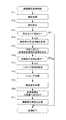
図5は、図4の機能的構成を有する図1の撮像装置1が実行する細顔撮影処理の流れを説明するフローチャートである。
細顔撮影処理は、ユーザによる入力部18への細顔撮影処理開始の操作により開始される。細顔撮影処理開始により、角度情報取得部51は、センサ部16からのセンサ値を角度情報として逐次取得して、角度情報記憶部71に記憶させる。
FIG. 5 is a flowchart for explaining the flow of the narrow face photographing process executed by the imaging apparatus 1 of FIG. 1 having the functional configuration of FIG.
The small face photographing process is started by an operation of starting the thin face photographing process on the
ステップS11において、撮像制御部52は、撮像処理を実行するように撮像部17を制御する。撮像処理の結果、撮像部17から撮像画像が出力される。
In step S11, the
ステップS12において、顔検出部53は、撮像部17から出力された撮像画像である元画像を取得して解析し顔を検出する。
In step S <b> 12, the
ステップS13において、顔検出部53は、撮像画像内に顔があったか否かを判定する。
顔があった場合には、ステップS13においてYESと判定されて、処理はステップS14に進む。
顔がなかった場合には、ステップS13においてNOと判定されて、細顔撮影処理は終了する。細顔撮影処理の終了に際して、撮像画像は画像記憶部72に記憶される。
In step S <b> 13, the
If there is a face, YES is determined in step S13, and the process proceeds to step S14.
If there is no face, it is determined as NO in step S13, and the narrow face photographing process ends. At the end of the fine face photographing process, the captured image is stored in the
ステップS14において、角度情報取得部51は、センサ部16から取得した撮影時の撮像装置1の角度の情報を角度情報記憶部71から取得する。
In step S <b> 14, the angle
ステップS15において、画像変形処理部54は、角度情報取得部51によって取得された撮影時の撮像装置1の角度(上/下/正面方向)に応じた画像変形処理の強度を決定する。具体的には、トリミング処理部55は、撮影時の撮像装置1の角度が下向きの場合には、顔を上から撮影することになるため、既に細顔効果が発揮され易くなることから、画像変形処理を無し又は強度を弱くし、撮影時の撮像装置1の角度が正面からの場合には、画像変形処理の強度を通常のものとし、撮影時の撮像装置1の角度が上向きの場合には、顔を下から撮影することになるため、細顔とは逆の効果が発揮されることから、画像変形処理の強度を通常よりも強くする。
In step S <b> 15, the image
ステップS16において、画像変形処理部54は、例えば、ユーザによる入力部18への画像変形処理実行操作等の有無から本実施形態の画像変形処理を実行するか否かを判定する。
画像変形処理を実行する場合には、ステップS16においてYESと判定されて、処理はステップS17に進む。
画像変形処理を実行しない場合には、ステップS16においてNOと判定されて、細顔撮影処理は終了する。細顔撮影処理の終了に際して、撮像画像は画像記憶部72に記憶される。
In step S <b> 16, the image
When executing the image transformation process, it is determined as YES in Step S16, and the process proceeds to Step S17.
If the image transformation process is not executed, NO is determined in step S16, and the narrow face photographing process ends. At the end of the fine face photographing process, the captured image is stored in the
ステップS17において、トリミング処理部55は、元画像のうち、顔の顎付近をトリミング領域として設定する。具体的には、トリミング処理部55は、図3に示すように、元画像P1において、鼻の下の部分を中心とした顎を含む周囲の領域をトリミング領域R1として設定する。
In step S17, the trimming
ステップS18において、トリミング処理部55は、元画像のうち、設定したトリミング領域をトリミングするトリミング処理を実行する。具体的には、トリミング処理部55は、図3に示すように、設定したトリミング領域R1を元画像P1からトリミングする。
トリミング処理の結果、元画像のトリミング領域で構成されるトリミング画像が生成される。
In step S <b> 18, the trimming
As a result of the trimming process, a trimmed image composed of the trimming area of the original image is generated.
ステップS19において、画像変形処理部54は、トリミング画像のうち、顔の顎付近の領域に対して、設定された歪みの補正強度で、画像処理を実行する。具体的には、画像変形処理部54は、図3に示すように、設定された歪みの補正強度(上方向[無/弱]・正面[標準]・下方向[強])で、トリミング画像P2の中心(鼻の下の部分)に向かって放射状に引っ張るような画像変形処理を行う。
画像変形処理の結果、トリミング画像に対して細顔補正のための画像処理がなされた画像が生成される。
In step S <b> 19, the image
As a result of the image transformation process, an image is generated in which image processing for fine face correction is performed on the trimmed image.
ステップS20において、細顔補正画像生成部56は、処理画像を元画像のトリミング領域に対応する領域に貼り付けて細顔補正画像を生成する。具体的には、細顔補正画像生成部56は、図3に示すように、処理画像P3を元画像P1のトリミング領域に対応する領域R2に貼り付けて合成することで細顔補正画像P4を生成する。
In step S <b> 20, the small face correction
ステップS21において、細顔補正画像生成部56は、細顔補正画像を画像記憶部72に記憶させる。
その後、細顔撮影処理は終了する。
In step S <b> 21, the small face correction
Thereafter, the narrow face photographing process ends.
<変形例>
上述した実施形態においては、センサ部16による角度情報を用いて撮影方向を特定するように構成したが、本例では、画像解析を用いて撮影方向を特定するように構成する。
具体的には、画像解析として、予め登録した撮影方向別の顔画像と、撮影画像とを画像マッチングして撮影方向を特定することができる。また、画像解析として、頭部に対する顎の比率や、正面での頭部や顎に対しての比率で撮影方向を特定することができる。また、画像解析として、目における白黒部分の位置/比率や予め登録した視線の画像とのマッチングにより視線方向を特定して、撮影方向を特定することができる。
この場合、画像解析を用いることで、顔検出部53による顔検出の情報を、顔の有無の判断以外にも用いることができ、顔検出処理をさらに有効に利用することができる。
上述したようにセンサ部16による角度情報や画像処理のみを用いて撮影方向を特定するように構成したが、撮影方向の特定精度を高めるために、手法の異なる画像解析を複数組み合わせて、撮影方向を特定するように構成してもよい。
また、撮影方向の特定精度をさらに高めるために、画像解析と、センサ部16からの角度情報の異なる観点の手法を複合的に用いて、撮影方向を特定するように構成してもよい。
<Modification>
In the above-described embodiment, the photographing direction is specified by using the angle information from the
Specifically, as the image analysis, it is possible to specify the shooting direction by performing image matching between the face image for each shooting direction registered in advance and the shot image. Further, as the image analysis, the photographing direction can be specified by the ratio of the chin to the head or the ratio of the front to the head and chin. In addition, as the image analysis, it is possible to specify the shooting direction by specifying the line-of-sight direction by matching with the position / ratio of the black-and-white portion of the eye and the image of the line of sight registered in advance.
In this case, by using image analysis, face detection information by the
As described above, the imaging direction is specified using only the angle information and image processing performed by the
Further, in order to further increase the accuracy of specifying the shooting direction, the shooting direction may be specified by using a combination of image analysis and methods from different viewpoints of angle information from the
したがって、撮像装置1では、撮影位置を考慮し、撮影位置に応じて細顔補正処理の補正強度を調整することでより効果的な画像を得ることができる。 Therefore, the imaging apparatus 1 can obtain a more effective image by considering the shooting position and adjusting the correction strength of the fine face correction process according to the shooting position.
以上のように構成される撮像装置1は、顔検出部53と、画像変形処理部54と、角度情報取得部51とを備える。
顔検出部53は、撮像画像を取得する。
画像変形処理部54は、顔検出部53により取得された画像中の被写体の形状を補正する。
角度情報取得部51は、被写体と撮像部17との撮像時の位置関係の情報を取得する。
画像変形処理部54は、角度情報取得部51により取得された位置関係の情報に基づいて、補正処理の強度を制御する。
これにより、撮像装置1においては、被写体と撮像部17との撮像時の位置関係から、被写体の形状の補正の強度を制御するために、撮影方法を考慮した好適な被写体を含む画像を得ることができる。
The imaging apparatus 1 configured as described above includes a
The
The image
The angle
The image
Thereby, in the imaging device 1, in order to control the intensity of correction of the shape of the subject from the positional relationship at the time of imaging between the subject and the
画像変形処理部54は、位置関係の情報として、被写体が上方向から撮影された情報が取得された場合には、画像変形処理の強度を弱くし、被写体が下方向から撮影された情報が取得された場合には、画像変形処理の強度を強くするように制御する。
これにより、撮像装置1においては、上下方向からの撮影方向を加味して、画像変形の強度を制御するために、撮影方法を考慮したより好適な被写体を含む画像を得ることができる。
When the information obtained by photographing the subject from above is acquired as the positional relationship information, the image
Thereby, in the imaging device 1, in order to control the intensity of image deformation in consideration of the shooting direction from the vertical direction, it is possible to obtain an image including a more suitable subject in consideration of the shooting method.
画像変形処理部54は、顔検出部53により取得された撮像画像中の被写体の向きを判定する。
画像変形処理部54は、判定された判定結果に基づいて、撮像時の位置関係の情報を取得する。
これにより、撮像装置1においては、被写体の向きを直接計測等しなくても撮像時の位置関係の情報を取得することができる。
The image
The image
Thereby, in the imaging device 1, it is possible to acquire positional relationship information at the time of imaging without directly measuring the orientation of the subject.
角度情報取得部51は、撮像部17の撮影時の角度の情報を取得する。
角度情報取得部51は、角度情報取得部51によって取得された撮影時の角度の情報を、被写体と撮像部17との撮像時の位置関係の情報として取得する。
これにより、撮像装置1においては、撮影時の撮影方法を考慮した好適な被写体を含む画像を得ることができる。
The angle
The angle
Thereby, in the imaging device 1, the image containing the suitable to-be-photographed object which considered the imaging | photography method at the time of imaging | photography can be obtained.
角度情報取得部51は、角度情報取得部51によって取得された撮影時の角度が下方向である場合に、被写体を上方向から撮像している被写体と撮像部17との撮像時の位置関係とする。
これにより、撮像装置1においては、撮像装置1の向きにより簡単に被写体と撮像部17との撮像時の位置関係を特定することができる。
When the angle at the time of shooting acquired by the angle
Thereby, in the imaging device 1, the positional relationship at the time of imaging with a to-be-photographed part and the
画像中の被写体の形状は、人の顔の輪郭である。
これにより、撮像装置1においては、顔の撮影方法を考慮した好適な顔を含む画像を得ることができる。
The shape of the subject in the image is the outline of a human face.
Thereby, in the imaging device 1, the image containing the suitable face which considered the imaging | photography method of the face can be obtained.
画像変形処理部54は、細顔補正処理の強度として画像変形処理の強度を制御する。
これにより、撮像装置1においては、顔の撮影方法を考慮した細顔の顔を含む画像を得ることができる。
The image
Thereby, in the imaging device 1, it is possible to obtain an image including the face of a narrow face in consideration of the face photographing method.
なお、本発明は、上述の実施形態に限定されるものではなく、本発明の目的を達成できる範囲での変形、改良等は本発明に含まれるものである。 In addition, this invention is not limited to the above-mentioned embodiment, The deformation | transformation in the range which can achieve the objective of this invention, improvement, etc. are included in this invention.
上述の実施形態では、撮影方向をセンサ部16からの角度情報や画像解析から判断したが、例えば、ユーザによる撮影方向の指定操作や特定の撮影方向での撮影を想定したモード等により判断してもよい。
具体的には、被写体の向きに関する撮影モードをユーザ操作により設定する設定手段を更に備え、取得手段は、設定手段により設定された撮影モードに対応する前記位置関係の情報を取得するように構成することができる。
In the above-described embodiment, the shooting direction is determined from angle information from the
Specifically, the information processing apparatus further includes setting means for setting a shooting mode related to the orientation of the subject by a user operation, and the acquisition means is configured to acquire the positional relationship information corresponding to the shooting mode set by the setting means. be able to.
また、上述の実施形態では、被写体の形状として、人の顔の形状を対象としたが、これに限られず、撮影方法によって形状が変更するものであればよく、例えば、犬等の顔の形状を対象としてもよい。 In the above-described embodiment, the shape of the subject is the shape of a human face. However, the shape of the subject is not limited thereto, and any shape may be used as long as the shape changes depending on the shooting method. May be targeted.
また、上述の実施形態では、画像変形処理を、顎を含む鼻の下を中心とした領域に施すように構成したが、顎を処理対象とできればよく、例えば、顔の輪郭抽出技術や一般的な顔の部位認識技術によって顎の領域を特定するように構成してもよい。 Further, in the above-described embodiment, the image deformation process is configured to be performed on a region centered on the bottom of the nose including the jaw. However, it is only necessary that the jaw be a processing target. The region of the jaw may be specified by a simple facial region recognition technique.
また、上述の実施形態では、本発明が適用される撮像装置1は、デジタルカメラを例として説明したが、特にこれに限定されない。
例えば、本発明は、細顔撮影処理機能を有する電子機器一般に適用することができる。具体的には、例えば、本発明は、ノート型のパーソナルコンピュータ、プリンタ、テレビジョン受像機、ビデオカメラ、携帯型ナビゲーション装置、携帯電話機、スマートフォン、ポータブルゲーム機等に適用可能である。
In the above-described embodiment, the imaging apparatus 1 to which the present invention is applied has been described using a digital camera as an example, but is not particularly limited thereto.
For example, the present invention can be applied to general electronic devices having a fine face photographing processing function. Specifically, for example, the present invention can be applied to a notebook personal computer, a printer, a television receiver, a video camera, a portable navigation device, a mobile phone, a smartphone, a portable game machine, and the like.
上述した一連の処理は、ハードウェアにより実行させることもできるし、ソフトウェアにより実行させることもできる。
換言すると、図4の機能的構成は例示に過ぎず、特に限定されない。即ち、上述した一連の処理を全体として実行できる機能が撮像装置1に備えられていれば足り、この機能を実現するためにどのような機能ブロックを用いるのかは特に図4の例に限定されない。
また、1つの機能ブロックは、ハードウェア単体で構成してもよいし、ソフトウェア単体で構成してもよいし、それらの組み合わせで構成してもよい。
The series of processes described above can be executed by hardware or can be executed by software.
In other words, the functional configuration of FIG. 4 is merely an example, and is not particularly limited. That is, it is sufficient that the imaging apparatus 1 has a function capable of executing the above-described series of processing as a whole, and what functional block is used to realize this function is not particularly limited to the example of FIG.
In addition, one functional block may be constituted by hardware alone, software alone, or a combination thereof.
一連の処理をソフトウェアにより実行させる場合には、そのソフトウェアを構成するプログラムが、コンピュータ等にネットワークや記録媒体からインストールされる。
コンピュータは、専用のハードウェアに組み込まれているコンピュータであってもよい。また、コンピュータは、各種のプログラムをインストールすることで、各種の機能を実行することが可能なコンピュータ、例えば汎用のパーソナルコンピュータであってもよい。
When a series of processing is executed by software, a program constituting the software is installed on a computer or the like from a network or a recording medium.
The computer may be a computer incorporated in dedicated hardware. The computer may be a computer capable of executing various functions by installing various programs, for example, a general-purpose personal computer.
このようなプログラムを含む記録媒体は、ユーザにプログラムを提供するために装置本体とは別に配布される図1のリムーバブルメディア31により構成されるだけでなく、装置本体に予め組み込まれた状態でユーザに提供される記録媒体等で構成される。リムーバブルメディア31は、例えば、磁気ディスク(フロッピディスクを含む)、光ディスク、又は光磁気ディスク等により構成される。光ディスクは、例えば、CD−ROM(Compact Disk−Read Only Memory),DVD(Digital Versatile Disk),Blu−ray(登録商標) Disc(ブルーレイディスク)等により構成される。光磁気ディスクは、MD(Mini−Disk)等により構成される。また、装置本体に予め組み込まれた状態でユーザに提供される記録媒体は、例えば、プログラムが記録されている図1のROM12や、図1の記憶部20に含まれるハードディスク等で構成される。
The recording medium including such a program is not only constituted by the
なお、本明細書において、記録媒体に記録されるプログラムを記述するステップは、その順序に沿って時系列的に行われる処理はもちろん、必ずしも時系列的に処理されなくとも、並列的或いは個別に実行される処理をも含むものである。 In the present specification, the step of describing the program recorded on the recording medium is not limited to the processing performed in time series along the order, but is not necessarily performed in time series, either in parallel or individually. The process to be executed is also included.
以上、本発明のいくつかの実施形態について説明したが、これらの実施形態は、例示に過ぎず、本発明の技術的範囲を限定するものではない。本発明はその他の様々な実施形態を取ることが可能であり、さらに、本発明の要旨を逸脱しない範囲で、省略や置換等種々の変更を行うことができる。これら実施形態やその変形は、本明細書等に記載された発明の範囲や要旨に含まれるとともに、特許請求の範囲に記載された発明とその均等の範囲に含まれる。 As mentioned above, although several embodiment of this invention was described, these embodiment is only an illustration and does not limit the technical scope of this invention. The present invention can take other various embodiments, and various modifications such as omission and replacement can be made without departing from the gist of the present invention. These embodiments and modifications thereof are included in the scope and gist of the invention described in this specification and the like, and are included in the invention described in the claims and the equivalent scope thereof.
以下に、本願の出願当初の特許請求の範囲に記載された発明を付記する。
[付記1]
画像を取得する第1の取得手段と、
前記第1の取得手段により取得された画像中の被写体の形状を補正する補正手段と、
前記被写体と撮像手段との撮像時の位置関係の情報を取得する第2の取得手段と、
前記第2の取得手段により取得された位置関係の情報に基づいて、前記補正手段による補正処理の強度を制御する制御手段と、
を備えたことを特徴とする画像補正装置。
[付記2]
前記制御手段は、
前記位置関係の情報として、
前記第2の取得手段により前記被写体が上方向から撮影された情報が取得された場合には、前記制御手段により補正処理の強度を弱くするように制御し、
前記第2の取得手段により前記被写体が下方向から撮影された情報が取得された場合には、前記制御手段により補正処理の強度を強くするように制御する、
ことを特徴とする付記1に記載の画像補正装置。
[付記3]
前記第1の取得手段により取得された画像中の前記被写体の向きを判定する判定手段を更に備え、
前記第2の取得手段は、前記判定手段により判定された判定結果に基づいて、前記撮像時の位置関係の情報を取得する、
ことを特徴とする付記1又は2に記載の画像補正装置。
[付記4]
前記撮像手段の撮影時の角度の情報を取得する第3の取得手段を備え、
前記第2の取得手段は、前記第3の取得手段によって取得された前記撮影時の角度の情報を、前記被写体と前記撮像手段との撮像時の位置関係の情報として取得する、
ことを特徴とする付記1又は2に記載の画像補正装置。
[付記5]
前記被写体の向きに関する撮影モードをユーザ操作により設定する設定手段を更に備え、
前記第2の取得手段は、前記設定手段により設定された撮影モードに対応する前記位置関係の情報を取得する、
ことを特徴とする付記1又は2に記載の画像補正装置。
[付記6]
画像中の被写体の形状は、人の顔の輪郭である、
ことを特徴とする付記1乃至5の何れか1つに記載の画像補正装置。
[付記7]
前記制御手段は、補正処理の強度として歪みの強度を制御する、
ことを特徴とする付記1乃至6の何れか1つに記載の画像補正装置。
[付記8]
画像を取得する第1の取得ステップと、
前記第1の取得ステップにより取得された画像中の被写体の形状を補正する補正ステップと、
前記被写体と撮像手段との撮像時の位置関係の情報を取得する第2の取得ステップと、
前記第2の取得ステップにより取得された位置関係の情報に基づいて、前記補正ステップによる補正処理の強度を制御する制御ステップと、
を含むことを特徴とする画像補正方法。
[付記9]
コンピュータを、
画像を取得する第1の取得手段、
前記第1の取得手段により取得された画像中の被写体の形状を補正する補正手段、
前記被写体と撮像手段との撮像時の位置関係の情報を取得する第2の取得手段、
前記第2の取得手段により取得された位置関係の情報に基づいて、前記補正手段による補正処理の強度を制御する制御手段、
として機能させることを特徴とするプログラム。
The invention described in the scope of claims at the beginning of the filing of the present application will be appended.
[Appendix 1]
First acquisition means for acquiring an image;
Correction means for correcting the shape of the subject in the image acquired by the first acquisition means;
Second acquisition means for acquiring positional relationship information at the time of imaging between the subject and the imaging means;
Control means for controlling the intensity of the correction processing by the correction means based on the positional relationship information acquired by the second acquisition means;
An image correction apparatus comprising:
[Appendix 2]
The control means includes
As the positional relationship information,
When the information obtained by photographing the subject from above is acquired by the second acquisition unit, the control unit controls the intensity of correction processing to be weakened,
When the information obtained by photographing the subject from below is acquired by the second acquisition means, the control means controls to increase the intensity of the correction process;
The image correction apparatus according to Supplementary Note 1, wherein:
[Appendix 3]
A determination unit for determining the orientation of the subject in the image acquired by the first acquisition unit;
The second acquisition means acquires positional relationship information at the time of imaging based on the determination result determined by the determination means;
The image correction apparatus according to Supplementary Note 1 or 2, characterized in that:
[Appendix 4]
Comprising third acquisition means for acquiring information of an angle at the time of photographing by the imaging means;
The second acquisition unit acquires the information on the angle at the time of shooting acquired by the third acquisition unit as information on the positional relationship at the time of shooting between the subject and the imaging unit.
The image correction apparatus according to Supplementary Note 1 or 2, characterized in that:
[Appendix 5]
A setting unit for setting a shooting mode related to the orientation of the subject by a user operation;
The second acquisition unit acquires the positional relationship information corresponding to the shooting mode set by the setting unit;
The image correction apparatus according to Supplementary Note 1 or 2, characterized in that:
[Appendix 6]
The shape of the subject in the image is the outline of the human face,
The image correction apparatus according to any one of appendices 1 to 5, characterized in that:
[Appendix 7]
The control means controls the intensity of distortion as the intensity of correction processing.
The image correction apparatus according to any one of appendices 1 to 6, characterized in that:
[Appendix 8]
A first acquisition step of acquiring an image;
A correction step of correcting the shape of the subject in the image acquired by the first acquisition step;
A second acquisition step of acquiring positional relationship information during imaging of the subject and the imaging means;
A control step for controlling the intensity of the correction processing by the correction step based on the positional relationship information acquired by the second acquisition step;
An image correction method comprising:
[Appendix 9]
Computer
First acquisition means for acquiring an image;
Correction means for correcting the shape of the subject in the image acquired by the first acquisition means;
Second acquisition means for acquiring positional relationship information at the time of imaging between the subject and the imaging means;
Control means for controlling the intensity of the correction processing by the correction means based on the positional relationship information acquired by the second acquisition means;
A program characterized by functioning as
1・・・撮像装置,11・・・CPU,12・・・ROM,13・・・RAM,14・・・バス,15・・・入出力インターフェース,16・・・撮像部,17・・・入力部,18・・・出力部,19・・・記憶部,20・・・通信部,21・・・ドライブ,31・・・リムーバブルメディア,51・・・角度情報取得部,52・・・撮像制御部,53・・・顔検出部,54・・・画像変形処理部,55・・・トリミング処理部,56・・・細顔補正画像生成部,71・・・角度情報記憶部,72・・・画像記憶部
DESCRIPTION OF SYMBOLS 1 ... Imaging device, 11 ... CPU, 12 ... ROM, 13 ... RAM, 14 ... Bus, 15 ... Input-output interface, 16 ... Imaging part, 17 ...
Claims (9)
前記第1の取得手段により取得された画像中の被写体の形状を補正する補正手段と、
前記被写体と撮像手段との撮像時の位置関係の情報を取得する第2の取得手段と、
前記第2の取得手段により取得された位置関係の情報に基づいて、前記補正手段による補正処理の強度を制御する制御手段と、
を備えたことを特徴とする画像補正装置。 First acquisition means for acquiring an image;
Correction means for correcting the shape of the subject in the image acquired by the first acquisition means;
Second acquisition means for acquiring positional relationship information at the time of imaging between the subject and the imaging means;
Control means for controlling the intensity of the correction processing by the correction means based on the positional relationship information acquired by the second acquisition means;
An image correction apparatus comprising:
前記位置関係の情報として、
前記第2の取得手段により前記被写体が上方向から撮影された情報が取得された場合には、前記制御手段により補正処理の強度を弱くするように制御し、
前記第2の取得手段により前記被写体が下方向から撮影された情報が取得された場合には、前記制御手段により補正処理の強度を強くするように制御する、
ことを特徴とする請求項1に記載の画像補正装置。 The control means includes
As the positional relationship information,
When the information obtained by photographing the subject from above is acquired by the second acquisition unit, the control unit controls the intensity of correction processing to be weakened,
When the information obtained by photographing the subject from below is acquired by the second acquisition means, the control means controls to increase the intensity of the correction process;
The image correction apparatus according to claim 1.
前記第2の取得手段は、前記判定手段により判定された判定結果に基づいて、前記撮像時の位置関係の情報を取得する、
ことを特徴とする請求項1又は2に記載の画像補正装置。 A determination unit for determining the orientation of the subject in the image acquired by the first acquisition unit;
The second acquisition means acquires positional relationship information at the time of imaging based on the determination result determined by the determination means;
The image correction apparatus according to claim 1, wherein the image correction apparatus is an image correction apparatus.
前記第2の取得手段は、前記第3の取得手段によって取得された前記撮影時の角度の情報を、前記被写体と前記撮像手段との撮像時の位置関係の情報として取得する、
ことを特徴とする請求項1又は2に記載の画像補正装置。 Comprising third acquisition means for acquiring information of an angle at the time of photographing by the imaging means;
The second acquisition unit acquires the information on the angle at the time of shooting acquired by the third acquisition unit as information on the positional relationship at the time of shooting between the subject and the imaging unit.
The image correction apparatus according to claim 1, wherein the image correction apparatus is an image correction apparatus.
前記第2の取得手段は、前記設定手段により設定された撮影モードに対応する前記位置関係の情報を取得する、
ことを特徴とする請求項1又は2に記載の画像補正装置。 A setting unit for setting a shooting mode related to the orientation of the subject by a user operation;
The second acquisition unit acquires the positional relationship information corresponding to the shooting mode set by the setting unit;
The image correction apparatus according to claim 1, wherein the image correction apparatus is an image correction apparatus.
ことを特徴とする請求項1乃至5の何れか1項に記載の画像補正装置。 The shape of the subject in the image is the outline of the human face,
The image correction apparatus according to claim 1, wherein the image correction apparatus is an image correction apparatus.
ことを特徴とする請求項1乃至6の何れか1項に記載の画像補正装置。 The control means controls the intensity of distortion as the intensity of correction processing.
The image correction apparatus according to claim 1, wherein the image correction apparatus is an image correction apparatus.
前記第1の取得ステップにより取得された画像中の被写体の形状を補正する補正ステップと、
前記被写体と撮像手段との撮像時の位置関係の情報を取得する第2の取得ステップと、
前記第2の取得ステップにより取得された位置関係の情報に基づいて、前記補正ステップによる補正処理の強度を制御する制御ステップと、
を含むことを特徴とする画像補正方法。 A first acquisition step of acquiring an image;
A correction step of correcting the shape of the subject in the image acquired by the first acquisition step;
A second acquisition step of acquiring positional relationship information during imaging of the subject and the imaging means;
A control step for controlling the intensity of the correction processing by the correction step based on the positional relationship information acquired by the second acquisition step;
An image correction method comprising:
画像を取得する第1の取得手段、
前記第1の取得手段により取得された画像中の被写体の形状を補正する補正手段、
前記被写体と撮像手段との撮像時の位置関係の情報を取得する第2の取得手段、
前記第2の取得手段により取得された位置関係の情報に基づいて、前記補正手段による補正処理の強度を制御する制御手段、
として機能させることを特徴とするプログラム。 Computer
First acquisition means for acquiring an image;
Correction means for correcting the shape of the subject in the image acquired by the first acquisition means;
Second acquisition means for acquiring positional relationship information at the time of imaging between the subject and the imaging means;
Control means for controlling the intensity of the correction processing by the correction means based on the positional relationship information acquired by the second acquisition means;
A program characterized by functioning as
Priority Applications (1)
| Application Number | Priority Date | Filing Date | Title |
|---|---|---|---|
| JP2014266669A JP2016127419A (en) | 2014-12-26 | 2014-12-26 | Image correction device, image correction method, and program |
Applications Claiming Priority (1)
| Application Number | Priority Date | Filing Date | Title |
|---|---|---|---|
| JP2014266669A JP2016127419A (en) | 2014-12-26 | 2014-12-26 | Image correction device, image correction method, and program |
Publications (2)
| Publication Number | Publication Date |
|---|---|
| JP2016127419A true JP2016127419A (en) | 2016-07-11 |
| JP2016127419A5 JP2016127419A5 (en) | 2017-06-08 |
Family
ID=56359765
Family Applications (1)
| Application Number | Title | Priority Date | Filing Date |
|---|---|---|---|
| JP2014266669A Pending JP2016127419A (en) | 2014-12-26 | 2014-12-26 | Image correction device, image correction method, and program |
Country Status (1)
| Country | Link |
|---|---|
| JP (1) | JP2016127419A (en) |
Cited By (2)
| Publication number | Priority date | Publication date | Assignee | Title |
|---|---|---|---|---|
| WO2020189266A1 (en) * | 2019-03-18 | 2020-09-24 | ソニーセミコンダクタソリューションズ株式会社 | Information processing device, information processing method, and information processing system |
| JP2022137198A (en) * | 2018-06-15 | 2022-09-21 | カシオ計算機株式会社 | Image processor, image-processing method, and image-processing program |
Citations (4)
| Publication number | Priority date | Publication date | Assignee | Title |
|---|---|---|---|---|
| JP2004147138A (en) * | 2002-10-25 | 2004-05-20 | Kyocera Corp | Automatic camera movement compensation device for electronic camera |
| JP2007089183A (en) * | 2005-09-22 | 2007-04-05 | Samsung Electronics Co Ltd | Image-capturing apparatus equipped with image compensating function, and operation method thereof |
| JP2010061646A (en) * | 2008-08-08 | 2010-03-18 | Make Softwear:Kk | Image processing apparatus, image output device, image processing method, and computer program |
| JP2014033342A (en) * | 2012-08-03 | 2014-02-20 | Panasonic Corp | Image correction device |
-
2014
- 2014-12-26 JP JP2014266669A patent/JP2016127419A/en active Pending
Patent Citations (4)
| Publication number | Priority date | Publication date | Assignee | Title |
|---|---|---|---|---|
| JP2004147138A (en) * | 2002-10-25 | 2004-05-20 | Kyocera Corp | Automatic camera movement compensation device for electronic camera |
| JP2007089183A (en) * | 2005-09-22 | 2007-04-05 | Samsung Electronics Co Ltd | Image-capturing apparatus equipped with image compensating function, and operation method thereof |
| JP2010061646A (en) * | 2008-08-08 | 2010-03-18 | Make Softwear:Kk | Image processing apparatus, image output device, image processing method, and computer program |
| JP2014033342A (en) * | 2012-08-03 | 2014-02-20 | Panasonic Corp | Image correction device |
Cited By (3)
| Publication number | Priority date | Publication date | Assignee | Title |
|---|---|---|---|---|
| JP2022137198A (en) * | 2018-06-15 | 2022-09-21 | カシオ計算機株式会社 | Image processor, image-processing method, and image-processing program |
| JP7428208B2 (en) | 2018-06-15 | 2024-02-06 | カシオ計算機株式会社 | Image processing device, image processing method, and image processing program |
| WO2020189266A1 (en) * | 2019-03-18 | 2020-09-24 | ソニーセミコンダクタソリューションズ株式会社 | Information processing device, information processing method, and information processing system |
Similar Documents
| Publication | Publication Date | Title |
|---|---|---|
| JP5136669B2 (en) | Image processing apparatus, image processing method, and program | |
| JP6421794B2 (en) | Image processing apparatus, image processing method, and program | |
| US20170094132A1 (en) | Image capture apparatus, determination method, and storage medium determining status of major object based on information of optical aberration | |
| JP5799863B2 (en) | Image processing apparatus, image processing method, and program | |
| KR101710626B1 (en) | Digital photographing apparatus and control method thereof | |
| US9652822B2 (en) | Image correcting apparatus, image correcting method and computer readable recording medium recording program thereon | |
| KR101728042B1 (en) | Digital photographing apparatus and control method thereof | |
| JP6149854B2 (en) | Imaging apparatus, imaging control method, and program | |
| JP2018117288A (en) | Image processing device and image processing method | |
| KR20160030361A (en) | Image correcting apparatus, image correcting method and computer program stored in recording medium | |
| JP5370555B2 (en) | Imaging apparatus, imaging method, and program | |
| JP2014187551A (en) | Image acquisition device, image acquisition method and program | |
| JP5761272B2 (en) | Imaging apparatus, imaging method, and program | |
| JP2017005395A (en) | Imaging apparatus, imaging control method, and program | |
| JP2016127419A (en) | Image correction device, image correction method, and program | |
| JP2017011451A (en) | Detection device, detection method and program | |
| JP6024135B2 (en) | Subject tracking display control device, subject tracking display control method and program | |
| JP2017147764A (en) | Image processing apparatus, image processing method, and program | |
| JP2014122978A (en) | Imaging device, voice recognition method, and program | |
| JP6003133B2 (en) | Imaging apparatus, imaging control method, and program | |
| JP2017060133A (en) | Electronic apparatus, imaging control method, image processing method, and program | |
| US20150381899A1 (en) | Image processing apparatus and image processing method for synthesizing plurality of images | |
| US20230215034A1 (en) | Image processing apparatus, image processing method, and image capture apparatus | |
| US11670112B2 (en) | Image processing apparatus, image processing method, and image capture apparatus | |
| JP2013157675A (en) | Imaging device, method for controlling the same, program, and storage medium |
Legal Events
| Date | Code | Title | Description |
|---|---|---|---|
| A521 | Request for written amendment filed |
Free format text: JAPANESE INTERMEDIATE CODE: A523 Effective date: 20170420 |
|
| A621 | Written request for application examination |
Free format text: JAPANESE INTERMEDIATE CODE: A621 Effective date: 20170420 |
|
| A977 | Report on retrieval |
Free format text: JAPANESE INTERMEDIATE CODE: A971007 Effective date: 20171226 |
|
| A131 | Notification of reasons for refusal |
Free format text: JAPANESE INTERMEDIATE CODE: A131 Effective date: 20180206 |
|
| A521 | Request for written amendment filed |
Free format text: JAPANESE INTERMEDIATE CODE: A523 Effective date: 20180405 |
|
| A02 | Decision of refusal |
Free format text: JAPANESE INTERMEDIATE CODE: A02 Effective date: 20181002 |