JP2016123762A - Goggles for worker protection - Google Patents
Goggles for worker protection Download PDFInfo
- Publication number
- JP2016123762A JP2016123762A JP2015001118A JP2015001118A JP2016123762A JP 2016123762 A JP2016123762 A JP 2016123762A JP 2015001118 A JP2015001118 A JP 2015001118A JP 2015001118 A JP2015001118 A JP 2015001118A JP 2016123762 A JP2016123762 A JP 2016123762A
- Authority
- JP
- Japan
- Prior art keywords
- optical film
- protective
- goggles
- binocular
- rims
- Prior art date
- Legal status (The legal status is an assumption and is not a legal conclusion. Google has not performed a legal analysis and makes no representation as to the accuracy of the status listed.)
- Granted
Links
Images

Landscapes
- Eyeglasses (AREA)
Abstract
Description
本発明は、医療従事者のような作業者の目を防護するゴーグルに関する。 The present invention relates to goggles that protect the eyes of an operator, such as a healthcare worker.
医療従事者は、患者の血液や唾液などの体液の飛沫から目を防護するため、ゴーグルを着用する。医療従事者用ゴーグルは、フロントを光学フィルムにしている。光学フィルムは、着用者の顔面を広い範囲で覆う大型にしている。左右のテンプルは、前端同士を横棒の連結部材で連結している。連結部材には、光学フィルムのフロントを取外可能に取り付けている。詳細には、フロントに孔部を、連結部材に突起部を設けている。孔部と突起部の嵌め込み機構でフロントを着脱可能にしている。嵌め込み機構は、多数にしている。フロントは、汚れたり、壊れたりしたときに、取り替える。 Health care workers wear goggles to protect their eyes from splashes of body fluids such as the patient's blood and saliva. Medical professional goggles have an optical film on the front. The optical film is large enough to cover the wearer's face over a wide range. The left and right temples have their front ends connected to each other by a horizontal bar connecting member. The front of the optical film is detachably attached to the connecting member. Specifically, a hole is provided in the front, and a protrusion is provided in the connecting member. The front is detachable by a fitting mechanism between the hole and the protrusion. A large number of fitting mechanisms are used. Replace the front when it gets dirty or broken.
特許文献1に開示の作業者用眼鏡は、フロントを合成樹脂成形品にしている。フロントは、左右のリムをブリッジで連結している。左右のリムは、それぞれ、内周面に溝を形成し、溝のブリッジ側を切り欠き、その切欠き部からレンズを出し入れ可能にしている。ブリッジには、左右のレンズを左右のリムに入れた状態に維持するストッパ機構を設けている。汚れたレンズを取り替えるときには、ストッパ機構を解除し、リムから汚れたレンズを取り出し、新しいレンズをリムに入れてストッパ機構を復元する。
In the eyeglasses for workers disclosed in
[課 題]
上記のような医療従事者用ゴーグルは、着用者の顔面とフロントの周縁との間に隙間が形成される。その隙間から患者の体液の飛沫が侵入するおそれがある。また、その隙間を着用者の目から遠ざけるため光学フィルムのフロントを大型にしている。光学フィルムは、高価であるのに、多量に要する。更に、患者は、大型のゴーグルを着用している医療従事者に接すると、違和感ないし不安感を覚える。また、孔部と突起部の嵌め込み機構は、多数であり、フロントの取替に多くの手間が掛かる。
[Task]
In the goggles for medical staff as described above, a gap is formed between the face of the wearer and the peripheral edge of the front. There is a risk that the patient's body fluid droplets may enter through the gap. In addition, the front of the optical film is made large in order to keep the gap away from the wearer's eyes. An optical film is expensive but requires a large amount. Furthermore, the patient feels uncomfortable or uneasy when in contact with a medical worker wearing large goggles. Further, there are a large number of mechanisms for fitting the hole and the protrusion, and it takes a lot of trouble to replace the front.
上記のような作業者用眼鏡は、二眼式であり、左右のリムにそれぞれレンズを出し入れする。レンズの取替は、2枚のレンズの着脱であり、多くの手間が掛かる。また、着用者の顔面とリムとの間に隙間が形成される。その隙間から飛沫が侵入するおそれがある。更に、ストッパ機構は、正面に露出し、見る者に非日常性、違和感を与える。 The above-mentioned eyeglasses for workers is a twin-lens type, and the lenses are inserted into and removed from the left and right rims, respectively. The replacement of the lens is the attachment and detachment of two lenses, which takes a lot of work. In addition, a gap is formed between the wearer's face and the rim. There is a possibility that splash may enter from the gap. Furthermore, the stopper mechanism is exposed to the front, and gives the viewer an extraordinary and uncomfortable feeling.
作業者防護用ゴーグルは、次のようなことが望まれる。
(1)内部には、飛沫、花粉や粉塵などの侵入がない。
(2)外観は、違和感ないし不安感を与えない。
(3)高価な光学フィルムは、多量に要しない。
(4)光学フィルムないしレンズの取替には、多くの手間が掛からない。
The following is desired for the worker protective goggles.
(1) There is no intrusion of splash, pollen or dust inside.
(2) The appearance does not give a sense of incongruity or anxiety.
(3) A large amount of expensive optical film is not required.
(4) Replacing the optical film or lens does not require much effort.
[着 想]
花粉防護用眼鏡は、フロントの左右のリムにそれぞれ周壁の防護壁を後方に突出して設けている。左右の防護壁は、それぞれ、後端が着用者の顔面の目の周りに当って接する形状にしている。防護壁は、リムと着用者の顔面との間の隙間を閉鎖する。花粉の侵入を防止する。
[Idea]
In the pollen protection glasses, a protective wall of a peripheral wall is provided on the left and right rims of the front so as to protrude rearward. Each of the left and right protective walls has a shape in which the rear end is in contact with the eye around the wearer's face. The protective wall closes the gap between the rim and the wearer's face. Prevent invasion of pollen.
そこで、作業者防護用ゴーグルは、フロントの左右のリムにそれぞれ連通する周壁の防護壁を備えた防護体を設ける。フロントと防護体は、相対位置を固定せず、前後に連結可能、分離可能にする。両者が前後に連結した位置は、使用位置にする。両者が分離した位置は、取替位置にする。
左右のリムに配置するレンズは、2枚の個別のレンズではなく、1枚の光学フィルムにする。光学フィルムは、レンズ部を左右に配置し、左右のレンズ部の内端同士をブリッジ部で連結する。二眼形状にする。
フロントは、後面に二眼形状の光学フィルムを着脱可能に取り付け、光学フィルムの左右のレンズ部で左右のリムを閉鎖する。又は、防護体は、前面に二眼形状の光学フィルムを着脱可能に取り付け、光学フィルムの左右のレンズ部で左右の防護壁を閉鎖する。
使用位置では、フロントと防護体の間に光学フィルムを挟んで、左右のリムと左右の防護壁を光学フィルムの左右のレンズ部を介して連通する。取替位置では、フロントと防護体を離して、二眼形状の光学フィルムの片面を解放する。
このように構成した作業者防護用ゴーグルは、左右のリムに防護壁があり、飛沫、花粉や粉塵などが侵入しない。また、前部の外観が花粉防護用眼鏡と同様になり、違和感ないし不安感を与えない。光学フィルムは、左右のリムの開口、防護壁の開口の大きさ位で済み、多量に要しない。レンズの取替は、一枚の光学フィルムの着脱で済む。
Therefore, the protective goggles for the worker are provided with a protective body provided with a protective wall of a peripheral wall that communicates with the left and right rims of the front, respectively. The front and the protective body are not fixed relative positions, and can be connected to the front and rear and can be separated. The position where both are connected to the front and back is the use position. The position where both are separated is the replacement position.
The lenses arranged on the left and right rims are not two individual lenses but one optical film. An optical film arrange | positions a lens part on either side, and connects the inner ends of the lens part on either side with a bridge part. Use a twin-lens shape.
At the front, a two-lens optical film is detachably attached to the rear surface, and the left and right rims are closed by the left and right lens portions of the optical film. Alternatively, the binocular optical film is detachably attached to the front surface of the protective body, and the left and right protective walls are closed by the left and right lens portions of the optical film.
In the use position, the optical film is sandwiched between the front and the protective body, and the left and right rims and the left and right protective walls are communicated with each other via the left and right lens portions of the optical film. In the replacement position, the front and the protective body are separated to release one side of the binocular optical film.
The worker protective goggles configured in this way have protective walls on the left and right rims, and splashes, pollen and dust do not enter. In addition, the appearance of the front part is the same as that of the pollen protection glasses, and there is no sense of incongruity or anxiety. The optical film can be as large as the opening of the left and right rims and the opening of the protective wall, and does not require a large amount. The lens can be replaced by attaching or detaching a single optical film.
実施形態では、作業者防護用ゴーグルは、フロントと防護体を前後に連結可能、分離可能にするに当たり、フロントの左右の端にそれぞれ連結筒又は連結軸を後方に突出して設ける。防護体は、左右の端にそれぞれ連結軸又は連結筒を前方に突出して設ける。
連結軸は、連結筒に差し込むと抜け止めになって連結する構成にする。また、連結軸は、抜け止めを解除すると連結筒から抜出可能になる構成にする。更に、連結軸を連結筒に差し込むとフロントと防護体が連結する構成にする。連結軸と連結筒の抜け止めを解除するとフロントと防護体が分離可能になる構成にする。
In the embodiment, the worker protection goggles are provided with connecting cylinders or connecting shafts protruding rearward at the left and right ends of the front when the front and the protection body can be connected to each other and separated. The protective body is provided with a connecting shaft or a connecting cylinder projecting forward at the left and right ends, respectively.
When the connecting shaft is inserted into the connecting cylinder, the connecting shaft is configured to be prevented from being detached. Further, the connecting shaft is configured to be able to be extracted from the connecting cylinder when the retaining is released. Further, when the connecting shaft is inserted into the connecting cylinder, the front and the protection body are connected. When the connection shaft and the connection cylinder are released, the front and the protection body can be separated.
詳細には、連結軸は、外側面に突出部を引込み可能、復元可能に設ける。連結筒は、外側壁に受け部と解除部を設ける。
使用位置にするときには、連結軸を連結筒に差し込む。すると、連結軸の外側面の突出部が連結筒の外側壁内面に押されて内方へ引っ込み、掛け孔部に達すると、復元して掛け孔部に嵌り込む。連結軸は、連結筒に抜け止めになって連結する。フロントと防護体は、前後に結合され、使用位置になる。
取替位置にするときには、解除部を押す。すると、突出部が引っ込んで受け部から抜け出て、抜け止め解除になる。次に、連結軸を連結筒から抜き出す。フロントと防護体は、前後に離れる。光学フィルム付のフロント又は防護体は、取替作業の行い易い位置、取替位置に移動する。
Specifically, the connecting shaft is provided so that the protruding portion can be retracted and restored on the outer surface. The connecting cylinder is provided with a receiving part and a releasing part on the outer wall.
When in the use position, the connecting shaft is inserted into the connecting cylinder. Then, the protrusion of the outer surface of the connecting shaft is pushed by the inner surface of the outer wall of the connecting tube and retracted inward, and when it reaches the hooking hole, it is restored and fitted into the hooking hole. The connecting shaft is connected to the connecting cylinder in a retaining manner. The front and the protective body are connected to each other in the front and back, and become the use position.
To set the replacement position, the release unit is pushed. Then, the protruding portion retracts and comes out of the receiving portion, and the release prevention is released. Next, the connecting shaft is extracted from the connecting tube. The front and the body are separated from each other. The front or protective body with the optical film moves to a position where the replacement work is easy to perform, or to a replacement position.
また、実施形態では、作業者防護用ゴーグルは、フロントの後面に二眼形状の光学フィルムを着脱可能に取り付けるに当たり、フロントの後面に二眼形状の凹部を設ける。二眼形状の凹部は、底面に左右のリムが開口する。二眼形状の凹部には、二眼形状の光学フィルムを取外可能に嵌め込む。好ましくは、更に、二眼形状の光学フィルムは、ブリッジ部に孔部を設ける。フロントは、二眼形状の凹部の底面の左右のリム開口部の間に突起部を設ける。孔部と突起部を取外可能に嵌め込む。孔部と突起部の嵌め込み機構を一か所にする。 In addition, in the embodiment, when the binocular optical film is detachably attached to the rear surface of the front, the worker protective goggles are provided with a binocular recess on the rear surface of the front. The binocular-shaped recess has left and right rims open at the bottom. A two-lens optical film is detachably fitted into the two-lens recess. Preferably, the two-lens optical film further has a hole in the bridge portion. The front is provided with a protrusion between the left and right rim openings on the bottom surface of the binocular recess. The hole and the protrusion are fitted so as to be removable. Make the hole and protrusion fitting mechanism in one place.
1.フロント、光学フィルムと防護体を備え、
フロントは、リムを左右に配置し、左右のリムの内端同士をブリッジで連結し、
光学フィルムは、レンズ部を左右に配置し、左右のレンズ部の内端同士をブリッジ部で連結して、二眼形状にし、
防護体は、フロントの左右のリムにそれぞれ連通する周壁の防護壁を後方に突出して設け、左右の防護壁を、それぞれ、後端が着用者の顔面の目の周りに当って接する形状にし、
フロントの後面又は防護体の前面には、二眼形状の光学フィルムを着脱可能に取り付け、光学フィルムの左右のレンズ部で左右のリム又は防護壁を閉鎖し、
フロントと防護体は、連結可能、分離可能にし、
フロントと防護体が前後に連結する使用位置で、フロントと防護体の間に光学フィルムを挟み、光学フィルムの左右のレンズ部を介して左右のリムと左右の防護壁を連通する構成にし、
フロントと防護体が分離した取替位置で、二眼形状の光学フィルムの片面を解放する構成にしていることを特徴とする作業者防護用ゴーグル。
2.上記1の作業者防護用ゴーグルにおいて、
フロントは、左右の端にそれぞれ連結筒又は連結軸を後方に突出して設け、
防護体は、左右の端にそれぞれ連結軸又は連結筒を前方に突出して設け、
連結軸は、連結筒に差し込むと抜け止めになって連結する構成にし、また、連結軸は、抜け止めを解除すると連結筒から抜出可能になる構成にし、
連結軸を連結筒に差し込むとフロントと防護体が連結し、連結軸と連結筒の抜け止めを解除するとフロントと防護体が分離可能になる構成にしていることを特徴とする。
3.上記2の作業者防護用ゴーグルにおいて、
連結軸は、外側面に突出部を引込み可能、復元可能に設け、
連結筒は、外側壁に受け部と解除部を設け、
連結軸を連結筒に差し込むと、連結軸の外側面の突出部が連結筒の外側壁内面に押されて内方へ引っ込み、掛け孔部に達すると、復元して掛け孔部に嵌り込み、連結軸と連結筒は抜け止めになって連結する構成にし、解除部を押すと、突出部が引っ込んで受け部から抜け出て、抜け止め解除になって連結軸が連結筒から抜出可能になる構成にしていることを特徴とする。
4.上記1、2又は3の作業者防護用ゴーグルにおいて、
フロントの後面に二眼形状の光学フィルムを着脱可能に取り付けるに当たり、フロントの後面に二眼形状の凹部を設け、二眼形状の凹部の底面に左右のリムを開口し、二眼形状の凹部に二眼形状の光学フィルムを取外可能に嵌め込んでいることを特徴とする。
5.上記4の作業者防護用ゴーグルにおいて、
二眼形状の光学フィルムは、ブリッジ部に孔部を設け、
フロントは、二眼形状の凹部の底面の左右のリム開口部の間に突起部を設け、
突起部と孔部は、取外可能に嵌め込んでいることを特徴とする。
6.上記1〜5のいずれかの作業者防護用ゴーグルにおいて、
光学フィルムは、湾曲可能な透明フィルムにし、防曇加工と反射防止加工を施していることを特徴とする。
7.上記1〜6のいずれかの作業者防護用ゴーグルにおいて、
テンプルを設けていることを特徴とする。
8.上記7の作業者防護用ゴーグルにおいて、
テンプルは、吊り下げ用の孔を設けていることを特徴とする。
9.上記1〜8のいずれかの作業者防護用ゴーグルにおいて、
医療従事者用ゴーグルにしていることを特徴とする。
1. Front, with optical film and protective body,
At the front, the rim is placed on the left and right, the inner ends of the left and right rims are connected by a bridge,
An optical film arranges a lens part on either side, connects the inner ends of a lens part on either side with a bridge part, and makes it a binocular shape,
The protective body is provided with a protective wall of a peripheral wall that projects to the left and right rims of the front projecting rearward, and the left and right protective walls are shaped so that their rear ends hit the eyes around the wearer's face, respectively,
A two-lens shaped optical film is detachably attached to the rear surface of the front or the front surface of the protective body, and the right and left rims or protective walls are closed by the left and right lens portions of the optical film,
The front and protective body can be connected and separated,
At the use position where the front and the protective body are connected back and forth, an optical film is sandwiched between the front and the protective body, and the left and right rims are connected to the left and right protective walls via the left and right lens parts of the optical film.
An operator protective goggles characterized in that one side of a binocular-shaped optical film is released at a replacement position where the front and the protective body are separated.
2. In the above-mentioned worker protective goggles,
The front is provided with protruding connecting cylinders or connecting shafts at the left and right ends, respectively,
The protective body is provided with a connecting shaft or a connecting cylinder projecting forward at the left and right ends, respectively.
The connecting shaft is configured to be connected to the connecting cylinder when it is inserted into the connecting cylinder, and the connecting shaft is configured to be able to be extracted from the connecting cylinder when the retaining shaft is released.
When the connecting shaft is inserted into the connecting cylinder, the front and the protective body are connected to each other, and when the retaining shaft and the connecting cylinder are released, the front and the protective body are separable.
3. In the above-mentioned worker protective goggles,
The connecting shaft is provided so that the protrusion can be retracted and restored on the outer surface,
The connecting cylinder is provided with a receiving part and a releasing part on the outer wall,
When the connecting shaft is inserted into the connecting tube, the protruding portion of the outer surface of the connecting shaft is pushed by the inner surface of the outer wall of the connecting tube and retracts inward, and when it reaches the hooking hole, it is restored and fitted into the hooking hole, The connecting shaft and the connecting cylinder are connected so that they are prevented from coming off, and when the release part is pushed, the protruding part retracts and comes out of the receiving part, and the connecting shaft can be pulled out of the connecting cylinder by releasing the retaining part. It is characterized by having a configuration.
4). In the above 1, 2, or 3 operator protective goggles,
When detachably attaching a binocular optical film to the rear surface of the front, a binocular recess is provided on the rear surface of the front, left and right rims are opened on the bottom of the binocular recess, and a binocular recess is formed. A binocular optical film is detachably fitted.
5). In the above-mentioned operator protective goggles,
Binocular optical film has a hole in the bridge,
The front is provided with a protrusion between the left and right rim openings on the bottom surface of the binocular recess,
The protrusion and the hole are detachably fitted.
6). In the worker protective goggles according to any one of 1 to 5 above,
The optical film is a bendable transparent film and is subjected to an antifogging process and an antireflection process.
7). In the worker protective goggles according to any one of 1 to 6 above,
A temple is provided.
8). In the above-mentioned operator protective goggles,
The temple is characterized in that a hole for suspension is provided.
9. In the worker protective goggles according to any one of 1 to 8 above,
It is characterized by having goggles for medical staff.
作業者防護用ゴーグルは、防護性能、外観、製造原価や光学フィルム取替の点で実用性が高い。特に医療従事者用ゴーグルとして優れている。 Worker protective goggles are highly practical in terms of protection performance, appearance, manufacturing cost, and optical film replacement. It is particularly excellent as a goggle for medical workers.
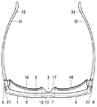
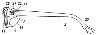
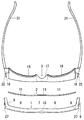
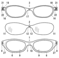
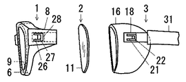
実施形態の作業者防護用ゴーグルは、医療従事者用ゴーグルにしている。使用時の状態は、図1〜図6に示す。フロント1、光学フィルム2と防護体3に分離した取替時の状態は、図7〜図10に示す。
The worker protective goggles of the embodiment are goggles for medical workers. The state at the time of use is shown in FIGS. The state at the time of the replacement | exchange isolate | separated into the
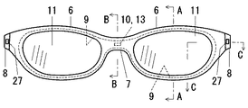
フロント1は、リム6を左右に配置し、左右のリム6の内端同士をブリッジ7で連結している。左右のリム6の外端には、それぞれ、連結筒8を後方に突出して設けている。フロント1は、左右対称にしている。左右のリム6、ブリッジ7と左右の連結筒8は、合成樹脂で一体に成形している。
The
光学フィルム2は、レンズ部11を左右に配置し、左右のレンズ部11の内端同士をブリッジ部12で連結している。左右対称の二眼形状にしている。そして、光学フィルム2は、湾曲可能な透明フィルムにし、防曇加工と反射防止加工を施している。
In the
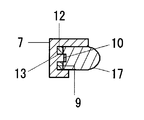
フロント1は、後面に二眼形状の凹部9を設けている。二眼形状の凹部9は、底面の左右に左右のリム6を開口している。二眼形状の凹部9には、二眼形状の光学フィルム2を取外可能に嵌め込んでいる。二眼形状の光学フィルム2は、左右のレンズ部11が左右のリム6を閉鎖している。二眼形状の凹部9は、底面の左右のリム開口部の間に突起部10を設けている。二眼形状の光学フィルム2は、ブリッジ部12に孔部13を設けている。孔部13と突起部10を取外可能に嵌め込んでいる。孔部13と突起部10の嵌め込み機構は、中央位置の一か所にしている。
The
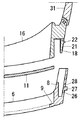
防護体3は、フロント1の左右のリム6にそれぞれ連通する周壁の防護壁16を後方に突出して設けている。左右の防護壁16は、それぞれ、後方への突出長さを周方向に沿って変化させ、後端が着用者の顔面の目の周りに当って接する形状にしている。また、左右の防護壁16は、内端同士を連結部17で連結している。左右の防護壁16の外端には、それぞれ、連結軸18を前方に突出して設けている。防護体3は、左右対称にしている。左右の防護壁16、連結部17と左右の連結軸18は、合成樹脂で一体に成形している。
The
フロント1と防護体3は、前後に連結可能、分離可能にしている。両者が前後に連結した位置は、使用位置にしている。両者が分離した位置は、取替位置にしている。
The
使用位置では、フロント1と防護体3は、光学フィルム2を挟んで前後に連結している。防護体3の左右の防護壁16と連結部17は、前面をフロント1の二眼形状の凹部9に取外可能に嵌め込んでいる。防護体3の左右の防護壁16と連結部17の前面とフロント1の二眼形状の凹部9の底面との間に、二眼形状の光学フィルム2を挟んでいる。左右の防護壁16は、光学フィルム2の左右のレンズ部11を介して左右のリム6に連通している。防護体3の左右の連結軸18は、フロント1の左右の連結筒8に抜出可能に嵌め込んで連結している。
In the use position, the
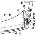
連結軸18は、長方形板状の角軸にし、コの字形状、横倒門型形状の孔ないし切込を左右方向に貫通して掛止め片21を設けている。掛止め片21は、片持梁のように後方に突出している。そして、先端に横荷重を加えると、弾性変形して撓む構成にしている。掛止め片21の先端には、掛け突部22を外方に突出して設けている。掛け突部22は、内方へ押すと引っ込み、押す力がなくなると復元する。
The connecting
連結筒8は、角筒にし、外側壁にコの字形状、横倒門型形状の孔を左右方向に貫通して掛外し片26と掛け孔部28を設けている。掛外し片26は、片持梁のように後方に突出している。そして、先端に横荷重を加えると、弾性変形して撓む構成にしている。掛外し片26の先端には、解除突部27を外方に突出して設けている。掛外し片26は、解除突部27を内方へ押すと内方へ撓み、押す力がなくなると復元する。コの字形状、横倒門型形状の孔は、後部を掛け孔部28にしている。掛け孔部28は、掛外し片26の後側に位置している。
The connecting
連結筒8を連結軸18に差し込むと、連結軸18の外側面に突出した掛け突部22は、連結筒8の外側壁内面に押されて内方へ引っ込み、掛け孔部28に達すると、復元して掛け孔部28に嵌り込む。連結軸18の掛止め片21の掛け突部22が連結筒8の外側壁の掛け孔部28に掛け止まって、連結軸18と連結筒8は抜け止めになる。連結軸18と連結筒8が連結して、フロント1と防護体3が結合される。
When the connecting
連結軸18を連結筒8から抜き出すときは、解除突部27を内方へ押す。すると、掛外し片26が内方へ撓み、掛止め片21を内方へ押す。掛止め片21は内方へ撓み、掛け突部22が内方へ引っ込む。掛け突部22は、掛け孔部28から抜け出る。連結軸18と連結筒8は、抜け止めが解除され、抜出可能、分離可能になる。抜け止め解除状態で連結軸18を連結筒8から抜き出す。連結軸18と連結筒8が分離して、フロント1と防護体3が分離する。
When extracting the connecting
作業者防護用ゴーグルに装着した光学フィルム2を取り外す場合、左右の解除突部27を内方へ押す。すると、左右の掛け突部22が左右の掛け孔部28から抜け出し、抜け止めが解除され、左右の連結軸18が左右の連結筒8から抜出可能になる。次に、左右の連結軸18を左右の連結筒8から抜き出す。防護体3の左右の防護壁16と連結部17は、フロント1の二眼形状の凹部9から取り外す。フロント1と防護体3は、前後に分離する。二眼形状の凹部9に嵌め込まれている光学フィルム2は、後面が解放される。防護体3から分離したフロント1は、使用位置から離れた取替位置で、二眼形状の凹部9から光学フィルム2を取り外す。
When removing the
作業者防護用ゴーグルに装着中の光学フィルム2を取り替えるときは、フロント1と防護体3を分離する。フロント1は、取替作業の行い易い取替位置に配置する。そこで、二眼形状の凹部9に嵌っている光学フィルム2を取り外し、新しい光学フィルム2を嵌め込む。新しい光学フィルム2を装着したフロント1は、防護体3に結合する。即ち、使用位置に戻す。
When replacing the
防護体2は、左右の連結軸18の後端に、それぞれ、テンプル31を蝶番機構で回動可能に取り付けている。左右のテンプル31は、後端に吊り下げ用の孔32を設けている。左右の吊り下げ用の孔32は、それぞれ、左右方向に貫通している。テンプル31は、合成樹脂で成形している。
作業者防護用ゴーグルは、不使用時には、吊り下げ用の孔32を保管庫内のフックに掛け、保管庫に吊り下げて保管する。
The
When the operator protective goggles are not in use, the hanging holes 32 are hung on the hooks in the storage and are suspended and stored in the storage.
[変形例]
本発明は、上記の実施形態に限定されない。次のような変形が例示される。
1.上記の実施形態において、作業者防護用ゴーグルは、着用者の耳に掛けるテンプル31を付けているが、着用者の後頭部を横断するバンドを付ける。
2.上記の実施形態において、テンプル31は、防護体3に付けているが、フロント1に付ける。
3.上記の実施形態において、フロント1と防護体3を分離可能に結合する機構は、フロント1に連結筒8を、防護体3に連結軸18を設けているが、連結筒8を防護体3に、連結軸18をフロント1に設ける。
4.上記の実施形態において、連結軸18と連結筒8を抜出可能に嵌める連結機構は、掛け突部23付き掛止め片22、掛け孔部28と解除突部27付き掛外し片26の構成にしているが、その他の構成にする。
[Modification]
The present invention is not limited to the above embodiment. The following modifications are exemplified.
1. In the above-described embodiment, the worker protective goggles are provided with the
2. In the above embodiment, the
3. In the above embodiment, the mechanism for detachably connecting the
4). In the above embodiment, the coupling mechanism for fitting the
1 フロント
2 光学フィルム、二眼形状の光学フィルム
3 防護体
6 フロントのリム
7 フロントのブリッジ
8 フロントの連結筒
9 フロントの二眼形状の凹部
10 二眼形状の凹部の突起部
11 光学フィルムのレンズ部
12 光学フィルムのブリッジ部
13 ブリッジ部の孔部
16 防護体の防護壁
17 防護体の連結部
18 防護体の連結軸
21 連結軸の掛止め片
22 掛止め片の掛け突部
26 連結筒の掛外し片
27 掛外し片の解除突部
28 連結筒の掛け孔部
31 テンプル
32 テンプルの吊り下げ用の孔
DESCRIPTION OF
Claims (9)
フロントは、リムを左右に配置し、左右のリムの内端同士をブリッジで連結し、
光学フィルムは、レンズ部を左右に配置し、左右のレンズ部の内端同士をブリッジ部で連結して、二眼形状にし、
防護体は、フロントの左右のリムにそれぞれ連通する周壁の防護壁を後方に突出して設け、左右の防護壁を、それぞれ、後端が着用者の顔面の目の周りに当って接する形状にし、
フロントの後面又は防護体の前面には、二眼形状の光学フィルムを着脱可能に取り付け、光学フィルムの左右のレンズ部で左右のリム又は防護壁を閉鎖し、
フロントと防護体は、連結可能、分離可能にし、
フロントと防護体が前後に連結する使用位置で、フロントと防護体の間に光学フィルムを挟み、光学フィルムの左右のレンズ部を介して左右のリムと左右の防護壁を連通する構成にし、
フロントと防護体が分離した取替位置で、二眼形状の光学フィルムの片面を解放する構成にしていることを特徴とする作業者防護用ゴーグル。 Front, with optical film and protective body,
At the front, the rim is placed on the left and right, the inner ends of the left and right rims are connected by a bridge,
An optical film arranges a lens part on either side, connects the inner ends of a lens part on either side with a bridge part, and makes it a binocular shape,
The protective body is provided with a protective wall of a peripheral wall that projects to the left and right rims of the front projecting rearward, and the left and right protective walls are shaped so that their rear ends hit the eyes around the wearer's face, respectively,
A two-lens shaped optical film is detachably attached to the rear surface of the front or the front surface of the protective body, and the right and left rims or protective walls are closed by the left and right lens portions of the optical film,
The front and protective body can be connected and separated,
At the use position where the front and the protective body are connected back and forth, an optical film is sandwiched between the front and the protective body, and the left and right rims are connected to the left and right protective walls via the left and right lens parts of the optical film.
An operator protective goggles characterized in that one side of a binocular-shaped optical film is released at a replacement position where the front and the protective body are separated.
防護体は、左右の端にそれぞれ連結軸又は連結筒を前方に突出して設け、
連結軸は、連結筒に差し込むと抜け止めになって連結する構成にし、また、連結軸は、抜け止めを解除すると連結筒から抜出可能になる構成にし、
連結軸を連結筒に差し込むとフロントと防護体が連結し、連結軸と連結筒の抜け止めを解除するとフロントと防護体が分離可能になる構成にしていることを特徴とする請求項1に記載の作業者防護用ゴーグル。 The front is provided with protruding connecting cylinders or connecting shafts at the left and right ends, respectively,
The protective body is provided with a connecting shaft or a connecting cylinder projecting forward at the left and right ends, respectively.
The connecting shaft is configured to be connected to the connecting cylinder when it is inserted into the connecting cylinder, and the connecting shaft is configured to be able to be extracted from the connecting cylinder when the retaining shaft is released.
2. The structure according to claim 1, wherein the front and the protection body are connected when the connection shaft is inserted into the connection cylinder, and the front and the protection body can be separated when the connection shaft and the connection cylinder are released. Worker protective goggles.
連結筒は、外側壁に受け部と解除部を設け、
連結軸を連結筒に差し込むと、連結軸の外側面の突出部が連結筒の外側壁内面に押されて内方へ引っ込み、掛け孔部に達すると、復元して掛け孔部に嵌り込み、連結軸と連結筒は抜け止めになって連結する構成にし、解除部を押すと、突出部が引っ込んで受け部から抜け出て、抜け止め解除になって連結軸が連結筒から抜出可能になる構成にしていることを特徴とする請求項2に記載の作業者防護用ゴーグル。 The connecting shaft is provided so that the protrusion can be retracted and restored on the outer surface,
The connecting cylinder is provided with a receiving part and a releasing part on the outer wall,
When the connecting shaft is inserted into the connecting tube, the protruding portion of the outer surface of the connecting shaft is pushed by the inner surface of the outer wall of the connecting tube and retracts inward, and when it reaches the hooking hole, it is restored and fitted into the hooking hole, The connecting shaft and the connecting cylinder are connected so that they are prevented from coming off, and when the release part is pushed, the protruding part retracts and comes out of the receiving part, and the connecting shaft can be pulled out of the connecting cylinder by releasing the retaining part. The goggles for worker protection according to claim 2, wherein the goggles for worker protection are provided.
フロントは、二眼形状の凹部の底面の左右のリム開口部の間に突起部を設け、
突起部と孔部は、取外可能に嵌め込んでいることを特徴とする請求項4に記載の作業者防護用ゴーグル。 Binocular optical film has a hole in the bridge,
The front is provided with a protrusion between the left and right rim openings on the bottom surface of the binocular recess,
5. The worker protective goggles according to claim 4, wherein the protrusion and the hole are detachably fitted.
Priority Applications (1)
| Application Number | Priority Date | Filing Date | Title |
|---|---|---|---|
| JP2015001118A JP6393191B2 (en) | 2015-01-06 | 2015-01-06 | Worker protective goggles |
Applications Claiming Priority (1)
| Application Number | Priority Date | Filing Date | Title |
|---|---|---|---|
| JP2015001118A JP6393191B2 (en) | 2015-01-06 | 2015-01-06 | Worker protective goggles |
Publications (2)
| Publication Number | Publication Date |
|---|---|
| JP2016123762A true JP2016123762A (en) | 2016-07-11 |
| JP6393191B2 JP6393191B2 (en) | 2018-09-19 |
Family
ID=56358418
Family Applications (1)
| Application Number | Title | Priority Date | Filing Date |
|---|---|---|---|
| JP2015001118A Active JP6393191B2 (en) | 2015-01-06 | 2015-01-06 | Worker protective goggles |
Country Status (1)
| Country | Link |
|---|---|
| JP (1) | JP6393191B2 (en) |
Cited By (1)
| Publication number | Priority date | Publication date | Assignee | Title |
|---|---|---|---|---|
| CN111228037A (en) * | 2020-03-18 | 2020-06-05 | 上海交通大学医学院附属第九人民医院 | Interchangeable mirror goggles |
Citations (6)
| Publication number | Priority date | Publication date | Assignee | Title |
|---|---|---|---|---|
| JPH0323859A (en) * | 1989-06-21 | 1991-01-31 | Tadayasu Takehara | Protective lens for goggles and method for assembling the same |
| JP3034614U (en) * | 1996-04-24 | 1997-02-25 | コリア オージーケー カムパニ リミテッド | Protective eyewear for sports |
| US6192523B1 (en) * | 2000-01-18 | 2001-02-27 | Qds Injection Molding Inc. | Diving Mask |
| JP3080073U (en) * | 2001-03-07 | 2001-09-14 | 誠加興業股▲ふん▼有限公司 | Wide view goggles for diving |
| JP2002125998A (en) * | 2000-10-20 | 2002-05-08 | Midori Anzen Co Ltd | Dust proof glasses |
| JP2014137597A (en) * | 2013-01-18 | 2014-07-28 | Otos Wing Co Ltd | Electronic protective spectacles for harmful flashlight shielding and anti-glare purpose |
-
2015
- 2015-01-06 JP JP2015001118A patent/JP6393191B2/en active Active
Patent Citations (6)
| Publication number | Priority date | Publication date | Assignee | Title |
|---|---|---|---|---|
| JPH0323859A (en) * | 1989-06-21 | 1991-01-31 | Tadayasu Takehara | Protective lens for goggles and method for assembling the same |
| JP3034614U (en) * | 1996-04-24 | 1997-02-25 | コリア オージーケー カムパニ リミテッド | Protective eyewear for sports |
| US6192523B1 (en) * | 2000-01-18 | 2001-02-27 | Qds Injection Molding Inc. | Diving Mask |
| JP2002125998A (en) * | 2000-10-20 | 2002-05-08 | Midori Anzen Co Ltd | Dust proof glasses |
| JP3080073U (en) * | 2001-03-07 | 2001-09-14 | 誠加興業股▲ふん▼有限公司 | Wide view goggles for diving |
| JP2014137597A (en) * | 2013-01-18 | 2014-07-28 | Otos Wing Co Ltd | Electronic protective spectacles for harmful flashlight shielding and anti-glare purpose |
Cited By (1)
| Publication number | Priority date | Publication date | Assignee | Title |
|---|---|---|---|---|
| CN111228037A (en) * | 2020-03-18 | 2020-06-05 | 上海交通大学医学院附属第九人民医院 | Interchangeable mirror goggles |
Also Published As
| Publication number | Publication date |
|---|---|
| JP6393191B2 (en) | 2018-09-19 |
Similar Documents
| Publication | Publication Date | Title |
|---|---|---|
| EP2191736B1 (en) | Wearable protective device | |
| JP6747296B2 (en) | Surgical face guard, surgical frame and surgical system | |
| AU2016341973B2 (en) | Respirator mask with eyewear interface | |
| KR200485969Y1 (en) | A tight mask for face | |
| TW201721236A (en) | Exchangeable eye glass members | |
| CN105960222A (en) | goggles | |
| US1582164A (en) | Face protector or shield | |
| KR20160145522A (en) | Glasses hanger with anti-fog mask | |
| JP2013253344A (en) | Dustproof hood | |
| JP6393191B2 (en) | Worker protective goggles | |
| JP5223687B2 (en) | Stereoscopic glasses | |
| JP2015099217A (en) | Spectacle front frame with inner frame | |
| JP5557729B2 (en) | Eyeglass frames | |
| JP2015108798A (en) | Dual mounting type protection spectacle | |
| US2446048A (en) | Eyeshield | |
| JP6341559B2 (en) | Face protector and face protector frame | |
| JP3196052U (en) | Worker protective goggles | |
| BRPI0712849A2 (en) | safety goggles including a flexible cable accessory | |
| JP3955432B2 (en) | Glasses having a bridge with a snap | |
| WO2015064875A1 (en) | Lens frame attachment/detachment structure for glasses | |
| CN101473264B (en) | Safety eyewear including a prescription insert | |
| JP3179031U (en) | Glasses | |
| JP2017003714A (en) | Exhalation clouding prevention sheet for spectacle | |
| CN211460828U (en) | Flip type face mask | |
| KR20120054942A (en) | Interchangeable goggle |
Legal Events
| Date | Code | Title | Description |
|---|---|---|---|
| A621 | Written request for application examination |
Free format text: JAPANESE INTERMEDIATE CODE: A621 Effective date: 20170914 |
|
| A977 | Report on retrieval |
Free format text: JAPANESE INTERMEDIATE CODE: A971007 Effective date: 20180726 |
|
| TRDD | Decision of grant or rejection written | ||
| A01 | Written decision to grant a patent or to grant a registration (utility model) |
Free format text: JAPANESE INTERMEDIATE CODE: A01 Effective date: 20180814 |
|
| A61 | First payment of annual fees (during grant procedure) |
Free format text: JAPANESE INTERMEDIATE CODE: A61 Effective date: 20180824 |
|
| R150 | Certificate of patent or registration of utility model |
Ref document number: 6393191 Country of ref document: JP Free format text: JAPANESE INTERMEDIATE CODE: R150 |
|
| R250 | Receipt of annual fees |
Free format text: JAPANESE INTERMEDIATE CODE: R250 |
|
| R250 | Receipt of annual fees |
Free format text: JAPANESE INTERMEDIATE CODE: R250 |
|
| R250 | Receipt of annual fees |
Free format text: JAPANESE INTERMEDIATE CODE: R250 |