JP2016123065A - Speaker stand for placing speaker box thereon - Google Patents
Speaker stand for placing speaker box thereon Download PDFInfo
- Publication number
- JP2016123065A JP2016123065A JP2014267250A JP2014267250A JP2016123065A JP 2016123065 A JP2016123065 A JP 2016123065A JP 2014267250 A JP2014267250 A JP 2014267250A JP 2014267250 A JP2014267250 A JP 2014267250A JP 2016123065 A JP2016123065 A JP 2016123065A
- Authority
- JP
- Japan
- Prior art keywords
- speaker
- speaker box
- support
- box
- gravity
- Prior art date
- Legal status (The legal status is an assumption and is not a legal conclusion. Google has not performed a legal analysis and makes no representation as to the accuracy of the status listed.)
- Pending
Links
Images


Abstract
Description
この発明はスピーカー箱の底部に設置するスピーカーの振動制動に関する装置についてである。The present invention relates to an apparatus related to vibration braking of a speaker installed at the bottom of a speaker box.
従来はスピーカーユニットの振動による歪みをスピーカー箱の底部に、多点接触または面接触によるインシュレーターにて振動の遮断と制動機能を持たせていた。 In the past, distortion caused by vibration of the speaker unit was provided at the bottom of the speaker box with a multi-point or surface contact insulator to provide vibration isolation and braking.
これには次のような欠点があった。多点接触としてのインシュレーターには、スピーカーの振動制御機能が強すぎても、弱すぎても音が悪く聞こえ、最適なものを選択するのが難しい。スピーカーと床面との振動を遮断するために3点ないし4点支持点接触インシュレーターや面接触オーディオボードはスピーカーの底面部を前後左右に動かないように固定することになるので、当該スピーカー箱がねじれやゆがみ歪みのような複雑な歪みを発生させる。This has the following drawbacks. For an insulator as a multi-point contact, even if the vibration control function of the speaker is too strong or too weak, the sound is poor and it is difficult to select the optimum one. In order to cut off the vibration between the speaker and the floor, the 3-point or 4-point support point contact insulator and the surface contact audio board are fixed so that the bottom of the speaker does not move back and forth and left and right. Generate complex distortions such as torsion and distortion.
従来方式については、音が変わるのは物理的に説明はつくが,よい音に改善されたかどうかは聞く側の主観的感性による要素が多いものである。
本発明は以上の課題を解決するためなされたものである。これは従来用いられている多点接触支持型でもなく、面接触支持型でもない。スピーカー箱のスピーカーユニット部に全重心を設定し,ここを線接触支持型の支持体によって支え、回転モーメントの働きによって前記スピーカー箱から発生するひずみを抑えるものである。With regard to the conventional system, it can be physically explained that the sound changes, but whether or not the sound is improved is largely due to the subjective sensitivity of the listener.
The present invention has been made to solve the above problems. This is not a conventionally used multipoint contact support type, nor is it a surface contact support type. The entire center of gravity is set in the speaker unit portion of the speaker box, which is supported by a line contact support type support, and the distortion generated from the speaker box by the action of the rotational moment is suppressed.
本発明は、その課題を解決するために、次のような手段を考えだした。スピーカー箱をのせるスピーカー台であって
(1)前記スピーカー箱の底面部の重心部を、略水平姿勢になるように支持するために、前記スピーカー箱に対して横幅方向に支持体を設ける。
(2)前記スピーカー箱に回転モーメントが働き、前後方向に回転自在となる線接触部材を前記支持体とする。
(3)前記スピーカー箱が平衡を保つために、前記支持体の前部と後部に弾性部材を支持体として設ける。
以上を具備するスピーカー箱をのせるスピーカー台である。In order to solve the problem, the present invention has devised the following means. A speaker base on which a speaker box is mounted. (1) In order to support the center of gravity of the bottom surface of the speaker box in a substantially horizontal position, a support body is provided in a lateral width direction with respect to the speaker box.
(2) A line contact member that is rotatable in the front-rear direction by a rotational moment acting on the speaker box is defined as the support.
(3) In order to keep the speaker box in equilibrium, elastic members are provided as supports on the front and rear portions of the support.
It is a speaker stand which mounts the speaker box which comprises the above.
従来はスピーカー箱の底部を固定すると、スピーカーユニットのマグネット部で生じる反作用の力による運動エネルギーは、前記スピーカー箱の底部で床面を通して放出され、全体の重量を外力として受け止め、そのためねじれやゆがみが発生し歪みとなる。前記マグネット部の反作用による振動はフレーム、ついで前面バッフル、側面、ついで底面部、ついで床の不動の固定部と、複雑な経路をとりその間に歪が発生する。Conventionally, when the bottom of the speaker box is fixed, the kinetic energy due to the reaction force generated in the magnet part of the speaker unit is released through the floor surface at the bottom of the speaker box, and the entire weight is received as an external force, so that twist and distortion are caused. Generated and distorted. The vibration due to the reaction of the magnet part takes a complicated path between the frame, then the front baffle, the side face, then the bottom face part, and then the stationary fixed part of the floor, and distortion occurs between them.
本発明により、スピーカーユニットのマグネット部からの反作用で生じる不要振動は重心部を中心とする回転モーメントとして受け止め、それを運動エネルギーとして放出し、スピーカー箱の前部と後部とで消費する。床とつながらないため外力が働かず重心の変化がないため前記スピーカー箱は歪みのもととなるストレスが加わらないので、不要な振動の発生を抑える効果がある。マグネット部の反作用の力を、スピーカー箱の全重量を重心であるマグネット部でうけとめる。図2に基づいて説明すると、全体の重心の位置(10)は釣合い状態が反作用の力Fによりずれると益々釣合い状態から遠ざかる不安定な釣合いとしている。ここで前記反作用の力Fにより重心部が移動しようとすると、前記スピーカー箱(1)は釣合がずれて斜めに傾き、回転モーメントとしての運動となる。このようにして回転モーメントは運動エネルギーとなる。
全体の重心の位置(10)を中心に回転モーメントが働き、この重心の位置(10)は移動がないので前記反作用による力Fな内力として働く。この内力はすべて前方と後方に運動エネルギーとして放散、消費される。前記スピーカー箱(1)はストレスによる歪がかかりにくくなる。この反作用による力Fは外力としての床とつながらずこれによる加振される歪みは少ないという効果がある。According to the present invention, unnecessary vibration generated by the reaction from the magnet portion of the speaker unit is received as a rotational moment centered on the center of gravity, and is released as kinetic energy, which is consumed by the front and rear portions of the speaker box. Since the speaker box is not connected to the floor and no external force is applied and the center of gravity does not change, the speaker box is not subjected to stress that causes distortion, and thus has an effect of suppressing generation of unnecessary vibration. The force of the reaction of the magnet part is captured by the magnet part which is the center of gravity of the total weight of the speaker box. If it demonstrates based on FIG. 2, the position (10) of the center of gravity of the whole is an unstable balance which will move away from a balanced state more and more if a balanced state shifts | deviates by the force F of reaction. Here, when the center of gravity is about to move by the reaction force F, the speaker box (1) is out of balance and tilted obliquely, resulting in movement as a rotational moment. In this way, the rotational moment becomes kinetic energy.
A rotational moment acts around the position of the center of gravity (10) as a whole, and this center of gravity position (10) does not move, so it acts as an internal force F due to the reaction. All this internal force is dissipated and consumed as kinetic energy forward and backward. The speaker box (1) is less susceptible to distortion due to stress. The force F due to this reaction is not connected to the floor as an external force, and there is an effect that the distortion caused by this is small.
本発明により、前記スピーカー箱(1)の底部の重心の位置(11)に線接触する支持体(13)を備えることによって,スピーカーユニット(14)とマグネット部を含むスピーカー箱(1)の全重量が全体の重心の位置(10)にかかり振動の加速を受け止める。前記重心の位置(10)にマグネット部があるのでスピーカーユニット(14)の重量をMsp、又スピーカー箱の重量をMboxとすれば、コーン振動による反作用の力F1は(Msp+Mbox)×a−−−−(1), a:マグネット部の加速度。 一方、コーン振動板による作用の力FはF=bmで表わされる。b:コーン振動板の加速度、m:コーン振動板の重量とする。
作用の力と反作用の力は等しいので次式が成り立つ。
(Msp+Mbox)×a=bm−−−−(2),従ってマグネット部の加速度aは
a=mb/(Msp+Mbox)−−−−(3).これはコーンの振動による反動の力を、スピーカー箱の全重量を重心として、この振動エネルギーを受け止めることになる。従って反作用の力をマグネットの重さだけで受け止めるより振動を抑える効果がある。加速度の比率=コーンの重量/スピーカー箱の全重量である。
コーンの重量が10g、スピーカー箱の全重量を20Kgなら、マグネット部の加速度の比率はa/b=1/2000,となり振動の制動効果は大きいものとなる。According to the present invention, by providing the support (13) in line contact with the position (11) of the center of gravity of the bottom of the speaker box (1), the entire speaker box (1) including the speaker unit (14) and the magnet part is provided. The weight is applied to the position (10) of the entire center of gravity, and the acceleration of vibration is received. If the weight of the speaker unit (14) there is a magnet unit in position (10) of the center of gravity M sp, also the weight of the speaker box and M box, the force F 1 of the reaction according to the cone vibration (M sp + M box ) × a ---- (1), a: acceleration of the magnet part. On the other hand, the force F of action by the cone diaphragm is represented by F = bm. b: acceleration of cone diaphragm, m: weight of cone diaphragm.
Since the force of action is equal to the force of reaction, the following equation holds.
(M sp + M box ) × a = bm −−−− (2), therefore, the acceleration a of the magnet portion is a = mb / (M sp + M box ) −−−− (3). This means that the reaction force caused by the vibration of the cone receives the vibration energy with the total weight of the speaker box as the center of gravity. Therefore, there is an effect of suppressing the vibration rather than receiving the reaction force only by the weight of the magnet. Acceleration ratio = cone weight / total weight of the speaker box.
If the weight of the cone is 10 g and the total weight of the speaker box is 20 kg, the acceleration ratio of the magnet portion is a / b = 1/2000, and the vibration damping effect is large.
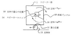
スピーカーユニット(14)のマグネット部が反作用の力によって振動すると、フレームを通して前面バッフル(18)に伝わる。この前面バッフル(18)からの振動エネルギーはこのマグネット部の位置を中心に回転モーメントとして働き、マグネット部の重心の位置は変わらない。このとき、支持体(13)は丸棒形のもので前記前面バッフル(18)が前方に傾くと、これが反時計方向にまわり、後方に傾く時は、時計方向に回る。この動作によって全体の重心の位置(10)を中心として回転モーメントが働く。これによってこの重心の位置(10)を境にして前記バッフル面(18)の反作用の力による振動は、この面の上部と下部では位相が反転し、逆相関係になり、互いの音圧は相殺される。重心を中心に空間に放出される音圧は、上部バッフル面は正相レベル(15)とすれば下部バッフル面からは逆相レベル(16)となり、バッフル面からのマグネット部の反動による歪音は空中で相殺され消える効果がある。When the magnet part of the speaker unit (14) vibrates due to the reaction force, it is transmitted to the front baffle (18) through the frame. The vibration energy from the front baffle (18) acts as a rotational moment around the position of the magnet part, and the position of the center of gravity of the magnet part does not change. At this time, the support (13) has a round bar shape. When the front baffle (18) is tilted forward, it rotates counterclockwise, and when it is tilted backward, it rotates clockwise. By this operation, a rotational moment acts around the position (10) of the entire center of gravity. As a result, the vibration caused by the reaction force of the baffle surface (18) at the position of the center of gravity (10) is reversed in phase at the upper and lower portions of this surface, and is in an opposite phase relationship. Offset. The sound pressure released into the space centered on the center of gravity is the negative phase level (16) from the lower baffle surface if the upper baffle surface is the normal phase level (15), and the distorted sound due to the reaction of the magnet part from the baffle surface Is offset in the air and disappears.
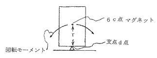
スピーカー箱の底面部に取り付ける3角棒などの転がらない支持体の線接触部は、ここを支点として回転モーメントが働く。図3と図4に基づいて説明すると、図3はスピーカー箱がその底面部を直接床に置かれたものを示す。スピーカーユニットのマグネット部の反作用によって外力となって固定された床とでバッフル面を振動させる。これによってスピーカー箱は強いストレスが生じ、捩れや歪みによって歪み音が発生する。図4に基づいて説明すると、重心の位置にあるマグネット(6)C点は支持体(7)を中心支点として回転モーメントが働く。コーンの作用の力の反作用によってスピーカーユニットのマグネット部(6)の回転モーメントが働く時、この速度VはV=rw−−−(4) r:支点d点から前記c点までの距離、w:回転の角速度である。
(4)式からdV/dt=aは加速度でdw/dt=fは角加速度となり
a=fr −−−(5)と示される。一方、If=F1r−−−(6).Iは慣性モーメントで、I=r2×(Msp+Mbox)である。ここでMsp:スピーカーマグネット部の重量、Mbox:スピーカー箱の重量、F1:反作用の力とする。
(6)よりr2f×(Msp+Mbox)=F1r −−−(7)
(5)式よりf=a/rとにより、F1=a× (Msp+Mbox)−−−(8)
コーンの振動の 作用の力FはF=bm−−−(9) b:コーンの加速度、m:コーンの重量、作用の力F=反作用の力F1なので(8)式と(9)式よりマグネット部の加速度a= mb/(Msp+Mbox)−−−(10),(10)式よりマグネット部の加速度aはコーンの加速度bに比較して大幅に小さい。例えば、コーンの重量が10gでスピーカーユニットの重量が2Kg、スピーカー箱のそれが20Kgとすれば、a=10/22000=1/2200となり、反動によるマグネット部の振動は抑えられる。さらに回転モーメントによる運動で外力とつながらないので歪みは外力となる床に直接置いた場合に比べて、これに起因する歪みは発生しない効果がある。The line contact portion of the support body that does not roll, such as a triangular bar attached to the bottom surface portion of the speaker box, has a rotational moment acting here. Referring to FIG. 3 and FIG. 4, FIG. 3 shows a speaker box having its bottom face directly placed on the floor. The baffle surface is vibrated with the floor fixed as an external force by the reaction of the magnet part of the speaker unit. As a result, a strong stress is generated in the speaker box, and a distortion sound is generated by twisting or distortion. If it demonstrates based on FIG. 4, the magnet (6) C point in the position of a gravity center will work a rotational moment centering on a support body (7). When the rotational moment of the magnet unit (6) of the speaker unit is exerted by the reaction of the cone action force, this speed V is V = rw --- (4) r: distance from the fulcrum point d to the point c, w : Angular velocity of rotation.
From equation (4), dV / dt = a is acceleration, dw / dt = f is angular acceleration, and a = fr (5). On the other hand, If = F 1 r ---- (6). I is a moment of inertia and is I = r 2 × (M sp + M box ). Here, M sp is the weight of the speaker magnet, M box is the weight of the speaker box, and F 1 is the reaction force.
From (6), r 2 f × (M sp + M box ) = F 1 r −−− (7)
(5) From the equation, f 1 = a / r, F 1 = a × (M sp + M box ) −−− (8)
The force F of the cone vibration action is F = bm --- (9) b: cone acceleration, m: cone weight, action force F = reaction force F 1 (8) and (9) more magnet portion acceleration a = mb / (M sp + M box) --- (10), (10) the acceleration a of the magnet unit is much smaller than the acceleration b of the cone from the equation. For example, if the weight of the cone is 10 g, the weight of the speaker unit is 2 kg, and that of the speaker box is 20 kg, a = 10/22000 = 1/200, and the vibration of the magnet part due to the reaction can be suppressed. Furthermore, since the movement by the rotational moment does not connect to the external force, the distortion is not generated as compared with the case where the distortion is placed directly on the floor that becomes the external force.
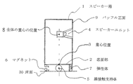
以下、本発明を実施するための形態について図1に基づいて説明する。スピーカー箱(1)の底面部(2)の重心の位置(3)に、スピーカーユニット(4)の取り付けられているバッフル正面(9)と平行方向、つまり当該スピーカー箱(1)の横幅方向に線接触する支持体(5)を設ける。ここで線接触とは前記スピーカー箱(1)の底面部(2)と前記支持体(5)との間、又床面(30)と前記支持体(5)との間が、幾何学的に1本の線になるように接触することを言う。
また、点接触であっても1列に直線的に並べた同等の線接触機能を有するものも含む。また面接触であっても底面部(2)の平衡が取り難い不安定な釣合いとなるものも含む。ここで前記スピーカー箱(1)は前記支持体(5)によって重心の位置(3)で線接触支持されているので、不平衡となりやすく、平衡をとるために前記支持体(5)の前部と後部にマグネット(6)やスポンジ等の弾性体(7)を設け、平衡をとっている。前記支持体(5)は重心の位置(3)にあるため、ほぼ全重量がここにかかり、前記マグネット(6)やスポンジ等の前記弾性体(7)部には単に平衡を保つために支えるだけの荷重がかかるにすぎない。補助的な支えである。コーンが動いてもその反動で前記スピーカー箱(1)の全体の重心の位置は変わらないので、ここを中心として前、後方向に回転モーメントが働き、横方向の変化はしない。この回転モーメントの働きをさせるため、前記支持体(5)は転がる丸棒状等の機能を持たせる構造とする。また、前記支持体(5)を中心に慣性モーメントの働きを持たせるために3角状等の構造にする。転がらないものもある。Hereinafter, an embodiment for carrying out the present invention will be described with reference to FIG. At the position (3) of the center of gravity of the bottom surface portion (2) of the speaker box (1), in the direction parallel to the front surface (9) of the baffle to which the speaker unit (4) is attached, that is, in the width direction of the speaker box (1). A support (5) in line contact is provided. Here, the line contact means that there is a geometrical distance between the bottom surface (2) of the speaker box (1) and the support (5) and between the floor (30) and the support (5). To contact so that it becomes one line.
Moreover, even if it is a point contact, what has the equivalent line contact function arranged in a line linearly is also included. Moreover, even if it is a surface contact, the thing which becomes an unstable balance where it is difficult to take a balance of a bottom face part (2) is included. Here, since the speaker box (1) is line-contact supported by the support (5) at the position of the center of gravity (3), the speaker box (1) is likely to be unbalanced and the front part of the support (5) is in order to be balanced. And an elastic body (7) such as a magnet (6) or sponge is provided at the rear part to achieve equilibrium. Since the support (5) is located at the center of gravity (3), almost the entire weight is applied here, and the elastic body (7) such as the magnet (6) or sponge is supported only to maintain equilibrium. Only a load is applied. It is an auxiliary support. Even if the cone moves, the position of the entire center of gravity of the speaker box (1) does not change due to the reaction, so that a rotational moment acts forward and backward around this, and no lateral change occurs. In order to make this rotational moment work, the support (5) is structured to have a rolling bar-like function. In addition, a triangular structure or the like is used to provide the moment of inertia around the support (5). Some do not roll.
図2に基づいて説明すると、全体の重心の位置(10)にあるマグネット部はコーンが振動するとその反作用で振動する。線接触する前記支持体(13)を全体の重心の位置(10)底面部の重心の位置(11)に横幅方向に設ける。
全体の重心の位置(10)を中心に回転モーメントが働き、前記前面バッフル(18)を前後に振動させる。ここでは前記支持体(13)は転がる円筒状のものを使っている。前面バッフル(18)が前方向に傾く時は前記転がる丸棒状の支持体(13)は反時計方向に回り、一方前記前面バッフル(18)が後方に傾く時は時計方向に回る。この運動によって前記全体の重心の位置(10)つまりスピーカーユニットのマグネットの位置を中心に回転モーメントが働く。
反作用の力によっては重心の位置を変化させず、回転運動にすることである。
コーンの振動によるマグネット部からの反作用の力を内力として消費し、外力とつながらず、重心の位置が変化せず、外力による歪みの原因となる床面とはフローテイングになっている。Referring to FIG. 2, when the cone vibrates, the magnet portion at the center of gravity position (10) vibrates due to its reaction. The support (13) in line contact is provided in the lateral width direction at the position of the center of gravity (10) and the position of the center of gravity (11) of the bottom portion.
A rotational moment acts around the position of the center of gravity (10) as a whole, causing the front baffle (18) to vibrate back and forth. Here, the cylindrical support body (13) is used. When the front baffle (18) tilts forward, the rolling rod-like support (13) rotates counterclockwise, while when the front baffle (18) tilts backward, it rotates clockwise. By this movement, a rotational moment acts around the position of the center of gravity (10), that is, the position of the magnet of the speaker unit.
Depending on the reaction force, the position of the center of gravity is not changed, but a rotational motion is made.
The reaction force from the magnet part due to the vibration of the cone is consumed as an internal force and is not connected to the external force, the position of the center of gravity does not change, and the floor surface that causes distortion due to the external force is floating.
図5は本発明によるスピーカー台の斜視図を示す。線接触支持体(20)の両側にこれを支えるための支持体(21)と同(22)を設ける。第1の支持部材(24)の上部に前記支持体(21)と(22)を固定する。
前記支持体(21)と同(22)の上面部にスポンジ等の弾性体(23)と同(25)を設ける。これはスピーカー箱の底部を、前記線接触支持体(20)を支点として平衡を保つための働きをする。前記線接触支持体(20)の中心部とそれに面する前記支持体(21)と同(22)の側面部との間にスポンジ等の弾性体(26)と同(27)を設け、前記線接触支持体(20)を支える。前記線接触支持体(20)がその重心の位置を中心に回転、振動するためである。図6は前記線接触支持体(20)の斜視図であり半径rの丸棒状のもの(29)のその重心の位置を対称にし、両側をカットしたものである。これによって省スペースとなり、かつ可動範囲内においては丸棒状の線接触支持体としての機能を果たしている。FIG. 5 shows a perspective view of a speaker stand according to the present invention. The support (21) and (22) for supporting this are provided on both sides of the line contact support (20). The supports (21) and (22) are fixed to the upper part of the first support member (24).
The elastic body (23) and the same (25) such as sponge are provided on the upper surface portion of the support (21) and (22). This functions to keep the bottom of the speaker box balanced with the line contact support (20) as a fulcrum. An elastic body (26) and the same (27) such as a sponge are provided between the central portion of the line contact support (20) and the side faces of the support (21) and (22) facing the same, Supports the line contact support (20). This is because the line contact support (20) rotates and vibrates around the center of gravity. FIG. 6 is a perspective view of the line contact support (20), in which the center of gravity of a round bar (29) having a radius r is made symmetrical and both sides are cut. This saves space and functions as a round bar-like line contact support within the movable range.
1 スピーカー箱
2 底面部
3 重心位置
4 スピーカーユニット
5 線接触支持−1
6 マグネット
7 弾性体
9 バッフル正面図
10 床面
19 全体の重心の位置c点
22,23,24、25 弾性体
27,28 支持体
29 丸棒DESCRIPTION OF SYMBOLS 1 Speaker box 2
6
Claims (1)
Priority Applications (1)
| Application Number | Priority Date | Filing Date | Title |
|---|---|---|---|
| JP2014267250A JP2016123065A (en) | 2014-12-24 | 2014-12-24 | Speaker stand for placing speaker box thereon |
Applications Claiming Priority (1)
| Application Number | Priority Date | Filing Date | Title |
|---|---|---|---|
| JP2014267250A JP2016123065A (en) | 2014-12-24 | 2014-12-24 | Speaker stand for placing speaker box thereon |
Publications (2)
| Publication Number | Publication Date |
|---|---|
| JP2016123065A true JP2016123065A (en) | 2016-07-07 |
| JP2016123065A5 JP2016123065A5 (en) | 2018-09-13 |
Family
ID=56329221
Family Applications (1)
| Application Number | Title | Priority Date | Filing Date |
|---|---|---|---|
| JP2014267250A Pending JP2016123065A (en) | 2014-12-24 | 2014-12-24 | Speaker stand for placing speaker box thereon |
Country Status (1)
| Country | Link |
|---|---|
| JP (1) | JP2016123065A (en) |
Citations (2)
| Publication number | Priority date | Publication date | Assignee | Title |
|---|---|---|---|---|
| JPS54137322A (en) * | 1978-04-18 | 1979-10-25 | Mitsubishi Electric Corp | Support for speaker box |
| JPS54140527A (en) * | 1978-04-24 | 1979-10-31 | Mitsubishi Electric Corp | Speaker box support |
-
2014
- 2014-12-24 JP JP2014267250A patent/JP2016123065A/en active Pending
Patent Citations (2)
| Publication number | Priority date | Publication date | Assignee | Title |
|---|---|---|---|---|
| JPS54137322A (en) * | 1978-04-18 | 1979-10-25 | Mitsubishi Electric Corp | Support for speaker box |
| JPS54140527A (en) * | 1978-04-24 | 1979-10-31 | Mitsubishi Electric Corp | Speaker box support |
Similar Documents
| Publication | Publication Date | Title |
|---|---|---|
| CN202868235U (en) | Bracket and composite member formed by same and horizontal supporting surface | |
| US8121333B2 (en) | Suspension device for microphone | |
| CA2726665C (en) | Stereo speaker stand | |
| JP5649223B2 (en) | System and method for reducing baffle vibration | |
| US8536435B2 (en) | Support structure and process for percussion instruments | |
| JP5741993B2 (en) | Parts supply device | |
| KR20170085804A (en) | Multi-use rotational monitor stand | |
| JP2016123065A (en) | Speaker stand for placing speaker box thereon | |
| CN207378298U (en) | A kind of pipeline suspension damper of multi-buffer | |
| JP2012116336A (en) | Caster which has buffer mechanism | |
| JP4312062B2 (en) | Speaker mounting structure | |
| JP2016173417A (en) | Drum stand and drum device equipped with the same | |
| CN105142066A (en) | Vibration reduction loudspeaker box system | |
| JP7231933B2 (en) | speaker device | |
| CN103836109B (en) | A kind of hanging vibration isolator of low coupled wall and vibration isolator group | |
| CN105245982A (en) | Vibration-reducing loudspeaker box system | |
| JP6311733B2 (en) | Deck under cabin | |
| JP4819963B1 (en) | Speaker | |
| JP2016123065A5 (en) | ||
| CN105120399A (en) | Sound box system | |
| US20190272854A1 (en) | Hard disk drive vibration-proof structure | |
| JP6733018B1 (en) | Anti-vibration equipment and suspension support structure | |
| JP5353075B2 (en) | Linear feeder | |
| RU2009148380A (en) | STAND FOR COMPREHENSIVE DETERMINATION OF MASS-INERTIAL CHARACTERISTICS OF AXISYMMETRIC ROTORS | |
| JP2015231067A (en) | Video display device |
Legal Events
| Date | Code | Title | Description |
|---|---|---|---|
| A621 | Written request for application examination |
Free format text: JAPANESE INTERMEDIATE CODE: A621 Effective date: 20171113 |
|
| A521 | Request for written amendment filed |
Free format text: JAPANESE INTERMEDIATE CODE: A523 Effective date: 20180606 |
|
| A521 | Request for written amendment filed |
Free format text: JAPANESE INTERMEDIATE CODE: A523 Effective date: 20180717 |
|
| A977 | Report on retrieval |
Free format text: JAPANESE INTERMEDIATE CODE: A971007 Effective date: 20180913 |
|
| A131 | Notification of reasons for refusal |
Free format text: JAPANESE INTERMEDIATE CODE: A131 Effective date: 20181002 |
|
| A521 | Request for written amendment filed |
Free format text: JAPANESE INTERMEDIATE CODE: A523 Effective date: 20181130 |
|
| A131 | Notification of reasons for refusal |
Free format text: JAPANESE INTERMEDIATE CODE: A131 Effective date: 20190514 |
|
| A02 | Decision of refusal |
Free format text: JAPANESE INTERMEDIATE CODE: A02 Effective date: 20191203 |