JP2016116745A - Tilt determination device, tilt determination system, tilt determination method and program - Google Patents

Tilt determination device, tilt determination system, tilt determination method and program Download PDF

Info

Publication number
JP2016116745A
JP2016116745A JP2014258824A JP2014258824A JP2016116745A JP 2016116745 A JP2016116745 A JP 2016116745A JP 2014258824 A JP2014258824 A JP 2014258824A JP 2014258824 A JP2014258824 A JP 2014258824A JP 2016116745 A JP2016116745 A JP 2016116745A
Authority
JP
Japan
Prior art keywords
inclination
unit
user
information
exercise
Prior art date
Legal status (The legal status is an assumption and is not a legal conclusion. Google has not performed a legal analysis and makes no representation as to the accuracy of the status listed.)
Pending
Application number
JP2014258824A
Other languages
Japanese (ja)
Inventor
雅文 佐藤
Masafumi Sato
雅文 佐藤
Current Assignee (The listed assignees may be inaccurate. Google has not performed a legal analysis and makes no representation or warranty as to the accuracy of the list.)
Seiko Epson Corp
Original Assignee
Seiko Epson Corp
Priority date (The priority date is an assumption and is not a legal conclusion. Google has not performed a legal analysis and makes no representation as to the accuracy of the date listed.)
Filing date
Publication date
Application filed by Seiko Epson Corp filed Critical Seiko Epson Corp
Priority to JP2014258824A priority Critical patent/JP2016116745A/en
Priority to US14/965,375 priority patent/US20160175650A1/en
Publication of JP2016116745A publication Critical patent/JP2016116745A/en
Pending legal-status Critical Current

Links

Images

Abstract

PROBLEM TO BE SOLVED: To provide a tilt determination device which can determine whether the tilt of exercise equipment before the start of an exercise falls within a proper range, a tilt determination system, a tilt determination method and a program.SOLUTION: A tilt determination device 20 comprises a tilt calculation unit 211 that uses an output signal from an inertia sensor to calculate the tilt of exercise equipment before the start of an exercise, and a determination unit 212 that determines whether the tilt of exercise equipment falls within a reference range determined on the basis of information on the exercise equipment and information on a user body.SELECTED DRAWING: Figure 6

Description

本発明は、傾き判定装置、傾き判定システム、傾き判定方法及びプログラムに関する。   The present invention relates to an inclination determination apparatus, an inclination determination system, an inclination determination method, and a program.

特許文献1では、ユーザーの後方からゴルフスイング運動をカメラ等で撮影し、撮影した画像からスイングプレーンを特定し、スイングプレーンを表示すると共に、スイングプレーンの面積を測定して表示する手法が開示されている。スイングプレーンとは、腕、クラブシャフト、及びクラブヘッド(あるいはクラブシャフトとクラブヘッド)によって構成される線分が、ゴルフスイング運動中に移動して軌跡として残る平面であり、一般に、スイング後方から見た際に、スイングプレーンができるだけ面積を持たずに線分に近い方が良いスイングとされている。従って、特許文献1の手法によれば、ユーザーは、スイングプレーンの面積の情報から、スイングの良し悪しを定量的に知ることができる。   Patent Document 1 discloses a method of photographing a golf swing motion from behind the user with a camera, specifying a swing plane from the photographed image, displaying the swing plane, and measuring and displaying the area of the swing plane. ing. A swing plane is a plane in which a line segment constituted by an arm, a club shaft, and a club head (or a club shaft and a club head) moves during a golf swing motion and remains as a trajectory. The swing plane is considered to be a better swing if it is closer to the line segment with as little area as possible. Therefore, according to the method of Patent Document 1, the user can quantitatively know whether the swing is good or bad from the information of the area of the swing plane.

特開2009−20897号公報JP 2009-20897 A

しかしながら、スイングプレーンの面積が小さくても、スイングの軌道によってはフック系やスライス系の打球となることもあり、必ずしも良いスイングとは限らない。そこで、ゴルフスイングの指導にあたっては、シャフトプレーンおよびホーガンプレーン等の指標が用いられる場合がある。シャフトプレーンとは、ゴルフのアドレス時(静止状態)においてゴルフクラブのシャフトの長軸方向とターゲットライン(打球方向)とで構成される面であり、ホーガンプレーンとは、ゴルフのアドレス時において、ゴルファーの肩付近(肩や首の付け根など)とゴルフクラブのヘッド(あるいは、ボール)を結ぶ仮想線とターゲットライン(打球の目標方向)とで構成される面である。このシャフトプレーンとホーガンプレーンにより挟まれる領域はVゾーンと呼ばれ、ダウンスイング時にゴルフクラブの軌跡がVゾーンに入っていればストレート系の打球になることが知られている。従って、ダウンスイング時にゴルフクラブの軌跡がVゾーンに入っているか否かによってスイングの良し悪しを評価することができる。   However, even if the area of the swing plane is small, depending on the trajectory of the swing, it may be a hook-type or slice-type hit ball, and it is not always a good swing. Therefore, in the guidance of the golf swing, an index such as a shaft plane and a Hogan plane may be used. The shaft plane is a plane composed of the major axis direction of the golf club shaft and the target line (direction of hitting ball) at the time of golf addressing (still state), and the Hogan plane is a golfer at the time of golf addressing. Is a plane composed of a virtual line connecting the vicinity of the shoulder (such as the base of the shoulder and neck) and the head (or ball) of the golf club and a target line (target direction of the hit ball). A region sandwiched between the shaft plane and the Hogan plane is called a V zone, and it is known that if a golf club track is in the V zone during a downswing, it becomes a straight hit ball. Therefore, the quality of the swing can be evaluated based on whether or not the golf club locus is in the V zone during the downswing.

Vゾーンを特定するためには、アドレス姿勢時のゴルフクラブのシャフトの傾きを求める必要があるが、従来の手法では、運動開始前にユーザーがアドレス姿勢をとっていない時のシャフトの傾きを求めてしまう場合があり、この場合、シャフトの傾きが適正な範囲にないので、あり得ないVゾーンが生成される可能性があった。このように、運動開始前のシャフトの傾きが適正な範囲であるか否かを判定できなければ、これ以外にも、例えば、ユーザーに対して運動開始の許可を誤って行ってしまうなど、様々な問題も生じ得る。そして、これらの問題はゴルフスイング以外の様々な運動においても生じ得る。   In order to specify the V zone, it is necessary to obtain the inclination of the shaft of the golf club at the address posture, but in the conventional method, the inclination of the shaft when the user does not take the address posture is determined before starting the exercise. In this case, since the inclination of the shaft is not in an appropriate range, an impossible V zone may be generated. In this way, if it is not possible to determine whether the inclination of the shaft before the start of the exercise is within an appropriate range, there are various other cases such as erroneously permitting the user to start the exercise, for example. Problems can also arise. These problems can also occur in various exercises other than golf swings.

本発明は、以上のような問題点に鑑みてなされたものであり、本発明のいくつかの態様によれば、運動開始前の運動器具の傾きが適正な範囲に含まれるか否かを判定可能な傾き判定装置、傾き判定システム、傾き判定方法及びプログラムを提供することができる。   The present invention has been made in view of the above problems, and according to some aspects of the present invention, it is determined whether or not the inclination of the exercise apparatus before the start of exercise is within an appropriate range. A possible tilt determination device, tilt determination system, tilt determination method, and program can be provided.

本発明は前述の課題の少なくとも一部を解決するためになされたものであり、以下の態様または適用例として実現することが可能である。   SUMMARY An advantage of some aspects of the invention is to solve at least a part of the problems described above, and the invention can be implemented as the following aspects or application examples.

[適用例1]
本適用例に係る傾き判定装置は、慣性センサーの出力信号を用いて、運動開始前の運動器具の傾きを算出する傾き算出部と、前記運動器具の傾きが、前記運動器具に関する情報とユーザーの身体情報とに基づいて決定される基準範囲に含まれるか否かを判定する判定部と、を含む。
[Application Example 1]
The inclination determination device according to this application example uses an output signal of the inertial sensor to calculate an inclination of the exercise equipment before starting exercise, and the inclination of the exercise equipment includes information on the exercise equipment and the user's And a determination unit that determines whether or not it is included in a reference range determined based on physical information.

慣性センサーは、加速度や角速度等の慣性量を計測可能なセンサーであればよく、例えば、加速度や角速度を計測可能な慣性計測ユニット(IMU:Inertial Measurement Unit)でもよい。また、慣性センサーは、例えば、運動器具又はユーザーの部位に取り付けられ、運動器具やユーザーに対して脱着可能であってもよいし、運動器具に内蔵されるなど、運動器具に固定されていて取り外すことができないものでもよい。   The inertial sensor may be any sensor that can measure an inertia amount such as acceleration or angular velocity, and may be, for example, an inertial measurement unit (IMU) that can measure acceleration or angular velocity. In addition, the inertial sensor may be attached to the exercise equipment or the user's site, and may be detachable from the exercise equipment or the user, or may be fixed to the exercise equipment such as being incorporated in the exercise equipment. Something that can't be done.

運動器具は、各種の運動に用いられる器具であり、例えば、ゴルフクラブ、テニスラケット、野球のバット、ホッケーのスティック等のスイングに用いられる器具であってもよい。   The exercise apparatus is an apparatus used for various types of exercise, and may be an apparatus used for swinging golf clubs, tennis rackets, baseball bats, hockey sticks, and the like.

傾き算出部は、運動開始前の運動器具の傾きを直接的に算出してもよいし、運動器具の傾きを特定可能な情報(例えば、運動器具に対する相対的な位置や姿勢が既知である場合の慣性センサーの検出軸の傾きあるいは慣性センサーの姿勢角)を算出することにより、運動器具の傾きを間接的に算出してもよい。また、判定部は、運動器具の傾きが基準範囲に含まれるか否かを直接的に判定してもよいし、運動器具の傾きを特定可能な情報が、運動器具の傾きの基準範囲に対応する所望の範囲に含まれるか否かを判定することにより、運動器具の傾きが基準範囲に含まれるか否かを間接的に判定してもよい。   The inclination calculation unit may directly calculate the inclination of the exercise equipment before the start of exercise, or information that can specify the inclination of the exercise equipment (for example, when the relative position or posture with respect to the exercise equipment is known) The inclination of the exercise apparatus may be indirectly calculated by calculating the inclination of the detection axis of the inertia sensor or the attitude angle of the inertia sensor. The determination unit may directly determine whether or not the inclination of the exercise equipment is included in the reference range, and information that can specify the inclination of the exercise equipment corresponds to the reference range of the inclination of the exercise equipment. It may be determined indirectly whether or not the inclination of the exercise apparatus is included in the reference range by determining whether or not it is included in the desired range.

本適用例に係る傾き判定装置は、ユーザーが運動開始前に適正な基本姿勢をとった場合には、運動器具やユーザーの身体に応じて運動器具の傾きの適正な範囲が決まることに着目し、運動開始前の運動器具の傾きが、運動器具に関する情報とユーザーの身体情報とに基づいて決定される基準範囲に含まれるか否かを判定する。従って、本適用例に係る傾き判定装置によれば、ユーザーの運動開始前の運動器具の傾きが適正な範囲に含まれるか否かを判定することができる。   The tilt determination device according to this application example focuses on the fact that the appropriate range of tilt of the exercise equipment is determined according to the exercise equipment and the user's body when the user takes an appropriate basic posture before starting the exercise. Then, it is determined whether or not the inclination of the exercise device before the start of exercise is included in a reference range determined based on the information related to the exercise device and the physical information of the user. Therefore, according to the inclination determination apparatus according to the application example, it is possible to determine whether or not the inclination of the exercise apparatus before the user starts exercising is included in an appropriate range.

[適用例2]
上記適用例に係る傾き判定装置において、前記身体情報は、身長、腕の長さ及び脚の長さの少なくとも1つの情報を含んでもよい。
[Application Example 2]
In the tilt determination apparatus according to the application example described above, the body information may include at least one information of a height, an arm length, and a leg length.

本適用例に係る傾き判定装置によれば、ユーザーの運動開始前の運動器具の傾きが、ユーザーの体格を考慮した適正な範囲に含まれるか否かを判定することができる。   According to the inclination determination apparatus according to this application example, it is possible to determine whether or not the inclination of the exercise apparatus before the user's exercise is included in an appropriate range in consideration of the user's physique.

[適用例3]
上記適用例に係る傾き判定装置において、前記身体情報は、さらに性別の情報を含んでもよい。
[Application Example 3]
In the inclination determination apparatus according to the application example, the physical information may further include sex information.

本適用例に係る傾き判定装置によれば、ユーザーの運動開始前の運動器具の傾きが、ユーザーの体格だけでなく性別も考慮した適正な範囲に含まれるか否かを判定することができる。   According to the inclination determination apparatus according to this application example, it is possible to determine whether or not the inclination of the exercise apparatus before the start of the user's exercise is included in an appropriate range considering not only the user's physique but also gender.

[適用例4]
上記適用例に係る傾き判定装置において、前記運動器具に関する情報は、前記運動器具の長さの情報および前記運動器具の種類の少なくとも一方の情報であってもよい。
[Application Example 4]
In the tilt determination apparatus according to the application example, the information on the exercise equipment may be information on the length of the exercise equipment and information on at least one of the types of the exercise equipment.

本適用例に係る傾き判定装置によれば、ユーザーの運動開始前の運動器具の傾きが、運動器具の長さや種類を考慮した適正な範囲に含まれるか否かを判定することができる。   According to the inclination determination apparatus according to this application example, it is possible to determine whether or not the inclination of the exercise apparatus before the start of the user's exercise is included in an appropriate range in consideration of the length and type of the exercise apparatus.

[適用例5]
上記適用例に係る傾き判定装置は、前記判定部によって前記運動器具の傾きが前記基準範囲に含まれると判定された場合に、運動の開始の許可を通知する通知部を含んでもよい。
[Application Example 5]
The inclination determination apparatus according to the application example may include a notification unit that notifies the start of exercise when the determination unit determines that the inclination of the exercise apparatus is included in the reference range.

本適用例に係る傾き判定装置によれば、ユーザーは運動開始前に適正な基本姿勢をとれているか否かを判断することができる。   According to the inclination determination apparatus according to this application example, the user can determine whether or not the user has taken an appropriate basic posture before starting the exercise.

[適用例6]
上記適用例に係る傾き判定装置は、前記判定部によって前記運動器具の傾きが前記基準範囲に含まれると判定された場合に、前記慣性センサーの出力信号を用いて、前記運動器具の長軸方向に沿った第1軸を特定する第1特定部を含んでもよい。
[Application Example 6]
In the inclination determination device according to the application example, when the determination unit determines that the inclination of the exercise apparatus is included in the reference range, the output signal of the inertial sensor is used to determine the direction of the long axis of the exercise apparatus. The 1st specific part which specifies the 1st axis | shaft along may be included.

本適用例に係る傾き判定装置によれば、ユーザーが運動開始前に適正な基本姿勢をとれた状態における運動器具の長軸方向を特定することができる。   According to the inclination determination apparatus according to this application example, it is possible to specify the long axis direction of the exercise apparatus in a state where the user has taken an appropriate basic posture before starting the exercise.

[適用例7]
上記適用例に係る傾き判定装置において、前記第1特定部は、前記運動器具の傾きが前記基準範囲に含まれている時の前記慣性センサーの出力信号を用いて、前記第1軸を特定してもよい。
[Application Example 7]
In the inclination determination device according to the application example, the first specifying unit specifies the first axis using an output signal of the inertial sensor when the inclination of the exercise apparatus is included in the reference range. May be.

[適用例8]
上記適用例に係る傾き判定装置は、前記判定部によって前記運動器具の傾きが前記基準範囲に含まれると判定された場合に、前記慣性センサーの出力信号を用いて、前記ユーザーの頭部と胸部の間の所定位置と打撃位置とを結ぶ第2軸を特定する第2特定部を含んでもよい。
[Application Example 8]
In the inclination determination device according to the application example, when the determination unit determines that the inclination of the exercise apparatus is included in the reference range, the user's head and chest are output using the output signal of the inertial sensor. A second specifying unit that specifies a second axis connecting the predetermined position and the hitting position may be included.

本適用例に係る傾き判定装置は、前記慣性センサーの出力信号と前記身体情報とを用いて、前記所定位置を推定してもよい。   The tilt determination apparatus according to this application example may estimate the predetermined position using an output signal of the inertial sensor and the physical information.

本適用例に係る傾き判定装置によれば、ユーザーが運動開始前に適正な基本姿勢をとれた状態における頭部と胸部の間の所定位置と打撃位置とを結ぶ第2軸を特定することができる。   According to the inclination determination apparatus according to this application example, it is possible to identify the second axis that connects the predetermined position between the head and the chest and the striking position in a state in which the user has taken an appropriate basic posture before starting the exercise. it can.

[適用例9]
上記適用例に係る傾き判定装置において、前記第2特定部は、前記運動器具の傾きが前記基準範囲に含まれている時の前記慣性センサーの出力信号を用いて、前記第2軸を特定してもよい。
[Application Example 9]
In the inclination determination device according to the application example, the second specifying unit specifies the second axis using an output signal of the inertial sensor when the inclination of the exercise apparatus is included in the reference range. May be.

[適用例10]
本適用例に係る傾き判定システムは、上記のいずれかの傾き判定装置と、前記慣性センサーと、を含む。
[Application Example 10]
A tilt determination system according to this application example includes any one of the tilt determination apparatuses described above and the inertial sensor.

[適用例11]
本適用例に係る傾き判定方法は、慣性センサーの出力信号を用いて、運動開始前の運動器具の傾きを算出する傾き算出工程と、前記運動器具の傾きが、前記運動器具に関する情
報とユーザーの身体情報とに基づいて決定される基準範囲に含まれるか否かを判定する判定工程と、を含む。
[Application Example 11]
The inclination determination method according to this application example includes an inclination calculation step of calculating an inclination of the exercise equipment before the start of exercise using an output signal of the inertial sensor, and the inclination of the exercise equipment includes information on the exercise equipment and a user's And a determination step of determining whether or not it is included in a reference range determined based on physical information.

本適用例に係る傾き判定方法は、ユーザーが運動開始前に適正な基本姿勢をとった場合には、運動器具やユーザーの身体に応じて運動器具の傾きの適正な範囲が決まることに着目し、運動開始前の運動器具の傾きが、運動器具に関する情報とユーザーの身体情報とに基づいて決定される基準範囲に含まれるか否かを判定する。従って、本適用例に係る傾き判定方法によれば、ユーザーの運動開始前の運動器具の傾きが適正な範囲に含まれるか否かを判定することができる。   The inclination determination method according to this application example focuses on the fact that the appropriate range of the inclination of the exercise equipment is determined according to the exercise equipment and the user's body when the user takes an appropriate basic posture before starting the exercise. Then, it is determined whether or not the inclination of the exercise device before the start of exercise is included in a reference range determined based on the information related to the exercise device and the physical information of the user. Therefore, according to the inclination determination method according to this application example, it is possible to determine whether or not the inclination of the exercise apparatus before the start of the user's exercise is included in an appropriate range.

[適用例12]
本適用例に係るプログラムは、慣性センサーの出力信号を用いて、運動開始前の運動器具の傾きを算出する傾き算出工程と、前記運動器具の傾きが、前記運動器具に関する情報とユーザーの身体情報とに基づいて決定される基準範囲に含まれるか否かを判定する判定工程と、をコンピューターに実行させる。
[Application Example 12]
The program according to this application example uses an output signal of the inertial sensor to calculate an inclination of the exercise equipment before starting exercise, and the inclination of the exercise equipment includes information on the exercise equipment and user physical information. And a determination step of determining whether or not it is included in a reference range determined based on the above.

本適用例に係るプログラムは、ユーザーが運動開始前に適正な基本姿勢をとった場合には、運動器具やユーザーの身体に応じて運動器具の傾きの適正な範囲が決まることに着目し、運動開始前の運動器具の傾きが、運動器具に関する情報とユーザーの身体情報とに基づいて決定される基準範囲に含まれるか否かをコンピューターに判定させる。従って、本適用例に係るプログラムによれば、ユーザーの運動開始前の運動器具の傾きが適正な範囲に含まれるか否かをコンピューターに判定させることができる。   The program according to this application example focuses on the fact that when the user takes an appropriate basic posture before starting exercise, the appropriate range of inclination of the exercise equipment is determined according to the exercise equipment and the user's body. The computer determines whether or not the inclination of the exercise device before the start is included in a reference range determined based on the information related to the exercise device and the physical information of the user. Therefore, according to the program according to the application example, it is possible to cause the computer to determine whether or not the inclination of the exercise apparatus before the start of the user's exercise is included in an appropriate range.

本実施形態の傾き判定システムの概要の説明図。Explanatory drawing of the outline | summary of the inclination determination system of this embodiment. センサーユニットの装着位置及び向きの一例を示す図。The figure which shows an example of the mounting position and direction of a sensor unit. 本実施形態においてユーザーが行う動作の手順を示す図。The figure which shows the procedure of the operation | movement which a user performs in this embodiment. 図4(A)は身体情報の入力画面の一例を示す図、図4(B)はゴルフクラブ情報の入力画面の一例を示す図。FIG. 4A shows an example of an input screen for physical information, and FIG. 4B shows an example of an input screen for golf club information. シャフトプレーン及びホーガンプレーン示す図。The figure which shows a shaft plane and a Hogan plane. 本実施形態の傾き判定システムの構成例を示す図。The figure which shows the structural example of the inclination determination system of this embodiment. ユーザーのアドレス時におけるゴルフクラブの傾斜角の基準範囲の上限値を規定するテーブル情報の一例を示す図。The figure which shows an example of the table information which prescribes | regulates the upper limit of the reference | standard range of the inclination-angle of a golf club at the time of a user's address. ユーザーのアドレス時におけるゴルフクラブの傾斜角の基準範囲の下限値を規定するテーブル情報の一例を示す図。The figure which shows an example of the table information which prescribes | regulates the lower limit of the reference | standard range of the inclination angle of the golf club at the time of a user's address. 本実施形態における運動解析処理の手順の一例を示すフローチャート図。The flowchart figure which shows an example of the procedure of the exercise | movement analysis process in this embodiment. シャフトプレーンを特定する処理の手順の一例を示すフローチャート図。The flowchart figure which shows an example of the procedure of the process which specifies a shaft plane. ユーザーの静止時におけるゴルフクラブとセンサーユニットをX軸の負側から見た平面図。The top view which looked at the golf club and sensor unit at the time of a user's stationary from the negative side of the X-axis. シャフトプレーンをYZ平面で切った断面図をX軸の負側から見た図。The figure which looked at the sectional view which cut the shaft plane in the YZ plane from the negative side of the X-axis. ホーガンプレーンを特定する処理の手順の一例を示すフローチャート図。The flowchart figure which shows an example of the procedure of the process which specifies a Hogan plane. ホーガンプレーンをYZ平面で切った断面図をX軸の負側から見た図。The figure which looked at the cross-sectional view which cut the Hogan plane in the YZ plane from the negative side of the X-axis. ユーザーが打球したタイミングを検出する処理の手順の一例を示すフローチャート図。The flowchart figure which shows an example of the procedure of the process which detects the timing which the user hit the ball. シャフトプレーン及びホーガンプレーンをX軸の負側から見た図(YZ平面に投影した図)。The figure which looked at the shaft plane and the Hogan plane from the negative side of the X axis (projected on the YZ plane). 表示部に表示される画像の一例を示す図。The figure which shows an example of the image displayed on a display part.

以下、本発明の好適な実施形態について図面を用いて詳細に説明する。なお、以下に説
明する実施の形態は、特許請求の範囲に記載された本発明の内容を不当に限定するものではない。また以下で説明される構成の全てが本発明の必須構成要件であるとは限らない。
DESCRIPTION OF EMBODIMENTS Hereinafter, preferred embodiments of the present invention will be described in detail with reference to the drawings. The embodiments described below do not unduly limit the contents of the present invention described in the claims. Also, not all of the configurations described below are essential constituent requirements of the present invention.

以下では、ゴルフスイングの解析を行う傾き判定システム(運動解析システム)を例に挙げて説明する。   In the following, an inclination determination system (motion analysis system) that performs golf swing analysis will be described as an example.

1.傾き判定システム
1−1.傾き判定システムの概要
図1は、本実施形態の傾き判定システムの概要について説明するための図である。本実施形態の傾き判定システム1(運動解析システム)は、センサーユニット10(慣性センサーの一例)及び傾き判定装置20(運動解析装置)を含んで構成されている。
1. Inclination determination system 1-1. Overview of Inclination Determination System FIG. 1 is a diagram for describing an overview of an inclination determination system according to this embodiment. The tilt determination system 1 (motion analysis system) of the present embodiment includes a sensor unit 10 (an example of an inertial sensor) and a tilt determination device 20 (motion analysis device).

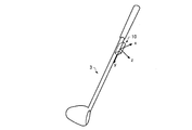
センサーユニット10は、3軸の各軸方向に生じる加速度と3軸の各軸回りに生じる角速度を計測可能であり、ゴルフクラブ3(運動器具の一例)に装着される。   The sensor unit 10 can measure the acceleration generated in each of the three axes and the angular velocity generated around each of the three axes, and is attached to the golf club 3 (an example of an exercise device).

本実施形態では、図2に示すように、センサーユニット10は、3つの検出軸(x軸,y軸,z軸)のうちの1軸、例えばy軸をシャフトの長軸方向に合わせて、ゴルフクラブ3のシャフトの一部に取り付けられる。望ましくは、センサーユニット10は、打球時の衝撃が伝わりにくく、スイング時に遠心力がかからないグリップに近い位置に取り付けられる。シャフトは、ゴルフクラブ3のヘッドを除いた柄の部分であり、グリップも含まれる。ただし、センサーユニット10は、ユーザー2の部位(例えば、手やグローブなど)に取り付けられてもよいし、腕時計などのアクセサリーに取り付けられてもよい。   In the present embodiment, as shown in FIG. 2, the sensor unit 10 has one of three detection axes (x-axis, y-axis, z-axis), for example, the y-axis aligned with the long axis direction of the shaft. It is attached to a part of the shaft of the golf club 3. Desirably, the sensor unit 10 is attached to a position close to a grip that is difficult to transmit an impact at the time of hitting and is not subjected to a centrifugal force during a swing. The shaft is a portion of the handle excluding the head of the golf club 3 and includes a grip. However, the sensor unit 10 may be attached to a part of the user 2 (for example, a hand or a glove), or may be attached to an accessory such as a wristwatch.

ユーザー2は、あらかじめ決められた手順に従って、ゴルフボール4を打球するスイング動作を行う。図3は、ユーザー2が行う動作の手順を示す図である。図3に示すように、ユーザー2は、まず、傾き判定装置20を介してユーザー2の身体情報とユーザー2が使用するゴルフクラブ3に関する情報(ゴルフクラブ情報)などの入力操作を行う(S1)。身体情報は、ユーザー2の身長、腕の長さ及び脚の長さの少なくとも1つの情報を含み、さらに性別の情報やその他の情報を含んでもよい。ゴルフクラブ情報は、ゴルフクラブ3の長さ(クラブ長)の情報およびゴルフクラブ3の種類(番手)の少なくとも一方の情報を含む。次に、ユーザー2は、傾き判定装置20を介して計測開始操作(センサーユニット10に計測を開始させるための操作)を行う(S2)。次に、ユーザー2は、傾き判定装置20からアドレス姿勢(運動開始前の基本姿勢)をとるように指示する通知(例えば音声による通知)を受けた後(S3のY)、ゴルフクラブ3のシャフトの長軸がターゲットライン(打球の目標方向)に対して垂直となるようにアドレスの姿勢をとり、静止する(S4)。次に、ユーザー2は、傾き判定装置20からスイングを許可する通知(例えば音声による通知)を受けた後(S5のY)、スイング動作を行い、ゴルフボール4を打球する(S6)。   The user 2 performs a swing motion of hitting the golf ball 4 according to a predetermined procedure. FIG. 3 is a diagram illustrating a procedure of an operation performed by the user 2. As shown in FIG. 3, the user 2 first performs an input operation such as body information of the user 2 and information (golf club information) regarding the golf club 3 used by the user 2 via the tilt determination device 20 (S1). . The body information includes at least one piece of information on the height, arm length, and leg length of the user 2, and may further include sex information and other information. The golf club information includes information on the length of the golf club 3 (club length) and information on at least one of the types (counts) of the golf club 3. Next, the user 2 performs a measurement start operation (operation for causing the sensor unit 10 to start measurement) via the inclination determination device 20 (S2). Next, the user 2 receives a notification (for example, a voice notification) instructing to take an address posture (basic posture before starting exercise) from the tilt determination device 20 (Y in S3), and then the shaft of the golf club 3 The position of the address is taken so that the long axis is perpendicular to the target line (the target direction of the hit ball), and it stops (S4). Next, after receiving notification (for example, notification by voice) that permits the swing from the tilt determination device 20 (Y in S5), the user 2 performs a swing motion and hits the golf ball 4 (S6).

図4(A)は、傾き判定装置20の表示部に表示される身体情報の入力画面の一例を示す図であり、図4(B)は、傾き判定装置20の表示部に表示されるゴルフクラブ情報の入力画面の一例を示す図である。ユーザー2は、図3のS1において、図4(A)に示す入力画面上で身長、性別、年齢、国籍などの身体情報を入力し、図4(B)に示す入力画面上でクラブ長、番手などのゴルフクラブ情報を入力する。なお、身体情報に含まれる情報は、これに限られず、例えば、身体情報は、身長に代えて又は身長とともに腕の長さ及び脚の長さの少なくとも一方の情報を含んでもよい。同様に、ゴルフクラブ情報に含まれる情報は、これに限られず、例えば、ゴルフクラブ情報は、クラブ長と番手のいずれか一方の情報を含まなくてもよいし、他の情報を含んでもよい。   FIG. 4A is a diagram illustrating an example of an input screen for physical information displayed on the display unit of the tilt determination apparatus 20, and FIG. 4B is a golf displayed on the display unit of the tilt determination apparatus 20. It is a figure which shows an example of the input screen of club information. In S1 of FIG. 3, the user 2 inputs physical information such as height, gender, age, nationality, etc. on the input screen shown in FIG. 4A, and the club head on the input screen shown in FIG. Enter golf club information such as the count. The information included in the body information is not limited to this. For example, the body information may include information on at least one of the length of the arm and the length of the leg instead of the height or together with the height. Similarly, the information included in the golf club information is not limited to this. For example, the golf club information may not include information on either the club head or the count, or may include other information.

ユーザー2が図3のS2の計測開始操作を行うと、センサーユニット10は、所定周期
(例えば1ms)で3軸加速度と3軸角速度を計測し、計測したデータを順次、傾き判定装置20に送信する。センサーユニット10と傾き判定装置20との間の通信は、無線通信でもよいし、有線通信でもよい。
When the user 2 performs the measurement start operation of S2 in FIG. 3, the sensor unit 10 measures the triaxial acceleration and the triaxial angular velocity at a predetermined cycle (for example, 1 ms), and sequentially transmits the measured data to the inclination determination device 20. To do. Communication between the sensor unit 10 and the inclination determination device 20 may be wireless communication or wired communication.

傾き判定装置20は、センサーユニット10が計測したデータ(慣性センサーの出力信号の一例)を用いて、ユーザー2の運動開始前のゴルフクラブ3の傾きを算出し、運動器具の傾きが、図3のS1で入力されたゴルフクラブ情報と身体情報とに基づいて決定される基準範囲に含まれるか否かを判定する。そして、傾き判定装置20は、運動開始前のゴルフクラブ3の傾きが基準範囲に含まれると判定した場合に、図3のS5に示したスイング開始の許可(運動の開始の許可の一例)をユーザー2に通知し、その後、ユーザー2がゴルフクラブ3を用いて打球したスイング運動を解析する。例えば、傾き判定装置20は、センサーユニット10が計測した計測データを用いて、スイングにおけるゴルフクラブ3のヘッドやグリップエンドの軌跡情報を生成する。   The inclination determination device 20 calculates the inclination of the golf club 3 before the user 2 starts exercising using the data measured by the sensor unit 10 (an example of the output signal of the inertial sensor). It is determined whether it is included in the reference range determined based on the golf club information and physical information input in S1. When the inclination determination device 20 determines that the inclination of the golf club 3 before the start of exercise is included in the reference range, the swing start permission (an example of permission to start the exercise) shown in S5 of FIG. The user 2 is notified, and then the swing motion that the user 2 hits using the golf club 3 is analyzed. For example, the tilt determination device 20 uses the measurement data measured by the sensor unit 10 to generate trajectory information of the golf club 3 head and grip end in a swing.

特に、本実施形態では、傾き判定装置20は、ユーザー2の運動開始前のゴルフクラブ3の傾きが基準範囲に含まれると判定した場合に、ゴルフクラブ3の傾きが基準範囲に含まれている時のセンサーユニット10の計測データを用いて、ゴルフクラブ3の長軸方向に沿った第1軸を特定し、この第1軸を基にユーザー2の静止時(アドレス時)における第1仮想平面であるシャフトプレーンを特定する。また、傾き判定装置20は、ユーザー2の運動開始前のゴルフクラブ3の傾きが基準範囲に含まれると判定した場合に、ゴルフクラブ3の傾きが基準範囲に含まれている時のセンサーユニット10の計測データを用いて、ユーザー2の頭部と胸部の間の所定位置と打撃位置とを結ぶ第2軸を特定し、この第2軸を基にユーザー2の静止時(アドレス時)における第2仮想平面であるホーガンプレーンを特定する。そして、傾き判定装置20は、ユーザー2のスイング開始から打球時までのゴルフクラブ3の軌跡がシャフトプレーンとホーガンプレーンとの間のVゾーンと呼ばれる空間に含まれるか否かを判定する。また、傾き判定装置20は、ユーザー2のスイングにおけるゴルフクラブ3の軌跡、シャフトプレーン及びホーガンプレーンを含む画像データを生成し、当該画像データに応じた画像を表示部(ディスプレイ)に表示させる。傾き判定装置20は、例えば、スマートフォンなどの携帯機器やパーソナルコンピューター(PC)であってもよい。   In particular, in this embodiment, when the inclination determination device 20 determines that the inclination of the golf club 3 before the user 2 starts exercising is included in the reference range, the inclination of the golf club 3 is included in the reference range. Using the measurement data of the sensor unit 10 at the time, the first axis along the long axis direction of the golf club 3 is specified, and the first virtual plane when the user 2 is stationary (at the time of addressing) based on the first axis Identify the shaft plane that is In addition, when the inclination determination device 20 determines that the inclination of the golf club 3 before the start of exercise of the user 2 is included in the reference range, the sensor unit 10 when the inclination of the golf club 3 is included in the reference range. The second axis that connects the predetermined position between the head and chest of the user 2 and the striking position is identified using the measurement data of the user 2, and the second axis when the user 2 is stationary (at the time of addressing) is determined based on the second axis. 2 Identify the Hogan plane, which is a virtual plane. And the inclination determination apparatus 20 determines whether the locus | trajectory of the golf club 3 from the user's 2 swing start to the time of hitting is contained in the space called the V zone between a shaft plane and a Hogan plane. In addition, the tilt determination device 20 generates image data including the locus of the golf club 3 in the swing of the user 2, the shaft plane, and the Hogan plane, and displays an image corresponding to the image data on a display unit (display). The inclination determination device 20 may be, for example, a portable device such as a smartphone or a personal computer (PC).

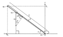
図5は、本実施形態におけるユーザー2のアドレス時のシャフトプレーン及びホーガンプレーン示す図である。本実施形態では、打球の目標方向を示すターゲットラインをX軸、X軸に垂直な水平面上の軸をY軸、鉛直上方向(重力加速度の方向と逆方向)をZ軸とするXYZ座標系(グローバル座標系)を定義し、図5にはX軸、Y軸、Z軸が表記されている。   FIG. 5 is a diagram showing a shaft plane and a Hogan plane at the time of the address of the user 2 in the present embodiment. In the present embodiment, an XYZ coordinate system in which the target line indicating the target direction of the hit ball is the X axis, the axis on the horizontal plane perpendicular to the X axis is the Y axis, and the vertical direction (the direction opposite to the direction of gravitational acceleration) is the Z axis. (Global coordinate system) is defined, and the X axis, the Y axis, and the Z axis are shown in FIG.

図5に示すように、本実施形態では、ユーザー2のアドレス時のシャフトプレーン30はゴルフクラブ3のシャフトの長軸方向に沿った第1軸としての第1線分51と、打球の目標方向を表す第3軸としての第3線分52と、を含み、T1,T2,S1,S2を4つの頂点とする仮想平面である。本実施形態では、ゴルフクラブ3のヘッド(打撃部)の位置61をXYZ座標系の原点O(0,0,0)とし、第1線分51は、ゴルフクラブ3のヘッドの位置61(原点O)とグリップエンドの位置62とを結ぶ線分である。また、第3線分52は、X軸上のT1,T2を両端として原点Oを中点とする長さTLの線分である。ユーザー2がアドレス時に図3のS4の動作を行うことでゴルフクラブ3のシャフトがターゲットライン(X軸)に対して垂直となるので、第3線分52は、ゴルフクラブ3のシャフトの長軸方向と直交する線分、すなわち第1線分51と直交する線分である。XYZ座標系における4つの頂点T1,T2,S1,S2の各座標を算出することによりシャフトプレーン30が特定される。T1,T2,S1,S2の各座標の算出方法については後述する。   As shown in FIG. 5, in this embodiment, the shaft plane 30 at the time of the address of the user 2 includes a first line segment 51 as a first axis along the major axis direction of the shaft of the golf club 3 and the target direction of the hit ball And a third line segment 52 as a third axis that represents the virtual plane with T1, T2, S1, and S2 as four vertices. In the present embodiment, the position 61 of the head (striking part) of the golf club 3 is the origin O (0, 0, 0) of the XYZ coordinate system, and the first line segment 51 is the position 61 (origin of the golf club 3) This is a line segment connecting O) and the grip end position 62. The third line segment 52 is a line segment having a length TL with T1 and T2 on the X axis as both ends and the origin O as a midpoint. When the user 2 performs the operation of S4 in FIG. 3 at the time of addressing, the shaft of the golf club 3 becomes perpendicular to the target line (X axis), so the third line segment 52 is the major axis of the shaft of the golf club 3 This is a line segment orthogonal to the direction, that is, a line segment orthogonal to the first line segment 51. The shaft plane 30 is specified by calculating the coordinates of the four vertices T1, T2, S1, and S2 in the XYZ coordinate system. A method for calculating the coordinates of T1, T2, S1, and S2 will be described later.

また、図5に示すように、本実施形態では、ホーガンプレーン40は、第3線分52と、第2軸としての第2線分53と、を含み、T1,T2,H1,H2を4つの頂点とする仮想平面である。本実施形態では、第2線分53は、ユーザー2の両肩を結ぶ線分上の所定位置63(例えば、首の付け根の位置や左右いずれかの肩の位置など)とゴルフクラブ3のヘッド(打撃部)の位置62(打撃位置の一例)とを結ぶ線分である。ただし、第2線分53は、所定位置63とゴルフボール4の位置(打撃位置の一例)とを結ぶ線分であってもよい。XYZ座標系における4つの頂点T1,T2,H1,H2の各座標を算出することによりホーガンプレーン40が特定される。T1,T2,H1,H2の各座標の算出方法については後述する。   As shown in FIG. 5, in the present embodiment, the Hogan plane 40 includes a third line segment 52 and a second line segment 53 as the second axis, and T1, T2, H1, and H2 are set to four. A virtual plane with two vertices. In the present embodiment, the second line segment 53 is a predetermined position 63 (for example, the position of the base of the neck or the position of one of the left and right shoulders) on the line segment connecting both shoulders of the user 2 and the head of the golf club 3. This is a line segment that connects the position 62 (an example of the striking position) of the (striking part). However, the second line segment 53 may be a line segment connecting the predetermined position 63 and the position of the golf ball 4 (an example of a hitting position). The Hogan plane 40 is specified by calculating the coordinates of the four vertices T1, T2, H1, and H2 in the XYZ coordinate system. A method for calculating the coordinates of T1, T2, H1, and H2 will be described later.

1−2.傾き判定システムの構成
図6は、本実施形態の傾き判定システム1の構成例(センサーユニット10及び傾き判定装置20の構成例)を示す図である。図6に示すように、本実施形態では、センサーユニット10は、加速度センサー12、角速度センサー14、信号処理部16及び通信部18を含んで構成されている。
1-2. Configuration of Inclination Determination System FIG. 6 is a diagram illustrating a configuration example (configuration example of the sensor unit 10 and the inclination determination device 20) of the inclination determination system 1 of the present embodiment. As shown in FIG. 6, in this embodiment, the sensor unit 10 includes an acceleration sensor 12, an angular velocity sensor 14, a signal processing unit 16, and a communication unit 18.

加速度センサー12(慣性センサーの一例)は、互いに交差する(理想的には直交する)3軸方向の各々に生じる加速度を計測し、計測した3軸加速度の大きさ及び向きに応じたデジタル信号(加速度データ)を出力する。   The acceleration sensor 12 (an example of an inertial sensor) measures acceleration generated in each of three axis directions that intersect each other (ideally orthogonal), and a digital signal (in accordance with the magnitude and direction of the measured three axis acceleration) Output acceleration data).

角速度センサー14(慣性センサーの一例)は、互いに交差する(理想的には直交する)3軸の各々の軸回りに生じる角速度を計測し、計測した3軸角速度の大きさ及び向きに応じたデジタル信号(角速度データ)を出力する。   The angular velocity sensor 14 (an example of an inertial sensor) measures an angular velocity generated around each of three axes that intersect each other (ideally orthogonally), and digital corresponding to the magnitude and direction of the measured three-axis angular velocity. A signal (angular velocity data) is output.

信号処理部16は、加速度センサー12と角速度センサー14から、それぞれ加速度データと角速度データを受け取って時刻情報を付して不図示の記憶部に記憶し、記憶した計測データ(加速度データと角速度データ)に時刻情報を付して通信用のフォーマットに合わせたパケットデータを生成し、通信部18に出力する。   The signal processing unit 16 receives acceleration data and angular velocity data from the acceleration sensor 12 and the angular velocity sensor 14, respectively, attaches time information to the storage unit (not shown), and stores the measurement data (acceleration data and angular velocity data). Is attached with time information to generate packet data in accordance with the communication format, and outputs the packet data to the communication unit 18.

加速度センサー12及び角速度センサー14は、それぞれ3軸が、センサーユニット10に対して定義される直交座標系(センサー座標系)の3軸(x軸、y軸、z軸)と一致するようにセンサーユニット10に取り付けられるのが理想的だが、実際には取り付け角の誤差が生じる。そこで、信号処理部16は、取り付け角誤差に応じてあらかじめ算出された補正パラメーターを用いて、加速度データ及び角速度データをxyz座標系のデータに変換する処理を行う。   The acceleration sensor 12 and the angular velocity sensor 14 each have three axes that coincide with the three axes (x axis, y axis, z axis) of the orthogonal coordinate system (sensor coordinate system) defined for the sensor unit 10. Although it is ideal to be attached to the unit 10, an error in the attachment angle actually occurs. Therefore, the signal processing unit 16 performs a process of converting the acceleration data and the angular velocity data into data in the xyz coordinate system using a correction parameter calculated in advance according to the attachment angle error.

さらに、信号処理部16は、加速度センサー12及び角速度センサー14の温度補正処理を行ってもよい。あるいは、加速度センサー12及び角速度センサー14に温度補正の機能が組み込まれていてもよい。   Further, the signal processing unit 16 may perform temperature correction processing of the acceleration sensor 12 and the angular velocity sensor 14. Alternatively, a temperature correction function may be incorporated in the acceleration sensor 12 and the angular velocity sensor 14.

なお、加速度センサー12と角速度センサー14は、アナログ信号を出力するものであってもよく、この場合は、信号処理部16が、加速度センサー12の出力信号と角速度センサー14の出力信号をそれぞれA/D変換して計測データ(加速度データと角速度データ)を生成し、これらを用いて通信用のパケットデータを生成すればよい。   The acceleration sensor 12 and the angular velocity sensor 14 may output analog signals. In this case, the signal processing unit 16 converts the output signal of the acceleration sensor 12 and the output signal of the angular velocity sensor 14 to A / Measurement data (acceleration data and angular velocity data) is generated by D conversion, and packet data for communication may be generated using these.

通信部18は、信号処理部16から受け取ったパケットデータを傾き判定装置20に送信する処理や、傾き判定装置20から制御コマンドを受信して信号処理部16に送る処理等を行う。信号処理部16は、制御コマンドに応じた各種処理を行う。   The communication unit 18 performs processing for transmitting the packet data received from the signal processing unit 16 to the inclination determination device 20, processing for receiving a control command from the inclination determination device 20 and sending the control command to the signal processing unit 16, and the like. The signal processing unit 16 performs various processes according to the control command.

傾き判定装置20(運動解析装置)は、処理部21、通信部22、操作部23、記憶部24、表示部25、音出力部26を含んで構成されている。   The inclination determination device 20 (motion analysis device) includes a processing unit 21, a communication unit 22, an operation unit 23, a storage unit 24, a display unit 25, and a sound output unit 26.

通信部22は、センサーユニット10から送信されたパケットデータを受信し、処理部21に送る処理や、処理部21からの制御コマンドをセンサーユニット10に送信する処理等を行う。   The communication unit 22 receives the packet data transmitted from the sensor unit 10 and performs processing for sending the packet data to the processing unit 21, processing for transmitting a control command from the processing unit 21 to the sensor unit 10, and the like.

操作部23は、ユーザー2からの操作データを取得し、処理部21に送る処理を行う。操作部23は、例えば、タッチパネル型ディスプレイ、ボタン、キー、マイクなどであってもよい。   The operation unit 23 performs a process of acquiring operation data from the user 2 and sending it to the processing unit 21. The operation unit 23 may be, for example, a touch panel display, a button, a key, a microphone, or the like.

記憶部24は、例えば、ROM(Read Only Memory)やフラッシュROM、RAM(Random Access Memory)等の各種ICメモリーやハードディスクやメモリーカードなどの記録媒体等により構成される。   The storage unit 24 includes, for example, various IC memories such as a ROM (Read Only Memory), a flash ROM, and a RAM (Random Access Memory), a recording medium such as a hard disk and a memory card, and the like.

記憶部24は、処理部21が各種の計算処理や制御処理を行うためのプログラムや、アプリケーション機能を実現するための各種プログラムやデータ等を記憶している。特に、本実施形態では、記憶部24には、処理部21によって読み出され、傾き判定処理(運動解析処理)を実行するための傾き判定プログラム240(運動解析プログラム)が記憶されている。傾き判定プログラム240はあらかじめ不揮発性の記録媒体に記憶されていてもよいし、処理部21がネットワークを介してサーバーから傾き判定プログラム240を受信して記憶部24に記憶させてもよい。   The storage unit 24 stores programs for the processing unit 21 to perform various calculation processes and control processes, various programs and data for realizing application functions, and the like. In particular, in the present embodiment, the storage unit 24 stores an inclination determination program 240 (motion analysis program) that is read by the processing unit 21 and executes an inclination determination process (motion analysis process). The inclination determination program 240 may be stored in advance in a non-volatile recording medium, or the processing unit 21 may receive the inclination determination program 240 from the server via the network and store it in the storage unit 24.

また、本実施形態では、記憶部24には、ゴルフクラブ情報242、身体情報244、センサー装着位置情報246及び基準範囲情報248が記憶される。例えば、ユーザー2が、操作部23を操作して、図4(B)の入力画面から、使用するゴルフクラブ3のゴルフクラブ情報を入力し、入力されたゴルフクラブ情報をゴルフクラブ情報242としてもよい。あるいは、ユーザー2が、図3のS1において、ゴルフクラブ3の型番を入力(あるいは、型番リストから選択)し、記憶部24にあらかじめ記憶されている型番毎の仕様情報(例えば、シャフトの長さ、重心の位置、ライ角、フェース角、ロフト角等の情報など)のうち、入力された型番の仕様情報をゴルフクラブ情報242としてもよい。また、例えば、ユーザー2が、操作部23を操作して、図4(A)の入力画面から、身体情報を入力し、入力された身体情報を身体情報244としてもよい。また、例えば、図3のS1において、ユーザー2が操作部23を操作してセンサーユニット10の装着位置とゴルフクラブ3のグリップとの間の距離を入力し、入力された距離の情報をセンサー装着位置情報246としてもよい。あるいは、センサーユニット10を決められた所定位置(例えば、グリップから20cmの距離など)に装着するものとして、当該所定位置の情報がセンサー装着位置情報246としてあらかじめ記憶されていてもよい。   In the present embodiment, the storage unit 24 stores golf club information 242, body information 244, sensor mounting position information 246, and reference range information 248. For example, the user 2 operates the operation unit 23 to input the golf club information of the golf club 3 to be used from the input screen of FIG. 4B, and the input golf club information is used as the golf club information 242. Good. Alternatively, the user 2 inputs the model number of the golf club 3 in S1 of FIG. 3 (or selects from the model number list), and the specification information for each model number stored in the storage unit 24 in advance (for example, the length of the shaft) Of the center of gravity, lie angle, face angle, loft angle, etc.) may be used as the golf club information 242. Further, for example, the user 2 may operate the operation unit 23 to input physical information from the input screen in FIG. 4A, and the input physical information may be used as the physical information 244. Further, for example, in S1 of FIG. 3, the user 2 operates the operation unit 23 to input the distance between the mounting position of the sensor unit 10 and the grip of the golf club 3, and the information on the input distance is mounted on the sensor. The position information 246 may be used. Alternatively, information on the predetermined position may be stored in advance as sensor mounting position information 246, assuming that the sensor unit 10 is mounted at a predetermined position (for example, a distance of 20 cm from the grip).

基準範囲情報248は、ユーザーのアドレス時のゴルフクラブの傾斜角(水平面(XY平面)あるいは鉛直面(XZ平面)に対する傾き)として適正な範囲(基準範囲)を規定する情報であり、例えば、ユーザーの身長と当該ユーザーが使用するゴルフクラブのクラブ長(シャフトの長さ)との組み合わせに応じて各々の基準範囲を規定するテーブル情報を含んでもよい。   The reference range information 248 is information that defines an appropriate range (reference range) as the golf club inclination angle (tilt with respect to the horizontal plane (XY plane) or the vertical plane (XZ plane)) at the user's address. Table information defining each reference range according to the combination of the height of the golf club and the club length (shaft length) of the golf club used by the user.

図7は、基準範囲情報248に含まれる、ユーザーのアドレス時におけるゴルフクラブの傾斜角θ(水平面(XY平面)に対する傾き)の基準範囲の上限値θMAXを規定するテーブル情報(ルックアップテーブル)の一例を示す図である。図7において、列方向は身長あるいは股下高(股下の長さ)(単位:cm)であり、行方向はクラブ長(単位:cm)である。本実施形態では、ゴルフクラブのグリップエンドの地面からの高さが股下高
(ほぼ脚の長さ)と一致する時の傾斜角θを上限値θMAXとしている。そして、股下高は、身長を変数として(より正確には、性別、年齢、国籍なども変数として)、統計データに基づく相関式によって計算され、クラブ長をa、股下高をbとすると、上限値θMAXは、arcsin(b/a)で計算される。図7のルックアップテーブルでは、例えば、図4(A)に示したように、身長が170cm(かつ、男性、36歳、日本人)のユーザー2は、股下高が77.049cmと計算され、図4(B)に示したように、クラブ長が115cmのゴルフクラブ3を使用する場合、上限値θMAXは42.1°であることが規定されている。なお、クラブ長aが股下高bよりも小さくなるような(上限値θMAXが90°を超える)アドレス姿勢は考えられないので、図7の例では、クラブ長aが股下高bよりも小さくなる組み合わせでの上限値θMAXを90°としている。
FIG. 7 is table information (lookup table) that defines the upper limit value θ MAX of the reference range of the golf club inclination angle θ (inclination with respect to the horizontal plane (XY plane)) included in the reference range information 248 at the user's address. It is a figure which shows an example. In FIG. 7, the column direction is height or crotch height (inseam length) (unit: cm), and the row direction is club length (unit: cm). In the present embodiment, the inclination angle θ when the height of the grip end of the golf club from the ground coincides with the crotch height (substantially the length of the legs) is set as the upper limit value θ MAX . The inseam height is calculated by a correlation formula based on statistical data using height as a variable (more accurately, gender, age, nationality, etc.). If the club length is a and the inseam is b, The value θ MAX is calculated as arcsin (b / a). In the look-up table in FIG. 7, for example, as shown in FIG. 4A, the user 2 who is 170 cm tall (and male, 36 years old, Japanese) is calculated to have an inseam height of 77.049 cm. As shown in FIG. 4B, when the golf club 3 having a club length of 115 cm is used, the upper limit value θ MAX is defined to be 42.1 °. It should be noted that an address posture in which the club length a is smaller than the crotch height b (upper limit value θ MAX exceeds 90 °) is not conceivable. Therefore, in the example of FIG. 7, the club length a is smaller than the crotch height b. In this combination, the upper limit value θ MAX is 90 °.

図8は、基準範囲情報248に含まれる、ユーザーのアドレス時におけるゴルフクラブの傾斜角θ(水平面(XY平面)に対する傾き)の基準範囲の下限値θMINを規定するテーブル情報(ルックアップテーブル)の一例を示す図である。図8において、列方向は身長あるいは膝下高(膝下の長さ)(単位:cm)であり、行方向はクラブ長(単位:cm)である。本実施形態では、ゴルフクラブのグリップエンドの地面からの高さが膝下高と一致する時の傾斜角θを下限値θMINとしている。そして、膝下高は、身長を変数として(より正確には、性別、年齢、国籍なども変数として)、統計データに基づく相関式によって計算され、クラブ長をa、膝下高をcとすると、下限値θMINは、arcsin(c/a)で計算される。図8のルックアップテーブルでは、例えば、図4(A)に示したように、身長が170cm(かつ、男性、36歳、日本人)のユーザー2は、膝下高が46.491cmと計算され、図4(B)に示したように、クラブ長が115cmのゴルフクラブ3を使用する場合、下限値θMINは23.8°であることが規定されている。 FIG. 8 is table information (lookup table) that defines the lower limit value θ MIN of the reference range of the golf club inclination angle θ (inclination with respect to the horizontal plane (XY plane)) at the time of the user's address, which is included in the reference range information 248. It is a figure which shows an example. In FIG. 8, the column direction is the height or the knee height (the length under the knee) (unit: cm), and the row direction is the club length (unit: cm). In the present embodiment, the inclination angle θ when the height of the grip end of the golf club from the ground coincides with the height below the knee is set to the lower limit value θ MIN . The knee height is calculated by a correlation formula based on statistical data with height as a variable (more precisely, gender, age, nationality, etc.). When the club length is a and the knee height is c, The value θ MIN is calculated as arcsin (c / a). In the lookup table of FIG. 8, for example, as shown in FIG. 4A, the user 2 whose height is 170 cm (and male, 36 years old, Japanese) is calculated to have a knee height of 46.491 cm, As shown in FIG. 4B, when the golf club 3 having a club length of 115 cm is used, the lower limit value θ MIN is specified to be 23.8 °.

また、記憶部24は、処理部21の作業領域として用いられ、操作部23から入力されたデータ、処理部21が各種プログラムに従って実行した演算結果等を一時的に記憶する。さらに、記憶部24は、処理部21の処理により生成されたデータのうち、長期的な保存が必要なデータを記憶してもよい。   The storage unit 24 is used as a work area of the processing unit 21, and temporarily stores data input from the operation unit 23, calculation results executed by the processing unit 21 according to various programs, and the like. Furthermore, the memory | storage part 24 may memorize | store the data which require long-term preservation | save among the data produced | generated by the process of the process part 21. FIG.

表示部25は、処理部21の処理結果を文字、グラフ、表、アニメーション、その他の画像として表示するものである。表示部25は、例えば、CRT、LCD、タッチパネル型ディスプレイ、HMD(ヘッドマウントディスプレイ)などであってもよい。なお、1つのタッチパネル型ディスプレイで操作部23と表示部25の機能を実現するようにしてもよい。   The display unit 25 displays the processing results of the processing unit 21 as characters, graphs, tables, animations, and other images. The display unit 25 may be, for example, a CRT, LCD, touch panel display, HMD (head mounted display), or the like. In addition, you may make it implement | achieve the function of the operation part 23 and the display part 25 with one touchscreen type display.

音出力部26は、処理部21の処理結果を音声やブザー音等の音として出力するものである。音出力部26は、例えば、スピーカーやブザーなどであってもよい。   The sound output unit 26 outputs the processing result of the processing unit 21 as sound such as sound or buzzer sound. The sound output unit 26 may be, for example, a speaker or a buzzer.

処理部21は、各種プログラムに従って、センサーユニット10に制御コマンドを送信する処理や、センサーユニット10から通信部22を介して受信したデータに対する各種の計算処理や、その他の各種の制御処理を行う。特に、本実施形態では、処理部21は、傾き判定プログラム240を実行することにより、データ取得部210、傾き算出部211、判定部212、第1特定部213、第2特定部214、運動解析部215、画像データ生成部216、記憶処理部217、表示処理部218及び音出力処理部219として機能する。   The processing unit 21 performs processing for transmitting a control command to the sensor unit 10 according to various programs, various calculation processing for data received from the sensor unit 10 via the communication unit 22, and various other control processing. In particular, in the present embodiment, the processing unit 21 executes the inclination determination program 240 to thereby obtain a data acquisition unit 210, an inclination calculation unit 211, a determination unit 212, a first specifying unit 213, a second specifying unit 214, and a motion analysis. Functions as a unit 215, an image data generation unit 216, a storage processing unit 217, a display processing unit 218, and a sound output processing unit 219.

データ取得部210は、通信部22がセンサーユニット10から受信したパケットデータを受け取り、受け取ったパケットデータから時刻情報及び計測データを取得し、記憶処理部217に送る処理を行う。   The data acquisition unit 210 receives the packet data received from the sensor unit 10 by the communication unit 22, acquires time information and measurement data from the received packet data, and performs processing to send to the storage processing unit 217.

記憶処理部217は、データ取得部210から時刻情報と計測データを受け取り、これらを対応づけて記憶部24に記憶させる処理を行う。   The storage processing unit 217 receives time information and measurement data from the data acquisition unit 210, and performs a process of associating them with each other and storing them in the storage unit 24.

傾き算出部211は、センサーユニット10が出力する計測データを用いて、ユーザー2のスイング開始前のゴルフクラブ3の傾きを算出する処理を行う。本実施形態では、ユーザー2が図3のS4の動作を行い、傾き算出部211は、加速度センサー12が計測した加速度データの変化量が所定時間継続して閾値を超えない場合に、当該所定時間内の加速度データを用いて、ゴルフクラブ3のシャフトの傾斜角θを計算する。   The inclination calculation unit 211 performs a process of calculating the inclination of the golf club 3 before the user 2 starts swinging using the measurement data output from the sensor unit 10. In the present embodiment, the user 2 performs the operation of S4 in FIG. 3, and the inclination calculation unit 211 performs the predetermined time when the change amount of the acceleration data measured by the acceleration sensor 12 does not exceed the threshold for a predetermined time. The inclination angle θ of the shaft of the golf club 3 is calculated using the acceleration data inside.

判定部212は、傾き算出部211が算出したゴルフクラブ3の傾き(傾斜角θ)が、ゴルフクラブ情報242と身体情報244とに基づいて決定される基準範囲に含まれるか否かを判定する。具体的には、判定部212は、基準範囲情報248(例えば、図7のルックアップテーブル及び図8のルックアップテーブル)を参照し、ゴルフクラブ情報242に含まれるクラブ長の情報と身体情報244に含まれる身長などの情報に応じた、ゴルフクラブ3の傾斜角θの基準範囲を決定し、傾き算出部211が算出したゴルフクラブ3の傾斜角θが当該基準範囲に含まれるか否かを判定する。例えば、ユーザー2が図3のS1において、図4(A)に示す身体情報と図4(B)に示すゴルフクラブ情報を入力した場合、判定部212は、図7のルックアップテーブル及び図8のルックアップテーブルに基づき、ゴルフクラブ3の傾斜角θの基準範囲を23.8°以上42.1°以下の範囲に決定し、傾き算出部211が算出したゴルフクラブ3の傾斜角θが23.8°以上42.1°以下の範囲に含まれるか否かを判定する。   The determination unit 212 determines whether or not the inclination (inclination angle θ) of the golf club 3 calculated by the inclination calculation unit 211 is included in a reference range determined based on the golf club information 242 and the body information 244. . Specifically, the determination unit 212 refers to the reference range information 248 (for example, the look-up table in FIG. 7 and the look-up table in FIG. 8), and information on the club length and physical information 244 included in the golf club information 242. A reference range of the inclination angle θ of the golf club 3 is determined according to information such as the height included in the golf club 3, and whether or not the inclination angle θ of the golf club 3 calculated by the inclination calculation unit 211 is included in the reference range. judge. For example, when the user 2 inputs the physical information shown in FIG. 4A and the golf club information shown in FIG. 4B in S1 of FIG. 3, the determination unit 212 displays the lookup table of FIG. Is set to a range of 23.8 ° or more and 42.1 ° or less, and the inclination angle θ of the golf club 3 calculated by the inclination calculation unit 211 is 23. It is determined whether it falls within the range of 8 ° or more and 42.1 ° or less.

第1特定部213は、判定部212によってゴルフクラブ3の傾き(傾斜角θ)が基準範囲に含まれると判定された場合に、センサーユニット10が出力し、記憶部24に記憶された計測データを用いて、ゴルフクラブ3の長軸方向に沿った第1軸である第1線分51(図5参照)を特定する処理を行う。具体的には、第1特定部213は、ゴルフクラブ3の傾斜角θが基準範囲に含まれている時の計測データを用いて、第1線分51を特定する。例えば、第1特定部213は、当該計測データを用いて、ゴルフクラブ3のシャフトの傾斜角を計算し、計算した傾斜角とゴルフクラブ情報242に含まれるゴルフクラブ3の長さ(シャフトの長さ)の情報とを用いて、ゴルフクラブ3のグリップエンドの位置62の座標を計算し、ゴルフクラブ3のヘッド(打撃部)の位置61(原点O)とグリップエンドの位置62とを結ぶ線分を第1線分51として特定してもよい。   When the determination unit 212 determines that the inclination (inclination angle θ) of the golf club 3 is included in the reference range, the first specifying unit 213 outputs the measurement data stored in the storage unit 24 and output from the sensor unit 10. Is used to specify the first line segment 51 (see FIG. 5) which is the first axis along the long axis direction of the golf club 3. Specifically, the first specifying unit 213 specifies the first line segment 51 using measurement data when the inclination angle θ of the golf club 3 is included in the reference range. For example, the first specifying unit 213 calculates the inclination angle of the shaft of the golf club 3 using the measurement data, and calculates the calculated inclination angle and the length of the golf club 3 included in the golf club information 242 (the length of the shaft). )) Is used to calculate the coordinates of the grip end position 62 of the golf club 3, and a line connecting the position 61 (origin O) of the head (striking part) of the golf club 3 and the position 62 of the grip end. The minute may be specified as the first line segment 51.

さらに、第1特定部213は、第1線分51と、打球の目標方向を表す第3線分52と、を含むシャフトプレーン(第1仮想平面)30(図5参照)を特定する処理を行う。第1特定部213は、第1線分51の長さと身体情報244に基づくユーザー2の腕の長さとを用いて、シャフトプレーン30の幅を計算してもよい。   Furthermore, the 1st specific | specification part 213 specifies the shaft plane (1st virtual plane) 30 (refer FIG. 5) containing the 1st line segment 51 and the 3rd line segment 52 showing the target direction of a hit ball. Do. The first specifying unit 213 may calculate the width of the shaft plane 30 using the length of the first line segment 51 and the length of the arm of the user 2 based on the body information 244.

第2特定部214は、判定部212によってゴルフクラブ3の傾きが基準範囲に含まれると判定された場合に、センサーユニット10が出力し、記憶部24に記憶された計測データを用いて、ユーザー2の頭部と胸部の間(例えば、両肩を結ぶ線分上)の所定位置63と打撃位置とを結ぶ第2軸である第2線分53(図5参照)を特定する処理を行う。具体的には、第2特定部214は、ゴルフクラブ3の傾きが基準範囲に含まれている時の計測データを用いて、第2線分53を特定する。例えば、第2特定部214は、当該計測データと身体情報244とを用いて、所定位置63を推定し、推定した所定位置63とゴルフクラブ3のヘッド(打撃部)の位置62(原点O)とを結ぶ線分を第2線分53として特定してもよい。例えば、第2特定部214は、第1特定部213が計算したグリップエンドの位置62の座標と、身体情報244に基づくユーザー2の腕の長さとを用いて、所定位置63を推定してもよい。あるいは、第2特定部214が、ゴルフクラブ3の傾きが
基準範囲に含まれている時の計測データを用いて、ゴルフクラブ3のグリップエンドの位置62の座標を計算してもよい。この場合は、第1特定部213は、第2特定部214が計算したグリップエンドの位置62の座標を用いて、第1線分51を特定してもよい。
The second specifying unit 214 uses the measurement data output from the sensor unit 10 and stored in the storage unit 24 when the determination unit 212 determines that the inclination of the golf club 3 is included in the reference range. The second line segment 53 (see FIG. 5) that is the second axis that connects the predetermined position 63 and the striking position between the head and the chest (for example, on the line segment that connects both shoulders) is performed. . Specifically, the second specifying unit 214 specifies the second line segment 53 using measurement data when the inclination of the golf club 3 is included in the reference range. For example, the second specifying unit 214 estimates the predetermined position 63 using the measurement data and the physical information 244, and the estimated predetermined position 63 and the position 62 (origin O) of the head (striking part) of the golf club 3. May be specified as the second line segment 53. For example, the second specifying unit 214 may estimate the predetermined position 63 using the coordinates of the grip end position 62 calculated by the first specifying unit 213 and the arm length of the user 2 based on the body information 244. Good. Alternatively, the second specifying unit 214 may calculate the coordinates of the grip end position 62 of the golf club 3 using measurement data when the inclination of the golf club 3 is included in the reference range. In this case, the first specifying unit 213 may specify the first line segment 51 using the coordinates of the grip end position 62 calculated by the second specifying unit 214.

さらに、第2特定部214は、第2線分53と、第3線分52と、を含むホーガンプレーン(第2仮想平面)40(図5参照)を特定する処理を行う。第2特定部214は、第1線分51の長さと身体情報244に基づくユーザー2の腕の長さとを用いて、ホーガンプレーン40の幅を計算してもよい。   Further, the second specifying unit 214 performs processing for specifying the Hogan plane (second virtual plane) 40 (see FIG. 5) including the second line segment 53 and the third line segment 52. The second specifying unit 214 may calculate the width of the Hogan plane 40 using the length of the first line segment 51 and the arm length of the user 2 based on the body information 244.

運動解析部215は、センサーユニット10が出力する計測データを用いて、ユーザー2のスイング運動を解析する処理を行う。具体的には、運動解析部215は、まず、記憶部24に記憶された、ユーザー2の静止時(アドレス時)の計測データ(加速度データ及び角速度データ)を用いて、計測データに含まれるオフセット量を計算する。次に、運動解析部215は、記憶部24に記憶された、スイング開始後の計測データからオフセット量を減算してバイアス補正し、バイアス補正された計測データを用いて、ユーザー2のスイング動作中(図3のステップS6の動作中)のセンサーユニット10の位置及び姿勢を計算する。   The motion analysis unit 215 performs processing for analyzing the swing motion of the user 2 using the measurement data output from the sensor unit 10. Specifically, the motion analysis unit 215 first uses the measurement data (acceleration data and angular velocity data) when the user 2 is stationary (at the time of addressing) stored in the storage unit 24, and the offset included in the measurement data. Calculate the quantity. Next, the motion analysis unit 215 performs bias correction by subtracting the offset amount from the measurement data after the start of the swing stored in the storage unit 24, and the user 2 is performing the swing operation using the bias-corrected measurement data. The position and orientation of the sensor unit 10 (during the operation of step S6 in FIG. 3) are calculated.

例えば、運動解析部215は、加速度センサー12が計測した加速度データ、ゴルフクラブ情報242及びセンサー装着位置情報246を用いて、XYZ座標系(グローバル座標系)におけるユーザー2の静止時(アドレス時)のセンサーユニット10の位置(初期位置)を計算し、その後の加速度データを積分してセンサーユニット10の初期位置からの位置の変化を時系列に計算する。ユーザー2は図3のステップS4の動作を行うので、センサーユニット10の初期位置のX座標は0である。さらに、図2に示したように、センサーユニット10のy軸はゴルフクラブ3のシャフトの長軸方向と一致し、ユーザー2の静止時には、加速度センサー12は重力加速度のみを計測するので、運動解析部215は、y軸加速度データを用いてシャフトの傾斜角を計算することができる。そして、運動解析部215は、ゴルフクラブ情報242(シャフトの長さ)とセンサー装着位置情報246(グリップからの距離)からセンサーユニット10とヘッドとの距離LSHを求め、ヘッドの位置を原点(0,0,0)として、シャフトの傾斜角により特定されるセンサーユニット10のy軸の負の方向に原点から距離LSHの位置をセンサーユニット10の初期位置とする。あるいは、運動解析部215は、第1特定部213又は第2特定部214が計算したゴルフクラブ3のグリップエンドの位置62の座標とセンサー装着位置情報246(グリップエンドからの距離)とを用いて、センサーユニット10の初期位置の座標を計算してもよい。 For example, the motion analysis unit 215 uses the acceleration data measured by the acceleration sensor 12, the golf club information 242, and the sensor mounting position information 246 when the user 2 is stationary (at the time of address) in the XYZ coordinate system (global coordinate system). The position (initial position) of the sensor unit 10 is calculated, and the subsequent acceleration data is integrated to calculate a change in position from the initial position of the sensor unit 10 in time series. Since the user 2 performs the operation of step S4 in FIG. 3, the X coordinate of the initial position of the sensor unit 10 is zero. Further, as shown in FIG. 2, the y-axis of the sensor unit 10 coincides with the long axis direction of the shaft of the golf club 3, and the acceleration sensor 12 measures only gravitational acceleration when the user 2 is stationary, so that motion analysis is performed. The unit 215 can calculate the tilt angle of the shaft using the y-axis acceleration data. Then, the motion analysis unit 215 obtains the distance L SH between the sensor unit 10 and the head from the golf club information 242 (shaft length) and the sensor mounting position information 246 (distance from the grip), and determines the head position as the origin ( 0, 0, 0), the position of the distance L SH from the origin in the negative y-axis direction of the sensor unit 10 specified by the tilt angle of the shaft is set as the initial position of the sensor unit 10. Alternatively, the motion analysis unit 215 uses the coordinates of the grip end position 62 of the golf club 3 and the sensor mounting position information 246 (distance from the grip end) calculated by the first specifying unit 213 or the second specifying unit 214. The coordinates of the initial position of the sensor unit 10 may be calculated.

また、運動解析部215は、加速度センサー12が計測した加速度データを用いて、XYZ座標系(グローバル座標系)におけるユーザー2の静止時(アドレス時)のセンサーユニット10の姿勢(初期姿勢)を計算し、その後の角速度センサー14が計測した角速度データを用いた回転演算を行ってセンサーユニット10の初期姿勢からの姿勢の変化を時系列に計算する。センサーユニット10の姿勢は、例えば、X軸、Y軸、Z軸回りの回転角(ロール角、ピッチ角、ヨー角)、クオータ二オン(四元数)などで表現することができる。ユーザー2の静止時には、加速度センサー12は重力加速度のみを計測するので、運動解析部215は、3軸加速度データを用いて、センサーユニット10のx軸、y軸、z軸の各々と重力方向とのなす角度を特定することができる。さらに、ユーザー2は図3のステップS4の動作を行うので、ユーザー2の静止時において、センサーユニット10のy軸はYZ平面上にあるため、運動解析部215は、センサーユニット10の初期姿勢を特定することができる。   Further, the motion analysis unit 215 calculates the posture (initial posture) of the sensor unit 10 when the user 2 is stationary (at the time of address) in the XYZ coordinate system (global coordinate system) using the acceleration data measured by the acceleration sensor 12. Then, the rotation calculation using the angular velocity data measured by the angular velocity sensor 14 is performed, and the change in posture of the sensor unit 10 from the initial posture is calculated in time series. The posture of the sensor unit 10 can be expressed by, for example, rotation angles (roll angle, pitch angle, yaw angle) around the X axis, Y axis, and Z axis, quarter-on (quaternion), and the like. Since the acceleration sensor 12 measures only gravitational acceleration when the user 2 is stationary, the motion analysis unit 215 uses the triaxial acceleration data to determine each of the x-axis, y-axis, and z-axis of the sensor unit 10 and the direction of gravity. The angle formed by can be specified. Further, since the user 2 performs the operation of step S4 in FIG. 3, the y-axis of the sensor unit 10 is on the YZ plane when the user 2 is stationary, so the motion analysis unit 215 determines the initial posture of the sensor unit 10. Can be identified.

そして、運動解析部215は、スイングの各時刻におけるセンサーユニット10の位置
から、当該時刻におけるセンサーユニット10の姿勢から特定されるセンサーユニット10のy軸の正の方向に距離LSHの位置を当該時刻におけるヘッドの位置とする。
Then, the motion analysis unit 215 determines the position of the distance L SH from the position of the sensor unit 10 at each time of the swing in the positive direction of the y-axis of the sensor unit 10 specified from the attitude of the sensor unit 10 at the time. The head position at the time.

また、運動解析部215は、スイングの各時刻におけるセンサーユニット10の位置から、当該時刻におけるセンサーユニット10の姿勢により特定されるセンサーユニット10のy軸の負の方向に、センサー装着位置情報246(グリップからの距離)により特定されるセンサーユニット10とグリップとの距離LSGの位置を当該時刻におけるグリップの位置とする。 In addition, the motion analysis unit 215 performs sensor mounting position information 246 (from the position of the sensor unit 10 at each time of swing to the negative direction of the y-axis of the sensor unit 10 specified by the posture of the sensor unit 10 at the time. The position of the distance L SG between the sensor unit 10 and the grip specified by the distance from the grip) is defined as the position of the grip at that time.

なお、センサーユニット10の信号処理部16が、計測データのオフセット量を計算し、計測データのバイアス補正を行うようにしてもよいし、加速度センサー12及び角速度センサー14にバイアス補正の機能が組み込まれていてもよい。これらの場合は、運動解析部215による計測データのバイアス補正が不要となる。   The signal processing unit 16 of the sensor unit 10 may calculate the offset amount of the measurement data and perform bias correction of the measurement data, or the acceleration sensor 12 and the angular velocity sensor 14 may incorporate a bias correction function. It may be. In these cases, bias correction of measurement data by the motion analysis unit 215 becomes unnecessary.

また、運動解析部215は、記憶部24に記憶された時刻情報と計測データを用いて、ユーザー2のスイング動作の期間において打球したタイミング(インパクトのタイミング)を検出する。例えば、運動解析部215は、センサーユニット10が出力する計測データ(加速度データ又は角速度データ)の合成値を計算し、当該合成値に基づいてユーザー2が打球したタイミング(時刻)を特定する。   In addition, the motion analysis unit 215 detects the timing (impact timing) of hitting the ball during the swing motion period of the user 2 using the time information and measurement data stored in the storage unit 24. For example, the motion analysis unit 215 calculates a composite value of measurement data (acceleration data or angular velocity data) output from the sensor unit 10 and specifies the timing (time) when the user 2 hits the ball based on the composite value.

また、運動解析部215は、スイング(特に、ゴルフクラブ3がトップの位置にある時から打球時(インパクト時)までのダウンスイング)におけるゴルフクラブ3の軌跡(ゴルフクラブ3のヘッドの位置とグリップの位置の時系列情報)が、シャフトプレーン30とホーガンプレーン40との間の空間(Vゾーン)に含まれるか否かを判定し、判定結果に基づいてユーザー2のスイングの評価情報を生成する。   In addition, the motion analysis unit 215 performs the trajectory of the golf club 3 (particularly, the position of the head of the golf club 3 and the grip) during the swing (particularly, the downswing from when the golf club 3 is at the top position to when hitting the ball (impact)). Is determined to be included in the space (V zone) between the shaft plane 30 and the Hogan plane 40, and the evaluation information of the swing of the user 2 is generated based on the determination result. .

さらに、運動解析部215は、センサーユニット10の計測データに基づき、バックスイングからフォロースルーまでのスイングのリズム、ヘッドスピード、打球時の入射角(クラブパス)やフェース角、シャフトローテーション(スイング中のフェース角の変化量)、ゴルフクラブ3の減速率、あるいは、ユーザー2が複数回のスイングを行った場合のこれら各情報のばらつき等を解析してもよい。   Furthermore, based on the measurement data of the sensor unit 10, the motion analysis unit 215 performs a swing rhythm from back swing to follow-through, head speed, incident angle (club path) and face angle at the time of hitting, shaft rotation (in the swing) The amount of change in the face angle), the deceleration rate of the golf club 3, or the variation of each information when the user 2 performs a plurality of swings may be analyzed.

画像データ生成部216は、表示部25に表示される運動解析結果の画像に対応する画像データを生成する処理を行う。特に、本実施形態では、画像データ生成部216は、第1特定部213が特定したシャフトプレーン30と、第2特定部214が特定したホーガンプレーン40と、運動解析部215が計算したユーザー2のスイング(特に、ダウンスイング)におけるゴルフクラブ3の軌跡と、を含む画像データを生成する。例えば、画像データ生成部216は、図5に示したT1,T2,S1,S2の各座標の情報をもとに、T1,T2,S1,S2を4つの頂点とするシャフトプレーン30のポリゴンデータを生成し、T1,T2,H1,H2の各座標の情報をもとに、T1,T2,H1,H2を4つの頂点とするホーガンプレーン40のポリゴンデータを生成する。また、画像データ生成部216は、ユーザー2のダウンスイング時のゴルフクラブ3の軌跡を表す曲線データを生成する。そして、画像データ生成部216は、シャフトプレーン30のポリゴンデータ、ホーガンプレーン40のポリゴンデータ及びゴルフクラブ3の軌跡を表す曲線データを含む画像データを生成する。   The image data generation unit 216 performs processing for generating image data corresponding to the motion analysis result image displayed on the display unit 25. In particular, in this embodiment, the image data generation unit 216 includes the shaft plane 30 specified by the first specification unit 213, the Hogan plane 40 specified by the second specification unit 214, and the user 2 calculated by the motion analysis unit 215. Image data including a golf club 3 trajectory in a swing (particularly, a downswing) is generated. For example, the image data generation unit 216 generates polygon data of the shaft plane 30 having T1, T2, S1, and S2 as four vertices based on the information on the coordinates of T1, T2, S1, and S2 shown in FIG. , And polygon data of the Hogan plane 40 having T1, T2, H1, and H2 as four vertices is generated based on the information on the coordinates of T1, T2, H1, and H2. Further, the image data generation unit 216 generates curve data representing the locus of the golf club 3 when the user 2 is downswing. Then, the image data generation unit 216 generates image data including polygon data of the shaft plane 30, polygon data of the Hogan plane 40, and curve data representing the locus of the golf club 3.

記憶処理部217は、記憶部24に対する各種プログラムや各種データのリード/ライト処理を行う。記憶処理部217は、データ取得部210から受け取った時刻情報と計測データを対応づけて記憶部24に記憶させる処理の他、第1特定部213、第2特定部214及び運動解析部215が算出した各種の情報等を記憶部24に記憶させる処理も行う
The storage processing unit 217 performs read / write processing of various programs and various data for the storage unit 24. The storage processing unit 217 is calculated by the first specifying unit 213, the second specifying unit 214, and the motion analysis unit 215 in addition to the process of associating the time information received from the data acquisition unit 210 with the measurement data and storing them in the storage unit 24. A process for storing the various information and the like in the storage unit 24 is also performed.

表示処理部218は、表示部25に対して各種の画像(画像データ生成部216が生成した画像データに対応する画像の他、文字や記号等も含む)を表示させる処理を行う。例えば、表示処理部218は、ユーザー2のスイング運動が終了した後、自動的に、あるいは、ユーザー2の入力操作に応じて画像データ生成部216が生成した画像データに対応する画像や運動解析部215による解析結果を示す文字等を表示部25に表示させる。あるいは、センサーユニット10に表示部を設けておいて、表示処理部218は、通信部22を介してセンサーユニット10に画像データを送信し、センサーユニット10の表示部に各種の画像や文字等を表示させてもよい。   The display processing unit 218 performs processing for displaying various images (including characters and symbols in addition to images corresponding to the image data generated by the image data generation unit 216) on the display unit 25. For example, the display processing unit 218 includes an image or motion analysis unit corresponding to the image data generated by the image data generation unit 216 automatically or after the user 2's swing motion is completed, or in response to an input operation of the user 2. Characters or the like indicating the analysis result by 215 are displayed on the display unit 25. Alternatively, a display unit is provided in the sensor unit 10, and the display processing unit 218 transmits image data to the sensor unit 10 via the communication unit 22, and displays various images and characters on the display unit of the sensor unit 10. It may be displayed.

音出力処理部219は、音出力部26に対して各種の音(音声やブザー音等も含む)を出力させる処理を行う。例えば、音出力処理部219は、ユーザー2のスイング運動が終了した後、自動的に、あるいは、所定の入力操作が行われたときに、記憶部24に記憶されている各種の情報を読み出して音出力部26に運動解析用の音や音声を出力させてもよい。あるいは、センサーユニット10に音出力部を設けておいて、音出力処理部219は、通信部22を介してセンサーユニット10に各種の音データや音声データを送信し、センサーユニット10の音出力部に各種の音や音声を出力させてもよい。   The sound output processing unit 219 performs processing for causing the sound output unit 26 to output various sounds (including sound and buzzer sound). For example, the sound output processing unit 219 reads out various information stored in the storage unit 24 automatically or after a predetermined input operation is performed after the user 2 swings. The sound output unit 26 may output sounds and sounds for motion analysis. Alternatively, a sound output unit is provided in the sensor unit 10, and the sound output processing unit 219 transmits various sound data and audio data to the sensor unit 10 via the communication unit 22, and the sound output unit of the sensor unit 10. Various sounds and sounds may be output.

特に、本実施形態では、音出力処理部219は、判定部212によってゴルフクラブ3の傾きが基準範囲に含まれると判定された場合に、スイングの開始の許可を通知する音声データを生成し、音出力部26を通知部として機能させて、ユーザー2にスイングの開始の許可を音声で通知する。あるいは、画像データ生成部216が、判定部212によってゴルフクラブ3の傾きが基準範囲に含まれると判定された場合に、スイングの開始の許可を通知する画像や文字等のデータを生成し、表示処理部218が、表示部25を通知部として機能させて、ユーザー2にスイングの開始の許可を画像や文字等で通知してもよい。   In particular, in the present embodiment, the sound output processing unit 219 generates audio data notifying permission to start a swing when the determination unit 212 determines that the inclination of the golf club 3 is included in the reference range, The sound output unit 26 is caused to function as a notification unit, and the user 2 is notified of the permission to start swing by voice. Alternatively, when the determination unit 212 determines that the inclination of the golf club 3 is included in the reference range, the image data generation unit 216 generates and displays data such as an image and characters that notify the permission to start the swing. The processing unit 218 may cause the display unit 25 to function as a notification unit and notify the user 2 of permission to start a swing with an image, text, or the like.

なお、傾き判定装置20あるいはセンサーユニット10に振動機構を設けておいて、当該振動機構により各種の情報を振動情報に変換してユーザー2に通知してもよい。   Note that a vibration mechanism may be provided in the tilt determination device 20 or the sensor unit 10, and various information may be converted into vibration information by the vibration mechanism and notified to the user 2.

1−3.傾き判定装置の処理
[運動解析処理]
図9は、本実施形態における処理部21による運動解析処理の手順の一部を示すフローチャート図である。処理部21は、記憶部24に記憶されている傾き判定プログラム240(運動解析プログラム)を実行することにより、図9のフローチャートの手順で運動解析処理の一部の処理を実行する。以下、図9のフローチャートについて説明する。
1-3. Inclination determination device processing [Motion analysis processing]
FIG. 9 is a flowchart showing a part of the procedure of the motion analysis process by the processing unit 21 in the present embodiment. The processing unit 21 executes a part of the motion analysis process according to the procedure of the flowchart of FIG. 9 by executing the inclination determination program 240 (motion analysis program) stored in the storage unit 24. Hereinafter, the flowchart of FIG. 9 will be described.

まず、処理部21は、センサーユニット10から計測データの取得を開始する(S10)。   First, the processing unit 21 starts obtaining measurement data from the sensor unit 10 (S10).

次に、ユーザー2の静止動作(アドレス動作)(図3のステップS4の動作)により、処理部21は、センサーユニット10から取得した計測データを用いて、所定時間継続して静止状態を検出し(S12のY)、当該所定時間内に取得した計測データを用いて、ゴルフクラブ3の傾き(傾斜角θ)を算出する(S14)。   Next, the processing unit 21 detects the stationary state continuously for a predetermined time by using the measurement data acquired from the sensor unit 10 by the stationary operation (address operation) of the user 2 (operation of step S4 in FIG. 3). (Y of S12), the inclination (inclination angle θ) of the golf club 3 is calculated using the measurement data acquired within the predetermined time (S14).

次に、処理部21は、ゴルフクラブ情報242、身体情報244及び基準範囲情報248を用いて、工程S14で算出したゴルフクラブ3の傾き(傾斜角θ)が基準範囲に含まれるか否かを判定する(S16)。   Next, the processing unit 21 uses the golf club information 242, the body information 244, and the reference range information 248 to determine whether or not the inclination (inclination angle θ) of the golf club 3 calculated in step S14 is included in the reference range. Determine (S16).

そして、処理部21は、ゴルフクラブ3の傾き(傾斜角θ)が基準範囲に含まれない場
合は(S16のN)、工程S12の処理に戻り、基準範囲に含まれる場合は(S16のY)、ユーザー2にスイング開始の許可を通知する(S18)。処理部21は、例えば、所定の画像や音を出力し、あるいは、センサーユニット10にLEDを設けておいて当該LEDを点灯させる等して、ユーザー2にスイング開始の許可を通知し、ユーザー2は、この通知を確認した後にスイングを開始する。
Then, when the inclination (inclination angle θ) of the golf club 3 is not included in the reference range (N in S16), the processing unit 21 returns to the process of step S12, and when included in the reference range (Y in S16). ), The user 2 is notified of permission to start the swing (S18). The processing unit 21 outputs, for example, a predetermined image or sound, or notifies the user 2 of permission to start swinging by providing an LED in the sensor unit 10 and turning on the LED. Starts the swing after confirming this notification.

次に、処理部21は、ユーザー2のスイング動作中にリアルタイムに、あるいはスイング終了後に、工程S20以降の処理を行う。   Next, the processing unit 21 performs the processes after step S20 in real time during the swing motion of the user 2 or after the end of the swing.

まず、処理部21は、センサーユニット10から取得した計測データ(ユーザー2の静止動作(アドレス動作)における計測データ)を用いて、センサーユニット10の初期位置と初期姿勢を計算する(S20)。   First, the processing unit 21 calculates the initial position and the initial posture of the sensor unit 10 using the measurement data acquired from the sensor unit 10 (measurement data in the static motion (address motion) of the user 2) (S20).

次に、処理部21は、センサーユニット10から取得した計測データを用いて、ユーザー2が打球したタイミング(インパクトのタイミング)を検出する(S22)。   Next, the processing unit 21 detects the timing at which the user 2 hits the ball (impact timing) using the measurement data acquired from the sensor unit 10 (S22).

また、処理部21は、工程S22の処理と並行して、あるいは前後して、ユーザー2のスイング動作中のセンサーユニット10の位置と姿勢を計算する(S24)。   Further, the processing unit 21 calculates the position and orientation of the sensor unit 10 during the swing motion of the user 2 in parallel with or before or after the process of step S22 (S24).

次に、処理部21は、工程S22で検出したインパクトのタイミングと、工程S24で計算したセンサーユニット10の位置及び姿勢とを用いて、ユーザー2のダウンスイング時のゴルフクラブ3の軌跡を計算する(S26)。   Next, the processing unit 21 calculates the trajectory of the golf club 3 during the downswing of the user 2 using the impact timing detected in step S22 and the position and orientation of the sensor unit 10 calculated in step S24. (S26).

次に、処理部21は、センサーユニット10から取得した計測データ(ゴルフクラブ3の傾きが基準範囲に含まれると判定された期間の計測データ)とゴルフクラブ情報242とを用いて、シャフトプレーン30を特定する(S28)。   Next, the processing unit 21 uses the measurement data acquired from the sensor unit 10 (measurement data during a period when it is determined that the inclination of the golf club 3 is included in the reference range) and the golf club information 242, and the shaft plane 30. Is specified (S28).

次に、処理部21は、センサーユニット10から取得した計測データ(ゴルフクラブ3の傾きが基準範囲に含まれると判定された期間の計測データ)と身体情報244とを用いて、ホーガンプレーン40を特定する(S30)。   Next, the processing unit 21 uses the measurement data acquired from the sensor unit 10 (measurement data during a period in which the inclination of the golf club 3 is determined to be included in the reference range) and the body information 244 to determine the Hogan plane 40. Specify (S30).

次に、処理部21は、工程S28で特定したシャフトプレーン30、工程S30で特定したホーガンプレーン40、及び、工程S26で計算したダウンスイング時のゴルフクラブの軌跡を含む画像データを生成し、表示部25に表示させる(S32)。   Next, the processing unit 21 generates and displays image data including the shaft plane 30 identified in step S28, the Hogan plane 40 identified in step S30, and the golf club trajectory during the downswing calculated in step S26. It is displayed on the part 25 (S32).

また、処理部21は、ダウンスイング時のゴルフクラブ3の軌跡がVゾーン(シャフトプレーン30とホーガンプレーン40との間の空間)に含まれるか否かを判定する(S34)。   Further, the processing unit 21 determines whether or not the trajectory of the golf club 3 during the downswing is included in the V zone (the space between the shaft plane 30 and the Hogan plane 40) (S34).

そして、処理部21は、工程S34の判定結果を用いて、ユーザー2のスイングの評価情報を生成して表示部25に表示させ(S36)、処理を終了する。   And the process part 21 produces | generates the evaluation information of the user's 2 swing using the determination result of process S34, and displays it on the display part 25 (S36), and complete | finishes a process.

なお、図9のフローチャートにおいて、可能な範囲で各工程の順番を適宜変えてもよい。   In the flowchart of FIG. 9, the order of each process may be appropriately changed within a possible range.

[シャフトプレーン(第1仮想平面)特定処理]
図10は、本実施形態における処理部21によるシャフトプレーン(第1仮想平面)を特定する処理(図9の工程S28の処理)の手順の一例を示すフローチャート図である。以下、図10のフローチャートについて説明する。
[Shaft plane (first virtual plane) identification process]
FIG. 10 is a flowchart illustrating an example of a procedure of a process of specifying a shaft plane (first virtual plane) by the processing unit 21 in the present embodiment (the process of step S28 in FIG. 9). Hereinafter, the flowchart of FIG. 10 will be described.

まず、処理部21は、図5に示したように、ゴルフクラブ3のヘッドの位置61をXYZ座標系(グローバル座標系)の原点O(0,0,0)として、ゴルフクラブ3の傾きが基準範囲に含まれると判定された期間にセンサーユニット10が計測した加速度データとゴルフクラブ情報242とを用いて、グリップエンドの位置62の座標(0,G,G)を計算する(S100)。図11は、ユーザー2の静止時(アドレス時)におけるゴルフクラブ3とセンサーユニット10をX軸の負側から見た平面図であり、ゴルフクラブ3のヘッドの位置61が原点O(0,0,0)であり、グリップエンドの位置62の座標は(0,G,G)である。図11に示すように、ユーザー2の静止時にセンサーユニット10には重力加速度Gがかかるので、y軸加速度y(0)とゴルフクラブ3のシャフトの傾斜角(シャフトの長軸と水平面(XY平面)とのなす角)αとの関係は式(1)で表される。 First, as shown in FIG. 5, the processing unit 21 uses the golf club 3 head position 61 as the origin O (0, 0, 0) of the XYZ coordinate system (global coordinate system) and the inclination of the golf club 3. The coordinates (0, G Y , G Z ) of the grip end position 62 are calculated using the acceleration data measured by the sensor unit 10 and the golf club information 242 during the period determined to be included in the reference range (S100). ). FIG. 11 is a plan view of the golf club 3 and the sensor unit 10 viewed from the negative side of the X axis when the user 2 is stationary (addressing), and the head position 61 of the golf club 3 is the origin O (0, 0). , 0) and the coordinates of the grip end position 62 are (0, G Y , G Z ). As shown in FIG. 11, since the gravitational acceleration G is applied to the sensor unit 10 when the user 2 is stationary, the y-axis acceleration y (0) and the inclination angle of the shaft of the golf club 3 (the long axis of the shaft and the horizontal plane (XY plane) )) And the relationship with α is expressed by equation (1).

Figure 2016116745
Figure 2016116745

従って、ゴルフクラブ情報242に含まれるゴルフクラブ3のシャフトの長さをLとすると、G,Gは、シャフトの長さLと傾斜角αを用いて、式(2)及び式(3)でそれぞれ計算される。 Therefore, when the length of the shaft of the golf club 3 included in the golf club information 242 and L 1, G Y, G Z, using the inclination angle α and the length L 1 of the shaft, the formula (2) and Each is calculated in (3).

Figure 2016116745
Figure 2016116745

Figure 2016116745
Figure 2016116745

次に、処理部21は、ゴルフクラブ3のグリップエンドの位置62の座標(0,G,G)にスケールファクターSを乗算し、シャフトプレーン30の頂点S1と頂点S2の中点S3の座標(0,S,S)を計算する(S110)。すなわち、S及びSは、式(4)及び式(5)により計算される。 Next, the processing unit 21 multiplies the coordinates (0, G Y , G Z ) of the grip end position 62 of the golf club 3 by the scale factor S, and the midpoint S3 between the vertex S1 and the vertex S2 of the shaft plane 30 is obtained. Coordinates (0, S Y , S Z ) are calculated (S110). That is, SY and SZ are calculated by the equations (4) and (5).

Figure 2016116745
Figure 2016116745

Figure 2016116745
Figure 2016116745

図12は、図5のシャフトプレーン30をYZ平面で切った断面図をX軸の負側から見た図である。図12に示すように、頂点S1と頂点S2の中点S3と原点Oとを結ぶ線分の長さ(シャフトプレーン30のX軸と直交する方向の幅)は、第1線分51の長さLのS倍となる。このスケールファクターSは、ユーザー2のスイング動作中のゴルフクラ
ブ3の軌跡がシャフトプレーン30に収まるような値に設定される。例えば、ユーザー2の腕の長さをLとすると、シャフトプレーン30のX軸と直交する方向の幅S×Lが、シャフトの長さLと腕の長さLの和の2倍となるように、スケールファクターSを式(6)のように設定してもよい。
12 is a cross-sectional view of the shaft plane 30 of FIG. 5 taken along the YZ plane, as viewed from the negative side of the X axis. As shown in FIG. 12, the length of the line segment connecting the midpoint S3 of the vertex S1 and the vertex S2 and the origin O (the width in the direction perpendicular to the X axis of the shaft plane 30) is the length of the first line segment 51. It is the S multiple of L 1. The scale factor S is set to a value such that the locus of the golf club 3 during the swing motion of the user 2 is within the shaft plane 30. For example, when the length of the arm of the user 2 is L 2 , the width S × L 1 in the direction orthogonal to the X axis of the shaft plane 30 is 2 which is the sum of the shaft length L 1 and the arm length L 2. You may set the scale factor S like Formula (6) so that it may be doubled.

Figure 2016116745
Figure 2016116745

また、ユーザー2の腕の長さLは、ユーザー2の身長Lと相関があり、統計情報に基づき、例えば、ユーザー2が男性の場合は式(7)のような相関式で表され、ユーザー2が女性の場合は式(8)のような相関式で表される。 The arm length L 2 of the user 2 has a correlation with the height L 0 of the user 2, and is represented by a correlation equation such as Expression (7) when the user 2 is male based on statistical information. When the user 2 is a woman, it is represented by a correlation equation as shown in Equation (8).

Figure 2016116745
Figure 2016116745

Figure 2016116745
Figure 2016116745

従って、ユーザーの腕の長さLは、身体情報244に含まれるユーザー2の身長Lと性別とを用いて、式(7)又は式(8)により算出される。 Thus, the user's arm length L 2 is, by using the height L 0 and gender users 2 included in the body information 244 is calculated by the equation (7) or (8).

次に、処理部21は、工程S110で計算した中点S3の座標(0,S,S)及びシャフトプレーン30のX軸方向の幅(第3線分52の長さ)TLを用いて、シャフトプレーン30の頂点T1の座標(−TL/2,0,0)、頂点T2の座標(TL/2,0,0)、頂点S1の座標(−TL/2,S,S)、S2の座標(TL/2,S,S)を計算する(S120)。X軸方向の幅TLは、ユーザー2のスイング動作中のゴルフクラブ3の軌跡がシャフトプレーン30に収まるような値に設定される。例えば、X軸方向の幅TLを、X軸と直交する方向の幅S×Lと同じ、すなわち、シャフトの長さLと腕の長さLの和の2倍に設定してもよい。 Next, the processing unit 21 uses the coordinates (0, S Y , S Z ) of the midpoint S3 calculated in step S110 and the width of the shaft plane 30 in the X-axis direction (the length of the third line segment 52) TL. Then, the coordinates (−TL / 2, 0, 0) of the vertex T1 of the shaft plane 30, the coordinates (TL / 2, 0, 0) of the vertex T2, and the coordinates (−TL / 2, S Y , S Z ) of the vertex S1. ), And the coordinates (TL / 2, S Y , S Z ) of S2 are calculated (S120). The width TL in the X-axis direction is set to a value such that the locus of the golf club 3 during the swing motion of the user 2 is within the shaft plane 30. For example, even if the width TL in the X-axis direction is the same as the width S × L 1 in the direction orthogonal to the X-axis, that is, twice the sum of the shaft length L 1 and the arm length L 2. Good.

このように計算された4つの頂点T1,T2,S1,S2の座標により、シャフトプレーン30が特定される。   The shaft plane 30 is specified by the coordinates of the four vertices T1, T2, S1, and S2 calculated in this way.

[ホーガンプレーン(第2仮想平面)特定処理]
図13は、本実施形態における処理部21によるホーガンプレーン(第2仮想平面)を特定する処理(図9の工程S30の処理)の手順の一例を示すフローチャート図である。以下、図13のフローチャートについて説明する。
[Hogan plane (second virtual plane) identification process]
FIG. 13 is a flowchart illustrating an example of a procedure of a process (process S30 in FIG. 9) for specifying a Hogan plane (second virtual plane) by the processing unit 21 in the present embodiment. Hereinafter, the flowchart of FIG. 13 will be described.

まず、処理部21は、図10の工程S100で計算したゴルフクラブ3のグリップエンドの位置62の座標(0,G,G)及びユーザー2の身体情報244を用いて、ユーザー2の両肩を結ぶ線分上の所定位置63を推定し、その座標(A,A,A)を計算する(S200)。 First, the processing unit 21 uses the coordinates (0, G Y , G Z ) of the grip end position 62 of the golf club 3 and the body information 244 of the user 2 calculated in step S100 of FIG. A predetermined position 63 on the line connecting the shoulders is estimated, and its coordinates (A X , A Y , A Z ) are calculated (S200).

図14は、図5のホーガンプレーン40をYZ平面で切った断面図をX軸の負側から見
た図である。図14では、ユーザー2の両肩を結ぶ線分の中点を所定位置63としており、所定位置63はYZ平面上に存在する。従って、所定位置63のX座標Aは0である。そして、図14に示すように、処理部21は、ゴルフクラブ3のグリップエンドの位置62をZ軸の正方向にユーザー2の腕の長さLだけ移動させた位置が所定位置63であると推定する。従って、所定位置63のY座標Aはグリップエンドの位置62のY座標Gと同じであり、所定位置63のZ座標Aは、式(9)のように、グリップエンドの位置62のZ座標Gとユーザー2の腕の長さLの和として計算される。
14 is a cross-sectional view of the Hogan plane 40 of FIG. 5 taken along the YZ plane, as viewed from the negative side of the X axis. In FIG. 14, the midpoint of the line segment connecting both shoulders of the user 2 is a predetermined position 63, and the predetermined position 63 exists on the YZ plane. Therefore, the X-coordinate A X a predetermined position 63 is zero. Then, as shown in FIG. 14, the processing unit 21 has a predetermined position 63 that is a position obtained by moving the grip end position 62 of the golf club 3 in the positive direction of the Z axis by the length L 2 of the arm of the user 2. Estimated. Therefore, the Y coordinate A Y of the predetermined position 63 is the same as the Y-coordinate G Y position 62 of the grip end, the Z-coordinate A Z of predetermined positions 63, as shown in equation (9), position 62 of the grip end It is calculated as the sum of the Z coordinate G Z and the arm length L 2 of the user 2.

Figure 2016116745
Figure 2016116745

ユーザーの腕の長さLは、身体情報244に含まれるユーザー2の身長Lと性別とを用いて、式(7)又は式(8)により算出される。 The length L 2 of the user's arm, with the height L 0 and gender users 2 included in the body information 244 is calculated by the equation (7) or (8).

次に、処理部21は、所定位置63のY座標A及びZ座標AにそれぞれスケールファクターHを乗算し、ホーガンプレーン40の頂点H1と頂点H2の中点H3の座標(0,H,H)を計算する(S210)。すなわち、H及びHは、式(10)及び式(11)により計算される。 Next, the processing unit 21 multiplies the Y coordinate A Y and the Z coordinate AZ of the predetermined position 63 by the scale factor H, respectively, and coordinates (0, H Y) of the midpoint H3 of the vertex H1 and the vertex H2 of the Hogan plane 40. , H Z ) is calculated (S210). That is, H Y and H Z are calculated by the equations (10) and (11).

Figure 2016116745
Figure 2016116745

Figure 2016116745
Figure 2016116745

図14に示すように、頂点H1と頂点H2の中点H3と原点Oとを結ぶ線分の長さ(ホーガンプレーン40のX軸と直交する方向の幅)は、第2線分53の長さLのH倍となる。このスケールファクターHは、ユーザー2のスイング動作中のゴルフクラブ3の軌跡がホーガンプレーン40に収まるような値に設定される。例えば、ホーガンプレーン40は、シャフトプレーン30と同じ形及び大きさとしてもよい。この場合、ホーガンプレーン40のX軸と直交する方向の幅H×Lが、シャフトプレーン30のX軸と直交する方向の幅S×Lと一致し、ゴルフクラブ3のシャフトの長さLとユーザー2の腕の長さLの和の2倍となるから、スケールファクターHを式(12)のように設定してもよい。 As shown in FIG. 14, the length of the line segment connecting the midpoint H3 of the vertex H1 and the vertex H2 and the origin O (the width in the direction perpendicular to the X axis of the Hogan plane 40) is the length of the second line segment 53. It is the H multiple of L 3. The scale factor H is set to a value such that the trajectory of the golf club 3 during the swing motion of the user 2 fits in the Hogan plane 40. For example, the Hogan plane 40 may have the same shape and size as the shaft plane 30. In this case, the width H × L 3 in the direction orthogonal to the X axis of the Hogan plane 40 matches the width S × L 1 in the direction orthogonal to the X axis of the shaft plane 30, and the length L of the shaft of the golf club 3 since the 1 and 2 times the sum of the lengths L 2 of the arm of the user 2, a scale factor H may be set as in equation (12).

Figure 2016116745
Figure 2016116745

また、第2線分53の長さLは、所定位置63のY座標A及びZ座標Aを用いて、式(13)により計算される。 Further, the length L 3 of the second line segment 53 is calculated by Expression (13) using the Y coordinate A Y and the Z coordinate AZ of the predetermined position 63.

Figure 2016116745
Figure 2016116745

次に、処理部21は、工程S210で計算した中点H3の座標(0,H,H)及びホーガンプレーン40のX軸方向の幅(第3線分52の長さ)TLを用いて、ホーガンプレーン40の頂点T1の座標(−TL/2,0,0)、頂点T2の座標(TL/2,0,0)、頂点H1の座標(−TL/2,H,H)、H2の座標(TL/2,H,H)を計算する(S220)。X軸方向の幅TLは、ユーザー2のスイング動作中のゴルフクラブ3の軌跡がホーガンプレーン40に収まるような値に設定される。本実施形態では、ホーガンプレーン40のX軸方向の幅TLは、シャフトプレーン30のX軸方向の幅と同じであるから、上記の通り、シャフトの長さLと腕の長さLの和の2倍に設定してもよい。 Next, the processing unit 21 uses the coordinates (0, H Y , H Z ) of the midpoint H3 calculated in step S210 and the width (the length of the third line segment 52) TL of the Hogan plane 40 in the X-axis direction. The coordinates (−TL / 2, 0, 0) of the vertex T1 of the Hogan plane 40, the coordinates (TL / 2, 0, 0) of the vertex T2, and the coordinates (−TL / 2, H Y , H Z ) of the vertex H1. ), H2 coordinates (TL / 2, H Y , H Z ) are calculated (S220). The width TL in the X-axis direction is set to a value such that the locus of the golf club 3 during the swing motion of the user 2 is within the Hogan plane 40. In the present embodiment, since the width TL in the X-axis direction of the Hogan plane 40 is the same as the width in the X-axis direction of the shaft plane 30, as described above, the shaft length L 1 and the arm length L 2 . You may set to 2 times the sum.

このように計算された4つの頂点T1,T2,H1,H2の座標により、ホーガンプレーン40が特定される。   The Hogan plane 40 is specified by the coordinates of the four vertices T1, T2, H1, and H2 calculated in this way.

[インパクト検出処理]
図15は、ユーザー2が打球したタイミングを検出する処理(図9の工程S22の処理)の手順の一例を示すフローチャート図である。以下、図15のフローチャートについて説明する。
[Impact detection process]
FIG. 15 is a flowchart illustrating an example of a procedure of a process for detecting the timing at which the user 2 hits the ball (the process in step S22 in FIG. 9). Hereinafter, the flowchart of FIG. 15 will be described.

まず、処理部21は、取得した角速度データ(時刻t毎の角速度データ)を用いて各時刻tでの角速度の合成値n(t)の値を計算する(S300)。例えば、時刻tでの角速度データをx(t)、y(t)、z(t)とすると、角速度の合成値n(t)は、次の式(14)で計算される。 First, the processing unit 21 calculates a value of a combined value n 0 (t) of angular velocities at each time t using the acquired angular velocity data (angular velocity data for each time t) (S300). For example, assuming that the angular velocity data at time t is x (t), y (t), z (t), the synthesized value n 0 (t) of the angular velocity is calculated by the following equation (14).

Figure 2016116745
Figure 2016116745

次に、処理部21は、各時刻tでの角速度の合成値n(t)を所定範囲に正規化(スケール変換)した合成値n(t)に変換する(S310)。例えば、計測データの取得期間における角速度の合成値の最大値をmax(n)とすると、次の式(15)により、角速度の合成値n(t)が0〜100の範囲に正規化した合成値n(t)に変換される。 Next, the processing unit 21 converts the combined value n 0 (t) of angular velocities at each time t into a combined value n (t) normalized (scale converted) to a predetermined range (S310). For example, assuming that the maximum value of the combined value of angular velocities in the measurement data acquisition period is max (n 0 ), the combined value of angular velocities n 0 (t) is normalized to a range of 0 to 100 by the following equation (15). Is converted into the synthesized value n (t).

Figure 2016116745
Figure 2016116745

次に、処理部21は、各時刻tでの正規化後の合成値n(t)の微分dn(t)を計算する(S320)。例えば、3軸角速度データの計測周期をΔtとすると、時刻tでの角速度の合成値の微分(差分)dn(t)は次の式(16)で計算される。   Next, the processing unit 21 calculates a differential dn (t) of the composite value n (t) after normalization at each time t (S320). For example, if the measurement period of the triaxial angular velocity data is Δt, the differential (difference) dn (t) of the synthesized value of angular velocity at time t is calculated by the following equation (16).

Figure 2016116745
Figure 2016116745

最後に、処理部21は、合成値の微分dn(t)の値が最大となる時刻と最小となる時刻のうち、先の時刻を打球のタイミングとして検出する(S330)。通常のゴルフスイングでは、打球の瞬間にスイング速度が最大になると考えられる。そして、スイング速度に応じて角速度の合成値の値も変化すると考えられるので、一連のスイング動作の中で角速度の合成値の微分値が最大又は最小となるタイミング(すなわち、角速度の合成値の微分値が正の最大値又は負の最小値になるタイミング)を打球(インパクト)のタイミングとして捉えることができる。なお、打球によりゴルフクラブ3が振動するため、角速度の合成値の微分値が最大となるタイミングと最小となるタイミングが対になって生じると考えられるが、そのうちの先のタイミングが打球の瞬間と考えられる。   Finally, the processing unit 21 detects the previous time as the hit ball timing among the time when the value of the differential dn (t) of the combined value is maximum and minimum (S330). In a normal golf swing, it is considered that the swing speed becomes maximum at the moment of hitting. Since the combined value of the angular velocities is considered to change according to the swing speed, the timing at which the differential value of the combined angular velocity value becomes maximum or minimum in a series of swing motions (ie, the differential of the combined angular velocity value). The timing at which the value reaches the maximum positive value or the minimum negative value) can be regarded as the timing of the hit ball (impact). Since the golf club 3 is vibrated by the hit ball, it is considered that the timing at which the differential value of the combined value of the angular velocities is the maximum and the timing at which the differential is the minimum occurs. Conceivable.

なお、ユーザー2がスイング動作を行う場合、トップ位置でゴルフクラブを静止し、ダウンスイングを行い、打球し、フォロースルーを行うといった一連のリズムが想定される。従って、処理部21は、図15のフローチャートに従って、ユーザー2が打球したタイミングの候補を検出し、検出したタイミングの前後の計測データがこのリズムとマッチするか否かを判定し、マッチする場合には、検出したタイミングをユーザー2が打球したタイミングとして確定し、マッチしない場合には、次の候補を検出するようにしてもよい。   When the user 2 performs a swing motion, a series of rhythms are assumed in which the golf club is stopped at the top position, the downswing is performed, the ball is hit, and the follow-through is performed. Accordingly, the processing unit 21 detects a timing candidate hit by the user 2 in accordance with the flowchart of FIG. 15, determines whether or not the measurement data before and after the detected timing matches this rhythm, and matches the rhythm. May determine the detected timing as the timing at which the user 2 hits the ball, and if there is no match, the next candidate may be detected.

また、図15のフローチャートでは、処理部21は、3軸角速度データを用いて打球のタイミングを検出しているが、3軸加速度データを用いて、同様に打球のタイミングを検出することもできる。   In the flowchart of FIG. 15, the
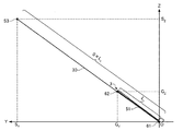
 processing unit 21 detects the hitting ball timing using the triaxial angular velocity data, but can similarly detect the hitting ball timing using the triaxial acceleration data.

1−4.スイング評価
図16は、図5のシャフトプレーン30及びホーガンプレーン40をX軸の負側から見た図(YZ平面に投影した図)である。図16に示すように、ユーザー2のダウンスイング時のゴルフクラブ3の軌跡のすべてが、シャフトプレーン30とホーガンプレーン40との間の空間であるVゾーンに含まれる場合はストレート系の打球となる可能性が高い。一方、ユーザー2のダウンスイング時のゴルフクラブ3の軌跡の一部が、Vゾーンよりも低い空間に含まれる場合はフック系の打球となり、Vゾーンよりも高い空間に含まれる場合はスライス系の打球となる可能性が高い。そこで、例えば、処理部21は、図9の工程S34において、ユーザー2のダウンスイング時のゴルフクラブ3の軌跡のすべてがVゾーンに含まれるか否かを判定してもよい。そして、処理部21は、図9の工程S36において、ダウンスイング時のゴルフクラブ3の軌跡のすべてがVゾーンに含まれていれば適正なスイングと評価し、ダウンスイング時のゴルフクラブ3の軌跡の一部がVゾーンに含まれていなければ、打球がフック系あるいはスライス系となる不適正なスイングと評価してもよい。表示する際には、プレーンで表示しなくても良く、図16のようにシャフトプレーン30の第1線分51とホーガンプレーン40の第2線分53のみを表示させ、スイングを評価しても良い。
1-4. Swing Evaluation FIG. 16 is a diagram (projected on the YZ plane) of the shaft plane 30 and the Hogan plane 40 of FIG. 5 viewed from the negative side of the X axis. As shown in FIG. 16, when all of the trajectory of the golf club 3 during the downswing of the user 2 is included in the V zone that is a space between the shaft plane 30 and the Hogan plane 40, a straight hit ball is obtained. Probability is high. On the other hand, when a part of the locus of the golf club 3 at the time of the down swing of the user 2 is included in a space lower than the V zone, it becomes a hook-type hit ball, and when it is included in a space higher than the V zone, it is a slice type There is a high possibility of hitting. Therefore, for example, the processing unit 21 may determine whether or not all of the trajectory of the golf club 3 during the downswing of the user 2 is included in the V zone in step S34 of FIG. Then, in step S36 of FIG. 9, the processing unit 21 evaluates the golf club 3 as a proper swing if all of the trajectory of the golf club 3 during the downswing is included in the V zone, and the trajectory of the golf club 3 during the downswing. If a part of the ball is not included in the V zone, it may be evaluated as an inappropriate swing in which the hit ball becomes a hook system or a slice system. When displaying, it is not necessary to display the plane, and only the first line segment 51 of the shaft plane 30 and the second line segment 53 of the Hogan plane 40 are displayed and the swing is evaluated as shown in FIG. good.

図17は、処理部21が図9の工程S32において生成し、表示部25に表示させる画像の一例である。図17に示す画像300は、シャフトプレーン30を表すポリゴン301、ホーガンプレーン40を表すポリゴン302、及び、ユーザー2のダウンスイング時のゴルフクラブ3の軌跡を表す曲線303を含んでいる。図17に示す画像300では、曲線303のすべてがポリゴン302とポリゴン303との間の空間であるVゾーンに含まれている。従って、ユーザー2は、この画像300を視認することで、自分のスイングが適正であることを確認することができる。また、処理部21は、図17に示す画像30
0(曲線303のすべてがVゾーンに含まれる画像)を表示部25に表示させる場合は、図9の工程S36において、ユーザー2のスイングが適正であると評価し、当該評価結果の情報を画像300とともに表示部25に表示させてもよい。
FIG. 17 is an example of an image generated by the processing unit 21 in step S32 of FIG. 9 and displayed on the display unit 25. An image 300 illustrated in FIG. 17 includes a polygon 301 representing the shaft plane 30, a polygon 302 representing the Hogan plane 40, and a curve 303 representing the path of the golf club 3 when the user 2 is downswing. In the image 300 shown in FIG. 17, all of the curve 303 is included in the V zone that is a space between the polygon 302 and the polygon 303. Therefore, the user 2 can confirm that his / her swing is appropriate by viewing the image 300. The processing unit 21 also displays an image 30 shown in FIG.
In the case where 0 (an image in which all of the curve 303 is included in the V zone) is displayed on the display unit 25, it is evaluated that the swing of the user 2 is appropriate in step S36 of FIG. You may display on the display part 25 with 300. FIG.

なお、図17に示す画像300は、静止画であってもよいし、動画であってもよい。また、画像300は、ユーザー2の操作に応じて表示角度(画像300を見る視点)を変えることが可能な3次元画像であってもよい。   Note that the image 300 illustrated in FIG. 17 may be a still image or a moving image. In addition, the image 300 may be a three-dimensional image in which the display angle (the viewpoint from which the image 300 is viewed) can be changed according to the operation of the user 2.

1−5.効果
本実施形態によれば、ユーザー2がスイングを開始する前に適正なドレス姿勢をとった場合には、ゴルフクラブ3やユーザー2に応じてゴルフクラブ3の傾き(傾斜角θ)の適正な範囲が決まることに着目し、傾き判定装置20は、スイング開始前の傾斜角θが、ゴルフクラブ情報242と身体情報244とに基づいて決定される基準範囲に含まれるか否かを判定する。従って、本実施形態によれば、ユーザーの運動開始前の運動器具の傾きが適正な範囲に含まれるか否かを判定することができる。特に、本実施形態によれば、傾き判定装置20は、ゴルフクラブ3の長さやユーザー2の身長、性別、年齢、国籍等に応じてより正確なゴルフクラブ3の傾き(傾斜角θ)の基準範囲を設定することにより、ユーザーの運動開始前の運動器具の傾きが適正な範囲に含まれるか否かをより正確に判定することができる。
1-5. Effect According to the present embodiment, when the user 2 takes an appropriate dressing posture before starting the swing, the golf club 3 or the user 2 has an appropriate inclination (inclination angle θ) according to the golf club 3 or the user 2. Focusing on the determination of the range, the tilt determination device 20 determines whether the tilt angle θ before the start of the swing is included in the reference range determined based on the golf club information 242 and the body information 244. Therefore, according to the present embodiment, it is possible to determine whether or not the inclination of the exercise apparatus before the start of the user's exercise is included in an appropriate range. In particular, according to the present embodiment, the inclination determination device 20 is configured to provide a more accurate reference for the inclination (inclination angle θ) of the golf club 3 in accordance with the length of the golf club 3 and the height, sex, age, nationality, etc. of the user 2. By setting the range, it can be more accurately determined whether or not the inclination of the exercise apparatus before the start of the user's exercise is included in an appropriate range.

そして、本実施形態によれば、傾き判定装置20は、ユーザーの運動開始前の運動器具の傾きが適正な範囲に含まれる場合のみ、ユーザー2にスイング開始の許可を通知するので、ユーザー2は、適正なアドレス姿勢がとれたか否かを確認し、より良いスイングを行うことができる。   And according to this embodiment, since the inclination determination apparatus 20 notifies the user 2 permission to start the swing only when the inclination of the exercise apparatus before the user's exercise is included in an appropriate range, the user 2 Thus, it is possible to check whether or not an appropriate address posture has been taken and perform a better swing.

また、本実施形態によれば、傾き判定装置20は、ユーザー2が、計測開始操作を行った後にゴルフクラブ3を壁に立て掛けた場合やアドレス姿勢をとる前に静止した場合などにおいて、所定時間計測して静止を検出しても、ゴルフクラブ3の傾き(傾斜角θ)が基準範囲に含まれなければ、スイング開始の許可を通知しないので、誤ったスイング解析結果を提示するおそれを低減させることができる。   In addition, according to the present embodiment, the tilt determination device 20 is used for a predetermined time when the user 2 leans the golf club 3 against a wall after performing a measurement start operation or when the user 2 stands still before taking an address posture. Even if measurement is performed and stillness is detected, if the inclination of the golf club 3 (inclination angle θ) is not included in the reference range, permission to start a swing is not notified, thereby reducing the possibility of presenting an incorrect swing analysis result. be able to.

また、本実施形態によれば、ユーザー2は、傾き判定装置20の表示部25に表示される画像300により、シャフトプレーン30及びホーガンプレーン40の位置や傾き、Vゾーンの大きさなどからアドレス姿勢を客観的に認識することができる。また、ユーザー2は、ダウンスイング時のゴルフクラブ3の軌道とシャフトプレーン30及びホーガンプレーン40との位置関係(ゴルフクラブ3の軌道がVゾーンに入っているか否か)を認識することができるので、スイングの良し悪しを評価することができる。   Further, according to the present embodiment, the user 2 uses the image 300 displayed on the display unit 25 of the inclination determination device 20 to determine the address posture based on the position and inclination of the shaft plane 30 and the Hogan plane 40, the size of the V zone, and the like. Can be recognized objectively. Further, the user 2 can recognize the positional relationship between the path of the golf club 3 during the downswing and the shaft plane 30 and the Hogan plane 40 (whether the path of the golf club 3 is in the V zone). , You can evaluate the quality of the swing.

また、本実施形態によれば、傾き判定装置20は、ユーザー2の両肩を結ぶ線分上の所定位置63のZ座標Aを、シャフトプレーン30にあるグリップエンドの位置62のZ座標Gとユーザー2の腕の長さLとの和とすることで、ユーザー2の体型に合ったホーガンプレーン40を特定することができる。 Further, according to this embodiment, the inclination judgment unit 20, the Z-coordinate A Z of the predetermined position 63 on the line connecting both shoulders of the user 2, Z coordinate G position 62 of the grip end in the shaft plane 30 By making the sum of Z and the arm length L 2 of the user 2, the Hogan plane 40 that matches the body shape of the user 2 can be specified.

また、本実施形態によれば、傾き判定装置20は、統計データに基づいて導出される身長と腕の長さとの間の相関式を用いて、ユーザー2の身体情報244に含まれる身長の情報から腕の長さLを計算するので、ユーザー2は、通常は正確な数値を知らない腕の長さの情報を入力する必要がなく、利便性もよい。 In addition, according to the present embodiment, the inclination determination device 20 uses the correlation formula between the height and the arm length derived based on the statistical data, and the height information included in the body information 244 of the user 2. since calculating the arm length L 2 from the user 2 is normally no need to input the information of the length of the arm that does not know the exact number may convenience.

また、本実施形態によれば、センサーユニット10を用いてシャフトプレーン30及びホーガンプレーン40を特定するので、カメラなどの大掛かりな装置を使用する必要がな
く、スイング解析を行う場所の制約が少ない。
Moreover, according to this embodiment, since the shaft plane 30 and the Hogan plane 40 are specified using the sensor unit 10, it is not necessary to use a large-scale device such as a camera, and there are few restrictions on the place where the swing analysis is performed.

また、本実施形態によれば、傾き判定装置20は、ダウンスイングにおけるゴルフクラブ3の軌跡がVゾーンに入るか否かを判定し、判定結果に基づくスイングの評価情報を提示するので、ユーザー2は、スイングの良し悪しを客観的かつ容易に評価することができる。   Further, according to the present embodiment, the inclination determination device 20 determines whether or not the locus of the golf club 3 in the downswing enters the V zone, and presents the swing evaluation information based on the determination result, so that the user 2 Can objectively and easily evaluate whether the swing is good or bad.

2.変形例
本発明は本実施形態に限定されず、本発明の要旨の範囲内で種々の変形実施が可能である。
2. The present invention is not limited to this embodiment, and various modifications can be made within the scope of the present invention.

例えば、上記の実施形態では、第1特定部213と第2特定部214は、傾き算出部211が算出したゴルフクラブ3の傾き(傾斜角θ)が基準範囲に含まれる場合に、それぞれ第1線分51(あるいはシャフトプレーン30)と第2線分53(あるいはホーガンプレーン40)を特定する処理を行う(傾斜角θが基準範囲に含まれない場合は当該処理を行わない)が、本発明はこれに限られない。例えば、ユーザー2が所定時間継続して静止していることが検出された場合には、傾斜角θが基準範囲に含まれるか否かによらず、第1特定部213と第2特定部214が上記の処理を行い、傾斜角θが基準範囲に含まれるに、画像データ生成部216が、シャフトプレーン30のポリゴンデータ、ホーガンプレーン40のポリゴンデータ及びゴルフクラブ3の軌跡を表す曲線データを含む画像データを生成する(傾斜角θが基準範囲に含まれない場合は当該画像データを生成しない)ようにしてもよい。   For example, in the above-described embodiment, the first specifying unit 213 and the second specifying unit 214 are each first when the inclination (inclination angle θ) of the golf club 3 calculated by the inclination calculating unit 211 is included in the reference range. A process of specifying the line segment 51 (or shaft plane 30) and the second line segment 53 (or Hogan plane 40) is performed (the process is not performed when the inclination angle θ is not included in the reference range). Is not limited to this. For example, when it is detected that the user 2 is stationary for a predetermined time, the first specifying unit 213 and the second specifying unit 214 are independent of whether the inclination angle θ is included in the reference range. However, the image data generation unit 216 includes the polygon data of the shaft plane 30, the polygon data of the Hogan plane 40, and the curve data representing the locus of the golf club 3, while the inclination angle θ is included in the reference range. Image data may be generated (if the inclination angle θ is not included in the reference range, the image data is not generated).

また、上記の実施形態では、傾き算出部211は、センサーユニット10の計測データを用いて、スイング開始前のゴルフクラブ3の傾き(傾斜角θ)を直接的に算出し、判定部212は、傾斜角θが基準範囲に含まれるか否かを直接的に判定しているが、本発明はこれに限られない。例えば、ゴルフクラブ3の長軸方向とセンサーユニット10の各検出軸とのなす角度が既知である場合に、傾き算出部211は、センサーユニット10の計測データを用いて、センサーユニット10の傾き(例えば、1つの検出軸の水平面(XY平面)に対する傾斜角)あるいは姿勢を算出し、判定部212は、ゴルフクラブ3の傾斜角θの基準範囲に対応するセンサーユニット10の傾きあるいは姿勢の範囲を規定する情報に基づき、センサーユニット10の傾きあるいは姿勢が当該範囲に含まれるか否かを判定することにより、傾斜角θが基準範囲に含まれるか否かを間接的に判定してもよい。   In the above embodiment, the inclination calculation unit 211 directly calculates the inclination (inclination angle θ) of the golf club 3 before the start of the swing using the measurement data of the sensor unit 10. Although it is directly determined whether or not the inclination angle θ is included in the reference range, the present invention is not limited to this. For example, when the angle formed by the major axis direction of the golf club 3 and each detection axis of the sensor unit 10 is known, the inclination calculation unit 211 uses the measurement data of the sensor unit 10 to determine the inclination of the sensor unit 10 ( For example, the inclination angle) or attitude of one detection axis with respect to the horizontal plane (XY plane) is calculated, and the determination unit 212 determines the inclination or attitude range of the sensor unit 10 corresponding to the reference range of the inclination angle θ of the golf club 3. Whether or not the inclination angle θ is included in the reference range may be indirectly determined by determining whether or not the inclination or posture of the sensor unit 10 is included in the range based on the information to be defined.

また、上記の実施形態では、第2特定部214は、ユーザー2の頭部と胸部の間(例えば、両肩を結ぶ線分上)の所定位置63のZ座標Aを、式(9)のように、グリップエンドの位置62のY座標Gとユーザー2の腕の長さLの和として計算しているが、これ以外の式を用いてもよい。例えば、第2特定部214は、A=G+K・Lのように、Lに係数Kを乗じてGに加算してAを求めてもよい。 In the above embodiment, the second specific portion 214, between the user 2 head and chest (e.g., line on connecting both shoulders) Z coordinate A Z at a predetermined position 63 of formula (9) As described above, the calculation is performed as the sum of the Y coordinate G Y of the grip end position 62 and the arm length L 2 of the user 2, but other expressions may be used. For example, the second identification unit 214, as A Z = G Y + K · L 2, may be obtained A Z by adding the G Y is multiplied by coefficient K to L 2.

また、上記の実施形態では、処理部21は、ゴルフクラブ3に装着したセンサーユニット10の計測データを用いて、シャフトプレーン及びホーガンプレーンを特定し、スイング中のゴルフクラブ3の軌跡を計算しているが、これ以外にも、例えば、ユーザー2の腕(手首など)に装着したセンサーユニット10の計測データを用いて、上記実施形態と同様の方法で、シャフトプレーン及びホーガンプレーンの特定やゴルフクラブ3の軌跡の計算を行ってもよい。あるいは、ゴルフクラブ3やユーザー2の腕あるいは肩などの部位に、複数のセンサーユニット10を装着し、当該複数のセンサーユニット10の各々の計測データを用いて、シャフトプレーン及びホーガンプレーンの特定やゴルフクラブ3の軌跡の計算を行ってもよい。   Moreover, in said embodiment, the process part 21 specifies a shaft plane and a Hogan plane using the measurement data of the sensor unit 10 with which the golf club 3 was mounted | worn, and calculates the locus | trajectory of the golf club 3 in swing. However, other than this, for example, by using the measurement data of the sensor unit 10 attached to the arm (wrist etc.) of the user 2, the shaft plane and the Hogan plane can be specified and the golf club by the same method as the above embodiment. 3 trajectories may be calculated. Alternatively, a plurality of sensor units 10 are attached to the golf club 3 or the user 2 such as an arm or a shoulder, and the measurement data of each of the plurality of sensor units 10 is used to specify the shaft plane and the Hogan plane or to play golf. The trajectory of club 3 may be calculated.

また、上記の実施形態では、第2特定部214は、ユーザー2の身体情報を用いてユーザー2の頭部と胸部の間(例えば、両肩を結ぶ線分上)の所定位置63の座標を算出し、第2軸である第2線分53やホーガンプレーン40を特定しているが、本発明はこれに限られない。例えば、第2特定部214は、第1特定部213が特定した第1軸である第1線分51とシャフトプレーン30を、それぞれX軸周りに所定の角度(例えば30°)だけ回転させたものを第2線分53とホーガンプレーン40として特定してもよい。   In the above embodiment, the second specifying unit 214 uses the body information of the user 2 to calculate the coordinates of the predetermined position 63 between the head and the chest of the user 2 (for example, on a line segment connecting both shoulders). Although the second line segment 53 and the Hogan plane 40 which are the second axes are specified, the present invention is not limited to this. For example, the second specifying unit 214 rotates the first line segment 51 and the shaft plane 30 that are the first axes specified by the first specifying unit 213 by a predetermined angle (for example, 30 °) around the X axis. A thing may be specified as the second line segment 53 and the Hogan plane 40.

また、上記の実施形態では、処理部21は、センサーユニットが計測した3軸角速度の合成値として式(14)に示すような二乗和の平方根を用いて、ユーザー2が打球したタイミング(インパクト)を検出しているが、3軸角速度の合成値として、これ以外にも、例えば、3軸角速度の二乗和、3軸角速度の和あるいはその平均値、3軸角速度の積等を用いてもよい。また、3軸角速度の合成値に代えて、3軸加速度の二乗和あるいはその平方根、3軸加速度の和あるいはその平均値、3軸加速度の積等の3軸加速度の合成値を用いてもよい。   Further, in the above embodiment, the processing unit 21 uses the square root of the sum of squares as shown in Expression (14) as the combined value of the triaxial angular velocities measured by the sensor unit, and the timing (impact) when the user 2 hits the ball. In addition to this, as a composite value of the triaxial angular velocity, for example, a sum of squares of the triaxial angular velocity, a sum of the three axial angular velocities, or an average value thereof, a product of the three axial angular velocities, or the like may be used. . Instead of the combined value of the three-axis angular velocities, a combined value of the three-axis accelerations such as a sum of squares of the three-axis accelerations or a square root thereof, a sum of the three-axis accelerations or an average value thereof, and a product of the three-axis accelerations may be used. .

また、上記の実施形態では、加速度センサー12と角速度センサー14が、センサーユニット10に内蔵されて一体化されているが、加速度センサー12と角速度センサー14は一体化されていなくてもよい。あるいは、加速度センサー12と角速度センサー14が、センサーユニット10に内蔵されずに、ゴルフクラブ3又はユーザー2に直接装着されてもよい。また、上記の実施形態では、センサーユニット10と傾き判定装置20が別体であるが、これらを一体化してゴルフクラブ3又はユーザー2に装着可能にしてもよい。また、センサーユニット10が、慣性センサー(例えば、加速度センサー12あるいは角速度センサー14)とともに、傾き算出部211、判定部212、あるいは、傾き判定装置20のその他の構成要素を備え、本発明の傾き判定装置として機能してもよい。   In the above embodiment, the acceleration sensor 12 and the angular velocity sensor 14 are integrated in the sensor unit 10, but the acceleration sensor 12 and the angular velocity sensor 14 may not be integrated. Alternatively, the acceleration sensor 12 and the angular velocity sensor 14 may be directly attached to the golf club 3 or the user 2 without being built in the sensor unit 10. Further, in the above embodiment, the sensor unit 10 and the tilt determination device 20 are separate bodies, but they may be integrated so as to be mountable to the golf club 3 or the user 2. In addition, the sensor unit 10 includes an inertial sensor (for example, the acceleration sensor 12 or the angular velocity sensor 14) and the tilt calculation unit 211, the determination unit 212, or other components of the tilt determination device 20, and the tilt determination of the present invention. It may function as a device.

また、上記の実施形態では、ゴルフスイングを解析する傾き判定システム(傾き判定装置)を例に挙げたが、本発明は、テニスや野球などの様々な運動において、運度開始前の運動器具の傾きが基準範囲に含まれるか否かを判定する傾き判定システム(傾き判定装置)に適用することができる。   In the above-described embodiment, the tilt determination system (tilt determination device) that analyzes the golf swing is taken as an example. However, the present invention is applicable to various exercises such as tennis and baseball before the start of luck. The present invention can be applied to an inclination determination system (inclination determination apparatus) that determines whether an inclination is included in a reference range.

上述した実施形態および変形例は一例であって、これらに限定されるわけではない。例えば、各実施形態および各変形例を適宜組み合わせることも可能である。   The above-described embodiments and modifications are merely examples, and the present invention is not limited to these. For example, it is possible to appropriately combine each embodiment and each modification.

本発明は、実施の形態で説明した構成と実質的に同一の構成(例えば、機能、方法及び結果が同一の構成、あるいは目的及び効果が同一の構成)を含む。また、本発明は、実施の形態で説明した構成の本質的でない部分を置き換えた構成を含む。また、本発明は、実施の形態で説明した構成と同一の作用効果を奏する構成又は同一の目的を達成することができる構成を含む。また、本発明は、実施の形態で説明した構成に公知技術を付加した構成を含む。   The present invention includes configurations that are substantially the same as the configurations described in the embodiments (for example, configurations that have the same functions, methods, and results, or configurations that have the same objects and effects). In addition, the invention includes a configuration in which a non-essential part of the configuration described in the embodiment is replaced. In addition, the present invention includes a configuration that exhibits the same operational effects as the configuration described in the embodiment or a configuration that can achieve the same object. Further, the invention includes a configuration in which a known technique is added to the configuration described in the embodiment.

1 傾き判定システム、2 ユーザー、3 ゴルフクラブ、4 ゴルフボール、10 センサーユニット、12 加速度センサー、14 角速度センサー、16 信号処理部、18 通信部、20 傾き判定装置、21 処理部、22 通信部、23 操作部、24 記憶部、25 表示部、26 音出力部、30 シャフトプレーン、40 ホーガンプレーン、51 第1線分、52 第3線分、53 第2線分、61 ゴルフクラブのヘッドの位置、62 ゴルフクラブのグリップエンドの位置、63 ユーザーの両肩を結ぶ線分上の所定位置、210 データ取得部、211 傾き算出部、212 判定部、213 第1特定部、214 第2特定部、215 運動解析部、216 画像データ生成部、217 記憶処理部、218 表示処理部、219 音出力処理部、240 運動解析プロ
グラム、242 ゴルフクラブ情報、244身体情報、246 センサー装着位置情報、248 基準範囲情報、300 画像、301 シャフトプレーンを表すポリゴン、302 ホーガンプレーンを表すポリゴン、303 ダウンスイング時のゴルフクラブの軌跡を表す曲線
1 tilt determination system, 2 users, 3 golf clubs, 4 golf balls, 10 sensor unit, 12 acceleration sensor, 14 angular velocity sensor, 16 signal processing unit, 18 communication unit, 20 tilt determination device, 21 processing unit, 22 communication unit, 23 Operation unit, 24 Storage unit, 25 Display unit, 26 Sound output unit, 30 Shaft plane, 40 Hogan plane, 51 First line segment, 52 Third line segment, 53 Second line segment, 61 Position of golf club head 62, the position of the grip end of the golf club, 63 a predetermined position on a line segment connecting both shoulders of the user, 210 data acquisition unit, 211 inclination calculation unit, 212 determination unit, 213 first identification unit, 214 second identification unit, 215 motion analysis unit, 216 image data generation unit, 217 storage processing unit, 218 display processing unit, 219 sound output processing unit, 240 exercise Analysis program, 242 golf club information, 244 body information, 246 sensor mounting position information, 248 reference range information, 300 images, 301 polygon representing shaft plane, 302 polygon representing Hogan plane, 303 golf club trajectory during downswing Representing curve

Claims (12)

慣性センサーの出力信号を用いて、運動開始前の運動器具の傾きを算出する傾き算出部と、
前記運動器具の傾きが、前記運動器具に関する情報とユーザーの身体情報とに基づいて決定される基準範囲に含まれるか否かを判定する判定部と、を含む、傾き判定装置。
Using an output signal of the inertial sensor, an inclination calculating unit for calculating an inclination of the exercise apparatus before starting exercise,
And a determination unit that determines whether or not the inclination of the exercise equipment is included in a reference range that is determined based on information related to the exercise equipment and physical information of the user.
前記身体情報は、身長、腕の長さ及び脚の長さの少なくとも1つの情報を含む、請求項1に記載の傾き判定装置。   The inclination determination apparatus according to claim 1, wherein the body information includes at least one information of a height, an arm length, and a leg length. 前記身体情報は、さらに性別の情報を含む、請求項2に記載の傾き判定装置。   The inclination determination apparatus according to claim 2, wherein the physical information further includes sex information. 前記運動器具に関する情報は、前記運動器具の長さの情報および前記運動器具の種類の情報の少なくとも一方である、請求項1乃至3のいずれか一項に記載の傾き判定装置。   The inclination determination apparatus according to any one of claims 1 to 3, wherein the information on the exercise equipment is at least one of information on a length of the exercise equipment and information on a type of the exercise equipment. 前記判定部によって前記運動器具の傾きが前記基準範囲に含まれると判定された場合に、運動の開始の許可を通知する通知部を含む、請求項1乃至4のいずれか一項に記載の傾き判定装置。   The inclination according to any one of claims 1 to 4, further comprising a notification unit that notifies permission to start exercise when the determination unit determines that the inclination of the exercise apparatus is included in the reference range. Judgment device. 前記判定部によって前記運動器具の傾きが前記基準範囲に含まれると判定された場合に、前記慣性センサーの出力信号を用いて、前記運動器具の長軸方向に沿った第1軸を特定する第1特定部を含む、請求項1乃至5のいずれか一項に記載の傾き判定装置。   When the determination unit determines that the inclination of the exercise apparatus is included in the reference range, the first axis that identifies the first axis along the longitudinal direction of the exercise apparatus is determined using the output signal of the inertial sensor. The inclination determination apparatus according to any one of claims 1 to 5, including one specifying unit. 前記第1特定部は、
前記運動器具の傾きが前記基準範囲に含まれている時の前記慣性センサーの出力信号を用いて、前記第1軸を特定する、請求項6に記載の傾き判定装置。
The first specifying unit includes:
The inclination determination apparatus according to claim 6, wherein the first axis is specified using an output signal of the inertial sensor when the inclination of the exercise apparatus is included in the reference range.
前記判定部によって前記運動器具の傾きが前記基準範囲に含まれると判定された場合に、前記慣性センサーの出力信号を用いて、前記ユーザーの頭部と胸部の間の所定位置と打撃位置とを結ぶ第2軸を特定する第2特定部を含む、請求項1乃至7のいずれか一項に記載の傾き判定装置。   When the determination unit determines that the inclination of the exercise apparatus is included in the reference range, the predetermined position between the user's head and chest and the striking position are determined using the output signal of the inertial sensor. The inclination determination apparatus according to claim 1, further comprising a second specifying unit that specifies a second axis to be connected. 前記第2特定部は、
前記運動器具の傾きが前記基準範囲に含まれている時の前記慣性センサーの出力信号を用いて、前記第2軸を特定する、請求項8に記載の傾き判定装置。
The second specifying unit includes:
The inclination determination apparatus according to claim 8, wherein the second axis is specified using an output signal of the inertial sensor when the inclination of the exercise apparatus is included in the reference range.
請求項1乃至9のいずれか一項に記載の傾き判定装置と、前記慣性センサーと、を含む、傾き判定システム。   An inclination determination system including the inclination determination device according to claim 1 and the inertial sensor. 慣性センサーの出力信号を用いて、運動開始前の運動器具の傾きを算出する傾き算出工程と、
前記運動器具の傾きが、前記運動器具に関する情報とユーザーの身体情報とに基づいて決定される基準範囲に含まれるか否かを判定する判定工程と、を含む、傾き判定方法。
An inclination calculation step of calculating the inclination of the exercise equipment before starting exercise using the output signal of the inertial sensor,
And a determination step of determining whether or not the inclination of the exercise equipment is included in a reference range determined based on information on the exercise equipment and user's physical information.
慣性センサーの出力信号を用いて、運動開始前の運動器具の傾きを算出する傾き算出工程と、
前記運動器具の傾きが、前記運動器具に関する情報とユーザーの身体情報とに基づいて決定される基準範囲に含まれるか否かを判定する判定工程と、をコンピューターに実行させる、プログラム。
An inclination calculation step of calculating the inclination of the exercise equipment before starting exercise using the output signal of the inertial sensor,
A program for causing a computer to execute a determination step of determining whether or not the inclination of the exercise equipment is included in a reference range determined based on information related to the exercise equipment and physical information of the user.
JP2014258824A 2014-12-19 2014-12-22 Tilt determination device, tilt determination system, tilt determination method and program Pending JP2016116745A (en)

Priority Applications (2)

Application Number Priority Date Filing Date Title
JP2014258824A JP2016116745A (en) 2014-12-22 2014-12-22 Tilt determination device, tilt determination system, tilt determination method and program
US14/965,375 US20160175650A1 (en) 2014-12-19 2015-12-10 Inclination determination device, inclination determination system, inclination determination method, exercise analysis device, exercise analysis system, exercise analysis method, and recording medium

Applications Claiming Priority (1)

Application Number Priority Date Filing Date Title
JP2014258824A JP2016116745A (en) 2014-12-22 2014-12-22 Tilt determination device, tilt determination system, tilt determination method and program

Publications (1)

Publication Number Publication Date
JP2016116745A true JP2016116745A (en) 2016-06-30

Family

ID=56242595

Family Applications (1)

Application Number Title Priority Date Filing Date
JP2014258824A Pending JP2016116745A (en) 2014-12-19 2014-12-22 Tilt determination device, tilt determination system, tilt determination method and program

Country Status (1)

Country Link
JP (1) JP2016116745A (en)

Cited By (3)

* Cited by examiner, † Cited by third party
Publication number Priority date Publication date Assignee Title
JP2019524392A (en) * 2017-03-17 2019-09-05 リッキー,ブレット Method and apparatus for simulating gaming events
JP2020116475A (en) * 2020-05-18 2020-08-06 カシオ計算機株式会社 Motion analysis device, and motion analysis method and program
JP2020137565A (en) * 2019-02-26 2020-09-03 H2L株式会社 Pose determination system

Cited By (6)

* Cited by examiner, † Cited by third party
Publication number Priority date Publication date Assignee Title
JP2019524392A (en) * 2017-03-17 2019-09-05 リッキー,ブレット Method and apparatus for simulating gaming events
JP7133546B2 (en) 2017-03-17 2022-09-08 リッキー,ブレット Method and Apparatus for Simulating Gaming Events
JP2020137565A (en) * 2019-02-26 2020-09-03 H2L株式会社 Pose determination system
JP7212934B2 (en) 2019-02-26 2023-01-26 H2L株式会社 Pose judgment system
JP2020116475A (en) * 2020-05-18 2020-08-06 カシオ計算機株式会社 Motion analysis device, and motion analysis method and program
JP7134418B2 (en) 2020-05-18 2022-09-12 カシオ計算機株式会社 Motion analysis device, motion analysis method and program

Similar Documents

Publication Publication Date Title
US9962591B2 (en) Motion analysis method, program, and motion analysis device
JP6696109B2 (en) Motion analysis device, motion analysis system, motion analysis method and program
TW201501752A (en) Motion analysis method and motion analysis device
JP6613684B2 (en) Swing diagnostic method, swing diagnostic program, recording medium, swing diagnostic device, and swing diagnostic system
JP2015156882A (en) Motion analysis device and motion analysis system
JP2016067410A (en) Motion analysis device, motion analysis system, and motion analysis method and program
JP2017023639A (en) Swing diagnostic device, swing diagnostic system, swing diagnostic method, swing diagnostic program and storage medium
JP2017023638A (en) Swing diagnostic device, swing diagnostic system, swing diagnostic method, swing diagnostic program and storage medium
JP2017086164A (en) Electronic apparatus, system, method, program, and recording medium
JP2017029516A (en) Golf swing analysis device
US20160175650A1 (en) Inclination determination device, inclination determination system, inclination determination method, exercise analysis device, exercise analysis system, exercise analysis method, and recording medium
KR20160106670A (en) Movement analysis method, movement analysis device, movement analysis system and program
US10286285B2 (en) Display method, display apparatus, motion analysis system, motion analysis program, and recording medium
US10252136B2 (en) Swing diagnosis apparatus, swing diagnosis system, swing diagnosis method, and recording medium
JP6380733B2 (en) Motion analysis device, motion analysis system, motion analysis method, motion analysis information display method and program
JP2016116566A (en) Motion analysis device, motion analysis method, program, and motion analysis system
JP2016116615A (en) Motion analysis device, motion analysis system, motion analysis method, and program
WO2015146062A1 (en) Motion analysis method, motion analysis device, motion analysis system and program
JP2017023644A (en) Arithmetic device, arithmetic system, arithmetic method, arithmetic program, and storage medium
JP2016116613A (en) Motion analysis device, motion analysis system, motion analysis method, and program
US20170203188A1 (en) Display method, motion analysis apparatus, motion analysis system, motion analysis program, and recording medium
JP2017086850A (en) Electronic apparatus, system, method, program, and recording medium
JP2016116745A (en) Tilt determination device, tilt determination system, tilt determination method and program
JP2016055028A (en) Motion analysis method, motion analysis device, motion analysis system and program
US20160175649A1 (en) Exercise analysis device, exercise analysis method, program, recording medium, and exercise analysis system