JP2016115091A5 - - Google Patents

Download PDF

Info

Publication number
JP2016115091A5
JP2016115091A5 JP2014252491A JP2014252491A JP2016115091A5 JP 2016115091 A5 JP2016115091 A5 JP 2016115091A5 JP 2014252491 A JP2014252491 A JP 2014252491A JP 2014252491 A JP2014252491 A JP 2014252491A JP 2016115091 A5 JP2016115091 A5 JP 2016115091A5
Authority
JP
Japan
Prior art keywords
card
detection
pair
transport
roller
Prior art date
Legal status (The legal status is an assumption and is not a legal conclusion. Google has not performed a legal analysis and makes no representation as to the accuracy of the status listed.)
Granted
Application number
JP2014252491A
Other languages
Japanese (ja)
Other versions
JP6424328B2 (en
JP2016115091A (en
Filing date
Publication date
Application filed filed Critical
Priority claimed from JP2014252491A external-priority patent/JP6424328B2/en
Priority to JP2014252491A priority Critical patent/JP6424328B2/en
Priority to EP15196434.3A priority patent/EP3032464B1/en
Priority to KR1020150166083A priority patent/KR101685030B1/en
Priority to AU2015261739A priority patent/AU2015261739B2/en
Priority to US14/965,315 priority patent/US9708125B2/en
Priority to CN201510920607.6A priority patent/CN105701517B/en
Publication of JP2016115091A publication Critical patent/JP2016115091A/en
Publication of JP2016115091A5 publication Critical patent/JP2016115091A5/ja
Publication of JP6424328B2 publication Critical patent/JP6424328B2/en
Application granted granted Critical
Active legal-status Critical Current
Anticipated expiration legal-status Critical

Links

Images

Description

カード処理装置Card processing device

本発明は、カードを内部に取り込んで所定の処理を行うカード処理装置に関する。特に、透光性を有するカードに好適に使用できるものである。   The present invention relates to a card processing apparatus that takes in a card and performs a predetermined process. In particular, it can be suitably used for a translucent card.

本明細書において「カード」とは、広くカード状の物品を意味しており、透光性を有するカード型の情報記憶媒体(情報記憶媒体カード)のほか、透光性や情報記憶機能を持たないカードやカード状物品も含む。具体的には、テレフォンカード、プリペイドカード、キャラクターカード、ブロマイド、アミューズメント用カード、クレジットカードやバンクカードなどの磁気ストライプカードや、ICカードおよびバーコード付きカード、さらには、この種のカードと同等またはそれよりも厚みがある紙製等の薄板状物品等を含む。   In this specification, “card” widely means a card-like article, and has translucency and an information storage function in addition to a translucent card-type information storage medium (information storage medium card). Includes no cards or card-like items. Specifically, telephone cards, prepaid cards, character cards, bromides, amusement cards, magnetic stripe cards such as credit cards and bank cards, IC cards and cards with barcodes, or equivalent to this kind of cards It includes a thin plate-like article made of paper or the like having a greater thickness.

本発明に関連する第1の従来技術としては、特許文献1に開示されたカード取扱装置がある。このカード取扱装置は、情報記憶部を有するカードの挿入を受けるカード挿入口と、前記カード挿入口に挿入されたカードを搬送するカード搬送手段と、前記カード搬送手段で搬送されたカードから前記情報記憶部の情報を読み取るカード情報読取手段と、前記カード情報読取手段が読み取りをする位置にカードが搬送されたことを検出するカード読取位置検出手段とを有するカード取扱装置である。前記カード読取位置検出手段は、カードが前記カード搬送手段で搬送される場合の前記情報記憶部の軌跡上に配置され、且つ、前記カード搬送手段によるカードの搬送方向に対して前記カード情報読取手段の前または後の少なくとも一方に設置されている。   As a first conventional technique related to the present invention, there is a card handling device disclosed in Patent Document 1. The card handling device includes a card insertion slot that receives an insertion of a card having an information storage unit, a card conveyance unit that conveys a card inserted into the card insertion slot, and the information from the card conveyed by the card conveyance unit. A card handling device having card information reading means for reading information in a storage unit and card reading position detecting means for detecting that a card has been conveyed to a position where the card information reading means reads. The card reading position detecting means is arranged on a locus of the information storage unit when the card is conveyed by the card conveying means, and the card information reading means with respect to the card conveying direction by the card conveying means It is installed at least one before or after.

具体的に言うと、このカード取り扱い装置は、前記カード読取位置検出手段としてのセンサ、具体的には、カード挿入検出用の光センサ(第1センサ)と、カード位置検出用の光センサ(第2センサ)と、磁気ヘッドの前方(上流側)に配置されるデータ読み取りタイミング計測用の光センサ(第3センサ)、および/または、磁気ヘッドの後方(下流側)に配置されるデータ読み取りタイミング計測用の光センサ(第4センサ)を、いずれも、前記カード搬送手段によって搬送されるカードの前記情報記憶部(例えば磁気ストライプ)の軌跡上に配置したものである。このように構成することで、搬送中に前記情報記憶部が確実に前記光センサで検出されるようになるため、前記情報記憶部以外を透明にしたカード(いわゆるスケルトンカード)をも確実に検出することができる、とされている。   More specifically, the card handling device includes a sensor as the card reading position detecting means, specifically, an optical sensor for detecting card insertion (first sensor) and an optical sensor for detecting card position (first sensor). 2 sensors), an optical sensor (third sensor) for measuring data reading timing arranged in front (upstream side) of the magnetic head, and / or data reading timing arranged in the rear (downstream side) of the magnetic head. All of the optical sensors for measurement (fourth sensor) are arranged on the locus of the information storage unit (for example, magnetic stripe) of the card conveyed by the card conveying means. With this configuration, the information storage unit is reliably detected by the optical sensor during conveyance, so that a card (so-called skeleton card) that is transparent except for the information storage unit is also reliably detected. It can be done.

本発明に関連する第2の従来技術としては、特許文献2に開示されたカード処理装置がある。このカード処理装置は、カード搬送路のカード挿入口に設けられた光学式の挿入検出用センサと、前記挿入検出用センサから規定の間隔をおいてカード挿入方向の下流側に設けられた光学式の長さ検出用センサと、カード搬送路内のカードに送りをかけるカード搬送機構と、前記挿入検出用センサおよび前記長さ検出用センサからの信号に基づいて前記カード搬送機構の作動状態を制御する搬送コントローラとを備えたカード処理装置である。前記挿入検出用センサと前記長さ検出用センサとの間のカード搬送路上には、カードが透明であるか不透明であるかに関わりなくカードの存在の有無を検出するカード検出用センサを配備している。前記搬送コントローラには、前記挿入検出用センサからのカード検出信号を受けて前記カード搬送機構をカード挿入方向に駆動するカード取り込み制御手段と、前記挿入検出用センサからの信号と前記長さ検出用センサからの信号とに基づいて、カードの不透明部分の長さが規定の長さに達しているか否かを判定する長さ判定手段と、前記長さ判定手段によってカードの不透明部分の長さが規定の長さに達していると判定された場合には、前記カード搬送機構によるカードの取り込みを継続する一方、カードの不透明部分の長さが規定の長さに達していないと判定された場合には、さらに、前記カード検出用センサによってカードが検出されているか否かを判定し、カードが検出されていれば、前記カード搬送機構をカード排出方向に駆動してカード挿入口からカードを排出してから前記カード搬送機構を初期状態に復帰させ、カードが検出されていなければ、前記カード搬送機構を直ちに初期状態に復帰させるカード返却動作規制手段とを備えている。   As a second prior art related to the present invention, there is a card processing device disclosed in Patent Document 2. The card processing device includes an optical insertion detection sensor provided at a card insertion port of a card conveyance path, and an optical type provided downstream of the insertion detection sensor at a predetermined interval from the insertion detection sensor. Length control sensor, a card transport mechanism that feeds the card in the card transport path, and the operation state of the card transport mechanism is controlled based on signals from the insertion detection sensor and the length detection sensor It is a card processing apparatus provided with the conveyance controller which performs. A card detection sensor is provided on the card conveyance path between the insertion detection sensor and the length detection sensor to detect the presence or absence of the card regardless of whether the card is transparent or opaque. ing. The transport controller receives a card detection signal from the insertion detection sensor, drives the card transport mechanism in the card insertion direction, a signal from the insertion detection sensor and the length detection Based on the signal from the sensor, a length determination means for determining whether or not the length of the opaque portion of the card has reached a specified length, and the length of the opaque portion of the card is determined by the length determination means. When it is determined that the specified length has been reached, the card transport mechanism continues to take in the card, while it is determined that the length of the opaque portion of the card has not reached the specified length. Further, it is determined whether or not a card is detected by the card detection sensor. If a card is detected, the card transport mechanism is driven in the card ejection direction. A card return operation restricting means for returning the card transport mechanism to the initial state after discharging the card from the card insertion slot, and immediately returning the card transport mechanism to the initial state if no card is detected; .

このカード処理装置では、前記挿入検出用センサと前記長さ検出用センサ(いずれも光学式センサである)との間の前記カード搬送路上に前記カード検出用センサを配備することにより、カードが透明であるか不透明であるかに関わりなく、カードの存在の有無を判定できるようにしている。そして、前記カード返却動作規制手段により、カードが検出されている場合に限って、前記カード搬送機構を前記カード排出方向に駆動して前記カード挿入口から排出する一方、カードが検出されていない場合には、前記カード搬送機構を直ちに初期状態に復帰させて次のカードの挿入に備えるようにしている。このため、透明部分を有するカードの取り扱いに際し、カードの不透明部分が前記挿入検出用センサと前記長さ検出用センサの間に位置することで、前記挿入検出用センサと前記長さ検出用センサによるカードの検出が不能となった状況下でも、無意味な返却処理を防止して、当該カード処理装置の運用効率を向上させることができる、とされている。   In this card processing device, the card is made transparent by disposing the card detection sensor on the card conveyance path between the insertion detection sensor and the length detection sensor (both are optical sensors). Regardless of whether the card is opaque or not, the presence or absence of the card can be determined. And only when a card is detected by the card return operation restricting means, the card transport mechanism is driven in the card discharge direction to be discharged from the card insertion slot, but no card is detected. The card transport mechanism is immediately returned to the initial state to prepare for the insertion of the next card. For this reason, when handling a card having a transparent portion, the opaque portion of the card is positioned between the insertion detection sensor and the length detection sensor, so that the insertion detection sensor and the length detection sensor It is said that even when the card cannot be detected, meaningless return processing can be prevented and the operational efficiency of the card processing apparatus can be improved.

特開2005−173947号(図3、請求項1、段落番号0009,0014〜0016、0023〜0024)JP-A-2005-173947 (FIG. 3, claim 1, paragraph numbers 0009, 0014 to 0016, 0023 to 0024) 特許第4888789号(図2、図4、請求項1、段落番号0023、0034〜0043、0048〜0072)Japanese Patent No. 4888789 (FIGS. 2 and 4, claim 1, paragraph numbers 0023, 0034 to 0043, 0048 to 0072)

しかしながら、上述した特許文献1に開示されたカード取扱装置では、前記カード挿入口から誤った状態でスケルトンカードが挿入された場合には、当該カード取扱装置内において取り込まれたカードを正常に取り扱いできなくなるという問題がある。   However, in the card handling device disclosed in Patent Document 1 described above, when a skeleton card is inserted in an erroneous state from the card insertion slot, the card taken in the card handling device can be handled normally. There is a problem of disappearing.

例えば、スケルトンカードが表裏反転して、あるいは、前後反転して挿入された場合や、全面が透光性を持ち情報記憶部を持たないカードが挿入されたような場合には、当該カード取扱装置内に取り込まれたカードから情報を読み取ったり、当該カードに情報を書き込んだりすることができない。これは、取り込まれたスケルトンカードの情報記憶部を、カード読取位置検出手段としての複数の光センサで検出できないからである。したがって、当該カードを正常に取り扱うことができず、直ちに「エラー」として前記カード挿入口に向けて排出する動作を実行しなければならない。   For example, when a skeleton card is inserted upside down or reversed upside down, or when a card that is entirely translucent and does not have an information storage unit is inserted, the card handling device It is impossible to read information from a card taken in or write information to the card. This is because the information storage unit of the captured skeleton card cannot be detected by a plurality of optical sensors as card reading position detecting means. Accordingly, the card cannot be handled normally, and an operation of immediately ejecting the card toward the card insertion slot as an “error” must be executed.

また、上述した特許文献2に開示されたカード処理装置では、前記カード搬送路上に配備された前記カード検出用センサにより、スケルトンカードであるか否かに関係なくカードの有無を検出することができる。しかし、前記挿入検出用センサと前記長さ検出用センサは、いずれも光学式センサで構成されているため、これら二つのセンサは、前記カード挿入口から挿入されたスケルトンカードの不透明な情報記憶部を検出できる位置に配置されている。このため、スケルトンカードが表裏反転して、あるいは、前後反転して挿入された場合や、全面が透光性を持ち情報記憶部を持たないカードが挿入されたような場合には、前記カード挿入口へのスケルトンカードの挿入の有無と、当該カード処理装置内でのスケルトンカードの位置を検出することができないという問題がある。   Moreover, in the card processing apparatus disclosed in Patent Document 2 described above, the presence or absence of a card can be detected by the card detection sensor provided on the card transport path regardless of whether it is a skeleton card or not. . However, since both the insertion detection sensor and the length detection sensor are optical sensors, the two sensors are opaque information storage units of the skeleton card inserted from the card insertion slot. It is arrange | positioned in the position which can detect. For this reason, if the skeleton card is inserted upside down or reversed upside down, or if a card that is entirely translucent and does not have an information storage unit is inserted, the card is inserted. There is a problem that it is impossible to detect whether or not the skeleton card is inserted into the mouth and the position of the skeleton card in the card processing apparatus.

本発明は、上述した第1及び第2の従来技術の問題点を鑑みてなされたものであり、その目的とするところは、挿入されるカードが不透明な箇所(例えば情報記憶部)を有するか否かに関わらず、また、挿入されるカードが不透明な箇所(例えば情報記憶部)を有している場合は、そのカード中での形成位置に関わらず、装置へのカード挿入の有無と装置内でのカード位置とを確実に検出することができるカード処理装置を提供することにある。   The present invention has been made in view of the above-described problems of the first and second prior arts. The object of the present invention is to determine whether the inserted card has an opaque portion (for example, an information storage unit). Regardless of whether or not the card to be inserted has an opaque portion (for example, an information storage unit), whether or not the card is inserted into the device and the device regardless of the formation position in the card. It is an object of the present invention to provide a card processing apparatus capable of reliably detecting the card position within the card.

本発明の他の目的は、使用するカードについて、不透明な箇所(例えば情報記憶部)の有無とその形成位置についての制約をなくすことができるカード処理装置を提供することにある。   Another object of the present invention is to provide a card processing apparatus that can eliminate restrictions on the presence or absence of an opaque portion (for example, an information storage unit) and the formation position of a card to be used.

本発明のさらに他の目的は、カードの挿入の有無および装置内でのカードの位置の検出を、カードの搬送やカードに対する処理(例えば、情報の読み取り及び書き込み)に支障を生じることなく、簡単な構成で実現することができるカード処理装置を提供することにある。   Still another object of the present invention is to easily detect the presence / absence of a card and the position of the card in the apparatus without causing any trouble in the card transport or processing (for example, reading and writing of information). An object of the present invention is to provide a card processing device that can be realized with a simple configuration.

ここに明記しない本発明のさらに他の目的は、以下の説明および添付図面から明らかである。   Other objects of the present invention which are not specified here will be apparent from the following description and the accompanying drawings.

(1) 上記した目的を達成するため、本発明に係るカード処理装置は、
第1カード挿入口を有する第1カード挿入部と、
前記第1カード挿入部を介して挿入されたカードを所定の搬送経路に沿って搬送する搬送部と、
前記搬送部を駆動して前記カードを前記搬送経路に沿って前方または後方に搬送する搬送機構と、
前記搬送経路内の前記第1カード挿入口に隣接する第1位置に設けられた第1カード検知部と、
前記搬送経路内において、前記搬送経路に沿って後方に前記第1カード検知部から所定距離だけ離れた第2位置に設けられた第2カード検知部と、
前記搬送経路内において、前記搬送経路に沿って後方に前記第2カード検知部から所定距離だけ離れた第3位置に設けられた第3カード検知部と、
前記第1カード検知部、前記第2カード検知部及び前記第3カード検知部からそれぞれ送出される第1信号、第2信号及び第3信号に基づいて、前記搬送機構を制御する制御部とを備え、
前記第1カード検知部、前記第2カード検知部及び前記第3カード検知部の各々は、前記搬送経路を搬送されている前記カードが接触することによって待機位置から移動位置へ変位する可動部材と、前記可動部材の前記待機位置から前記移動位置への変位を感知するセンサとを有しており、
前記制御部は、前記第1信号、前記第2信号及び前記第3信号のいずれかがカード検出またはカード非検出を伝える信号であるかに応じて、前記カードの前記第1カード挿入口からの挿入の有無と前記搬送経路上での前記カードの位置を判断することを特徴とするものである。
(1) In order to achieve the above object, a card processing device according to the present invention includes:
A first card insertion portion having a first card insertion slot;
A transport unit for transporting a card inserted through the first card insertion unit along a predetermined transport path;
A transport mechanism that drives the transport unit to transport the card forward or backward along the transport path;
A first card detector provided at a first position adjacent to the first card insertion slot in the transport path;
A second card detector provided in a second position at a predetermined distance away from the first card detector in the rear of the transport path along the transport path;
A third card detector provided in a third position at a predetermined distance away from the second card detector in the rear of the transport path along the transport path;
A control unit that controls the transport mechanism based on a first signal, a second signal, and a third signal respectively sent from the first card detection unit, the second card detection unit, and the third card detection unit; Prepared,
Each of the first card detection unit, the second card detection unit, and the third card detection unit is a movable member that is displaced from a standby position to a movement position when the card being conveyed through the conveyance path contacts. And a sensor for detecting a displacement of the movable member from the standby position to the moving position,
The control unit determines whether the first signal, the second signal, or the third signal is a signal that conveys card detection or card non-detection from the first card insertion slot of the card. The presence or absence of insertion and the position of the card on the transport path are determined.

本発明に係るカード処理装置では、前記搬送経路内の前記第1カード挿入口に隣接する前記第1位置に前記第1カード検知部を設け、前記搬送経路内において前記搬送経路に沿って後方に前記第1カード検知部から所定距離だけ離れた前記第2位置に前記第2カード検知部を設け、前記搬送経路内において前記搬送経路に沿って後方に前記第2カード検知部から所定距離だけ離れた前記第3位置に前記第3カード検知部を設けており、前記第1〜第3カード検知部からそれぞれ送出される第1〜第3信号に基づいて前記制御部によって前記搬送機構を制御するようにしている。また、前記第1〜第3カード検知部の各々は、前記搬送経路を搬送されている前記カードが接触することによって前記待機位置から前記移動位置へ変位する前記可動部材と、前記可動部の前記待機位置から前記移動位置への変位を感知する前記センサとを有していて、前記制御部が、前記第1〜第3信号のいずれがカード検出またはカード非検出を伝える信号であるかに応じて、前記カードの前記第1カード挿入口からの挿入の有無と前記搬送経路上での前記カードの位置を判断する。 In the card processing apparatus according to the present invention, the first card detection unit is provided at the first position adjacent to the first card insertion slot in the transport path, and is rearward along the transport path in the transport path. The second card detection unit is provided at the second position separated by a predetermined distance from the first card detection unit, and is separated from the second card detection unit by a predetermined distance rearwardly along the conveyance path in the conveyance path. The third card detection unit is provided at the third position, and the transport mechanism is controlled by the control unit based on first to third signals respectively sent from the first to third card detection units. I am doing so. Further, each of the first to third card detection unit, said movable member being displaced into the movement position from the standby position by the card being conveyed the conveying path are in contact, the movable member The sensor that senses displacement from the standby position to the moving position, and the control unit determines which one of the first to third signals conveys card detection or card non-detection. In response, the presence / absence of insertion of the card from the first card insertion slot and the position of the card on the transport path are determined.

したがって、挿入されるカードが不透明な箇所(例えば情報記憶部)を有するか否かに関わらず、また、挿入されるカードが不透明な箇所(例えば情報記憶部)を有している場合は、そのカード中での形成位置に関わらず、当該カード処理装置へのカード挿入の有無と当該カード処理装置内でのカード位置とを確実に検出することができる。   Therefore, regardless of whether or not the inserted card has an opaque portion (for example, an information storage unit), and when the inserted card has an opaque portion (for example, an information storage unit), Regardless of the formation position in the card, it is possible to reliably detect whether or not a card is inserted into the card processing apparatus and the card position in the card processing apparatus.

また、使用するカードについて、不透明な箇所(例えば情報記憶部)の有無とその形成位置についての制約をなくすことができる。   In addition, it is possible to eliminate restrictions on the presence / absence of an opaque portion (for example, an information storage unit) and the formation position of the card to be used.

さらに、カードの挿入の有無および装置内でのカードの位置を検出する検出手段を、カードの搬送やカードに対する処理(例えば、情報の読み取り及び書き込み)に支障を生じることなく、簡単な構成で実現することができる。   Furthermore, detection means for detecting the presence or absence of a card and the position of the card in the apparatus is realized with a simple configuration without causing any trouble in the card transport or the card processing (for example, reading and writing of information). can do.

さらに、前記搬送経路内の前記第1〜第3位置にそれぞれ第1〜第3カード検知部を設けると共に、前記第1〜第3カード検知部の各々が、前記搬送経路を搬送されている前記カードが接触することによって前記待機位置から前記移動位置へ変位する前記可動部材と、前記可動部の前記待機位置から前記移動位置への変位を感知する前記センサとを有しているため、カードの挿入の有無および装置内でのカードの位置の検出を、カードの搬送やカードに対する処理(例えば、情報の読み取り及び書き込み)に支障を生じることなく、簡単な構成で実現することができる。 Furthermore, while providing the 1st-3rd card | curd detection part in the said 1st-3rd position in the said conveyance path | route, respectively, each of the said 1st-3rd card | curd detection part is conveyed in the said conveyance path | route. because it has a movable member that is displaced into the movement position from the standby position by the card are in contact, and said sensor for sensing the displacement of the said movement position from the standby position of the movable member, the card The detection of the presence / absence of the card and the position of the card in the apparatus can be realized with a simple configuration without causing any trouble in the card transport and the card processing (for example, reading and writing of information).

(2) 本発明のカード処理装置の好ましい例では、前記可動部材の前記待機位置が、前記搬送経路を搬送されている前記カードが前記可動部材に接触可能な位置に設定されており、前記可動部材が、前記カードとの接触により前記搬送経路の外側に向かって移動して前記移動位置に到達し、前記カードとの接触が解除されると直ちに前記待機位置に復帰するように構成される。   (2) In a preferred example of the card processing apparatus of the present invention, the standby position of the movable member is set to a position where the card being transported along the transport path can contact the movable member, and the movable member The member is configured to move toward the outside of the transport path by contact with the card, reach the moving position, and immediately return to the standby position when the contact with the card is released.

(3) 本発明のカード処理装置の他の好ましい例では、前記搬送部が、前記搬送経路の両側に設けられた一対の側壁を備えており、前記可動部材が、前記一対の側壁に前記搬送経路内に出没可能として設けられる。   (3) In another preferable example of the card processing apparatus of the present invention, the transport unit includes a pair of side walls provided on both sides of the transport path, and the movable member transports the pair of side walls to the pair of side walls. It is provided so that it can appear in the route.

(4) 本発明のカード処理装置のさらに他の好ましい例では、前記可動部材が、一端が固定され他端が変位可能とされた弾性軸と、前記弾性軸の他端に取り付けられ且つ前記搬送経路を搬送されるカードに接触可能とされた接触子とを有しており、カードが前記接触子に接触すると、前記弾性軸が変形して前記接触子が前記待機位置から前記移動位置に変位し、その変位を前記センサが検出する。   (4) In still another preferred example of the card processing apparatus according to the present invention, the movable member is attached to the other end of the elastic shaft and has an elastic shaft whose one end is fixed and the other end is displaceable. A contact that is capable of contacting the card conveyed along the path. When the card contacts the contact, the elastic shaft is deformed and the contact is displaced from the standby position to the moving position. The displacement is detected by the sensor.

この例では、カードとの接触が解除された際に前記移動位置から前記待機位置に自動的に復帰する機能が容易に提供される In this example, when the contact with the card is released, a function of automatically returning from the moving position to the standby position is easily provided .

(5) 本発明のカード処理装置のさらに他の好ましい例では、前記制御部が、前記第1信号がカード検出を伝える信号であり、前記第2及び第3信号がカード非検出を伝える信号であると、前記カードが前記第1カード挿入口から挿入されたと判断し、前記搬送機構を駆動して前記カードを後方に向けて搬送する。   (5) In still another preferred example of the card processing device of the present invention, the control unit is a signal for transmitting the card detection, and the second and third signals are for transmitting the card non-detection. If it exists, it will be judged that the said card | curd was inserted from the said 1st card insertion slot, the said conveyance mechanism will be driven, and the said card | curd will be conveyed back.

(6) 本発明のカード処理装置のさらに他の好ましい例では、前記制御部が、前記第1〜第3信号がいずれもカード非検出を伝える信号であると、前記第1カード挿入口から挿入された前記カードの取り込みが完了したと判断し、前記搬送機構を停止して前記カードの搬送を停止する。   (6) In still another preferred example of the card processing device according to the present invention, the control unit inserts from the first card insertion slot when the first to third signals are all signals indicating card non-detection. If it is determined that the card has been taken in, the transport mechanism is stopped to stop the transport of the card.

(7) 本発明のカード処理装置のさらに他の好ましい例では、カードの排出が指示されると、前記制御部が、前記第3信号及び前記第2信号が順にカード検出を伝える信号からカード非検出を伝える信号に変化することを検出し、前記搬送機構を停止して前記カードの前方への搬送を停止する。   (7) In still another preferred example of the card processing device of the present invention, when the card is instructed to be ejected, the control unit determines that the third signal and the second signal in order from the signal that conveys card detection in order. A change to a signal that conveys detection is detected, the transport mechanism is stopped, and transport of the card forward is stopped.

(8) 本発明のカード処理装置のさらに他の好ましい例では、前記搬送経路の前記第1カード挿入口とは反対側に設けられた、第2カード挿入口を有する第2カード挿入部と、前記搬送経路内の前記第2カード挿入口に隣接する第4位置に設けられた、第4信号を送出する第4カード検知部とをさらに備えており、前記制御部が、前記第4信号がカード検出を伝える信号であると、前記カードが前記第2カード挿入口から挿入されたと判断し、前記搬送機構を駆動して前記カードを前方に向けて搬送する。   (8) In still another preferred example of the card processing device of the present invention, a second card insertion portion having a second card insertion slot provided on the opposite side of the transport path from the first card insertion slot, A fourth card detection unit for transmitting a fourth signal provided at a fourth position adjacent to the second card insertion slot in the transport path, wherein the control unit receives the fourth signal. If it is a signal indicating card detection, it is determined that the card has been inserted from the second card insertion slot, and the transport mechanism is driven to transport the card forward.

(9) 本発明のカード処理装置のさらに他の好ましい例では、前記接触子が、カードとの接触によって前記待機位置から前記移動位置に揺動するローラ状部材とされる。この例では、簡単な構成であるため、前記可動部材を小型化できるという利点がある。さらに、ローラが回転しつつ変位するので、カードが受入方向および排出方向のいずれの方向に移動した場合にも、ローラの側面とカードの側縁との摩擦力が減少し、カードの移動が阻害されずにカードをより円滑に移動できる。換言すれば、接触時におけるカードへの負荷が減少し、カードの変形や損傷を防止できる利点もある。 (9) In still another preferred example of the card processing apparatus according to the present invention, the contact is a roller-like member that swings from the standby position to the moving position by contact with a card. In this example, since the configuration is simple, there is an advantage that the movable member can be downsized. Furthermore, since the roller is displaced while rotating, the frictional force between the side surface of the roller and the side edge of the card is reduced and the movement of the card is obstructed when the card moves in either the receiving direction or the discharging direction. Cards can be moved more smoothly. In other words, there is an advantage that the load on the card at the time of contact is reduced, and deformation and damage of the card can be prevented.

本発明のカード処理装置では、(a)挿入されるカードが不透明な箇所(例えば情報記憶部)を有するか否かに関わらず、また、挿入されるカードが不透明な箇所(例えば情報記憶部)を有している場合は、そのカード中での形成位置に関わらず、装置へのカード挿入の有無と装置内でのカード位置とを確実に検出することができる、(b)使用するカードについて、不透明な箇所(例えば情報記憶部)の有無とその形成位置についての制約をなくすことができる、(c)カードの挿入の有無および装置内でのカードの位置の検出を、カードの搬送やカードに対する処理(例えば、情報の読み取り及び書き込み)に支障を生じることなく、簡単な構成で実現することができる。   In the card processing apparatus according to the present invention, (a) regardless of whether or not the inserted card has an opaque portion (for example, an information storage unit), and the inserted card has an opaque portion (for example, an information storage unit). Can be reliably detected whether the card is inserted into the device and the card position in the device, regardless of the formation position in the card. It is possible to eliminate restrictions on the presence or absence of an opaque part (for example, an information storage unit) and its formation position, and (c) detection of the presence or absence of a card and the position of the card in the apparatus, Can be realized with a simple configuration without any trouble in processing (for example, reading and writing of information).

本発明の第1実施形態に係るカード処理装置の全体構成を示す、その正面側から見た斜視図である。It is the perspective view seen from the front side which shows the whole structure of the card processing apparatus which concerns on 1st Embodiment of this invention. 図1のカード処理装置をその背面側から見た斜視図である。It is the perspective view which looked at the card processing apparatus of FIG. 1 from the back side. 図1のカード処理装置の右側面図である。It is a right view of the card processing apparatus of FIG. 図1のカード処理装置の左側面図である。It is a left view of the card processing apparatus of FIG. 図1のカード処理装置の平面図である。It is a top view of the card processing apparatus of FIG. 図1のカード処理装置の底面図である。It is a bottom view of the card processing apparatus of FIG. 図2のA−A'線に沿った断面図である。It is sectional drawing along the AA 'line of FIG. 図5のB−B'線に沿った断面図である。FIG. 6 is a cross-sectional view taken along line BB ′ in FIG. 5. 図1のカード処理装置のカード回収状態を示す、図5のB−B'線に沿った断面図である。FIG. 6 is a cross-sectional view taken along the line BB ′ of FIG. 5, showing a card collection state of the card processing device of FIG. 1. 図1のカード処理装置のシャッタ機構を示す斜視図である。It is a perspective view which shows the shutter mechanism of the card processing apparatus of FIG. (a)は図1のカード処理装置の第1搬送部の構成を示す斜視図、(b)はその側面図である。(A) is a perspective view which shows the structure of the 1st conveyance part of the card processing apparatus of FIG. 1, (b) is the side view. 図1のカード処理装置の搬送機構の構成を示す斜視図である。It is a perspective view which shows the structure of the conveyance mechanism of the card processing apparatus of FIG. 図1のカード処理装置の搬送機構の構成を示す斜視図である。It is a perspective view which shows the structure of the conveyance mechanism of the card processing apparatus of FIG. 図1のカード処理装置のカード搬送状態を示す図である。It is a figure which shows the card conveyance state of the card processing apparatus of FIG. 図1のカード処理装置のカード搬送状態を示す図である。It is a figure which shows the card conveyance state of the card processing apparatus of FIG. 図1のカード処理装置のカード搬送状態を示す図である。It is a figure which shows the card conveyance state of the card processing apparatus of FIG. 図1のカード処理装置のカード搬送状態を示す図である。It is a figure which shows the card conveyance state of the card processing apparatus of FIG. 図1のカード処理装置のカード搬送状態を示す図である。It is a figure which shows the card conveyance state of the card processing apparatus of FIG. 図1のカード処理装置の機能ブロック図である。It is a functional block diagram of the card processing apparatus of FIG. 図1のカード処理装置のカード搬送制御のフロー図である。It is a flowchart of the card conveyance control of the card processing apparatus of FIG. 図1のカード処理装置のカード搬送制御のフロー図である。It is a flowchart of the card conveyance control of the card processing apparatus of FIG. 図1のカード処理装置のカード搬送制御のフロー図である。It is a flowchart of the card conveyance control of the card processing apparatus of FIG. 図1のカード処理装置の第1カード検知部の各種状態を示す図であり、(a)はその静止状態(常態)を示す斜視図、(b)は(a)のC部の部分拡大図、(c)はその動作状態を示す斜視図、(d)は(c)のD部の部分拡大図である。It is a figure which shows the various states of the 1st card | curd detection part of the card processing apparatus of FIG. 1, (a) is a perspective view which shows the stationary state (normal state), (b) is the elements on larger scale of the C section of (a). (C) is a perspective view which shows the operation state, (d) is the elements on larger scale of the D section of (c). (a)は本発明の第2実施形態に係るカード処理装置の第1カード検知部の構成を示す要部斜視図、(b)はその側面図である。(A) is a principal part perspective view which shows the structure of the 1st card | curd detection part of the card processing apparatus which concerns on 2nd Embodiment of this invention, (b) is the side view. 本発明の第3実施形態に係るカード処理装置の第1カード検知部の構成を示す要部斜視図、(b)はその側面図である。The principal part perspective view which shows the structure of the 1st card | curd detection part of the card processing apparatus which concerns on 3rd Embodiment of this invention, (b) is the side view. 本発明の第4実施形態に係るカード処理装置の第1カード検知部の構成を示す要部斜視図、(b)はその側面図である。The principal part perspective view which shows the structure of the 1st card | curd detection part of the card processing apparatus which concerns on 4th Embodiment of this invention, (b) is the side view.

以下、添付図面を参照しながら、本発明の好適な実施形態について説明する。   Hereinafter, preferred embodiments of the present invention will be described with reference to the accompanying drawings.

(第1実施形態)
本発明の第1実施形態に係るカード処理装置100を図1〜図23に示す。
(First embodiment)
A card processing apparatus 100 according to a first embodiment of the present invention is shown in FIGS.

(カード処理装置の全体構成)
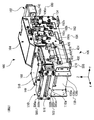
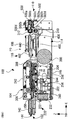
本第1実施形態に係るカード処理装置100は、図1〜図6に示すように、第1カード挿入口102aを有する第1挿入部102と、第1挿入部102の後方に連続して配置された搬送部104と、搬送部104の後方に連続して配置された振分部106と、振分部106の後方に連続して配置された、第2カード挿入口110aを有する第2挿入部110とを備えて構成されている。振分部106の上方には、ICデータ読取書込部108が配置されている。搬送部104と振分部106の右側面には、搬送部104を駆動する搬送機構112が設けられている。
(Overall configuration of card processing device)
As shown in FIGS. 1 to 6, the card processing apparatus 100 according to the first embodiment is continuously arranged behind the first insertion part 102 having the first card insertion slot 102a and the first insertion part 102. The second insertion slot having the second card insertion slot 110a continuously arranged behind the sorting section 106 and the sorting section 106 continuously arranged behind the sorting section 106. Unit 110. An IC data reading / writing unit 108 is disposed above the allocating unit 106. A transport mechanism 112 that drives the transport unit 104 is provided on the right side surfaces of the transport unit 104 and the sorting unit 106.

第1挿入部102は、カード120を、第1カード挿入口102aを介して、第1挿入部10の内部に取り込み、搬送部104に送る。カード120は、こうしてカード処理装置100の内部に取り込まれる。 First insertion portion 102, the card 120, via the first card insertion port 102a, the incorporation into the first insertion portion 10 2, and sends to the transport unit 104. The card 120 is thus taken into the card processing apparatus 100.

搬送部104は、第1カード挿入口102aを介して第1挿入部102の内部に取り込んだカード120を、搬送機構112の駆動力により、搬送部104の内部に形成された第1搬送路150(図7参照)に沿ってカード120を後方(または前方)に向けて搬送する。   The transport unit 104 uses a first transport path 150 formed inside the transport unit 104 by the driving force of the transport mechanism 112 for the card 120 taken into the first insert unit 102 via the first card insertion slot 102a. The card 120 is conveyed backward (or forward) along (see FIG. 7).

振分部106は、第1搬送路150と第2挿入部110との間を閉塞し、回収対象のカード120を回収口114(図8参照)に誘導する。   The sorting unit 106 closes the space between the first conveyance path 150 and the second insertion unit 110 and guides the card 120 to be collected to the collection port 114 (see FIG. 8).

第2挿入部110は、カード120を、第2カード挿入口110aを介して、第2挿入部110の内部に取り込み、振分部106に送る。カード120は、こうしてカード処理装置100の内部に取り込まれる。   The second insertion unit 110 takes the card 120 into the second insertion unit 110 via the second card insertion port 110 a and sends it to the distribution unit 106. The card 120 is thus taken into the card processing apparatus 100.

ここで、図1に示すように、X軸、Y軸及びZ軸を定義する。X軸は水平面内にあり、X軸方向はカード120の第1カード挿入口102aへの挿入方向であり、カード120の搬送方向でもある。X軸に沿って第1挿入部102から第2挿入部110に向かう方向を後方ともいい、その逆方向を前方ともいう。X軸は、図1では、左前から右奥に向かう方向に斜めに延在する。Y軸は、水平面内でX軸に直交しており、図1では、右前から左奥に向かう方向に斜めに延在する。Z軸は、水平面つまりX−Y平面に直交しており、上下方向に垂直に延在する。カード処理装置100は水平面上に配置されている。   Here, as shown in FIG. 1, an X axis, a Y axis, and a Z axis are defined. The X axis is in the horizontal plane, and the X axis direction is the insertion direction of the card 120 into the first card insertion slot 102a, and is also the transport direction of the card 120. The direction from the first insertion portion 102 toward the second insertion portion 110 along the X axis is also referred to as the rear, and the opposite direction is also referred to as the front. In FIG. 1, the X-axis extends obliquely in a direction from the left front toward the right back. The Y axis is orthogonal to the X axis in the horizontal plane, and in FIG. 1, the Y axis extends obliquely in a direction from the right front to the left back. The Z axis is orthogonal to the horizontal plane, that is, the XY plane, and extends vertically in the vertical direction. The card processing apparatus 100 is disposed on a horizontal plane.

また、カード120をX軸に沿って後方に搬送する際の回転方向、つまり、図3における時計回りの回転方向を、第1回転方向R1と定義し、カード120をX軸に沿って前方に搬送する際の回転方向、つまり、図3における反時計回りの回転方向を、第2回転方向R2とする。   Further, the rotation direction when the card 120 is conveyed rearward along the X axis, that is, the clockwise rotation direction in FIG. 3 is defined as a first rotation direction R1, and the card 120 is moved forward along the X axis. The rotation direction during conveyance, that is, the counterclockwise rotation direction in FIG. 3 is defined as a second rotation direction R2.

上記の構成要素から構成されるカード処理装置100は、図1〜図9に示されるように、X軸に沿って延在する一対の長辺とY軸に沿って延在する一対の短辺を有し、X−Y平面(水平面)に平行な断面形状が略矩形のフレーム130を備えている。つまり、カード処理装置100の第1挿入部102と、搬送部104、振分部106、第2挿入部110、ICデータ読取書込部108、搬送機構112は、フレーム130に沿って順に設けられている。   As shown in FIGS. 1 to 9, the card processing apparatus 100 including the above-described components includes a pair of long sides extending along the X axis and a pair of short sides extending along the Y axis. And a frame 130 having a substantially rectangular cross-sectional shape parallel to the XY plane (horizontal plane). That is, the first insertion unit 102, the conveyance unit 104, the distribution unit 106, the second insertion unit 110, the IC data reading / writing unit 108, and the conveyance mechanism 112 of the card processing apparatus 100 are sequentially provided along the frame 130. ing.

フレーム130は、一対の長辺のそれぞれを形成すると共に、所定の間隔で相対する第1および第2サイドプレート132、134を有している。また、フレーム130は、一対の短辺のそれぞれを形成すると共に、第1および第2サイドプレート132、134の一端側に固定された第1ステー136と、第1および第2サイドプレート132、134の他端側に固定された第2ステー138とを有している。   The frame 130 includes first and second side plates 132 and 134 that form a pair of long sides and face each other at a predetermined interval. The frame 130 forms a pair of short sides, a first stay 136 fixed to one end side of the first and second side plates 132 and 134, and the first and second side plates 132 and 134. The second stay 138 is fixed to the other end of the second stay 138.

第1ステー136は、相対する一対のフランジ部136a、136bと、それらフランジ部136a、136bの間を連結するウェブ部136cとを有している。一対のフランジ部136a、136bは、断面形状が略コの字形状を有しており、第1および第2サイドプレート132、134のそれぞれにネジなどによって固定されている。第2ステー138は、相対する一対のフランジ部138a、138bと、それらフランジ部138a、138bの間を連結するウェブ部138cとを有している。一対のフランジ部138a、138bは、断面形状が略コの字形状を有しており、第1および第2サイドプレート132、134のそれぞれにネジなどによって固定されている。第2ステー138の一対のフランジ部138a、138bのZ軸方向の長さは、ウェブ部138cのZ軸方向の幅より大きく形成されている。換言すれば、第2ステー138は、Y−Z平面視で略コの字形状に構成されている。   The first stay 136 includes a pair of opposed flange portions 136a and 136b, and a web portion 136c that connects between the flange portions 136a and 136b. The pair of flange portions 136a and 136b have a substantially U-shaped cross section, and are fixed to the first and second side plates 132 and 134 with screws or the like. The second stay 138 includes a pair of opposed flange portions 138a and 138b and a web portion 138c that connects the flange portions 138a and 138b. The pair of flange portions 138a and 138b have a substantially U-shaped cross section, and are fixed to the first and second side plates 132 and 134 with screws or the like. The length in the Z-axis direction of the pair of flange portions 138a and 138b of the second stay 138 is formed to be larger than the width in the Z-axis direction of the web portion 138c. In other words, the second stay 138 is configured in a substantially U shape in the YZ plan view.

フレーム130は、さらに、搬送部104の裏側(下側)に装着された矩形板状の第3ステー140と、第2ステー138の一対のフランジ部138a、138bの上部に配置された第4ステー148を有している。第4ステー148は、一対のフランジ部138a、138bを互いに連結している。   The frame 130 further includes a rectangular plate-like third stay 140 mounted on the back side (lower side) of the transport unit 104 and a fourth stay disposed above the pair of flange portions 138a and 138b of the second stay 138. 148. The fourth stay 148 connects the pair of flange portions 138a and 138b to each other.

第1ステー136の上方には、第1挿入部102が設けられており、第2ステー138の上方、すなわち、第2ステー138のウェブ部138cの上方には、第2挿入部110が設けられている。   A first insertion portion 102 is provided above the first stay 136, and a second insertion portion 110 is provided above the second stay 138, that is, above the web portion 138c of the second stay 138. ing.

第1挿入部102、搬送部104、振分部106および第2挿入部110は、フレーム130の長手方向(X軸方向)に沿ってこの順に配置されており、第1カード挿入口102a、後述される搬送部104の第1搬送路150、後述される振分部106の第2搬送路402および第2カード挿入口110aが略面一に連通して、カード処理装置100の内部に直線状の搬送経路118が形成されている。   The first insertion section 102, the transport section 104, the sorting section 106, and the second insertion section 110 are arranged in this order along the longitudinal direction (X-axis direction) of the frame 130, and the first card insertion slot 102a, which will be described later. The first transport path 150 of the transport section 104, the second transport path 402 of the sorting section 106, which will be described later, and the second card insertion slot 110a communicate with each other substantially in a straight line, and are linearly formed inside the card processing apparatus 100. The transport path 118 is formed.

第1サイドプレート132の第2サイドプレート134と反対側、換言すると、フレーム130の外側面(図1では右側の外側面)には、搬送経路118上のカード120を搬送する搬送機構112の駆動連結部326と、第1搬送路150と第2搬送路402との連結状態から第1搬送路150と振分部106の回収路404との連結状態に切り替える切替機構410とが配置されている。また、第2サイドプレート134の第1サイドプレート132と反対側、換言すると、フレーム130の外側面(図1では左側の外側面)には、搬送経路118上のカードを検出する第1、第2、第3及び第4カード検知部180、182、184、506と、振分部106の状態を検出する状態検知部424とが配置されている。第3ステー140の上面には、カード処理装置100を制御する制御部146が配置されている。   Driving the transport mechanism 112 that transports the card 120 on the transport path 118 on the opposite side of the first side plate 132 to the second side plate 134, in other words, on the outer surface of the frame 130 (the right outer surface in FIG. 1). A connecting unit 326 and a switching mechanism 410 that switches from a connected state of the first transport path 150 and the second transport path 402 to a connected state of the first transport path 150 and the collection path 404 of the sorting unit 106 are disposed. . In addition, on the opposite side of the second side plate 134 to the first side plate 132, in other words, on the outer side surface of the frame 130 (the outer side surface on the left side in FIG. 1), 2, the 3rd and 4th card | curd detection parts 180,182,184,506 and the state detection part 424 which detects the state of the distribution part 106 are arrange | positioned. A control unit 146 that controls the card processing device 100 is disposed on the upper surface of the third stay 140.

(第1挿入部)
次に、第1挿入部102について図1および図3〜図9を参照して詳細に説明する。
(First insertion part)
Next, the first insertion portion 102 will be described in detail with reference to FIGS. 1 and 3 to 9.

第1挿入部102は、第1カード挿入口102aを介してカード120を受け入れると共に、搬送部104に向けてカード120を案内する機能を有している。本第1実施形態の第1挿入部102は、平面視凸字形状の角柱142から形成されており、フレーム130に螺着されている。角柱142の内部には、平面視凸字形状の突出方向(X軸)に沿って貫通孔144が形成されており、貫通孔144は、角柱142の先端部に形成された第1カード挿入口102aと連通している。貫通孔144は、X軸と垂直な平面(Y−Z平面)に平行な断面の形状が略矩形状である。貫通孔144の幅は、カード120の一対の短辺の長さよりわずかに大きくされ、その厚みはカード120の厚みよりわずかに大きく且つカード120の2枚分の厚みより小さく形成されている。第1カード挿入口102aは、貫通孔144より一回り大きい。第1カード挿入口102aに挿入されたカードは、貫通孔144を通って、貫通孔144の内壁に案内されながら、搬送部104に送られる。   The first insertion unit 102 has a function of receiving the card 120 through the first card insertion slot 102 a and guiding the card 120 toward the transport unit 104. The first insertion portion 102 of the first embodiment is formed of a prismatic prism 142 having a convex shape in plan view, and is screwed to the frame 130. A through-hole 144 is formed inside the rectangular column 142 along the protruding direction (X axis) of the convex shape in plan view, and the through-hole 144 is a first card insertion slot formed at the tip of the rectangular column 142. 102a. The through hole 144 has a substantially rectangular cross-sectional shape parallel to a plane (YZ plane) perpendicular to the X axis. The width of the through hole 144 is slightly larger than the length of the pair of short sides of the card 120, and the thickness thereof is slightly larger than the thickness of the card 120 and smaller than the thickness of two cards 120. The first card insertion slot 102a is slightly larger than the through hole 144. The card inserted into the first card insertion slot 102 a passes through the through hole 144 and is sent to the transport unit 104 while being guided by the inner wall of the through hole 144.

なお、第1挿入部102の形状は、ここで述べたものに限定されない。円柱形状などの角柱以外の外形を有していても構わないし、角柱142を設けずにフレーム130の前端部に直接、貫通孔144を形成するだけでも構わない。その場合、貫通孔144の先端が第1カード挿入口102となる。第1挿入部102の形状及び構成は、用途に応じて適宜変更できることは言うまでもない。 In addition, the shape of the 1st insertion part 102 is not limited to what was described here. It may have an outer shape other than a prismatic shape such as a cylindrical shape, or the through hole 144 may be formed directly in the front end portion of the frame 130 without providing the prismatic prism 142. In that case, the tip of the through hole 144 is the first card slot 102 a. It goes without saying that the shape and configuration of the first insertion portion 102 can be appropriately changed according to the application.

(シャッタ機構)
シャッタ機構220は、図8〜図10に示すように、第1挿入部102と搬送部104との間に、より詳細には、第1挿入部102の貫通孔144と、後述される搬送部104の第1搬送路150との間に設けられており、カード120が第1挿入部102から第1搬送路150に移送されるのを規制する機能を有している。
(Shutter mechanism)
As shown in FIGS. 8 to 10, the shutter mechanism 220 is provided between the first insertion portion 102 and the conveyance portion 104, more specifically, a through hole 144 of the first insertion portion 102 and a conveyance portion described later. 104 is provided between the first conveyance path 150 and the card 120 and has a function of restricting the card 120 from being transferred from the first insertion portion 102 to the first conveyance path 150.

シャッタ機構220は、第1搬送路150と第1カード挿入102との連通を遮断する第1位置P1(図9参照)と、第1搬送路150と第1カード挿入口102を連通させる第2位置P2(図10参照)との間で、回動可能に構成されたシャッタ222と、シャッタ222を駆動(回動)する第1ソレノイド232と、第1ソレノイド232の駆動力をシャッタ222に伝達させる可動軸230とを有している。 The shutter mechanism 220, communicates with the first position P1 for blocking the first conveying path 150 communicating with the first card slot 102 a (see FIG. 9), the first transport path 150 of the first card slot 102 a The shutter 222 configured to be rotatable with respect to the second position P2 (see FIG. 10) , the first solenoid 232 that drives (rotates) the shutter 222, and the driving force of the first solenoid 232 is the shutter. And a movable shaft 230 to be transmitted to 222.

第1ソレノイド232は、図10(b)に示すように、第1ステー136の第1サイドプレート132側で、フレーム130の内側に、ブラケットを介して固定されている、第1ソレノイド232のプランジャ232aには、可動軸230の一端が固定されている。   As shown in FIG. 10B, the first solenoid 232 is a plunger of the first solenoid 232 that is fixed to the inside of the frame 130 via a bracket on the first side plate 132 side of the first stay 136. One end of the movable shaft 230 is fixed to 232a.

シャッタ222は、略凸字形状に形成された規制部224と、規制部224の凸部の両端から略直角に突出する一対の連結部226a、226bとから構成されている。一対の連結部226a、226bには、相対する位置に一対の貫通孔が形成されており、第1および第2サイドプレート132、134に固定された回動軸228がそれら貫通孔に挿入されていて、シャッタ222が回動軸228を中心に回動するように構成されている。第1サイドプレート132側の連結部226aには、前記貫通孔と規制部224との間に楕円形の貫通孔が形成されており、その楕円形の貫通孔には、プランジャ232aに係止された可動軸230の一端が挿入されていて、第1ソレノイド232の駆動力がシャッタ222に伝達されるようになっている。   The shutter 222 includes a restricting portion 224 formed in a substantially convex shape, and a pair of connecting portions 226a and 226b that project substantially perpendicularly from both ends of the convex portion of the restricting portion 224. The pair of connecting portions 226a and 226b are formed with a pair of through holes at opposing positions, and a rotating shaft 228 fixed to the first and second side plates 132 and 134 is inserted into the through holes. Thus, the shutter 222 is configured to rotate about the rotation shaft 228. The coupling part 226a on the first side plate 132 side has an elliptical through hole formed between the through hole and the restricting part 224. The elliptical through hole is engaged with the plunger 232a. One end of the movable shaft 230 is inserted, and the driving force of the first solenoid 232 is transmitted to the shutter 222.

シャッタ222は、常時、第1位置P1に保持されている。したがって、第1搬送路150と第1挿入部102との連通は、常時、遮断されていて、カード120が第1搬送路150に送出されないようになっている。外部装置1からカード処理装置100にシャッタ222の開放指示が出力されると、カード処理装置100の制御部146から第1ソレノイド232の駆動制御信号が出力される。第1ソレノイド232は、その駆動制御信号に応答して駆動され、シャッタ222が第2位置P2に移動される。こうして、第1搬送路150と第1カード挿入口102が連通し、カード120が第1搬送路150に送出可能となる。 The shutter 222 is always held at the first position P1. Therefore, the communication between the first transport path 150 and the first insertion portion 102 is always blocked, and the card 120 is not sent out to the first transport path 150. When an instruction to open the shutter 222 is output from the external device 1 to the card processing device 100, a drive control signal for the first solenoid 232 is output from the control unit 146 of the card processing device 100. The first solenoid 232 is driven in response to the drive control signal, and the shutter 222 is moved to the second position P2. In this way, the first conveyance path 150 and the first card insertion slot 102 a communicate with each other, and the card 120 can be sent to the first conveyance path 150.

本実施形態では、第1ソレノイド232として、一般的なプルソレノイドが採用されているため、第1ソレノイド232が励起されると、プランジャ232aが第1ソレノイド232の内部に吸引され、シャッタ222が第1位置P1から第2位置P2に向かって回動する。これによって、第1カード挿入口102と第1搬送路150が連通する。これに対し、第1ソレノイド232が消磁されると、プランジャ232aが第1ソレノイド232の内部から突出し、シャッタ222が第2位置P2から第1位置P1に向かって回動する。これによって、第1カード挿入口102と第1搬送路150の連通が遮断される。 In the present embodiment, since a general pull solenoid is employed as the first solenoid 232, when the first solenoid 232 is excited, the plunger 232a is sucked into the first solenoid 232 and the shutter 222 is moved to the first solenoid 232. It rotates from the first position P1 toward the second position P2. Accordingly, the first card slot 102 a and the first transport path 150 is communicated. On the other hand, when the first solenoid 232 is demagnetized, the plunger 232a protrudes from the inside of the first solenoid 232, and the shutter 222 rotates from the second position P2 toward the first position P1. Thereby, communication of the first card slot 102 a and the first transport path 150 is blocked.

なお、本実施形態では、第1ソレノイド232としてプルソレノイドを用いているが、シャッタ機構220の駆動源はこれに限定されるものではなく、プッシュソレノイド、ロータリーソレノイド、モータなどを用いても構わない。   In this embodiment, a pull solenoid is used as the first solenoid 232, but the drive source of the shutter mechanism 220 is not limited to this, and a push solenoid, a rotary solenoid, a motor, or the like may be used. .

(搬送部)
次に、搬送部104について、図1〜図13を参照しながら詳細に説明する。
(Transport section)
Next, the conveyance unit 104 will be described in detail with reference to FIGS.

搬送部104は、カード120を前後方向(X軸に沿って)搬送する機能と、カード120に形成された磁気ストライプに記憶された磁気データを読み取り、その磁気ストライプにデータを書き込む機能とを有している。   The transport unit 104 has a function of transporting the card 120 in the front-rear direction (along the X-axis) and a function of reading magnetic data stored in the magnetic stripe formed on the card 120 and writing data in the magnetic stripe. doing.

搬送部104は、磁気ヘッド244等が配置された第1ユニット240と、第1ユニット240の上部に配置された第2ユニット242とによって構成されている。第1および第2ユニット240、242との間には、カード120が通過可能な平板状の空隙が形成されており、その隙間が第1搬送路150として機能する。   The transport unit 104 includes a first unit 240 in which the magnetic head 244 and the like are disposed, and a second unit 242 disposed in the upper part of the first unit 240. A flat air gap through which the card 120 can pass is formed between the first and second units 240 and 242, and the gap functions as the first transport path 150.

第1搬送路150は、カード120が載置される底面152と、底面152に相対して配置された上面と、底面152のX軸に平行な一対の辺に設けられた第1および第2側壁156、158とによって形成され、Y−Z平面に平行な断面が第1挿入部102の貫通孔144と同様に、カード120の一対の短辺および厚みよりわずかに大きい略矩形状を有している。前記したとおり、第1搬送路150は、第1および第2ユニット240、242との間に形成されているので、第1搬送路150の底面152は第1ユニット240の上面に相当し、第1搬送路150の上面は第2ユニット242の下面に相当する。第1および第2側壁156、158のそれぞれが、第1ユニット240の上面と第2ユニット242の下面との間のスペーサとして機能することによって、第1および第2ユニット240、242の間に第1搬送路150が形成されている。   The first transport path 150 includes a bottom surface 152 on which the card 120 is placed, a top surface disposed to face the bottom surface 152, and first and second sides provided on a pair of sides parallel to the X axis of the bottom surface 152. The cross-section formed by the side walls 156 and 158 and having a cross section parallel to the YZ plane has a substantially rectangular shape slightly larger than the pair of short sides and the thickness of the card 120, like the through hole 144 of the first insertion portion 102. ing. As described above, since the first transport path 150 is formed between the first and second units 240 and 242, the bottom surface 152 of the first transport path 150 corresponds to the top surface of the first unit 240, and The upper surface of the first conveyance path 150 corresponds to the lower surface of the second unit 242. Each of the first and second side walls 156, 158 functions as a spacer between the upper surface of the first unit 240 and the lower surface of the second unit 242, thereby allowing the first and second units 240, 242 to One conveyance path 150 is formed.

第1搬送路150の底面152には、図7及び図10(a)に明瞭に示すように、磁気ヘッド244が配置される第1貫通孔160と、カード120を磁気ヘッド244と共に支持する支持部246が配置される第2貫通孔162と、搬送機構112の第1搬送ローラ装置302の一対のローラ302a、302bが配置される一対の第3貫通孔164a、164bと、第2搬送ローラ装置304の一対のローラ304a、304bが配置される一対の切欠172a、172bと、搬送経路118上のカード120を検出する第1〜第3カード検知部180、182、184が配置される第4〜第6貫通孔166、168、170とが形成されている。   As clearly shown in FIGS. 7 and 10A, the bottom surface 152 of the first transport path 150 has a first through hole 160 in which the magnetic head 244 is disposed and a support for supporting the card 120 together with the magnetic head 244. A second through hole 162 in which the portion 246 is disposed, a pair of third through holes 164a and 164b in which the pair of rollers 302a and 302b of the first transport roller device 302 of the transport mechanism 112 are disposed, and the second transport roller device A pair of notches 172a and 172b in which a pair of rollers 304a and 304b of 304 are disposed, and fourth to third in which first to third card detection units 180, 182 and 184 for detecting the card 120 on the transport path 118 are disposed. Sixth through holes 166, 168, and 170 are formed.

第1貫通孔160は、底面152のX軸方向の二つの辺の略中央で、第1側壁156から所定距離だけ離れた位置に、略矩形状に形成されている。より詳細には、第1貫通孔160は、第1搬送路150を搬送中のカード120の情報記憶部(例えば、一般的な磁気ストライプカードの磁気ストライプ)と相対する位置に形成されている。   The first through hole 160 is formed in a substantially rectangular shape at a position separated from the first side wall 156 by a predetermined distance at the approximate center of the two sides of the bottom surface 152 in the X-axis direction. More specifically, the first through-hole 160 is formed at a position facing an information storage unit (for example, a magnetic stripe of a general magnetic stripe card) of the card 120 being conveyed through the first conveyance path 150.

第2貫通孔162は、底面152のX軸方向の二つの辺の略中央で、第2側壁158から所定距離だけ離れた位置に、X軸に平行な一対の長辺を有する略矩形状として形成されている。第2貫通孔162は、X軸方向の位置に関しては、第1貫通孔160とほぼ同じ位置に形成されている。このように第2貫通孔162が形成されることによって、カード120が磁気ヘッド244と支持部246との両方で支持されるため、搬送中のカード120の情報記憶部(磁気ストライプ)に対する磁気データの読み取りおよび書き込みを行う際のカード120の姿勢が安定する。   The second through-hole 162 has a substantially rectangular shape having a pair of long sides parallel to the X axis at a position that is a predetermined distance from the second side wall 158 at the approximate center of the two sides of the bottom surface 152 in the X axis direction. Is formed. The second through hole 162 is formed at substantially the same position as the first through hole 160 with respect to the position in the X-axis direction. By forming the second through-hole 162 in this way, the card 120 is supported by both the magnetic head 244 and the support unit 246, and therefore magnetic data for the information storage unit (magnetic stripe) of the card 120 being conveyed. The posture of the card 120 when reading and writing is stabilized.

一対の第3貫通孔164a、164bは、底面152の第1挿入部102の側(上流側)の端部の近傍に形成されている。第3貫通孔164aは第1側壁156の側に、第3貫通孔164bは第2側壁158の側にあって、搬送中のカード120の情報記憶部(磁気ストライプ)に対面しないように形成されている。   The pair of third through holes 164a and 164b are formed in the vicinity of the end of the bottom surface 152 on the first insertion portion 102 side (upstream side). The third through hole 164a is on the first side wall 156 side and the third through hole 164b is on the second side wall 158 side so as not to face the information storage unit (magnetic stripe) of the card 120 being conveyed. ing.

一対の切欠172a、172bは、底面152の第1挿入部102とは反対側(すなわち第2カード挿入口110の側)の端部に形成されている。切欠172aは第1側壁156の側に、切欠172bは第2側壁158の側にあって、搬送中のカード120の情報記憶部(磁気ストライプ)に対面しないように形成されている。 A pair of notches 172a, 172 b are formed at the opposite end (i.e. the side of the second card slot 110 a) and the first insertion portion 102 of the bottom 152. The notch 172a is on the first side wall 156 side, and the notch 172b is on the second side wall 158 side, and is formed so as not to face the information storage unit (magnetic stripe) of the card 120 being conveyed.

一対の第3貫通孔164a、164bには、第1搬送ローラ装置302を構成する一対のローラ302a、302bが配置され、一対の切欠172a、172bには、第2搬送ローラ装置304を構成する一対のローラ304a、304bが配置されている。このため、第3貫通孔164a、164bや切欠172a、172bが、カード120の情報記憶部(磁気ストライプ)に対面せず、したがって、それらローラ302a、302b、304a、304bがカード120の情報記憶部に接触することがない。よって、カード120の情報記憶部の破損などを確実に防止することができる。   The pair of third through holes 164a and 164b are arranged with a pair of rollers 302a and 302b constituting the first conveying roller device 302, and the pair of notches 172a and 172b are a pair constituting the second conveying roller device 304. The rollers 304a and 304b are arranged. For this reason, the third through holes 164a, 164b and the notches 172a, 172b do not face the information storage unit (magnetic stripe) of the card 120. Therefore, the rollers 302a, 302b, 304a, 304b are the information storage unit of the card 120. There is no contact. Thus, damage to the information storage unit of the card 120 can be reliably prevented.

第4貫通孔166は、第2側壁158の、第3貫通孔164bより第1挿入部102の側にある端部の近傍に形成されている。第5および第6貫通孔168、170は、第3貫通孔164bと切欠172bとの間にこの順に形成されている。   The fourth through hole 166 is formed in the vicinity of the end portion of the second side wall 158 that is closer to the first insertion portion 102 than the third through hole 164b. The fifth and sixth through holes 168 and 170 are formed in this order between the third through hole 164b and the notch 172b.

第2側壁158には、第4〜第6貫通孔166、168、170に対応する位置に、それぞれ、第7〜第9貫通孔174、176、178が形成されている。第7〜第9貫通孔174、176、178には、詳細は後述される第1〜第3カード検知部180、182、184の第1〜第3ローラ186a、186b186cが、それぞれ配置されている。このため、第7〜第9貫通孔174、176、178のX軸に平行な一対の端縁の間の間隔が、第1〜第3ローラ186a、186b186cの厚み(X軸に平行な長さ)より大きく形成されている。また、第7〜第9貫通孔174、176、178の底面152に垂直な方向(Z軸方向)に延在する一対の端縁には、第7〜第9貫通孔174、176、178の一対の側縁の間の距離が、Y軸方向に第1搬送路150から遠ざかるにつれて、徐々に大きくなるようにテーパーが形成されている。こうすることで、第7〜第9貫通孔174、176、178の第1搬送路150に近い端部の間隔が、対応する第1〜第3ローラ186a、186b186cの直径より小さくされ、それによって、第1搬送路150より遠い位置にある端部の間隔が、対応する第1〜第3ローラ186a、186b186cの直径より大きくなるようにしている。 In the second side wall 158, seventh to ninth through holes 174, 176, and 178 are formed at positions corresponding to the fourth to sixth through holes 166, 168, and 170, respectively. The seventh to ninth through hole 174, 176, 178, first to third rollers 18 6a of the first to third card detection unit 180, 182, 184 The details will be described later, 1 86b, 186c, respectively Is arranged. Therefore, the spacing between the seventh to ninth pair of parallel edges in the X axis of the through-holes 174, 176, and 178 are first to third rollers 18 6a, 1 86b, the thickness of 186c (X-axis It is formed larger than (parallel length). Further, a pair of end edges extending in a direction (Z-axis direction) perpendicular to the bottom surface 152 of the seventh to ninth through holes 174, 176, 178 are formed on the seventh to ninth through holes 174, 176, 178. A taper is formed so that the distance between the pair of side edges gradually increases as the distance from the first conveyance path 150 increases in the Y-axis direction. In this way, the spacing of the end portion closer to the first transport path 150 of the seventh to ninth through hole 174, 176, and 178 is the corresponding first to third rollers 18 6a, 1 86b, smaller than the diameter of 186c Thus, the interval between the end portions located farther from the first conveyance path 150 is made larger than the diameters of the corresponding first to third rollers 18 6a , 1 86b and 186c .

なお、本実施形態のカード処理装置100では、第3貫通孔164bと第4貫通孔166と第5貫通孔168とが連結した1つの貫通孔として形成されているが、第3貫通孔164bと第4貫通孔166と第5貫通孔168は一体的に形成されてもよいし、個別に形成されてもよい。一対の切欠172a、172bは、第3貫通孔164a、164bのような貫通孔としても構わない。第3〜第6貫通孔164b、166、168、170および切欠172bを連結して、1つの貫通孔または切欠としても構わない。   In the card processing apparatus 100 of the present embodiment, the third through hole 164b, the fourth through hole 166, and the fifth through hole 168 are formed as one through hole, but the third through hole 164b and The fourth through hole 166 and the fifth through hole 168 may be formed integrally or individually. The pair of notches 172a and 172b may be through holes such as the third through holes 164a and 164b. The third to sixth through holes 164b, 166, 168, 170 and the notch 172b may be connected to form one through hole or notch.

磁気ヘッド244は、第1搬送路150を搬送されるカード120の情報記憶部つまり磁気ストライプに記憶された磁気データを読み取り、また、同磁気ストライプにデータを書き込む機能を有する。磁気ヘッド244は、図12に示すように、板バネ248の略中央に配置されていると共に、第1搬送路150の底面152の裏側(下側)から第1貫通孔160に挿入されている。板バネ248は、その両端が第1搬送路150の底面152の裏側に固定されている。磁気ヘッド244は、板バネ248によって底面152の表側、すなわち第1搬送路150の内部に向かって付勢されている。したがって、磁気ヘッド244は、カード120の動きに追従して、底面152に垂直な方向(Z軸方向)に揺動可能である。なお、ここでは、板バネ248は、固定具250を介して底面152の裏側に配置されているが、底面152に直接固定してもよい。   The magnetic head 244 has a function of reading magnetic data stored in an information storage unit, that is, a magnetic stripe, of the card 120 conveyed through the first conveyance path 150 and writing data in the magnetic stripe. As shown in FIG. 12, the magnetic head 244 is disposed substantially at the center of the leaf spring 248 and is inserted into the first through hole 160 from the back side (lower side) of the bottom surface 152 of the first transport path 150. . Both ends of the leaf spring 248 are fixed to the back side of the bottom surface 152 of the first conveyance path 150. The magnetic head 244 is urged toward the front side of the bottom surface 152 by the plate spring 248, that is, toward the inside of the first conveyance path 150. Therefore, the magnetic head 244 can follow the movement of the card 120 and can swing in a direction perpendicular to the bottom surface 152 (Z-axis direction). Here, the leaf spring 248 is disposed on the back side of the bottom surface 152 via the fixture 250, but may be directly fixed to the bottom surface 152.

支持部246は、図7に示すように、磁気ヘッド244と協働して、第1搬送路150を搬送されるカード120の姿勢を保持する機能を有している。支持部246は、平面視矩形状の平板部252と、平板部252の中央から突出した平面視矩形状の突出部254とを有している。突出部254は、第2貫通孔162に底面152の裏側から挿入され、磁気ヘッド244の底面152の表面からの突出量と、突出部254の底面152の表面からの突出量とが、ほぼ同じになるようにしている。突出部254の上面には、X軸方向に沿った両端部に傾斜面が形成されており、それら傾斜面の各端部が底面152の裏側にまで延在している。このように構成することによって、搬送中のカード120を、突出部254のX軸方向の二つの端部に引っかかることなく、底面152から突出部254に滑らかに移動させることが可能となる。   As shown in FIG. 7, the support unit 246 has a function of maintaining the posture of the card 120 conveyed through the first conveyance path 150 in cooperation with the magnetic head 244. The support portion 246 includes a flat plate portion 252 having a rectangular shape in plan view and a protruding portion 254 having a rectangular shape in plan view protruding from the center of the flat plate portion 252. The protruding portion 254 is inserted into the second through-hole 162 from the back side of the bottom surface 152, and the protruding amount from the surface of the bottom surface 152 of the magnetic head 244 is substantially the same as the protruding amount from the surface of the bottom surface 152 of the protruding portion 254. It is trying to become. On the upper surface of the projecting portion 254, inclined surfaces are formed at both ends along the X-axis direction, and each end portion of the inclined surfaces extends to the back side of the bottom surface 152. With this configuration, the card 120 being transported can be smoothly moved from the bottom surface 152 to the projecting portion 254 without being caught by the two end portions of the projecting portion 254 in the X-axis direction.

支持部246の下方には、底面152に固定された固定具258が配置されている(図8、図9参照)。平板部252と相対して配置された固定具258の平面部には、平板部252の反対側から一対のネジが挿入されており、それらネジにはバネ256がそれぞれ嵌装されている。バネ256は、一端が固定具258の平面部に当接し、他端が平板部252の裏側に当接していて、支持部246を底面152の表側(第1搬送路150)に向かって付勢している。したがって、磁気ヘッド244と同様に、支持部246も、搬送中のカード120に追従して、Z軸方向(上下方向)に揺動する。   A fixing tool 258 fixed to the bottom surface 152 is disposed below the support portion 246 (see FIGS. 8 and 9). A pair of screws are inserted from the opposite side of the flat plate portion 252 into the flat portion of the fixture 258 disposed opposite to the flat plate portion 252, and springs 256 are respectively fitted to these screws. One end of the spring 256 is in contact with the flat surface portion of the fixture 258, and the other end is in contact with the back side of the flat plate portion 252, and the support portion 246 is urged toward the front side (first conveyance path 150) of the bottom surface 152. doing. Accordingly, like the magnetic head 244, the support portion 246 also swings in the Z-axis direction (vertical direction) following the card 120 being conveyed.

本実施形態のカード処理装置100では、固定具258の平面部に挿入された一対のネジにバネ256がそれぞれ挿入されているが、固定具258に一対のバネを挿入する軸を形成しても構わない。また、支持部246を付勢するバネは1個でも構わないし、3個以上用いても構わない。さらに、支持部246を付勢するバネ256にコイルバネが用いられているが、磁気ヘッド244と同様に板バネでも構わない。   In the card processing apparatus 100 of the present embodiment, the springs 256 are respectively inserted into the pair of screws inserted into the flat portion of the fixture 258. However, even if the shaft for inserting the pair of springs is formed in the fixture 258, I do not care. The number of springs that urge the support portion 246 may be one, or three or more. Further, although a coil spring is used for the spring 256 that biases the support portion 246, a plate spring may be used similarly to the magnetic head 244.

次に、第1、第2及び第3カード検知部180、182、184について、図2、図4、図7、図10、図11および図23を参照しながら詳細に説明する。   Next, the first, second, and third card detectors 180, 182, and 184 will be described in detail with reference to FIGS. 2, 4, 7, 10, 11, and 23. FIG.

第2サイドプレート134には、第2側壁158の第7〜第9貫通孔174、176、178のそれぞれと対応する位置に、それぞれ、貫通孔(図示せず)が形成されている。したがって、第2側壁158の第7〜第9貫通孔174、176、178は、いずれも、第2サイドプレート134の貫通孔を介して、第2サイドプレート134(カード処理装置100)の外部に開口していることになる。第7〜第9貫通孔174、176、178に、それぞれ、第1〜第3カード検知部180、182、184が配置されている。   In the second side plate 134, through holes (not shown) are formed at positions corresponding to the seventh to ninth through holes 174, 176, and 178 of the second side wall 158, respectively. Accordingly, the seventh to ninth through holes 174, 176, and 178 of the second side wall 158 are all outside the second side plate 134 (card processing apparatus 100) via the through holes of the second side plate 134. It will be open. First to third card detection units 180, 182, and 184 are disposed in the seventh to ninth through holes 174, 176, and 178, respectively.

第1カード検知部180は、図2、図7及び図13に明瞭に示すように、Z軸に平行な回転軸線周りを回転可能であると共に、カード120に押動されてY軸に沿って(カード120の搬送方向に対して直交する方向に)揺動可能に構成されたローラ186aと、ローラ186aを回転可能に保持すると共に、ローラ186aを第1搬送路150の内部に向かって付勢する回転軸と、ローラ186aのY軸方向(カード120の搬送方向に対して直交する方向)への揺動を検出して、第1搬送路150内のカード120の有無を検出するセンサ190aとを有している。   As clearly shown in FIGS. 2, 7, and 13, the first card detection unit 180 can rotate around a rotation axis parallel to the Z axis and is pushed by the card 120 along the Y axis. The roller 186a configured to be swingable (in a direction orthogonal to the card 120 conveyance direction) and the roller 186a are rotatably held, and the roller 186a is urged toward the inside of the first conveyance path 150. And a sensor 190a that detects the presence or absence of the card 120 in the first transport path 150 by detecting the swing of the roller 186a in the Y-axis direction (direction orthogonal to the transport direction of the card 120). have.

ローラ186aは、円板状または円筒状の回転体から構成され、上面および下面の円形面の中心に軸孔188aを有している。軸孔188aには、ローラ186aの前記回転軸としての線バネ196aの第1軸198aが挿入されており、第1軸198aを中心として回転可能である。線バネ196aは、第1軸198aと第2軸200aによって略L字形状に形成されている。第1軸198aはZ軸方向に延在すると共に、第1貫通孔174のX軸の中央に配置されており、第2軸200aは第2サイドプレート134にネジなどによって固定されている。ローラ186aは、第7貫通孔174に配置されると共に、線バネ196aによって第1搬送路150に向かって付勢され、第1搬送路150の内部に対して進退可能に構成されている。待機位置P5aにあるローラ186aは、ローラ186aの側面と第1搬送路150の第1側壁156との間の最小間隔が、カード120の一対の短辺より小さくなるように構成されている。   The roller 186a is composed of a disk-shaped or cylindrical rotating body, and has a shaft hole 188a at the center of the upper and lower circular surfaces. A first shaft 198a of a wire spring 196a serving as the rotation shaft of the roller 186a is inserted into the shaft hole 188a, and is rotatable about the first shaft 198a. The wire spring 196a is formed in a substantially L shape by the first shaft 198a and the second shaft 200a. The first shaft 198a extends in the Z-axis direction and is disposed at the center of the X-axis of the first through hole 174. The second shaft 200a is fixed to the second side plate 134 with screws or the like. The roller 186a is disposed in the seventh through-hole 174 and is urged toward the first transport path 150 by the wire spring 196a so as to be able to advance and retreat with respect to the inside of the first transport path 150. The roller 186a at the standby position P5a is configured such that the minimum distance between the side surface of the roller 186a and the first side wall 156 of the first transport path 150 is smaller than the pair of short sides of the card 120.

センサ190aは、溝部192aを有する略コの字状の箱体の先端に互いに相対するように投光器と受光器とが配置された、溝型の透過型フォトセンサである。センサ190aは、第2サイドプレート134の第1搬送路150とは反対側(つまり外側)で第7貫通孔174に対応して設けられたブラケットを介して、第2サイドプレート134に固定されている。センサ190aは、その投光器から受光器に照射される光の光軸がZ軸に平行であり、溝部192aにローラ186aが進退可能に配置されている。 The sensor 190a is a groove-type transmission type photosensor in which a light projector and a light receiver are arranged so as to face each other at the tip of a substantially U-shaped box having a groove 192a. The sensor 190a is fixed to the second side plate 134 via a bracket provided corresponding to the seventh through hole 174 on the opposite side (that is, outside) of the second side plate 134 to the first conveyance path 150. Yes. In the sensor 190a, the optical axis of light emitted from the light projector to the light receiver is parallel to the Z axis, and a roller 186a is disposed in the groove 192a so as to be able to advance and retreat.

ローラ186aが線バネ196aの付勢力によって待機位置P5aに保持されている場合、ローラ186aは、第1搬送路150に進入すると共にセンサ190aの溝部192aから退出し、センサ190aの光軸を遮蔽しない。一方、ローラ186aが線バネ196aの付勢力に逆らって移動位置P6aに移動した場合、ローラ186aは、第1搬送路150から退出すると共にセンサ190aの溝部192aに進入し、センサ190aの光軸を遮蔽する。 When the roller 186a is held at the standby position P5a by the urging force of the wire spring 196a, the roller 186a enters the first conveyance path 150 and retreats from the groove 192a of the sensor 190a, and does not shield the optical axis of the sensor 190a. . On the other hand, when the roller 186a moves to the moving position P6a against the urging force of the wire spring 196a, the roller 186a retreats from the first conveyance path 150 and enters the groove portion 192a of the sensor 190a to change the optical axis of the sensor 190a. Shield.

ローラ186aの側面と第1搬送路150の第1側壁156との間の最小間隔は、カード120の一対の短辺より小さくなるように構成されているため、ローラ186aは、カード120の第2サイドプレート134側の側面と接触してY軸方向に変位し、待機位置P5aから移動位置P6aに向かって押動されて第1搬送路150から退出することができる。したがって、カード120が第1カード検知部180に達すると、ローラ186aは、カード120の側面によって待機位置P5aから移動位置P6aに向かって押動され、センサ190aの溝部192aに進入して光軸194aを遮光する。センサ190aは、ローラ186aによって光軸194aが遮光されると、第1検出信号SS1を出力する。制御部146に第1検出信号SS1が入力されると、第1カード検知部180でカード120が検出されたと判断される。すなわち、カード120は、ローラ186aを介してセンサ190aによって検出される。 Since the minimum distance between the side surface of the roller 186 a and the first side wall 156 of the first conveyance path 150 is configured to be smaller than the pair of short sides of the card 120, the roller 186 a is the second of the card 120. It contacts the side surface on the side plate 134 side and is displaced in the Y-axis direction, and is pushed out from the standby position P5a toward the movement position P6a and can exit from the first conveyance path 150. Therefore, when the card 120 reaches the first card detection unit 180, the roller 186a is pushed by the side surface of the card 120 from the standby position P5a toward the movement position P6a, and enters the groove 192a of the sensor 190a to enter the optical axis 194a. Shield from light. The sensor 190a outputs a first detection signal SS1 when the optical axis 194a is shielded by the roller 186a. When the first detection signal SS1 is input to the control unit 146, it is determined that the card 120 is detected by the first card detection unit 180. That is, the card 120 is detected by the sensor 190a through the roller 186a.

第2カード検知部182と第3カード検知部184は、第1カード検知部180と同様に構成されているため、第1カード検知部180と同じ構成要素には、第1カード検知部180のそれと同じ番号を付与し、アルファベットの添え字「b」および「c」で区別することにする。つまり、第1カード検知部180には「a」を付与しているから、第2カード検知部182には「b」を付与し、第3カード検知部184には「c」を付与して、三者を区別するのである。第2カード検知部182のローラ186bは第8貫通孔176に配置され、第3カード検知部184のローラ186cは第9貫通孔178に配置されている点で、第1カード検知部180とは異なっているが、その他の構成は第1カード検知部180と同様であるため、第2および第3カード検知部182、184についての詳細な説明は省略する。   Since the second card detection unit 182 and the third card detection unit 184 are configured in the same manner as the first card detection unit 180, the same components as the first card detection unit 180 include the first card detection unit 180. The same number is assigned, and the alphabetic suffixes “b” and “c” are used to distinguish them. That is, since “a” is given to the first card detection unit 180, “b” is given to the second card detection unit 182, and “c” is given to the third card detection unit 184. The three are distinguished. The roller 186 b of the second card detection unit 182 is disposed in the eighth through hole 176, and the roller 186 c of the third card detection unit 184 is disposed in the ninth through hole 178 and is different from the first card detection unit 180. Although different, the other configuration is the same as that of the first card detection unit 180, and thus detailed description of the second and third card detection units 182 and 184 is omitted.

第1〜第3カード検知部180、182、184のそれぞれは、カード120の側面で接触・押動されるローラ186a、186b、186cの移動(変位)をセンサ190a、190b、190cでそれぞれ検出することで、カード120の存在を検出する。したがって、カード120が全面にわたって透光性を有するようなスケルトンカードであっても、第1〜第3カード検知部180、182、184でカード120が検出できないという不具合は生じない。   Each of the first to third card detectors 180, 182, and 184 detects movement (displacement) of the rollers 186a, 186b, and 186c that are contacted and pushed on the side surface of the card 120 by the sensors 190a, 190b, and 190c, respectively. Thus, the presence of the card 120 is detected. Therefore, even if the card 120 is a skeleton card having translucency over the entire surface, there is no problem that the card 120 cannot be detected by the first to third card detection units 180, 182, and 184.

第1搬送路150の上面(第2ユニット242の下面)には、一対の第10貫通孔、一対の第11貫通孔、一対の第12貫通孔と、第13貫通孔が形成されている。一対の第10貫通孔は、それぞれ略矩形状を有し、底面152に形成された一対の第3貫通孔164a、164bに相対して形成されていて、それらの内部には第3搬送ローラ装置306の一対のローラ306a、306bが配置されている。一対の第11貫通孔は、それぞれ略矩形状を有し、底面152に形成された一対の切欠172a、172bに相対して形成されていて、その内部には一対の第4搬送ローラ装置308の一対のローラ308a、308bが配置されている。 A pair of tenth through holes, a pair of eleventh through holes, a pair of twelfth through holes, and a thirteenth through hole are formed on the upper surface of the first transport path 150 (the lower surface of the second unit 242). Each of the pair of tenth through holes has a substantially rectangular shape and is formed to be opposed to the pair of third through holes 164a and 164b formed in the bottom surface 152, and a third transport roller device is provided in the inside thereof. A pair of rollers 306a and 306b are disposed. Each of the pair of eleventh through holes has a substantially rectangular shape and is formed so as to be opposed to the pair of notches 172a and 172b formed in the bottom surface 152. Inside the pair of fourth transport roller devices 308, A pair of rollers 308a and 308b are arranged.

一対の第12貫通孔は、それぞれ略矩形状を有し、第1貫通孔160に相対して形成されている。一対の第12貫通孔には、一対の支持部が配置され、磁気ヘッド244と当該一対の支持部とによってカード120を挟持するようになっている。第13貫通孔は、略矩形状を有し、底面152に形成された第2貫通孔162に相対して形成されている。第13貫通孔には支持部が挿入され、当該支持部と共働してカード120を挟持するようになっている。 Each of the pair of twelfth through holes has a substantially rectangular shape and is formed to face the first through hole 160. The pair of the 12 holes, a pair of support portions are arranged, so as to sandwich the card 120 by the magnetic head 244 and the pair of support portions. The thirteenth through hole has a substantially rectangular shape and is formed opposite to the second through hole 162 formed in the bottom surface 152. A support part is inserted into the thirteenth through hole, and the card 120 is clamped in cooperation with the support part .

(振分部)
次に、振分部106について図1〜図10を参照して詳細に説明する。
(Sorting part)
Next, the distribution unit 106 will be described in detail with reference to FIGS.

振分部106は、第1搬送路150と第2挿入部110との間の通路を閉鎖して、回収対象のカード120を回収口114に誘導する機能を有している。振分部106は、第1搬送路150と第2挿入口110との間の通路を連通させる第3位置P3と、同通路を閉鎖する第4位置P4の間を往復動する振分部材400と、振分部材400が第3位置P3と第4位置P4のいずれに位置するかを検出する状態検知部424と、振分部材400を第3位置P3と第4位置P4の間で回動させる切替機構410とを有している。   The sorting unit 106 has a function of closing the passage between the first conveyance path 150 and the second insertion unit 110 and guiding the card 120 to be collected to the collection port 114. The distribution unit 106 reciprocates between a third position P3 where the passage between the first conveyance path 150 and the second insertion port 110 is communicated and a fourth position P4 where the passage is closed. A state detection unit 424 that detects whether the distribution member 400 is located at the third position P3 or the fourth position P4, and the distribution member 400 is rotated between the third position P3 and the fourth position P4. And a switching mechanism 410 to be operated.

以下の説明では、各々の方向(つまりX軸、Y軸、Z軸)は、振分部材400が第3位置P3に位置する場合を基準とする。   In the following description, each direction (that is, the X axis, the Y axis, and the Z axis) is based on the case where the sorting member 400 is located at the third position P3.

振分部材400は、Y−Z平面に平行な断面形状が略H字形状を有しており、X軸方向に延在する一対の長辺を持つ一対の側壁と当該一対の側壁の間を連結するウェブとを備えている。振分部材400の一対の側壁の後方の端部(第1搬送路150とは反対側の端部)は、後述される搬送機構112の第5搬送ローラ装置310の第5回転軸322に回転可能に固定されており、振分部材400が第5回転軸322を中心として第3位置P3と第4位置P4との間を回動可能になっている。 Sorting member 400, Y-Z parallel cross section to the plane has a substantially H-shape, a pair of side walls having a pair of long sides extending in the X-axis direction, the pair of side walls and a web Bed for connecting the. Rear ends of the pair of side walls of the distribution member 400 (the end opposite to the first conveying path 150), the fifth rotation shaft 322 of the fifth transport rollers 310 of the transport mechanism 112 to be described later The distribution member 400 is fixed so as to be rotatable, and the distribution member 400 is rotatable between the third position P3 and the fourth position P4 about the fifth rotation shaft 322.

振分部材400のウェブの表面側には、カード120をX軸に沿って搬送する第2搬送路402が構成されている。第2搬送路402は、第1搬送路150と同様に、Y−Z平面に平行な断面(垂直断面)の形状が、カード120の一対の短辺と厚みよりもわずかに大きい略矩形状を有している。第2搬送路402の底面は振分部材400のウェブによって形成されている。第2搬送路402の一対の側面は振分部材400のウェブの表面側の一対の側壁によって形成されている。さらに、底面402aの上方には、底面402aに平行な上面が配置されている。振分部材400が第3位置P3に位置する時、第2搬送路402の底面402aは、第1搬送路150の底面152を略面一になるように構成されている。こうして、X軸に沿って搬送されるカード120が、第1搬送路150と第2搬送路402との間を滑らかに移動できるようにしている。 On the surface side of the web blanking the distribution member 400, second conveying path 402 for conveying along the card 120 in the X-axis is configured. Similar to the first transport path 150, the second transport path 402 has a substantially rectangular shape in which the cross section (vertical cross section) parallel to the YZ plane is slightly larger than the pair of short sides and the thickness of the card 120. Have. Bottom surface of the second transport path 402 is thus formed on the web blanking sorting member 400. A pair of side surfaces of the second transport path 402 is thus formed on the pair of side wall surface side of the web blanking of the sorting member 400. Furthermore, above the bottom surface 402a, it is disposed on surfaces parallel to the bottom surface 402a. When the sorting member 400 is located at the third position P3, the bottom surface 402a of the second transport path 402 is configured to be substantially flush with the bottom surface 152 of the first transport path 150. In this way, the card 120 transported along the X axis can move smoothly between the first transport path 150 and the second transport path 402.

第2搬送路402の上面には、カード120に搭載された非接触式のICチップ124のICデータの読み込みと書き込みを行うアンテナ440が配置されている。アンテナ440は、X軸に沿ったICチップの軌跡上に配置され、カード120が第1および第2搬送路150、402をX軸に沿って搬送され、ICチップがアンテナ440に到達した時に、制御部146から出力されるICデータ読取制御信号IDRに基づいてICチップからICデータを読み取り、ICデータ書込制御信号IDWに基づいてICチップにデータを書き込む。 The upper surface of the second transport path 402, an antenna 440 for reading and writing of IC data IC chip 124 of the non-contact mounted on the card 120 are disposed. The antenna 440 is arranged on the locus of the IC chip along the X axis, and when the card 120 is conveyed along the X axis along the first and second conveyance paths 150 and 402, and the IC chip reaches the antenna 440, The IC data is read from the IC chip based on the IC data read control signal IDR output from the control unit 146, and the data is written to the IC chip based on the IC data write control signal IDW.

振分部材400のウェブの裏面側には、カード120を回収口114に案内する回収路404が形成されている。振分部材400のウェブの裏面には、その第2挿入部110の側の端部に、回収口114に向かって突出して形成された一対の案内部材406が形成されている。一対の案内部材406は、第1搬送路150の側の端面が、凹状の曲面もしくは傾斜面に形成されている。これにより、第1搬送路150から回収路404に誘導されたカード120の搬送方向の先端部が、案内部材406の端面に当接すると共に、当該面の表面に沿って回収口114に向かって案内される。 On the back side of the web blanking of sorting member 400, the recovery passage 404 for guiding the card 120 to the recovery port 114 is formed. The rear surface of the web blanking sorting member 400, the end on the side of the second insertion portion 110, a pair of guide members 406 that protrudes toward the recovery port 114 is formed. In the pair of guide members 406, end surfaces on the first conveyance path 150 side are formed as concave curved surfaces or inclined surfaces. Thus, the distal end portion of the conveying direction of the card 120 induced recovery path 404 from the first transport path 150, abuts against the end face of the guide member 406, toward the recovery port 114 along the surface of the end face To be guided.

フレーム130の第1サイドプレート132の側には、図3に示すように、振分部材400を第3位置P3と第4位置P4との間で回動させる切替機構410が配置されている。切替機構410は、駆動源である第2ソレノイド412と、第2ソレノイド412に連結されたプッシュバー418と、プッシュバー418を介して伝達された第2ソレノイド412の駆動力を振分部材400に伝達するリンク部材420と、振分部材400に設けられ且つリンク部材420に連結された被動部材422とを有している。   As shown in FIG. 3, a switching mechanism 410 that rotates the sorting member 400 between the third position P3 and the fourth position P4 is disposed on the first side plate 132 side of the frame. The switching mechanism 410 has a second solenoid 412 as a driving source, a push bar 418 connected to the second solenoid 412, and the driving force of the second solenoid 412 transmitted via the push bar 418 to the sorting member 400. It has a link member 420 for transmission and a driven member 422 provided on the distribution member 400 and connected to the link member 420.

第2ソレノイド412は、コイル(図示されない)と固定鉄心(図示されない)が収納されたフレームと当該フレームに挿入されるプランジャ414と、プランジャ414をフレームから突出する方向に付勢するバネ416とを有している。第2ソレノイド412が励起されると、バネ416の付勢力に逆らってプランジャ414がフレームの内部に吸引される。第2ソレノイド412が消磁されると、バネ416の付勢力によってプランジャ414がフレームから押し出される。このように、第2ソレノイド412としては、プランジャ414が往復駆動される、所謂プルソレノイドが用いられている。第2ソレノイド412は、プランジャ414がほぼX軸に沿って往復移動するように配置されると共に、ブラケットを介して第1サイドプレート132に固定されている。 The second solenoid 412 includes a coil (not shown) and a fixed iron core (not shown) and frames that have been stored, a plunger 414 that is inserted into the frame, urges the plunger 414 in the protruding direction frame or al And a spring 416. When the second solenoid 412 is energized, the plunger 414 against the biasing force of the spring 416 is sucked into the interior of the frame. When the second solenoid 412 is demagnetized, the plunger 414 by the biasing force of the spring 416 is pushed out frames or al. As described above, a so-called pull solenoid in which the plunger 414 is reciprocated is used as the second solenoid 412. The second solenoid 412 is disposed so that the plunger 414 reciprocates substantially along the X axis, and is fixed to the first side plate 132 via a bracket.

プッシュバー418は、略直線状の形状を有しており、プランジャ414が往復動する方向(ほぼX軸方向)に沿って配置されると共に、一方の端部がプランジャ414のフレームから突出している部分に連結されている。したがって、プッシュバー418は、プランジャ414の往復動に連動して、ほぼX軸に沿って往復動する。一方、プッシュバー418のプランジャ414が連結された側とは反対側の端部には、リンク部材420が連結されているので、第2ソレノイド412の駆動力がプッシュバー418を介してリンク部材420に伝達される。   The push bar 418 has a substantially linear shape, is disposed along the direction in which the plunger 414 reciprocates (substantially in the X-axis direction), and one end projects from the frame of the plunger 414. It is connected to the part. Therefore, the push bar 418 reciprocates substantially along the X axis in conjunction with the reciprocation of the plunger 414. On the other hand, since the link member 420 is connected to the end of the push bar 418 opposite to the side where the plunger 414 is connected, the driving force of the second solenoid 412 is transmitted via the push bar 418 to the link member 420. Is transmitted to.

リンク部材420は、ほぼ鈍角三角形の形状を有する板状部材で構成されており、内心部を中心に回動可能に第1サイドプレート132に係止されている。リンク部材420の鋭角を有する一対の頂点の一方の端部には、プッシュバー418が互いに回動可能に連結されている。リンク部材420の当該端部とは反対側の端部には、ローラが配置されており、振分部材400に設けられた被動部材422に連結されている。これによって、第2ソレノイド412の駆動力が、プッシュバー418とリンク部材420を介して被動部材422に伝達される。   The link member 420 is formed of a plate-like member having a substantially obtuse triangular shape, and is locked to the first side plate 132 so as to be rotatable about the inner center portion. A push bar 418 is rotatably connected to one end of a pair of apexes having an acute angle of the link member 420. A roller is disposed at the end of the link member 420 opposite to the end, and is connected to a driven member 422 provided in the sorting member 400. As a result, the driving force of the second solenoid 412 is transmitted to the driven member 422 via the push bar 418 and the link member 420.

被動部材422は、振分部材400の側壁の回収路404側の端部に設けられている。被動部材422は、断面形状が略L字形状を有していて、側壁からY軸に沿って突出する第1突出部と、第1突出部の側壁とは反対側の端部から第1突出部に対して直角にZ軸に沿って延在する第2突出部と、第2突出部に形成された貫通孔とを有している。貫通孔は、略「ヘ」の字状に形成され、その頂点が第2突出部の第1挿入部102の側に配置され、その後端部が頂点からX軸とZ軸に沿って配置されている。貫通孔には、リンク部材420のローラが挿入されていて、貫通孔の内部を往復動可能となっている。   The driven member 422 is provided at the end of the side wall of the sorting member 400 on the collection path 404 side. The driven member 422 has a substantially L-shaped cross section, a first protrusion protruding from the side wall along the Y axis, and a first protrusion from the end opposite to the side wall of the first protrusion. A second protrusion extending along the Z-axis at a right angle to the part, and a through hole formed in the second protrusion. The through-hole is formed in a substantially “f” shape, the apex thereof being disposed on the first insertion portion 102 side of the second protrusion, and the rear end thereof being disposed along the X axis and the Z axis from the apex. ing. The roller of the link member 420 is inserted into the through hole, and can reciprocate inside the through hole.

次に、振分部106の動作について詳細に説明する。   Next, the operation of the distribution unit 106 will be described in detail.

第2ソレノイド412が待機状態、つまり消磁されている場合、プランジャ414はバネ416の付勢力によってフレームから引き出されている。プッシュバー418は、プランジャ414によってX軸に沿って押動されると共に、リンク部材420の端部をX軸に沿って押動する。リンク部材420は、端部のX軸へ移動に伴い、内心を中心として第2回転方向R2に回転する。リンク部材420の第2回転方向R2への回転に伴い、端部が前方に向かって移動する。これに伴い、振分部材400は第3位置P3に移動する。   When the second solenoid 412 is in a standby state, that is, demagnetized, the plunger 414 is pulled out of the frame by the biasing force of the spring 416. The push bar 418 is pushed along the X axis by the plunger 414 and pushes the end of the link member 420 along the X axis. The link member 420 rotates in the second rotation direction R2 around the inner center as the end member moves to the X axis. As the link member 420 rotates in the second rotation direction R2, the end portion moves forward. Accordingly, the sorting member 400 moves to the third position P3.

第2ソレノイド412が励磁された場合、プランジャ414はバネ416の付勢力に逆らってフレーム内に吸引される。換言すれば、プランジャ414が前方に移動する。プランジャ414の移動に伴い、プッシュバー418が前方に移動すると共に、リンク部材420の端部が前方に向かって移動する。これに伴い、リンク部材420が第1回転方向R1に回転し、当該端部が後方に向かって移動する。当該端部の移動に伴い、振分部材400は第3位置P3から第4位置P4に移動する。   When the second solenoid 412 is excited, the plunger 414 is attracted into the frame against the urging force of the spring 416. In other words, the plunger 414 moves forward. As the plunger 414 moves, the push bar 418 moves forward and the end of the link member 420 moves forward. Accordingly, the link member 420 rotates in the first rotation direction R1, and the end portion moves rearward. As the end portion moves, the sorting member 400 moves from the third position P3 to the fourth position P4.

フレーム130の第2サイドプレート134側には、図4に示すように、振分部材400が第3位置および第4位置P3、P4のいずれに位置しているかを検出する状態検知部424が配置されている。状態検知部424は、一対の被検知部428、432と、一対の被検知部428、432のそれぞれを検出する一対のセンサ426、430とを有している。一対の被検知部428、432のそれぞれは、振分部材400の側壁からY軸に沿って突出する板状部材から構成されている。一対のセンサ426、430としては、略コの字状の箱体の先端に互いに相対するように投光器と受光器とが配置された、溝型の透過型フォトセンサが用いられている。一対のセンサ426、430は、第2サイドプレート134からY軸に沿って突出すると共に、X軸に延在するブラケットに固定されており、被検知部428に対応する位置にセンサ426が配置され、被検知部432に対応する位置にセンサ430が配置されている。   On the second side plate 134 side of the frame 130, as shown in FIG. 4, a state detection unit 424 that detects whether the sorting member 400 is located at the third position or the fourth position P3 or P4 is disposed. Has been. The state detection unit 424 includes a pair of detection units 428 and 432 and a pair of sensors 426 and 430 that detect the pair of detection units 428 and 432, respectively. Each of a pair of to-be-detected parts 428 and 432 is comprised from the plate-shaped member which protrudes from the side wall of the distribution member 400 along the Y-axis. As the pair of sensors 426 and 430, groove-type transmission type photosensors are used in which a projector and a light receiver are arranged so as to face each other at the ends of a substantially U-shaped box. The pair of sensors 426, 430 protrude from the second side plate 134 along the Y axis and are fixed to a bracket extending in the X axis, and the sensor 426 is disposed at a position corresponding to the detected portion 428. The sensor 430 is disposed at a position corresponding to the detected part 432.

振分部材400が第3位置P3に位置する場合、一対の被検知部428、432は、それぞれ、一対のセンサ426、430の溝部に挿入されるように構成されている。そのため、振分部材400が第3位置P3に位置する場合、一対のセンサ426、430のそれぞれの投光器から受光器への光軸が一対の被検知部428、432によって遮られ、その結果、一対のセンサ426、430の受光器が受光する受光量が減少する。一方、振分部材400が第4位置P4に位置する場合、一対の被検知部428、432のそれぞれは、一対のセンサ426、430の溝部から退出するように構成されている。そのため、振分部材400が第4位置P4に位置する場合、一対のセンサ426、430のそれぞれの投光器から受光器への光軸は一対の被検知部428、432によって遮られず、その結果、一対のセンサ426、430の受光器が受光する受光量は、振分部材400が第3位置P3に位置する場合よりも増加する。一対のセンサ426、430の受光器が受光する受光量の変化を検出することによって、振分部材400第3および第4位置P3、P4のいずれかに位置するかが検出される。 When the sorting member 400 is located at the third position P3, the pair of detected portions 428 and 432 are configured to be inserted into the groove portions of the pair of sensors 426 and 430, respectively. Therefore, when the distribution member 400 is located at the third position P3, the optical axes from the light projectors to the light receivers of the pair of sensors 426 and 430 are blocked by the pair of detected portions 428 and 432, respectively. The amount of light received by the light receivers of the sensors 426 and 430 decreases. On the other hand, when the sorting member 400 is located at the fourth position P4, each of the pair of detected portions 428 and 432 is configured to exit from the groove portion of the pair of sensors 426 and 430. Therefore, when the distribution member 400 is located at the fourth position P4, the optical axes from the light projectors to the light receivers of the pair of sensors 426 and 430 are not blocked by the pair of detected portions 428 and 432, respectively. The amount of light received by the light receivers of the pair of sensors 426 and 430 is greater than when the distribution member 400 is located at the third position P3. By detecting a change in the amount of light received by the light receivers of the pair of sensors 426 and 430, it is detected whether the sorting member 400 is located at any of the third and fourth positions P3 and P4.

(第2挿入部)
次に、第2挿入部110について、図1〜図10を参照して説明する。
(Second insertion part)
Next, the 2nd insertion part 110 is demonstrated with reference to FIGS.

第2挿入部110は、図2に明瞭に示すように、搬送経路118に対して第1挿入部102とは反対側の端部に設けられている。第2挿入部110は、複数枚のカード120を収納し、当該カード120を1枚ずつ払い出すカード払い出し機(図示されない)などに連通され、前記カード払い出し機から払い出されたカード120を搬送経路118に案内する機能を有している。   As clearly shown in FIG. 2, the second insertion portion 110 is provided at the end opposite to the first insertion portion 102 with respect to the transport path 118. The second insertion unit 110 stores a plurality of cards 120, communicates with a card dispenser (not shown) that dispenses the cards 120 one by one, and transports the cards 120 dispensed from the card dispenser A function of guiding to the route 118 is provided.

第2挿入部110は、第2ステー138の上部に配置されている。第2挿入部110は、カード120の厚みよりわずかに大きい間隔で相対して配置された第1部材500および第2部材502と、第2カード挿入口110aから挿入されたカード120を検出する第4カード検知部506とを有している。   The second insertion portion 110 is disposed on the second stay 138. The second insertion unit 110 detects the first member 500 and the second member 502 that are disposed opposite to each other with a slightly larger interval than the thickness of the card 120 and the card 120 inserted from the second card insertion port 110a. 4 card detector 506.

第1部材500は、略矩形状のステー部500aと、ステー部500aに対して垂直な関係を有すると共にステー部500aの一対の長辺と平行な一対の長辺を有する略矩形状の案内部500bと、ステー部500aの一対の長辺の一方と案内部500bの一対の長辺の一方とを接続するテーパー部500cと、案内部500bの他方の長辺から連続的に設けられたテーパー部500dとを有している。第2部材502は、第1部材500と同様の構成であり、ステー部502a、案内部502b及びテーパー部502c、502dを有している。第2部材502は、第1部材500の下方に配置され、第1部材500の案内部502bと第2部材502の案内部502bの間がカード120の厚みよりわずかに大きい間隔を有するように、案内部500bと案内部502bが互いに相対して配置されている。   The first member 500 has a substantially rectangular stay portion 500a and a substantially rectangular guide portion having a pair of long sides parallel to the pair of long sides of the stay portion 500a while having a perpendicular relationship to the stay portion 500a. 500b, a tapered portion 500c connecting one of the pair of long sides of the stay portion 500a and one of the pair of long sides of the guide portion 500b, and a tapered portion provided continuously from the other long side of the guide portion 500b 500d. The second member 502 has the same configuration as the first member 500, and includes a stay portion 502a, a guide portion 502b, and tapered portions 502c and 502d. The second member 502 is disposed below the first member 500 so that the gap between the guide portion 502b of the first member 500 and the guide portion 502b of the second member 502 is slightly larger than the thickness of the card 120. The guide part 500b and the guide part 502b are disposed opposite to each other.

第2ステー138のフランジ部138bには、案内部500bと案内部502bとの間に設けられた隙間518(図12参照)と略同じ高さに、矩形状の貫通孔が形成されている。当該貫通孔には、詳細は後述される第4カード検知部506のローラ508が配置されている。上記貫通孔は、X軸方向の長さがローラ508の直径より大きく、Z軸方向の長さがローラ508の厚みより大きく形成されている。 A rectangular through hole is formed in the flange portion 138b of the second stay 138 at substantially the same height as the gap 518 (see FIG. 12) provided between the guide portion 500b and the guide portion 502b. The roller 508 of the 4th card | curd detection part 506 mentioned later for details is arrange | positioned at the said through- hole . The through hole has a length in the X-axis direction larger than the diameter of the roller 508 and a length in the Z-axis direction larger than the thickness of the roller 508.

第4カード検知部506は、第1〜第3カード検知部180、182、184と基本的に同じ構成を有しており、ローラ508、センサ510およびねじりバネ516を備えて構成されている。ローラ508は、円盤状または円筒状の回転体から構成され、上面および下面の円形面の中心に軸孔を有している。当該孔には、ねじりバネ516の第1軸51aが挿入されていて、ローラ508は第1軸51aを中心として回転可能である。ねじりバネ516は、第1軸51aと第2軸51bとによって略L字形状に形成されており、第1軸51aはZ軸方向に延在し、第2軸51bは第4ステー148にネジなどによって固定されている。ローラ508は、貫通孔504に配置されると共にねじりバネ516によって隙間518に向かって付勢されており、第2挿入部110に対して進退可能に構成されている。待機位置P5dにあるローラ508は、ローラ508の側面と第2ステー138のフランジ138aとの間の最小間隔がカード120の一対の短辺より小さくなるように構成されている。 The fourth card detection unit 506 has basically the same configuration as the first to third card detection units 180, 182, and 184, and includes a roller 508, a sensor 510, and a torsion spring 516. Roller 508 is composed of a disc-shaped or cylindrical rotary member, it has a shaft hole at the center of the circular surface of the upper and lower surfaces. The said axial bore, the first shaft 51 6 a of the torsion spring 516 have been inserted, the roller 508 is rotatable about the first axis 51 6 a. The torsion spring 516 is formed in a substantially L shape by the first shaft 51 6 a and the second shaft 51 6 b, and the first shaft 51 6 a extends in the Z-axis direction, and the second shaft 51 6 b is fixed to the fourth stay 148 with screws or the like. The roller 508 is disposed in the through hole 504 and is urged toward the gap 518 by a torsion spring 516, and is configured to be able to advance and retreat relative to the second insertion portion 110. The roller 508 at the standby position P5d is configured such that the minimum distance between the side surface of the roller 508 and the flange portion 138a of the second stay 138 is smaller than the pair of short sides of the card 120.

センサ510としては、溝部512を有する略コの字状の箱体の先端に互いに相対するように投光器と受光器とが配置された、溝型の透過型フォトセンサが用いられている。センサ510は、第2カード挿入口110と反対側、つまり第2サイドプレート134の外側で、図示しない貫通孔に対応して設けられたブラケットを介して、第2ステー138のフランジ138bに固定されている。センサ510は、その投光器から受光器に照射される光の光軸がZ軸に平行であり、溝部512にはローラ508が進入可能に配置されている。センサ510は、常態ではローラ508によって光軸が遮断されず、ローラ508が第1搬送路150から退出すると、光軸が遮断されるように配置されている。 As the sensor 510, a groove-type transmission photosensor is used in which a projector and a light receiver are arranged so as to face each other at the tip of a substantially U-shaped box having a groove portion 512. Sensor 510, the second card slot 110 a opposite side, that is on the outside of the second side plate 134 via a bracket provided corresponding to the through hole (not shown), the flange portion 138b of the second stay 138 It is fixed. In the sensor 510, the optical axis of light emitted from the light projector to the light receiver is parallel to the Z axis, and a roller 508 is disposed in the groove portion 512 so as to be able to enter. The sensor 510 is arranged so that the optical axis is not interrupted by the roller 508 in a normal state, and the optical axis is interrupted when the roller 508 retreats from the first conveyance path 150.

前述したように、ローラ508の側面と第2ステー138のフランジ138aとの最小間隔は、カード120の一対の短辺より小さくなるように構成されているため、ローラ508はカード120の側面と接触し、Y軸に沿って押動されて第2カード挿入口110から退出できるように構成されている。したがって、カード120が第4カード検知部506に達すると、ローラ508は、カード120の側面によってY軸に向かって押動され、その結果、センサ510の溝部512に進入して光軸を遮断する。センサ510は、ローラ508によって光軸が遮断されると、第4検出信号SS4を出力する。制御部146に第4検出信号SS4が入力されると、第4カード検知部506でカード120が検出されたと判断される。すなわち、カード120は、ローラ186aを介してセンサ190aで間接的に検出される。したがって、カード120が全面にわたって透光性を有するようなスケルトンカードであっても、第4カード検知部506でカード120が検出できないという不具合は生じない。 As described above, since the minimum distance between the side surface of the roller 508 and the flange portion 138a of the second stay 138 is configured to be smaller than the pair of short sides of the card 120, the roller 508 is connected to the side surface of the card 120. contact, is configured to be withdrawn from the second card slot 110 a is pushed along the Y axis. Therefore, when the card 120 reaches the fourth card detection unit 506, the roller 508 is pushed toward the Y axis by the side surface of the card 120, and as a result, enters the groove 512 of the sensor 510 to block the optical axis . . When the optical axis is blocked by the roller 508, the sensor 510 outputs a fourth detection signal SS4. When the fourth detection signal SS4 is input to the control unit 146, it is determined that the card 120 is detected by the fourth card detection unit 506. That is, the card 120 is indirectly detected by the sensor 190a via the roller 186a. Therefore, even if the card 120 is a skeleton card having translucency over the entire surface, there is no problem that the card 120 cannot be detected by the fourth card detection unit 506.

なお、本実施形態の第2挿入部110は、第1および第2部材500、502によって構成されているが、これに限定されるものではない。第1挿入部102は、カード120よりわずかに大きい略矩形状の貫通孔を設けた柱状部材で構成されても構わない。また、第1および第2サイドプレートを接続する平板状ステーに、カード120よりわずかに大きい略矩形状の貫通孔を設けても構わない。   In addition, although the 2nd insertion part 110 of this embodiment is comprised by the 1st and 2nd members 500 and 502, it is not limited to this. The first insertion portion 102 may be configured by a columnar member provided with a substantially rectangular through hole that is slightly larger than the card 120. In addition, a substantially rectangular through hole slightly larger than the card 120 may be provided in a flat plate-like stay connecting the first and second side plates.

(搬送機構)
次に、搬送機構112について、図1、図3、図5〜図9および図12を参照しながら説明する。
(Transport mechanism)
Next, the transport mechanism 112 will be described with reference to FIGS. 1, 3, 5 to 9, and 12.

搬送機構112は、搬送経路118上のカード120をX軸に沿って搬送する機能を有している。搬送機構112は、搬送機構112を駆動するモータ300と、互いに相対して配置された、カード120を挟持しながら搬送する第1および第3搬送ローラ装置302、306、第2および第4搬送ローラ装置304、308、および第5および第6搬送ローラ装置310、312と、モータ300の駆動力を第1〜第6搬送ローラ装置302、304、306、308、310、312に伝達する駆動連結部326とを有している。   The transport mechanism 112 has a function of transporting the card 120 on the transport path 118 along the X axis. The transport mechanism 112 includes a motor 300 that drives the transport mechanism 112, and first and third transport roller devices 302 and 306, and second and fourth transport rollers that are disposed opposite to each other and sandwich the card 120. Drive units for transmitting the driving force of the motors 300 and 312 to the first to sixth transport roller devices 302, 304, 306, 308, 310, 312 and the fifth and sixth transport roller devices 310, 312 326.

モータ300は、第1および第2サイドプレート132、134の間、すなわちフレーム130の内部に配置されており、その回転軸がY軸に平行とされている。当該回転軸の先端は、第1サイドプレート132に形成された貫通孔からY軸に沿って突出している。 The motor 300 is disposed between the first and second side plates 132, 134, that is, inside the frame 130, and the rotation axis thereof is parallel to the Y axis. The tip of the rotary shaft is protruded along the Y axis from the through hole formed in the first side plate 132.

第1搬送ローラ装置302は、一対のローラ302a、302bと、一対のローラ302a、302bが同軸で固定される第1回転軸314とを有している。一対のローラ302a、302bは、搬送経路118のY軸方向の両端(両側端)において、第1回転軸314に固定されている。第1回転軸314は、Y軸に平行に配置されており、ローラ302aが固定された端部とは反対側の端部は第1サイドプレート132に形成された貫通孔からY軸に沿って搬送経路118の外部に向かって突出している。   The first transport roller device 302 includes a pair of rollers 302a and 302b and a first rotating shaft 314 to which the pair of rollers 302a and 302b are fixed coaxially. The pair of rollers 302a and 302b are fixed to the first rotation shaft 314 at both ends (both ends) of the transport path 118 in the Y-axis direction. The first rotating shaft 314 is arranged in parallel to the Y axis, and the end opposite to the end to which the roller 302a is fixed is from the through hole formed in the first side plate 132 along the Y axis. Projecting toward the outside of the transport path 118.

第2および第5搬送ローラ装置304、310は、第1搬送ローラ装置302と同様の構成を有している。第2搬送ローラ装置304は、一対のローラ304a、304bと、一対のローラ304a、304bが同軸で固定される第2回転軸316とを有している。
一対のローラ304a、304bは、搬送経路118のY軸方向の両端(両側端)において、第2回転軸316に固定されている。第2回転軸316は、Y軸に平行に配置されており、ローラ304aが固定された端部とは反対側の端部は第1サイドプレート132に形成された貫通孔からY軸に沿って搬送経路118の外部に向かって突出している。また、第5搬送ローラ装置310は、一対のローラ310a、310bと、一対のローラ310a、310bが同軸で固定される第5回転軸322とを有している。一対のローラ310a、310bは、搬送経路118のY軸方向の両端(両側端)において、第5回転軸322に固定されている。第5回転軸322は、Y軸に平行に配置されており、ローラ310aが固定された端部とは反対側の端部は第1サイドプレート132に形成された貫通孔からY軸に沿って搬送経路118の外部に向かって突出している。
The second and fifth transport roller devices 304 and 310 have the same configuration as the first transport roller device 302. The second transport roller device 304 includes a pair of rollers 304a and 304b and a second rotating shaft 316 on which the pair of rollers 304a and 304b are fixed coaxially.
The pair of rollers 304 a and 304 b are fixed to the second rotating shaft 316 at both ends (both ends) in the Y-axis direction of the transport path 118. The second rotating shaft 316 is arranged in parallel to the Y axis, and the end opposite to the end to which the roller 304a is fixed is from the through hole formed in the first side plate 132 along the Y axis. Projecting toward the outside of the transport path 118. The fifth transport roller device 310 includes a pair of rollers 310a and 310b and a fifth rotating shaft 322 on which the pair of rollers 310a and 310b are fixed coaxially. The pair of rollers 310 a and 310 b are fixed to the fifth rotation shaft 322 at both ends (both ends) in the Y-axis direction of the transport path 118. The fifth rotation shaft 322 is arranged in parallel to the Y axis, and the end opposite to the end to which the roller 310a is fixed is from the through hole formed in the first side plate 132 along the Y axis. Projecting toward the outside of the transport path 118.

第3、第4および第6搬送ローラ装置306、308、312は、それぞれ、第1、第2および第5搬送ローラ装置302、304、310の上方において相対して配置されると共に、第1、第2および第5搬送ローラ装置302、304、310に向かって付勢されている。第3搬送ローラ装置306は、第1搬送ローラ装置302の上方において、一対のローラ306a、306bが第1搬送ローラ装置302の一対のローラ302a、302bと相対して配置され、Y軸に平行に配置された第3回転軸318の両端に一対のローラ306a、306bが固定されている。第4搬送ローラ装置308は、第3搬送ローラ装置306と同様に、第2搬送ローラ装置304の上方において、一対のローラ308a、308bが第2搬送ローラ装置304の一対のローラ304a、304bと相対して配置され、Y軸に平行に配置された第4回転軸320の両端に一対のローラ308a、308bが固定されている。第6搬送ローラ装置312は、第3および第4搬送ローラ装置306、308と同様に、第5搬送ローラ装置310の上方において、一対のローラ312a、312bが第5搬送ローラ装置310の一対のローラ310a、310bと相対して配置され、Y軸に平行に配置された第6回転軸324の両端に一対のローラ312a、312bが固定されている。   The third, fourth, and sixth transport roller devices 306, 308, and 312 are respectively disposed above the first, second, and fifth transport roller devices 302, 304, and 310, and the first, It is biased toward the second and fifth transport roller devices 302, 304, and 310. In the third transport roller device 306, a pair of rollers 306a and 306b are disposed above the first transport roller device 302 so as to be opposed to the pair of rollers 302a and 302b of the first transport roller device 302, and parallel to the Y axis. A pair of rollers 306a and 306b are fixed to both ends of the arranged third rotating shaft 318. In the same manner as the third conveyance roller device 306, the fourth conveyance roller device 308 has a pair of rollers 308a and 308b relative to the pair of rollers 304a and 304b of the second conveyance roller device 304 above the second conveyance roller device 304. A pair of rollers 308a and 308b are fixed to both ends of the fourth rotation shaft 320 disposed in parallel to the Y axis. Similarly to the third and fourth transport roller devices 306 and 308, the sixth transport roller device 312 is a pair of rollers 312 a and 312 b above the fifth transport roller device 310. A pair of rollers 312a and 312b are fixed to both ends of a sixth rotating shaft 324 that is disposed relative to 310a and 310b and is disposed in parallel to the Y axis.

第1搬送ローラ装置302と第3搬送ローラ装置306、第2搬送ローラ装置304と第4搬送ローラ装置308、および第5搬送ローラ装置310と第6搬送ローラ装置312は、それぞれが相対して配置されている。また、第3搬送ローラ装置306、第4搬送ローラ装置308および第6搬送ローラ装置312が、それぞれ、第1搬送ローラ装置302、第2搬送ローラ装置304および第5搬送ローラ装置310に向かって付勢されている。このため、カード120は、第1搬送ローラ装置302と第3搬送ローラ装置306、第2搬送ローラ装置304と第4搬送ローラ装置308、および第5搬送ローラ装置310と第6搬送ローラ装置312の間で挟持されることになる。   The first conveying roller device 302 and the third conveying roller device 306, the second conveying roller device 304 and the fourth conveying roller device 308, and the fifth conveying roller device 310 and the sixth conveying roller device 312 are arranged to face each other. Has been. Further, the third conveyance roller device 306, the fourth conveyance roller device 308, and the sixth conveyance roller device 312 are attached toward the first conveyance roller device 302, the second conveyance roller device 304, and the fifth conveyance roller device 310, respectively. It is energized. For this reason, the card 120 includes the first conveyance roller device 302 and the third conveyance roller device 306, the second conveyance roller device 304 and the fourth conveyance roller device 308, and the fifth conveyance roller device 310 and the sixth conveyance roller device 312. It will be pinched between.

駆動連結部326は、第1〜第8ギヤ328、330、332、334、336、338、340、342と、モータ300の駆動力を第1〜第8ギヤ328、330、332、334、336、338、340、342に伝達する第1〜第3無端ベルト344、346、348とを有している。第1〜第6ギヤ328、330、332、334、336、338は、モータ300の回転軸および第1、第2、第5回転軸314、316、322の第1サイドプレート132から外方に突出している先端部に、それぞれ固定されている。第1および第2ギヤ328、330は、モータ300の回転軸に固定されている。第3および第4ギヤ332、334は、第2搬送ローラ装置304の第2回転軸316に固定されている。第5ギヤ336は、第1搬送ローラ装置302の第1回転軸314に固定されている。第6ギヤ338は、第5搬送ローラ装置310の第5回転軸322に固定されている。したがって、駆動連結部326は、モータ300の回転軸の回転に伴って第1および第2ギヤ328、330が回転し、第3および第4ギヤ332、334の回転に伴って第2搬送ローラ304が回転し、第5ギヤ336の回転に伴って第1搬送ローラ装置302が回転し、第6ギヤ338の回転に伴って第5搬送ローラ装置310が回転するように構成されている。 The drive connecting portion 326 is configured to transmit the driving force of the motor 300 to the first to eighth gears 328, 330, 332, 334, 336 and the first to eighth gears 328, 330, 332, 334, 336, 338, 340, 342. , 338, 340, 342 and first to third endless belts 344, 346, 348. First to sixth gear 328,330,332,334,336,338, the first and our rotation shaft of the motor 300, outwardly from the second, the first side plate 132 of the fifth rotation shaft 314,316,322 It is being fixed to the front-end | tip part which protrudes in each. The first and second gears 328 and 330 are fixed to the rotation shaft of the motor 300. The third and fourth gears 332 and 334 are fixed to the second rotating shaft 316 of the second transport roller device 304. The fifth gear 336 is fixed to the first rotating shaft 314 of the first transport roller device 302. The sixth gear 338 is fixed to the fifth rotation shaft 322 of the fifth transport roller device 310. Therefore, in the drive connecting portion 326, the first and second gears 328 and 330 rotate with the rotation of the rotation shaft of the motor 300, and the second transport roller 304 rotates with the rotation of the third and fourth gears 332 and 334. , The first transport roller device 302 rotates with the rotation of the fifth gear 336, and the fifth transport roller device 310 rotates with the rotation of the sixth gear 338.

第1ギヤ328と第3ギヤ332の間には、第1無端ベルト344が張架されている。第1無端ベルト344の内周面には、略全周にわたって第1および第3ギヤ328、332の歯部と噛み合う歯部が形成されている。モータ300が起動されて第1ギヤ328が回転すると、その駆動力が第1無端ベルト344に伝達され、第1無端ベルト344が走行する。第1無端ベルト344が走行すると、その駆動力が第3ギヤ332に伝達され、第3ギヤ332が回転する。これによって、モータ300の駆動力が第1ギヤ328、第1無端ベルト344、第3ギヤ332を介して第2回転軸316に伝達されて第2回転軸316が回転し、それに伴い第4ギヤ334および第2搬送ローラ装置304が回転する。   A first endless belt 344 is stretched between the first gear 328 and the third gear 332. On the inner peripheral surface of the first endless belt 344, teeth that mesh with the teeth of the first and third gears 328 and 332 are formed over substantially the entire circumference. When the motor 300 is activated and the first gear 328 rotates, the driving force is transmitted to the first endless belt 344, and the first endless belt 344 travels. When the first endless belt 344 travels, the driving force is transmitted to the third gear 332 and the third gear 332 rotates. Accordingly, the driving force of the motor 300 is transmitted to the second rotating shaft 316 via the first gear 328, the first endless belt 344, and the third gear 332, so that the second rotating shaft 316 rotates, and accordingly the fourth gear. 334 and the second transport roller device 304 rotate.

第4ギヤ334と第5ギヤ336との間には、第2無端ベルト346が張架されている。第2無端ベルト346の内周面には、第1無端ベルト344と同様に、略全周にわたって第4および第5ギヤ334、336の歯部と噛み合う歯部が形成されている。第4ギヤ334が回転すると、その駆動力が第2無端ベルト346に伝達され、第2無端ベルト346が走行する。第2無端ベルト346が走行すると、その駆動力が第5ギヤ336に伝達され、第5ギヤ336が回転する。これによって、モータ300の駆動力が第1ギヤ328、第1無端ベルト344、第3ギヤ332、第4ギヤ334、第2無端ベルト346、第5ギヤ336を介して第1回転軸314に伝達されて第1回転軸314が回転し、それに伴い第1搬送ローラ装置302が回転する。   A second endless belt 346 is stretched between the fourth gear 334 and the fifth gear 336. On the inner peripheral surface of the second endless belt 346, similarly to the first endless belt 344, teeth that mesh with the teeth of the fourth and fifth gears 334 and 336 are formed over substantially the entire circumference. When the fourth gear 334 rotates, the driving force is transmitted to the second endless belt 346, and the second endless belt 346 travels. When the second endless belt 346 travels, the driving force is transmitted to the fifth gear 336, and the fifth gear 336 rotates. Accordingly, the driving force of the motor 300 is transmitted to the first rotating shaft 314 via the first gear 328, the first endless belt 344, the third gear 332, the fourth gear 334, the second endless belt 346, and the fifth gear 336. As a result, the first rotation shaft 314 rotates, and the first transport roller device 302 rotates accordingly.

第2ギヤ330と第6ギヤ338との間には、第3無端ベルト348が張架されている。第3無端ベルト348の内周面には、第1無端ベルト344と同様に、略全周にわたって第2および第6ギヤ330、338の歯部と噛み合う歯部が形成されている。モータ300が起動されて第2ギヤ330が回転すると、その駆動力が第3無端ベルト348に伝達され、第3無端ベルト348が走行する。第3無端ベルト348が走行すると、その駆動力が第6ギヤ338に伝達され、第6ギヤ338が回転する。これによって、モータ300の駆動力が第2ギヤ330、第3無端ベルト348、第6ギヤ338を介して第5回転軸322に伝達されて第5回転軸322が回転し、それに伴い第5搬送ローラ装置310が回転する。   A third endless belt 348 is stretched between the second gear 330 and the sixth gear 338. On the inner peripheral surface of the third endless belt 348, similarly to the first endless belt 344, teeth that mesh with the teeth of the second and sixth gears 330 and 338 are formed over substantially the entire circumference. When the motor 300 is activated and the second gear 330 rotates, the driving force is transmitted to the third endless belt 348, and the third endless belt 348 travels. When the third endless belt 348 travels, the driving force is transmitted to the sixth gear 338, and the sixth gear 338 rotates. As a result, the driving force of the motor 300 is transmitted to the fifth rotating shaft 322 via the second gear 330, the third endless belt 348, and the sixth gear 338, and the fifth rotating shaft 322 rotates. The roller device 310 rotates.

および第無端ベルト34、34の内側には、第7および第8ギヤ340、342がそれぞれ配置されている。第7および第8ギヤ340、342は、それぞれ、第および第無端ベルト34、34の張力を調整する機能を有している。第7および第8ギヤ340、342は、第1サイドプレート132にZ軸に沿って移動可能に固定されている。第および第無端ベルト34、34のそれぞれの張力の増減に伴って、第7および第8ギヤ340、342のそれぞれを上下動させ、第および第無端ベルト34、34の張力を調整することにより、駆動連結部326の空回りが防止される。 On the inner side of the second and third endless belt 34 6, 34 8, seventh and eighth gears 340 and 342 are arranged respectively. Seventh and eighth gears 340 and 342, respectively, has the function of adjusting the tension of the second and third endless belt 34 6, 34 8. The seventh and eighth gears 340 and 342 are fixed to the first side plate 132 so as to be movable along the Z axis. As the respective tensions of the second and third endless belts 34 6 and 34 8 increase or decrease, the seventh and eighth gears 340 and 342 are moved up and down, respectively, and the second and third endless belts 34 6 and 34 8 are moved. By adjusting the tension of the drive connecting portion 326, idle rotation of the drive connecting portion 326 is prevented.

なお、本実施形態のカード処理装置100において、駆動連結部326は第1〜第8ギヤ328、330、332、334、336、338、340、342および第1〜第3無端ベルト344、346、348を含んで構成されているが、これに限定されるものではない。例えば、モータ300の回転軸、第1回転軸314、第2回転軸316および第5回転軸32の間をベベルギヤおよびシャフトによって駆動連結しても構わない。また、第1〜第8ギヤ328、330、332、334、336、338、340、342の代わりにローラを使用し、歯部を有さない無端ベルトで駆動連結しても構わない。 In the card processing apparatus 100 of the present embodiment, the drive connecting portion 326 includes the first to eighth gears 328, 330, 332, 334, 336, 338, 340, 342 and the first to third endless belts 344, 346, However, the present invention is not limited to this. For example, the rotation shaft of the motor 300, the first rotating shaft 314, may be drivingly coupled by a second rotary shaft 316 and the fifth rotation shaft 32 2 bevel gears and shafts between. Further, instead of the first to eighth gears 328, 330, 332, 334, 336, 338, 340, 342, a roller may be used and connected by driving with an endless belt having no tooth portion.

(制御部)
カード処理装置100の制御部146は、図19のような構成を持つ。すなわち、制御部146は、MPU、RAM、ROMからなるマイクロコンピュータから構成され、外部装置1の指令を受けて動作する。制御部146は、磁気ヘッド244、アンテナ440、第1及び第2ソレノイド232、412、そしてモータ300を制御する。また、第1〜第4カード検知部180、182、184、506からの出力信号を受けて、搬送経路118内でのカード120の搬送を制御する。
(Control part)
The control unit 146 of the card processing apparatus 100 has a configuration as shown in FIG. That is, the control unit 146 includes a microcomputer including an MPU, a RAM, and a ROM, and operates in response to an instruction from the external device 1. The control unit 146 controls the magnetic head 244, the antenna 440, the first and second solenoids 232 and 412, and the motor 300. Further, in response to the output signals from the first to fourth card detection units 180, 182, 184 and 506, the conveyance of the card 120 in the conveyance path 118 is controlled.

(カード搬送制御)
次に、カード処理装置100の制御部146によるカード搬送制御について、図14〜図22を参照しながら説明する。
(Card transport control)
Next, card conveyance control by the control unit 146 of the card processing apparatus 100 will be described with reference to FIGS.

以下では、本発明に関連するカード120の搬送制御を中心に説明し、カード120が有する磁気ストライプおよびICチップに対する磁気データおよびICデータの読み取りおよび書き込み処理については、公知であるから、説明を省略する。   In the following, the conveyance control of the card 120 related to the present invention will be mainly described, and the magnetic data and IC data reading and writing processing with respect to the magnetic stripe and IC chip of the card 120 are well known, and thus the description is omitted. To do.

まず、カード120が第1挿入口102からカード処理装置100に取り込まれる場合について図14、図15および図20を参照しながら説明する。   First, the case where the card 120 is taken into the card processing apparatus 100 from the first insertion slot 102 will be described with reference to FIGS. 14, 15, and 20.

カード処理装置100が待機状態の場合、図14(a)に示されるように、第1〜第4カード検知部180、182、184、506では、ローラ186a、186b、186c、508は、センサ190a、190b、190c、510の光軸を遮光しない待機位置P5a、P5b、P5c、P5dに保持されている。 When the card processing apparatus 100 is in a standby state, as shown in FIG. 14A, in the first to fourth card detection units 180, 182, 184, and 506, rollers 186a, 186b, 186c, and 508 are sensors 190a. , 190b, 190c, 510 are held at standby positions P5a, P5b, P5c, P5d that do not block the optical axes .

カード処理装置100が待機状態の時に、第1カード挿入口102aからカード120が挿入されると、図14(b)に示されるように、第1カード検知部180のローラ186aは、カード120の側面によってY軸に沿って外方に押動されて移動位置P6aに移動し、第1カード検知部180のセンサ190aの光軸を遮光する。換言すれば、第1カード検知部180がON状態に遷移する(図20のステップS1)。これにより、第1カード検知部180はカード120を検出し、第1検出信号SS1を制御部146に出力する。制御部146は、第1検出信号SS1が入力されると、カード120が挿入されたと判断し、第1駆動制御信号DS1を出力する。第1駆動制御信号DS1に基づいてモータ300が正転駆動され、それに伴い第1、第2および第5搬送ローラ装置302、304、310がカード120を後方に搬送する方向(正転方向)に回転する(図20のステップS2)。これにより、カード120はX軸に沿って後方に搬送される。 When the card processing apparatus 100 is in a standby state and a card 120 is inserted from the first card insertion slot 102 a, the roller 186 a of the first card detection unit 180 moves the card 120, as shown in FIG. The side surface is pushed outward along the Y axis to move to the movement position P6a, and the optical axis of the sensor 190a of the first card detection unit 180 is shielded. In other words, the first card detection unit 180 transitions to the ON state (step S1 in FIG. 20). Accordingly, the first card detection unit 180 detects the card 120 and outputs the first detection signal SS1 to the control unit 146. When the first detection signal SS1 is input, the control unit 146 determines that the card 120 is inserted, and outputs the first drive control signal DS1. The motor 300 is driven to rotate forward based on the first drive control signal DS1, and accordingly, the first, second, and fifth transport roller devices 302, 304, and 310 transport the card 120 backward (forward rotation direction). It rotates (step S2 in FIG. 20). Thereby, the card | curd 120 is conveyed back along an X-axis.

カード120が第2カード検知部182まで搬送されると、図14(c)に示されるように、第2カード検知部182のローラ186bは、カード120の側面によってY軸に沿って外方に押動されて移動位置P6bに移動し、第2カード検知部182のセンサ190bの光軸を遮光する。換言すれば、第2カード検知部182がON状態に遷移する(図20のステップS3)。これにより、第2カード検知部182はカード120を検出し、第2検出信号SS2を出力する。この時、第1カード検知部180はカード120を検出し続けているので、第1検出信号SS1の出力は継続される。これにより、制御部146には第1および第2検出信号SS1、SS2が入力される。 When the card 120 is conveyed to the second card detection unit 182, the roller 186 b of the second card detection unit 182 is moved outward along the Y axis by the side surface of the card 120, as shown in FIG. The optical axis of the sensor 190b of the second card detector 182 is shielded by being pushed and moved to the movement position P6b. In other words, the second card detection unit 182 transitions to the ON state (step S3 in FIG. 20). As a result, the second card detection unit 182 detects the card 120 and outputs the second detection signal SS2. At this time, since the first card detection unit 180 continues to detect the card 120, the output of the first detection signal SS1 is continued. Accordingly, the first and second detection signals SS1 and SS2 are input to the control unit 146.

カード120が第3カード検知部184まで搬送されると、図14(d)に示されるように、第3カード検知部184のローラ186cは、カード120の側面によってY軸に沿って外方に押動されて移動位置P6cに移動し、第3カード検知部184のセンサ190cの光軸を遮光する。換言すれば、第3カード検知部184がON状態に遷移する(図20のステップS4)。これにより、第3カード検知部184はカード120を検出し、第3検出信号SS3を出力する。この時、第1および第2カード検知部180、190のそれぞれはカード120を検出し続けているので、第1および第2検出信号SS1、SS2のそれぞれの出力は継続される。これにより、制御部146には第1〜第3検出信号SS1、SS2、SS3が入力される。 When the card 120 is conveyed to the third card detection unit 184, the roller 186c of the third card detection unit 184 moves outward along the Y axis by the side surface of the card 120, as shown in FIG. The optical axis of the sensor 190c of the third card detection unit 184 is shielded by being pushed and moved to the movement position P6c. In other words, the third card detection unit 184 transitions to the ON state (step S4 in FIG. 20). Accordingly, the third card detection unit 184 detects the card 120 and outputs the third detection signal SS3. At this time, since each of the first and second card detection units 180 and 190 continues to detect the card 120, the respective outputs of the first and second detection signals SS1 and SS2 are continued. Accordingly, the first to third detection signals SS1, SS2, and SS3 are input to the control unit 146.

さらにカード120が後方に搬送され、カード120の前端部が第1カード検知部180より後方に移動すると、図15(a)に示されるように、第1カード検知部180のローラ186aは、カード120の側面による押動状態が解除され、第1カード検知部180のセンサ190aの光軸194aを遮光しない待機位置P5aに移動する。換言すれば、第1カード検知部180がOFF状態に遷移する(図20のステップS5)。これにより、第1カード検知部180はカード120を検出せず、第1検出信号SS1の出力を停止する。この時、第2および第3カード検知部182、184はカード120を検出し続けるので、第2および第3検出信号SS2SS3の出力は継続される。これにより、制御部146には、第1検出信号SS1の入力が停止され、第2および第3検出信号SS2,SS3の入力が継続される。 When the card 120 is further conveyed rearward and the front end of the card 120 moves rearward from the first card detection unit 180, the roller 186a of the first card detection unit 180 is moved to the card as shown in FIG. The pushing state by the side surface of 120 is released, and the optical axis 194a of the sensor 190a of the first card detection unit 180 moves to the standby position P5a where light is not shielded. In other words, the first card detection unit 180 transitions to the OFF state (step S5 in FIG. 20). Thus, the first card detection unit 180 does not detect the card 120 and stops outputting the first detection signal SS1. At this time, since the second and third card detection units 182 and 184 continue to detect the card 120 , the output of the second and third detection signals SS2 and SS3 is continued. Thereby, the input of the first detection signal SS1 is stopped in the control unit 146, and the input of the second and third detection signals SS2, SS3 is continued.

カード120がさらに後方に搬送され、カード120の前端部が第2カード検知部182より後方に移動すると、図15(b)に示されるように、第2カード検知部182のローラ186bは、カード120の側面による押動状態が解除され、第2カード検知部182のセンサ190bの光軸を遮光しない待機位置P5bに移動する。換言すれば、第2カード検知部182がOFF状態に遷移する(図20のステップS6)。これにより、第2カード検知部182はカード120を検出せず、第2検出信号SS2の出力を停止する。この時、第3カード検知部184はカード120を検出し続けているので、第3検出信号SS3の出力は継続される。これにより、制御部146には、第2検出信号SS2の入力が停止され、第3検出信号SS3の入力が継続される。 When the card 120 is further conveyed rearward and the front end portion of the card 120 moves rearward from the second card detection unit 182, the roller 186b of the second card detection unit 182 is moved to the card as shown in FIG. The pushing state by the side surface of 120 is released, and the optical axis of the sensor 190b of the second card detection unit 182 moves to the standby position P5b that does not block light. In other words, the second card detection unit 182 transitions to the OFF state (step S6 in FIG. 20). Accordingly, the second card detection unit 182 does not detect the card 120 and stops outputting the second detection signal SS2. At this time, since the third card detection unit 184 continues to detect the card 120, the output of the third detection signal SS3 is continued. Thereby, the input of the second detection signal SS2 is stopped in the control unit 146, and the input of the third detection signal SS3 is continued.

カード120がさらに後方に搬送され、カード120の前端部が第3カード検知部184より後方に移動すると、図15(c)に示されるように、第3カード検知部184のローラ186cは、カード120の側面による押動状態が解除され、第3カード検知部184のセンサ190cの光軸を遮光しない待機位置P5cに移動する。換言すれば、第3カード検知部184がOFF状態に遷移する(図20のステップS7)。これにより、第3カード検知部184はカード120を検出せず、第3検出信号SS3の出力を停止し、制御部146対する第3検出信号SS3の入力が停止される。制御部146は、第1〜第3検出信号SS1、SS2、SS3のいずれも入力されなくなると、カード120の後方への搬送が完了したと判断し、第1駆動制御信号DS1の出力を停止し、モータ300の駆動を停止する(図20のステップS8)。こうして、第1カード挿入口102aから挿入されたカード120のカード処理装置100への取り込み処理が終了する。 When the card 120 is further conveyed rearward and the front end portion of the card 120 moves rearward from the third card detection unit 184, as shown in FIG. 15C, the roller 186c of the third card detection unit 184 The pushing state by the side surface of 120 is released, and the optical axis of the sensor 190c of the third card detection unit 184 is moved to the standby position P5c where light is not blocked. In other words, the third card detection unit 184 transitions to the OFF state (step S7 in FIG. 20). Accordingly, the third card detection unit 184 does not detect the card 120, stops the output of the third detection signal SS3, and stops the input of the third detection signal SS3 to the control unit 146. When none of the first to third detection signals SS1, SS2, and SS3 is input, the control unit 146 determines that the rearward transfer of the card 120 is completed, and stops outputting the first drive control signal DS1. Then, the driving of the motor 300 is stopped (step S8 in FIG. 20). In this way, the taking-in process of the card 120 inserted from the first card insertion slot 102a into the card processing apparatus 100 is completed.

次に、第2カード挿入口110aからカード120がカード処理装置100に取り込まれる場合について、図16を参照しながら詳細に説明する。   Next, the case where the card 120 is taken into the card processing apparatus 100 from the second card insertion slot 110a will be described in detail with reference to FIG.

カード処理装置100が待機状態の時(図16(a)を参照)に、第2カード挿入口110aからカード120が挿入されると、図16(b)に示されるように、第4カード検知部506のローラ508は、カード120の側面によってY軸に沿って外方に押動されて移動位置P6dに移動し、第4カード検知部506のセンサ510の光軸を遮光する。換言すれば、第4カード検知部506がON状態に遷移する(図21のステップS11)。これにより、第4カード検知部506は、カード120を検出し、第4検出信号SS4を出力する。制御部146は、第4検出信号SS4が入力されると、第2挿入口110にカード120が挿入されたと判断し、第2駆動制御信号DS2を出力する。第2駆動制御信号DS2に基づいてモータ300が逆転駆動され、それに伴い第1、第2および第5搬送ローラ装置302、304、310がカード120を前方に向かって搬送する方向(逆転方向)に回転する(図21のステップS12)。これにより、カード120は−前方に搬送される。 When the card processing apparatus 100 is in the standby state (see FIG. 16A), if the card 120 is inserted from the second card insertion slot 110a, the fourth card detection is performed as shown in FIG. The roller 508 of the unit 506 is pushed outward along the Y axis by the side surface of the card 120 and moves to the movement position P6d, and blocks the optical axis of the sensor 510 of the fourth card detection unit 506. In other words, the fourth card detection unit 506 transitions to the ON state (step S11 in FIG. 21). Thereby, the 4th card detection part 506 detects card 120, and outputs the 4th detection signal SS4. When the fourth detection signal SS4 is input, the control unit 146 determines that the card 120 is inserted into the second insertion slot 110, and outputs the second drive control signal DS2. The motor 300 is driven in reverse rotation based on the second drive control signal DS2, and accordingly, the first, second, and fifth transport roller devices 302, 304, and 310 transport the card 120 forward (reverse rotation direction). It rotates (step S12 in FIG. 21). Thereby, the card 120 is transported forward.

カード120が前方に搬送され、カード120の前端部が第4カード検知部506より前方に移動すると、図16(c)に示されるように、第4カード検知部506のローラ508は、カード120の側面による押動状態が解除され、第4カード検知部506のセンサ510の光軸を遮光しない待機位置P5dに移動する。換言すれば、第4カード検知部506がOFF状態に遷移する(図21のステップS13)。これにより、第4カード検知部506は、カード120を検出せず、第4検出信号SS4の出力を停止するので、制御部146に対する第4検出信号SS4の入力が停止される。 When the card 120 is conveyed forward and the front end portion of the card 120 moves forward from the fourth card detection unit 506, the roller 508 of the fourth card detection unit 506 is moved to the card 120 as shown in FIG. The state of pushing by the side face is released, and the optical axis of the sensor 510 of the fourth card detection unit 506 moves to the standby position P5d that does not block light. In other words, the fourth card detection unit 506 transitions to the OFF state (step S13 in FIG. 21). Accordingly, the fourth card detection unit 506 does not detect the card 120 and stops outputting the fourth detection signal SS4, so that the input of the fourth detection signal SS4 to the control unit 146 is stopped.

さらにカード120が前方に搬送され、カード120が第3カード検知部184まで搬送されると、図16(c)に示されるように、第3カード検知部184がON状態に遷移する(図21のステップS13)。これにより、第3カード検知部184は、カード120を検出し、第3検出信号SS3を出力する。制御部146は、第3検出信号SS3が入力されると、カード120がICデータ読取書込部108まで搬送されたと判断し、第1駆動制御信号DS1を出力する。第1駆動制御信号DS1に基づいてモータ300の駆動を逆転駆動から正転駆動に切り替え、カード120を後方に向けて搬送する(図21のステップS14)。   When the card 120 is further conveyed forward and the card 120 is conveyed to the third card detection unit 184, as shown in FIG. 16C, the third card detection unit 184 transitions to the ON state (FIG. 21). Step S13). Thereby, the third card detection unit 184 detects the card 120 and outputs a third detection signal SS3. When the third detection signal SS3 is input, the control unit 146 determines that the card 120 has been conveyed to the IC data reading / writing unit 108, and outputs the first drive control signal DS1. Based on the first drive control signal DS1, the drive of the motor 300 is switched from the reverse drive to the normal drive, and the card 120 is conveyed backward (step S14 in FIG. 21).

カード120の前端部が第3カード検知部184より後方に移動すると、図16(d)に示されるように、第3カード検知部184がOFF状態に遷移する(図21のステップS15)。これにより、第3カード検知部184はカード120を検出せず、第3検出信号SS3の出力を停止する。制御部146は、第3検出信号SS3の入力が停止されると、カード120の搬送が完了したと判断し、第1駆動制御信号DS1の出力を停止し、モータ300の駆動を停止する(図21のステップS16)。こうして、第2カード挿入口110aから挿入されたカード120のカード処理装置100への取り込み処理が終了する。 When the front end of the card 120 moves rearward from the third card detection unit 184, the third card detection unit 184 transitions to an OFF state as shown in FIG. 16D (step S15 in FIG. 21). Accordingly, the third card detection unit 184 does not detect the card 120 and stops outputting the third detection signal SS3. When the input of the third detection signal SS3 is stopped, the control unit 146 determines that the conveyance of the card 120 is completed, stops the output of the first drive control signal DS1, and stops the driving of the motor 300 (FIG. 21 step S16). Thus, the process of taking the card 120 inserted from the second card insertion slot 110a into the card processing apparatus 100 is completed.

次に、カード処理装置100に取り込まれたカード120の排出処理について、図17および図18を参照しながら説明する。   Next, the discharging process of the card 120 taken into the card processing apparatus 100 will be described with reference to FIGS.

カード処理装置100に取り込まれたカード120は、図17(a)に示されるように、第1〜第4カード検知部180、182、184、506のいずれにも検出されずに、搬送経路118上に保持されている。カード処理装置100のカード排出処理が実行されると、制御部146は第2駆動制御信号DS2を出力する。第2駆動制御信号DS2に基づいて、モータ300が逆転駆動され、それに伴い第1、第2および第5搬送ローラ302、304、310が逆転方向に回転する(図22のステップS21)。これにより、カード120は前方に向かって搬送される。   The card 120 taken into the card processing apparatus 100 is not detected by any of the first to fourth card detection units 180, 182, 184, and 506, as shown in FIG. Is held on. When the card discharge process of the card processing apparatus 100 is executed, the control unit 146 outputs a second drive control signal DS2. Based on the second drive control signal DS2, the motor 300 is driven in reverse, and the first, second, and fifth transport rollers 302, 304, and 310 are rotated in the reverse direction (step S21 in FIG. 22). Thereby, the card | curd 120 is conveyed toward the front.

カード120が第3カード検知部184まで搬送されると、図17(b)に示されるように、第3カード検知部184はON状態に遷移する(図22のステップS22)。これにより、第3カード検知部184は、カード120を検出し、第3検出信号SS3を出力し、制御部146には第3検出信号SS3が入力される。   When the card 120 is transported to the third card detection unit 184, the third card detection unit 184 transitions to the ON state as shown in FIG. 17B (step S22 in FIG. 22). Accordingly, the third card detection unit 184 detects the card 120, outputs the third detection signal SS3, and the control unit 146 receives the third detection signal SS3.

カード120が第2カード検知部182まで搬送されると、図17(c)に示されるように、第2カード検知部182はON状態に遷移する(図22のステップS23)。これにより、第2カード検知部182は、カード120を検出し、第2検出信号SS2を出力する。この時、第3カード検知部184はカード120を検出し続けているので、第3検出信号SS3の出力が継続される。これにより、制御部146には第2および第3検出信号SS2、SS3が入力される。   When the card 120 is transported to the second card detection unit 182, the second card detection unit 182 transitions to the ON state as shown in FIG. 17C (step S23 in FIG. 22). Accordingly, the second card detection unit 182 detects the card 120 and outputs the second detection signal SS2. At this time, since the third card detection unit 184 continues to detect the card 120, the output of the third detection signal SS3 is continued. As a result, the second and third detection signals SS2 and SS3 are input to the control unit 146.

カード120が第1カード検知部180まで搬送されると、図17(d)に示されるように、第1カード検知部180はON状態に遷移する(図22のステップS24)。これにより、第1カード検知部180は、カード120を検出し、第1検出信号SS1を出力する。この時、第2および第3カード検知部182、184はカード120を検出し続けているので、第2および第3検出信号SS2、SS3の出力が継続される。これにより、制御部146には第1〜第3検出信号SS1、SS2、SS3が入力される。   When the card 120 is conveyed to the first card detection unit 180, as shown in FIG. 17D, the first card detection unit 180 transitions to the ON state (step S24 in FIG. 22). Accordingly, the first card detection unit 180 detects the card 120 and outputs the first detection signal SS1. At this time, since the second and third card detection units 182 and 184 continue to detect the card 120, the output of the second and third detection signals SS2 and SS3 is continued. Accordingly, the first to third detection signals SS1, SS2, and SS3 are input to the control unit 146.

カード120がさらに前方に向かって搬送され、カード120の後端部が第3カード検知部184より前方に移動すると、図18(a)に示されるように、第3カード検知部184はOFF状態に遷移する(図22のステップS25)。これにより、第3カード検知部184はカード120を検出せず、第3検出信号SS3の出力を停止する。この時、第1および第2カード検知部180、190はカード120を検出し続けるので、第1および第2検出信号SS1、SS2の出力は継続される。これにより、制御部146に対する第3検出信号SS3の入力が停止され、第1および第2検出信号SS1、SS2の入力が継続される。   When the card 120 is further conveyed forward and the rear end of the card 120 moves forward from the third card detection unit 184, the third card detection unit 184 is in the OFF state as shown in FIG. (Step S25 in FIG. 22). Accordingly, the third card detection unit 184 does not detect the card 120 and stops outputting the third detection signal SS3. At this time, since the first and second card detection units 180 and 190 continue to detect the card 120, the output of the first and second detection signals SS1 and SS2 is continued. Thereby, the input of the third detection signal SS3 to the control unit 146 is stopped, and the input of the first and second detection signals SS1 and SS2 is continued.

カード120がさらに前方に向かって搬送され、カード120の後端部が第2カード検知部182より前方に移動すると、図18(b)に示されるように、第2カード検知部182はOFF状態に遷移する(図22のステップS26)。これにより、第2カード検知部182はカード120を検出せず、第2検出信号SS2の出力を停止する。この時、第1カード検知部180はカード120を検出し続けているので、第1検出信号SS1の出力は継続される。これにより、制御部146に対する第2検出信号SS2の入力が停止され、第1検出信号SS1の入力が継続される。   When the card 120 is transported further forward and the rear end of the card 120 moves forward from the second card detection unit 182, the second card detection unit 182 is in an OFF state as shown in FIG. (Step S26 in FIG. 22). Accordingly, the second card detection unit 182 does not detect the card 120 and stops outputting the second detection signal SS2. At this time, since the first card detection unit 180 continues to detect the card 120, the output of the first detection signal SS1 is continued. Thereby, the input of the second detection signal SS2 to the control unit 146 is stopped, and the input of the first detection signal SS1 is continued.

制御部146は、第1〜第3検出信号SS1、SS2、SS3がすべて入力される状態から、第3検出信号SS3および第2検出信号SS2の入力が順次停止され、第1検出信号SS1のみ入力されるようになると、カード120の搬送が完了したと判断し、第2駆動制御信号DS2の出力を停止し、モータ300の駆動を停止する(図22のステップS27)。したがって、カード処理装置100に取り込まれたカード120の第1カード挿入口102aへの排出処理が終了する。   The controller 146 sequentially stops the input of the third detection signal SS3 and the second detection signal SS2 from the state where all of the first to third detection signals SS1, SS2, and SS3 are input, and inputs only the first detection signal SS1. Then, it is determined that the conveyance of the card 120 has been completed, the output of the second drive control signal DS2 is stopped, and the drive of the motor 300 is stopped (step S27 in FIG. 22). Therefore, the discharging process of the card 120 taken into the card processing apparatus 100 to the first card insertion slot 102a is completed.

なお、カード120が第1カード挿入口102aから引き抜かれると、第1検出信号SS1の入力も停止されるので、制御部146は、カード120が第1カード挿入口102aから引き抜かれたと判断する。   Note that when the card 120 is pulled out from the first card insertion slot 102a, the input of the first detection signal SS1 is also stopped, so the control unit 146 determines that the card 120 has been pulled out from the first card insertion slot 102a.

以上詳細に説明したように、本発明の第1実施形態に係るカード処理装置100では、搬送経路118内の第1カード挿入口102aに隣接する第1位置に第1カード検知部180を設け、搬送経路118内において搬送経路118に沿って後方に第1カード検知部180から所定距離だけ離れた第2位置に第2カード検知部182を設け、搬送経路118内において搬送経路118に沿って後方に第2カード検知部182から所定距離だけ離れた第3位置に第3カード検知部184を設けており、第1〜第3カード検知部180、182、184からそれぞれ送出される第1〜第3信号に基づいて制御部146によって搬送機構112を制御するようにしている。また、第1〜第3カード検知部180、182、184の各々は、搬送経路118を搬送されているカード120が接触することによって待機位置P5a、P5b、P5cから移動位置P6a、P6b、P6cへ変位するローラ186a、186b、186c(可動部材)と、ローラ186a、186b、186c(可動部材)の待機位置P5a、P5b、P5cから移動位置P6a、P6b、P6cへの変位を感知するセンサ190a、190b、190cとを有していて、制御部146が、第1〜第3カード検知部180、182、184からの出力信号(第1〜第3信号)のいずれがカード検出またはカード非検出を伝える信号であるかに応じて、カード120の第1カード挿入口102aからの挿入の有無と搬送経路118上でのカード120の位置を判断する。   As described above in detail, in the card processing apparatus 100 according to the first embodiment of the present invention, the first card detection unit 180 is provided at the first position adjacent to the first card insertion slot 102a in the transport path 118, A second card detector 182 is provided at a second position that is a predetermined distance away from the first card detector 180 along the transport path 118 in the transport path 118, and rearward along the transport path 118 in the transport path 118. The third card detection unit 184 is provided at a third position away from the second card detection unit 182 by a predetermined distance. The transport mechanism 112 is controlled by the control unit 146 based on the three signals. In addition, each of the first to third card detection units 180, 182, and 184 is moved from the standby positions P5a, P5b, and P5c to the moving positions P6a, P6b, and P6c when the card 120 being conveyed through the conveyance path 118 comes into contact. Sensors 190a, 190b for detecting displacement of the rollers 186a, 186b, 186c (movable members) and the rollers 186a, 186b, 186c (movable members) from the standby positions P5a, P5b, P5c to the moving positions P6a, P6b, P6c. , 190c, and the control unit 146 transmits any of the output signals (first to third signals) from the first to third card detection units 180, 182, and 184 to detect card detection or card non-detection. Whether the card 120 is inserted from the first card insertion slot 102a and the card on the transport path 118 is determined depending on whether the signal is a signal. Determining the position of the de-120.

したがって、挿入されるカード120が不透明な箇所(例えば情報記憶部)を有するか否かに関わらず、また、挿入されるカード120が不透明な箇所(例えば情報記憶部)を有している場合は、そのカード120中での形成位置に関わらず、カード処理装置100へのカード挿入の有無とカード処理装置100内でのカード位置とを確実に検出することができる。   Therefore, regardless of whether or not the inserted card 120 has an opaque part (for example, an information storage unit), and when the inserted card 120 has an opaque part (for example, an information storage unit) Regardless of the formation position in the card 120, whether or not a card is inserted into the card processing apparatus 100 and the card position in the card processing apparatus 100 can be reliably detected.

また、使用するカード120について、不透明な箇所(例えば情報記憶部)の有無とその形成位置についての制約をなくすことができる。   In addition, the card 120 to be used can be free from restrictions on the presence or absence of an opaque portion (for example, an information storage unit) and the formation position thereof.

さらに、カード120の挿入の有無およびカード処理装置100内でのカード120の位置を検出する検出手段を、カード120の搬送やカード120に対する処理(例えば、情報の読み取り及び書き込み)に支障を生じることなく、簡単な構成で実現することができる。 Further, the detection means for detecting whether or not the card 120 is inserted and the position of the card 120 in the card processing apparatus 100 may hinder the transport of the card 120 and the processing (for example, reading and writing of information) on the card 120. And can be realized with a simple configuration.

さらに言えば、搬送経路118内の前記第1〜第3位置にそれぞれ第1〜第3カード検知部180、182、184を設けると共に、第1〜第3カード検知部180、182、184の各々が、搬送経路118を搬送されているカード120が接触することによって待機位置P5a、P5b、P5cから移動位置P6a、P6b、P6cへ変位するローラ186a、186b、186c(可動部材)と、ローラ186a、186b、186c(可動部材)の待機位置P5a、P5b、P5cから移動位置P6a、P6b、P6cへの変位を感知するセンサ190a、190b、190cとを有しているため、カード120の挿入の有無およびカード処理装置100内でのカード120の位置の検出を、カード120の搬送やカード120に対する処理(例えば、情報の読み取り及び書き込み)に支障を生じることなく、簡単な構成で実現することができる。 Further, the first to third card detection units 180, 182, and 184 are provided at the first to third positions in the transport path 118, respectively, and each of the first to third card detection units 180, 182, and 184 is provided. However, the rollers 186a, 186b and 186c (movable members) that are displaced from the standby positions P5a, P5b, and P5c to the moving positions P6a, P6b, and P6c by the contact of the card 120 that is being transported along the transport path 118, and rollers 186a, 186b, 186c (movable member) having the sensors 190a, 190b, 190c for detecting the displacement from the standby positions P5a, P5b, P5c to the moving positions P6a, P6b, P6c, the presence / absence of insertion of the card 120 and the detection of the position of the card 120 in the card processing apparatus 100, against the conveyance and card 120 in the card 120 That processing (e.g., reading and writing of information) without causing trouble, it is possible to realize a simple configuration.

しかも、本第1実施形態では、第2カード挿入口110aの側に、第4カード検知部506を設けており、4カード検知部506を、搬送経路118を搬送されているカード120が接触することによって待機位置P5dから移動位置P6dへ変位するローラ508(可動部材)と、ローラ508の待機位置P5dから移動位置P6dへの変位を感知するセンサ510によって構成しているので、第2カード挿入口110aから挿入されるカード120も、搬送経路118を搬送することが可能である。 In addition, in the first embodiment, the fourth card detection unit 506 is provided on the second card insertion slot 110a side, and the card 120 conveyed through the conveyance path 118 contacts the fourth card detection unit 506. Accordingly, the roller 508 (movable member) that is displaced from the standby position P5d to the moving position P6d and the sensor 510 that senses the displacement of the roller 508 from the standby position P5d to the moving position P6d are configured. The card 120 inserted from the mouth 110a can also be transported along the transport path 118.

また、第1〜第4カード検知部180、182、184、506は、カード120の側面で外方に向かって押動された第1〜第4カード検知部180、182、184、506のローラ186a、186b、186c、508が、対応するセンサ190a、190b、190c、510の光軸を遮光することによって生じる光量の変化を、センサ190a、190b、190c、510の受光部が検出することにより、カード120を検出するようになっている。換言すれば、カード120は、第1〜第4カード検知部180、182、184、506のローラ186a、186b、186c、508を介して、対応するセンサ190a、190b、190c、510によって間接的に検出される。このため、カード120の種類、つまり、カード120の不透光部の有無や不透光部の位置によって、第1〜第4カード検知部180、182、184、506の配置を変更する必要がない。さらに、カード120が全体的に透光性を有するスケルトンカードであっても、第1〜第4カード検知部180、182、184、506で検出できる。また、カード120の側面で押動される部材がローラ186a、186b、186c、508で構成されているため、カード120の搬送が第1〜第4カード検知部180、182、184、506で阻害されることなく、カード120を後方だけでなく前方へも滑らかに搬送することができる。 The first to fourth card detection units 180, 182, 184, and 506 are rollers of the first to fourth card detection units 180, 182, 184, and 506 that are pushed outward on the side surface of the card 120. When the light receiving portions of the sensors 190a, 190b, 190c, and 510 detect the change in the amount of light that occurs when the optical axes of the corresponding sensors 190a, 190b, 190c, and 510 are shielded by the optical sensors 186a, 186b, 186c, and 508, The card 120 is detected. In other words, the card 120 is indirectly detected by the corresponding sensors 190a, 190b, 190c, 510 via the rollers 186a, 186b, 186c, 508 of the first to fourth card detectors 180, 182, 184, 506. Detected. For this reason, it is necessary to change the arrangement of the first to fourth card detection units 180, 182, 184, and 506 depending on the type of the card 120, that is, the presence or absence of the opaque part of the card 120 and the position of the opaque part. Absent. Furthermore, even if the card 120 is a skeleton card having translucency as a whole, it can be detected by the first to fourth card detection units 180, 182, 184, and 506. Moreover, since the member pushed on the side surface of the card 120 is configured by the rollers 186a, 186b, 186c, and 508, the conveyance of the card 120 is obstructed by the first to fourth card detection units 180, 182, 184, and 506. Accordingly, the card 120 can be smoothly conveyed not only backward but also forward.

(第2実施形態)
図24は、本発明の第2実施形態に係るカード処理装置の第1カード検知部を示す。本第2実施形態では、ローラ186aは円板(円筒)状ではなく、六角形板状になっている点を除いて、上述した第1実施形態に係るカード処理装置100の構成と同じである。ローラ186aは、このように変更することが可能である。
(Second Embodiment)
FIG. 24 shows the first card detection unit of the card processing device according to the second embodiment of the present invention. In the second embodiment, the roller 186a is the same as the configuration of the card processing device 100 according to the first embodiment described above except that the roller 186a has a hexagonal plate shape instead of a disc (cylindrical) shape. . The roller 186a can be changed in this way.

(第3実施形態)
図25は、本発明の第3実施形態に係るカード処理装置の第1カード検知部を示す。本第3実施形態では、ローラ186aは内側の半円形部と、外側の矩形部とを結合・一体化した形状とされている。本第3実施形態は、この点を除いて、上述した第1実施形態に係るカード処理装置100の構成と同じである。ローラ186aは、このように変更することも可能である。
(Third embodiment)
FIG. 25 shows the first card detection unit of the card processing device according to the third embodiment of the present invention. In the third embodiment, the roller 186a has a shape in which an inner semicircular portion and an outer rectangular portion are combined and integrated. Except for this point, the third embodiment is the same as the configuration of the card processing apparatus 100 according to the first embodiment described above. The roller 186a can be changed in this way.

(第4実施形態)
図26は、本発明の第4実施形態に係るカード処理装置の第1カード検知部を示す。本第4実施形態では、ローラ186aは円板(円筒)状ではなく、楕円板状になっている点を除いて、上述した第1実施形態に係るカード処理装置100の構成と同じである。ローラ186aは、このように変更することも可能である。
(Fourth embodiment)
FIG. 26 shows a first card detection unit of a card processing device according to the fourth embodiment of the present invention. In the fourth embodiment, the roller 186a is the same as the configuration of the card processing apparatus 100 according to the first embodiment described above except that the roller 186a is not in a disc (cylindrical) shape but in an elliptical plate shape. The roller 186a can be changed in this way.

(変形例)
上述した第1〜第4実施形態は、本発明を具体化した例を示すものである。したがって、本発明はこれらの実施形態に限定されるものではなく、本発明の趣旨を外れることなく種々の変形が可能であることは言うまでもない。例えば、上述した第1実施形態において、第1〜第4カード検知部180、182、184、506のいずれかを、第1サイドプレート132側に配置しても構わない。
(Modification)
The first to fourth embodiments described above show examples embodying the present invention. Therefore, the present invention is not limited to these embodiments, and it goes without saying that various modifications can be made without departing from the spirit of the present invention. For example, in the first embodiment described above, any one of the first to fourth card detection units 180, 182, 184, and 506 may be disposed on the first side plate 132 side.

また、第1〜第3カード検知部180、182、184を第1搬送路150の底面152および上面のいずれか一方に配置すると共に、その表面側に進退可能に構成し、また、第4カード検知部506を第2カード挿入口110aの第2部材502の案内部502bおよび第1部材500の案内部500bのいずれか一方に配置すると共に、その表面側に進退可能に構成しても構わない。これにより、カード120の一対の短辺より小さい部材が第1および第2カード挿入口102a、110aに挿入されても、当該部材の裏面および表面のいずれか一方と第1〜第4カード検知部180、182、184、506とが接触するので、当該部材の有無を検出することができる。   In addition, the first to third card detectors 180, 182, and 184 are arranged on one of the bottom surface 152 and the top surface of the first transport path 150, and are configured to be able to advance and retreat to the front surface side. The detection unit 506 may be arranged on one of the guide part 502b of the second member 502 and the guide part 500b of the first member 500 of the second card insertion slot 110a, and may be configured to be able to advance and retreat on the surface side. . Thereby, even if a member smaller than a pair of short sides of the card 120 is inserted into the first and second card insertion openings 102a and 110a, either the back surface or the front surface of the member and the first to fourth card detection units. Since 180, 182, 184, and 506 are in contact, the presence or absence of the member can be detected.

さらに、第1〜第3カード検知部180、182、184を第1搬送路150の底面152および上面のいずれか一方に配置し、その表面側に進退可能に構成しても構わない。これにより、カード120の一対の短辺より小さい部材が第1カード挿入口102aに挿入されても、当該部材の裏面および表面のいずれか一方と第1〜第3カード検知部180、182、184とが接触するので、前記部材の有無を検出することができる。   Furthermore, the first to third card detection units 180, 182, and 184 may be arranged on either the bottom surface 152 or the top surface of the first transport path 150 so as to be able to advance and retreat on the surface side. Thereby, even if a member smaller than a pair of short sides of the card 120 is inserted into the first card insertion slot 102a, one of the back surface and the front surface of the member and the first to third card detection units 180, 182, and 184. , And the presence of the member can be detected.

第1カード検知部180を第1搬送路150の底面152および上面のいずれか一方に配置し、その表面側に進退可能に構成しても構わない。これにより、カード120の一対の短辺より小さい部材が第1カード挿入口102aに挿入されても、当該部材の裏面および表面のいずれか一方と第1カード検知部180とが接触するので、前記部材の有無を検出することができる。   The first card detection unit 180 may be arranged on one of the bottom surface 152 and the top surface of the first transport path 150 so as to be able to advance and retreat on the surface side. Thereby, even if a member smaller than a pair of short sides of the card 120 is inserted into the first card insertion slot 102a, either the back surface or the front surface of the member is in contact with the first card detection unit 180. The presence or absence of a member can be detected.

第4カード検知部506を、第2カード挿入口110aの第2部材502の案内部502bおよび第1部材500の案内部500bのいずれか一方に配置し、その表面側に進退可能に構成しても構わない。これにより、カード120の一対の短辺より小さい部材が第2カード挿入口110aに挿入されても、当該部材の裏面および表面のいずれか一方と第4カード検知部506とが接触するので、前記部材の有無を検出することができる。   The fourth card detection unit 506 is arranged on one of the guide part 502b of the second member 502 and the guide part 500b of the first member 500 of the second card insertion slot 110a, and is configured to be able to advance and retreat on the surface side thereof. It doesn't matter. Thereby, even if a member smaller than a pair of short sides of the card 120 is inserted into the second card insertion slot 110a, either the back surface or the front surface of the member is in contact with the fourth card detection unit 506. The presence or absence of a member can be detected.

上述した実施形態では、第1〜第4カード検知部180、182、184、506が、ローラ186a、186b、186c、508と、対応するセンサ190a、190b、190c、510とを含んで構成されているが、本発明はこれに限定されるものではない。ローラ186a、186b、186c、508の代わりにボールベアリングローラ等を用いても構わない。   In the above-described embodiment, the first to fourth card detection units 180, 182, 184, and 506 are configured to include the rollers 186a, 186b, 186c, and 508 and the corresponding sensors 190a, 190b, 190c, and 510. However, the present invention is not limited to this. A ball bearing roller or the like may be used instead of the rollers 186a, 186b, 186c, and 508.

上述した第1実施形態では、第1〜第4カード検知部180、182、184、506は、ローラ186a、186b、186c、508と、センサ190a、190b、190c、510とを含んで構成されているが、本発明はこれに限定されるものではない。ボールプランジャ式のタッチスイッチ等を用いても構わない。   In the first embodiment described above, the first to fourth card detection units 180, 182, 184, 506 are configured to include rollers 186 a, 186 b, 186 c, 508 and sensors 190 a, 190 b, 190 c, 510. However, the present invention is not limited to this. A ball plunger touch switch or the like may be used.

上述した第1実施形態では、第1〜第4カード検知部180、182、184、506は、ローラ186a、186b、186c、508と、センサ190a、190b、190c、510とを含んで構成されているが、本発明はこれに限定されるものではない。マイクロスイッチやリミットスイッチ等を用いても構わない。   In the first embodiment described above, the first to fourth card detection units 180, 182, 184, 506 are configured to include rollers 186 a, 186 b, 186 c, 508 and sensors 190 a, 190 b, 190 c, 510. However, the present invention is not limited to this. A micro switch or a limit switch may be used.

本発明は、上述した第1〜第4実施形態および上述した変形例に限定されるものではなく、それ以外にも様々な変形例を含んでいる。例えば、上述した第1実施形態では、磁気ヘッド244と非接触型アンテナ440が配置されているが、接触式のICコンタクトプローブをさらに追加しても構わない。また、磁気ヘッド244、非接触式のアンテナ440およびICコンタクトプローブのそれぞれを選択的に配置しても構わない。さらに、磁気ヘッド244、非接触式のアンテナ440およびICコンタクトプローブのいずれも配置せず、カード処理装置100をカード120の搬送および回収機能に限定しても構わない。   The present invention is not limited to the above-described first to fourth embodiments and the above-described modifications, and includes various modifications besides that. For example, in the first embodiment described above, the magnetic head 244 and the non-contact antenna 440 are disposed, but a contact-type IC contact probe may be further added. In addition, each of the magnetic head 244, the non-contact antenna 440, and the IC contact probe may be selectively disposed. Furthermore, none of the magnetic head 244, the non-contact type antenna 440, and the IC contact probe may be disposed, and the card processing apparatus 100 may be limited to the function of transporting and collecting the card 120.

本発明のカード処理装置は、現金自動預け払い機(ATM)、自動券売機、カード販売機およびカードチャージ機等の、外部から装置内にカードを取り込む構成および装置内から外部にカードを排出する構成を有する装置との組合せで好適に利用できる。   The card processing apparatus of the present invention is configured to take in a card from the outside, such as an automatic teller machine (ATM), an automatic ticket vending machine, a card vending machine, and a card charging machine, and discharge the card from the inside to the outside. It can be suitably used in combination with an apparatus having a configuration.

100 カード処理装置
102 第1カード挿入部
102a 第1カード挿入口
104 搬送部
106 振分部
108 ICデータ読取書込部
110 第2カード挿入部
110a 第2カード挿入口
112 搬送機構
114 回収口
118 搬送経路
120 カード
130 フレーム
132 第1サイドプレート
134 第2サイドプレート
136 第1ステー
136a、136b フランジ部
136c ウェブ部
138 第2ステー
138a、138b フランジ部
138c ウェブ部
140 第3ステー
142 角柱
144 貫通孔
146 制御部
148 第4ステー
150 第1搬送路
152 底面
156 第1側壁
158 第2側壁
160 第1貫通孔
162 第2貫通孔
164a、164b 第3貫通孔
166 第4貫通孔
168 第5貫通孔
170 第6貫通孔
172a、172b 切欠
174 第7貫通孔
176 第8貫通孔
178 第9貫通孔
180 第1カード検知部
182 第2カード検知部
184 第3カード検知部
186 ローラ
188 軸孔
190 センサ
192a、192b、192c 溝部
196 線バネ
198 第1軸
200 第2軸
220 シャッタ機構
222 シャッタ
224 規制部
226 連結部
226a、226b 連結部
226c、226d、226e 貫通孔
228 回動軸
230 可動軸
232 第1ソレノイド
232a プランジャ
240 第1ユニット
242 第2ユニット
244 磁気ヘッド
246 支持部
248 板バネ
250 固定具
252 平板部
254 突出部
256 バネ
258 固定具
260 ネジ
270a、270b 支持部
300 モータ
302 第1搬送ローラ装置
302a、302b ローラ
304 第2搬送ローラ装置
304a、304b ローラ
306 第3搬送ローラ装置
306a、306b ローラ
308 第4搬送ローラ装置
308a、306b ローラ
310 第5搬送ローラ装置
310a、310b ローラ
312 第6搬送ローラ装置
312a、312b ローラ
314 第1回転軸
316 第2回転軸
318 第3回転軸
320 第4回転軸
322 第5回転軸
324 第6回転軸
326 駆動連結部
328 第1ギヤ
330 第2ギヤ
332 第3ギヤ
334 第4ギヤ
336 第5ギヤ
338 第6ギヤ
340 第7ギヤ
342 第8ギヤ
344 第1無端ベルト
346 第2無端ベルト
348 第3無端ベルト
400 振分部材
402 第2搬送路
402a 底面
404 回収路
406 案内部材
410 切替機構
412 第2ソレノイド
414 プランジャ
416 バネ
418 プッシュバー
418a、418b 端部
420 リンク部材
420a 内心
420b 端部
420c 端部
422 被動部材
422a 第1突出部
422b 第2突出部
422c 貫通孔
422ca 頂点
422cb 後端部
424 状態検知部
426 第4センサ
428 被検知部
430 第5センサ
432 被検知部
440 アンテナ
500 第1部材
500a ステー部
500b 案内部
500c テーパー部
500d テーパー部
502 第2部材
502a ステー部
502b 案内部
502c テーパー部
502d テーパー部
504 貫通孔
506 第4カード検知部
508 ローラ
508a 軸孔
510 センサ
512 溝部
514 光軸
516 ねじりバネ
518 隙間
P1 第1位置
P2 第2位置
P3 第3位置
P4 第4位置
P5a、P5b、P5c、P5d 待機位置
P6a、P6b、P6c、P6d 移動位置
R1 第1回転方向
R2 第2回転方向
SS1 第1検出信号
SS2 第2検出信号
SS3 第3検出信号
SS4 第4検出信号
DS1 第1駆動制御信号
DS2 第2駆動制御信号
DESCRIPTION OF SYMBOLS 100 Card processing apparatus 102 1st card insertion part 102a 1st card insertion port 104 Conveyance part 106 Distribution part 108 IC data reading / writing part 110 2nd card insertion part 110a 2nd card insertion port 112 Conveyance mechanism 114 Collection | recovery port 118 Conveyance Path 120 Card 130 Frame 132 First side plate 134 Second side plate 136 First stay 136a, 136b Flange portion 136c Web portion 138 Second stay 138a, 138b Flange portion 138c Web portion 140 Third stay 142 Square pillar 144 Through hole 146 Control Part 148 Fourth stay 150 First transport path 152 Bottom surface 156 First side wall 158 Second side wall 160 First through hole 162 Second through hole 164a, 164b Third through hole 166 Fourth through hole 168 Fifth through hole 170 Sixth Through holes 172a, 172b Notch 174 7th through hole 176 8th through hole 178 9th through hole 180 1st card detection part 182 2nd card detection part 184 3rd card detection part 186 Roller 188 Shaft hole 190 Sensor 192a, 192b, 192c Groove part 196 Line Spring 198 First shaft 200 Second shaft 220 Shutter mechanism 222 Shutter 224 Restricting portion 226 Connecting portion 226a, 226b Connecting portion 226c, 226d, 226e Through hole 228 Rotating shaft 230 Movable shaft 232 First solenoid 232a Plunger 240 First unit 242 2nd unit 244 Magnetic head 246 Support part 248 Plate spring 250 Fixing tool 252 Flat plate part 254 Projection part 256 Spring 258 Fixing tool 260 Screw 270a, 270b Support part 300 Motor 302 First transport roller device 302a, 302b Roller 304 Second transport roller Roller device 304a, 304b Roller 306 Third transport roller device 306a, 306b Roller 308 Fourth transport roller device 308a, 306b Roller 310 Fifth transport roller device 310a, 310b Roller 312 Sixth transport roller device 312a, 312b Roller 314 First rotation Shaft 316 second rotating shaft 318 third rotating shaft 320 fourth rotating shaft 322 fifth rotating shaft 324 sixth rotating shaft 326 drive connecting portion 328 first gear 330 second gear 332 third gear 334 fourth gear 336 fifth gear 338 6th gear 340 7th gear 342 8th gear 344 1st endless belt 346 2nd endless belt 348 3rd endless belt 400 Sorting member 402 2nd conveyance path 402a Bottom surface 404 Recovery path 406 Guide member 410 Switching mechanism 412 2nd Solenoid 414 Plunger 416 Spring 418 Shuber 418a, 418b End 420 Link member 420a Inner center 420b End 420c End 422 Driven member 422a First protrusion 422b Second protrusion 422c Through hole 422ca Vertex 422cb Rear end 424 State detection part 426 Fourth sensor 428 Detected Part 430 fifth sensor 432 detected part 440 antenna 500 first member 500a stay part 500b guide part 500c taper part 500d taper part 502 second member 502a stay part 502b guide part 502c taper part 502d taper part 504 through hole 506 fourth card Sensor 508 Roller 508a Shaft hole 510 Sensor 512 Groove 514 Optical axis 516 Torsion spring 518 Clearance P1 First position P2 Second position P3 Third position P4 Fourth positions P5a, P5b, P5c, P5d Standby position P6a, P6b, P6c, P6d Movement position R1 First rotation direction R2 Second rotation direction SS1 First detection signal SS2 Second detection signal SS3 Third detection signal SS4 Fourth detection signal DS1 First drive control signal DS2 Second drive control signal

JP2014252491A 2014-12-12 2014-12-12 Card processing device Active JP6424328B2 (en)

Priority Applications (6)

Application Number Priority Date Filing Date Title
JP2014252491A JP6424328B2 (en) 2014-12-12 2014-12-12 Card processing device
EP15196434.3A EP3032464B1 (en) 2014-12-12 2015-11-26 Card processing apparatus
KR1020150166083A KR101685030B1 (en) 2014-12-12 2015-11-26 Card processing apparatus
AU2015261739A AU2015261739B2 (en) 2014-12-12 2015-11-30 Card processing apparatus
US14/965,315 US9708125B2 (en) 2014-12-12 2015-12-10 Card processing apparatus
CN201510920607.6A CN105701517B (en) 2014-12-12 2015-12-11 Card processing equipment

Applications Claiming Priority (1)

Application Number Priority Date Filing Date Title
JP2014252491A JP6424328B2 (en) 2014-12-12 2014-12-12 Card processing device

Related Child Applications (1)

Application Number Title Priority Date Filing Date
JP2017162198A Division JP6424366B2 (en) 2017-08-25 2017-08-25 Card processing device

Publications (3)

Publication Number Publication Date
JP2016115091A JP2016115091A (en) 2016-06-23
JP2016115091A5 true JP2016115091A5 (en) 2016-09-15
JP6424328B2 JP6424328B2 (en) 2018-11-21

Family

ID=54705112

Family Applications (1)

Application Number Title Priority Date Filing Date
JP2014252491A Active JP6424328B2 (en) 2014-12-12 2014-12-12 Card processing device

Country Status (6)

Country Link
US (1) US9708125B2 (en)
EP (1) EP3032464B1 (en)
JP (1) JP6424328B2 (en)
KR (1) KR101685030B1 (en)
CN (1) CN105701517B (en)
AU (1) AU2015261739B2 (en)

Families Citing this family (8)

* Cited by examiner, † Cited by third party
Publication number Priority date Publication date Assignee Title
CN107391399B (en) * 2017-07-06 2022-01-11 Tcl移动通信科技(宁波)有限公司 Mobile terminal, SD card detection frequency control method thereof and storage medium
JP2019035994A (en) * 2017-08-10 2019-03-07 日本電産サンキョー株式会社 Magnetic recording medium processing apparatus
TWD188064S (en) * 2017-09-19 2018-01-21 吉鴻電子股份有限公司 Banknote receiver (1)
TWD188065S (en) * 2017-09-19 2018-01-21 吉鴻電子股份有限公司 Banknote receiver (2)
CN108557276A (en) * 2018-02-28 2018-09-21 深圳市天毅科技有限公司 A kind of transport device
USD945528S1 (en) * 2019-09-05 2022-03-08 International Currency Technologies Corporation Bill acceptor
USD934951S1 (en) * 2019-09-05 2021-11-02 International Currency Technologies Corporation Bill acceptor
USD993795S1 (en) * 2022-11-03 2023-08-01 Li Xiao RFID encoding and inspection device

Family Cites Families (14)

* Cited by examiner, † Cited by third party
Publication number Priority date Publication date Assignee Title
US4659082A (en) * 1982-09-13 1987-04-21 Harold Lorber Monte verde playing card dispenser
JP2000048915A (en) * 1998-07-30 2000-02-18 Alps Electric Co Ltd Card connector
DE10005358C2 (en) * 2000-02-09 2002-01-24 Hopt & Schuler Ddm Card reader with transport rollers mounted on swivel arms
JP3801976B2 (en) * 2002-11-19 2006-07-26 日立オムロンターミナルソリューションズ株式会社 Card processing device
JP4224809B2 (en) * 2003-03-03 2009-02-18 旭精工株式会社 Communication board mounting device for IC card processing device
JP2005173947A (en) * 2003-12-11 2005-06-30 Hitachi Ltd Card handling device
JP4794297B2 (en) * 2005-12-26 2011-10-19 日立オムロンターミナルソリューションズ株式会社 Card processing device
JP4888789B2 (en) * 2008-02-20 2012-02-29 エヌイーシーコンピュータテクノ株式会社 Card processing apparatus and card insertion state detection method
GB2458573B (en) * 2008-03-25 2013-03-06 Cummins Allison Corp Self service coin redemption card printer-dispenser
JP5185840B2 (en) * 2009-01-08 2013-04-17 日本電産サンキョー株式会社 Card reader and card reader control method
JP5364540B2 (en) * 2009-11-25 2013-12-11 日本電産サンキョー株式会社 Card-like medium processing apparatus and method for controlling card-like medium processing apparatus
JP5610987B2 (en) * 2010-11-04 2014-10-22 株式会社ユニバーサルエンターテインメント Paper sheet processing equipment
JP5473973B2 (en) * 2011-03-24 2014-04-16 日立オムロンターミナルソリューションズ株式会社 Card processing device
CN104350511B (en) * 2013-03-29 2017-07-04 日本电产三协株式会社 Card-like medium processing unit and card-like medium processing method

Similar Documents

Publication Publication Date Title
JP6424328B2 (en) Card processing device
JP2016115091A5 (en)
US7607662B2 (en) Bill handling apparatus
US8763779B2 (en) Bill processing apparatus
JP2012100115A (en) Image reader
JP2006143383A (en) Paper money handling device, and paper money storage unit
JP6424366B2 (en) Card processing device
US7633605B1 (en) Prism sensor and method of operating a prism sensor for a check processing module of a self-service check depositing terminal
JP5603262B2 (en) Card processing apparatus having a common circuit board
JP5687913B2 (en) Card processing device with full detector of card stacker
JP5295680B2 (en) Magnetic card ticketing machine and magnetic card supply unit
JP5422926B2 (en) Paper sheet transport and collection device
JP5677886B2 (en) Card processing apparatus equipped with a card stacker
JP2012159906A (en) Card processing device equipped with stored card dispensing mechanism
JP5635942B2 (en) Card processing apparatus having a conveyance path opening structure
JP5727283B2 (en) Card processing apparatus having a conveyance path opening structure
JP6065431B2 (en) Foreign body intrusion prevention mechanism, ticket issuing device, and ticket vending machine
JP5661487B2 (en) Card processing device
JP5753048B2 (en) Card processing device
JP4727957B2 (en) Card processing device
KR20120043895A (en) Device for supplying medium using automatic teller machine
JP2005122427A (en) Bill identification device
JP2018195188A (en) Medium discrimination device and medium processing device
KR19980030955U (en) Roll paper jam prevention structure for ticket vending machine
JPH08104455A (en) Sheet processing machine