JP2016109792A - Manufacturing method of seamless belt - Google Patents
Manufacturing method of seamless belt Download PDFInfo
- Publication number
- JP2016109792A JP2016109792A JP2014245420A JP2014245420A JP2016109792A JP 2016109792 A JP2016109792 A JP 2016109792A JP 2014245420 A JP2014245420 A JP 2014245420A JP 2014245420 A JP2014245420 A JP 2014245420A JP 2016109792 A JP2016109792 A JP 2016109792A
- Authority
- JP
- Japan
- Prior art keywords
- seamless belt
- intermediate transfer
- belt
- transfer belt
- resin
- Prior art date
- Legal status (The legal status is an assumption and is not a legal conclusion. Google has not performed a legal analysis and makes no representation as to the accuracy of the status listed.)
- Pending
Links
Images


Abstract
Description
本発明は、電子写真方式や静電記録方式の画像形成装置において中間転写ベルトなどとして用いられるシームレスベルトの製造方法に関するものである。 The present invention relates to a method for manufacturing a seamless belt used as an intermediate transfer belt or the like in an electrophotographic or electrostatic recording image forming apparatus.
従来、電子写真方式などを利用した画像形成装置では、電子写真感光体などの像担持体に形成されたトナー像を中間転写ベルトへ一次転写し、このトナー像を中間転写ベルトから記録材へ二次転写する中間転写方式を採用したものがある。このような画像形成装置で用いられる中間転写ベルトは、中抵抗領域のゴムや樹脂で無端状に形成したベルトからなり、複数の支持ローラに張架されて回転駆動されると共に、像担持体と接触する一次転写部と、記録材と接触する二次転写部とを形成する。そして、このような画像形成装置には、一次転写部で像担持体から中間転写ベルトへ、また二次転写部で中間転写ベルトから記録材へとトナー像を転写するための転写電界を形成するために、転写電圧(転写バイアス)を印加する手段が設けられる。転写電圧は、例えば、一次転写部に配置された一次転写部材としての一次転写ローラ、二次転写部に配置された二次転写部材としての二次転写ローラを介して印加され、これにより中間転写ベルトに電流が流れる。 Conventionally, in an image forming apparatus using an electrophotographic method, a toner image formed on an image carrier such as an electrophotographic photosensitive member is primarily transferred to an intermediate transfer belt, and this toner image is transferred from the intermediate transfer belt to a recording material. Some use an intermediate transfer system that performs the next transfer. The intermediate transfer belt used in such an image forming apparatus is a belt formed endlessly with rubber or resin in the middle resistance region, and is driven to rotate by being stretched around a plurality of support rollers. A primary transfer portion in contact with the recording material and a secondary transfer portion in contact with the recording material are formed. In such an image forming apparatus, a primary transfer unit forms a transfer electric field for transferring a toner image from the image carrier to the intermediate transfer belt and a secondary transfer unit from the intermediate transfer belt to the recording material. Therefore, means for applying a transfer voltage (transfer bias) is provided. The transfer voltage is applied, for example, via a primary transfer roller as a primary transfer member disposed in the primary transfer portion and a secondary transfer roller as a secondary transfer member disposed in the secondary transfer portion, whereby the intermediate transfer Current flows through the belt.
このように、中間転写ベルトは、像担持体上の帯電したトナー粒子を電界で中間転写ベルト表面に移動させるため、また中間転写ベルト上の帯電したトナー粒子を電界で記録材上に移動させるために、電流が流れるように構成される。また、中間転写ベルトは、トナー粒子を静電気力で中間転写ベルトの表面に担持するために、体積抵抗率が1×10⁸Ω・cm以上、1×10¹³Ω・cm以下程度の中抵抗とされる。 Thus, the intermediate transfer belt moves the charged toner particles on the image carrier onto the surface of the intermediate transfer belt by an electric field, and moves the charged toner particles on the intermediate transfer belt onto the recording material by an electric field. In addition, a current flows. The intermediate transfer belt has a medium resistance of about 1 × 10 8 Ω · cm or more and about 1 × 10 13 Ω · cm or less in order to carry toner particles on the surface of the intermediate transfer belt with electrostatic force. Is done.
ここで、一次転写部、二次転写部でそれぞれ中間転写ベルトに流れる電流量が不均一な場合、トナー粒子の転写率に差が生じて、画像ムラが発生することがある。そのため、中間転写ベルトに使用される材料の電気抵抗は均一であることが望まれる。また、中間転写ベルトは、複数の支持ローラに張架されて比較的高速で回転される。そのため、中間転写ベルトに使用される材料は、中間転写ベルトが高速で回転された時に変形してその表面に担持されたトナー粒子を飛び散らせることがないように、回転負荷で変形しない十分な硬さを有していることが望まれる。また、中間転写ベルトは、高速で回転された時に、支持ローラに巻き掛けられた部分で繰返し動的屈曲負荷が与えられる。そのため、中間転写ベルトに使用される材料は、上記動的屈曲負荷が繰り返し与えられても破断しないように、十分な柔軟性を有していることが望まれる。さらに、中間転写ベルトは、停止時に支持ローラで長時間与えられる静的屈曲負荷によって変形することがある。そのため、中間転写ベルトに使用される材料は、上記静的屈曲負荷によって変形して一次転写部、二次転写部にそれぞれ形成される転写ニップが不安定となることで画像ムラが発生することがないように、十分な耐クリープ性を有することが望まれる。このように、中間転写ベルトは、電気抵抗の均一性とともに、材料として一見相反する特性を併せ持つことが望まれる。 Here, if the amount of current flowing through the intermediate transfer belt in the primary transfer portion and the secondary transfer portion is not uniform, a difference occurs in the transfer rate of the toner particles, and image unevenness may occur. Therefore, it is desirable that the electric resistance of the material used for the intermediate transfer belt is uniform. The intermediate transfer belt is stretched around a plurality of support rollers and rotated at a relatively high speed. For this reason, the material used for the intermediate transfer belt is not hard enough to be deformed by a rotational load so that the intermediate transfer belt is not deformed when the intermediate transfer belt is rotated at high speed and the toner particles carried on the surface are not scattered. It is desirable to have a thickness. Further, when the intermediate transfer belt is rotated at a high speed, a dynamic bending load is repeatedly applied to a portion wound around the support roller. Therefore, it is desirable that the material used for the intermediate transfer belt has sufficient flexibility so that it does not break even when the dynamic bending load is repeatedly applied. Further, the intermediate transfer belt may be deformed by a static bending load applied by the support roller for a long time when stopped. For this reason, the material used for the intermediate transfer belt may be deformed by the static bending load and the transfer nip formed in the primary transfer portion and the secondary transfer portion may become unstable, resulting in image unevenness. It is desirable to have sufficient creep resistance. As described above, it is desirable that the intermediate transfer belt has both seemingly contradictory properties as well as uniformity of electric resistance.
上述のような要求に応える中間転写ベルトとして、ポリエーテルエーテルケトン樹脂(以下「PEEK樹脂」ともいう。)と導電性カーボンブラック(以下「カーボン」ともいう。)とを含有する樹脂組成物からなる中間転写ベルトがある(特許文献1)。この中間転写ベルトは、上記樹脂組成物を、押出成形機で溶融し、環状ダイからチューブ状フィルムとして押し出すと共に、延伸して所望の厚みとして、その後冷却して固化させることで製造することができる。 As an intermediate transfer belt that meets the above-described requirements, a resin composition containing a polyether ether ketone resin (hereinafter also referred to as “PEEK resin”) and conductive carbon black (hereinafter also referred to as “carbon”). There is an intermediate transfer belt (Patent Document 1). This intermediate transfer belt can be manufactured by melting the resin composition with an extruder, extruding it from a circular die as a tubular film, stretching it to a desired thickness, and then cooling and solidifying it. .
熱可塑性樹脂であるPEEK樹脂を主成分とする中間転写ベルトは、現在多用されている熱硬化性のポリイミド系樹脂を主成分とする中間転写ベルトに対して、製造コストを著しく低減することが可能である。具体的には、ポリイミド系樹脂を主成分とする中間転写ベルトは、溶剤除去と熱硬化反応のために典型的には1個当たり数十分の時間が必要である。これに対して、熱可塑性であり押出成形機で環状ダイスより押し出すことで製造することが可能なPEEK樹脂を主成分とする中間転写ベルトは、典型的には1個当たり数秒の時間で製造することが可能である。 The intermediate transfer belt mainly composed of PEEK resin, which is a thermoplastic resin, can significantly reduce the manufacturing cost compared to the intermediate transfer belt mainly composed of thermosetting polyimide resin, which is widely used at present. It is. Specifically, an intermediate transfer belt mainly composed of a polyimide-based resin typically requires several tens of minutes per one piece for solvent removal and thermosetting reaction. On the other hand, an intermediate transfer belt mainly composed of PEEK resin, which is thermoplastic and can be manufactured by extrusion from an annular die with an extruder, is typically manufactured in a time of several seconds. It is possible.
しかしながら、PEEK樹脂とカーボンとを含有する樹脂組成物からなる中間転写ベルトは、その製造工程における引取量(ダイスのリップ幅÷成形されたシームレスベルトの厚み)の設定によっては、望ましい性能が得られなくなることがあることがわかった。 However, an intermediate transfer belt made of a resin composition containing PEEK resin and carbon can achieve desirable performance depending on the setting of the take-up amount (die lip width ÷ molded seamless belt thickness) in the manufacturing process. I found out that it might disappear.
例えば、上記樹脂組成物を一軸押出成形機で溶融し、リップ幅0.7mmで内径255mmの環状ダイスで押し出しながら延伸し、内径が252mmで厚み55μmの中間転写ベルトを作成した。そして、この中間転写ベルトを用いたカラー画像形成装置で耐久試験を行って画像を評価したところ、中間転写ベルトの繰り返し使用量が増加すると、記録材の搬送方向の先端部などにおいて転写白抜けが発生することがあった。そこで、この中間転写ベルトの電気抵抗を調べたところ、表面抵抗率が著しく低下していることがわかった。そして、この中間転写ベルトの表面抵抗率の低下は、転写電圧による通電劣化が原因であり、特に低湿環境で著しいことがわかった。 For example, the above resin composition was melted by a single screw extruder and stretched while being extruded with an annular die having a lip width of 0.7 mm and an inner diameter of 255 mm, thereby preparing an intermediate transfer belt having an inner diameter of 252 mm and a thickness of 55 μm. When a color image forming apparatus using the intermediate transfer belt was subjected to an endurance test to evaluate the image, when the amount of repeated use of the intermediate transfer belt increased, transfer white spots were not observed at the leading end of the recording material in the conveying direction. It sometimes occurred. Therefore, when the electrical resistance of the intermediate transfer belt was examined, it was found that the surface resistivity was remarkably lowered. The decrease in the surface resistivity of the intermediate transfer belt is caused by the deterioration of energization due to the transfer voltage, and has been found to be remarkable particularly in a low humidity environment.
この転写白抜け現象の原因は、次のように考えられる。つまり、中間転写ベルトの電気抵抗が低下することで、中間転写ベルトの移動方向に対して二次転写部のより上流まで二次転写電圧によるより強い電界が形成されるようになる。この電界により、中間転写ベルト上のトナーと記録材との間で異常放電が発生し、トナーの帯電極性が反転する。そして、二次転写電圧でトナーが記録材上に転写されずに中間転写ベルト上に残留することで転写白抜けが発生する。この転写白抜け現象が発生する程度は、二次転写部を構成する各部材の配置で多少の差があり、二次転写電圧が高くなると発生しやすくなる傾向がある。そのため、比較的高い二次転写電圧が必要な、例えばA4サイズ紙を横送りして毎分50枚以上プリントするような高速機では、中間転写ベルトの表面抵抗率は設定された寿命期間を通して概ね1×10¹⁰Ω/□以上であることが望まれる。 The cause of this transferred white spot phenomenon is considered as follows. In other words, the electric resistance of the intermediate transfer belt is reduced, so that a stronger electric field is formed by the secondary transfer voltage up to the upstream side of the secondary transfer portion with respect to the moving direction of the intermediate transfer belt. Due to this electric field, abnormal discharge occurs between the toner on the intermediate transfer belt and the recording material, and the charging polarity of the toner is reversed. Then, the toner is not transferred onto the recording material at the secondary transfer voltage but remains on the intermediate transfer belt, thereby causing transfer white spots. The degree to which this transfer white spot phenomenon occurs is somewhat different depending on the arrangement of the members constituting the secondary transfer portion, and tends to occur as the secondary transfer voltage increases. For this reason, in a high-speed machine that requires a relatively high secondary transfer voltage, for example, when A4 size paper is laterally fed and printed 50 sheets or more per minute, the surface resistivity of the intermediate transfer belt is approximately throughout the set lifetime. It is desired to be 1 × 10 10 Ω / □ or more.
以上では、シームレスベルトが特に中間転写ベルトとして用いられる場合を例に、従来の課題について説明した。電子写真方式や静電記録方式の画像形成装置では、中間転写ベルト以外にも、例えば像担持体からトナー像が転写される記録材を担持して搬送する記録材担持ベルトとしてもシームレスベルトが用いられることがある。このような画像形成装置の要素として用いられるシームレスベルトは、良好な画像形成を可能とするように所定の電気抵抗を有するように設計されるので、繰り返し使用によって電気抵抗が低下することが望ましくないのは上記中間転写ベルトの場合と同様である。 The conventional problems have been described above by taking as an example a case where the seamless belt is used as an intermediate transfer belt. In an electrophotographic image forming apparatus or an electrostatic recording image forming apparatus, in addition to an intermediate transfer belt, for example, a seamless belt is used as a recording material carrying belt that carries and conveys a recording material on which a toner image is transferred from an image carrier. May be. The seamless belt used as an element of such an image forming apparatus is designed to have a predetermined electric resistance so as to enable good image formation. Therefore, it is not desirable that the electric resistance is reduced by repeated use. This is the same as in the case of the intermediate transfer belt.
そこで、本発明の目的は、PEEK樹脂とカーボンとを含有する樹脂組成物からなるシームレスベルトの通電による電気抵抗の低下を抑制することを可能とするシームレスベルトの製造方法を提供することである。 Then, the objective of this invention is providing the manufacturing method of the seamless belt which makes it possible to suppress the fall of the electrical resistance by electricity supply of the seamless belt which consists of a resin composition containing PEEK resin and carbon.
上記目的は本発明に係るシームレスベルトの製造方法にて達成される。要約すれば、本発明は、ポリエーテルエーテルケトン樹脂と導電性カーボンブラックとを含有する樹脂組成物を溶融して円筒ダイスより押し出しながら延伸してシームレスベルトを成形するシームレスベルトの製造方法において、前記円筒ダイスのリップ幅をW、前記シームレスベルトの厚みの平均値をTとしたとき、W/Tで定義される引取量を9.5以下に設定することを特徴とするシームレスベルトの製造方法である。 The above object is achieved by the seamless belt manufacturing method according to the present invention. In summary, the present invention provides a seamless belt manufacturing method in which a resin composition containing a polyether ether ketone resin and conductive carbon black is melted and stretched while being extruded from a cylindrical die to form a seamless belt. A seamless belt manufacturing method characterized in that a take-up amount defined by W / T is set to 9.5 or less, where W is a lip width of a cylindrical die and T is an average thickness of the seamless belt. is there.
本発明の他の態様によると、ポリエーテルエーテルケトン樹脂と導電性カーボンブラックとを含有する樹脂組成物を溶融して円筒ダイスより押し出しながら延伸して、表面抵抗率の平均値が1×10¹⁰Ω/□以上、1×1014Ω/□以下のシームレスベルトを成形するシームレスベルトの製造方法において、前記円筒ダイスのリップ幅をW、前記シームレスベルトの厚みの平均値をTとしたとき、W/Tで定義される引取量を、前記シームレスベルトの寿命期間を通して前記シームレスベルトの表面抵抗率の平均値が1×1010Ω/□以上に維持されるように設定することを特徴とするシームレスベルトの製造方法が提供される。 According to another aspect of the present invention, a resin composition containing a polyether ether ketone resin and conductive carbon black is melted and stretched while being extruded from a cylindrical die, and the average value of surface resistivity is 1 × 10 10. In the seamless belt manufacturing method for forming a seamless belt of Ω / □ or more and 1 × 10 14 Ω / □ or less, when the lip width of the cylindrical die is W and the average value of the thickness of the seamless belt is T, W The take-off amount defined by / T is set so that the average value of the surface resistivity of the seamless belt is maintained at 1 × 10 10 Ω / □ or more throughout the lifetime of the seamless belt. A method of manufacturing a belt is provided.
本発明によれば、PEEK樹脂とカーボンとを含有する樹脂組成物からなる中間転写ベルトの通電による電気抵抗の低下を抑制することが可能となる。 According to the present invention, it is possible to suppress a decrease in electrical resistance due to energization of an intermediate transfer belt made of a resin composition containing a PEEK resin and carbon.
以下、本発明に係るシームレスベルトの製造方法を図面に則して更に詳しく説明する。 Hereinafter, the method for producing a seamless belt according to the present invention will be described in more detail with reference to the drawings.
[第1実施形態]
1.画像形成装置
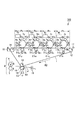
図1は、本発明に係る製造方法で製造された中間転写ベルトを用いることのできる電子写真方式の画像形成装置(電子写真画像形成装置)の一例の断面構成図である。
[First Embodiment]
1. Image Forming Apparatus FIG. 1 is a cross-sectional configuration diagram of an example of an electrophotographic image forming apparatus (electrophotographic image forming apparatus) that can use an intermediate transfer belt manufactured by a manufacturing method according to the present invention.
図1に示す画像形成装置100は、中間転写ベルト1の直線区間に、第1、第2、第3、第4の画像形成部Py、Pm、Pc、Pkの4つの画像形成部(ステーション)が配列されたタンデム型フルカラー複写機である。各画像形成部Py、Pm、Pc、Pkの感光ドラム2にそれぞれ形成されたイエロー、マゼンタ、シアン、ブラックの各色のトナー像が、各一次転写部T1y、T1m、T1c、T1kにおいて中間転写ベルト1に順次重ねられて一次転写される。中間転写ベルト1に一次転写された4色のトナー像は、二次転写部T2へ搬送されて、記録材Pへ二次転写される。二次転写部T2で4色のトナー像を二次転写された記録材Pは、定着装置3で加熱及び加圧されて、その表面にトナー像が定着された後に、画像形成装置100の外部へと排出される。定着装置3は、ハロゲンヒータを備えた定着ローラ4と、定着ローラ4に圧接する加圧ローラ5とを有するローラ定着器であり、記録材Pに静電的に担持されたトナー像を、熱と圧力により記録材Pの表面に固定する。
An
ここで、画像形成部Py、Pm、Pc、Pkは、それぞれが有する現像装置6y、6m、6c、6kで用いるトナーの色がそれぞれイエロー、マゼンタ、シアン、ブラックと異なる以外は実質的に同一の構成とされる。したがって、以下、代表して第1の画像形成部Pyについて説明する。
Here, the image forming units Py, Pm, Pc, and Pk are substantially the same except that the colors of the toners used in the developing
画像形成部Pyは、トナー像を担持する回転可能な像担持体として、ドラム型(円筒形)の電子写真感光体(感光体)である感光ドラム2yを有する。感光ドラム2yの周囲には、帯電手段としての帯電装置7y、露光手段としての露光装置8y、現像手段としての現像装置6y、一次転写手段としての一次転写ローラ9y、クリーニング手段としてのクリーニング装置10yが配置されている。
The image forming unit Py includes a photosensitive drum 2y that is a drum-type (cylindrical) electrophotographic photosensitive member (photosensitive member) as a rotatable image carrier that supports a toner image. Around the photosensitive drum 2y, there are a
感光ドラム2yは、アルミニウム製シリンダの外周面に、帯電極性が負極性の有機感光体材料(OPC)の光導電体層が形成されて構成されている。感光ドラム2yは、図示しない駆動手段としての駆動モータによって、200mm/秒の周速度(プロセススピード)で図中矢印R1方向に回転駆動される。 The photosensitive drum 2y is configured by forming a photoconductor layer of an organic photosensitive material (OPC) having a negative polarity on the outer peripheral surface of an aluminum cylinder. The photosensitive drum 2y is rotationally driven in a direction indicated by an arrow R1 in the drawing at a peripheral speed (process speed) of 200 mm / second by a driving motor (not shown) as driving means.
帯電装置7yは、感光ドラム2yに当接して配置された接触帯電部材としての帯電ローラで構成される。帯電ローラ7yは、図示しない付勢手段としての加圧バネによって、総荷重3N(≒300gf)で感光ドラム2yに圧接され、感光ドラム2yの回転に従動して回転する。帯電ローラ7yは、金属軸(芯金)上に、カーボン分散EPDM系発泡スポンジゴムの弾性層、カーボン分散NBR系ゴムの中間層、カーボンを分散させたフッ素系樹脂の離型層を順に積層した3層構成を有する。帯電ローラ7yの芯金には、図示しない帯電電源から、直流電圧−600Vと周波数1500Hzの交流電圧1400Vpp(ピーク間電圧)とが重畳された帯電電圧(帯電バイアス)が印加される。
The
露光装置8yは、イエローの分解色画像を展開した走査線画像データをON−OFF変調したレーザービームを、回転ミラーで走査して、帯電した感光ドラム2yの表面を露光する。これにより、感光ドラム2yの表面に静電潜像(静電像)が形成される。
The
現像装置6yは、現像剤として、主に非磁性トナー粒子(トナー)と、磁性キャリア粒子(キャリア)とが混合された二成分現像剤を用いる。現像装置6yは、二成分現像剤を攪拌して、トナーを負極性(正規の帯電極性)に帯電させる。現像装置6yは、現像剤担持体として内部に固定磁極が配置された現像スリーブ11yを有する。帯電したトナーがキャリアの表面に付着した二成分現像剤は、固定磁極の磁力によって現像スリーブ11yの表面に穂立ち状態で担持されて、感光ドラム2yを摺擦する。現像スリーブ11yは、350μmのギャップを隔てて感光ドラム2yに対向して配置される。現像スリーブ11yは、感光ドラム2yに対してカウンタ方向(対向部で互いの移動方向が逆方向となる方向)に回転駆動される。現像スリーブ11yには、図示しない現像電源から、直流電圧−450Vに2000Hzの交流電圧1800Vppを重畳した現像電圧(現像バイアス)が印加される。そして、現像スリーブ11yよりも相対的に正極性となった感光ドラム2yの静電潜像の画像部へ現像スリーブ11y上の二成分現像剤からトナーが移動して、感光ドラム2y上の静電潜像が反転現像される。すなわち、一様に帯電処理された後に露光されることで電位の絶対値が低下した感光ドラム2y上の露光部に、感光ドラム2yの帯電極性と同極性に帯電したトナーが付着する。
The developing
中間転写ベルト1を介して感光ドラム1と対向する位置に、一次転写ローラ9yが配置されている。一次転写ローラ9yは、感光ドラム2yとの間に、総荷重10N(≒1000gf)で中間転写ベルト1を挟み込んで、感光ドラム2yと中間転写ベルト1との間に一次転写部T1yを形成する。一次転写ローラ9yは、中間転写ベルト1の回転に従動して回転する。一次転写ローラ9yは、金属軸上に、弾性層として半導電性のポリウレタン系発泡ゴム層を形成して構成されている。この一次転写ローラ9yは、弾性層の硬度がアスカーC硬度10で、ローラ抵抗が1×10⁶Ωの半導電性ローラである。なお、ローラ抵抗は、温度23℃、相対湿度50%RHの環境で、一次転写ローラ9yの金属軸の両端に各500gの錘を載せ、電流計を介してアースされた金属板に押圧し、金属軸の一端に50Vの電圧を印加して測定した金属板に流れる電流から算出した。一次転写ローラ9yの金属軸には、一次転写電源E1yから、一次転写電圧(一次転写バイアス)として正極性の直流電圧が印加される。これにより、感光ドラム2yに担持された負極性に帯電したトナーからなるトナー像は、一次転写部T1yを通過する中間転写ベルト1に転写(一次転写)される。
A
クリーニング装置10yは、硬度がデュロメータA硬度70で厚みが2mmのポリウレタン製の板状部材で構成されたクリーニングブレードを有する。クリーニング装置10yは、クリーニングブレードによって回転する感光ドラム2yの表面を摺擦して、中間転写ベルト1に一次転写されずに感光ドラム2yの表面に残留した一次転写残トナーを感光ドラム2yの表面から除去して回収する。
The cleaning device 10y has a cleaning blade made of a polyurethane plate-like member having a durometer A hardness of 70 and a thickness of 2 mm. The cleaning device 10y rubs the surface of the photosensitive drum 2y rotated by the cleaning blade, and the primary transfer residual toner remaining on the surface of the photosensitive drum 2y without being primarily transferred to the
例えばフルカラー画像の形成時には、上述のような帯電、露光、現像、一次転写、クリーニングが、各画像形成部Py、Pm、Pc、Pkにおいて行われ、4色のトナー像が中間転写ベルト1上に順次重ね合わせるようにして一次転写される。
For example, when forming a full-color image, the above-described charging, exposure, development, primary transfer, and cleaning are performed in each image forming unit Py, Pm, Pc, and Pk, and four color toner images are formed on the
中間転写ベルト1は、複数の支持ローラとして、駆動ローラ12、バックアップローラ13及びテンションローラ14に掛け渡されて支持されている。中間転写ベルト1は、図示しない駆動手段としての駆動モータによって駆動ローラ12が回転駆動されることで、図中矢印R2方向に回転駆動される。中間転写ベルト1の電気抵抗としては、表面抵抗率が1×10¹⁰Ω/□以上、1×1014Ω/□以下であることが好ましい。また、表面抵抗率が1×1011Ω/□以上、1×1013Ω/□以下であることがより好ましい。表面抵抗率の測定は、温度23℃、相対湿度50%RHの環境で、三菱化学アナリテック社製のハイレスタ−UPとURプローブ(主電極外径16mm、リング電極内径30mm)、レジテーブルUFL(測定はテフロン(登録商標)面で実施)を使用して行った。また、印加電圧100V、チャージ時間10秒の条件で測定した。なお、中間転写ベルト1の製造方法については後述して詳しく説明する。
The
中間転写ベルト1を介してバックアップローラ13と対向する位置に、二次転写手段としての二次転写ローラ16が配置されている。二次転写ローラ19は、バックアップローラ13との間に中間転写ベルト1を挟みこんで、中間転写ベルト1と二次転写ローラ19との間に二次転写部T2を形成する。中間転写ベルト1に一次転写されたトナー像は、転写材Pが二次転写部T2において中間転写ベルト1と二次転写ローラ19とで挟持されて搬送される過程で、中間転写ベルト1から記録材Pへ転写(二次転写)される。記録材Pは、二次転写部T2を通過するトナー像とタイミングが合わされてレジストローラ15から二次転写部T2に搬送される。二次転写ローラ19は、その回転中心がバックアップローラ13の中心よりも、記録材Pの搬送方向の上流側に2mmずれた位置に配置される。そして、二次転写ローラ19は、中間転写ベルト1を介してバックアップローラ13の方向に、総荷重50N(≒5kgf)で押し付けられ、中間転写ベルト1の回転に従動して回転する。バックアップローラ13は、金属軸上に、弾性層としてカーボン分散EPDMゴムの低抵抗層を形成したゴムローラであり、接地電位に接続されている。また、二次転写ローラ19は、金属軸上に、弾性層として半導電性のNBRゴムとヒドリンゴムを主成分とする発泡ゴム層を形成して構成されている。この二次転写ローラ19は、硬度がアスカーC硬度30で、ローラ抵抗が1×108Ωの半導電性ローラである。なお、ローラ抵抗は、温度23℃、相対湿度50%RHの環境で、二次転写ローラ19の金属軸の両端に各500gの錘を載せ、電流計を介してアースされた金属板に押圧し、金属軸の一端に2kVの電圧を印加して測定した金属板に流れる電流から算出した。二次転写ローラ19の金属軸には、二次転写電源E2から、二次転写電圧(二次転写バイアス)として正極性の直流電圧が印加される。これにより、中間転写ベルト1に担持された負極性に帯電したトナーからなるトナー像は、二次転写部T2を通過する記録材Pに二次転写される。
A
記録材Pに二次転写されずに中間転写ベルト1の表面に残留した二次転写残トナーや、二次転写部T2で記録材Pから中間転写ベルト1に付着した紙粉などの付着物は、中間転写ベルトクリーニング装置18により除去されて回収される。中間転写ベルトクリーニング装置18は、硬度がデュロメータA硬度75で厚みが2mmのポリウレタン製の板状部材で構成されたクリーニングブレードを有する。そして、中間転写ベルトクリーニング装置18は、クリーニングブレードの先端を中間転写ベルト1の表面にカウンタ方向(自由端が中間転写ベルト1の移動方向の上流側を向く方向)に当接させて、回転する中間転写ベルト1の表面を摺擦する。これにより、中間転写ベルトクリーニング装置18は、中間転写ベルト1上の二次転写残トナーや紙粉などの付着物を中間転写ベルト1の表面から除去して回収する。
The secondary transfer residual toner remaining on the surface of the
2.中間転写ベルトの製造方法
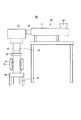
次に、本実施形態における中間転写ベルト1の製造方法について説明する。図2は、本実施形態で用いる製造装置20の概略構成を示す模式図である。また、図3は、本実施形態で用いる円筒ダイス33の側面及び下面の概略構成を示す模式図である。
2. Method for Manufacturing Intermediate Transfer Belt Next, a method for manufacturing the
製造装置20は、熱可塑性樹脂としてのポリエーテルエーテルケトン樹脂(PEEK樹脂)と導電性フィラーとしての導電性カーボンブラック(カーボン)とを含有する樹脂組成物から、中間転写ベルト1に用いられるシームレスベルトを製造する。
The
製造装置20は、PEEK樹脂にカーボンを分散させた樹脂組成物のペレット(以下「材料ペレット」ともいう。)を溶融して押し出しシームレスベルトを成形する一軸押出成形機30を有する。
The
ここで、材料ペレットは、公知の技術でPEEK樹脂にカーボンを二軸混練機により均一に分散させたものである。より詳しくは、次のようにして作製したものである。つまり、PEEK樹脂とカーボンをタンブラーで混合して2軸混錬機に供給する。そして、バレル温度をPEEK樹脂の溶融温度以上、熱劣化を起こさない温度以下、例えば340℃以上、420℃以下で混錬しつつ、溶融押出を行い、裁断してペレットを作製する。 Here, the material pellet is obtained by uniformly dispersing carbon in PEEK resin with a twin-screw kneader by a known technique. More specifically, it was produced as follows. That is, PEEK resin and carbon are mixed with a tumbler and supplied to a twin-screw kneader. Then, melt extrusion is performed while kneading at a barrel temperature not lower than the melting temperature of the PEEK resin and not higher than a temperature at which thermal deterioration does not occur, for example, not lower than 340 ° C. and not higher than 420 ° C.
PEEK樹脂としては、下記式(1)で表されるオキシ−1,4−フェニレン−オキシ−フェニレン−カルボニル−1,4−フェニレンの構成単位を有する重合体を使用することができる。また、導電性カーボンブラックとしては、アセチレンブラック、オイルファーネスブラック、サーマルブラック、チャネルブラックなどが挙げられる。中でも、アセチレンブラックが好ましい。本実施形態では、PEEK樹脂として、Victrex社製、商品名ビクトレックスPEEK450Gを使用した。また、本実施形態では、カーボンとして、電気化学工業製、商品名デンカブラックを使用した。PEEK樹脂中のカーボン含有量は、16wt%以上、26wt%以下の範囲で、所望の表面抵抗率の中間転写ベルト1となるように調整した。
As the PEEK resin, a polymer having a structural unit of oxy-1,4-phenylene-oxy-phenylene-carbonyl-1,4-phenylene represented by the following formula (1) can be used. Examples of the conductive carbon black include acetylene black, oil furnace black, thermal black, and channel black. Of these, acetylene black is preferable. In the present embodiment, a trade name Victrex PEEK450G manufactured by Victrex was used as the PEEK resin. In this embodiment, Denka Black manufactured by Denki Kagaku Kogyo was used as the carbon. The carbon content in the PEEK resin was adjusted in the range of 16 wt% to 26 wt% so that the

一軸押出成形器30は、ホッパー34を有する。一軸押出成形機30には、ホッパー34から図示しない重量フィーダーで計量された材料ペレットが導入される。本実施形態では、押出量は毎時4kgに設定され、材料ペレットが5秒毎に投入量をフィードバック制御しながら略連続的に毎時4kgで一軸押出成形機30に導入される、所謂ハングリーフィード方式を採用した。
The
また、一軸押出成形機30は、バレル31を有する。バレル31は、外周面に加熱のためのヒーターが配置され、内部に1本のスクリューが配置されている。ホッパー34から導入された材料ペレットは、バレル31で溶融温度以上に加熱され、溶融状態で搬送される。バレル31のヒーターの設定温度は、一軸押出成形機30の(バレル31内の溶融樹脂の搬送方向に対して)上流から下流方向に温度が高くなる勾配が付けられており、360℃以上、380℃以下に制御される。
The
また、一軸押出成形機30は、ギアポンプ32を有する。ギアポンプ32は、外周面に加熱のためのヒーターが配置され、毎時4kgの溶融樹脂を搬送する。ギアポンプ32のヒーターの設定温度は、380℃に制御される。
Further, the
また、一軸押出成形機30は、円筒ダイス33を有する。図3に示すように、円筒ダイス33は、同心円状の外リップ33aと内リップ33bとを有し、外リップ33aの外周面に外リップヒーター33cが配置され、内リップ33bの内部に内リップヒーター33dが配置されている。ギアポンプ32から送られた一定量の溶融樹脂は、外リップ41と内リップ42とで形成された、外リップ33a及び内リップ42と同心円状の隙間であるリップ33eから、図2に示すように本実施形態では鉛直方向下方にチューブ1Aの形状で押し出される。外リップヒーター33c、内リップヒーター33dの設定温度は、380℃に制御される。本実施形態では、円筒ダイス33の内リップ33bの外径は255mm、外リップ33aの内径は256.4mmである。したがって、リップ33eの幅(リップ幅、リップクリアランス)は0.7mm(700μm)である。
Further, the
また、製造装置20は、冷却装置として第一マンドレル41、第二マンドレルを備えたチューブ冷却装置42、第三マンドレル43を有する。第一マンドレル41は、チューブ1Aの内側に配置され、一軸押出成形機30のダイス33から押し出されてチューブ1Aの形状に成形された樹脂を、溶融温度以下に冷却して固化させる。第一マンドレル41の外径は253mmで、結晶化度を制御するために内部に配置されたヒーターで230℃に制御される。チューブ冷却装置42は、内部に図示しない第二マンドレルが配置されており、チューブ1Aの搬送方向に対して上流の樹脂温度に影響がないように下方にエアーを噴出して、チューブ1Aを120℃以下になるように冷却する。第三マンドレル43は、チューブ1Aの内側に配置され、後述する引取装置50との間でチューブ1Aを挟持すると共に、チューブ1Aを更に冷却する。
Further, the
また、製造装置20は、チューブ1Aを引き取る引取装置(引取ユニット部)50を有する。引取装置50は、チューブAの外側に配置され、チューブ1Aを下方に引っ張る方向に回転する無端状のベルトを有して構成されており、そのベルトをチューブ1Aを挟んで第三マンドレル43に当接させることで、チューブ1Aを下方に引き取る。引取装置50は、チューブ1Aの外周に6台配置されている(図2には2台のみ図示)。ここで、円筒ダイス33からの樹脂の押出量は一定としているため、引取装置50の引取速度設定を調整することで、チューブ1Aの厚みを制御することが可能である。
Further, the
さらに、製造装置20は、切断装置60を有している。切断装置60は、連続して押し出されるチューブ1Aを所定の幅(チューブ1Aの搬送方向の長さ)で切断する。本実施形態では、チューブ1Aを幅450mmごとに切断してシームレスベルト(ベルト体)1Bとし、さらに公知の技術でシームレスベルト1Bの幅方向の両端部に補強テープを貼り、中間転写ベルト1を作製した。
Further, the
3.実施例及び比較例
上述の製造装置20を用いて、引取装置50の引取速度を調整することで、表1に示す実施例1〜3、比較例1の中間転写ベルト1を作製した。実施例1〜3、比較例1の中間転写ベルト1は、表1に示すように、周方向に6点測定した時の平均の厚みが60μm以上、87μm以下の範囲、周方向に6点測定した時の平均の表面抵抗率が2×10¹¹Ω/□以上、8×1012Ω/□以下の範囲で異なる。この表面抵抗率は、中間転写ベルト1の初期(画像形成に使用する前)の値である。繰り返し使用後の表面抵抗率については後述する。なお、リップ幅も、周方向に6点測定した時の平均値で代表することができる。
3. Examples and Comparative Examples Using the
表1に示す引取量は、「リップ幅W(μm)÷成形されたシームレスベルトの厚みの平均値T(μm)」の計算式で定義されるものである。この引取量は、円筒ダイス33から一定量で押し出された樹脂を所望の厚みにするために引き伸ばす量を表している。具体的には、リップ幅が700μmの場合、例えば厚み60μmのシームレスベルト1Bでは、引取量は「700÷60」で「11.7」と計算される。同様に、例えば厚み85μmのシームレスベルト1Bでは、引取量は「8.2」と計算される。すなわち、引取量が小さい方が、円筒ダイス33から樹脂が押し出された時に引き伸ばされる量が小さい(押出量が一定量の場合、シームレスベルトの厚みは厚い)ことを表している。
The take-up amount shown in Table 1 is defined by a calculation formula of “lip width W (μm) ÷ average thickness T of molded seamless belt T (μm)”. This take-off amount represents the amount that the resin extruded from the
また、上述と同様の製造方法において、内リップ33bの外径が255mm、外リップ33aの内径が257mm、リップ幅が1.0mm(1000μm)の円筒ダイス33を使用して、表1に示す比較例2の中間転写ベルト1も作製した。この中間転写ベルト1は、上記同様にして測定した平均の厚みが82μm、上記同様にして測定した平均の表面抵抗率が2×10¹²Ω/□である。この表面抵抗率は、中間転写ベルト1の初期(画像形成に使用する前)の値である。繰り返し使用後の表面抵抗率については後述する。また、この中間転写ベルト1の引取量は12.2である。
Further, in the same manufacturing method as described above, a comparison is made as shown in Table 1 using a
ここで、表面抵抗率の調整方法について説明する。本実施形態の中間転写ベルト1では、表面抵抗率は、PEEK樹脂中のカーボン含有量で調整するが、表2に示すように、同一のカーボン含有量でも、引取量を変えた場合には表面抵抗率が著しく変化する。
Here, a method for adjusting the surface resistivity will be described. In the
そのため、カーボン含有量を変量させた材料ペレット(PEEK樹脂にカーボンを分散させた樹脂組成物)を数水準用意して、その混合比率を変えることで表面抵抗率を調整した。具体的には、引取量を大きく(シームレスベルトの厚みは薄い)すると表面抵抗率は高くなるため、引取量が大きいシームレスベルトは、引取量が小さいシームレスベルトよりPEEK樹脂中に含有されるカーボンの量が多くなるようにして表面抵抗率を調整した。それぞれのカーボン含有量の材料ペレットは、一軸押出成形機30内で溶融され、スクリューで混合されるため、カーボン含有量が異なる材料ペレットを使用したことで電気抵抗ムラが大きくなることはなく、表面抵抗率を調整することが可能であった。
Therefore, several levels of material pellets (resin composition in which carbon was dispersed in PEEK resin) with varying carbon content were prepared, and the surface resistivity was adjusted by changing the mixing ratio. Specifically, since the surface resistivity increases when the take-up amount is increased (the thickness of the seamless belt is thin), the seamless belt having a large take-up amount is more susceptible to carbon contained in the PEEK resin than the seamless belt having a small take-up amount. The surface resistivity was adjusted so as to increase the amount. Since the material pellets of each carbon content are melted in the
次に、中間転写ベルト1の通電劣化による電気抵抗の低下の評価方法について説明する。評価は、上述のカラー複写機に実施例及び比較例の中間転写ベルト1を搭載し、25万枚プリント出力(A4横通紙)することで実施した。なお、この評価は、電気抵抗の低下の原因を究明するために、電気抵抗の低下がより顕著となる低湿環境、具体的には温度23℃、相対湿度5%に調整された評価室にカラー複写機を装置本体ごと入れて実施した。
Next, a method for evaluating a decrease in electric resistance due to energization deterioration of the
次に、25万枚プリント出力後の画像と表面抵抗率の評価結果について説明する。評価結果は、表1及び図4に示す。 Next, an image after printing 250,000 sheets and the evaluation result of the surface resistivity will be described. The evaluation results are shown in Table 1 and FIG.
まず、25万枚プリント出力後の画像の評価結果については、引取量を比較例1、2よりも小さく設定した実施例1〜3の中間転写ベルト1を使用した場合、転写白抜けは発生しなかった。一方、引取量を実施例1〜3よりも大きく設定した比較例1、2の中間転写ベルト1を使用した場合、記録材Pの搬送方向の先端部で転写白抜けが発生した。
First, regarding the evaluation result of the image after printing 250,000 sheets, when the
次に、25万枚プリント出力後の表面抵抗率は、実施例1〜3の中間転写ベルト1では1×10¹⁰Ω/□以上であった。一方、記録材Pの先端部で転写白抜けが発生した比較例1、2の中間転写ベルト1では、8乗台(108Ω/□)まで低下していた。
Next, the surface resistivity after printing 250,000 sheets was 1 × 10 10 Ω / □ or more in the
そこで、更に評価結果を詳細に検討し、中間転写ベルト1の通電による電気抵抗の低下現象について、次のことが見出された。
(1)引取量を9.5以下に設定することで、繰り返し使用後の中間転写ベルト1の表面抵抗率を、転写白抜けの発生しない1×10¹⁰Ω/□以上に維持することが可能である。すなわち、例えば寿命の設定がA4横通紙で25万枚以上の本実施形態のカラー複写機などで用いられる中間転写ベルト1は、その寿命期間を通して表面抵抗率を1×1010Ω/□以上に維持するには、引取量を9.5以下に設定する必要がある(図4参照)。
(2)引取量が同水準で、カーボン含有量を調整することで表面抵抗率を概ね1×10¹¹Ω/□以上、1×1013以下の範囲とした中間転写ベルト1は、繰り返し使用後にはほぼ同じ水準まで表面抵抗率が低下する(実施例1、2の比較)。
(3)厚みが同水準で、リップ幅を変えることで引取量に差をつけた中間転写ベルト1では、引取量が大きい方が繰り返し使用後の表面抵抗率は小さくなる(実施例1、2と比較例2の比較)。
Accordingly, the evaluation results were further examined in detail, and the following was found with respect to the phenomenon of reduction in electrical resistance caused by energization of the
(1) By setting the take-up amount to 9.5 or less, it is possible to maintain the surface resistivity of the
(2) The
(3) In the
そこで、本実施形態では、ポリエーテルエーテルケトン樹脂と導電性カーボンブラックとを含有する樹脂組成物を溶融して円筒ダイスより押し出しながら延伸してシームレスベルトを成形するシームレスベルトの製造方法を、次のような設定とする。すなわち、円筒ダイスのリップ幅をW、前記シームレスベルトの厚みの平均値をTとしたとき、W/Tで定義される引取量を9.5以下に設定する。換言すれば、本実施形態では、上記樹脂組成物の溶融押出を行いながら延伸して、表面抵抗率の平均値が1×1010Ω/□以上、1×1014Ω/□以下、より好ましくは1×1011Ω/□以上、1×1013Ω/□以下のシームレスベルトを成形する。そして、この場合に、本実施形態では、引取量W/Tを、シームレスベルトの寿命期間を通してシームレスベルトの表面抵抗率の平均値が1×1010Ω/□以上に維持されるように設定する。 Therefore, in this embodiment, a seamless belt manufacturing method in which a resin composition containing a polyether ether ketone resin and conductive carbon black is melted and stretched while being extruded from a cylindrical die to form a seamless belt, Set as follows. That is, when the lip width of the cylindrical die is W and the average value of the thickness of the seamless belt is T, the take-up amount defined by W / T is set to 9.5 or less. In other words, in the present embodiment, the resin composition is stretched while being melt-extruded, and the average value of the surface resistivity is 1 × 10 10 Ω / □ or more and 1 × 10 14 Ω / □ or less, more preferably. Forms a seamless belt of 1 × 10 11 Ω / □ or more and 1 × 10 13 Ω / □ or less. In this case, in this embodiment, the take-up amount W / T is set so that the average value of the surface resistivity of the seamless belt is maintained at 1 × 10 10 Ω / □ or more throughout the lifetime of the seamless belt. .
なお、シームレスベルトの厚みは、これに限定されるものではないが、50μm以上、100μm以下であることが、シームレスベルトの厚みを均一にしやすく、また柔軟性を良好にする点から好ましい。また、リップ幅は、これに限定されるものではないが、上述のような厚みのシームレスベルトを成形する場合、1000μm以下であることが、良好な特性のシームレスベルトを成形する点から好ましい。そして、所定のリップ幅に対して、引取速度を調整することで、引取量を上記所定値以下して、所望の厚みのシームレスベルトを成形することができる。また、引取量は、1より大きく、これに限定されるものではないが、典型的には8以上である。 The thickness of the seamless belt is not limited to this, but is preferably 50 μm or more and 100 μm or less from the viewpoint of making the thickness of the seamless belt uniform and improving flexibility. Further, the lip width is not limited to this, but when a seamless belt having the above thickness is formed, it is preferably 1000 μm or less from the viewpoint of forming a seamless belt having good characteristics. Then, by adjusting the take-up speed with respect to a predetermined lip width, the take-up amount can be made equal to or less than the predetermined value to form a seamless belt having a desired thickness. Further, the take-up amount is larger than 1 and is not limited to this, but is typically 8 or more.
ここで、図5を参照して、上述の電気抵抗の低下現象のメカニズムについて説明する。 Here, with reference to FIG. 5, the mechanism of the above-described phenomenon of a decrease in electrical resistance will be described.
図5(A)は、引取量が相対的に小さい場合のカーボン粒子(二次ストラクチャー)のPEEK樹脂中での分散状態を表した模式図である。一般に、カーボンを分散させて半導電性を付与した半導電性樹脂では、カーボン粒子間aをトンネル電流が流れることで、図5(A)中矢印で示す導電経路dに微小な電流が流れて半導電性を示すと言われている。 FIG. 5A is a schematic diagram showing a dispersion state of carbon particles (secondary structure) in the PEEK resin when the take-up amount is relatively small. In general, in a semiconductive resin in which carbon is dispersed to impart semiconductivity, a small current flows through a conductive path d indicated by an arrow in FIG. 5A because a tunnel current flows between carbon particles a. It is said to exhibit semiconductivity.
図5(B)は、図5(A)の矢印eの方向へ樹脂を延伸して引取量を図5(A)よりも大きくした場合の、カーボン粒子のPEEK樹脂中での分散状態を表した模式図である。図5(B)では、図5(A)において存在したカーボン粒子間a以外に、樹脂をより延伸したことでカーボン粒子の絡み付きが解れて、カーボン粒子間aよりカーボン粒子間距離が小さいカーボン粒子間bが生成する。そのため、引取量を大きくすると、表面抵抗率が高くなる(表2参照)。 FIG. 5B shows the dispersion state of the carbon particles in the PEEK resin when the resin is stretched in the direction of arrow e in FIG. 5A to make the take-up amount larger than that in FIG. 5A. FIG. In FIG. 5 (B), in addition to the inter-carbon particle a existing in FIG. 5 (A), the entanglement of the carbon particles is released by further stretching the resin, and the carbon particle distance is smaller than the inter-carbon particle a. The interval b is generated. Therefore, when the take-up amount is increased, the surface resistivity is increased (see Table 2).
そして、図5(B)の樹脂組成物に転写電圧が印加されると、カーボン粒子間bはカーボン粒子間の距離が極めて小さいため、カーボン粒子とカーボン粒子の間で放電が発生する。その時に一時的に流れる放電による電流は、トンネル電流と比較して著しく多く流れる。そのため、その大電流により、カーボン粒子間b及びカーボン粒子間aの樹脂が炭化して導電性を示し、図5(C)中に太い矢印で示す導電経路d’が形成されて、表面抵抗率が低下する。すなわち、引取量が大きいほどカーボン粒子間bの発生量が多いため、それに起因する通電での電気抵抗の低下はより顕著となる。 When a transfer voltage is applied to the resin composition shown in FIG. 5B, since the distance between the carbon particles b is extremely small, a discharge occurs between the carbon particles. The current due to the discharge that temporarily flows at that time flows significantly more than the tunnel current. Therefore, due to the large current, the resin between the carbon particles b and the carbon particle a is carbonized to show conductivity, and a conductive path d ′ indicated by a thick arrow is formed in FIG. Decreases. That is, since the generation amount of the carbon particle b increases as the take-up amount increases, the decrease in electrical resistance due to energization due to it becomes more remarkable.
以上、本実施形態では、PEEK樹脂と導電性カーボンブラックとを含有する樹脂組成物を溶融して押し出すと共に延伸することで中間転写ベルト1を製造する際に、引取量を所定値よりも小さくする。これにより、中間転写ベルト1の通電による電気抵抗の低下を抑制し、中間転写ベルト1の耐久性を向上させることが可能となる。したがって、本実施形態によれば、例えば従来のポリイミドの中間転写ベルトと同等の機能を有した中間転写ベルトを、低コストで提供することが可能となり、それを用いた画像形成装置のランニングコストを低減することが可能となる。
As described above, in the present embodiment, when the
[その他の実施形態]
以上、本発明を具体的な実施形態に即して説明したが、本発明は上述の実施形態に限定されるものではない。
[Other Embodiments]
As mentioned above, although this invention was demonstrated according to specific embodiment, this invention is not limited to the above-mentioned embodiment.
例えば、上述の実施形態では、シームレスベルトが中間転写方式の画像形成装置において中間転写ベルトとして用いられる場合を例に説明したが、本発明はこれに限定されるものではない。本発明は、使用(特に、電圧の印加)により電気抵抗が低下してしまうことが望ましくない、画像形成装置用のシームレスベルトの製造方法として、広く適用できるものである。例えば、シームレスベルトは、直接転写方式の画像形成装置において記録材担持ベルトとして用いられるものであってもよい。直接転写方式の画像形成装置は、図1に示す中間転写方式の画像形成装置における中間転写ベルトに代えて、記録材担持ベルトを有する。そして、各画像形成部で像担持体に形成されたトナー像は、図1の画像形成装置における一次転写手段に対応する転写手段に電圧が印加されるなどして、記録材担持ベルト上に担持されて搬送される記録材上に転写される。 For example, in the above-described embodiment, the case where the seamless belt is used as the intermediate transfer belt in the intermediate transfer type image forming apparatus has been described as an example. However, the present invention is not limited to this. The present invention can be widely applied as a method for producing a seamless belt for an image forming apparatus, in which it is not desirable that the electrical resistance is lowered by use (particularly, application of voltage). For example, the seamless belt may be used as a recording material carrying belt in a direct transfer type image forming apparatus. The direct transfer type image forming apparatus has a recording material carrying belt instead of the intermediate transfer belt in the intermediate transfer type image forming apparatus shown in FIG. The toner image formed on the image carrier in each image forming unit is carried on the recording material carrying belt by applying a voltage to the transfer means corresponding to the primary transfer means in the image forming apparatus of FIG. And transferred onto the recording material to be conveyed.
1 中間転写ベルト
20 製造装置
30 一軸押出成形機
33 円筒ダイス
50 引取装置
DESCRIPTION OF
Claims (4)
前記円筒ダイスのリップ幅をW、前記シームレスベルトの厚みの平均値をTとしたとき、W/Tで定義される引取量を9.5以下に設定することを特徴とするシームレスベルトの製造方法。 In a method for producing a seamless belt, a resin composition containing a polyether ether ketone resin and conductive carbon black is melted and stretched while being extruded from a cylindrical die to form a seamless belt.
A method for producing a seamless belt, wherein the take-up amount defined by W / T is set to 9.5 or less, where W is the lip width of the cylindrical die and T is the average thickness of the seamless belt. .
前記円筒ダイスのリップ幅をW、前記シームレスベルトの厚みの平均値をTとしたとき、W/Tで定義される引取量を、前記シームレスベルトの寿命期間を通して前記シームレスベルトの表面抵抗率の平均値が1×1010Ω/□以上に維持されるように設定することを特徴とするシームレスベルトの製造方法。 A resin composition containing a polyether ether ketone resin and conductive carbon black is melted and stretched while being extruded from a cylindrical die, and the average value of surface resistivity is 1 × 10 10 Ω / □ or more, 1 × 10 14 In a seamless belt manufacturing method for forming a seamless belt of Ω / □ or less,
When the lip width of the cylindrical die is W and the average thickness of the seamless belt is T, the take-up amount defined by W / T is the average of the surface resistivity of the seamless belt throughout the lifetime of the seamless belt. A method for producing a seamless belt, wherein the value is set so as to be maintained at 1 × 10 10 Ω / □ or more.
Priority Applications (1)
| Application Number | Priority Date | Filing Date | Title |
|---|---|---|---|
| JP2014245420A JP2016109792A (en) | 2014-12-03 | 2014-12-03 | Manufacturing method of seamless belt |
Applications Claiming Priority (1)
| Application Number | Priority Date | Filing Date | Title |
|---|---|---|---|
| JP2014245420A JP2016109792A (en) | 2014-12-03 | 2014-12-03 | Manufacturing method of seamless belt |
Publications (1)
| Publication Number | Publication Date |
|---|---|
| JP2016109792A true JP2016109792A (en) | 2016-06-20 |
Family
ID=56123970
Family Applications (1)
| Application Number | Title | Priority Date | Filing Date |
|---|---|---|---|
| JP2014245420A Pending JP2016109792A (en) | 2014-12-03 | 2014-12-03 | Manufacturing method of seamless belt |
Country Status (1)
| Country | Link |
|---|---|
| JP (1) | JP2016109792A (en) |
Cited By (2)
| Publication number | Priority date | Publication date | Assignee | Title |
|---|---|---|---|---|
| CN108982531A (en) * | 2017-06-02 | 2018-12-11 | 柯尼卡美能达株式会社 | The check device of tubular article |
| CN109031908A (en) * | 2017-06-09 | 2018-12-18 | 柯尼卡美能达株式会社 | The manufacturing device of the tubular articles such as the intermediate transfer belt before being cut off |
-
2014
- 2014-12-03 JP JP2014245420A patent/JP2016109792A/en active Pending
Cited By (3)
| Publication number | Priority date | Publication date | Assignee | Title |
|---|---|---|---|---|
| CN108982531A (en) * | 2017-06-02 | 2018-12-11 | 柯尼卡美能达株式会社 | The check device of tubular article |
| CN108982531B (en) * | 2017-06-02 | 2021-06-15 | 柯尼卡美能达株式会社 | Inspection device for cylindrical object |
| CN109031908A (en) * | 2017-06-09 | 2018-12-18 | 柯尼卡美能达株式会社 | The manufacturing device of the tubular articles such as the intermediate transfer belt before being cut off |
Similar Documents
| Publication | Publication Date | Title |
|---|---|---|
| JP5533022B2 (en) | Semiconductive composite resin | |
| JP6724554B2 (en) | Intermediate transfer member and image forming apparatus | |
| JP2004310064A (en) | Roll member and image forming apparatus | |
| JP2016109792A (en) | Manufacturing method of seamless belt | |
| JP5640406B2 (en) | Semiconductive composite resin | |
| JP2000181251A (en) | Image forming device and transfer roll | |
| JP2022049675A (en) | Intermediate transfer body and image forming apparatus | |
| JP6221741B2 (en) | Intermediate transfer body, tubular body unit, image forming apparatus, and process cartridge | |
| JP6156735B2 (en) | Belt member, image forming apparatus, and belt member manufacturing method | |
| JP4096526B2 (en) | Intermediate transfer member, method of manufacturing intermediate transfer member, and image forming apparatus | |
| JP6331868B2 (en) | Extruded tubular body, tubular body unit, intermediate transfer body, recording medium transport body, and image forming apparatus | |
| CN111722496A (en) | Charging member, charging device, process cartridge, and image forming apparatus | |
| JP2007010714A (en) | Belt for electrophotography and image forming apparatus | |
| JP6127916B2 (en) | Tubular body, tubular molded body unit, intermediate transfer body, image forming apparatus, and process cartridge | |
| JP7175742B2 (en) | Intermediate transfer belt and image forming apparatus | |
| JP2019032463A (en) | Intermediate transfer belt and image forming apparatus | |
| JP6922191B2 (en) | Conductive member for image forming device, transfer unit for image forming device and image forming device | |
| JP2017126017A (en) | Resin belt and method for manufacturing the same, and image forming apparatus | |
| JP4206722B2 (en) | Semiconductive belt and image forming apparatus using the same | |
| JP2016218427A (en) | Structure composed of semiconductor resin composition, intermediate transfer body, and image forming apparatus | |
| JP3943976B2 (en) | Belt-shaped transfer member, method for manufacturing belt-shaped transfer member, image forming apparatus, and intermediate transfer belt-latent image carrier integrated cartridge | |
| JP2007121553A (en) | Transfer roll and image forming apparatus | |
| JP6883197B2 (en) | Charging member, charging device, process cartridge, and image forming device | |
| JP6500361B2 (en) | Semiconductive resin material, semiconductive intermediate transfer belt and image forming apparatus | |
| JP6642171B2 (en) | Image forming apparatus cylindrical member, image forming apparatus cylindrical member unit, and image forming apparatus |