JP2016109397A - Temperature detection device - Google Patents
Temperature detection device Download PDFInfo
- Publication number
- JP2016109397A JP2016109397A JP2014249917A JP2014249917A JP2016109397A JP 2016109397 A JP2016109397 A JP 2016109397A JP 2014249917 A JP2014249917 A JP 2014249917A JP 2014249917 A JP2014249917 A JP 2014249917A JP 2016109397 A JP2016109397 A JP 2016109397A
- Authority
- JP
- Japan
- Prior art keywords
- boiled
- cover
- holder
- juice
- temperature detection
- Prior art date
- Legal status (The legal status is an assumption and is not a legal conclusion. Google has not performed a legal analysis and makes no representation as to the accuracy of the status listed.)
- Pending
Links
Images


Landscapes
- Physics & Mathematics (AREA)
- Engineering & Computer Science (AREA)
- General Physics & Mathematics (AREA)
- Measuring Temperature Or Quantity Of Heat (AREA)
- Chemical & Material Sciences (AREA)
- Combustion & Propulsion (AREA)
- Mechanical Engineering (AREA)
- General Engineering & Computer Science (AREA)
- Nonlinear Science (AREA)
- Gas Burners (AREA)
Abstract
Description
本発明は、ガスコンロの五徳上に載置された調理容器の底部に当接されて、調理容器の温度を検出する温度検出装置に関する。 The present invention relates to a temperature detection device that comes into contact with the bottom of a cooking vessel placed on the virtues of a gas stove and detects the temperature of the cooking vessel.
コンロバーナーの中央の開口部から突設されて、コンロバーナーで加熱調理される調理容器の温度を検出する温度検出装置が広く知られている。この温度検出装置は、温度センサーを内蔵するホルダーと、ホルダーが上下方向に移動可能な態様で取り付けられた支持パイプと、ホルダーと支持パイプとの間に設けられてホルダーを上方に付勢するコイルスプリングとを備えている。ホルダーは、五徳上に調理容器が載置されていない状態では、調理容器が載置される面よりも、ホルダーの上端面が突出した状態となっている。このため、五徳上に調理容器が載置されると、調理容器の底部でホルダーが押し下げられて、ホルダーの上端面が調理容器の底部に当接された状態となる。その結果、ホルダーに内蔵された温度センサーで調理容器の温度を検出することが可能となる。 2. Description of the Related Art A temperature detection device that projects from a central opening of a stove burner and detects the temperature of a cooking container that is cooked by the stove burner is widely known. This temperature detection device includes a holder with a built-in temperature sensor, a support pipe attached in such a manner that the holder can move in the vertical direction, and a coil provided between the holder and the support pipe to bias the holder upward. And a spring. In the state where the cooking container is not placed on the virtues, the holder has a state in which the upper end surface of the holder protrudes from the surface on which the cooking container is placed. For this reason, when the cooking container is placed on Gotoku, the holder is pushed down at the bottom of the cooking container, and the upper end surface of the holder comes into contact with the bottom of the cooking container. As a result, the temperature of the cooking container can be detected by the temperature sensor built in the holder.
また、加熱調理中には調理容器から煮零れが発生することがある。ホルダーの下端の支持パイプとの隙間に煮零れ汁が入り込むと、ホルダーが支持パイプに固着してしまい、ホルダーが上下方向に移動することができなくなる。すると、五徳上に調理容器を置いてもホルダーの上端面を調理容器の底部に当接させることができなくなって、調理容器の温度を検出できなくなる。そこで、下向きに広がる円錐筒状部材(煮零れ汁カバー)をホルダーに取り付けて、ホルダーの下端の部分を覆うようにすることで、たとえ煮零れが生じても、ホルダーと支持パイプとの隙間には煮零れ汁が入り込まないようにした温度検出装置が提案されている(特許文献1)。 In addition, simmering may occur from the cooking container during cooking. If boiled juice enters the gap between the lower end of the holder and the support pipe, the holder is fixed to the support pipe, and the holder cannot move in the vertical direction. Then, even if a cooking container is placed on Gotoku, the upper end surface of the holder cannot be brought into contact with the bottom of the cooking container, and the temperature of the cooking container cannot be detected. Therefore, by attaching a conical cylindrical member that spreads downward (boiled juice cover) to the holder so as to cover the lower end portion of the holder, even if simmering occurs, the gap between the holder and the support pipe A temperature detection device has been proposed in which no boiled soup enters (Patent Document 1).
ここで、ホルダーの下端(および、その近傍の支持パイプ)に煮零れ汁がかからないようにするためには、煮零れ汁カバーの大きさ(外径)は大きい方が望ましいが、コンロバーナーの開口部は、燃焼に必要な二次空気の供給通路となっている。このため、円錐筒状の煮零れ汁カバーの大きさは、二次空気の供給が妨げられてコンロバーナーの燃焼状態が悪化することがなく、尚且つ、ホルダーの下端に煮零れ汁がかからない大きさに設定されている。 Here, in order to prevent boiled juice from being applied to the lower end of the holder (and the supporting pipe in the vicinity thereof), it is desirable that the size (outer diameter) of the boiled juice cover is larger, but the opening of the stove burner The part serves as a supply passage for secondary air necessary for combustion. For this reason, the size of the conical simmered juice cover is such that the supply of secondary air is not hindered and the combustion state of the stove burner is not deteriorated, and the simmered juice is not applied to the lower end of the holder. Is set.
しかし、上記の提案されている温度検出装置では、コンロバーナーを長期に亘って使用していると、固化した煮零れ汁によって煮零れ汁カバーの外径が大きくなっていき、二次空気の供給が阻害されてコンロバーナーの燃焼状態を悪化させてしまうことがあるという問題があった。これは次のような理由による。先ず、煮零れ汁は粘度が高いので、煮零れ汁カバーの下端に溜まった時に外側に少し張り出した状態(溜まり状態)となる。そして、その溜まり状態で煮零れ汁が固化する結果、煮零れ汁カバーの外径が少し大きくなる。煮零れが生じる度にこのようなことが繰り返されるので、長期に亘る使用の間には、二次空気の供給を阻害する程度まで煮零れ汁カバーの外径が大きくなってしまい、コンロバーナーの燃焼状態を悪化させてしまう。 However, in the proposed temperature detection device, when the stove burner is used for a long time, the outer diameter of the boiled juice cover increases due to the solidified boiled juice, and the supply of secondary air There is a problem that the combustion state of the stove burner may be deteriorated by being inhibited. This is due to the following reason. First, since boiled soup has a high viscosity, when it is collected at the lower end of the boiled soup cover, it is in a state of being slightly overhanged (reserved state). Then, as a result of solidification of the boiled soup in the pooled state, the outer diameter of the boiled soup cover is slightly increased. Since this is repeated every time simmering occurs, the outer diameter of the simmering juice cover increases to the extent that the secondary air supply is hindered during long-term use. The combustion state will be worsened.
この発明は、従来の技術が有する上述した課題に対応してなされたものであり、長い間の使用によっても、コンロバーナーの燃焼状態を悪化させる虞のない温度検出装置の提供を目的とする。 The present invention has been made in response to the above-mentioned problems of the prior art, and an object of the present invention is to provide a temperature detection device that does not deteriorate the combustion state of the stove burner even when used for a long time.
上述した課題を解決するために、本発明の温度検出装置は次の構成を採用した。すなわち、
二次空気が供給される空気供給通路が中央を貫通して形成されたコンロバーナーに設けられて、五徳上に置かれた調理容器の温度を検出する温度検出装置において、
前記空気供給通路内に立設された支持パイプと、
略筒形状に形成されて、上下方向に移動可能な態様で下端側が前記支持パイプに嵌め込まれたホルダーと、
前記ホルダーの上端に取り付けられた集熱部と、
該集熱部の内部に取り付けられた温度センサーと、
前記ホルダーを上方に付勢するコイルバネと、
前記ホルダーの外周に取り付けられて前記調理容器からの煮零れ汁が外側表面を流下することにより、該煮零れ汁が該ホルダーの下端にかかることを防止する煮零れ汁カバーと
を備え、
前記煮零れ汁カバーの前記外側表面は、前記煮零れ汁が流下する経路の少なくとも一部が溝形状に形成されている
ことを特徴とする。
In order to solve the above-described problems, the temperature detection device of the present invention employs the following configuration. That is,
In the temperature detection device for detecting the temperature of the cooking container placed on the virtues, the air supply passage through which the secondary air is supplied is provided in the stove burner formed through the center,
A support pipe erected in the air supply passage;
A holder that is formed in a substantially cylindrical shape and is fitted in the support pipe at the lower end side in a manner movable in the vertical direction;
A heat collecting part attached to the upper end of the holder;
A temperature sensor attached to the inside of the heat collecting unit;
A coil spring for urging the holder upward;
A boiled juice cover that is attached to the outer periphery of the holder and prevents the boiled juice from falling on the lower end of the holder by flowing down the outer surface of the boiled juice from the cooking container;
The outer surface of the boiled juice cover is characterized in that at least a part of a path through which the boiled juice flows down is formed in a groove shape.
かかる本発明の温度検出装置においては、ホルダーが上下方向に移動可能な態様で支持パイプに嵌め込まれている。ホルダーの外周には、煮零れ汁がホルダーの下端にかかることを防止する煮零れ汁カバーが取り付けられている。そして、この煮零れ汁カバーの外側表面は、煮零れ汁が流下する経路の少なくとも一部が溝形状に形成されている。 In such a temperature detection device of the present invention, the holder is fitted into the support pipe in such a manner that it can move in the vertical direction. A boiled soup cover for preventing the boiled soup from being applied to the lower end of the holder is attached to the outer periphery of the holder. The outer surface of the boiled soup cover is formed in a groove shape at least part of the path through which the boiled soup flows.
こうすれば、煮零れ汁カバーを流下する煮零れ汁は、外側表面の溝形状に形成された箇所を流下するようになり、煮零れ汁が少なくなった後は、溝形状に形成された箇所の下方から煮零れ汁が滴下するようになる。その結果、煮零れ汁カバーの下端で煮零れ汁が最後に滴下する位置を、溝形状に形成された箇所の下方の位置に限定することができるので、煮零れ汁が固化する位置もこの位置に限定され、それ以外の部分では固化が生じない。このため、コンロバーナーを長期に亘って使用した場合でも、溝形状に形成された箇所の下方以外では、固化した煮零れ汁が空気供給通路を狭めてしまうことが無い。その結果、二次空気の供給量を確保することができるので、コンロバーナーの燃焼状態を悪化させる事態を回避することが可能となる。 In this way, the boiled soup that flows down the boiled soup cover will flow down the part formed in the groove shape on the outer surface, and after the boiled soup is reduced, the part formed in the groove shape The simmered juice starts dripping from below. As a result, the position at which the boiled juice is finally dropped at the lower end of the boiled soup cover can be limited to the position below the portion formed in the groove shape, so the position where the boiled soup solidifies is also this position. However, solidification does not occur in other portions. For this reason, even when the stove burner is used for a long period of time, the solidified boiled juice does not narrow the air supply passage except under the portion formed in the groove shape. As a result, since the supply amount of secondary air can be ensured, it is possible to avoid a situation where the combustion state of the stove burner is deteriorated.
また、上述した本発明の温度検出装置においては、煮零れ汁カバーの周方向に沿って等間隔に、複数の溝形状の部分を形成することとしても良い。 Moreover, in the temperature detection apparatus of this invention mentioned above, it is good also as forming a several groove-shaped part at equal intervals along the circumferential direction of a boiled juice cover.
こうすれば、煮零れ汁カバーの下端で等間隔の位置から煮零れ汁を滴下させることができ、煮零れ汁が固化する位置も等間隔に生じさせることができる。このため、たとえ煮零れ汁の固化が進んで、空気供給通路を通過する空気の流れを抑制することになっても、空気供給通路を通過する空気の流れが偏ることがない。このため、コンロバーナーを長期に亘って使用した場合でも、コンロバーナーの一部で空気の供給が不足することがなく、良好な燃焼状態を維持することが可能となる。 If it carries out like this, boiled soup can be dripped from the position of equidistant at the lower end of a boiled soup cover, and the position where boiled soup will solidify can also be produced at equal intervals. For this reason, even if solidification of the boiled juice progresses and the flow of air passing through the air supply passage is suppressed, the flow of air passing through the air supply passage is not biased. For this reason, even when the stove burner is used over a long period of time, the supply of air does not become insufficient in a part of the stove burner, and a good combustion state can be maintained.
また、上述した本発明の温度検出装置においては、煮零れ汁カバーを、下方に向けて広がる拡張部を有する形状としておき、拡張部の少なくとも一部を溝形状に形成することとしても良い。 Moreover, in the temperature detection apparatus of this invention mentioned above, it is good also as leaving the boiled juice cover into the shape which has an extended part which spreads below, and forming at least one part of an extended part in groove shape.
このように煮零れ汁カバーの拡張部に溝形状を設けておけば、拡張部を流下する煮零れ汁が自重によって溝形状に集まろうとするので、煮零れ汁が少なくなった場合でも、溝形状に形成された部分に煮零れ汁を効率よく集めることができる。このため、煮零れ汁カバーの下端で煮零れ汁が滴下する位置を、溝形状の下方の位置に確実に限定することが可能となる。 If a groove shape is provided in the extended part of the boiled juice cover in this way, the boiled juice flowing down the extended part tends to gather into the groove shape by its own weight, so even if the boiled juice decreases, the groove Boiled soup can be efficiently collected in the part formed in the shape. For this reason, it becomes possible to reliably limit the position where the boiled soup drops at the lower end of the boiled soup cover to a position below the groove shape.
図1は、本実施例の温度検出装置100を搭載したガスコンロ1の構造を示す断面図である。ガスコンロ1は、コンロ本体(図示せず)の上面を覆って設けられ且つバーナー用開口4が形成された天板2と、バーナー用開口4に臨んで設けられて燃料ガスを燃焼させることによって調理容器を加熱するコンロバーナー10と、鍋などの調理容器が置かれる五徳3と、五徳3上に置かれた調理容器の底部に当接して調理容器の温度を検出する温度検出装置100などを備えている。
FIG. 1 is a cross-sectional view showing the structure of a gas stove 1 equipped with a
コンロバーナー10は、円環形状に形成されたバーナーボディ11と、バーナーボディ11から延設された混合管12と、バーナーボディ11の上面に載置された円環形状のバーナーヘッド13とを備えている。バーナーヘッド13は、アルミニウムなどのダイカスト製または鍛造製であり、外周部の下面側には複数の溝(炎口溝)が形成されている。そして、バーナーヘッド13をバーナーボディ11に載置すると、バーナーヘッド13に形成された複数の炎口溝とバーナーボディ11の上面との間に複数の炎口13aが形成される。また、バーナーボディ11の上部には、板金製のバーナーキャップ14が取り付けられている。
The
バーナーボディ11から延設された混合管12の上流側開口端12aから混合管12内に向けて燃料ガスを噴射すると、混合管12の内部で燃料ガスと空気との混合ガスが生成されて、バーナーボディ11に供給され、炎口13aから混合ガスが流出する。そして、この混合ガスに点火プラグ15で点火することによって、コンロバーナー10の燃焼を開始することができる。混合ガスの燃焼には二次空気が必要となるが、二次空気の半分程度は、コンロバーナー10の中央を貫通する空気供給通路10aを通って、バーナーヘッド13とバーナーキャップ14との隙間から供給される。
When fuel gas is injected into the
また、空気供給通路10aの内側には、支持パイプ130が立設され、支持パイプ130の上端には、略円筒形のホルダー120が支持パイプ130に対して上下方向に移動可能な状態で取り付けられている。更に、ホルダー120の上端には、後述する温度センサーを内蔵する温度検出部110が取り付けられている。ホルダー120や温度検出部110や支持パイプ130などによって、本実施例の温度検出装置100が形成されている。詳細には後述するが、ホルダー120にはコイルバネが内蔵されており、コイルバネが温度検出部110を上方に付勢する結果、五徳3上に調理容器が置かれていない場合には、温度検出部110の上端が五徳3の上面(調理容器が置かれる面)よりも突出した状態となっている。そして、五徳3上に調理容器が置かれると、調理容器の底部で温度検出部110が押し下げられると共に、温度検出部110の上端面がコイルバネによって押し上げられて調理容器の底部に当接する。このため、温度検出部110に内蔵した温度センサーによって調理容器の底部の温度を検出することが可能となる。
A
図2は、本実施例の温度検出装置100の内部構造を示した断面図である。温度検出装置100は、板金によって形成された略円筒形状のホルダー120と、ホルダー120の上端に取り付けられた温度検出部110と、ホルダー120を上方に付勢するコイルバネ121と、ホルダー120を支える支持パイプ130とを備えている。ホルダー120の下端側は所定長さに亘って縮径されて、移動可能な状態で支持パイプ130に取り付けられている。また、ホルダー120の下端側の縮径された箇所には、煮零れ汁カバー123が取り付けられている。
FIG. 2 is a cross-sectional view showing the internal structure of the
温度検出部110は、調理容器の底部に当接する金属製の集熱部111と、リード線113aが引き出された温度センサー113と、温度センサー113を収納する筒形状のセンサー収納部112とを備えている。センサー収納部112と温度センサー113との隙間には熱伝導性の接着剤114が充填されている。また、センサー収納部112は、大きなフランジ部112aを有しており、金属材料によって形成されている。そして、温度検出部110は、集熱部111の外周部分を、ホルダー120の上端に形成されたフランジ部120aに、センサー収納部112のフランジ部112aと共にカシメ止めすることによって、ホルダー120に取り付けられている。
The
ホルダー120内部の下方の箇所には、コイルバネ121を支えるバネ受け122が設けられている。このバネ受け122は、支持パイプ130の上端に取り付けられているが、ホルダー120に対しては上下方向に移動可能となっている。また、ホルダー120内部の温度検出部110とバネ受け122との間には、少し圧縮された状態でコイルバネ121が収納されている。このためホルダー120は、コイルバネ121によって常に上方に付勢された状態となっている。
A
図3は、本実施例の温度検出装置100に取り付けられる煮零れ汁カバー123の詳細な形状を示す説明図である。図3(a)には、煮零れ汁カバー123の外形形状が示されており、図3(b)には、図3(a)中のA−A位置で取った煮零れ汁カバー123の断面形状が示されている。図3(a)および図3(b)に示されるように、煮零れ汁カバー123は、板金をプレス加工することによって形成された略傘形状の部材であり、下方に向けて広がる拡張部123aと、拡張部123aの外側が下方に折り曲げられた垂下部123bとを備えている。そして、拡張部123aには、溝形状に形成された流下溝123cが、煮零れ汁カバー123の周方向に等間隔に形成されている。また、拡張部123aに複数の流下溝123cが形成される結果として、流下溝123cと流下溝123cとの間には、峰部123dが形成されている。尚、本実施例では、煮零れ汁カバー123の拡張部123aおよび垂下部123bが本発明の「外側表面」に対応する。
FIG. 3 is an explanatory view showing the detailed shape of the boiled
本実施例の温度検出装置100は、このような煮零れ汁カバー123がこのような形状に形成されているので、コンロバーナー10を長期に亘って使用した場合でも燃焼状態を悪化させてしまう事態を回避することが可能である。以下、この理由について説明するが、その準備として、従来の温度検出装置を搭載したコンロバーナー10では、長期に亘る使用によって、燃焼状態が悪化することがある理由について説明する。
In the
図4は、従来の温度検出装置200では、コンロバーナー10を長期に亘って使用していると、燃焼状態が悪化することがある理由を示した説明図である。図4(a)には、従来の温度検出装置200の使用前の状態が示されている。図示されるように、従来の温度検出装置200では、ホルダー120の下端を覆うような状態で、円錐筒状の煮零れ汁カバー223が取り付けられている。また、煮零れ汁カバー223の下端の外径D0は、ホルダー120の下端に煮零れ汁が掛からず、且つ、空気供給通路10aを介したコンロバーナー10への二次空気の供給が妨げられない大きさに設定されている。
FIG. 4 is an explanatory diagram showing the reason why the combustion state may deteriorate in the conventional
加熱調理中に煮零れが生じると、図4(b)に示したように、煮零れ汁は煮零れ汁カバー223の上を流下する。そして、煮零れ汁が流下した後は、図4(c)に示したように、煮零れ汁カバー223の表面に付着した煮零れ汁が煮零れ汁カバー223の下端に集まって、煮零れ汁カバー223の下端から滴下するようになる。煮零れ汁カバー223は円錐形状に形成されているので、煮零れ汁は煮零れ汁カバー223の表面に万遍なく付着しており、煮零れ汁カバー223の下端の全周に万遍なく煮零れ汁が集まり、その結果、下端全周から万遍なく煮零れ汁が滴下する。
When boiling occurs during cooking, the boiling juice flows down on the boiling
煮零れ汁カバー223の下端に煮零れ汁が集まってくる間は、こうして煮零れ汁が滴下し続けるが、滴下に到るだけの煮零れ汁が集まらなくなると、それ以上には滴下しなくなる。このとき、煮零れ汁カバー223の下端には、下端全周に亘って、滴下には到らない分量の煮零れ汁が付着した状態となる。ここで、煮零れ汁は粘度が高いので、煮零れ汁カバー223の下端に付着した煮零れ汁は、煮零れ汁カバー223の下端から外側に少し張り出した状態となっている。そして、煮零れ汁は、その状態(外側に少し張り出した状態)で固化することになる。このため、煮零れ汁が固化すると、図4(d)に示したように、煮零れ汁カバー223の下端部分の外径D1が、新品時の外径D0よりも少しだけ大きくなる。
While the boiled juice is collected at the lower end of the boiled
従来の温度検出装置200では、煮零れが生じる度に、このようなことが繰り返されて、煮零れ汁カバー223の下端部分の外径が少しずつ大きくなっていく。その結果、コンロバーナー10を長期に亘って使用していると、空気供給通路10aの内径に対して、煮零れ汁カバー223の下端の外径が大きくなって空気供給通路10aを狭めてしまい二次空気の供給を阻害する。そして、最終的には、コンロバーナー10の燃焼状態を悪化させてしまうことがある。
In the conventional
図5は、本実施例の温度検出装置100では、長期に亘ってコンロバーナー10を使用しても、燃焼状態を悪化させることがない理由を示した説明図である。本実施例の温度検出装置100においても、煮零れが生じた直後のように大量の煮零れ汁が流下している間は、図5(a)に示したように、煮零れ汁カバー123の上を万遍なく煮零れ汁が流下していく。ところが、流下する煮零れ汁が少なくなってくると、煮零れ汁は、煮零れ汁カバー123の拡張部123a(図3(a)参照)を流下する際に、峰部123dを避けて流下溝123cに集まって流れるようになる。その結果、図5(b)に示したように、煮零れ汁は流下溝123cから流下するようになる。
FIG. 5 is an explanatory diagram showing the reason why the combustion state is not deteriorated even when the
このように煮零れ汁がもっぱら流下溝123cから流下する結果、煮零れ汁が更に少なくなった場合でも、煮零れ汁は、図5(c)に示したように、煮零れ汁カバー123の下端で流下溝123cの下方の位置から滴下する。そして、最終的には、滴下には到らない分量の煮零れ汁が、流下溝123cの下方の煮零れ汁カバー123の下端に付着した状態となる。その結果、図5(d)に示したように、もっぱら流下溝123cの下方の煮零れ汁カバー123の下端の位置で、煮零れ汁が固化することになる。
As shown in FIG. 5 (c), even when the boiled juice is further reduced as a result of the boiled juice flowing down from the
このように、本実施例の煮零れ汁カバー123では、煮零れ汁カバー123の下端で最終的に煮零れ汁が滴下する位置を、流下溝123cの下方に限定することができる。このため、煮零れ汁の固化が生じる位置も流下溝123cの下方に限定されるので、コンロバーナー10を長期に亘って使用しても、それ以外の部分では煮零れ汁の固化によって空気供給通路10aとの隙間が狭められることがない。また、流下溝123cに煮零れ汁が集中するので、流下溝123cの下方から滴下する煮零れ汁は増加するものの、最終的には、滴下に到らない分量の煮零れ汁が残るに過ぎない。従って、流下溝123cの下方でも、従来の煮零れ汁カバー223に対して固化が促進されるわけではない。
Thus, in the boiled
更に、図3を用いて前述したように、流下溝123cは煮零れ汁カバー123の周方向に沿って等間隔に形成されているので、煮零れ汁が固化する位置も、煮零れ汁カバー123の下端の等間隔な位置となる。このため、コンロバーナー10を長期に亘って使用したことによって煮零れ汁カバー123の下端で煮零れ汁の固化が進行して、二次空気の通過を妨げるようになった場合でも、空気供給通路10aを通過する二次空気の流れが偏ってしまうことが無い。このため、長期に亘る使用によって、空気供給通路10aを二次空気が通過しにくくなったとしても、コンロバーナー10の燃焼状態の悪化を回避することができる。
Further, as described above with reference to FIG. 3, since the
以上のような理由から、本実施例の温度検出装置100では、コンロバーナー10を長期に亘って使用しても、煮零れ汁カバー123の下端で煮零れ汁が固化して空気供給通路10a(図1参照)を狭めることがなく、二次空気の供給が阻害されることがない。このため、長期に亘る使用によっても、コンロバーナー10の燃焼状態を悪化させる事態を回避することが可能となる。
For the above reasons, in the
上述した本実施例にはいくつかの変形例が存在する。以下では、それら変形例について、本実施例との相違点を中心として簡単に説明する。 There are several variations in the above-described embodiment. In the following, these modifications will be briefly described with a focus on differences from the present embodiment.
上述した本実施例では、流下溝123cが煮零れ汁カバー123の拡張部123aに形成されているものとして説明した。しかし、流下溝123cが形成される箇所は、必ずしも煮零れ汁カバー123の拡張部123aに限られるわけではない。例えば、図6に例示した第1変形例の煮零れ汁カバー323では、拡張部323aから垂下部323bに掛けての範囲に流下溝323cが形成されている。このような第1変形例においても、煮零れ汁カバー323の下端で最終的に煮零れ汁が滴下する位置を流下溝323cの下方に限定することができるので、煮零れ汁の固化が生じる位置も流下溝323cの下方に限定することができる。このため、コンロバーナー10を長期に亘って使用しても、それ以外の部分では煮零れ汁の固化によって空気供給通路10aとの隙間が狭められることがなく、コンロバーナー10の燃焼状態を悪化させる事態を回避することが可能となる。
In the present embodiment described above, the flow down
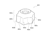
あるいは、図7に例示した第2変形例の煮零れ汁カバー423のように、拡張部423aではなく、垂下部423bに流下溝423cを形成しても良い。このような第2変形例においても、煮零れ汁は、流下溝423cと流下溝423cとの間に形成された峰部423dを避けて、流下溝423cを流下することとなり、最終的に煮零れ汁が滴下する位置を限定することができる。図8には、第2変形例の煮零れ汁カバー423で最終的に煮零れ汁が滴下する位置を限定することができる理由が示されている。
Or you may form the descent | fall groove |
第2変形例の煮零れ汁カバー423においても、煮零れが生じた直後のように大量の煮零れ汁が流下している間は、図8(a)に示したように、煮零れ汁カバー423の上を万遍なく煮零れ汁が流下していく。ところが、流下する煮零れ汁が少なくなってくると、煮零れ汁は、図8(b)に示したように、峰部423dを避けて流下溝423cから流下するようになり、更に煮零れ汁が少なくなると、図8(c)に示したように、煮零れ汁はもっぱら流下溝423cから滴下するようになる。その結果、最終的には、滴下には到らない分量の煮零れ汁が、流下溝423cの下端に付着した状態となって、図8(d)に示したように、その位置で煮零れ汁が固化することになる。
Also in the boiled
このように、第2変形例の煮零れ汁カバー423でも、煮零れ汁の固化が生じる位置が流下溝123cの下端に限定される。このため、コンロバーナー10を長期に亘って使用しても、それ以外の部分では煮零れ汁の固化によって空気供給通路10aとの隙間が狭められることがなく、燃焼状態の悪化を回避することが可能となる。
Thus, also in the boiled
以上、本実施例および変形例について説明したが、本発明は上記の実施例および変形例に限られるものではなく、その要旨を逸脱しない範囲において種々の態様で実施することが可能である。 As mentioned above, although the present Example and the modification were demonstrated, this invention is not limited to said Example and a modification, It is possible to implement in a various aspect in the range which does not deviate from the summary.
1…ガスコンロ、 2…天板、 3…五徳、 4…バーナー用開口、
10…コンロバーナー、 10a…空気供給通路、 11…バーナーボディ、
12…混合管、 13…バーナーヘッド、 14…バーナーキャップ、
15…点火プラグ、 100…温度検出装置、 110…温度検出部、
111…集熱部、 112…センサー収納部、 113…温度センサー、
115…接着剤、 120…ホルダー、 121…コイルバネ、
122…バネ受け、 123…煮零れ汁カバー、 123a…拡張部、
123b…垂下部、 123c…流下溝、 123d…峰部、
130…支持パイプ、 200…温度検出装置、 223…煮零れ汁カバー、
323…煮零れ汁カバー、 323c…流下溝、 423…煮零れ汁カバー、
423c…流下溝、 423d…峰部。
1 ... Gas stove, 2 ... Top plate, 3 ... Gotoku, 4 ... Opening for burner,
10 ... a stove burner, 10a ... an air supply passage, 11 ... a burner body,
12 ... Mixing tube, 13 ... Burner head, 14 ... Burner cap,
15 ... Spark plug, 100 ... Temperature detector, 110 ... Temperature detector,
111 ... Heat collecting part, 112 ... Sensor storage part, 113 ... Temperature sensor,
115 ... Adhesive, 120 ... Holder, 121 ... Coil spring,
122 ... Spring holder, 123 ... Boiled soup cover, 123a ... Expansion part,
123b ... drooping part, 123c ... descent groove, 123d ... peak part,
130 ... support pipe, 200 ... temperature detector, 223 ... boiled juice cover,
323 ... Boiled soup cover, 323c ... Downflow ditch, 423 ... Boiled soup cover,
423c ... Downflow groove, 423d ... Peak.
Claims (3)
前記空気供給通路内に立設された支持パイプと、
略筒形状に形成されて、上下方向に移動可能な態様で下端側が前記支持パイプに嵌め込まれたホルダーと、
前記ホルダーの上端に取り付けられた集熱部と、
該集熱部の内部に取り付けられた温度センサーと、
前記ホルダーを上方に付勢するコイルバネと、
前記ホルダーの外周に取り付けられて前記調理容器からの煮零れ汁が外側表面を流下することにより、該煮零れ汁が該ホルダーの下端にかかることを防止する煮零れ汁カバーと
を備え、
前記煮零れ汁カバーの前記外側表面は、前記煮零れ汁が流下する経路の少なくとも一部が溝形状に形成されている
ことを特徴とする温度検出装置。 In the temperature detection device for detecting the temperature of the cooking container placed on the virtues, the air supply passage through which the secondary air is supplied is provided in the stove burner formed through the center,
A support pipe erected in the air supply passage;
A holder that is formed in a substantially cylindrical shape and is fitted in the support pipe at the lower end side in a manner movable in the vertical direction;
A heat collecting part attached to the upper end of the holder;
A temperature sensor attached to the inside of the heat collecting unit;
A coil spring for urging the holder upward;
A boiled juice cover that is attached to the outer periphery of the holder and prevents the boiled juice from falling on the lower end of the holder by flowing down the outer surface of the boiled juice from the cooking container;
At least a part of a path along which the boiled juice flows down is formed in a groove shape on the outer surface of the boiled juice cover.
前記煮零れ汁カバーの前記外側表面には、該煮零れ汁カバーの周方向に沿って複数の前記溝形状が等間隔に形成されている
ことを特徴とする温度検出装置。 The temperature detection device according to claim 1,
The temperature detecting device, wherein a plurality of groove shapes are formed at equal intervals along the circumferential direction of the boiled soup cover on the outer surface of the boiled soup cover.
前記煮零れ汁カバーは、下方に向けて広がる形状の拡張部を有しており、該拡張部の少なくとも一部に前記溝形状が形成されている
ことを特徴とする温度検出装置。 In the temperature detection device according to claim 1 or 2,
The boiled soup cover has an extended portion having a shape extending downward, and the groove shape is formed in at least a part of the extended portion.
Priority Applications (2)
| Application Number | Priority Date | Filing Date | Title |
|---|---|---|---|
| JP2014249917A JP2016109397A (en) | 2014-12-10 | 2014-12-10 | Temperature detection device |
| KR1020150173849A KR20160070694A (en) | 2014-12-10 | 2015-12-08 | Temperature Detecting Apparatus |
Applications Claiming Priority (1)
| Application Number | Priority Date | Filing Date | Title |
|---|---|---|---|
| JP2014249917A JP2016109397A (en) | 2014-12-10 | 2014-12-10 | Temperature detection device |
Publications (1)
| Publication Number | Publication Date |
|---|---|
| JP2016109397A true JP2016109397A (en) | 2016-06-20 |
Family
ID=56123797
Family Applications (1)
| Application Number | Title | Priority Date | Filing Date |
|---|---|---|---|
| JP2014249917A Pending JP2016109397A (en) | 2014-12-10 | 2014-12-10 | Temperature detection device |
Country Status (2)
| Country | Link |
|---|---|
| JP (1) | JP2016109397A (en) |
| KR (1) | KR20160070694A (en) |
Cited By (1)
| Publication number | Priority date | Publication date | Assignee | Title |
|---|---|---|---|---|
| JP2016109393A (en) * | 2014-12-10 | 2016-06-20 | リンナイ株式会社 | Temperature detection device |
Citations (4)
| Publication number | Priority date | Publication date | Assignee | Title |
|---|---|---|---|---|
| JPS61156802U (en) * | 1985-03-20 | 1986-09-29 | ||
| JPS61162702U (en) * | 1985-03-29 | 1986-10-08 | ||
| JP2007139312A (en) * | 2005-11-18 | 2007-06-07 | Matsushita Electric Ind Co Ltd | Cooking stove burner |
| JP2013044468A (en) * | 2011-08-24 | 2013-03-04 | Tateyama Kagaku Sensor Technology Co Ltd | Temperature detector for cooking utensil |
-
2014
- 2014-12-10 JP JP2014249917A patent/JP2016109397A/en active Pending
-
2015
- 2015-12-08 KR KR1020150173849A patent/KR20160070694A/en unknown
Patent Citations (4)
| Publication number | Priority date | Publication date | Assignee | Title |
|---|---|---|---|---|
| JPS61156802U (en) * | 1985-03-20 | 1986-09-29 | ||
| JPS61162702U (en) * | 1985-03-29 | 1986-10-08 | ||
| JP2007139312A (en) * | 2005-11-18 | 2007-06-07 | Matsushita Electric Ind Co Ltd | Cooking stove burner |
| JP2013044468A (en) * | 2011-08-24 | 2013-03-04 | Tateyama Kagaku Sensor Technology Co Ltd | Temperature detector for cooking utensil |
Cited By (1)
| Publication number | Priority date | Publication date | Assignee | Title |
|---|---|---|---|---|
| JP2016109393A (en) * | 2014-12-10 | 2016-06-20 | リンナイ株式会社 | Temperature detection device |
Also Published As
| Publication number | Publication date |
|---|---|
| KR20160070694A (en) | 2016-06-20 |
Similar Documents
| Publication | Publication Date | Title |
|---|---|---|
| JP5204198B2 (en) | Gas stove | |
| JP5774412B2 (en) | Temperature detector for cooking utensils | |
| EP3195765B1 (en) | On-board coffee processor | |
| JP6025809B2 (en) | Temperature detection device | |
| JP2016109397A (en) | Temperature detection device | |
| CN105832147A (en) | Multifunctional kettle | |
| JP6104878B2 (en) | Temperature detection device | |
| JP6152524B2 (en) | Temperature detection device | |
| US1554612A (en) | Coffee-urn cover | |
| JP6271467B2 (en) | Temperature detection device | |
| JP6152525B2 (en) | Temperature detection device | |
| JP6114992B2 (en) | Stove burner | |
| US2785276A (en) | Heating unit for percolator | |
| KR20160018370A (en) | Temperature detector | |
| JP5312084B2 (en) | Gas stove | |
| KR101830087B1 (en) | Apparatus for preventing over-heating for gas range | |
| KR101320006B1 (en) | Apparatus for preventing over-heating for gas range | |
| JP2005345024A (en) | Pan bottom temperature sensor | |
| KR101722134B1 (en) | Burner for gas range | |
| JPS5828927A (en) | Thermosensor for use with portable cooking stove | |
| JPH07269871A (en) | Pan bottom temperature sensing device of gas cooking device | |
| JP5946778B2 (en) | Stove burner | |
| US1978904A (en) | Liquid fuel burner | |
| EP3919818A1 (en) | Energy gathering cover of gas cooktop, pot holder of gas cooktop, and gas cooktop | |
| CN209763070U (en) | Single-ring stove burner |
Legal Events
| Date | Code | Title | Description |
|---|---|---|---|
| A977 | Report on retrieval |
Free format text: JAPANESE INTERMEDIATE CODE: A971007 Effective date: 20160907 |
|
| A131 | Notification of reasons for refusal |
Free format text: JAPANESE INTERMEDIATE CODE: A131 Effective date: 20160913 |
|
| A521 | Written amendment |
Free format text: JAPANESE INTERMEDIATE CODE: A523 Effective date: 20161111 |
|
| A02 | Decision of refusal |
Free format text: JAPANESE INTERMEDIATE CODE: A02 Effective date: 20170411 |