JP2016106946A - Respiratory function test apparatus - Google Patents
Respiratory function test apparatus Download PDFInfo
- Publication number
- JP2016106946A JP2016106946A JP2014249153A JP2014249153A JP2016106946A JP 2016106946 A JP2016106946 A JP 2016106946A JP 2014249153 A JP2014249153 A JP 2014249153A JP 2014249153 A JP2014249153 A JP 2014249153A JP 2016106946 A JP2016106946 A JP 2016106946A
- Authority
- JP
- Japan
- Prior art keywords
- storage case
- respiratory function
- testing device
- function testing
- joint
- Prior art date
- Legal status (The legal status is an assumption and is not a legal conclusion. Google has not performed a legal analysis and makes no representation as to the accuracy of the status listed.)
- Granted
Links
Images

Landscapes
- Measurement Of The Respiration, Hearing Ability, Form, And Blood Characteristics Of Living Organisms (AREA)
Abstract
【課題】製造誤差や取り付け誤差があっても、吸収剤収納ケースの着脱が容易で、接続部の漏れがなく確実に接続するようにした呼吸機能検査装置を提供する。
【解決手段】凹部18に収納ケース5をさらに挿入すると、リップ部65A、65Bの右端が矢印66方向にさらに倒れて、雌継手71A、71Bの内周面74A、74Bにリップ部65A、65Bの右端が線接触する。雌継手71A、71Bや雄継手61A、61Bの製造誤差や取り付け誤差があっても、リップ部65A、65Bの右端が、線接触状態を維持したままで矢印66方向に倒れて誤差を吸収する。
【選択図】図5Provided is a respiratory function testing device in which an absorbent case can be easily attached and detached even if there is a manufacturing error or an attachment error, and a connection portion is securely connected without leakage.
When the storage case 5 is further inserted into the recess 18, the right ends of the lip portions 65A, 65B are further tilted in the direction of the arrow 66, and the lip portions 65A, 65B of the female joints 71A, 71B are placed on the inner peripheral surfaces 74A, 74B. The right end makes line contact. Even if there is a manufacturing error or attachment error of the female joints 71A and 71B and the male joints 61A and 61B, the right ends of the lip portions 65A and 65B fall in the direction of the arrow 66 while maintaining the line contact state to absorb the error.
[Selection] Figure 5
Description
本発明は、被験者から呼吸経路に呼出される二酸化炭素ガスを吸収する吸収剤を収納した収納ケースを備える呼吸機能検査装置に関する。 The present invention relates to a respiratory function testing device including a storage case that stores an absorbent that absorbs carbon dioxide gas called from a subject to a respiratory path.
従来より、特許文献1に示す呼吸機能検査装置のように、被験者から呼吸経路に呼出される二酸化炭素ガスを吸収剤(ソーダライム)に吸収させつつ呼吸機能を検査する呼吸機能検査装置が提案されている。 2. Description of the Related Art Conventionally, a respiratory function testing device that tests respiratory function while absorbing carbon dioxide gas called by a subject to the respiratory route in an absorbent (soda lime) has been proposed, as in the respiratory function testing device shown in Patent Document 1. ing.
そして、このような呼吸機能検査装置として、吸収剤を交換可能とするために、吸収剤を収納した収納ケースごと交換するようにしたものがある。しかしながら、このような収納ケースは呼吸経路に設けられるものであるため、呼吸機能検査に影響を及ぼすこと無くその交換を容易化することが困難であった。 And as such a respiratory function test | inspection apparatus, in order to be able to replace | exchange an absorbent, there exists what changed the whole storage case which accommodated the absorbent. However, since such a storage case is provided in the respiratory path, it is difficult to facilitate replacement without affecting the respiratory function test.
本発明の目的は、呼吸機能の検査に影響を及ぼすことなく容易に収納ケースを交換可能な呼吸機能検査装置を提供することにある。 An object of the present invention is to provide a respiratory function test apparatus that can easily replace a storage case without affecting the test of the respiratory function.
前記課題は以下の手段によって解決される。
すなわち、手段1の呼吸機能検査装置は、
被験者の呼吸機能を検査する呼吸機能検査装置(1)であって、
前記呼吸機能検査装置の本体部(11)には、二酸化炭素ガスを吸収する吸収剤(51)を収納した収納ケース(5)を呼吸経路に接続するための接続部(凹部18)が設けられ、
前記接続部は円筒状の雌継手(71A,71B)を有しており、
前記収納ケースは前記雌継手に挿入されて内嵌する円筒状の雄継手(61A,61B)を備え、
前記雄継手は弾性部材で形成され、
前記雄継手の一端は前記収納ケースに固定され、
前記雄継手の他端は前記収納ケースから突出してその外周面(64A,64B)が前記雌継手の内周面(74A,74B)に内嵌し、
前記雄継手の他端外周面には、前記雄継手の外周面から半径方向外側に突出し、前記雄継手の他端側から一端側に向かって斜めに拡径するとともに、前記雌継手の内周面に線接触するリップ部(65A,65B)が形成されている
ことを特徴とする。
本手段によれば、呼吸機能の検査に影響を及ぼすことなく容易に収納ケースを交換可能とすることができる。
The said subject is solved by the following means.
That is, the respiratory function testing device of means 1 is
A respiratory function testing device (1) for testing a subject's respiratory function,
The body part (11) of the respiratory function testing device is provided with a connection part (concave part 18) for connecting a storage case (5) containing an absorbent (51) for absorbing carbon dioxide gas to the respiratory path. ,
The connecting portion has a cylindrical female joint (71A, 71B),
The storage case includes a cylindrical male joint (61A, 61B) that is inserted into the female joint and fits therein.
The male joint is formed of an elastic member,
One end of the male joint is fixed to the storage case,
The other end of the male joint protrudes from the storage case, and its outer peripheral surface (64A, 64B) is fitted into the inner peripheral surface (74A, 74B) of the female joint,
The other outer peripheral surface of the male joint protrudes radially outward from the outer peripheral surface of the male joint, and the diameter of the male joint is increased obliquely from the other end side to the one end side. A lip portion (65A, 65B) that makes line contact with the surface is formed.
According to this means, the storage case can be easily replaced without affecting the examination of the respiratory function.
手段2の呼吸機能検査装置は、
手段1に記載した呼吸機能検査装置であって、
前記雌継手の内径は、前記雄継手が内嵌している状態における該雄継手の他端側から一端側に向かって縮径しない
ことを特徴とする。
本手段によれば、収納ケースを本体部から容易に取り外すことができる。
The respiratory function testing device of means 2 is:
A respiratory function testing device described in means 1,
The inner diameter of the female joint is not reduced from the other end side to the one end side of the male joint when the male joint is fitted therein.
According to this means, the storage case can be easily detached from the main body.
手段3の呼吸機能検査装置は、
手段2に記載した呼吸機能検査装置であって、
前記接続部は、前記呼吸機能検査装置の本体部(11)の側面に形成された凹部(18)であり、
前記凹部は、前記収納ケースの底面(531)が載置されて前記収納ケースの下向きの荷重を支持する荷重支持面(181)を有し、
前記荷重支持面には、前記収納ケースの挿入方向に平行に形成された第1の案内レール(182)が設けられ、
前記収納ケースの底面には、前記収納ケースの挿入方向に平行に形成され、前記第1の案内レールに係合する案内溝(532)が設けられている
ことを特徴とする。
本手段によれば、収納ケースを本体部と着脱する際の操作が容易となる。
The respiratory function testing device of means 3 is:
A respiratory function testing device described in means 2,
The connection portion is a recess (18) formed on a side surface of the body portion (11) of the respiratory function testing device,
The recess has a load support surface (181) on which a bottom surface (531) of the storage case is placed and supports a downward load of the storage case,
The load support surface is provided with a first guide rail (182) formed in parallel with the insertion direction of the storage case,
A guide groove (532) that is formed in parallel to the insertion direction of the storage case and engages with the first guide rail is provided on the bottom surface of the storage case.
According to this means, the operation when the storage case is attached to and detached from the main body is facilitated.
手段4の呼吸機能検査装置は、
手段3に記載した呼吸機能検査装置であって、
前記凹部の上面(183)には、前記収納ケースの挿入方向に平行に形成された第2の案内レール(184)が設けられ、
前記収納ケース5の上部(上板52)には、前記第2の案内レールに係合する係合突起(523)が形成されている
ことを特徴とする。
本手段によれば、収納ケースを本体部と着脱する際の操作が容易となる。
The respiratory function testing device of means 4 is:
A respiratory function testing device described in means 3,
A second guide rail (184) formed in parallel with the insertion direction of the storage case is provided on the upper surface (183) of the recess,
An engagement protrusion (523) that engages with the second guide rail is formed on the upper portion (upper plate 52) of the
According to this means, the operation when the storage case is attached to and detached from the main body is facilitated.
手段5の呼吸機能検査装置は、
手段3又は4に記載した呼吸機能検査装置であって、
前記凹部は、
前記呼吸機能検査装置の本体部に開閉可能に取り付けられ、呼吸空間を遮蔽する開閉扉(17)の側面に形成されている
ことを特徴とする。
本手段によれば、開閉扉のスペースを有効に活用して本体部の大型化を抑止することができる。
The respiratory function testing device of
A respiratory function testing device according to means 3 or 4,
The recess is
It is attached to the main body of the respiratory function testing device so as to be openable and closable, and is formed on a side surface of an open / close door (17) that shields a respiratory space.
According to this means, it is possible to suppress the enlargement of the main body by effectively utilizing the space of the door.
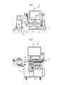
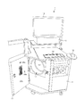
以下、本実施形態の呼吸機能検査装置を図面に基づいて説明する。図1は本実施形態の呼吸機能検査装置の外観を示し、(a)は正面図、(b)は(a)の平面図である。図2は図1の呼吸機能検査装置の開閉扉を開いた状態を示す斜視図である。図1、図2に示すように、本発明の呼吸機能検査装置1は、筐体である本体部11と、本体部11に内蔵されたローリングシール型スパイロメータ12等から構成される。本体部11の上面には、キーボード13、CRT14、プリンタ15、マウス16が載置され、本体部11の内部には制御部(図示せず)が備えられている。本体部11の左側面には、開閉扉17が蝶番によって開閉可能に取り付けられ、開閉扉17を閉じてローリングシール型スパイロメータ12を遮蔽する。
Hereinafter, the respiratory function testing device of this embodiment will be described with reference to the drawings. FIG. 1 shows the external appearance of the respiratory function testing device of the present embodiment, where (a) is a front view and (b) is a plan view of (a). FIG. 2 is a perspective view showing a state in which the open / close door of the respiratory function test apparatus of FIG. 1 is opened. As shown in FIGS. 1 and 2, the respiratory function testing device 1 of the present invention includes a
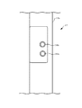
図1に示すように、開閉扉17の側面には上下方向に長い凹部18が形成され、この凹部18に本発明の収納ケースが着脱可能に取り付けられる。また、図1及び図3に示すように、開閉扉17の外壁17bには、凹部18と対向する位置に吸気チューブ接続口38b、呼気チューブ接続口39bがそれぞれ設けられている。また、図2に示すように、開閉扉17の内壁17aには、吸気口38a、呼気口39aがそれぞれ設けられている。
As shown in FIG. 1, a
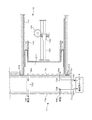
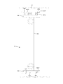
図4は本実施形態の呼吸機能検査装置1のローリングシール型スパイロメータ12周辺の概略の構造を示す説明図である。図4に示すように、ローリングシール型スパイロメータ12は、円筒状のシリンダ121と、軸受け用のスライドベアリング122により支持されるピストン123を備え、シリンダ121とピストン123との間をシリコン製のローリングシール124で密閉している。ローリングシール124の一端はシリンダ121の内壁面に接合され、他端はピストン123の側面に接合されている。ピストン123の移動に追随してローリングシール124が湾曲することで、シリンダ121とピストン123との隙間の密閉状態が維持される。ピストン123が移動すると、ポテンショメータ125でピストン123の中心軸126の軸方向の移動距離を検出する。
FIG. 4 is an explanatory diagram showing a schematic structure around the rolling
図2及び図4に示すように、シリンダ121の開口部周囲の壁面には、シリコン製のクッション部材212が接合されており、シリンダ121の開口部が、環状のクッション部材212によって囲まれる構成となっている。図4に示すように、クッション部材212は、開閉扉17が閉じられると、開閉扉17の内壁17aと接触して変形することにより、開閉扉17を閉じたときの衝撃を緩和する。また、クッション部材212は、開閉扉17の内壁aと密着することにより、開閉扉17の内壁17aとシリンダ121の開口部周囲の壁面との隙間を埋める。これにより、開閉扉17の内壁17aとクッション部材212とによって、シリンダ121内のシリンダ室211が密閉される。被験者の吸気時には、シリンダ室211のガスが被験者に供給され(被験者がシリンダ室211のガスを吸入し)、被験者の呼気時には、被験者の呼気がシリンダ室211に吐出される。即ち、開閉扉17が閉じられたときのシリンダ室211は、被験者の呼吸空間として機能する。
As shown in FIGS. 2 and 4, a
図4に示すように、開閉扉17の内壁17aには、吸気口38a、呼気口39aが設けられている。また、開閉扉17の外壁17bには、吸気チューブ接続口38b、呼気チューブ接続口39bが設けられている。吸気口38aには、ゴムチューブ73Cの一端が接続され、吸気チューブ接続口38bには、ゴムチューブ73Cの他端が接続されている。即ち、ゴムチューブ73Cによりシリンダ室211から本体外部に吸気を通過させるための、呼気口39aから吸気チューブ接続口38bに連なる吸気経路が形成されている。
As shown in FIG. 4, the
また、呼気口39aには、ゴムチューブ73Aの一端が接続され、図5に示すように、凹部18に設けられた本体部側流入口72Aには、ゴムチューブ73Aの他端が接続されている。また、図5に示すように、凹部18に設けられた本体部側流出口72Bには、ゴムチューブ73Bの一端が接続され、呼気チューブ接続口39bには、ゴムチューブ73Bの他端が接続されている。そして、後述するように、本体部側流出口72Bには、収納ケース5の収納ケース側流入口63Bが流体的に接続され、本体部側流入口72Aには、収納ケース5の収納ケース側流出口63Aが流体的に接続されることにより、収納ケース5が凹部18に接続されたときに、本体部側流出口72Bと本体部側流入口72Aとが、収納ケース5(収納ケース5内の吸収剤51)を介して流体的に接続されることになる。即ち、ゴムチューブ73A及び73B、並びにこれらと接続される収納ケース5により、本体外部からシリンダ室211に呼気を通過させるための、呼気チューブ接続口39bから呼気口39aに連なる呼気経路が形成されている。
One end of the
開閉扉17の外壁17bに設けられた吸気チューブ接続口38bに接続された呼吸チューブを介して被験者が吸気を行うと、ピストン123が手前方向(開口部方向)に移動してシリンダ室211の容量(呼吸空間の体積)が減少すると共に、シリンダ室211内のガスが吸気口38aから外部に流出し、吸気チューブを介して被験者に供給される。このときのピストン123の移動距離をポテンショメータ125が検出することにより、吸気量が電気信号に変換される。また、呼気チューブ接続口39bに接続された呼気チューブを介して被験者が呼気を行うと、被験者の呼気は、呼気チューブ接続口39bから収納ケース5に到達し、収納ケース5を通過する際に吸収剤51により二酸化炭素ガスが吸収され、さらに呼気口39aからシリンダ室211に吐出される。これに伴い、ピストン123が奥方向(開口部と反対方向)に移動してシリンダ室211の容量(呼吸空間の体積)が増加する。このときのピストン123の移動距離をポテンショメータ125が検出することにより、呼気量が電気信号に変換される。ポテンショメータ125の電気信号は本体部11内部の制御部に送られ、図示しないCPUで演算されて、CRT14に表示され、プリンタ15でプリントアウトされて、医師や検査技師等に通知される。
When the subject inhales through the breathing tube connected to the intake
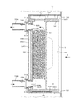
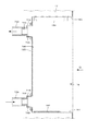
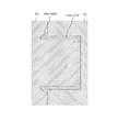
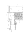
図5は図1の呼吸機能検査装置1の本体部の側面に装着された本発明の収納ケースを示す縦断面図、図6は図5のP矢視図である。図7は収納ケースを取り外した状態を示す呼吸機能検査装置1の本体部の側面の縦断面図、図8は図7のQ矢視図である。図5から図8に示すように、本発明の収納ケース5は、上下方向に長い直方体の箱で、透明なアクリル樹脂で成形され、内部に二酸化炭素ガスを吸収する吸収剤51が収納されている。収納ケース5の上板52にはふた521がねじ込まれ、ふた521を取り外して吸収剤51を交換する。
FIG. 5 is a longitudinal sectional view showing the storage case of the present invention mounted on the side surface of the main body of the respiratory function testing device 1 of FIG. 1, and FIG. 6 is a view taken in the direction of arrow P in FIG. FIG. 7 is a longitudinal sectional view of the side surface of the main body of the respiratory function testing device 1 showing a state in which the storage case is removed, and FIG. 8 is a view taken in the direction of the arrow Q in FIG. As shown in FIGS. 5 to 8, the
開閉扉17の凹部18の下面として、開閉扉17の外壁17bよりも内壁17a側に入り込んだ側面186の下端から水平方向に突出して本体部11の表面位置に到る荷重支持面181が形成され、この荷重支持面181に収納ケース5の底板53の底面531が載置されて収納ケース5の下向きの荷重が支持される。荷重支持面181には、収納ケース5の挿入方向(図5、図7の左右方向)に平行に断面矩形で棒状の案内レール182がボルトで固定されている。収納ケース5の底面531には、案内レール182に係合する案内溝532が形成され、凹部18に対して収納ケース5下部の挿入位置(図6の左右方向)を位置決めする。案内溝532は、底板53の左端面(図5で見て)に開口している。
As a lower surface of the
凹部18の上面183は、収納ケース5の上板52の上面522との間に隙間を有して形成されている。凹部18の上面183には、収納ケース5の挿入方向(図5、図7の左右方向)に平行に断面矩形で棒状の案内レール184がボルトで固定されている。収納ケース5の上板52には、案内レール184に係合する断面矩形の係合突起523が形成され、凹部18に対して収納ケース5上部の挿入位置(図6の左右方向)を位置決めする。
The
収納ケース5の側板54の側面541の上部と下部には、中空円筒状の雄継手61A、61Bが側板54の側面541から突出して固定されている。雄継手61A、61Bは、シリコンゴム等の耐油性に優れた弾性部材で成型されている。雄継手61A、61Bの右端(一端)は、側板54にねじ込まれた中空円筒状のナット62A、62Bによって側板54に固定されている。雄継手61Aと61B、ナット62Aと62Bは同一形状で、ナット62Aには、呼気が収納ケース5から流出する収納ケース側流出口63Aが形成され、ナット62Bには、呼気が収納ケース5に流入する収納ケース側流入口63Bが形成されている。
Hollow cylindrical male joints 61 </ b> A and 61 </ b> B protrude from the
また、凹部18の側板185の上部と下部には、中空円筒状の雌継手71A、71Bが側板185にボルトで固定され、雄継手61A、61Bの左端(他端)が雌継手71A、71の内周面74A、74Bに内嵌している。雌継手71Aには、呼気が本体部に流入する本体部側流入口72Aが形成され、雌継手71Bには、呼気が本体部から流出する本体部側流出口72Bが形成されている。本体部側流入口72Aと本体部側流出口72Bは、側板185の側面186に開口している。雌継手71A、71Bは同一形状で、表面が滑らかで、強度があるポリアセタール樹脂で形成されている。雌継手71A、71Bの左端には、ゴムチューブ73A、73Bが接続され、ゴムチューブ73A、73Bは呼吸機能検査装置1の呼吸経路に接続されている。
Further, hollow cylindrical
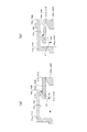
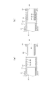
図9は、本発明の呼吸機能検査装置の雌継手71A、71Bと雄継手61A、61Bの接合部を示し、(a)は雌継手71A、71Bに対して雄継手61A、61Bの挿入を開始した状態を示す拡大縦断面図、(b)は雌継手71A、71Bに対して雄継手61A、61Bの挿入が完了した状態を示す拡大縦断面図である。図9に示すように、雄継手61A、61Bの左端(他端)には、雄継手61A、61Bの外周面64A、64Bから半径方向外側に突出するリップ部65A、65Bが環状に形成されている。リップ部65A、65Bは、雄継手61A、61Bの左端(他端)側から右端(一端)側に向かって斜めに拡径するとともに、その右端(一端)側が雌継手71A、71Bの内周面74A、74Bに線接触するくさび形状に形成されている。
FIG. 9 shows a joint between the
雄継手61A、61Bの自由状態では、雌継手71A、71Bの内周面74A、74Bの内径寸法よりも、リップ部65A、65Bの右端の外径寸法が大きく形成されている。雌継手71A、71Bの内周面74A、74Bの右端には、面取り部75A、75Bが形成されている。雄継手61A、61Bの自由状態では、雌継手71A、71Bの内周面74A、74Bの右端(面取り部75A、75Bの右端)の内径寸法は、リップ部65A、65Bの右端の外径寸法よりも大きく形成されている。すなわち、面取り部75A、75Bの左端から右端にかけて拡径する構成において、その左端(内周面74A、74Bとの境界)の内径はリップ部65A、65Bの外径より小さく、その右端(開口端)の内径はリップ部65A、65Bの外径より大きい。
In the free state of the
収納ケース5の取っ手55を手で持って、開閉扉17の凹部18に収納ケース5を挿入すると、凹部18の案内レール182、184に案内されて収納ケース5は凹部18に正確に位置決めされる。収納ケース5を凹部18に挿入すると、図9(a)に示すように、凹部18の雌継手71A、71Bに収納ケース5の雄継手61A、61Bが挿入される。すると、雌継手71A、71Bの面取り部75A、75Bに雄継手61A、61Bのリップ部65A、65Bの右端が当接する。凹部18に収納ケース5をさらに挿入すると、リップ部65A、65Bの右端が矢印66方向に倒れるとともに、雄継手61A、61Bの左端が矢印67方向に若干縮径する。
Holding the
図9(b)に示すように、凹部18に収納ケース5をさらに挿入すると、リップ部65A、65Bの右端が矢印66方向にさらに倒れて、雌継手71A、71Bの内周面74A、74Bにリップ部65A、65Bの右端が線接触する。雌継手71A、71Bや雄継手61A、61Bの製造誤差や取り付け誤差があっても、リップ部65A、65Bの右端が、線接触状態を維持したままで矢印66方向に倒れて誤差を吸収する。従って、継手接続部の漏れがなく、挿入抵抗が小さいため、収納ケース5を容易に着脱できることができる。
As shown in FIG. 9 (b), when the
また、リップ部65A、65Bの右端が雌継手71A、71Bの内周面74A、74Bに引っ掛かるため、振動等により収納ケース5が凹部18から抜け出すことを防止することができる。また、凹部18から収納ケース5を取り外す場合には、収納ケース5の取っ手55を手で持って、案内レール182、184に沿った方向に引き抜くことにより、雌継手71A、71Bの内周面74A、74Bをリップ部65A、65Bの右端が摺動して、引っかかりや過度の抵抗を感じる無く凹部18から収納ケース5を容易に取り外すことができる。ここで、雌継手71A、71Bの内周面74A、74Bの左端から右端(面取り部75A、75Bの右端)にかけて内径寸法は縮小しない構成となっているため、凹部18から収納ケース5を容易に取り外すことができるとともに、収納ケース5を取り外した状態での内周面74A、74Bの清掃等も容易である。
Further, since the right ends of the
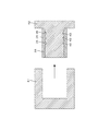
図10は、本実施形態の雄継手61A、61Bを成形する金型を示す拡大縦断面図である。図10に示すように、本発明の雄継手61A、61Bは、雌金型81と雄金型82を使用してを製造する。本発明の雄継手61A、61Bを製造する雌金型81と雄金型82は逆テーパがないため、雄継手61A、61Bを雌金型81と雄金型82から外すのが容易で、作業時間を短縮できるため製造コストを低減することができる。
FIG. 10 is an enlarged longitudinal sectional view showing a mold for molding the
呼吸経路中の二酸化炭素ガスを吸収する吸収剤を収納した収納ケースは、二酸化炭素ガスの吸収効率を確保するために、吸収剤を多く収納可能なように大型の収納ケースを使用している。この収納ケースは、吸収剤を交換するために呼吸機能検査装置の本体部から着脱する必要があるが、大型であるため、本体部の呼吸経路の接続口に漏れがなく容易に着脱できることが困難であった。上記実施形態に示した開閉扉17の凹部18と収納ケース5の着脱機構により、呼吸経路との漏れの無い接合が可能であり、且つ開閉扉17と容易に着脱可能となる。
A storage case storing an absorbent that absorbs carbon dioxide gas in the respiratory path uses a large storage case so that a large amount of absorbent can be stored in order to ensure the absorption efficiency of carbon dioxide gas. This storage case needs to be attached / detached from the body part of the respiratory function testing device in order to replace the absorbent, but since it is large, it is difficult to attach and detach easily without leakage at the connection port of the respiratory path of the body part Met. The
また、この実施形態では、凹部18の荷重支持面181に設けられた案内レール182及び収納ケース5の底面531に設けられた案内溝532、並びに、凹部18の上面183に設けられた案内レール184及び収納ケース5の上板52に設けられた係合突起523により、凹部18に収納ケース5を接続する際の位置決めが容易である。また、凹部18から収納ケース5を引き抜く際にも、引き抜く方向が規定され、引っかかりや過度の抵抗を感じることなく容易に収納ケース5を離脱させることができる。さらに、この実施形態では、開閉扉17の外壁17bよりも内壁17a側に入り込んだ凹部18に収納ケース5を設置可能であるため、本体部11を省スペース化することが可能である。
Further, in this embodiment, the
[比較例]
図11は、比較例に係る呼吸機能検査装置の本体部の側面に装着された収納ケースの雄継手と本体部の雌継手の接合部周辺を示す縦断面図、図12は、図11の雌継手と雄継手の接合部を示し、(a)は雌継手に対して雄継手の挿入を開始した状態を示す拡大縦断面図、(b)は雌継手に対して雄継手の挿入が完了した状態を示す拡大縦断面図である。図11に示すように、収納ケース21は上下方向に長い直方体の箱で、透明なアクリル樹脂で形成され、その内部空間に二酸化炭素ガスを吸収する吸収剤22を収納している。収納ケース21の上板27にはふた271がねじ込まれ、ふた271を取り外して吸収剤22を交換する。収納ケース21の側面23には、中空円筒状の雄継手24が側面23から左方に突出して形成されている。雄継手24の内周面には、呼気が収納ケース21から本体部に流出する収納ケース側流出口25が形成されている。
[Comparative example]
FIG. 11 is a longitudinal sectional view showing the periphery of the joint between the male joint of the storage case and the female joint of the main body mounted on the side surface of the main body of the respiratory function testing device according to the comparative example, and FIG. 12 is the female of FIG. The joint of a joint and a male joint is shown, (a) is an enlarged vertical sectional view showing a state in which insertion of a male joint is started with respect to a female joint, and (b) is completed with insertion of a male joint into a female joint. It is an enlarged vertical sectional view showing a state. As shown in FIG. 11, the
呼吸機能検査装置の本体部側の側面には、円筒状の配管31が取り付けられ、配管31の内周面には、呼気が収納ケース21から本体部に流入する本体部側流入口32が形成されている。配管31の右端外周面には、弾性部材で形成された円筒状の雌継手33の左端がきつく外嵌して固定され、雌継手33の右端の内周面34が雄継手24の外周面26に外嵌している。図12(a)に示すように、雌継手33の内周面34には、3個の環状突起35が形成されている。環状突起35は、断面が半円状で、雌継手33の内周面34から半径方向内側に突出している。環状突起35の内径寸法は、雄継手24の外周面26の外径寸法よりも多少小さく形成されていて、適度な締め代を付与している。
A
図12(b)に示すように、雌継手33に雄継手24を挿入すると、3個の環状突起35の接触面がつぶれて、雄継手24の外周面26と面接触する。その結果、外周面26と環状突起35との間の摩擦抵抗が増大し、雌継手33に雄継手24を挿入するのに大きな力が必要となる。また、雌継手33、雄継手24等の製造誤差によって、シールが不十分になることを防止するために、環状突起35と雄継手24の外周面26との間の締め代が大きくなるように製造することになるため、外周面26と環状突起35との間の摩擦抵抗が増大する傾向になる不具合もある。
As shown in FIG. 12B, when the male joint 24 is inserted into the female joint 33, the contact surfaces of the three
また、図13に示すように、従来の雌継手33は、雌金型41と雄金型42を使用して製造するが、雄金型42には、雌継手33の環状突起35を形成するために断面が半円状の環状溝43が形成されている。この環状溝43は、雄金型42から雌継手33を取り外す方向に対して逆テーパになるため、雌継手33を雄金型42から外しにくく、作業時間が長くなるため製造コストが上昇する。
As shown in FIG. 13, the conventional female joint 33 is manufactured using a
以上、本発明の実施の形態を説明したが、本発明はこの実施の形態に限定されることはない。本発明の目的、趣旨を逸脱しない範囲内での変更が可能なことはいうまでもない。 Although the embodiment of the present invention has been described above, the present invention is not limited to this embodiment. Needless to say, changes can be made without departing from the scope and spirit of the present invention.
1…呼吸機能検査装置
11…本体部
12…ローリングシール型スパイロメータ
13…キーボード
14…CRT
15…プリンタ
16…マウス
17…開閉扉
18…凹部
181…荷重支持面
182…案内レール
183…上面
184…案内レール
185…側板
186…側面
21…収納ケース
22…吸収剤
23…側面
24…雄継手
25…収納ケース側流出口
26…外周面
27…上板
271…ふた
31…配管
32…本体部側流入口
33…雌継手
34…内周面
35…環状突起
38a…吸気口
38b…吸気チューブ接続口
39a…呼気口
39b…呼気チューブ接続口
41…雌金型
42…雄金型
43…環状溝
5…収納ケース
51…吸収剤
52…上板
521…ふた
522…上面
523…係合突起
53…底板
531…底面
532…案内溝
54…側板
55…取っ手
541…側面
61A、61B…雄継手
62A、62B…ナット
63A…収納ケース側流出口
63B…収納ケース側流入口
64A、64B…外周面
65A、65B…リップ部
66、67…矢印
71A、71B…雌継手
72A…本体部側流入口
72B…本体部側流出口
73A、73B、73C…ゴムチューブ
74A、74B…内周面
75A、75B…面取り部
81…雌金型
82…雄金型
DESCRIPTION OF SYMBOLS 1 ... Respiratory
DESCRIPTION OF
Claims (5)
前記呼吸機能検査装置の本体部には、二酸化炭素ガスを吸収する吸収剤を収納した収納ケースを呼吸経路に接続するための接続部が設けられ、
前記接続部は円筒状の雌継手を有しており、
前記収納ケースは前記雌継手に挿入されて内嵌する円筒状の雄継手を備え、
前記雄継手は弾性部材で形成され、
前記雄継手の一端は前記収納ケースに固定され、
前記雄継手の他端は前記収納ケースから突出してその外周面が前記雌継手の内周面に内嵌し、
前記雄継手の他端外周面には、前記雄継手の外周面から半径方向外側に突出し、前記雄継手の他端側から一端側に向かって斜めに拡径するとともに、前記雌継手の内周面に線接触するリップ部が形成されている
ことを特徴とする呼吸機能検査装置。 A respiratory function testing device for testing a subject's respiratory function,
The main body part of the respiratory function testing device is provided with a connection part for connecting a storage case containing an absorbent that absorbs carbon dioxide gas to the respiratory path,
The connecting portion has a cylindrical female joint,
The storage case includes a cylindrical male joint that is inserted into and fitted into the female joint,
The male joint is formed of an elastic member,
One end of the male joint is fixed to the storage case,
The other end of the male joint protrudes from the storage case, and its outer peripheral surface is fitted into the inner peripheral surface of the female joint,
The other outer peripheral surface of the male joint protrudes radially outward from the outer peripheral surface of the male joint, and the diameter of the male joint is increased obliquely from the other end side to the one end side. A respiratory function testing device, characterized in that a lip portion in line contact with the surface is formed.
前記雌継手の内径は、前記雄継手が内嵌している状態における該雄継手の他端側から一端側に向かって縮径しない
ことを特徴とする呼吸機能検査装置。 The respiratory function testing device according to claim 1,
The respiratory function testing device according to claim 1, wherein the inner diameter of the female joint is not reduced from the other end side to the one end side of the male joint in a state in which the male joint is fitted.
前記接続部は、前記呼吸機能検査装置の本体部の側面に形成された凹部であり、
前記凹部は、前記収納ケースの底面が載置されて前記収納ケースの下向きの荷重を支持する荷重支持面を有し、
前記荷重支持面には、前記収納ケースの挿入方向に平行に形成された第1の案内レールが設けられ、
前記収納ケースの底面には、前記収納ケースの挿入方向に平行に形成され、前記第1の案内レールに係合する案内溝が設けられている
ことを特徴とする呼吸機能検査装置。 A respiratory function testing device according to claim 2,
The connection part is a recess formed in a side surface of the main body part of the respiratory function testing device,
The recess has a load support surface on which a bottom surface of the storage case is placed and supports a downward load of the storage case,
The load support surface is provided with a first guide rail formed parallel to the insertion direction of the storage case,
A respiratory function testing device, characterized in that a guide groove that is formed in parallel to the insertion direction of the storage case and engages with the first guide rail is provided on the bottom surface of the storage case.
前記凹部の上面には、前記収納ケースの挿入方向に平行に形成された第2の案内レールが設けられ、
前記収納ケース5の上部には、前記第2の案内レールに係合する係合突起が形成されている
ことを特徴とする呼吸機能検査装置。 A respiratory function testing device according to claim 3,
A second guide rail formed in parallel with the insertion direction of the storage case is provided on the upper surface of the recess,
An engagement projection that engages with the second guide rail is formed on the upper part of the storage case 5.
前記凹部は、
前記呼吸機能検査装置の本体部に開閉可能に取り付けられ、呼吸空間を遮蔽する開閉扉の側面に形成されている
ことを特徴とする呼吸機能検査装置。 The respiratory function testing device according to claim 3 or 4,
The recess is
A respiratory function testing device, wherein the respiratory function testing device is attached to the main body of the respiratory function testing device so as to be openable and closable, and is formed on a side surface of an open / close door that shields the respiratory space.
Priority Applications (1)
| Application Number | Priority Date | Filing Date | Title |
|---|---|---|---|
| JP2014249153A JP6162098B2 (en) | 2014-12-09 | 2014-12-09 | Respiratory function testing device |
Applications Claiming Priority (1)
| Application Number | Priority Date | Filing Date | Title |
|---|---|---|---|
| JP2014249153A JP6162098B2 (en) | 2014-12-09 | 2014-12-09 | Respiratory function testing device |
Publications (2)
| Publication Number | Publication Date |
|---|---|
| JP2016106946A true JP2016106946A (en) | 2016-06-20 |
| JP6162098B2 JP6162098B2 (en) | 2017-07-12 |
Family
ID=56122558
Family Applications (1)
| Application Number | Title | Priority Date | Filing Date |
|---|---|---|---|
| JP2014249153A Active JP6162098B2 (en) | 2014-12-09 | 2014-12-09 | Respiratory function testing device |
Country Status (1)
| Country | Link |
|---|---|
| JP (1) | JP6162098B2 (en) |
Cited By (1)
| Publication number | Priority date | Publication date | Assignee | Title |
|---|---|---|---|---|
| JP2022124247A (en) * | 2021-02-15 | 2022-08-25 | 日本光電工業株式会社 | airway adapter |
Citations (4)
| Publication number | Priority date | Publication date | Assignee | Title |
|---|---|---|---|---|
| US4307730A (en) * | 1979-03-29 | 1981-12-29 | Siemens Aktiengesellschaft | Apparatus for pulmonary function analysis |
| JPH10108850A (en) * | 1996-10-03 | 1998-04-28 | Suzuki Motor Corp | Breath concentration collector |
| JP2000037368A (en) * | 1998-07-21 | 2000-02-08 | Fukuda Sangyo:Kk | Lung function test device |
| US20030079746A1 (en) * | 1998-06-03 | 2003-05-01 | Scott Laboratories, Inc. | Apparatuses and methods for providing a conscious patient relief from pain and anxiety associated with medical or surgical procedures according to appropriate clinical heuristics |
-
2014
- 2014-12-09 JP JP2014249153A patent/JP6162098B2/en active Active
Patent Citations (4)
| Publication number | Priority date | Publication date | Assignee | Title |
|---|---|---|---|---|
| US4307730A (en) * | 1979-03-29 | 1981-12-29 | Siemens Aktiengesellschaft | Apparatus for pulmonary function analysis |
| JPH10108850A (en) * | 1996-10-03 | 1998-04-28 | Suzuki Motor Corp | Breath concentration collector |
| US20030079746A1 (en) * | 1998-06-03 | 2003-05-01 | Scott Laboratories, Inc. | Apparatuses and methods for providing a conscious patient relief from pain and anxiety associated with medical or surgical procedures according to appropriate clinical heuristics |
| JP2000037368A (en) * | 1998-07-21 | 2000-02-08 | Fukuda Sangyo:Kk | Lung function test device |
Cited By (2)
| Publication number | Priority date | Publication date | Assignee | Title |
|---|---|---|---|---|
| JP2022124247A (en) * | 2021-02-15 | 2022-08-25 | 日本光電工業株式会社 | airway adapter |
| JP7579716B2 (en) | 2021-02-15 | 2024-11-08 | 日本光電工業株式会社 | Airway Adapter |
Also Published As
| Publication number | Publication date |
|---|---|
| JP6162098B2 (en) | 2017-07-12 |
Similar Documents
| Publication | Publication Date | Title |
|---|---|---|
| TWI530424B (en) | Bicycle with internal storage system | |
| JP6847698B2 (en) | mask | |
| CN201120038Y (en) | carbon dioxide absorber | |
| JP2012512685A (en) | Holding chamber and mask with valve | |
| JP6162098B2 (en) | Respiratory function testing device | |
| CN109481817B (en) | Carbon dioxide absorbing tank | |
| CN1958087A (en) | Room temperature heat exchanger for breathing circuit | |
| JP3179490U (en) | Pulmonary function test filter | |
| JP2009148631A (en) | Vacuum cleaner | |
| CN206434676U (en) | A kind of tidal volume visualizing monitor respirator | |
| US20170246421A1 (en) | Respiration valve and breathing machine having same | |
| EP3068477B1 (en) | Snap-in elbow for patient interface mask | |
| CN108324330B (en) | Cross infection preventing multifunctional body fluid collecting and inspecting device | |
| CN218684488U (en) | Breathe clinical auxiliary inspection instrument of internal medicine | |
| CN206903732U (en) | Automobile exhaust system stainless steel blast pipe | |
| CN116869575A (en) | Disposable exhale collector | |
| JP3181797U (en) | Sealed sucker for inserting a bronchoscope | |
| CN209360692U (en) | Toy noninvasive lung function monitoring instrument online | |
| CN109420229A (en) | Respiratory siphon group | |
| CN222533250U (en) | Bronchoscope inspection cover with sealing structure | |
| CN209415029U (en) | A kind of steel cylinder non-refillable testing equipment | |
| CN209695191U (en) | A kind of oronasal mask for Lung in Newborn Function detection | |
| CN102233154A (en) | Novel enclosed face mask | |
| CN207822777U (en) | Air filtering dust-removing laboratory | |
| CN102861691B (en) | Paint container structure for spray gun |
Legal Events
| Date | Code | Title | Description |
|---|---|---|---|
| A621 | Written request for application examination |
Free format text: JAPANESE INTERMEDIATE CODE: A621 Effective date: 20161004 |
|
| A977 | Report on retrieval |
Free format text: JAPANESE INTERMEDIATE CODE: A971007 Effective date: 20170529 |
|
| TRDD | Decision of grant or rejection written | ||
| A01 | Written decision to grant a patent or to grant a registration (utility model) |
Free format text: JAPANESE INTERMEDIATE CODE: A01 Effective date: 20170606 |
|
| A61 | First payment of annual fees (during grant procedure) |
Free format text: JAPANESE INTERMEDIATE CODE: A61 Effective date: 20170614 |
|
| R150 | Certificate of patent or registration of utility model |
Ref document number: 6162098 Country of ref document: JP Free format text: JAPANESE INTERMEDIATE CODE: R150 |
|
| R250 | Receipt of annual fees |
Free format text: JAPANESE INTERMEDIATE CODE: R250 |
|
| R250 | Receipt of annual fees |
Free format text: JAPANESE INTERMEDIATE CODE: R250 |