JP2016106943A - Washing machine - Google Patents

Washing machine Download PDF

Info

Publication number
JP2016106943A
JP2016106943A JP2014249099A JP2014249099A JP2016106943A JP 2016106943 A JP2016106943 A JP 2016106943A JP 2014249099 A JP2014249099 A JP 2014249099A JP 2014249099 A JP2014249099 A JP 2014249099A JP 2016106943 A JP2016106943 A JP 2016106943A
Authority
JP
Japan
Prior art keywords
water
tub
washing tub
washing
washing machine
Prior art date
Legal status (The legal status is an assumption and is not a legal conclusion. Google has not performed a legal analysis and makes no representation as to the accuracy of the status listed.)
Granted
Application number
JP2014249099A
Other languages
Japanese (ja)
Other versions
JP6591157B2 (en
Inventor
田中 啓之
Hiroyuki Tanaka
啓之 田中
卓雄 竹中
Takuo Takenaka
卓雄 竹中
川村 保
Tamotsu Kawamura
保 川村
間宮 春夫
Haruo Mamiya
春夫 間宮
直人 西浦
Naoto Nishiura
直人 西浦
Current Assignee (The listed assignees may be inaccurate. Google has not performed a legal analysis and makes no representation or warranty as to the accuracy of the list.)
Aqua KK
Original Assignee
Aqua KK
Priority date (The priority date is an assumption and is not a legal conclusion. Google has not performed a legal analysis and makes no representation as to the accuracy of the date listed.)
Filing date
Publication date
Application filed by Aqua KK filed Critical Aqua KK
Priority to JP2014249099A priority Critical patent/JP6591157B2/en
Priority to PCT/CN2015/095670 priority patent/WO2016091081A1/en
Priority to EP15867159.4A priority patent/EP3231931A4/en
Priority to CN201580067403.0A priority patent/CN107002341B/en
Priority to US15/533,642 priority patent/US20170327994A1/en
Priority to KR1020177019133A priority patent/KR101964747B1/en
Publication of JP2016106943A publication Critical patent/JP2016106943A/en
Application granted granted Critical
Publication of JP6591157B2 publication Critical patent/JP6591157B2/en
Active legal-status Critical Current
Anticipated expiration legal-status Critical

Links

Images

Classifications

    • DTEXTILES; PAPER
    • D06TREATMENT OF TEXTILES OR THE LIKE; LAUNDERING; FLEXIBLE MATERIALS NOT OTHERWISE PROVIDED FOR
    • D06FLAUNDERING, DRYING, IRONING, PRESSING OR FOLDING TEXTILE ARTICLES
    • D06F39/00Details of washing machines not specific to a single type of machines covered by groups D06F9/00 - D06F27/00 
    • D06F39/08Liquid supply or discharge arrangements
    • D06F39/083Liquid discharge or recirculation arrangements
    • DTEXTILES; PAPER
    • D06TREATMENT OF TEXTILES OR THE LIKE; LAUNDERING; FLEXIBLE MATERIALS NOT OTHERWISE PROVIDED FOR
    • D06FLAUNDERING, DRYING, IRONING, PRESSING OR FOLDING TEXTILE ARTICLES
    • D06F34/00Details of control systems for washing machines, washer-dryers or laundry dryers
    • D06F34/28Arrangements for program selection, e.g. control panels therefor; Arrangements for indicating program parameters, e.g. the selected program or its progress
    • DTEXTILES; PAPER
    • D06TREATMENT OF TEXTILES OR THE LIKE; LAUNDERING; FLEXIBLE MATERIALS NOT OTHERWISE PROVIDED FOR
    • D06FLAUNDERING, DRYING, IRONING, PRESSING OR FOLDING TEXTILE ARTICLES
    • D06F37/00Details specific to washing machines covered by groups D06F21/00 - D06F25/00
    • D06F37/02Rotary receptacles, e.g. drums
    • D06F37/12Rotary receptacles, e.g. drums adapted for rotation or oscillation about a vertical axis
    • DTEXTILES; PAPER
    • D06TREATMENT OF TEXTILES OR THE LIKE; LAUNDERING; FLEXIBLE MATERIALS NOT OTHERWISE PROVIDED FOR
    • D06FLAUNDERING, DRYING, IRONING, PRESSING OR FOLDING TEXTILE ARTICLES
    • D06F37/00Details specific to washing machines covered by groups D06F21/00 - D06F25/00
    • D06F37/26Casings; Tubs
    • D06F37/28Doors; Security means therefor
    • DTEXTILES; PAPER
    • D06TREATMENT OF TEXTILES OR THE LIKE; LAUNDERING; FLEXIBLE MATERIALS NOT OTHERWISE PROVIDED FOR
    • D06FLAUNDERING, DRYING, IRONING, PRESSING OR FOLDING TEXTILE ARTICLES
    • D06F37/00Details specific to washing machines covered by groups D06F21/00 - D06F25/00
    • D06F37/30Driving arrangements 
    • D06F37/304Arrangements or adaptations of electric motors
    • DTEXTILES; PAPER
    • D06TREATMENT OF TEXTILES OR THE LIKE; LAUNDERING; FLEXIBLE MATERIALS NOT OTHERWISE PROVIDED FOR
    • D06FLAUNDERING, DRYING, IRONING, PRESSING OR FOLDING TEXTILE ARTICLES
    • D06F37/00Details specific to washing machines covered by groups D06F21/00 - D06F25/00
    • D06F37/30Driving arrangements 
    • D06F37/36Driving arrangements  for rotating the receptacle at more than one speed
    • DTEXTILES; PAPER
    • D06TREATMENT OF TEXTILES OR THE LIKE; LAUNDERING; FLEXIBLE MATERIALS NOT OTHERWISE PROVIDED FOR
    • D06FLAUNDERING, DRYING, IRONING, PRESSING OR FOLDING TEXTILE ARTICLES
    • D06F37/00Details specific to washing machines covered by groups D06F21/00 - D06F25/00
    • D06F37/26Casings; Tubs
    • D06F37/267Tubs specially adapted for mounting thereto components or devices not provided for in preceding subgroups

Abstract

PROBLEM TO BE SOLVED: To provide a washing machine capable of evenly sprinkling water to laundry stored in a washing tub.SOLUTION: A washing machine 1 includes: an outer tub 3 in which water is stored; a cylindrical washing tub 5 stored in the outer tub 3 and capable of rotating by storing laundry; and a water passage 4 for pumping the water stored in the outer tub 3 and discharging it into the washing tub 5 from an upper side Z1. The washing tub 5 has through-holes 23 for allowing the water to come and go between the outer tub 3 and itself. A discharge port 43 for discharging the water into the washing tub 5 from the upper side Z1 in the water passage 4 is provided across the whole area in the circumferential direction S of the washing tub 5.SELECTED DRAWING: Figure 2

Description

この発明は、洗濯機に関する。   The present invention relates to a washing machine.

下記の特許文献1の洗濯機は、洗濯槽の底部に設けられたパルセータと、洗濯槽の側壁に1つまたは複数設けられた循環水路とを備える。パルセータの裏面には、裏羽根が設けられる。   The washing machine of the following Patent Document 1 includes a pulsator provided at the bottom of the washing tub, and one or more circulation water channels provided on the side wall of the washing tub. Back blades are provided on the back of the pulsator.

パルセータの裏羽根の回転に同期して、パルセータの裏面の洗濯水が、循環水路を通って、循環水路の上端の吐出口より洗濯槽内に吐出され、洗濯槽内の衣類に振り掛けられる。   In synchronism with the rotation of the back blades of the pulsator, the washing water on the back surface of the pulsator passes through the circulation channel and is discharged from the discharge port at the upper end of the circulation channel into the washing tub and sprinkled on the clothes in the laundry tub.

特開平10−33883号公報JP 10-33883 A

特許文献1の洗濯機では、循環水路が1つだけ設けられる場合には、吐出口が洗濯槽の周方向における1箇所にしか存在しないし、循環水路が複数設けられる場合には、複数の吐出口が洗濯槽の周方向に間隔を隔てて配置される。そのため、それぞれの吐出口から吐出される洗濯水は、洗濯槽内において周方向における限られた位置にしか届かない。したがって、洗濯槽内の衣類に万遍なく洗濯水を振り掛けることが難しい。   In the washing machine of Patent Document 1, when only one circulation channel is provided, the discharge port exists only in one place in the circumferential direction of the washing tub, and when a plurality of circulation channels are provided, a plurality of discharge channels are provided. The outlets are arranged at intervals in the circumferential direction of the washing tub. Therefore, the washing water discharged from each discharge port reaches only a limited position in the circumferential direction in the washing tub. Therefore, it is difficult to sprinkle washing water uniformly on the clothes in the washing tub.

この発明は、かかる背景のもとでなされたもので、洗濯槽に収容された洗濯物に万遍なく水を振り掛けることができる洗濯機を提供することを目的とする。   The present invention has been made under such a background, and an object of the present invention is to provide a washing machine capable of sprinkling water uniformly on the laundry contained in the washing tub.

本発明は、水が溜められる外槽と、前記外槽内に収容され、前記外槽との間で水を行き来させるための貫通穴を有し、洗濯物を収容して回転可能な円筒状の洗濯槽と、前記外槽に溜まった水を汲み上げ、前記洗濯槽内に上方から吐出する水路と、を含み、前記水路において水を前記洗濯槽内に上方から吐出する吐出口は、前記洗濯槽の周方向全域に亘って設けられることを特徴とする、洗濯機である。   The present invention has an outer tub in which water is stored, a cylindrical shape that is accommodated in the outer tub, has a through hole for allowing water to flow back and forth between the outer tub, and can accommodate laundry and rotate. And a water channel that pumps up the water accumulated in the outer tub and discharges the water from above into the laundry tub, and the discharge port for discharging water from above into the laundry tub in the water channel includes the washing tub It is a washing machine characterized by being provided over the circumferential direction whole region of a tank.

また、本発明は、前記水路とは別体で設けられ、前記吐出口の一部を縁取るパッキンを含むことを特徴とする。   Moreover, this invention is provided separately from the said water channel, and contains the packing which borders a part of said discharge outlet, It is characterized by the above-mentioned.

また、本発明は、前記外槽を構成するカバーを含み、前記カバーは、前記水路の少なくとも一部を兼ねることを特徴とする。   Moreover, this invention contains the cover which comprises the said outer tank, The said cover serves as at least one part of the said water channel, It is characterized by the above-mentioned.

また、本発明は、前記水路によって汲み上げられた水を、前記吐出口から前記洗濯槽の中心側と外周側とに分散して吐出させる分散手段を含むことを特徴とする。   In addition, the present invention is characterized in that it includes dispersion means for dispersing and pumping water pumped up by the water channel from the discharge port to the center side and the outer peripheral side of the washing tub.

また、本発明は、前記分散手段は、前記水路内に設けられ、前記吐出口からの水を前記洗濯槽の中心側と外周側とに振り分けるリブを含むことを特徴とする。   Further, the present invention is characterized in that the dispersing means includes a rib that is provided in the water channel and distributes water from the discharge port to a center side and an outer peripheral side of the washing tub.

また、本発明は、前記分散手段は、前記洗濯槽の回転速度を変更する変更手段を含むことを特徴とする。   Moreover, the present invention is characterized in that the dispersing means includes a changing means for changing a rotation speed of the washing tub.

また、本発明は、洗濯機の運転状態に応じて点灯される光源を含むことを特徴とする。   In addition, the present invention is characterized by including a light source that is turned on in accordance with the operating state of the washing machine.

本発明によれば、この洗濯機では、洗濯物を収容する洗濯槽が、外槽内に回転可能に収容される。洗濯槽の回転に応じて外槽内の水に生じる遠心力などにより、水路が、外槽に溜まった水を汲み上げる。水路の吐出口が、汲み上がった水を洗濯槽内に上方から吐出する。洗濯槽内の水は、洗濯槽の貫通穴を通ることによって洗濯槽と外槽との間で行き来できる。これにより、水が循環しながら洗濯に用いられるので、節水が可能になる。
吐出口は、円筒状の洗濯槽の周方向全域に亘って設けられるので、洗濯槽の周方向全域から洗濯槽内に水を吐出できる。そのため、洗濯槽に収容された洗濯物に、洗濯槽の周方向全域から万遍なく水を振り掛けることができる。
また、洗濯槽の周方向全域に亘って設けられた吐出口は、多量の水を吐出できる。これにより、洗濯物を洗う際、吐出口から吐出された多量の水が洗濯槽内を勢いよく落下するので、水の落下の勢いによって洗濯槽内の洗剤を泡立てることができる。そのため、泡立った洗剤によって洗濯物を効果的に洗うことができる。また、吐出口から吐出された多量の水が洗濯槽内を勢いよく落下するので、洗濯物に作用する機械力を増大させることができ洗濯機の洗浄力を向上することができる。また、洗濯槽内に上方から吐出される多量の水によって、洗濯物を効率的にすすぐことができるので、すすぎ運転における時間短縮を図れる。
According to the present invention, in this washing machine, the washing tub for storing the laundry is rotatably accommodated in the outer tub. The water channel pumps up the water accumulated in the outer tub by the centrifugal force generated in the water in the outer tub as the washing tub rotates. The water outlet discharges the pumped water into the washing tub from above. The water in the washing tub can be transferred between the washing tub and the outer tub by passing through the through hole of the washing tub. Thereby, since water is used for washing while circulating, water saving becomes possible.
Since the discharge port is provided over the entire circumferential direction of the cylindrical laundry tub, water can be discharged into the laundry tub from the entire circumferential direction of the laundry tub. Therefore, water can be uniformly sprinkled on the laundry accommodated in the laundry tub from the entire circumferential direction of the laundry tub.
Moreover, the discharge port provided over the circumferential direction whole region of the washing tub can discharge a lot of water. As a result, when washing the laundry, a large amount of water discharged from the discharge port falls down vigorously in the washing tub, so that the detergent in the washing tub can be bubbled by the falling force of the water. Therefore, the laundry can be effectively washed with the foamed detergent. Further, since a large amount of water discharged from the discharge port falls down vigorously in the washing tub, the mechanical force acting on the laundry can be increased, and the washing power of the washing machine can be improved. Further, since the laundry can be efficiently rinsed with a large amount of water discharged from above into the washing tub, the time required for the rinsing operation can be reduced.

また、本発明によれば、吐出口の一部は、水路とは別体で設けられたパッキンによって縁取られる。そのため、ごみなどによって吐出口が詰まった場合には、水路を分解しなくても、パッキンを曲げて吐出口を広げることによって、容易に吐出口を掃除できる。   Further, according to the present invention, a part of the discharge port is trimmed by the packing provided separately from the water channel. Therefore, when the discharge port is clogged with dust or the like, the discharge port can be easily cleaned by bending the packing and widening the discharge port without disassembling the water channel.

また、本発明によれば、外槽を構成するカバーは、水路の一部を兼ねるため、部品点数の削減を図れる。   Further, according to the present invention, the cover constituting the outer tub also serves as a part of the water channel, so that the number of parts can be reduced.

また、本発明によれば、分散手段は、水路によって汲み上げられた水を、吐出口から洗濯槽の中心側と外周側とに分散して吐出させる。これにより、吐出口から洗濯槽内の洗濯物に一層万遍なく水を振り掛けることができる。これにより、一層効果的に洗濯物を洗ったりすすいだりすることができる。   Further, according to the present invention, the dispersing means causes the water pumped up by the water channel to be dispersed and discharged from the discharge port to the center side and the outer peripheral side of the washing tub. Thereby, water can be sprinkled all over the laundry in the washing tub more uniformly. Thereby, it is possible to wash and rinse the laundry more effectively.

また、本発明によれば、分散手段は、水路内に設けられたリブであってもよい。   Further, according to the present invention, the dispersing means may be a rib provided in the water channel.

また、本発明によれば、変更手段によって洗濯槽の回転速度を変更することで、外槽内の水に生じる遠心力を調節し、水路によって汲み上げられる水の勢いを調節することができる。これにより、勢いの強い水を吐出口から洗濯槽の中心側に吐出させたり、勢いの弱い水を吐出口から外周側に吐出させたりすることできる。   Moreover, according to this invention, the centrifugal force produced in the water in an outer tub can be adjusted by changing the rotational speed of a washing tub with a change means, and the momentum of the water pumped up by a water channel can be adjusted. Thereby, strong water can be discharged from the discharge port to the center side of the washing tub, or weak water can be discharged from the discharge port to the outer peripheral side.

また、本発明によれば、洗濯機の運転状態に応じて光源が点灯される。そのため、洗濯機の運転状態を使用者に視覚的に伝えることができる。   Moreover, according to this invention, a light source is lighted according to the driving | running state of a washing machine. Therefore, the operating state of the washing machine can be visually communicated to the user.

図1は、この発明の一実施形態に係る洗濯機1の内部構造を上方から見た斜視図である。FIG. 1 is a perspective view of an internal structure of a washing machine 1 according to an embodiment of the present invention as viewed from above. 図2は、洗濯機1の内部構造の縦断面図である。FIG. 2 is a longitudinal sectional view of the internal structure of the washing machine 1. 図3は、図2においてIIIで示した部分の拡大図である。FIG. 3 is an enlarged view of a portion indicated by III in FIG. 図4は、洗濯機1を上方から見た図である。FIG. 4 is a view of the washing machine 1 as viewed from above. 図5は、図4の洗濯機1において外槽からカバーを取り外した図である。FIG. 5 is a view of the washing machine 1 of FIG. 4 with the cover removed from the outer tub. 図6は、図5に本発明の第1変形例を適用した図である。FIG. 6 is a diagram in which the first modification of the present invention is applied to FIG. 図7は、図3に本発明の第2変形例を適用した図である。FIG. 7 is a diagram in which the second modification of the present invention is applied to FIG. 図8は、図3に本発明の第3変形例を適用した図である。FIG. 8 is a diagram in which the third modification of the present invention is applied to FIG. 図9は、図2に本発明の第4変形例を適用した図である。FIG. 9 is a diagram in which the fourth modification of the present invention is applied to FIG. 図10は、図2に本発明の第5変形例を適用した図である。FIG. 10 is a diagram in which the fifth modification of the present invention is applied to FIG. 図11は、図5に本発明の第6変形例を適用した図である。FIG. 11 is a diagram in which the sixth modification of the present invention is applied to FIG.

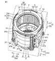
以下には、図面を参照して、この発明の実施形態について具体的に説明する。図1は、この発明の一実施形態に係る洗濯機1の内部構造を上方から見た斜視図である。   Embodiments of the present invention will be specifically described below with reference to the drawings. FIG. 1 is a perspective view of an internal structure of a washing machine 1 according to an embodiment of the present invention as viewed from above.

なお、洗濯機1の方向について言及する場合には、図1における洗濯機1の姿勢を基準とする。図1における上下方向は、洗濯機1の上下方向Z(縦方向)と一致する。上下方向Zのうち、上方を上方Z1と称し、下方を下方Z2と称する。図1における左右方向は、洗濯機1の左右方向Xと一致する。左右方向Xのうち、左方を左方X1と称し、右方を右方X2と称する。上下方向Zと左右方向Xとの両方に直交する方向は、洗濯機1の前後方向Yである。前後方向Yのうち、前方を前方Y1と称し、後方を後方Y2と称する。左右方向Xおよび前後方向Yは、水平方向H(横方向)に含まれる。   In addition, when mentioning the direction of the washing machine 1, the attitude | position of the washing machine 1 in FIG. 1 is made into a reference | standard. The vertical direction in FIG. 1 coincides with the vertical direction Z (longitudinal direction) of the washing machine 1. In the vertical direction Z, the upper part is referred to as an upper part Z1, and the lower part is referred to as a lower part Z2. The left-right direction in FIG. 1 coincides with the left-right direction X of the washing machine 1. Of the left and right directions X, the left side is referred to as the left side X1, and the right side is referred to as the right side X2. The direction orthogonal to both the vertical direction Z and the horizontal direction X is the front-rear direction Y of the washing machine 1. In the front-rear direction Y, the front is referred to as the front Y1, and the rear is referred to as the rear Y2. The left-right direction X and the front-rear direction Y are included in the horizontal direction H (lateral direction).

図1を参照して、洗濯機1は、筐体2と、外槽3と、洗濯槽5とを含む。
筐体2は、略直方体形状の中空体であり、外槽3および洗濯槽5は、筐体2内に収容される。
Referring to FIG. 1, washing machine 1 includes a housing 2, an outer tub 3, and a washing tub 5.
The housing 2 is a substantially rectangular parallelepiped hollow body, and the outer tub 3 and the washing tub 5 are accommodated in the housing 2.

外槽3は、ばねと減衰機構とを有する複数の吊棒(図示せず)を介して、筐体2によって支持される。外槽3は、上下方向Zに延びる軸線を有する円筒状に形成され、樹脂製である。円筒状の外槽3の周方向を周方向Sと称する。周方向Sのうち、上方Z1から見て時計回り側を時計回り側S1と称し、上方Z1から見て反時計回り側を反時計回り側S2と称する。外槽3の径方向を径方向Rと称する。径方向Rのうち、外槽3の軸線に近づく内側を径方向内側R1と称し、軸線から離れる外側を径方向外側R2と称する。   The outer tub 3 is supported by the housing 2 via a plurality of suspension bars (not shown) having a spring and a damping mechanism. The outer tub 3 is formed in a cylindrical shape having an axis extending in the vertical direction Z, and is made of resin. The circumferential direction of the cylindrical outer tub 3 is referred to as a circumferential direction S. Of the circumferential direction S, the clockwise side as viewed from above Z1 is referred to as the clockwise side S1, and the counterclockwise side as viewed from above Z1 is referred to as the counterclockwise side S2. The radial direction of the outer tub 3 is referred to as a radial direction R. Of the radial direction R, the inner side approaching the axis of the outer tub 3 is referred to as a radial inner side R1, and the outer side away from the axis is referred to as a radial outer side R2.

外槽3は、上下方向Zに延びる円筒状の側壁6と、水平方向Hに平坦に延びて側壁6の下端を塞ぐ円盤状の底壁7と、側壁6の上端部から周方向Sにおける全域に亘って径方向内側R1へ張り出した中空の環状壁8とを有する。側壁6の外周面6Aは、外槽3の外側面である。外槽3内には、底壁7側から水が溜められる。   The outer tub 3 includes a cylindrical side wall 6 extending in the vertical direction Z, a disk-shaped bottom wall 7 extending flat in the horizontal direction H and closing the lower end of the side wall 6, and the entire region in the circumferential direction S from the upper end of the side wall 6. And a hollow annular wall 8 projecting radially inward R1. An outer peripheral surface 6 </ b> A of the side wall 6 is an outer surface of the outer tub 3. In the outer tub 3, water is stored from the bottom wall 7 side.

外槽3の上端には、環状壁8の内周縁によって区画された円形状の開口9が形成される。開口9は、外槽3の内部を上方Z1へ露出させる。環状壁8は、複数(ここでは4つ)の突出部10を有する。複数の突出部10は、周方向Sに間隔を隔てて配置され、上方Z1から見て、環状壁8の外側周縁部から径方向外側R2へ略三角形状に張り出すように形成される。それぞれの突出部10は、平面視で略四角形状に形成された筐体2の四隅に1つずつ配置される。それぞれの突出部10は、中空体である。   A circular opening 9 defined by the inner peripheral edge of the annular wall 8 is formed at the upper end of the outer tub 3. The opening 9 exposes the inside of the outer tub 3 to the upper side Z1. The annular wall 8 has a plurality of (here, four) protrusions 10. The plurality of protrusions 10 are arranged at intervals in the circumferential direction S, and are formed so as to project in a substantially triangular shape from the outer peripheral edge of the annular wall 8 to the radially outer side R2 when viewed from above Z1. Each protrusion 10 is arranged one by one at the four corners of the housing 2 formed in a substantially quadrangular shape in plan view. Each protrusion 10 is a hollow body.

洗濯槽5は、上下方向Zに延びる軸線を有する円筒状に形成され、外槽3よりも一回り小さい。洗濯槽5には、洗濯物が収容される。洗濯槽5は、上下方向Zに延びる円筒状に形成された金属製の側壁20と、水平方向Hに平坦に延び側壁20の下端を塞ぐ円盤状に形成された樹脂製の底壁21と、洗濯槽5の上端に取り付けられる樹脂製のバランスリング22とを有する。側壁20および底壁21のそれぞれには、多数の貫通穴23が形成される。   The washing tub 5 is formed in a cylindrical shape having an axis extending in the vertical direction Z and is slightly smaller than the outer tub 3. The laundry is stored in the washing tub 5. The washing tub 5 has a metal side wall 20 formed in a cylindrical shape extending in the vertical direction Z, and a resin bottom wall 21 formed in a disk shape extending flat in the horizontal direction H and closing the lower end of the side wall 20; And a resin balance ring 22 attached to the upper end of the washing tub 5. A large number of through holes 23 are formed in each of the side wall 20 and the bottom wall 21.

バランスリング22は、液体が収容された内部空間を有する環状の中空体であって、側壁20の上端部に対して同軸状で取り付けられる。後述するように洗濯槽5が回転する際に、洗濯槽5の回転のバランスが、バランスリング22内での液体の移動によって維持される。洗濯槽5の上端には、バランスリング22の内周縁によって区画された円形状の開口24が形成される。開口24は、洗濯槽5の内部を上方Z1へ露出させる。   The balance ring 22 is an annular hollow body having an internal space in which a liquid is accommodated, and is attached coaxially to the upper end portion of the side wall 20. As will be described later, when the washing tub 5 rotates, the balance of rotation of the washing tub 5 is maintained by the movement of the liquid in the balance ring 22. A circular opening 24 defined by the inner peripheral edge of the balance ring 22 is formed at the upper end of the washing tub 5. The opening 24 exposes the inside of the washing tub 5 to the upper side Z1.

洗濯槽5は、外槽3内に収容され、外槽3とほぼ同軸状で配置される。そのため、洗濯槽5の周方向は、前述した周方向Sであり、洗濯槽5の径方向は、前述した径方向Rである。径方向内側R1は、洗濯槽5の中心の軸線に向かう方向であり、径方向外側R2は、洗濯槽5の軸線から離れて外周側の側壁20に向かう方向である。洗濯槽5の開口24は、外槽3の開口9に対して下方Z2から連通する。連通状態の開口9および24は、洗濯物の出入口25を構成する。洗濯機1の使用者は、洗濯物を、出入口25を介して洗濯槽5に対して上方Z1から出し入れする。外槽3内に収容された洗濯槽5では、底壁21が、外槽3の底壁7に対して隙間を隔てて上方Z1から対向する。   The washing tub 5 is accommodated in the outer tub 3 and is arranged substantially coaxially with the outer tub 3. Therefore, the circumferential direction of the washing tub 5 is the circumferential direction S described above, and the radial direction of the washing tub 5 is the radial direction R described above. The radially inner side R <b> 1 is a direction toward the central axis of the washing tub 5, and the radial outer side R <b> 2 is a direction away from the axis of the washing tub 5 toward the outer peripheral side wall 20. The opening 24 of the washing tub 5 communicates with the opening 9 of the outer tub 3 from below Z2. The communicating openings 9 and 24 constitute a laundry entrance 25. The user of the washing machine 1 puts the laundry in and out of the washing tub 5 through the entrance 25 from above Z1. In the washing tub 5 accommodated in the outer tub 3, the bottom wall 21 faces the bottom wall 7 of the outer tub 3 from above Z 1 with a gap.

外槽3に溜まった水は、洗濯槽5の側壁20および底壁21のそれぞれにおける貫通穴23を通ることによって、外槽3と洗濯槽5との間を行き来する。そのため、外槽3内の水位と洗濯槽5内の水位とは、ほぼ一致する。   The water accumulated in the outer tub 3 passes between the outer tub 3 and the washing tub 5 by passing through the through holes 23 in the side wall 20 and the bottom wall 21 of the washing tub 5. Therefore, the water level in the outer tub 3 and the water level in the washing tub 5 substantially coincide.

図2は、洗濯機1の内部構造の縦断面図である。詳しくは、図2は、洗濯機1の左右方向Xにおける略中央部を前後方向Yに沿って切断したときの断面を右方X2から見た図である。   FIG. 2 is a longitudinal sectional view of the internal structure of the washing machine 1. Specifically, FIG. 2 is a view of a cross section of the washing machine 1 as viewed from the right side X2 when a substantially central portion in the left-right direction X is cut along the front-rear direction Y.

図2を参照して、洗濯機1は、モータ30と、伝達軸31と、減速機構などで構成された伝達機構32と、分散手段29とを含む。   With reference to FIG. 2, the washing machine 1 includes a motor 30, a transmission shaft 31, a transmission mechanism 32 constituted by a speed reduction mechanism and the like, and a dispersion means 29.

モータ30は、電気駆動されることによってトルクを発生する。モータ30は、筐体2内において、外槽3の底壁7の下方Z2に配置される。モータ30は、トルクを出力する出力軸34を有する。出力軸34は、モータ30から上方Z1へ延びる。   The motor 30 generates torque by being electrically driven. The motor 30 is disposed in the lower portion Z <b> 2 of the bottom wall 7 of the outer tub 3 in the housing 2. The motor 30 has an output shaft 34 that outputs torque. The output shaft 34 extends upward from the motor 30 to Z1.

伝達軸31は、外槽3の底壁7の円中心部分を貫通して上方Z1へ延びる。伝達軸31は、出力軸34の上方Z1に同軸状で配置される。出力軸34と伝達軸31とは、伝達機構32を介して互いに連結される。   The transmission shaft 31 passes through the circular center portion of the bottom wall 7 of the outer tub 3 and extends upward Z1. The transmission shaft 31 is coaxially disposed above the output shaft 34 Z1. The output shaft 34 and the transmission shaft 31 are connected to each other via the transmission mechanism 32.

伝達軸31の上端部は、洗濯槽5の底壁21の円中心部分に連結される。モータ30が発生したトルクは、出力軸34および伝達機構32を経て伝達軸31に伝達される。これにより、洗濯槽5が、伝達軸31を回転中心として、伝達軸31とともに回転する。洗濯槽5の回転方向は、周方向Sと一致する。   An upper end portion of the transmission shaft 31 is connected to a circular center portion of the bottom wall 21 of the washing tub 5. Torque generated by the motor 30 is transmitted to the transmission shaft 31 via the output shaft 34 and the transmission mechanism 32. Thereby, the washing tub 5 rotates together with the transmission shaft 31 with the transmission shaft 31 as a rotation center. The rotation direction of the washing tub 5 coincides with the circumferential direction S.

分散手段29は、洗濯槽5の中心側と外周側とに水を分散させるためのものであり、変更手段としての制御部33を含む。制御部33は、たとえば、CPUやROMやRAMなどを含むマイコンとして構成され、筐体2(図1参照)内に配置される。制御部33は、図示しない信号回路によってモータ30に接続される。制御部33は、モータ30が発生するトルクを制御することで、洗濯槽5の回転速度を変更することができる。   The dispersing means 29 is for dispersing water on the center side and the outer peripheral side of the washing tub 5, and includes a control unit 33 as a changing means. The control part 33 is comprised as a microcomputer containing CPU, ROM, RAM etc., for example, and is arrange | positioned in the housing | casing 2 (refer FIG. 1). The control unit 33 is connected to the motor 30 by a signal circuit (not shown). The controller 33 can change the rotation speed of the washing tub 5 by controlling the torque generated by the motor 30.

外槽3に溜まった水に洗剤が溶けた状態で洗濯槽5が回転することにより、洗濯槽5内に収容された洗濯物の洗い運転が実行される。洗い運転後に、外槽3に給水された状態で洗濯槽5が回転することにより、洗濯槽5内に収容された洗濯物のすすぎ運転が実行される。外槽3の排水が行われた状態で洗濯槽5が高速回転することにより、洗濯槽5内に収容された洗濯物の脱水運転が実行される。   The washing tub 5 rotates in a state where the detergent is dissolved in the water stored in the outer tub 3, whereby the washing operation of the laundry stored in the washing tub 5 is executed. After the washing operation, the washing tub 5 rotates while being supplied to the outer tub 3, thereby rinsing the laundry stored in the washing tub 5. When the washing tub 5 rotates at a high speed while the outer tub 3 is drained, the dehydration operation of the laundry stored in the washing tub 5 is executed.

洗濯槽5の底壁21の下面21Aには、下方Z2に突出する複数の羽根35が一体的に設けられる。それぞれの羽根35は、周方向Sに薄く径方向Rに沿って直線状に延びる板状に形成され、底壁21の円中心を基準として放射状に配置される。これらの羽根35は、外槽3と非接触の状態で、底壁21と外槽3の底壁7との上下方向Zにおける隙間36に配置される。   A plurality of blades 35 projecting downward Z2 are integrally provided on the lower surface 21A of the bottom wall 21 of the washing tub 5. Each of the blades 35 is formed in a plate shape that is thin in the circumferential direction S and extends linearly along the radial direction R, and is arranged radially with respect to the circle center of the bottom wall 21. These blades 35 are arranged in a gap 36 in the vertical direction Z between the bottom wall 21 and the bottom wall 7 of the outer tub 3 in a non-contact state with the outer tub 3.

洗濯機1は、筐体2内に収容される水路4を含む。水路4は、樹脂製の細長いパイプ37を含む。パイプ37は、前述した突出部10(図1参照)と同数(ここでは4つ)となるように側壁6の外周面6Aに複数設けられる。パイプ37は、外槽3の側壁6の下端部から径方向外側R2へ向けて水平方向Hに延び出た下端部37Aと、下端部37Aから折れ曲がって外周面6Aに沿って上方Z1へ延びた途中部37Bと、途中部37Bから上方Xへ延びて突出部10に対して下方Z2から接続された上端部37C(図1参照)とを有する。途中部37Bは、上下方向Zに沿って直線状に延びる必要は無く、必要に応じて湾曲したり屈曲したりしながら上方Z1へ延びてもよい。   The washing machine 1 includes a water channel 4 accommodated in the housing 2. The water channel 4 includes an elongated pipe 37 made of resin. A plurality of pipes 37 are provided on the outer peripheral surface 6A of the side wall 6 so as to have the same number (here, four) as the protrusions 10 (see FIG. 1) described above. The pipe 37 extends from the lower end portion of the side wall 6 of the outer tub 3 toward the radially outer side R2 in the horizontal direction H, and bends from the lower end portion 37A and extends upward Z1 along the outer peripheral surface 6A. The intermediate portion 37B has an upper end portion 37C (see FIG. 1) that extends upward X from the intermediate portion 37B and is connected to the protruding portion 10 from the lower Z2. The middle portion 37B does not need to extend linearly along the up-down direction Z, and may extend upward Z1 while being bent or bent as necessary.

それぞれのパイプ37は、突出部10と同様に、筐体2の四隅に1つずつ配置される(図1参照)。それぞれのパイプ37は、下端部37Aと外槽3の側壁6との接続部分に受入口38を有し、パイプ37の内部空間39は、受入口38において外槽3の内部、詳しくは、前述した隙間36に連通する。   Each pipe 37 is arranged one by one at the four corners of the housing 2 in the same manner as the protruding portion 10 (see FIG. 1). Each pipe 37 has a receiving port 38 at a connection portion between the lower end portion 37A and the side wall 6 of the outer tub 3, and an internal space 39 of the pipe 37 is formed inside the outer tub 3 at the receiving port 38. The gap 36 is communicated.

水路4は、パイプ37に加えて、前述した外槽3の環状壁8も、水路4の構成部品として含む。環状壁8は、カバー40および底部41を含む。カバー40および底部41のそれぞれは、周方向Sに沿って延びる円環状に形成される。カバー40は、上下方向Zに薄い板状であり、径方向内側R1へ向かうにしたがって下方Z2へ向かうように水平方向Hに対して傾斜する。底部41は、上下方向Zに薄い板状であり、水平方向Hに沿って配置される。底部41は、外槽3の側壁6の上端部に一体化される。このように、外槽3の環状壁8を構成するカバー40および底部41が水路4の一部を兼ねるので、部品点数の削減を図れる。   The water channel 4 includes the annular wall 8 of the outer tub 3 described above as a component of the water channel 4 in addition to the pipe 37. The annular wall 8 includes a cover 40 and a bottom 41. Each of the cover 40 and the bottom 41 is formed in an annular shape extending along the circumferential direction S. The cover 40 has a thin plate shape in the vertical direction Z, and is inclined with respect to the horizontal direction H so as to be directed downward Z2 toward the radial inner side R1. The bottom 41 has a thin plate shape in the vertical direction Z and is disposed along the horizontal direction H. The bottom 41 is integrated with the upper end of the side wall 6 of the outer tub 3. Thus, since the cover 40 and the bottom 41 constituting the annular wall 8 of the outer tub 3 also serve as a part of the water channel 4, the number of parts can be reduced.

カバー40は、底部41に対して、同軸状で上方Z1から被せられる。カバー40と底部41との間には、内部空間42が形成される。内部空間42は、環状壁8の中空部分であり、周方向Sに沿って延びる環状に形成される。   The cover 40 is coaxially covered with respect to the bottom 41 from above Z1. An internal space 42 is formed between the cover 40 and the bottom 41. The internal space 42 is a hollow portion of the annular wall 8 and is formed in an annular shape extending along the circumferential direction S.

図3は、図2においてIIIで示した部分の拡大図である。図3では、紙面の右側が径方向内側R1であり、紙面の左側が径方向外側R2である。   FIG. 3 is an enlarged view of a portion indicated by III in FIG. In FIG. 3, the right side of the drawing is the radially inner side R1, and the left side of the drawing is the radially outer side R2.

図3を参照して、カバー40は、径方向内側R1の第1部分44と、第1部分44から連続して径方向外側R2へ延びる第2部分45とを含む。水平方向Hに対するカバー40の傾斜は、第1部分44と第2部分45との連結部40Aを境界として異なる。水平方向Hに対する第1部分44の傾斜は、水平方向Hに対する第2部分45の傾斜よりも急である。カバー40の径方向外側R2における端部には、下方Z2へ突出する外側リブ40Bが設けられる。底部41の径方向外側R2の端部には、上方Z1に突出して周方向Sに延びる円弧状に形成された外側リブ41Aが設けられる。   Referring to FIG. 3, the cover 40 includes a first portion 44 on the radially inner side R <b> 1 and a second portion 45 extending continuously from the first portion 44 to the radially outer side R <b> 2. The inclination of the cover 40 with respect to the horizontal direction H differs with the connecting portion 40A between the first portion 44 and the second portion 45 as a boundary. The inclination of the first portion 44 with respect to the horizontal direction H is steeper than the inclination of the second portion 45 with respect to the horizontal direction H. An outer rib 40B that protrudes downward Z2 is provided at the end of the cover 40 on the radially outer side R2. An outer rib 41A formed in an arc shape that protrudes upward Z1 and extends in the circumferential direction S is provided at the end of the bottom portion 41 on the radially outer side R2.

カバー40の外側リブ40Bは、底部41の外側リブ41Aに径方向外側R2から接する。カバー40では、第1部分44と第2部分45との連結部40Aが、底部41の径方向内側R1における端部41Bに最も接近し、上方Z1から非接触で対向する。第1部分44の径方向内側R1における端部44Aは、底部41の端部41Bよりも径方向内側R1かつ下方Z2に位置する。   The outer rib 40B of the cover 40 contacts the outer rib 41A of the bottom portion 41 from the radially outer side R2. In the cover 40, the connecting portion 40A between the first portion 44 and the second portion 45 is closest to the end portion 41B on the radially inner side R1 of the bottom portion 41 and faces the upper portion Z1 in a non-contact manner. The end portion 44A on the radially inner side R1 of the first portion 44 is located on the radially inner side R1 and below the lower side Z2 relative to the end portion 41B of the bottom portion 41.

環状壁8の内部空間42は、底部41の外側リブ41Aよりも径方向内側R1において、カバー40の第2部分45と底部41とによって上下方向Zから挟まれた第1空間46を含む。第1空間46は、周方向Sに延びる環状であり、カバー40の第2部分45の傾斜に伴って、径方向内側R1へ向かうにしたがって上下方向Zに狭くなる。   The inner space 42 of the annular wall 8 includes a first space 46 sandwiched from the vertical direction Z by the second portion 45 and the bottom portion 41 of the cover 40 on the radially inner side R1 of the outer rib 41A of the bottom portion 41. The first space 46 has an annular shape extending in the circumferential direction S, and becomes narrower in the vertical direction Z toward the radially inner side R <b> 1 as the second portion 45 of the cover 40 is inclined.

カバー40の連結部40Aおよび第1部分44と、底部41の径方向内側R1における端部41Bとの隙間は、吐出口43である。吐出口43は、周方向Sに沿って延びる環状のスリット状に形成される。つまり、吐出口43は、環状壁8の径方向内側R1の端部において、周方向Sの全域に亘って設けられる。吐出口43は、カバー40の第1部分44の傾斜に沿って、径方向内側R1かつ下方Z2を臨む。吐出口43は、内部空間42の第1空間46を周方向Sの全域に亘って径方向内側R1へ露出させる(図2参照)。   A gap between the connecting portion 40 </ b> A and the first portion 44 of the cover 40 and the end portion 41 </ b> B on the radially inner side R <b> 1 of the bottom portion 41 is a discharge port 43. The discharge port 43 is formed in an annular slit shape that extends along the circumferential direction S. That is, the discharge port 43 is provided over the entire region in the circumferential direction S at the end of the annular wall 8 on the radially inner side R1. The discharge port 43 faces the radially inner side R1 and the lower side Z2 along the inclination of the first portion 44 of the cover 40. The discharge port 43 exposes the first space 46 of the internal space 42 to the radially inner side R1 over the entire circumferential direction S (see FIG. 2).

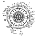
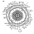
図4は、洗濯機1を上方Z1から見た図である。図5は、図4において外槽3からカバー40を取り外した図である。   FIG. 4 is a view of the washing machine 1 as viewed from above Z1. FIG. 5 is a view in which the cover 40 is removed from the outer tub 3 in FIG. 4.

図4を参照して、カバー40は、径方向外側R2へ略三角形状に張り出す突出部48を有する。底部41は、径方向外側R2へ略三角形状に張り出す突出部49を有する(図5参照)。突出部48および突出部49のそれぞれは、上下方向Zに薄い板状であって、前述した突出部10と同数(ここでは4つ)設けられる。4つの突出部48は、カバー40の外周部において、周方向Sに略等間隔で並ぶ。4つの突出部49は、底部41の外周部において、周方向Sに略等間隔で並ぶ。   Referring to FIG. 4, the cover 40 has a protruding portion 48 that protrudes in a substantially triangular shape toward the radially outer side R2. The bottom 41 has a protrusion 49 that protrudes in a substantially triangular shape toward the radially outer side R2 (see FIG. 5). Each of the protrusions 48 and the protrusions 49 has a thin plate shape in the vertical direction Z, and is provided in the same number (four in this case) as the protrusions 10 described above. The four protruding portions 48 are arranged at substantially equal intervals in the circumferential direction S on the outer peripheral portion of the cover 40. The four protruding portions 49 are arranged at substantially equal intervals in the circumferential direction S on the outer peripheral portion of the bottom portion 41.

図5を参照して、底部41には、外側リブ41Aの一部として径方向外側R2へ突出するリブ49Aが設けられる。リブ49Aは、それぞれの突出部49に設けられ、略三角形状の突出部49を径方向外側R2から縁取るように、上方Z1から見て略V字状に形成される。   Referring to FIG. 5, the bottom 41 is provided with a rib 49 </ b> A that protrudes radially outward R <b> 2 as a part of the outer rib 41 </ b> A. The ribs 49A are provided in the respective protrusions 49, and are formed in a substantially V shape when viewed from the upper side Z1 so as to border the substantially triangular protrusion 49 from the radially outer side R2.

図4を参照して、底部41に取り付けられたカバー40では、それぞれの突出部48が、底部41の突出部49に対して1つずつ上方Z1から重なる。重なった状態の突出部48および49は、それぞれの外縁部に取り付けられたねじ51によって一体化され、前述した突出部10を構成する。カバー40と底部41とは、周方向Sで突出部10とずれた位置に組み付けられたねじ52によっても、互いに連結される。   With reference to FIG. 4, in the cover 40 attached to the bottom 41, each protrusion 48 overlaps the protrusion 49 of the bottom 41 one by one from above Z <b> 1. The protruding portions 48 and 49 in an overlapped state are integrated by screws 51 attached to the respective outer edge portions to constitute the protruding portion 10 described above. The cover 40 and the bottom portion 41 are also connected to each other by a screw 52 that is assembled at a position shifted from the protruding portion 10 in the circumferential direction S.

環状壁8の内部空間42は、突出部10の中空部分を構成する第2空間55を含む。図5を参照して、突出部10の第2空間55は、突出部48および49によって上下方向Zから挟まれてリブ49Aによって径方向外側R2から塞がれた空間であり、第1空間46に径方向外側R2から連通する。   The internal space 42 of the annular wall 8 includes a second space 55 that constitutes a hollow portion of the protrusion 10. Referring to FIG. 5, the second space 55 of the protruding portion 10 is a space that is sandwiched from the vertical direction Z by the protruding portions 48 and 49 and is blocked from the radially outer side R2 by the rib 49A. Communicating from the radially outer side R2.

それぞれのパイプ37の内部空間39は、上端部37Cと突出部10との接続部分56において、突出部10の第2空間55に連通する。パイプ37の内部空間39は、第2空間55を介して第1空間46に連通する。   The internal space 39 of each pipe 37 communicates with the second space 55 of the protruding portion 10 at the connection portion 56 between the upper end portion 37C and the protruding portion 10. The internal space 39 of the pipe 37 communicates with the first space 46 through the second space 55.

図2を参照して、洗濯槽5がモータ30のトルクを受けて回転すると、洗濯槽5の底壁21の羽根35は、洗濯槽5と一体回転する。これにより、羽根35は、外槽3に溜まった水、詳しくは、洗濯槽5の底壁21と外槽3の底壁7との隙間36に存在する水を、それぞれのパイプ37の受入口38から内部空間39に送り込む。また、隙間36に存在する水は、羽根35の回転によって遠心力が生じて、パイプ37の受入口38から内部空間39に送り込まれる。内部空間39に送り込まれた水は、後続の水に押されることによってパイプ37内を上昇する。   Referring to FIG. 2, when the washing tub 5 receives the torque of the motor 30 and rotates, the blades 35 on the bottom wall 21 of the washing tub 5 rotate integrally with the washing tub 5. As a result, the blades 35 receive the water accumulated in the outer tub 3, specifically, the water existing in the gap 36 between the bottom wall 21 of the washing tub 5 and the bottom wall 7 of the outer tub 3. 38 is sent into the internal space 39. Further, the water present in the gap 36 generates centrifugal force due to the rotation of the blades 35 and is sent into the internal space 39 from the receiving port 38 of the pipe 37. The water fed into the internal space 39 rises in the pipe 37 by being pushed by the subsequent water.

図5を参照して、それぞれのパイプ37の上端部37Cまで上昇した水は、環状壁8の内部空間42の対応する第2空間55に流入する。それぞれの第2空間55に流入した水は、リブ49Aに導かれて、実線矢印で示すように、接続部分56から径方向内側R1へ向けて放射状に広がりながら第1空間46に流入する。   Referring to FIG. 5, the water that has risen to the upper end portion 37 </ b> C of each pipe 37 flows into the corresponding second space 55 of the internal space 42 of the annular wall 8. The water flowing into each second space 55 is guided to the rib 49A, and flows into the first space 46 while spreading radially from the connecting portion 56 toward the radially inner side R1, as indicated by solid arrows.

前述したように、第1空間46は、径方向内側R1へ向かうにしたがって上下方向Zに狭くなる(図3参照)。よって、第1空間46に流入した水は、第1空間46内において、周方向Sにおけるどこかの領域に偏ることなく、周方向Sに広がりながら径方向内側R1へ向かう。そのため、周方向Sの全体で見ると、それぞれのパイプ37から第2空間55を経て第1空間46に流入した水は、第1空間46において周方向Sの全域から径方向内側R1へ向かう。   As described above, the first space 46 becomes narrower in the up-down direction Z toward the radially inner side R1 (see FIG. 3). Therefore, the water that has flowed into the first space 46 is directed toward the radially inner side R <b> 1 while spreading in the circumferential direction S without being biased to any region in the circumferential direction S in the first space 46. Therefore, when viewed in the entire circumferential direction S, the water flowing into the first space 46 from the respective pipes 37 through the second space 55 travels from the entire region in the circumferential direction S toward the radially inner side R1 in the first space 46.

第1空間46において径方向内側R1へ向かう水の流れる先にある吐出口43は、前述したように、周方向Sの全域に亘って設けられる。よって、第1空間46において周方向Sの全域から径方向内側R1へ向かう水は、破線矢印で示すように、吐出口43の周方向Sの全域から吐出される。吐出口43から吐出された水は、図2の破線矢印で示すように、カバー40の第1部分44の傾斜に沿って、洗濯槽5内を、洗濯槽5の中心へ向けて斜め下方へ流れ落ちる。   In the first space 46, the discharge port 43 at the flow destination of water toward the radially inner side R1 is provided over the entire area in the circumferential direction S as described above. Accordingly, the water that travels from the entire area in the circumferential direction S toward the radially inner side R1 in the first space 46 is discharged from the entire area in the circumferential direction S of the discharge port 43, as indicated by the dashed arrow. The water discharged from the discharge port 43 is obliquely downward in the washing tub 5 toward the center of the washing tub 5 along the inclination of the first portion 44 of the cover 40 as shown by the broken line arrow in FIG. run down.

このように、水路4は、外槽3に溜まった水を汲み上げ、水路4の吐出口43は、水路4によって汲み上げられた水を洗濯槽5内に上方Z1から吐出する。洗濯槽5内の水は、洗濯槽5の貫通穴23を通ることによって洗濯槽5と外槽3との間で行き来する。   Thus, the water channel 4 pumps up the water accumulated in the outer tub 3, and the discharge port 43 of the water channel 4 discharges the water pumped up by the water channel 4 from the upper side Z <b> 1 into the washing tub 5. Water in the washing tub 5 passes between the washing tub 5 and the outer tub 3 by passing through the through holes 23 of the washing tub 5.

これにより、水が循環しながら洗濯に用いられるので、節水が可能になる。前述したように、吐出口43は、円筒状の洗濯槽5の周方向Sの全域に亘って設けられるので、洗濯槽5の周方向Sの全域から洗濯槽5内に水を吐出できる。そのため、洗濯槽5に収容された洗濯物に、洗濯槽5の周方向Sの全域から万遍なく水を振り掛けることができる。   Thereby, since water is used for washing while circulating, water saving becomes possible. As described above, the discharge ports 43 are provided over the entire area in the circumferential direction S of the cylindrical washing tub 5, so that water can be discharged into the washing tub 5 from the entire area in the circumferential direction S of the washing tub 5. Therefore, water can be uniformly sprinkled on the laundry accommodated in the washing tub 5 from the entire circumferential direction S of the washing tub 5.

また、洗濯槽5の周方向Sの全域に亘って設けられた吐出口43は、多量の水を吐出できる。これにより、洗濯物を洗う際、吐出口43から吐出された多量の水が洗濯槽5内を勢いよく落下するので、水の落下の勢いによって洗濯槽5内の洗剤を泡立てることができる。そのため、泡立った洗剤によって洗濯物を効果的に洗うことができる。また、吐出口43から吐出された多量の水が洗濯槽5内に勢いよく落下するので、洗濯物に作用する機械力を増大させることができ洗濯機の洗浄力を向上することができる。また、洗濯槽5内に上方Z1から吐出される多量の水によって、洗濯物を効率的にすすぐことができるので、すすぎ運転における時間短縮を図れる。   Moreover, the discharge port 43 provided over the whole circumferential direction S of the washing tub 5 can discharge a lot of water. Thereby, when washing the laundry, a large amount of water discharged from the discharge port 43 falls down in the washing tub 5 vigorously, so that the detergent in the washing tub 5 can be bubbled by the falling force of the water. Therefore, the laundry can be effectively washed with the foamed detergent. In addition, since a large amount of water discharged from the discharge port 43 falls into the washing tub 5 vigorously, the mechanical force acting on the laundry can be increased and the washing power of the washing machine can be improved. Moreover, since the laundry can be efficiently rinsed by the large amount of water discharged from the upper side Z1 into the washing tub 5, the time required for the rinsing operation can be shortened.

そして、以下に述べる構成によって、水路4によって汲み上げられた水を、吐出口43からの水を洗濯槽5の中心側(径方向内側R1)と外周側(径方向外側R2)に分散して吐出させることができる。たとえば、制御部33(図2参照)は、モータ30を制御して洗濯槽5の回転速度を変更することで、外槽3内の水に生じる遠心力を調節し、水路4によって汲み上げられる水の勢いを調節することができる。詳しくは、遠心力が大きければ、水路4によって汲み上げられる水の勢いは強く、遠心力が小さければ、水路4によって汲み上げられる水の勢いは弱い。これにより、勢いが強い水を吐出口43から洗濯槽5の中心側に吐出させたり、勢いが弱い水を洗濯槽5の外周側に吐出させたりすることできる。すなわち、分散手段29の制御部33は、水路4によって汲み上げられた水を、吐出口43からの水を洗濯槽5の中心側と外周側とに分散して吐出させる。これにより、吐出口43から洗濯槽5内の洗濯物に、周方向Sおよび径方向Rの両方における全範囲に亘って、一層万遍なく水を振り掛けることができる。これにより、一層効果的に洗濯物を洗ったりすすいだりすることができる。   And by the structure described below, the water pumped up by the water channel 4 disperses and discharges the water from the discharge port 43 to the center side (radially inner R1) and the outer peripheral side (radially outer R2) of the washing tub 5. Can be made. For example, the control unit 33 (see FIG. 2) controls the motor 30 to change the rotational speed of the washing tub 5, thereby adjusting the centrifugal force generated in the water in the outer tub 3, and the water pumped up by the water channel 4. The momentum can be adjusted. Specifically, if the centrifugal force is large, the momentum of the water pumped up by the water channel 4 is strong, and if the centrifugal force is small, the momentum of the water pumped up by the water channel 4 is weak. Thereby, water with strong momentum can be discharged from the outlet 43 to the center side of the washing tub 5, or water with weak momentum can be discharged to the outer peripheral side of the washing tub 5. That is, the control unit 33 of the dispersion unit 29 causes the water pumped up by the water channel 4 to be dispersed and discharged from the discharge port 43 to the center side and the outer peripheral side of the washing tub 5. Thereby, water can be sprinkled more uniformly over the entire range in both the circumferential direction S and the radial direction R from the discharge port 43 to the laundry in the washing tub 5. Thereby, it is possible to wash and rinse the laundry more effectively.

次に、本発明の第一変形例について説明する。
図6は、図5に本発明の第1変形例を適用した図である。図6において、上記に説明した部材と同様の部材には、同一の参照符号を付し、その説明を省略する。このことは、後述する図7〜図11においても同様である。
Next, a first modification of the present invention will be described.
FIG. 6 is a diagram in which the first modification of the present invention is applied to FIG. In FIG. 6, the same members as those described above are denoted by the same reference numerals, and the description thereof is omitted. The same applies to FIGS. 7 to 11 described later.

図6を参照して、第1変形例では、分散手段29は、水路4の一部である環状壁8の底部41に形成された一対の第1リブ61および一対の第2リブ62を含む。一対の第1リブ61および一対の第2リブ62は、水路4内に設けられる。一対の第1リブ61および一対の第2リブ62で構成された組は、それぞれの突出部49に対応して1組ずつ(ここでは合計4組)設けられる。それぞれの組において、一対の第2リブ62は、一対の第1リブ61よりも時計回り側S1に位置する。第1リブ61および第2リブ62のそれぞれは、底部41の上面から上方Z1に突出し、筋状に延びる。   Referring to FIG. 6, in the first modification, the dispersing means 29 includes a pair of first ribs 61 and a pair of second ribs 62 formed on the bottom 41 of the annular wall 8 that is a part of the water channel 4. . The pair of first ribs 61 and the pair of second ribs 62 are provided in the water channel 4. One set (here, a total of four sets) is provided for each pair of the pairs of the first ribs 61 and the pair of second ribs 62 corresponding to the protrusions 49. In each set, the pair of second ribs 62 are located on the clockwise side S <b> 1 with respect to the pair of first ribs 61. Each of the first rib 61 and the second rib 62 protrudes upward Z1 from the upper surface of the bottom portion 41 and extends in a streak shape.

一対の第1リブ61は、突出部49の径方向内側R1の端部49Bと底部41の径方向内側R1の端部41Bとの間で径方向Rにほぼ沿って延びる。一対の第2リブ62は、突出部49の径方向内側R1の端部49Bから底部41の径方向内側R1の端部41Bに向かうにしたがって時計回り側S1に向かうように延びる。   The pair of first ribs 61 extend substantially along the radial direction R between the end portion 49 </ b> B on the radially inner side R <b> 1 of the protruding portion 49 and the end portion 41 </ b> B on the radially inner side R <b> 1 of the bottom portion 41. The pair of second ribs 62 extends from the end portion 49B on the radially inner side R1 of the protruding portion 49 toward the end portion 41B on the radially inner side R1 of the bottom portion 41 toward the clockwise side S1.

一対の第1リブ61のうち、反時計回り側S2の第1リブ61の径方向外側R2の端部は、突出部49を縁取るリブ49Aにおける反時計回り側S2の端部に連結される。一対の第2リブ62のうち、時計回り側S1の第2リブ62の径方向外側R2の端部は、リブ49Aにおける時計回り側S1の端部に連結される。この第2リブ62において、時計回り側S1の部分62Aは、径方向外側R2へ凸湾曲して形成される。   Of the pair of first ribs 61, the end portion on the radially outer side R2 of the first rib 61 on the counterclockwise side S2 is connected to the end portion on the counterclockwise side S2 of the rib 49A that borders the protruding portion 49. . Of the pair of second ribs 62, the end portion on the radially outer side R2 of the second rib 62 on the clockwise side S1 is connected to the end portion on the clockwise side S1 of the rib 49A. In the second rib 62, the portion 62A on the clockwise side S1 is formed to be convexly curved outward in the radial direction R2.

一対の第1リブ61のうち時計回り側S1の第1リブ61の径方向外側R2の端部と、一対の第2リブ62のうち反時計回り側S2の第2リブ62の径方向外側R2の端部とは、接続部分56よりも径方向内側R1において連結される。   Of the pair of first ribs 61, the radially outer end R <b> 2 of the first rib 61 on the clockwise side S <b> 1 and the radially outer side R <b> 2 of the second rib 62 on the counterclockwise side S <b> 2 of the pair of second ribs 62. Are connected to the end portion R1 on the radially inner side R1 from the connecting portion 56.

第1変形例では、第1空間46は、周方向Sにおいて複数(ここでは4つ)に分けられ、それぞれの第1空間46は、一対の第1リブ61によって周方向Sから挟まれた空間46Aと、一対の第2リブ62によって周方向Sから挟まれた空間46Bとを含む。   In the first modification, the first space 46 is divided into a plurality (here, four) in the circumferential direction S, and each first space 46 is a space sandwiched from the circumferential direction S by the pair of first ribs 61. 46 </ b> A and a space 46 </ b> B sandwiched from the circumferential direction S by the pair of second ribs 62.

それぞれの第1空間46において、空間46Aは、第2空間55から径方向Rにほぼ沿って径方向内側R1に延び、空間46Bは、第2空間55から径方向内側R1に向かうにしたがって時計回り側S1に向かうように延びる。そのため、それぞれの第1空間46と、第1空間46に径方向外側R2から連通する第2空間55とのまとまりは、上方Z1から見て、第2空間55から径方向内側R1へ向けて二股に分かれた略V字状をなす。空間46Aにおいて第2空間55から吐出口43までの距離は、空間46Bにおいて第2空間55から吐出口43までの距離よりも短い。   In each first space 46, the space 46A extends from the second space 55 to the radially inner side R1 substantially along the radial direction R, and the space 46B rotates clockwise from the second space 55 toward the radially inner side R1. Extends toward the side S1. Therefore, the unit of each first space 46 and the second space 55 communicating with the first space 46 from the radially outer side R2 is bifurcated from the second space 55 toward the radially inner side R1 when viewed from above Z1. It has an approximately V-shape divided into two. The distance from the second space 55 to the discharge port 43 in the space 46A is shorter than the distance from the second space 55 to the discharge port 43 in the space 46B.

洗濯槽5の回転によって水路4に送り込まれてそれぞれのパイプ37の上端部37Cまで上昇した水は、外槽3の環状壁8の突出部10の第2空間55に流入する。それぞれの第2空間55に流入した水は、実線矢印で示すように、第1リブ61および第2リブ62によって分岐されて第1空間46の空間46Aおよび空間46Bのそれぞれに流入する。   The water sent to the water channel 4 by the rotation of the washing tub 5 and rising to the upper end portion 37 </ b> C of each pipe 37 flows into the second space 55 of the protruding portion 10 of the annular wall 8 of the outer tub 3. The water flowing into each second space 55 is branched by the first rib 61 and the second rib 62 and flows into the space 46A and the space 46B of the first space 46, as indicated by solid arrows.

空間46Aに流入した水が吐出口43に到達するまでに移動する距離は、比較的短い。よって、点線矢印で示すように、空間46A内を移動した水は、勢いをほとんど失うことなく吐出口43から吐出されて洗濯槽5の中心側の洗濯物に振り掛けられる。   The distance that the water flowing into the space 46A moves to reach the discharge port 43 is relatively short. Therefore, as shown by the dotted arrow, the water that has moved in the space 46 </ b> A is discharged from the discharge port 43 and is sprinkled on the laundry on the center side of the washing tub 5 with almost no loss of momentum.

空間46Bに流入した水が吐出口43に到達するまでに移動する距離は、比較的長い。よって、1点鎖線矢印で示すように、空間46B内を移動した水は、勢いを失いながら吐出口43から吐出されるので、洗濯槽5の中心側まで届かず、時計回り側S1に流れながら、洗濯槽5の外周側の洗濯物に振り掛けられる。   The distance that the water flowing into the space 46B moves to reach the discharge port 43 is relatively long. Therefore, as indicated by the one-dot chain line arrow, the water that has moved in the space 46B is discharged from the discharge port 43 while losing momentum, so that it does not reach the center of the washing tub 5 and flows to the clockwise side S1. Then, it is sprinkled on the laundry on the outer peripheral side of the washing tub 5.

このように、水路4内に設けられた複数の第1リブ61および複数の第2リブ62によって、吐出口43から吐出される水が洗濯槽5の中心側と外周側に振り分けられることができる。これにより、吐出口43から洗濯槽5内の洗濯物に一層万遍なく水を振り掛けることができる。これにより、一層効果的に洗濯物を洗ったりすすいだりすることができる。   Thus, the water discharged from the discharge port 43 can be distributed to the center side and the outer peripheral side of the washing tub 5 by the plurality of first ribs 61 and the plurality of second ribs 62 provided in the water channel 4. . Thereby, water can be sprinkled even more uniformly on the laundry in the washing tub 5 from the discharge port 43. Thereby, it is possible to wash and rinse the laundry more effectively.

なお、以上の説明では、一対の第2リブ62は、一対の第1リブ61よりも時計回り側S1に位置したが、逆に、一対の第2リブ62が一対の第1リブ61よりも反時計回り側S2に位置してもよい。   In the above description, the pair of second ribs 62 is positioned on the clockwise side S1 with respect to the pair of first ribs 61, but conversely, the pair of second ribs 62 is more than the pair of first ribs 61. It may be located on the counterclockwise side S2.

また、一対の第1リブ61および一対の第2リブ62が延びる方向を調節することで、吐出口43から吐出される水の向きを自由に調節することができる。   In addition, by adjusting the direction in which the pair of first ribs 61 and the pair of second ribs 62 extend, the direction of water discharged from the discharge port 43 can be freely adjusted.

次に、本発明の第2変形例について説明する。
図7は、図3に本発明の第2変形例を適用した図である。
Next, a second modification of the present invention will be described.
FIG. 7 is a diagram in which the second modification of the present invention is applied to FIG.

図7を参照して、第2変形例のカバー40は、第1部分44を有しない。第2変形例では、カバー40の第2部分45の径方向内側R1の端部45Aは、底部41の径方向内側R1の端部41Bよりも径方向外側R2に位置する。第2変形例のカバー40には、ゴムなどの弾性変形可能な部材で構成されたパッキン63が設けられる。パッキン63は、カバー40、つまり水路4とは別体であり、上方Z1から見て円環状である。   With reference to FIG. 7, the cover 40 of the second modified example does not have the first portion 44. In the second modification, the end portion 45A on the radially inner side R1 of the second portion 45 of the cover 40 is located on the radially outer side R2 relative to the end portion 41B on the radially inner side R1 of the bottom portion 41. The cover 40 of the second modification is provided with a packing 63 made of an elastically deformable member such as rubber. The packing 63 is a separate body from the cover 40, that is, the water channel 4, and has an annular shape when viewed from above Z1.

パッキン63は、径方向内側R1へ向かうにしたがって下方Z2へ向かうように水平方向Hに対して傾斜する。カバー40の底部41の径方向内側R1における端部41Bよりも径方向外側R2では、水平方向Hに対するパッキン63の傾斜は、水平方向Hに対する第2部分45の傾斜と一致する。パッキン63では、底部41の端部41Bよりも径方向内側R1の部分63Aの水平方向Hに対する傾斜が、水平方向Hに対する第2部分45の傾斜よりも急である。   The packing 63 is inclined with respect to the horizontal direction H so as to be directed downward Z2 toward the radially inner side R1. The inclination of the packing 63 with respect to the horizontal direction H coincides with the inclination of the second portion 45 with respect to the horizontal direction H on the radially outer side R2 of the end portion 41B on the radially inner side R1 of the bottom 41 of the cover 40. In the packing 63, the inclination of the portion 63 </ b> A on the radially inner side R <b> 1 from the end portion 41 </ b> B of the bottom 41 with respect to the horizontal direction H is steeper than the inclination of the second portion 45 with respect to the horizontal direction H.

パッキン63は、カバー40の第2部分45に対して上方Z1から取り付けられる。パッキン63は、径方向外側R2の端部において第2部分45の端部45Aに接着される。第2変形例では、パッキン63において径方向内側R1の部分63Aと、底部41の径方向内側R1における端部41Bとの隙間が、吐出口43である。パッキン63は、上方Z1から吐出口43の一部を縁取る。パッキン63の径方向内側R1の端部63Bは、底部41よりも下方Z2および径方向内側R1に位置する。   The packing 63 is attached to the second portion 45 of the cover 40 from above Z1. The packing 63 is bonded to the end 45A of the second portion 45 at the end of the radially outer side R2. In the second modified example, a gap between the portion 63 </ b> A on the radially inner side R <b> 1 and the end portion 41 </ b> B on the radially inner side R <b> 1 of the bottom portion 41 is the discharge port 43. The packing 63 borders a part of the discharge port 43 from the upper side Z1. An end portion 63B of the packing 63 on the radially inner side R1 is located below the bottom portion 41 in the lower Z2 and the radially inner side R1.

パッキン63を設ける構成であれば、ごみなどによって吐出口43が詰まった場合には、水路4を分解しなくても、図7に二点鎖線で示すように、パッキン63を上方Z1へ曲げて吐出口43を広げることによって、容易に吐出口43を掃除できる。   In the configuration in which the packing 63 is provided, when the discharge port 43 is clogged with dust or the like, the packing 63 is bent upward Z1 as shown by a two-dot chain line in FIG. 7 without disassembling the water channel 4. By widening the discharge port 43, the discharge port 43 can be easily cleaned.

次に、本発明の第3変形例について説明する。
図8は、図3に本発明の第3変形例を適用した図である。
Next, a third modification of the present invention will be described.
FIG. 8 is a diagram in which the third modification of the present invention is applied to FIG.

図8を参照して、第3変形例が第2変形例と異なる点は、第2変形例のパッキン63(図7参照)の代わりに、パッキン64が設けられる点である。
パッキン64は、パッキン63と同様に、カバー40とは別体であり、上方Z1から見て円環状である。パッキン64は、径方向内側R1へ向かうにしたがって下方Z2へ向かうように水平方向Hに対して傾斜する。径方向Rにおけるパッキン64の途中部分は、下方Z2へ屈曲した段差65を有する。段差65は、径方向内側R1から第2部分45の径方向内側R1の端部に接する。パッキン64において、段差65よりも径方向内側R1の部分を第1部分66とし、段差65よりも径方向外側R2の部分を第2部分67とする。
Referring to FIG. 8, the third modification differs from the second modification in that packing 64 is provided instead of packing 63 (see FIG. 7) of the second modification.
Like the packing 63, the packing 64 is a separate body from the cover 40, and has an annular shape when viewed from above Z1. The packing 64 is inclined with respect to the horizontal direction H so as to be directed downward Z2 toward the radially inner side R1. A middle portion of the packing 64 in the radial direction R has a step 65 that is bent downward Z2. The step 65 is in contact with the end of the second portion 45 from the radially inner side R1 to the radially inner side R1. In the packing 64, a portion on the radially inner side R <b> 1 from the step 65 is referred to as a first portion 66, and a portion on the radially outer side R <b> 2 from the step 65 is referred to as a second portion 67.

第1部分66では、底部41の径方向内側R1の端部41Bよりも径方向外側R2の外側部分66Aの水平方向Hに対する傾斜が、水平方向Hに対する第2部分45の傾斜と一致する。第1部分66では、底部41の径方向内側R1の端部41Bよりも径方向内側R1の内側部分66Bの水平方向Hに対する傾斜が、水平方向Hに対する第2部分45の傾斜よりも急である。第2部分67の傾斜は、水平方向Hに対する第2部分45の傾斜と一致する。   In the first portion 66, the inclination of the outer portion 66 </ b> A on the radially outer side R <b> 2 with respect to the horizontal direction H with respect to the end portion 41 </ b> B on the radially inner side R <b> 1 of the bottom 41 coincides with the inclination of the second portion 45 with respect to the horizontal direction H. In the first portion 66, the inclination of the inner portion 66 </ b> B on the radially inner side R <b> 1 with respect to the horizontal direction H is steeper than the inclination of the second portion 45 with respect to the horizontal direction H than the end portion 41 </ b> B of the radially inner side R <b> 1 of the bottom portion 41. . The inclination of the second portion 67 coincides with the inclination of the second portion 45 with respect to the horizontal direction H.

パッキン64は、カバー40の第2部分45に対して上方Z1から取り付けられる。パッキン64は、段差65と第2部分67とにおいてカバー40に接着される。第3変形例では、パッキン64の第1部分66の内側部分66Bと、底部41の径方向内側R1における端部41Bとの隙間が、吐出口43である。パッキン64は、上方Z1から吐出口43の一部を縁取る。第1部分66の内側部分66Bの径方向内側R1の端部66Cは、底部41よりも下方Z2かつ径方向内側R1に位置する。   The packing 64 is attached to the second portion 45 of the cover 40 from above Z1. The packing 64 is bonded to the cover 40 at the step 65 and the second portion 67. In the third modified example, the gap between the inner portion 66B of the first portion 66 of the packing 64 and the end portion 41B on the radially inner side R1 of the bottom portion 41 is the discharge port 43. The packing 64 borders a part of the discharge port 43 from the upper side Z1. An end portion 66C of the inner side portion 66B of the first portion 66 on the radially inner side R1 is positioned below the bottom portion Z2 and on the radially inner side R1.

第3変形例の場合においても、ごみなどによって吐出口43が詰まった場合には、水路4を分解しなくても、図8に二点鎖線で示すように、パッキン64の第1部分66全体を上方Z1へ曲げて吐出口43を広げることによって、容易に吐出口43を掃除できる。   Even in the case of the third modification, when the discharge port 43 is clogged with dust or the like, the entire first portion 66 of the packing 64 can be obtained as shown by a two-dot chain line in FIG. Is bent upward Z1 to widen the discharge port 43, so that the discharge port 43 can be easily cleaned.

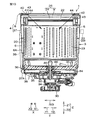
次に、本発明の第4変形例について説明する。
図9は、図2に本発明の第4変形例を適用した図である。
Next, a fourth modification of the present invention will be described.
FIG. 9 is a diagram in which the fourth modification of the present invention is applied to FIG.

図9を参照して、筐体2は、その上端部に、扉71と、上面板72とを含む。筐体2の上面には、開口74が形成される。開口74の下方Z2に出入口25が位置する。扉71は、本体70の開口74を上方Z1から塞ぐ。上面板72は、筐体2の上端部において開口74の後方Y2の部分に固定され、扉71の後端を支持する。   Referring to FIG. 9, the housing 2 includes a door 71 and an upper surface plate 72 at an upper end portion thereof. An opening 74 is formed on the upper surface of the housing 2. The entrance / exit 25 is located below the opening 74 at Z2. The door 71 closes the opening 74 of the main body 70 from above Z1. The upper surface plate 72 is fixed to the rear Y2 portion of the opening 74 at the upper end portion of the housing 2 and supports the rear end of the door 71.

洗濯機1の使用者は、洗濯機1の前方Y1から扉71を開くことができる。洗濯機1の使用者は、扉71を開いた状態で、出入口25を介して洗濯槽5に対して上方Z1から洗濯物を出し入れできる。扉71は、透明または半透明なので、使用者は、閉じた扉71越しに、洗濯槽5内の様子を目視で確認できる。   The user of the washing machine 1 can open the door 71 from the front Y1 of the washing machine 1. The user of the washing machine 1 can take in and out the laundry from the upper side Z1 with respect to the washing tub 5 through the entrance 25 with the door 71 opened. Since the door 71 is transparent or translucent, the user can visually confirm the state in the washing tub 5 through the closed door 71.

外槽3の側壁6は、半透明の樹脂製である。外槽3全体が半透明であってもよい。外槽3の底壁7には、外槽3内の水を排出するための図示しない排水口が形成される。排水口には、洗濯機1の機外に水を排出する排水路76が接続される。排水路76には、洗濯機1の機外に排出される水の汚れ度合を検知する汚れセンサ77が設けられる。汚れセンサ77として、公知の構成が用いられる。汚れセンサ77は、制御部33に対して電気的に接続される。汚れセンサ77による検知結果は、制御部33に入力される。   The side wall 6 of the outer tub 3 is made of a translucent resin. The entire outer tub 3 may be translucent. On the bottom wall 7 of the outer tub 3, a drain port (not shown) for discharging the water in the outer tub 3 is formed. A drainage channel 76 for discharging water to the outside of the washing machine 1 is connected to the drainage port. The drainage channel 76 is provided with a dirt sensor 77 that detects the degree of dirt of water discharged outside the washing machine 1. A known configuration is used as the dirt sensor 77. The dirt sensor 77 is electrically connected to the control unit 33. The detection result by the dirt sensor 77 is input to the control unit 33.

洗濯機1は、光源81を含む。光源81は、たとえば1つまたは複数のLEDから構成され、様々な色の光を発する。光源81は、制御部33に電気的に接続される。制御部33は、光源81の発光パターンを制御できる。   The washing machine 1 includes a light source 81. The light source 81 is composed of, for example, one or a plurality of LEDs and emits light of various colors. The light source 81 is electrically connected to the control unit 33. The control unit 33 can control the light emission pattern of the light source 81.

光源81は、たとえば、外槽3の側壁6の外周面6Aに後方Y2から取り付けられる。光源81が発する光は、洗濯槽5内の水に後方Y2から照射される。詳しくは、光源81が発する光は、半透明の外槽3の側壁6を透過して、洗濯槽5の側壁20の貫通穴23を通って洗濯槽5内の水に後方Y2から照射される。   The light source 81 is attached to the outer peripheral surface 6A of the side wall 6 of the outer tub 3 from the rear Y2, for example. The light emitted from the light source 81 is applied to the water in the washing tub 5 from the rear Y2. Specifically, the light emitted from the light source 81 passes through the side wall 6 of the translucent outer tub 3 and is irradiated from the rear Y2 to the water in the washing tub 5 through the through hole 23 of the side wall 20 of the washing tub 5. .

光源81の代わりに、別の光源82が設けられてもよい。光源82は、たとえば1つまたは複数のLEDから構成され、様々な色の光を発する。光源82は、制御部33に電気的に接続される。制御部33は、光源82の発光パターンを制御できる。光源82は、たとえば、上面板72の下面に下方Z2から取り付けられる。光源82が発する光は、洗濯槽5内の水または吐出口43から洗濯槽5内に吐出される水に上方Z1から照射される。   Instead of the light source 81, another light source 82 may be provided. The light source 82 includes, for example, one or a plurality of LEDs, and emits light of various colors. The light source 82 is electrically connected to the control unit 33. The control unit 33 can control the light emission pattern of the light source 82. The light source 82 is attached to the lower surface of the upper surface plate 72 from below Z2, for example. The light emitted from the light source 82 is irradiated from above the Z <b> 1 to water in the washing tub 5 or water discharged from the discharge port 43 into the washing tub 5.

光源81の代わりに、別の光源83が設けられてもよい。光源83は、複数設けられる。各光源83は、たとえば1つまたは複数のLEDから構成され、様々な色の光を発する。光源83は、制御部33に電気的に接続される。制御部33は、光源83の発光パターンを制御できる。   Instead of the light source 81, another light source 83 may be provided. A plurality of light sources 83 are provided. Each light source 83 is composed of, for example, one or a plurality of LEDs, and emits light of various colors. The light source 83 is electrically connected to the control unit 33. The control unit 33 can control the light emission pattern of the light source 83.

光源83が設けられる場合、外槽3は、上方Z1から見て円環状の支持部材73を含む。支持部材73は、環状壁8のカバー40に上方Z1から取り付けられる。複数の光源83は、たとえば、支持部材73の上面に上方Z1から取り付けられ、周方向Sに沿って並んで配置される。複数の光源83は、支持部材73の下面に下方Z2から取り付けられてもよい。光源83が発する光は、洗濯槽5内の水または吐出口43から洗濯槽5内に吐出される水に上方Z1から照射される。   When the light source 83 is provided, the outer tub 3 includes an annular support member 73 as viewed from above Z1. The support member 73 is attached to the cover 40 of the annular wall 8 from above Z1. The plurality of light sources 83 are, for example, attached to the upper surface of the support member 73 from above Z1 and arranged side by side along the circumferential direction S. The plurality of light sources 83 may be attached to the lower surface of the support member 73 from below Z2. The light emitted from the light source 83 is applied to the water in the washing tub 5 or the water discharged from the discharge port 43 into the washing tub 5 from above Z1.

これらの光源81、82および83は、単独で設けられてもよいし、組み合わさって設けられてもよい。洗濯槽5内の水または吐出口43から洗濯槽5に吐出される水は、以上の光源81や82や83から照射された光の色を帯びる。   These light sources 81, 82, and 83 may be provided alone or in combination. The water in the washing tub 5 or the water discharged from the outlet 43 to the washing tub 5 is colored with the light emitted from the light sources 81, 82, and 83.

洗濯機1の運転状態、すなわち洗濯物の洗浄およびすすぎの状態や、洗濯物の洗浄およびすすぎが終了するまでの時間などに応じて、光源81、82または83を点灯させたり、光源81、82または83が発する光の色を変化させたりする。これにより、洗濯機1の運転状態を使用者に視覚的に伝えることができる。   Depending on the operating state of the washing machine 1, that is, the washing and rinsing state of the laundry, the time until the washing and rinsing of the laundry are completed, the light source 81, 82 or 83 is turned on, or the light sources 81 and 82 are turned on. Or the color of the light emitted by 83 is changed. Thereby, the driving | running state of the washing machine 1 can be visually conveyed to a user.

すすぎ運転時に汚れセンサ77が検知する水の汚れ度合に応じて、光源81、82または83が発する光の色を変化させてもよい。たとえば、排水の汚れ度合が比較的高い場合には、各光源81、82または83が赤色の光を発し、排水の汚れ度合が低減されると当該光の色が赤から黄に変化する。さらに排水の汚れ度合が低減されると当該光の色が黄から青に変化する。そのため、洗濯物のすすぎの状態を洗濯機1の使用者に視覚的に伝えることができる。   The color of light emitted from the light source 81, 82 or 83 may be changed according to the degree of water contamination detected by the contamination sensor 77 during the rinsing operation. For example, when the degree of contamination of drainage is relatively high, each light source 81, 82 or 83 emits red light, and when the degree of contamination of drainage is reduced, the color of the light changes from red to yellow. Further, when the degree of contamination of the drainage is reduced, the color of the light changes from yellow to blue. Therefore, the state of rinsing the laundry can be visually transmitted to the user of the washing machine 1.

次に本発明の第5変形例について説明する。
図10は、図2に本発明の第5変形例を適用した図である。
Next, a fifth modification of the present invention will be described.
FIG. 10 is a diagram in which the fifth modification of the present invention is applied to FIG.

図10を参照して、洗濯機1は、洗濯槽5とは別体の揚水翼84を含む。揚水翼84は、洗濯槽5に対して周方向Sに相対回転可能である。第5変形例では、本実施形態とは異なり、洗濯槽5に複数の羽根35が形成されない。揚水翼84は、上方Z1から見て円形状であり、前述した複数の羽根35は、揚水翼84の上面に形成される。揚水翼84は、隙間36に配置される。   Referring to FIG. 10, washing machine 1 includes pumping blades 84 that are separate from washing tub 5. The pumping blade 84 can rotate relative to the washing tub 5 in the circumferential direction S. In the fifth modification, unlike the present embodiment, the plurality of blades 35 are not formed in the washing tub 5. The pumping blade 84 has a circular shape when viewed from above Z <b> 1, and the plurality of blades 35 described above are formed on the upper surface of the pumping blade 84. The pumping blade 84 is disposed in the gap 36.

第5変形例の洗濯機1は、本実施形態の伝達軸31に代えて、第1伝達軸85および第2伝達軸86を含む。第1伝達軸85は、上方Z1へ延びる。第2伝達軸86は、上方Z1へ延びる筒状であり、第1伝達軸85を収容する。第1伝達軸85と第2伝達軸86とは、互いに非接触の状態で、同軸状で配置される。   The washing machine 1 of the fifth modification includes a first transmission shaft 85 and a second transmission shaft 86 instead of the transmission shaft 31 of the present embodiment. The first transmission shaft 85 extends upward Z1. The second transmission shaft 86 has a cylindrical shape extending upward Z <b> 1 and accommodates the first transmission shaft 85. The first transmission shaft 85 and the second transmission shaft 86 are arranged coaxially in a non-contact state.

第1伝達軸85および第2伝達軸86は、出力軸34の上方Z1に出力軸34と同軸状で配置される。出力軸34と第1伝達軸85とは、伝達機構32を介して互いに連結される。出力軸34と第2伝達軸86とは、伝達機構32を介して互いに連結される。   The first transmission shaft 85 and the second transmission shaft 86 are arranged coaxially with the output shaft 34 above the output shaft 34 in Z1. The output shaft 34 and the first transmission shaft 85 are connected to each other via the transmission mechanism 32. The output shaft 34 and the second transmission shaft 86 are connected to each other via the transmission mechanism 32.

第1伝達軸85は、外槽3の底壁7の円中心部分を貫通して上方Z1へ延びる。第1伝達軸85の上端部は、洗濯槽5の底壁21の円中心部分に連結される。第2伝達軸86は、底壁21と外槽3の底壁7との上下方向Zにおける隙間36まで延びる。第2伝達軸86の上端部は、揚水翼84の円中心部分に連結される。   The first transmission shaft 85 extends upward Z1 through the center portion of the bottom wall 7 of the outer tub 3. An upper end portion of the first transmission shaft 85 is connected to a circular center portion of the bottom wall 21 of the washing tub 5. The second transmission shaft 86 extends to the gap 36 in the vertical direction Z between the bottom wall 21 and the bottom wall 7 of the outer tub 3. The upper end portion of the second transmission shaft 86 is connected to the circular center portion of the pumping blade 84.

モータ30が発生したトルクは、出力軸34および伝達機構32を経て、第1伝達軸85および第2伝達軸86のそれぞれに伝達される。洗濯槽5は、第1伝達軸85を回転中心として、第1伝達軸85とともに回転する。揚水翼84は、第2伝達軸86を回転中心として、第2伝達軸86とともに回転する。よって、第5変形例の洗濯機1では、揚水翼84の複数の羽根35を、洗濯槽5とは別に単独で回転させることができる。   Torque generated by the motor 30 is transmitted to each of the first transmission shaft 85 and the second transmission shaft 86 via the output shaft 34 and the transmission mechanism 32. The washing tub 5 rotates with the first transmission shaft 85 about the first transmission shaft 85 as a rotation center. The pumping blade 84 rotates with the second transmission shaft 86 around the second transmission shaft 86 as a rotation center. Therefore, in the washing machine 1 of the fifth modified example, the plurality of blades 35 of the pumping blade 84 can be rotated independently of the washing tub 5.

この構成では、揚水翼84だけを回転させることによって、モータ30の負荷が低減される。これにより、モータ30の温度上昇を防止できる。もちろん、揚水翼84とともに洗濯槽5も回転してもよい。そうすれば、洗濯槽5内での洗濯物の位置が入れ替わるため、洗濯物に万遍なく水を振り掛けることができる。この場合、洗濯槽5の回転方向と揚水翼84の回転方向とは、逆であってもよい。   In this configuration, the load on the motor 30 is reduced by rotating only the pumping blade 84. Thereby, the temperature rise of the motor 30 can be prevented. Of course, the washing tub 5 may also rotate with the pumping blade 84. If it does so, since the position of the laundry in the washing tub 5 will be switched, water can be sprinkled all over the laundry. In this case, the rotation direction of the washing tub 5 and the rotation direction of the pumping wing 84 may be reversed.

次に本発明の第6変形例について説明する。
図11は、図5に本発明の第6変形例を適用した図である。
Next, a sixth modification of the present invention will be described.
FIG. 11 is a diagram in which the sixth modification of the present invention is applied to FIG.

図11を参照して、第6変形例では、水路4の一部である環状壁8の底部41は、リブ87を含む。リブ87は、それぞれの突出部49に1つずつ設けられる。   Referring to FIG. 11, in the sixth modified example, the bottom 41 of the annular wall 8 that is a part of the water channel 4 includes a rib 87. One rib 87 is provided for each protrusion 49.

リブ87は、底部41の径方向外側R2の端部から径方向内側R1に向かうにしたがって時計回り側S1に向かうように直線的に延びる。リブ87の径方向外側R2の端部は、接続部分56よりも反時計回り側S2において突出部49のリブ49Aに連結される。   The rib 87 linearly extends from the end of the bottom portion 41 on the radially outer side R2 toward the clockwise side S1 toward the radially inner side R1. The end of the rib 87 on the radially outer side R2 is coupled to the rib 49A of the protrusion 49 on the counterclockwise side S2 with respect to the connection portion 56.

洗濯槽5の回転によって水路4に送り込まれてそれぞれのパイプ37の上端部37Cまで上昇した水は、外槽3の環状壁8の対応する突出部10の第2空間55を介して第1空間46に流入する。第1空間46に流入した水の流れは、実線矢印で示すように、リブ87によって時計回り側S1に向けられる。このように、リブ87が延びる方向によって吐出口43から吐出される水の向きを調節することができる。そのため、洗濯槽5の回転方向が時計回り側S1の場合、吐出口43から吐出される水の向きを洗濯槽5の回転方向に一致させることができる。   The water that is fed into the water channel 4 by the rotation of the washing tub 5 and rises up to the upper end portion 37C of each pipe 37 passes through the second space 55 of the corresponding protruding portion 10 of the annular wall 8 of the outer tub 3 to the first space. 46 flows in. The flow of water that has flowed into the first space 46 is directed to the clockwise side S1 by the ribs 87 as indicated by solid arrows. Thus, the direction of the water discharged from the discharge port 43 can be adjusted by the direction in which the rib 87 extends. Therefore, when the rotation direction of the washing tub 5 is the clockwise side S1, the direction of the water discharged from the discharge port 43 can be matched with the rotation direction of the washing tub 5.

なお、第6変形例とは異なり、リブ87は、径方向内側R1に向かうにしたがって反時計回り側S2に向かうように延びてもよい。   Unlike the sixth modification, the rib 87 may extend so as to go counterclockwise S2 toward the radially inner side R1.

この発明は、以上の実施形態の内容に限定されるものではなく、請求項記載の範囲内において種々の変更が可能である。   The present invention is not limited to the contents of the above embodiments, and various modifications can be made within the scope of the claims.

たとえば、前述した第1変形例〜第6変形例は、任意に組み合わせて本実施形態に適用してもよい。
また、前述した実施形態では、水路4の数が4つとしたが、任意に変更できる。また、それぞれの水路4で形状に違いがあってもよい。
For example, the first to sixth modifications described above may be applied in any combination to the present embodiment.
Moreover, in the embodiment mentioned above, although the number of the water channels 4 was four, it can change arbitrarily. Further, the shape of each water channel 4 may be different.

前述した各部材の材質は、一例である。たとえば、洗濯槽5の底壁21の全てが樹脂製でなくてもよく、伝達軸31が連結される部分は金属製であってもよい。   The material of each member mentioned above is an example. For example, not all of the bottom wall 21 of the washing tub 5 may be made of resin, and the portion to which the transmission shaft 31 is connected may be made of metal.

洗濯槽5の回転中心が上下方向Zに延びる縦型タイプの洗濯機1を示したが、洗濯槽5は、その回転中心が上下方向Zに対して傾斜して延びるように、斜めに配置されてもよい。   Although the vertical type washing machine 1 in which the rotation center of the washing tub 5 extends in the up-and-down direction Z is shown, the washing tub 5 is arranged obliquely so that the rotation center extends with an inclination with respect to the up-and-down direction Z. May be.

1 洗濯機
3 外槽
4 水路
5 洗濯槽
23 貫通穴
29 分散手段
33 制御部
40 カバー
43 吐出口
61 第1リブ
62 第2リブ
63 パッキン
64 パッキン
81 光源
82 光源
83 光源
S 周方向
Z1 上方
DESCRIPTION OF SYMBOLS 1 Washing machine 3 Outer tub 4 Water channel 5 Washing tub 23 Through-hole 29 Dispersing means 33 Control part 40 Cover 43 Discharge port 61 1st rib 62 2nd rib 63 Packing 64 Packing 81 Light source 82 Light source 83 Light source S Circumferential direction Z1 Upper

Claims (7)

水が溜められる外槽と、
前記外槽内に収容され、前記外槽との間で水を行き来させるための貫通穴を有し、洗濯物を収容して回転可能な円筒状の洗濯槽と、
前記外槽に溜まった水を汲み上げ、前記洗濯槽内に上方から吐出する水路と、
を含み、
前記水路において水を前記洗濯槽内に上方から吐出する吐出口は、前記洗濯槽の周方向全域に亘って設けられることを特徴とする、洗濯機。
An outer tank where water can be stored;
A cylindrical washing tub that is accommodated in the outer tub, has a through-hole for allowing water to flow back and forth between the outer tub, and can accommodate and rotate laundry;
A water channel that pumps up the water accumulated in the outer tub and discharges it from above into the washing tub;
Including
The washing machine according to claim 1, wherein a discharge port for discharging water into the washing tub from above in the water channel is provided over the entire circumferential direction of the washing tub.
前記水路とは別体で設けられ、前記吐出口の一部を縁取るパッキンを含むことを特徴とする、請求項1記載の洗濯機。   The washing machine according to claim 1, further comprising a packing that is provided separately from the water channel and borders a part of the discharge port. 前記外槽を構成するカバーを含み、
前記カバーは、前記水路の少なくとも一部を兼ねることを特徴とする、請求項1または2記載の洗濯機。
Including a cover constituting the outer tub,
The washing machine according to claim 1 or 2, wherein the cover also serves as at least a part of the water channel.
前記水路によって汲み上げられた水を、前記吐出口から前記洗濯槽の中心側と外周側とに分散して吐出させる分散手段を含むことを特徴とする、請求項3記載の洗濯機。   The washing machine according to claim 3, further comprising dispersion means for dispersing and pumping water pumped up by the water channel from the discharge port to a center side and an outer peripheral side of the washing tub. 前記分散手段は、前記水路内に設けられ、前記吐出口からの水を前記洗濯槽の中心側と外周側とに振り分けるリブを含むことを特徴とする、請求項4記載の洗濯機。   The washing machine according to claim 4, wherein the dispersing means includes a rib provided in the water channel and distributing water from the discharge port to a center side and an outer peripheral side of the washing tub. 前記分散手段は、前記洗濯槽の回転速度を変更する変更手段を含むことを特徴とする、請求項4または5記載の洗濯機。   The washing machine according to claim 4 or 5, wherein the dispersing means includes a changing means for changing a rotation speed of the washing tub. 洗濯機の運転状態に応じて点灯される光源を含むことを特徴とする、請求項1〜6のいずれかに記載の洗濯機。   The washing machine according to any one of claims 1 to 6, further comprising a light source that is turned on according to an operating state of the washing machine.
JP2014249099A 2014-12-09 2014-12-09 Washing machine Active JP6591157B2 (en)

Priority Applications (6)

Application Number Priority Date Filing Date Title
JP2014249099A JP6591157B2 (en) 2014-12-09 2014-12-09 Washing machine
PCT/CN2015/095670 WO2016091081A1 (en) 2014-12-09 2015-11-26 Washing machine
EP15867159.4A EP3231931A4 (en) 2014-12-09 2015-11-26 Washing machine
CN201580067403.0A CN107002341B (en) 2014-12-09 2015-11-26 Washing machine
US15/533,642 US20170327994A1 (en) 2014-12-09 2015-11-26 Washing machine
KR1020177019133A KR101964747B1 (en) 2014-12-09 2015-11-26 Washing machine

Applications Claiming Priority (1)

Application Number Priority Date Filing Date Title
JP2014249099A JP6591157B2 (en) 2014-12-09 2014-12-09 Washing machine

Publications (2)

Publication Number Publication Date
JP2016106943A true JP2016106943A (en) 2016-06-20
JP6591157B2 JP6591157B2 (en) 2019-10-16

Family

ID=56106680

Family Applications (1)

Application Number Title Priority Date Filing Date
JP2014249099A Active JP6591157B2 (en) 2014-12-09 2014-12-09 Washing machine

Country Status (6)

Country Link
US (1) US20170327994A1 (en)
EP (1) EP3231931A4 (en)
JP (1) JP6591157B2 (en)
KR (1) KR101964747B1 (en)
CN (1) CN107002341B (en)
WO (1) WO2016091081A1 (en)

Cited By (2)

* Cited by examiner, † Cited by third party
Publication number Priority date Publication date Assignee Title
JP2018094070A (en) * 2016-12-13 2018-06-21 東芝ライフスタイル株式会社 Washing machine
CN113201912A (en) * 2016-12-13 2021-08-03 东芝生活电器株式会社 Washing machine

Citations (5)

* Cited by examiner, † Cited by third party
Publication number Priority date Publication date Assignee Title
JPH05103897A (en) * 1991-10-17 1993-04-27 Sanyo Electric Co Ltd Dehydrating/washing machine
JPH09786A (en) * 1995-04-29 1997-01-07 Daewoo Electronics Co Ltd Washing machine equipped with fuel injector assembly
KR100539506B1 (en) * 1998-08-28 2006-02-28 엘지전자 주식회사 the structure of tub cover for washing machine
WO2007000035A1 (en) * 2005-06-29 2007-01-04 Whirlpool S.A. Water recirculation system for a laundry machine
JP2008188460A (en) * 2008-05-12 2008-08-21 Sanyo Electric Co Ltd Washing machine and washer

Family Cites Families (15)

* Cited by examiner, † Cited by third party
Publication number Priority date Publication date Assignee Title
JP3036294B2 (en) * 1993-04-16 2000-04-24 松下電器産業株式会社 Washing machine
JP3508405B2 (en) 1996-07-22 2004-03-22 松下電器産業株式会社 Washing machine
KR100685981B1 (en) * 1998-12-29 2007-05-17 엘지전자 주식회사 Tub cover structure of automatic washing machine
JP2000061187A (en) * 1998-08-18 2000-02-29 Lg Electronics Inc Transmitting-mode washing machine, its controlling method and tab cover for the machine
KR100315818B1 (en) * 1999-08-18 2001-12-12 구자홍 Washing machine having tilting drum
KR100360426B1 (en) * 2000-05-04 2002-11-08 엘지전자 주식회사 Tub cover for washing machine
JP2002263396A (en) * 2001-03-08 2002-09-17 Matsushita Electric Ind Co Ltd Washing machine
US20040243255A1 (en) * 2003-05-27 2004-12-02 Gonzales Eric Vincent Controller for a multi-function appliance
KR101466337B1 (en) * 2008-07-04 2014-11-28 삼성전자 주식회사 Washing Machine
KR20120040793A (en) * 2010-10-20 2012-04-30 삼성전자주식회사 Washing machine
EP2719814A1 (en) * 2012-10-09 2014-04-16 Candy S.p.A. Laundry washing machine with enhanced detergent activation
JP5948218B2 (en) * 2012-10-29 2016-07-06 日立アプライアンス株式会社 Washing machine
JP2014097267A (en) * 2012-11-16 2014-05-29 Tosei Corp Washing machine and drying machine
CN203514051U (en) * 2013-09-30 2014-04-02 韩电集团宁波洗衣机有限公司 Waterfall flushing washing machine
CN203683954U (en) * 2013-12-30 2014-07-02 海信容声(广东)冰箱有限公司 Washing machine

Patent Citations (5)

* Cited by examiner, † Cited by third party
Publication number Priority date Publication date Assignee Title
JPH05103897A (en) * 1991-10-17 1993-04-27 Sanyo Electric Co Ltd Dehydrating/washing machine
JPH09786A (en) * 1995-04-29 1997-01-07 Daewoo Electronics Co Ltd Washing machine equipped with fuel injector assembly
KR100539506B1 (en) * 1998-08-28 2006-02-28 엘지전자 주식회사 the structure of tub cover for washing machine
WO2007000035A1 (en) * 2005-06-29 2007-01-04 Whirlpool S.A. Water recirculation system for a laundry machine
JP2008188460A (en) * 2008-05-12 2008-08-21 Sanyo Electric Co Ltd Washing machine and washer

Cited By (4)

* Cited by examiner, † Cited by third party
Publication number Priority date Publication date Assignee Title
JP2018094070A (en) * 2016-12-13 2018-06-21 東芝ライフスタイル株式会社 Washing machine
CN113201912A (en) * 2016-12-13 2021-08-03 东芝生活电器株式会社 Washing machine
JP7084106B2 (en) 2016-12-13 2022-06-14 東芝ライフスタイル株式会社 washing machine
CN113201912B (en) * 2016-12-13 2023-10-20 东芝生活电器株式会社 washing machine

Also Published As

Publication number Publication date
CN107002341B (en) 2020-03-13
WO2016091081A1 (en) 2016-06-16
CN107002341A (en) 2017-08-01
KR20170095940A (en) 2017-08-23
EP3231931A1 (en) 2017-10-18
JP6591157B2 (en) 2019-10-16
EP3231931A4 (en) 2018-07-25
US20170327994A1 (en) 2017-11-16
KR101964747B1 (en) 2019-04-02

Similar Documents

Publication Publication Date Title
KR101555757B1 (en) Washing machine
CA2949780C (en) Washing machine
AU2014305336B2 (en) Washing machine
US6070439A (en) Pulsator assembly for use in a washing machine for forming water flow spouting upward
JP6591157B2 (en) Washing machine
BR102014019306A2 (en) washing machine stirrer for washing machine with liquid diverter
JP2007111161A (en) Drum type washing machine
JP5931384B2 (en) Washing machine
KR20180136141A (en) Wall mounted drum type washing machine
JP2017012398A (en) Agitation blade for washing machine, and the washing machine
US11479899B2 (en) Washing machine
JP5495202B2 (en) Washing machine
KR20150063263A (en) Washing machine
JP2015217178A (en) Washing machine
JP6250212B2 (en) Stirrer blade for washing machine
JP2019024526A (en) Washing machine
JP2018143525A (en) Washing machine
JPH09234295A (en) Drum type washing machine
JP2017196030A (en) Washing machine
EP3850147B1 (en) Water transmission device and washing machine including the same
JP6311125B2 (en) Washing machine
JP6223274B2 (en) Washing machine
JP7084106B2 (en) washing machine
JP6250204B2 (en) Stirrer blade for washing machine
KR102229351B1 (en) Washing Machine

Legal Events

Date Code Title Description
A621 Written request for application examination

Free format text: JAPANESE INTERMEDIATE CODE: A621

Effective date: 20171205

A977 Report on retrieval

Free format text: JAPANESE INTERMEDIATE CODE: A971007

Effective date: 20180911

A131 Notification of reasons for refusal

Free format text: JAPANESE INTERMEDIATE CODE: A131

Effective date: 20180920

A521 Request for written amendment filed

Free format text: JAPANESE INTERMEDIATE CODE: A523

Effective date: 20181101

A131 Notification of reasons for refusal

Free format text: JAPANESE INTERMEDIATE CODE: A131

Effective date: 20190404

A521 Request for written amendment filed

Free format text: JAPANESE INTERMEDIATE CODE: A523

Effective date: 20190528

TRDD Decision of grant or rejection written
A01 Written decision to grant a patent or to grant a registration (utility model)

Free format text: JAPANESE INTERMEDIATE CODE: A01

Effective date: 20190822

A61 First payment of annual fees (during grant procedure)

Free format text: JAPANESE INTERMEDIATE CODE: A61

Effective date: 20190918

R150 Certificate of patent or registration of utility model

Ref document number: 6591157

Country of ref document: JP

Free format text: JAPANESE INTERMEDIATE CODE: R150

R250 Receipt of annual fees

Free format text: JAPANESE INTERMEDIATE CODE: R250

R250 Receipt of annual fees

Free format text: JAPANESE INTERMEDIATE CODE: R250