JP2016101945A - container - Google Patents
container Download PDFInfo
- Publication number
- JP2016101945A JP2016101945A JP2014241176A JP2014241176A JP2016101945A JP 2016101945 A JP2016101945 A JP 2016101945A JP 2014241176 A JP2014241176 A JP 2014241176A JP 2014241176 A JP2014241176 A JP 2014241176A JP 2016101945 A JP2016101945 A JP 2016101945A
- Authority
- JP
- Japan
- Prior art keywords
- mouth
- cap
- container
- neck
- wall
- Prior art date
- Legal status (The legal status is an assumption and is not a legal conclusion. Google has not performed a legal analysis and makes no representation as to the accuracy of the status listed.)
- Pending
Links
Images


Landscapes
- Closures For Containers (AREA)
Abstract
Description
本発明は、容器に関する。 The present invention relates to a container.
例えば、柔軟剤、液体洗剤等の液状の内容物を収容する容器本体に装着されるキャップとしては、一般的に計量機能を備え、計量した内容物を外側から視認できるように外壁部が透明になっている計量キャップが広く用いられている。このような計量キャップでは、外壁部の内側に位置する計量筒部に計量線等が印刷や成形によるレリーフとして形成されている。 For example, a cap attached to a container body that contains liquid contents such as softeners and liquid detergents generally has a weighing function, and the outer wall is transparent so that the measured contents can be seen from the outside. The measuring cap is widely used. In such a measuring cap, a measuring line or the like is formed as a relief by printing or molding on a measuring tube portion located inside the outer wall portion.
容器本体の口頸部にキャップを装着する態様としては、液状の内容物が輸送時や取り扱い時に漏れにくいようにするために、キャップを口頸部に螺合装着する態様が一般的である。しかし、キャップを螺合装着するタイプの容器では、取り扱い時に手指が水で濡れていたり、手指に洗浄剤等の内容物が付着していたりすると、手指が滑りやすくキャップの開閉操作が困難になる。 As a mode of attaching the cap to the mouth and neck portion of the container main body, a mode in which the cap is screwed and attached to the mouth and neck portion in order to prevent the liquid contents from leaking during transportation or handling is common. However, in the case of a container that is screwed into a cap, if the fingers are wet with water or the contents such as cleaning agents are attached to the fingers, the fingers are slippery and it is difficult to open and close the cap. .
また、容器本体の口頸部にキャップを装着する態様としては、キャップを口頸部に嵌合装着する態様も提案されている。
例えば、上端に向かって縮径するテーパー状の口頸部の外壁面における下端部に係合凹部が形成され、キャップの内壁面における下端部に前記係合凹部と嵌合する係合凸部が形成された容器が挙げられる(例えば、特許文献1)。該容器においては、口頸部に嵌合装着されたキャップにおける対向する側壁の上下方向の中央部を内方に押圧することで、前記係合凹部と前記係合凸部の嵌合を解除し、その状態でキャップを上方に持ち上げることで、口頸部からキャップを取り外す。
しかし、該容器では、キャップの取り外しに二段階の操作が必要であり、また水や洗浄剤等の付着により手指が滑りやすいときにはキャップを取り外すことが困難である。
In addition, as an aspect in which the cap is attached to the mouth / neck portion of the container body, an aspect in which the cap is fitted to the mouth / neck portion has also been proposed.
For example, an engagement concave portion is formed at the lower end portion of the outer wall surface of the tapered mouth-neck portion that decreases in diameter toward the upper end, and an engagement convex portion that fits the engagement concave portion at the lower end portion of the inner wall surface of the cap. The formed container is mentioned (for example, patent document 1). In the container, the engagement concave portion and the engagement convex portion are released from each other by pressing inward the vertical center portions of the opposing side walls of the cap fitted and attached to the mouth and neck portion. In this state, the cap is removed from the mouth and neck by lifting the cap upward.
However, the container requires a two-stage operation for removing the cap, and it is difficult to remove the cap when the finger is slippery due to adhesion of water or a cleaning agent.
また、下端部の平面形状が八角形の口頸部と、下端部の平面形状が四角形のキャップとを備え、前記口頸部の外壁面における前記下端部よりも上側の部分に第1リブが形成され、前記キャップの内壁面に、キャップが口頸部に装着されたときに前記第1リブの下面に係止される第2リブが形成された容器が挙げられる(例えば、特許文献2)。該容器では、口頸部における下端部の8つの外面のうち、軸周りに一つおきの外面に対応する位置に第1リブ及び第2リブがそれぞれ配置されている。キャップを取り外す際は、口頸部に装着されたキャップを1/8回転だけ回動させ、第1リブと第2リブの嵌合を解除し、その状態でキャップを上方に持ち上げて取り外す。
しかし、該容器では、下端部の平面形状が八角形の口頸部に対して下端部の平面形状が四角形のキャップを回動させるのに力を要するため、水や洗浄剤等の付着により手指が滑りやすいときにはキャップを取り外すことが困難である。
In addition, the lower neck portion has an octagonal mouth and neck portion, and the lower end portion has a quadrangular cap, and the first rib is located on the outer wall surface of the mouth and neck portion above the lower end portion. Examples include a container formed and formed on the inner wall surface of the cap with a second rib that is locked to the lower surface of the first rib when the cap is attached to the mouth and neck (for example, Patent Document 2). . In the container, the first rib and the second rib are respectively arranged at positions corresponding to every other outer surface around the axis among the eight outer surfaces of the lower end portion of the mouth-and-neck portion. When removing the cap, the cap mounted on the mouth-and-neck portion is rotated by 1/8 turn, the fitting of the first rib and the second rib is released, and the cap is lifted and removed in that state.
However, since the container requires a force to rotate a cap having a square bottom end shape of a square shape with respect to an octagonal neck portion having a lower end portion, the finger is caused by adhesion of water or a cleaning agent. When it is slippery, it is difficult to remove the cap.
また、上端に向かって縮径するテーパー状で、かつ平面形状が矩形状の口頸部の外壁面に係合凹部が形成され、平面形状が矩形状のキャップの内壁面に前記係合凹部と嵌合する係合凸部が形成された容器が挙げられる(例えば、特許文献3)。該容器では、キャップを取り外す際、口頸部に装着されたキャップを回動させて係合凹部と係合凸部の嵌合を解除し、その状態でキャップを上方に持ち上げて取り外す。
しかし、該容器では、平面形状が矩形状の口頸部に対して平面形状が矩形状のキャップを回動させるのに力を要するため、水や洗浄剤等の付着により手指が滑りやすいときにはキャップを取り外すことが困難である。
In addition, an engagement recess is formed on the outer wall surface of the mouth-and-neck portion having a tapered shape with a diameter decreasing toward the upper end and a rectangular planar shape, and the engagement recess is formed on the inner wall surface of the cap having a rectangular planar shape. A container in which an engaging convex part to be fitted is formed (for example, Patent Document 3). In the container, when the cap is removed, the cap mounted on the mouth and neck is rotated to release the engagement between the engagement concave portion and the engagement convex portion, and in this state, the cap is lifted upward and removed.
However, since the container requires a force to rotate the cap having the rectangular planar shape with respect to the mouth-and-neck portion having the rectangular planar shape, when the finger is slippery due to adhesion of water or a cleaning agent, the cap It is difficult to remove.
本発明は、容器本体に収容された内容物の漏れを充分に抑制でき、かつキャップの装着及び取り外しが容易な容器を提供することを目的とする。 An object of this invention is to provide the container which can fully suppress the leak of the content accommodated in the container main body, and is easy to mount | wear with and remove a cap.
本発明の容器は、口頸部を有し、液状または粉状の内容物を収容可能な容器本体と、前記口頸部に着脱自在に設けられたキャップとを備える容器であって、前記キャップは、前記口頸部に装着されたときに前記口頸部の外周面に沿わせられる外壁部を備え、前記口頸部に装着された状態で前記口頸部の軸周りの少なくとも一方向に回動でき、前記外壁部の内面と前記口頸部の外周面には、前記口頸部に対する前記キャップの相対的な上方移動を規制する係合部が形成され、前記口頸部の外周面には、上下方向に延び、かつ前記キャップの回動方向に傾斜した案内凸条部が形成され、前記外壁部の内面には、前記キャップが前記口頸部に装着されたときに前記案内凸条部の上面に接し、前記キャップが前記口頸部に装着された状態で回動されたときに前記案内凸条部の上面を摺動する案内突起が形成されている。 The container of the present invention is a container comprising a container body having a mouth-and-neck portion and capable of accommodating liquid or powder-like contents, and a cap detachably provided on the mouth-and-neck portion, wherein the cap Is provided with an outer wall portion along the outer peripheral surface of the mouth-neck portion when attached to the mouth-neck portion, and is attached to the mouth-neck portion in at least one direction around an axis of the mouth-neck portion. An engagement portion is formed on the inner surface of the outer wall portion and the outer peripheral surface of the mouth-and-neck portion so as to restrict a relative upward movement of the cap with respect to the mouth-and-neck portion. Are formed with guide ridges extending in the vertical direction and inclined in the rotation direction of the cap, and the guide protrusions are formed on the inner surface of the outer wall portion when the cap is attached to the mouth neck portion. In contact with the upper surface of the strip, the cap was rotated with the cap and the neck mounted Guide protrusions for sliding the upper surface of the guide ridge to come are formed.
本発明の容器では、前記キャップが、前記口頸部内に一部挿入される計量筒部と、前記計量筒部の一側開口端を閉じる蓋部と、前記計量筒部の周面から外方に張り出し、前記口頸部の上端の開口部に被せられる張出板部と、前記張出板部の外縁部から垂下され、前記口頸部に装着されたときに前記口頸部の外周面に沿わせられる延出片からなる2つ以上の外壁部と、を備え、前記外壁部が軸周りに離間している計量キャップであることが好ましい。
また、前記延出片からなる外壁部が、前記計量キャップが前記口頸部に装着されたときに前記口頸部の軸線に対して対称位置となるように2つ形成されていることが好ましい。
In the container according to the present invention, the cap is partly inserted into the mouth-and-neck portion, a lid portion that closes one open end of the measuring tube portion, and an outer surface from the peripheral surface of the measuring tube portion. And an overhanging plate portion that covers the opening at the upper end of the mouth-and-neck portion, and an outer periphery of the mouth-and-neck portion that is suspended from the outer edge portion of the overhanging plate portion and attached to the mouth-and-neck portion It is preferable that the measuring cap is provided with two or more outer wall portions made of extending pieces along the surface, and the outer wall portions are spaced around the axis.
Further, it is preferable that two outer wall portions formed of the extending pieces are formed so as to be symmetrical with respect to the axis of the mouth-neck when the measuring cap is attached to the mouth-neck. .
本発明の容器は、容器本体に収容された内容物の漏れを充分に抑制でき、かつキャップの装着及び取り外しが容易である。 The container of the present invention can sufficiently suppress the leakage of the contents accommodated in the container body, and the cap can be easily attached and removed.
以下、本発明の容器の一例を示して説明する。
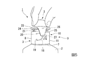
本実施形態の容器1は、図1に示すように、液状または粉状の内容物を収容可能な容器本体2と、容器本体2に装着される計量キャップ3とを備える。
Hereinafter, an example of the container of the present invention will be shown and described.
As shown in FIG. 1, the
容器本体2は、柔軟剤、液体洗剤等の液体あるいは粉末状洗剤や粉末状柔軟剤等の粉体を収容可能なボトル型の中空容器である。容器本体2は、図1及び図2に示すように、略四角形状の底壁4と、底壁4の縁部から立ち上がる側壁5と、側壁5の先端から上方に向かって徐々に縮径するように延びる肩部6と、肩部6の中央の上端から突設された円筒状の突設筒部7と、突設筒部7に螺合装着されるノズル中栓8とから構成されている。
突設筒部7の外周面には、ネジ部7aが形成されている。容器本体2の上部には、突設筒部7にノズル中栓8が螺合装着されることで円筒状の口頸部9が形成される。
The
A threaded
ノズル中栓8は、突設筒部7に螺合される円筒状の筒壁部10を有している。
筒壁部10は、内周面における下部にネジ部11aを設けた外筒壁11と、外筒壁11の内周側に接続壁12を介して下方に延設された内筒壁13とを有している。
The nozzle
The
内筒壁13は、外筒壁11の下端より若干下方まで達するように外筒壁11と平行に延出されている。内筒壁13の下端には傾斜面16aを有する底壁部16が設けられており、底壁部16には注出口16bが偏在して形成されている。すなわち、口頸部9の内側に注出口16bが偏在して形成されている。底壁部16における注出口16bの周縁部には注出筒17が立設されている。
The
底壁部16において注出口16bが偏在しているため、注出口16bの周りに立設された注出筒17も内筒壁13内で偏在している。注出筒17には、その側壁の中心軸線C1側に縦方向にスリット状の開口部17bが形成されている。さらに注出筒17は、上端部が中心軸線C1に向かって低くなるように傾斜した面17aが形成されるように斜め方向に切除されている。
Since the
ノズル中栓8は、内筒壁13が突設筒部7の内側に挿入され、外筒壁11のネジ部11aが容器本体2の突設筒部7のネジ部7aに螺合されることで、容器本体2の突設筒部7に着脱自在に装着されている。
また、ノズル中栓8には、外筒壁11と内筒壁13との間の接続壁12の下面から垂下された筒状のシールリップ部15が形成されている。これにより、ノズル中栓8を容器本体2の突設筒部7に螺合により装着した状態において、シールリップ部15が突設筒部7の開口部に密に挿入されることで、突設筒部7の開口部が液密に閉塞される。
In the
Further, the
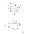
ノズル中栓8における外筒壁11の外周面、すなわち口頸部9の外周面には、中心軸線C1に対して対称位置(周方向対称位置)となるように、2つの案内凸条部18が形成されている。
案内凸条部18は、図2(a)及び図3に示すように、上下方向に延び、かつ計量キャップ3の回動方向(口頸部9の周方向)に傾斜している。より具体的には、この例の案内凸条部18は、ほぼ計量キャップ3の回動方向に延びる凸条からなる第1案内部18aと、第1案内部18aの右側端部から斜め上方に傾斜して延びる第2案内部18bとを備え、全体として下方に凸の略円弧状となっている。
Two
As shown in FIGS. 2A and 3, the
案内凸条部18は、外筒壁11の軸周りにおいて、平面視における中心軸線C1を中心とする15°〜20°の範囲内に形成されている。
案内凸条部18における第1案内部18aの軸周りの長さ(周方向の長さ)は、後述する第1係合凸部20の軸周りの長さ(周方向の長さ)とほぼ同等になっている。また、計量キャップ3の回動方向(周方向)に対する案内凸条部18における第2案内部18bの傾斜角は、例えば40〜70゜とされる。
The
The length around the axis of the
また、ノズル中栓8における外筒壁11の外周面には、案内凸条部18の左側端部から上方に延び、径方向の外方に突出するストッパー部19が形成されている。ストッパー部19が形成されていることにより、口頸部9に装着した状態の計量キャップ3を、平面視で軸周りに時計回り(右回り)に回動しようとすると、後述する案内突起27がストッパー部19に当接し、それ以上は回動しない。そのため、計量キャップ3が平面視で軸周りに時計回りに回動して後述する第1係合凸部20と第2係合凸部26の係合が解除されることが抑制されることで、計量キャップ3が口頸部9から予期せず外れることが抑制される。
Further, a
また、ノズル中栓8における外筒壁11の外周面、すなわち口頸部9の外周面における案内凸条部18よりも上方の部分には、径方向の外方に突出し、計量キャップ3の回動方向に延びる凸条からなる第1係合凸部20が形成されている。
第1係合凸部20は、外筒壁11の軸周りにおいて、平面視における中心軸線C1を中心とする15°〜20°の範囲内に形成されている。
Further, the outer peripheral surface of the outer
The first engaging
計量キャップ3は、図4に示すように、円筒状の計量筒部21と、計量筒部21の一側開口端を閉じる蓋部22と、計量筒部21の周面から外方に張り出した平面視円環状の張出板部23と、張出板部23の外縁部から垂下された延出片からなり、計量キャップ3の装着時に筒壁部10の外面に沿わせられる2つの外壁部25と、を備えている。このように、計量キャップ3は、有蓋円筒形状で、高さ方向の中央に外方に張り出す張出板部23を有している。また、張出板部23の内周縁部には、下方に突出するリング部24が形成されている。
なお、張出板部23の外壁部25より外側には、張出板部の外縁部から外側に突出した突出部が形成されていてもよい。
As shown in FIG. 4, the measuring
In addition, the protrusion part which protruded outside from the outer edge part of the overhang | projection board part may be formed in the outer side from the
計量筒部21は、注出筒17を囲むように、その下端側の一部がノズル中栓8の筒壁部10に挿入される。
計量筒部21の周壁における2つの外壁部25の間の部分には、図4(c)に示すように、計量用の目盛線と容量表示用の数字を備えた目盛部21bが印刷、刻印等の手段により形成されている。これにより、計量キャップ3を倒立させた状態で、計量筒部21の開口部21aから注入された液体等の内容物の量を把握することができる。
張出板部23は、計量筒部21の周面から全周にわたって外方に張り出して平面視形状が円環状となっており、計量キャップ3が口頸部9に装着される際に、口頸部9におけるノズル中栓8の筒壁部10上端の開口部に被せられる。また、リング部24が筒壁部10の開口部に密に挿入されることで、筒壁部10の開口部が液密に閉塞される。
A part of the lower end side of the measuring
As shown in FIG. 4C, a
The projecting
外壁部25は、下端に向かって幅が狭くなっている正面視舌型の薄型片であり、その下端部25aは正面視曲線状になっている。
2つの外壁部25は、張出板部23の周回りに180゜間隔で、すなわち計量キャップ3が口頸部9に装着されたときに中心軸線C1に対して対称位置(周方向対称位置)となるように軸周りに離間して形成されている。2つの外壁部25は、計量キャップ3の装着時に、筒壁部10の外周面における案内凸条部18及び第1係合凸部20が形成された部分に沿わせられる。
The
The two
計量キャップ3における外壁部25の内面には、計量キャップ3の装着時に外筒壁11の第1係合凸部20に係合する第2係合凸部26と、外筒壁11の案内凸条部18の上面に接する案内突起27が形成されている。
On the inner surface of the
第2係合凸部26は、図2(a)に示すように、外壁部25の内面において、計量キャップ3を口頸部9に装着したときに外筒壁11の第1係合凸部20の下側に係合するように形成されている。第1係合凸部20及び第2係合凸部26により係合部28が形成される。計量キャップ3の装着時に係合部28の第1係合凸部20と第2係合凸部26が係合することで、口頸部9に対する計量キャップ3の相対的な上方移動を規制することができる。これにより、装着した計量キャップ3が予期せず上方に抜けることを抑制できる。
As shown in FIG. 2A, the second engaging
案内突起27は、外壁部25の内面における第2係合凸部26よりも下方の部分において、計量キャップ3を口頸部9に装着したときに、外筒壁11の案内凸条部18における第1案内部18aの上面に接するように形成されている。
When the measuring
計量キャップ3は、口頸部9に装着された状態において平面視で軸周りに反時計回り(左回り)に回動できるようになっている。口頸部9に装着した計量キャップ3を平面視で軸周りに反時計回りに回動させたときには、案内突起27は案内凸条部18の上面を摺動するようになっている。一方、計量キャップ3は、前記したように、口頸部9に装着された状態において平面視で軸周りに時計回り(右回り)に回動させると、案内突起27がストッパー部19に当接してそれ以上回動しないようになっている。
The measuring
この例の案内突起27の正面視形状は、円形状になっている。
本発明では、案内突起が案内凸条部の上面を摺動しやすい点では、案内突起の正面視形状は円形状が好ましい。なお、案内突起が案内凸条部の上面を摺動できる範囲であれば、案内突起の正面視形状は円形状以外の形状であってもよい。
The front view shape of the
In the present invention, the front view shape of the guide projection is preferably circular in that the guide projection easily slides on the upper surface of the guide protrusion. In addition, as long as the guide protrusion is within a range in which the upper surface of the guide protrusion can slide, the shape of the guide protrusion in front view may be a shape other than a circular shape.
外壁部25は、弾性が付与されていることが好ましい。これにより、計量キャップ3の装着時に、係合部28の第1係合凸部20と第2係合凸部26とを容易に係合させることができる。
外壁部25に弾性が付与する態様としては、特に限定されず、例えば、弾性を有する樹脂によって外壁部25を形成する態様が挙げられる。
The
An aspect in which elasticity is imparted to the
(製造方法)
容器本体2の底壁4、側壁5、肩部6及び突設筒部7の製造方法としては、例えばポリエチレン等のオレフィン系合成樹脂を用いたブロー成型等により一体として成型する方法が挙げられる。容器本体2のノズル中栓8の製造方法としては、例えばポリプロピレン等のオレフィン系合成樹脂を用いた射出成型により一体として成型する方法が挙げられる。計量キャップ3の製造方法としては、例えばポリエチレン等のオレフィン系合成樹脂を用いた射出成型により一体として成型する方法が挙げられる。
なお、容器本体2及び計量キャップ3の製造方法は、前記した方法には限定されない。
(Production method)
As a manufacturing method of the
In addition, the manufacturing method of the container
(作用効果)
以下、容器1における計量キャップ3の取り外し操作、計量操作及び取り付け操作について説明する。
使用前の容器1においては、図2(b)に示すように、容器本体2内に内容物が収容された状態で、注出筒17を上向きとしてノズル中栓8の内筒壁13が突設筒部7に装着される。突設筒部7の開口部は、ノズル中栓8のシールリップ部15によって液密に閉塞されるため、突設筒部7のネジ部7aとノズル中栓8のネジ部11aの螺合部分を介する液漏れが防止される。
(Function and effect)
Hereinafter, the removal operation, the measurement operation, and the attachment operation of the
In the
口頸部9のノズル中栓8に計量キャップ3が装着された状態においては、図2(a)に示すように、計量キャップ3の2つの外壁部25が、筒壁部10の外周面における案内凸条部18及び第1係合凸部20が形成された部分に沿わせられている。そして、2つの外壁部25によってノズル中栓8の筒壁部10が挟み込まれるようになっている。
また、この状態では、口頸部9の外周面に形成された第1係合凸部20の下面に、計量キャップ3に形成された第2係合凸部26が係合している。これにより、口頸部9に対する計量キャップ3の相対的な上方移動が規制されている。
In a state where the measuring
Further, in this state, the second engaging
また、計量キャップ3に形成された案内突起27は、口頸部9の外周面に形成された案内凸条部18における第1案内部18aの上面に接している。この例の口頸部9の外周面には、案内凸条部18の左側端部から上方に延びるストッパー部19が形成されているため、口頸部9に装着した計量キャップ3を平面視で軸周り時計回りに回動しようとしても、案内突起27がストッパー部19に当接してそれ以上回動しない。そのため、計量キャップ3が予期せず軸周りに時計方向に回動して第1係合凸部20と第2係合凸部26の係合が解除されることが抑制され、その結果、計量キャップ3が口頸部9から予期せず外れることが抑制される。
Further, the
容器1を使用する際は、計量キャップ3の上部を指で摘み、計量キャップ3を平面視で軸周りに反時計回りに回動させる。このとき、図5に示すように、計量キャップ3の案内突起27が案内凸条部18における第1案内部18aの上面を摺動し、また第2係合凸部26が第1係合凸部20の下面を摺動して第1係合凸部20と第2係合凸部26の係合が解除される。さらに計量キャップ3を反時計周りに回動させることで、案内突起27が案内凸条部18における第2案内部18bの上面を摺動し、計量キャップ3を斜め上方に移動させる力が作用する。これにより、図5の矢印aに示すように案内突起27が案内凸条部18に沿ってせり上がり、その結果として計量キャップ3が回動しつつ斜め上方に移動することで、計量キャップ3を取り外すことができる。
When the
その後、図4(c)に示すように計量キャップ3を倒立させ、ノズル中栓8の注出筒17の先端を下向きとするように容器本体2を傾けて、容器本体2内の内容物を注出口16bから注出筒17を通じて計量筒部21に注入する。計量キャップ3の計量筒部21への内容物の注入量は、目盛部21bにより把握することができる。
計量操作を行う際の計量キャップ3では、目盛部21bの周囲に存在するのは、張出板部23の周方向対称位置に設けられた2つの外壁部25,25のみである。そのため、外壁部25,25の間から目盛部21bが視認しやすく、計量筒部21に収容した内容物の量を正確に把握することができる。
計量を終えて内容物を使用した後は、筒壁部10の外周面における案内凸条部18及び第1係合凸部20が形成された部分に外壁部25の位置を合わせつつ、図6の矢印bに示すように、計量筒部21をノズル中栓8の筒壁部10に挿入して装着する。
Thereafter, as shown in FIG. 4C, the measuring
In the measuring
After measuring and using the contents, the position of the
以上説明した本発明の容器においては、キャップの外壁部の内面と口頸部の外周面に形成された係合部の作用によって、口頸部に対するキャップの相対的な上方移動が規制されるため、容器本体に収容された内容物の漏れを充分に抑制できる。
また、本発明の容器では、口頸部に装着したキャップを容易に軸周りに回動させることができ、そのときに該キャップの案内突起が口頸部の案内凸条部の上面を摺動することでキャップがせり上がるため、キャップの取り外しが容易である。また、従来のネジ部を介して螺合装着するキャップは取り外す際に軸周りに何周も回動させる必要があるのに対して、本発明の容器ではキャップを軸周りに数分の一周回動させるだけで容易に取り外すことができる。
また、本発明の容器では、キャップの外壁部の位置を行いつつ、口頸部に上方から容易にキャップを装着することができる。
In the container of the present invention described above, the relative upward movement of the cap with respect to the mouth and neck is restricted by the action of the engaging portions formed on the inner surface of the outer wall of the cap and the outer peripheral surface of the mouth and neck. The leakage of the contents accommodated in the container body can be sufficiently suppressed.
In the container of the present invention, the cap attached to the mouth and neck portion can be easily rotated around the axis, and at that time, the guide projection of the cap slides on the upper surface of the guide ridge portion of the mouth and neck portion. By doing so, the cap rises, so that the cap can be easily removed. In addition, a cap that is screwed in via a conventional threaded portion needs to be rotated around its axis when it is removed, whereas in the container of the present invention, the cap is rotated a few times around its axis. It can be easily removed just by moving it.
In the container of the present invention, the cap can be easily attached to the mouth and neck portion from above while performing the position of the outer wall portion of the cap.
なお、本発明の容器は、前記した容器1には限定されない。
例えば、本発明の容器は、図7に例示した容器1Aであってもよい。図7における図2(a)と同じ部分は同符号を付して説明を省略する。容器1Aは、口頸部9の代わりに口頸部9Aを備える以外は、容器1と同じである。
口頸部9Aは、案内凸条部18の代わりに、案内凸条部18における第1案内部18aの左側端部から上下方向に延び、かつ計量キャップ3の回動方向に傾斜した第3案内部18cをさらに有する案内凸条部18Aが形成されたノズル中栓8Aを備える以外は、口頸部9と同じである。
The container of the present invention is not limited to the
For example, the
The
容器1Aにおいては、口頸部9Aに装着した計量キャップ3を平面視で軸周りに時計回りに回動させた場合にも、案内突起27が案内凸条部18Aにおける第3案内部18cの上面を摺動することで、反時計回りに回動させた場合と同様に計量キャップ3がせり上がるため計量キャップ3を容易に取り外すことができる。
In the
容器1Aにおいては、第1係合凸部20における、正面視で周方向における案内凸条部18Aの底部に対応する位置から左端までの長さが、当該位置から右端までの長さよりも長くなるようにしてもよい。この場合、装着した計量キャップ3を平面視で軸周りに時計回りに回動させたときには第1係合凸部20と第2係合凸部26との係合が外れやすく、反時計回りに回動させたときには第1係合凸部20と第2係合凸部26との係合が外れにくくなる。これにより、計量キャップ3を取り外す際の計量キャップ3の回動方向を規制することができる。
計量キャップ3を軸周りにどちらに回動させても計量キャップ3を取り外すことができるようにする場合は、第1係合凸部20における、正面視で周方向における案内凸条部18Aの底部に対応する位置から左端までの長さと、当該位置から右端までの長さを等しくして、軸周りの両方向への回動しやすさが同じになるようにすればよい。
In the
In the case where the measuring
また、本発明の容器は、図8に例示した容器1Bであってもよい。図8における図2(a)と同じ部分は同符号を付して説明を省略する。容器1Bは、計量キャップ3の代わりに計量キャップ3Aを備える以外は、容器1と同じである。
計量キャップ3Aは、延出片からなる外壁部25の代わりに、張出板部23の外縁部の全周から垂下された円筒状の外壁部25Aを備える以外は、計量キャップ3と同じである。
Moreover, the
The measuring
容器1Bにおいても、容器1と同様に、容器本体2に収容された内容物の漏れを充分に抑制でき、また口頸部9に装着された計量キャップ3Aを回動させることで容易に計量キャップ3Aを取り外すことができる。また、容器1Bでは、容器1と同様に、計量キャップ3Aの装着も容易である。
容器1Bのような、筒状の外壁部を備えるキャップを備える容器は、計量筒部を有さず、外壁部よりも外側から目盛部を視認する必要がない場合等に有用である。計量筒部を備える計量キャップを備える容器の場合は、目盛部の視認性の点から、容器1、1Aのような延出片からなる外壁部を有する計量キャップを備える容器が好ましい。
Similarly to the
A container including a cap having a cylindrical outer wall portion, such as the
また、本発明の容器においては、案内凸条部と案内突起の数は、特に限定されず、例えば、三対以上であってもよい。また、口頸部の外周面及び外壁部の内面において、案内凸条部と案内突起が形成される位置は、口頸部の軸線に対して対称となる位置には限定されない。
本発明の容器におけるキャップが延出片からなる外壁部を備える場合、該外壁部の数は、案内凸条部と案内突起の数に応じて適宜設定すればよい。また、延出片からなる外壁部の場合、その正面視形状は舌型には限定されず、例えば、矩形状、半円状等であってもよい。
Moreover, in the container of this invention, the number of a guide protrusion and a guide protrusion is not specifically limited, For example, three or more pairs may be sufficient. In addition, the positions at which the guide protrusions and the guide protrusions are formed on the outer peripheral surface of the mouth / neck portion and the inner surface of the outer wall portion are not limited to positions that are symmetrical with respect to the axis of the mouth / neck portion.
When the cap in the container of the present invention includes an outer wall portion formed of an extending piece, the number of the outer wall portions may be set as appropriate according to the number of guide protrusions and guide protrusions. Moreover, in the case of the outer wall part which consists of an extending piece, the front view shape is not limited to a tongue type, For example, rectangular shape, semicircle shape, etc. may be sufficient.
本発明の容器においては、口頸部の外周面及び外壁部の内面において、案内凸条部及び案内突起部と、係合部の位置は特に限定されない。例えば、口頸部の外周面及び外壁部の内面において、案内凸条部及び案内突起部よりも下方に係合部が形成されていてもよい。
また、本発明の容器は、計量機能を有しないキャップを備えるものであってもよい。
また、本発明の容器は、ノズル中栓を有しない容器であってもよい。
In the container of the present invention, the positions of the guide ridges, the guide protrusions, and the engaging portions are not particularly limited on the outer peripheral surface of the mouth / neck portion and the inner surface of the outer wall portion. For example, the engaging part may be formed below the guide ridge part and the guide projection part on the outer peripheral surface of the mouth and neck part and the inner surface of the outer wall part.
Moreover, the container of this invention may be equipped with the cap which does not have a measurement function.
The container of the present invention may be a container that does not have a nozzle plug.
また、本発明の容器においては、口頸部は円筒状には限定されない。例えば、軸方向に対して垂直方向に切断した断面形状が、円における一部が切り欠かれた形状や楕円状等の口頸部を備える容器であってもよい。
具体的には、例えば、図9に例示した容器1Cであってもよい。図9における図1と同じ部分には同符号を付して説明を省略する。容器1Cは、口頸部9の代わりに口頸部9Bを備える以外は容器1と同じである。口頸部9Bは、突設筒部とノズル中栓が一体に形成され、かつ軸方向に対して垂直方向に切断した断面形状が、円形における両方の側面側(対向する2つの案内凸条部18の間)で切り欠かれた形状である以外は、口頸部9と同じである。
容器1Cにおいても、容器1と同様に、容器本体2に収容された内容物の漏れを充分に抑制でき、また口頸部9Bに装着された計量キャップ3を回動させることで容易に計量キャップ3を取り外すことができる。また、容器1Cでは、容器1と同様に、計量キャップ3の装着も容易である。
Further, in the container of the present invention, the mouth and neck portion is not limited to a cylindrical shape. For example, the cross-sectional shape cut | disconnected perpendicularly | vertically with respect to the axial direction may be a container provided with mouth neck parts, such as a shape where a part in a circle was notched, or an ellipse.
Specifically, for example, the
Similarly to the
1,1A〜1C 容器
2 容器本体
3,3A 計量キャップ
7 突設筒部
8 ノズル中栓
9,9A,9B 口頸部
10 筒壁部
18,18A 案内凸条部
18a 第1案内部
18b 第2案内部
18c 第3案内部
19 ストッパー部
20 第1係合凸部
21 計量筒部
25,25A 外壁部
26 第2係合凸部
27 案内突起
28 係合部
1, 1A to
Claims (3)
前記キャップは、前記口頸部に装着されたときに前記口頸部の外周面に沿わせられる外壁部を備え、前記口頸部に装着された状態で前記口頸部の軸周りの少なくとも一方向に回動でき、
前記外壁部の内面と前記口頸部の外周面には、前記口頸部に対する前記キャップの相対的な上方移動を規制する係合部が形成され、
前記口頸部の外周面には、上下方向に延び、かつ前記キャップの回動方向に傾斜した案内凸条部が形成され、
前記外壁部の内面には、前記キャップが前記口頸部に装着されたときに前記案内凸条部の上面に接し、前記キャップが前記口頸部に装着された状態で回動されたときに前記案内凸条部の上面を摺動する案内突起が形成されている、容器。 A container having a mouth and neck, and a container body capable of containing liquid or powder-like contents, and a cap detachably provided on the mouth and neck,
The cap includes an outer wall portion that is fitted along an outer peripheral surface of the mouth / neck portion when attached to the mouth / neck portion, and is at least one around an axis of the mouth / neck portion in a state of being attached to the mouth / neck portion. Can rotate in the direction,
On the inner surface of the outer wall portion and the outer peripheral surface of the mouth-and-neck portion, an engaging portion that restricts the relative upward movement of the cap with respect to the mouth-and-neck portion is formed,
On the outer peripheral surface of the mouth-and-neck portion is formed a guide ridge extending in the vertical direction and inclined in the rotation direction of the cap,
When the cap is attached to the mouth and neck, the inner surface of the outer wall is in contact with the upper surface of the guide ridge, and when the cap is rotated while attached to the mouth and neck. The container in which the guide protrusion which slides on the upper surface of the said guide ridge part is formed.
Priority Applications (1)
| Application Number | Priority Date | Filing Date | Title |
|---|---|---|---|
| JP2014241176A JP2016101945A (en) | 2014-11-28 | 2014-11-28 | container |
Applications Claiming Priority (1)
| Application Number | Priority Date | Filing Date | Title |
|---|---|---|---|
| JP2014241176A JP2016101945A (en) | 2014-11-28 | 2014-11-28 | container |
Publications (1)
| Publication Number | Publication Date |
|---|---|
| JP2016101945A true JP2016101945A (en) | 2016-06-02 |
Family
ID=56088283
Family Applications (1)
| Application Number | Title | Priority Date | Filing Date |
|---|---|---|---|
| JP2014241176A Pending JP2016101945A (en) | 2014-11-28 | 2014-11-28 | container |
Country Status (1)
| Country | Link |
|---|---|
| JP (1) | JP2016101945A (en) |
Cited By (2)
| Publication number | Priority date | Publication date | Assignee | Title |
|---|---|---|---|---|
| JP2018043782A (en) * | 2016-09-16 | 2018-03-22 | 竹元 通則 | Lid body removable structure and storage container |
| CN110498129A (en) * | 2019-07-26 | 2019-11-26 | 杭州康鸿工贸有限公司 | The quick-opening structure of a kind of bottle cap and bottle and straw bottle with quick-opening structure |
-
2014
- 2014-11-28 JP JP2014241176A patent/JP2016101945A/en active Pending
Cited By (2)
| Publication number | Priority date | Publication date | Assignee | Title |
|---|---|---|---|---|
| JP2018043782A (en) * | 2016-09-16 | 2018-03-22 | 竹元 通則 | Lid body removable structure and storage container |
| CN110498129A (en) * | 2019-07-26 | 2019-11-26 | 杭州康鸿工贸有限公司 | The quick-opening structure of a kind of bottle cap and bottle and straw bottle with quick-opening structure |
Similar Documents
| Publication | Publication Date | Title |
|---|---|---|
| JP6497801B2 (en) | Weighing container | |
| US8899437B2 (en) | Closure with integrated dosage cup | |
| JP2016101945A (en) | container | |
| JP6934339B2 (en) | Weighing cap | |
| JP2014196130A (en) | Pouring container | |
| JP2017149476A (en) | Liquid measuring container | |
| JP6175509B2 (en) | Weighing container | |
| JP6249898B2 (en) | Weighing container | |
| JP2008162656A (en) | Cap | |
| JP6994986B2 (en) | container | |
| JP6611332B2 (en) | Weighing container | |
| JP6465483B2 (en) | container | |
| JP2017154749A (en) | Liquid measurement container | |
| JP2017149478A (en) | Pour-out plug with measuring cap | |
| JP7394616B2 (en) | measuring cap | |
| JP2003212256A (en) | Plastic cap with measuring function | |
| JP6979897B2 (en) | container | |
| JP6104153B2 (en) | Liquid dispensing container | |
| JP5216043B2 (en) | Opening and closing device for taking out goods in container | |
| JP6373118B2 (en) | Weighing container | |
| JP2006327671A (en) | Metering cap | |
| JP2023151504A (en) | measuring container | |
| JP6051098B2 (en) | Weighing cap | |
| JP6501656B2 (en) | Measuring cap | |
| JP6125994B2 (en) | Dripping container |