JP2016101773A - Guide device - Google Patents
Guide device Download PDFInfo
- Publication number
- JP2016101773A JP2016101773A JP2014239699A JP2014239699A JP2016101773A JP 2016101773 A JP2016101773 A JP 2016101773A JP 2014239699 A JP2014239699 A JP 2014239699A JP 2014239699 A JP2014239699 A JP 2014239699A JP 2016101773 A JP2016101773 A JP 2016101773A
- Authority
- JP
- Japan
- Prior art keywords
- guide
- guide device
- unit
- frame
- monitor
- Prior art date
- Legal status (The legal status is an assumption and is not a legal conclusion. Google has not performed a legal analysis and makes no representation as to the accuracy of the status listed.)
- Pending
Links
Images


Abstract
Description
本発明は、ガイド装置に関する。 The present invention relates to a guide device.
従来から、車両等の移動体には、ナビゲーション装置、放送受信装置、音響装置等の情報処理装置が搭載されている。こうした情報処理装置には、画像を表示するモニタ部が一般的に備えられている。当該モニタ部は、例えば、車両のインストルメント・パネル内に設置される。 Conventionally, information processing apparatuses such as a navigation apparatus, a broadcast receiving apparatus, and an acoustic apparatus are mounted on a moving body such as a vehicle. Such an information processing apparatus is generally provided with a monitor unit that displays an image. The said monitor part is installed in the instrument panel of a vehicle, for example.
ここで、モニタ部をインストルメント・パネル内に設置する一つの方法として、モニタ部の下部を、前後方向に駆動するガイド装置のスライダに回転自在に取り付けて、モニタ部の下部を、前後方向への直線移動を可能にしたものがある。そして、この設置方法では、モニタ部の上部に取り付けた部材を、インストルメント・パネルに取り付けられた部材に成型された上下方向のガイド溝に係合させることにより、モニタ部の下部の前後方向への移動に追従して、モニタ部の上部を、当該ガイド溝に沿って上下方向へ移動させている。 Here, as one method of installing the monitor unit in the instrument panel, the lower part of the monitor unit is rotatably attached to a slider of a guide device that drives in the front-rear direction, and the lower part of the monitor unit is moved in the front-rear direction. There is one that enables linear movement. In this installation method, the member attached to the upper part of the monitor unit is engaged with the vertical guide groove formed in the member attached to the instrument panel, so that the lower part of the monitor unit is moved in the front-rear direction. The upper part of the monitor unit is moved in the vertical direction along the guide groove.
かかる設置方法では、モニタ部の下部を、ガイド装置のスライダにより利用者に対して前方向に直線移動させたときに、モニタ部の上部がガイド溝に沿って下方向に移動し、モニタ部の下部を利用者の手前にせり出すような姿勢(以下、「オープン姿勢」とも記す)にする。また、かかる設置方法では、モニタ部の下部を、ガイド装置のスライダにより利用者に対して後方向に直線移動させたときには、モニタ部の上部がガイド溝に沿って上方向に移動し、モニタ部の表示面がインストルメント・パネルの面とほぼ同一面を形成するような姿勢(以下、「クローズ姿勢」とも記す)にする。 In this installation method, when the lower part of the monitor unit is linearly moved forward with respect to the user by the slider of the guide device, the upper part of the monitor unit moves downward along the guide groove, The posture is such that the lower part protrudes in front of the user (hereinafter also referred to as “open posture”). Further, in this installation method, when the lower part of the monitor unit is linearly moved backward with respect to the user by the slider of the guide device, the upper part of the monitor unit moves upward along the guide groove, and the monitor unit In such a manner that the display surface forms substantially the same plane as the instrument panel surface (hereinafter also referred to as “closed posture”).
ところで、車両のインストルメント・パネルが傾斜している場合には、「クローズ姿勢」時においては、モニタ部の表示面もインストルメント・パネルの傾斜角度とほぼ同じ角度で、傾斜する。こうした「クローズ姿勢」のときに、モニタ部の表示面に太陽光などの光が映り込んだ際には、利用者は、当該光の反射で、表示面に表示されている画像の視認ができないことがある。 By the way, when the instrument panel of the vehicle is tilted, the display surface of the monitor unit is tilted at substantially the same angle as the tilt angle of the instrument panel in the “closed posture”. When light such as sunlight is reflected on the display surface of the monitor unit in such a “closed posture”, the user cannot visually recognize the image displayed on the display surface due to the reflection of the light. Sometimes.
こうした事態を回避するために、モニタ部の上部を利用者の手前に倒し、モニタ部の表示面を、クローズ姿勢から更に斜め下方向に傾けた姿勢(以下、「逆チルト姿勢」とも記す)にすると、これまで視認できなかった画像が、明瞭に視認することができることがある。しかしながら、上述したモニタ部の設置方法では、モニタ部を「逆チルト姿勢」にしようとすると、モニタ部の下部の移動が前後方向の直線移動のみであるため、モニタ部の下端部が、車両のインストルメント・パネルに干渉することがある。 In order to avoid such a situation, the upper part of the monitor unit is tilted toward the user and the display surface of the monitor unit is tilted further downward from the closed posture (hereinafter also referred to as “reverse tilt posture”). Then, an image that could not be viewed up to now may be clearly visible. However, in the above-described installation method of the monitor unit, when the monitor unit is set to the “reverse tilt posture”, the lower part of the monitor unit is moved only in the front-rear direction. May interfere with the instrument panel.
かかる干渉を避けるために、モニタ部の上下方向のサイズを小さくすることが考えられる。しかし、モニタ部の上下方向のサイズを小さくした場合には、表示面の画像表示領域を小さくしなければならない。また、モニタ部のサイズを小さくした場合には、「クローズ姿勢」時において、モニタ部の下端部とインストルメント・パネルとの間に隙間で生じてしまい、意匠デザインに悪影響を及ぼすことがある。 In order to avoid such interference, it is conceivable to reduce the vertical size of the monitor unit. However, when the vertical size of the monitor unit is reduced, the image display area on the display surface must be reduced. Further, when the size of the monitor unit is reduced, in the “closed posture”, a gap is generated between the lower end of the monitor unit and the instrument panel, which may adversely affect the design design.
そこで、モニタ部の上下方向のサイズを小さくすることなく、「逆チルト姿勢」を実現する技術が提案されている(特許文献1参照:以下、「従来例」と呼ぶ)。この従来例の技術では、モニタ部(表示パネル)の下側を、前後方向に駆動されるスライダに追従して移動する第1の軸回りに回転自在に支持するとともに、モニタ部の上側に取り付けられたレバーに設けられた第2の軸を、本体部の筐体に固定されたサブパネルに設けられたガイド溝に沿って移動させる機構になっている。そして、「クローズ姿勢」から、第1の軸を後方に移動させて、モニタ部の前面に位置する表示面が下方を向くように傾斜させるときに、第1の軸が後方及び上方に移動するようにしている。このように、この従来例の技術では、「逆チルト姿勢」時において、モニタ部の下部を上方に移動させることで、モニタ部の上下方向のサイズを小さくすることなく、モニタ部の下端部が車両のインストルメント・パネルに干渉しないようにしている。 Therefore, a technique for realizing a “reverse tilt posture” without reducing the vertical size of the monitor unit has been proposed (see Patent Document 1: hereinafter referred to as “conventional example”). In this conventional technique, the lower side of the monitor unit (display panel) is rotatably supported around a first axis that moves following a slider driven in the front-rear direction, and is attached to the upper side of the monitor unit. The second shaft provided in the provided lever is moved along a guide groove provided in the sub-panel fixed to the housing of the main body. Then, when the first axis is moved backward from the “closed posture” and the display surface located on the front surface of the monitor unit is inclined so as to face downward, the first axis moves backward and upward. I am doing so. As described above, in the technique of this conventional example, the lower end portion of the monitor unit can be moved without lowering the vertical size of the monitor unit by moving the lower part of the monitor unit upward during the “reverse tilt posture”. It does not interfere with the vehicle instrument panel.
上述した従来例の技術では、モニタ部の下部を駆動するガイド装置は、前後方向に移動するスライダ(メインフレーム)と、アーム(サブフレーム)とを備えている。当該アームは、アームの略中央で、スライダに立設されたアーム回転中心軸により、スライダに取り付けられている。そして、アームの一方の端に立接された第1の軸が、モニタ部の下部を回転自在に支持し、アームの他方の端に立接された軸に取り付けられたローラが、シャーシに固定されたローラガイドに設けられたカムに圧接されている。そして、スライダがシャーシの後部に移動すると、アームのローラが、ローラガイドの形状に沿って移動し、アームが、アーム回転中心軸を中心にして回転して、アームの一方の端に立接された第1の軸が上方に移動するようになっている。 In the above-described conventional technology, the guide device that drives the lower portion of the monitor unit includes a slider (main frame) that moves in the front-rear direction and an arm (sub-frame). The arm is attached to the slider at an approximate center of the arm by means of an arm rotation center axis standing on the slider. The first shaft standing on one end of the arm rotatably supports the lower part of the monitor unit, and the roller attached to the shaft standing on the other end of the arm is fixed to the chassis. The roller guide is pressed against a cam provided on the roller guide. Then, when the slider moves to the rear part of the chassis, the roller of the arm moves along the shape of the roller guide, and the arm rotates around the arm rotation center axis and is in contact with one end of the arm. The first shaft is moved upward.
こうした従来例の技術のガイド装置では、ガタに起因する、モニタ部の異音の発生や利用者の操作性の悪化を避けるため、アームのガタを防止する機構を備えているとともに、スライダのガタを防止する機能も備えていなければならない。このように、従来例の技術のガイド装置では、スライダに回転自在に取り付けられたアームが必須の構成要素であるとともに、当該アームやスライダのガタを防止する機構が必要になること等の理由から、部品点数が多くなっている。この結果、ガイド装置の製造コストが高価なものとなりやすい。 In order to avoid the generation of abnormal noise in the monitor unit and the deterioration of operability for the user due to the play, the conventional guide device of the prior art includes a mechanism for preventing the play of the arm and the backlash of the slider. It must also have a function to prevent this. As described above, in the conventional guide device, the arm that is rotatably attached to the slider is an indispensable component, and a mechanism that prevents the arm and the slider from rattling is necessary. The number of parts is increasing. As a result, the manufacturing cost of the guide device tends to be expensive.
このため、部品点数を極力少なくしたガイド装置の構成を採用して、モニタ部の上下方向のサイズを小さくすることなく、モニタ部の表示面を斜め下方向に傾けた姿勢を実現することができる技術が望まれている。かかる要請に応えることが、本発明が解決すべき課題の一つとして挙げられる。 For this reason, it is possible to realize a posture in which the display surface of the monitor unit is inclined obliquely downward without reducing the size of the monitor unit in the vertical direction by adopting a configuration of the guide device with as few parts as possible. Technology is desired. Meeting this requirement is one of the problems to be solved by the present invention.
請求項1に記載の発明は、筐体を回転自在に固定する複数の固定部を側端部に含み、前記側端部で前記筐体を支持する支持部と;前記支持部を駆動する駆動部と;前記支持部が駆動される方向をガイドするガイド部と;を備え、前記ガイド部には、前記支持部に取り付けられ、前記固定部に向かうにつれて下方に向けて傾斜するスロープ形状が設けられている、ことを特徴とするガイド装置である。
The invention according to
以下、本発明の一実施形態を、図1〜図15を参照して説明する。なお、以下の説明及び図面においては、同一又は同等の要素には同一の符号を付し、重複する説明を省略する。 Hereinafter, an embodiment of the present invention will be described with reference to FIGS. In the following description and drawings, the same or equivalent elements are denoted by the same reference numerals, and redundant description is omitted.
[構成]
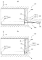
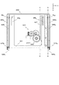
図1(A),(B)には、一実施形態に係る「ガイド装置」を備える情報処理装置100の外観図が示されている。ここで、本実施形態で使用する座標系(X,Y、Z)は、図示の通りに定義され、図1(A),(B)は、Y軸方向の手前側(−Y方向側)から視た場合の外観図である。本実施形態では、情報処理装置100は、車両のインストルメント・パネルIP内に配置される。図1(A),(B)により総合的に示されるように、情報処理装置100は、本体部200と、モニタ上部取付部材290とを備えている。また、情報処理装置100は、表示部320を有する表示装置300と、ガイド装置500とを備えている。
[Constitution]
1A and 1B are external views of an
図1(A),(B)に示されるように、情報処理装置100では、表示装置300の下部が、ガイド装置500に回転自在に支持されるとともに、表示装置300の上部が、モニタ上部取付部材290に接続されている。本実施形態では、図1(A)に示される表示装置300の姿勢を「フルオープン姿勢」といい、図1(B)に示される表示装置300の姿勢を「クローズ姿勢」ということにする。なお、本実施形態で使用する座標系(X,Y,Z)は、「クローズ姿勢」時において、表示装置300の表示部320の法線方向をX方向、表示部320の横方向をY方向、表示部320の縦方向をZ方向とする座標系となっている。
As shown in FIGS. 1A and 1B, in the
<本体部200の構成>
上記の本体部200の構成について、説明する。本体部200は、本体筐体210と、シャーシ部材250とを備えている。なお、シャーシ部材250は、収納部に対応している。
<Configuration of
The configuration of the
上記の本体筐体210は、例えば、中空の直方体形状をした鋼鉄製の部材であり、車両のインストルメント・パネル内に固定される。そして、+X方向側から視た本体筐体210の前面の下側(−Z方向側)には、ガイド装置500を収納可能な開口が形成されている。
The
上記のシャーシ部材250は、例えば、鋼鉄製の部材であり、XY平面に平行な底板、当該底板の−X方向側の側縁に連接されたYZ平面に平行な後板、当該底板の−Y方向側及び+Y方向側の側縁に連接されたXZ平面に平行は2つの側板が一体成形された部材である。こうして一体成形されたシャーシ部材250は、本体筐体210内の下側に固定される。
The
なお、シャーシ部材250には、ガイド装置500の構成要素の一部である後述する駆動部550、レール部5601,5602及び接触部5701,5702が固定されている。
The
また、本体部200には、情報処理装置100の機能を実行する不図示の部品等が装着されている。例えば、情報処理装置100がナビゲーション装置である場合には、本体部200には、ナビゲーション処理の機能を行う部品等が装着される。また、例えば、情報処理装置100が放送受信装置である場合には、本体部200には、放送受信処理の機能を行う部品等が装着される。ここで、当該機能を行う部品等は、本体筐体210に装着されるようにしてもよいし、シャーシ部材250に装着されるようにしてもよい。
The
<モニタ上部取付部材290>
次に、上記のモニタ上部取付部材290について、説明する。
<Monitor
Next, the monitor
上記のモニタ上部取付部材290は、情報処理装置100を+X方向側から視た場合に、「クローズ姿勢」時において、表示装置300の外縁を囲む枠状部分を含む部材である。このモニタ上部取付部材290は、本体筐体210の前面の−Y方向側に固定され、Z方向に延びる長方体形状の取付部と、本体筐体210の前面の+Y方向側に固定され、Z方向に延びる長方体形状の取付部(図1(A),(B)において不図示)とを含んで、一体成形されている。
The monitor
そして、本体筐体210の前面の−Y方向側に固定された長方体形状の+Y方向側には、図1(A),(B)に示した形状のガイド溝GR1が成型されている。また、本体筐体210の前面の+Y方向側に固定された長方体形状の−Y方向側には、ガイド溝GR1の形状と鏡面対称形状の不図示のガイド溝GR2が成型されている。
A guide groove GR 1 having the shape shown in FIGS. 1A and 1B is formed on the + Y direction side of the rectangular shape fixed to the −Y direction side of the front surface of the
<表示装置300の構成>
次いで、上記の表示装置300の構成について、説明する。表示装置300は、モニタ部310と、表示部320とを備えている。
<Configuration of
Next, the configuration of the
上記のモニタ部310は、略長方体形状の筐体であり、表示部320に画像を表示させる表示制御回路等が内蔵されている。モニタ部310の下部の−Y方向側には、Y方向を軸方向とする軸部材AX1が固定されている。また、モニタ部の下部の+Y方向側には、Y方向を軸方向とする不図示の軸部材AX2が固定されている。そして、当該軸部材AX1,AX2を利用して、モニタ部310の下部が、ガイド装置500に回転自在に支持されるようになっている。
The
また、モニタ部310の上部の−Y方向側には、−Y方向に突出した突起部材PR1が固定されている。また、モニタ部310の上部の+Y方向側には、+Y方向側に突出した不図示の突起部材PR2が固定されている。そして、突起部材PR1がモニタ上部取付部材290のガイド溝GR1に係合するとともに、突起部材PR2がモニタ上部取付部材290のガイド溝GR2に係合する。
Further, a protruding member PR 1 protruding in the −Y direction is fixed to the −Y direction side of the upper portion of the
上記の表示部320は、モニタ部310の前面に配置され、液晶パネル等の表示デバイスなどを備えて構成される。ここで、情報処理装置100が、ナビゲーション装置である場合には、表示部320は、地図表示等を利用した走行ルートの案内誘導用の画像を表示する。また、情報処理装置100が、放送受信装置である場合には、表示部320は、放送映像を再生表示する。
The
<ガイド装置500の構成>
次いで、上記のガイド装置500の構成について、説明する。
<Configuration of
Next, the configuration of the
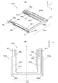
図2(A),(B)には、シャーシ部材250に収納されたガイド装置500の外観図が示されている。ここで、図2(A)は、シャーシ部材250及びガイド装置500を、図2(A)に示した座標系で表した斜視図である。また、図2(B)は、シャーシ部材250及びガイド装置500を、+Z方向側から視た平面図である。図2(A),(B)により総合的に示されるように、ガイド装置500は、フレーム部510と、駆動部550と、レール部5601,5602と、接触部5701,5702とを備えている。ここで、駆動部550、レール部5601,5602及び接触部5701,5702は、シャーシ部材250に配設されている。
2A and 2B are external views of the
《フレーム部510の構成》
上記のフレーム部510の構成について説明する。図3(A),(B)、図4(A),(B)及び図5には、「フルオープン姿勢」時のフレーム部510の外観図が示されている。ここで、図3(A)は、フレーム部510を、図3(A)に示した座標系で表した斜視図である。また、図3(B)は、フレーム部510を、+Z方向側から視た平面図である。また、図4(A)は、フレーム部510を、−Y方向側から視た側面図であり、図4(B)は、図4(A)に示した四角枠の部分の拡大図である。さらに、図5は、フレーム部510のA−A(図3(B)参照)断面図である。
<< Configuration of
The configuration of the
図3(A),(B)及び図4(A),(B)により総合的に示されるように、フレーム部510は、メインフレーム部材520と、サブフレーム部材5301,5302とを備えている。ここで、メインフレーム部材520は、支持部に対応し、サブフレーム部材5301,5302は、ガイド部に対応している。
As comprehensively shown in FIGS. 3A and 3B and FIGS. 4A and 4B, the
(メインフレーム部材520の構成)
上記のメインフレーム部材520の構成について説明する。
(Configuration of main frame member 520)
The configuration of the
メインフレーム部材520は、本実施形態では、鋼鉄製の部材であり、メインフレーム底面部521と、メインフレーム側面部5231,5232と、モニタ取付部5251,5252と、ラック部527とを有し、一体構造になっている。ここで、モニタ取付部5251,5252は、固定部に対応し、ラック部527は、変換部材に対応している。
In this embodiment, the
上記のメインフレーム底面部521は、「フルオープン姿勢」時において、XY平面と平行な平板を有するU字状の部材であり、U字の内側部分には、補強突条が形成されている。メインフレーム底面部521は、−Y方向側に配置され、X軸方向に沿って延びるXY平面と平行な面を有する長板状の底面部と、+Y方向側に配置され、X軸方向に沿って延びるXY平面と平行な面を有する底面部とを含んでいる。
The main frame
そして、−Y方向側の底面部の−X方向側には、略長方形状の板バネから成る付勢用バネBS1が成形され、+Y方向側の底面部の−X方向側には、略長方形状の板バネから成る付勢用バネBS2が成形されている。これらの付勢用バネBS1,BS2は、弾性力により、シャーシ部材250の底板に圧接している。かかる構造により、車両の振動等によるシャーシ部材250とメインフレーム部材520とのガタの発生を、防止している。
Then, in the -X direction side of the bottom portion of the -Y direction side, the biasing spring BS 1 consisting substantially rectangular leaf spring is molded, the + -X direction side of the bottom of the Y direction is substantially biasing spring BS 2 consisting of a rectangular leaf spring is molded. These urging springs BS 1 and BS 2 are in pressure contact with the bottom plate of the
また、+Y方向側の底面部には、X軸方向に沿って延びる溝LHが成形加工されている。当該溝LHには、シャーシ部材250に固定された規制用突出部PJ1,PJ2,PJ3が嵌入するようになっている(図2(A),(B)参照)。こうした構造により、メインフレーム部材520のX方向の移動範囲を規制するとともに、メインフレーム部材520のY方向の移動を規制している。
A groove LH extending along the X-axis direction is formed on the bottom surface portion on the + Y direction side. The restriction protrusions PJ1, PJ2, and PJ3 fixed to the
上記のメインフレーム側面部5231は、「フルオープン姿勢」時において、X軸方向に沿って延びるXZ平面と平行な面を有する細長板形状をしており、メインフレーム底面部521の−Y方向側の側縁に連接されている。当該メインフレーム側面部5231の−Y方向側の面には、サブフレーム部材5301が固定される。
The main
また、メインフレーム側面部5231の+X方向側の端部には、モニタ取付部5251が接続されている。また、メインフレーム側面部5231の−X方向の端部側には、ローラRL1が取り付けられている。
Further, a
上記のメインフレーム側面部5232は、「フルオープン姿勢」時において、X軸方向に沿って延びるXZ平面と平行な面を有する細長板形状をしており、メインフレーム底面部521の+Y方向側の側縁に連接されている。当該メインフレーム側面部5232の+Y方向側の面には、サブフレーム部材5302が固定される。
The main frame
また、メインフレーム側面部5232の+X方向側の端部には、モニタ取付部5252が接続されている。また、メインフレーム側面部5232の−X方向の端部側には、ローラRL2が取り付けられている。
Further, a
上記のモニタ取付部5251は、XZ平面と平行な面を有し、メインフレーム側面部5231の+X方向側の端部に接続されている。当該モニタ取付部5251には、軸穴HL1が形成されている。
The
上記のモニタ取付部5252は、XZ平面と平行な面を有し、メインフレーム側面部5232の+X方向側の端部に接続されている。当該モニタ取付部5252には、軸穴HL2が形成されている。
The
モニタ取付部5251の軸穴HL1に、モニタ部310の下部に固定された軸部材AX1が挿入され、モニタ取付部5252の軸穴HL2に、モニタ部310の下部に固定された軸部材AX2が挿入される。これにより、モニタ部310の下部が、ガイド装置500に回動自在に固定される。
The shaft member AX 1 fixed to the lower portion of the
上記のラック部527は、本実施形態では、メインフレーム底面部521における+Y方向側の底面部の−Y方向側の側縁に連接されている。当該ラック部527には、−Y方向側にラック歯が形成されている。かかるラック歯は、図5に示されるように、「フルオープン姿勢」時において、X軸方向に沿って延びるとともに、モニタ取付部5252に向かうにつれて下方(−Z方向側)傾斜している。かかるラック歯の傾斜の角度は、後述する第3ギア555の厚さに基づいて、予め定められる。
In the present embodiment, the
(サブフレーム部材5301,5302の構成)
次に、上記のサブフレーム部材5301,5302の構成について説明する。
(Configuration of
Next, the configuration of the
サブフレーム部材5301は、本実施形態では、鋼鉄製の部材であり、「フルオープン姿勢」時において、X軸方向に延びるXZ平面と平行な面を有する板状の部材である。当該サブフレーム部材5301は、図3(A),(B)及び図4(A),(B)により総合的に示されるように、メインフレーム部材520におけるメインフレーム側面部5231の−Y方向側の板面に固定される。
Subframe
サブフレーム部材5301の+Z方向側の上縁には、突条LP1が形成されている。本実施形態では、サブフレーム部材5301は、図4(A),(B)に示されるように、メインフレーム部510のモニタ取付部5251に向かうにつれて、段階的に下方に向けて傾斜するように、第1水平部分H1、第1傾斜部分S1、第2水平部分H2、第2傾斜部分S2、第3水平部分H3が順次形成される複数段を含んでいる。このため、突条LP1は、+X方向側において、多段スロープ形状を有している。このようにして形成されているサブフレーム部材5301におけるスロープ形状の突条LP1は、接触部5701により、挟持される。
On the upper edge of the + Z direction side of the
サブフレーム部材5302は、本実施形態では、上述したサブフレーム部材5301と同様に、鋼鉄製の部材であり、「フルオープン姿勢」時において、X軸方向に延びるXZ平面と平行な面を有する板状の部材である。当該サブフレーム部材5302は、図3(A),(B)及び図5により総合的に示されるように、メインフレーム部材520におけるメインフレーム側面部5232の+Y方向側の板面に固定される。
In the present embodiment, the
サブフレーム部材5302は、XZ平面に対してサブフレーム部材5301と対称的に形成され、サブフレーム部材5302の+Z方向側の上縁には、突条LP2が形成されている。サブフレーム部材5302は、メインフレーム部510のモニタ取付部5252に向かうにつれて下方に向けて傾斜するように、第1水平部分H1、第1傾斜部分S1、第2水平部分H2、第2傾斜部分S2、第3水平部分H3が順次形成される複数段を含んでいる。このため、突条LP2は、+X方向側において、多段スロープ形状を有している。このようにして形成されているサブフレーム部材5302におけるスロープ形状のLP2は、接触部5702により、挟持される。
The
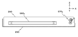
引き続き、シャーシ部材250に配置される駆動部550、レール部5601,5602、接触部5701,5702の構成を、図6(A),(B)及び図7等を更に参照して、順次説明する。ここで、図6(A)は、シャーシ部材250に取り付けられた、フレーム部510を除くガイド装置500を、図6(A)に示した座標系で表した斜視図である。また、図6(B)は、シャーシ部材250に取り付けられた、フレーム部510を除くガイド装置500を、+Z方向側から視た平面図である。さらに、図7は、フレーム部510を除くガイド装置500のB−B(図6(B)参照)断面図である。
Subsequently, the configuration of the
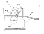
《駆動部550の構成》
上記の駆動部550の構成について説明する。駆動部550は、図2(A),(B)及び図6(A),(B)より総合的に示されるように、シャーシ部材250の底板に配置される。駆動部550は、図8に示されるように、X方向を軸方向とする樹脂製のモータ軸MAを有するモータ551と、第1同軸ギア553と、第2同軸ギア554と、第3ギア555とを備えている。なお、第3ギア555は、回転部材、外歯歯車部材に対応している。ここで、図8は、駆動部550を+Z方向側から視た図である。
<< Configuration of
The configuration of the
上記のモータ551は、不図示の入力部から送られた利用者による表示装置300の開閉指定に従って、所定の回転速度で、螺旋状の溝が形成されたモータ軸MAを、正回転又は逆回転させる。
The
上記の第1同軸ギア553は、樹脂製の部材であり、大径ギアと小径ギアとが結合された同軸ギアである。第1同軸ギア553の大径ギアには、Z軸と平行な軸を中心とする円周上にギア歯が形成され、第1同軸ギア553の小径ギアには、Z軸と平行な軸を中心とする円周上にギア歯が形成されている。ここで、第1同軸ギア553の大径ギアの径は、第1同軸ギア553の小径ギアの径よりも大きくなっている。
The first
第1同軸ギア553の大径ギアにおけるギア歯は、モータ551に取り付けられたモータ軸MAの溝と噛合している。
The gear teeth in the large-diameter gear of the first
上記の第2同軸ギア554は、樹脂製の部材であり、大径ギアと小径ギアとが結合された同軸ギアである。第2同軸ギア554の大径ギアには、Z軸と平行な軸を中心とする円周上にギア歯が形成され、第2同軸ギア554の小径ギアには、Z軸と平行な軸を中心とする円周上にギア歯が形成されている。ここで、第2同軸ギア554の大径ギアの径は、第2同軸ギア554の小径ギアの径よりも大きくなっている。
The second
第2同軸ギア554の大径ギアにおけるギア歯は、第1同軸ギア553の小径ギアにおけるギア歯と噛合している。
The gear teeth in the large diameter gear of the second
上記の第3ギア555は、樹脂製の部材であり、Y軸と平行な軸を中心とする円周上にギア歯が形成されている。第3ギア555のギア歯は、第2同軸ギア554の小径ギアにおけるギア歯と噛合しているとともに、ラック部527におけるラック歯と噛合している。このため、モータ551のモータ軸MAが、正回転又は逆回転すると、ラック部527を要素とするフレーム部510が、X軸方向に沿って移動するようになっている。
The
本実施形態では、ラック部527のラック歯の厚さは、第3ギア555のギア歯の厚さより薄くなっている。このため、本実施形態では、図9に模式的に示す「第3ギア555のギア歯」と「ラック部527のラック歯」との噛み合い位置における断面図にから見て取れるように、第3ギア555のギア歯の歯すじと、ラック歯の歯すじが平行でなくても、第3ギア555のギア歯とラック歯との間のクリアランスが確保されている。この結果、第3ギアのギア歯とラック部527のラック歯との噛合が確保される。
In the present embodiment, the thickness of the rack teeth of the
なお、第3ギア555の厚さは、フレーム部510の全可動範囲で、第3ギア555のギア歯とラック部527のラック歯との噛合が確保する観点から、実験、シミュレーション、経験等に基づいて、予め定められる。
It should be noted that the thickness of the
《レール部5601,5602の構成》
次いで、上記のレール部5601,5602の構成について説明する。
<< Configuration of
Next, the configuration of the
レール部5601は、本実施形態では、鋼鉄製の部材であり、図2(A),(B)、図6(A),(B)及び図7により総合的に示されるように、シャーシ部材250における−Y方向側の側板に配置される。レール部5601のYZ平面における断面は、開口側が互いに突き合わさせた略U字状の部材であり、当該レール部5601の長手方向は、X方向になっている。そして、当該レール部5601には、フレーム部510のローラRL1が係合している。
In this embodiment, the
レール部5602は、本実施形態では、上述したレール部5601と同様に、鋼鉄製の部材であり、シャーシ部材250における+Y方向側の側板に配置される。当該レール部5602は、XZ平面に対して、レール部5601と対称的に形成されている。そして、当該レール部5602には、フレーム部510のローラRL2が係合している。
In the present embodiment, the
《接触部5701,5702の構成》
次に、上記の接触部5701,5702の構成について説明する。
<< Configuration of
Next, the configuration of the
接触部5701は、図2(A),(B)、図6(A),(B)及び図7により総合的に示されるように、シャーシ部材250における−Y方向側の側板の+X方向側に配置される。また、接触部5702は、シャーシ部材250における+Y方向側の側板の+X方向側に配置される。
As shown in FIGS. 2A, 2 </ b> B, 6 </ b> A, 6 </ b> B, and 7, the
まず、接触部5702の構成について説明する。接触部5702は、図10に示されるように、ローラ部材5712と、規制用部材5722と、トーションバネ5732とを備えている。なお、ローラ部材5712及び規制用部材5722は挟持部に対応し、トーションバネ5732は振動防止部に対応している。ここで、図10は、接触部5702を−Y方向側から視た図である。
First, the configuration of the
上記のローラ部材5712は、例えば、樹脂製の部材であり、Y方向を軸方向にして、シャーシ部材250に回転可能に取り付けられる。当該ローラ部材5712は、サブフレーム部材5302の+Z方向側の上縁に形成されたスロープ形状の突条LP2の−Z方向側と接している。
The roller member 571 2 is a resin member, for example, and is rotatably attached to the
上記の規制用部材5722は、例えば、樹脂製の部材であり、シャーシ部材250に回転可能に取り付けられた円柱形状と、当該円柱形状の−Y方向側に図10に示す形状とが一体となって成型加工されている。当該規制用部材5722は、サブフレーム部材5302の+Z方向側の上縁に形成されたスロープ形状の突条LP2の+Z方向側と接している。そして、ローラ部材5712と規制用部材5722とで、サブフレーム部材5302の+Z方向側の上縁に形成されたスロープ形状の突条LP2を挟持している。
The restriction member 572 2 is, for example, a resin member, and the columnar shape rotatably attached to the
上記のトーションバネ5732は、規制用部材5722の円柱形状に巻きつけられ、一方の端がシャーシ部材250に取り付けられるとともに、他方の端が規制用部材5722に取り付けられている。そして、トーションバネ5732の弾性力により、規制用部材5722が、フレーム部510を図10に示す回転方向に付勢する。こうした構造により、車両の振動等によるシャーシ部材250とフレーム部510とのガタの発生を、フレーム部510の全可動範囲で防止している。
The torsion spring 573 2 is wound around the cylindrical shape of the restricting member 572 2 , and one end is attached to the
次に、接触部5701の構成について説明する。接触部5701は、XZ平面に対して接触部5702と対称的に構成され、ローラ部材5711と、規制用部材5721と、トーションバネ5731とを備えている(いずれも不図示)。そして、ローラ部材5711と規制用部材5721とで、サブフレーム部材5301の+Z方向側の上縁に形成されたスロープ形状の突条LP1を挟持している。また、トーションバネ5731の弾性力により、規制用部材5721が、フレーム部510を付勢する。なお、ローラ部材5711及び規制用部材5721は挟持部に対応し、トーションバネ5731は振動防止部に対応している。
Next, the configuration of the
[動作]
以上のようにして構成されたガイド装置500の動作について、図1(A)に示される表示装置300の「フルオープン姿勢」から、表示装置300の「逆チルト姿勢」への移行動作に着目して説明する。
[Operation]
With regard to the operation of the
以下の動作の説明では、フレーム部510の移動に伴うガイド装置500の状態を説明するため、XZ平面におけるガイド装置500の断面図を参照する。かかる断面図の断面位置は、図11に示すC−C及びD−Dとする。ここで、以下に掲載するガイド装置500のC−C断面図は、第3ギア555のギア歯とラック部527のラック歯との噛み合い関係を説明するために参照する。また、以下に掲載するガイド装置500のD−D断面図は、接触部5702によるサブフレーム部材5302の突条LP2の挟持位置を説明するために参照する。
In the following description of the operation, a cross-sectional view of the
図12には、「フルオープン姿勢」時におけるガイド装置500のC−C断面図が示されている(以下、図12に示されるガイド装置500の状態を「第1状態」とも記す)。図12に示されるように、「フルオープン姿勢」時では、ラック部527のラック歯は、第3ギア555の略中央上方で、第3ギア555のギア歯と噛合している。
FIG. 12 shows a CC cross-sectional view of the
また、「フルオープン姿勢」時においては、接触部5701(5702)におけるローラ部材5711(5712)及び規制用部材5721(5722)は、サブフレーム部材5301(5302)の上縁に形成された第1水平部分H1の突条LP1(LP2)を挟持している。このため、シャーシ部材250の底板を基準(=0)と場合のモニタ取付部5251(5252)の軸穴HL1(HL2)の高さHは、値HSになっている。
Further, in the “full open posture”, the roller member 571 1 (571 2 ) and the regulating member 572 1 (572 2 ) in the contact portion 570 1 (570 2 ) are placed on the subframe member 530 1 (530 2 ). The protrusion LP 1 (LP 2 ) of the first horizontal portion H1 formed on the upper edge is sandwiched. Therefore, the height H of the shaft hole HL 1 (HL 2 ) of the monitor mounting portion 525 1 (525 2 ) when the bottom plate of the
こうした「フルオープン姿勢」のときに、利用者が入力部を利用して表示装置300をクローズする指定を入力すると、当該指定に従ってモータ551のモータ軸MAが回転する。こうしてモータ軸MAが回転すると、当該回転に連動して、第3ギア555が+Z方向から視たXY平面で反時計回りに回転する。そして、第3ギア555の当該回転に連動して、ラック部527を要素とするフレーム部510が、−X方向へ移動する。
When the user inputs a specification for closing the
かかるフレーム部510の移動により、ガイド装置500が図13(A)〜(C)に示される状態(以下、「第2状態」とも記す)になるまでは、ローラ部材5711(5712)及び規制用部材5721(5722)が、サブフレーム部材5301(5302)の第1水平部分H1の突条LP1(LP2)を挟持している。ここで、図13(A)は、ガイド装置500のC−C断面図であり、図13(B)は、ガイド装置500のD−D断面図である。また、図13(C)は、図13(B)に示した四角枠の部分の拡大図である。
Until the
このため、ガイド装置500が、第1状態から第2状態になるまでの間では、モニタ取付部5251(5252)の軸穴HL1(HL2)の高さHは一定に維持され、値HSになっている。また、ガイド装置500が図13(A)に示される状態のときには、ラック部527のラック歯は、第3ギア555の下方で、第3ギア555と噛合している。
For this reason, the height H of the shaft hole HL 1 (HL 2 ) of the monitor mounting portion 525 1 (525 2 ) is kept constant until the
ガイド装置500が第2状態のときに、利用者が入力部を利用して表示装置300を「逆チルト姿勢」に移行する指定を入力すると、モータ551のモータ軸MAが回転し、当該モータ軸MAの回転に連動して、第3ギア555が更に反時計回りに回転する。そして、第3ギア555の回転に連動して、フレーム部510が移動する。
When the
かかるフレーム部510の移動では、フレーム部510の−X方向の端部側については、ローラRL1(RL2)の取付部分が、レール部5601(5602)の形状に沿って−X方向へ移動する。また、フレーム部510の+X方向側については、ローラ部材5711(5712)及び規制用部材5721(5722)が、サブフレーム部材5301(5302)の上縁に形成された「第1傾斜部分S1」、「第2水平部分H2」、「第2傾斜部分S2」の突条LP1(LP2)を順々に挟持し、その後に「第3水平部分H3」の突条LP1(LP2)を挟持する。
In the movement of the
図14(A)〜(C)には、接触部5701(5702)が「第3水平部分H3」の突条LP1(LP2)を挟持しているとき(以下、当該状態を「第3状態」とも記す)のガイド装置500の断面図が示されている。ここで、図14(A)は、ガイド装置500のC−C断面図であり、図14(B)は、ガイド装置500のD−D断面図である。また、図14(C)は、図14(B)に示した四角枠の部分の拡大図である。なお、図14(C)には、ガイド装置500が第2状態のときのモニタ取付部5252の位置を二点鎖線で示している。また、図14(C)には、ガイド装置500が第2状態から第3状態へと移行するときのモニタ取付部5252の移動推移を太線矢印にて示している。
14A to 14C, when the contact portion 570 1 (570 2 ) holds the protrusion LP 1 (LP 2 ) of the “third horizontal portion H3” (hereinafter, this state is referred to as “ A sectional view of the
ここで、p1〜p2間の太線は、接触部5701(5702)が「第1傾斜部分S1」の突条LP1(LP2)を挟持しているときのモニタ取付部5252の移動推移を示し、p2〜p3間の太線は、接触部5701(5702)が「第2水平部分H2」の突条LP1(LP2)を挟持しているときのモニタ取付部5252の移動推移を示している。また、p3〜p4間の太線は、接触部5701(5702)が「第2傾斜部分S2」の突条LP1(LP2)を挟持しているときのモニタ取付部5252の移動推移を示し、p4〜p5間の太線は、接触部5701(5702)が「第3水平部分H3」の突条LP1(LP2)を挟持しているときのモニタ取付部5252の移動推移を示している。
Here, the thick line between p1 and p2 indicates the movement of the
図13(A)〜(C)及び図14(A)〜(C)により総合的に示されるように、ガイド装置500が第3状態になると、モニタ取付部5251(5252)の軸穴HL1(HL2)の高さHは、値HT値(>値HS)に上昇する。このため、ガイド装置500が、第2状態から第3状態に移行するまでの間では、フレーム部510全体が、−X方向へ移動しつつ、ローラRL1(RL2)の取付位置を中心にして、−Y方向から視たXZ平面視で反時計回りに回転する。
As comprehensively shown in FIGS. 13A to 13C and FIGS. 14A to 14C, when the
また、図14(A)に示されるように、ガイド装置500が第3状態のときには、ラック部527のラック歯は、第3ギア555の略中央上方で、第3ギア555と噛合している。
As shown in FIG. 14A, when the
図15には、ガイド装置500が第3状態のときの情報処理装置100の外観図が示されている。図15に示されるように、表示装置300は、表示装置300の下部を上方に移動させた状態の「逆チルト姿勢」になっている。
FIG. 15 shows an external view of the
以上説明したように、本実施形態では、メインフレーム部材520のモニタ取付部5251,5252が、表示装置300の下部を回転自在に支持する。また、メインフレーム部材520には、サブフレーム部材5301,5302が固定されている。ここで、サブフレーム部材5301の+Z方向側の上縁には、モニタ取付部5251に向かうにつれて、段階的に下方に向けて傾斜する突条LP1を有するスロープ形状が形成されている。また、サブフレーム部材5302の+Z方向側の上縁には、モニタ取付部5252に向かうにつれて、段階的に下方に向けて傾斜する突条LP2を有するスロープ形状が形成されている。
As described above, in this embodiment, the
表示装置300の「フルオープン姿勢」から、フレーム部510をシャーシ部材250へ収納する方向へ移動させる際(上述した第2状態に移行するまでの間)には、ローラ部材5711(5712)及び規制用部材5721(5722)が、サブフレーム部材5301(5302)の上縁に形成された第1水平部分H1の突条LP1(LP2)を挟持している。このため、「フルオープン姿勢」からフレーム部材510をシャーシ部材250へ移動させる当初の過程では、モニタ取付部5251(5252)の高さは一定に維持されている。
When the
表示装置300を「逆チルト姿勢」にするために、フレーム部510をシャーシ部材250へ収納する方向に更に移動させると、フレーム部510の−X方向の端部側については、ローラRL1(RL2)の取付部分が、レール部5601(5602)の形状に沿って−X方向へ移動する。また、フレーム部510の+X方向側については、サブフレーム部材5301(5302)の上縁に形成されたスロープ形状の突条LP1(LP2)がローラ部材5711(5712)及び規制用部材5721(5722)に挟み込まれているため、上方に移動する。かかるガイド装置500の動作により、フレーム部510全体が−X方向へ移動しつつ、モニタ取付部5251(5252)が上方へ移動する。
When the
このため、表示装置300を「逆チルト姿勢」へと移行させるに際して、表示装置300の下部を上方に移動させることができ、表示装置300のサイズを小さくすることなく、表示装置300の下端部が車両のインストルメント・パネルに干渉しないようにすることができる。
Therefore, when the
また、本実施形態では、サブフレーム部材5301,5302に形成されるスロープ形状には、傾斜部分と水平部分とが順次形成されている。このため、表示装置300の「逆チルト姿勢」状態への遷移を安定して行うことができるとともに、最終的に「逆チルト姿勢」を安定して維持することができる。
In the present embodiment, the slope portion formed in the
また、本実施形態では、ラック部527が延びる方向は、第3ギア555の回転方向に対して傾斜しているが、ラック部527のラック歯の厚さは、第3ギア555のギア歯の厚さより薄くなっている。このため、フレーム部510の全可動範囲で、第3ギア555のギア歯とラック部527のラック歯との噛合が確保することができる。
In this embodiment, the direction in which the
また、本実施形態では、フレーム部510の底面には、板バネから成る付勢用バネが成形されている。このため、車両の振動等によるシャーシ部材250とフレーム部510とのガタの発生を、防止することができる。
In the present embodiment, an urging spring made of a leaf spring is formed on the bottom surface of the
また、本実施形態では、トーションバネ5731の弾性力により、規制用部材5721が、フレーム部510を付勢している。このため、車両の振動等によるシャーシ部材250とフレーム部510とのガタの発生を、フレーム部510の全可動範囲で防止することができる。
In the present embodiment, the regulating member 572 1 biases the
したがって、本実施形態によれば、部品点数を極力少なくしたガイド装置の構成を採用して、モニタ部の上下方向のサイズを小さくすることなく、表示部を斜め下方向に傾けた姿勢を実現することができる。 Therefore, according to the present embodiment, the configuration of the guide device in which the number of parts is reduced as much as possible is adopted, and the posture in which the display unit is inclined obliquely downward is realized without reducing the vertical size of the monitor unit. be able to.
[実施形態の変形]
本発明は、上記の実施形態に限定されるものではなく、様々な変形が可能である。
[Modification of Embodiment]
The present invention is not limited to the above-described embodiment, and various modifications are possible.
例えば、上記の実施形態では、フレーム部は、メインフレーム部材と、2つのサブフレーム部材とを備えるようにしたが、メインフレーム部材及び2つのサブフレーム部材を一体構造にするようにしてもよい。 For example, in the above embodiment, the frame portion includes the main frame member and the two sub frame members. However, the main frame member and the two sub frame members may be integrated.
また、上記の実施形態では、サブフレーム部材の+Z方向側の上縁には、モニタ取付部に向かうにつれて、段階的に下方に向けて傾斜する3段(第1水平部分、第1傾斜部分、第2水平部分、第2傾斜部分、第3水平部分)のスロープ形状が形成されるようにしたが、サブフレーム部材の+Z方向側の上縁に形成されるスロープ形状の段数を、2段にしてもよいし、又、4段以上にしてもよい。 Further, in the above embodiment, the upper edge of the sub-frame member on the + Z direction side is inclined in three steps (first horizontal portion, first inclined portion, The slope shape of the second horizontal portion, the second inclined portion, and the third horizontal portion) is formed, but the number of slope-shaped steps formed at the upper edge of the sub-frame member on the + Z direction side is set to two. Alternatively, it may be four or more stages.
また、上記の実施形態では、表示装置を「フルオープン姿勢」から「クローズ姿勢」を経由して「逆チルト姿勢」へ移行させるとともに、「逆チルト姿勢」から「クローズ姿勢」を経由して「フルオープン姿勢」へ移行させるガイド装置の構成とした。これに対して、表示装置を「クローズ姿勢」から「逆チルト姿勢」へ移行させるとともに、「逆チルト姿勢」から「クローズ姿勢」へ移行させるガイド装置の構成としてもよい。 Further, in the above embodiment, the display device is shifted from the “fully open posture” to the “reverse tilt posture” via the “closed posture” and from the “reverse tilt posture” to the “closed posture”. The guide device is configured to shift to a “full open posture”. On the other hand, the display device may be shifted from the “closed posture” to the “reverse tilt posture” and may be configured to shift from the “reverse tilt posture” to the “closed posture”.
また、上記の実施形態においては、車両に搭載される情報処理装置のガイド装置に本発明を適用したが、車両以外の他の移動体に配置される情報処理装置のガイド装置にも本発明を適用することもできる。また、家庭内に配置される情報処理装置のガイド装置にも本発明を適用することができる。 In the above embodiment, the present invention is applied to a guide device for an information processing device mounted on a vehicle. However, the present invention is also applied to a guide device for an information processing device arranged on a mobile body other than the vehicle. It can also be applied. Further, the present invention can also be applied to a guide device for an information processing device disposed in a home.
500 … ガイド装置
520 … メインフレーム部材(支持部)
5251,5252 … モニタ取付部(固定部)
527 … ラック部(変換部材)
5301,5302 … サブフレーム部材(ガイド部)
550 … 駆動部
555 … 第3ギア(回転部材、外歯歯車部材)
5701,5702 … 接触部
5711,5712 … ローラ部材(挟持部の一部)
5721,5722 … 規制用部材(挟持部の一部)
5731,5732 … トーションバネ(振動防止部)
500 ...
525 1 , 525 2 ... Monitor mounting part (fixed part)
527 ... Rack part (conversion member)
530 1 , 530 2 ... Subframe member (guide portion)
550 ...
570 1 , 570 2 ... Contact part 571 1 , 571 2 ... Roller member (part of the clamping part)
572 1 , 572 2 ... Restricting member (part of the clamping part)
573 1 , 573 2 ... Torsion spring (vibration preventing part)
Claims (8)
前記支持部を駆動する駆動部と;
前記支持部が駆動される方向をガイドするガイド部と;を備え、
前記ガイド部には、前記支持部に取り付けられ、前記固定部に向かうにつれて下方に向けて傾斜するスロープ形状が設けられている、
ことを特徴とするガイド装置。 A supporting portion that includes a plurality of fixing portions that rotatably fix the housing at a side end portion, and supports the housing at the side end portion;
A drive unit for driving the support unit;
A guide portion for guiding a direction in which the support portion is driven, and
The guide portion is provided with a slope shape that is attached to the support portion and is inclined downward toward the fixed portion.
A guide device characterized by that.
前記収容部に取り付けられ、前記ガイド部のスロープ形状の部分と接する接触部を更に備え、
前記駆動部が、前記接触部を利用して、前記ガイド部のスロープ形状に沿って、前記支持部を前記収容部に収容する方向へ移動したとき、前記支持部の前記固定部は、前記収容部に収容される方向へ移動しつつ、前記収容部に収容される方向と略垂直な上方向に移動する、
ことを特徴とする請求項1に記載のガイド装置。 The drive unit is disposed in a storage unit that stores the support unit and the guide unit,
A contact portion attached to the housing portion and in contact with the slope-shaped portion of the guide portion;
When the drive unit moves in the direction in which the support portion is accommodated in the accommodation portion along the slope shape of the guide portion by using the contact portion, the fixing portion of the support portion is Moving in the direction of being accommodated in the part, and moving in an upward direction substantially perpendicular to the direction of being accommodated in the accommodating part
The guide device according to claim 1.
前記固定部とは反対側の前記支持部の側端部は、前記駆動部の駆動動作により、前記レールに沿って移動する、
ことを特徴とする請求項2に記載のガイド装置。 A rail fixed to the housing portion and parallel to a direction of being housed in the housing portion;
The side end portion of the support portion opposite to the fixed portion moves along the rail by the drive operation of the drive portion.
The guide device according to claim 2.
前記ガイド部のスロープ形状の部分を挟持する挟持部と;
弾性部材を含む振動防止部と;を備え、
前記振動防止部は、振動による前記挟持部と前記ガイド部とのガタを防止する、
ことを特徴とする請求項2又は3に記載のガイド装置。 The contact portion is
A clamping part for clamping the slope-shaped part of the guide part;
A vibration preventing portion including an elastic member;
The vibration preventing unit prevents backlash between the clamping unit and the guide unit due to vibration.
The guide device according to claim 2 or 3, wherein
前記支持部は、前記収容部に対して、前記収容部に収容される方向及び前記収容部から排出される方向に移動自在に配置され、前記回転部材の回転運動を前記収容される方向及び前記排出される方向の運動に変換する変換部材を備える、
ことを特徴とする請求項1〜6のいずれか一項に記載のガイド装置。 The drive unit includes a rotating member that performs a rotational motion,
The support portion is movably disposed in a direction accommodated in the accommodation portion and a direction ejected from the accommodation portion with respect to the accommodation portion, and a rotational movement of the rotating member is accommodated in the accommodation direction and the Comprising a conversion member that converts the movement into a direction of ejection;
The guide device according to any one of claims 1 to 6, wherein
前記変換部材は、前記外歯歯車部材と噛合するラック歯が形成された鋼鉄製のラック部を含み、
前記ラック歯の厚さは、前記ギア歯の厚さより薄く、
前記ラック部材が延びる方向は、前記外歯歯車部材の回転方向に対して傾斜し、かつ、前記固定部に向かうにつれて下方に向けて傾斜している、
ことを特徴とする請求項7に記載のガイド装置。 The rotating member is a resin external gear member in which gear teeth are formed,
The conversion member includes a steel rack portion in which rack teeth that mesh with the external gear member are formed,
The rack teeth are thinner than the gear teeth,
The direction in which the rack member extends is inclined with respect to the rotation direction of the external gear member, and is inclined downward toward the fixed portion.
The guide device according to claim 7.
Priority Applications (1)
| Application Number | Priority Date | Filing Date | Title |
|---|---|---|---|
| JP2014239699A JP2016101773A (en) | 2014-11-27 | 2014-11-27 | Guide device |
Applications Claiming Priority (1)
| Application Number | Priority Date | Filing Date | Title |
|---|---|---|---|
| JP2014239699A JP2016101773A (en) | 2014-11-27 | 2014-11-27 | Guide device |
Publications (2)
| Publication Number | Publication Date |
|---|---|
| JP2016101773A true JP2016101773A (en) | 2016-06-02 |
| JP2016101773A5 JP2016101773A5 (en) | 2017-06-15 |
Family
ID=56088241
Family Applications (1)
| Application Number | Title | Priority Date | Filing Date |
|---|---|---|---|
| JP2014239699A Pending JP2016101773A (en) | 2014-11-27 | 2014-11-27 | Guide device |
Country Status (1)
| Country | Link |
|---|---|
| JP (1) | JP2016101773A (en) |
Cited By (2)
| Publication number | Priority date | Publication date | Assignee | Title |
|---|---|---|---|---|
| CN107314214A (en) * | 2017-04-17 | 2017-11-03 | 杭州秀资机械科技有限公司 | A kind of intelligent liquid-crystal curved surface TV pedestal |
| CN110103839A (en) * | 2018-02-01 | 2019-08-09 | 丰田自动车株式会社 | Display bracket |
Citations (3)
| Publication number | Priority date | Publication date | Assignee | Title |
|---|---|---|---|---|
| JP2004210190A (en) * | 2003-01-07 | 2004-07-29 | Alpine Electronics Inc | Front panel device for in-vehicle electronic equipment |
| JP2013203278A (en) * | 2012-03-29 | 2013-10-07 | Jvc Kenwood Corp | Panel device and car navigation device |
| JP2013232251A (en) * | 2012-04-27 | 2013-11-14 | Jvc Kenwood Corp | Movement mechanism device and electronic apparatus including the same |
-
2014
- 2014-11-27 JP JP2014239699A patent/JP2016101773A/en active Pending
Patent Citations (3)
| Publication number | Priority date | Publication date | Assignee | Title |
|---|---|---|---|---|
| JP2004210190A (en) * | 2003-01-07 | 2004-07-29 | Alpine Electronics Inc | Front panel device for in-vehicle electronic equipment |
| JP2013203278A (en) * | 2012-03-29 | 2013-10-07 | Jvc Kenwood Corp | Panel device and car navigation device |
| JP2013232251A (en) * | 2012-04-27 | 2013-11-14 | Jvc Kenwood Corp | Movement mechanism device and electronic apparatus including the same |
Cited By (4)
| Publication number | Priority date | Publication date | Assignee | Title |
|---|---|---|---|---|
| CN107314214A (en) * | 2017-04-17 | 2017-11-03 | 杭州秀资机械科技有限公司 | A kind of intelligent liquid-crystal curved surface TV pedestal |
| CN107314214B (en) * | 2017-04-17 | 2019-02-19 | 深圳市东之阳塑胶模具有限公司 | A kind of intelligent liquid-crystal curved surface TV pedestal |
| CN110103839A (en) * | 2018-02-01 | 2019-08-09 | 丰田自动车株式会社 | Display bracket |
| CN110103839B (en) * | 2018-02-01 | 2022-09-13 | 丰田自动车株式会社 | Display support |
Similar Documents
| Publication | Publication Date | Title |
|---|---|---|
| US9188781B2 (en) | Combiner storage device, head-up display device | |
| US8780547B2 (en) | Projector | |
| KR100985082B1 (en) | Electronic part-mounting component and electronic device | |
| US7597290B2 (en) | Tilting apparatus and electronic apparatus | |
| US7337450B2 (en) | Electronic apparatus | |
| US20150131842A1 (en) | Electronic machine, and automobile and accommodation unit provided with the same | |
| JP2016101773A (en) | Guide device | |
| JP2014069578A (en) | On-vehicle electronic equipment | |
| JP5958328B2 (en) | Combiner storage device, head-up display device | |
| JP2017171085A (en) | On-vehicle device | |
| CN105717728A (en) | Projection image display | |
| JP2010200407A (en) | Motor holder | |
| JP2011253581A (en) | Door device and electronic device | |
| JP2004083007A (en) | Electronic device | |
| JP7392450B2 (en) | Slide mechanism, display panel drive device and electronic equipment | |
| JP4575230B2 (en) | Thin image display device | |
| JP4931513B2 (en) | In-vehicle display device | |
| JP2010251175A (en) | Bush connector | |
| JP2013010461A (en) | Vehicle navigation device, and display tilt adjusting component for the same | |
| WO2015151630A1 (en) | Electronic device | |
| JP2014142984A (en) | Electronic apparatus | |
| JP2014135688A (en) | Slide moving mechanism | |
| JP5714271B2 (en) | Navigation device and assembly structure thereof | |
| JP2018087005A (en) | Rotary member moving mechanism | |
| JP2021179227A (en) | Vibration control structure and electronic device |
Legal Events
| Date | Code | Title | Description |
|---|---|---|---|
| A521 | Request for written amendment filed |
Free format text: JAPANESE INTERMEDIATE CODE: A523 Effective date: 20170428 |
|
| RD02 | Notification of acceptance of power of attorney |
Free format text: JAPANESE INTERMEDIATE CODE: A7422 Effective date: 20170428 |
|
| A621 | Written request for application examination |
Free format text: JAPANESE INTERMEDIATE CODE: A621 Effective date: 20171010 |
|
| A977 | Report on retrieval |
Free format text: JAPANESE INTERMEDIATE CODE: A971007 Effective date: 20180719 |
|
| A131 | Notification of reasons for refusal |
Free format text: JAPANESE INTERMEDIATE CODE: A131 Effective date: 20180725 |
|
| A02 | Decision of refusal |
Free format text: JAPANESE INTERMEDIATE CODE: A02 Effective date: 20190206 |