JP2016100676A - Radio communication device and antenna sharing method - Google Patents
Radio communication device and antenna sharing method Download PDFInfo
- Publication number
- JP2016100676A JP2016100676A JP2014234470A JP2014234470A JP2016100676A JP 2016100676 A JP2016100676 A JP 2016100676A JP 2014234470 A JP2014234470 A JP 2014234470A JP 2014234470 A JP2014234470 A JP 2014234470A JP 2016100676 A JP2016100676 A JP 2016100676A
- Authority
- JP
- Japan
- Prior art keywords
- antenna
- communication circuit
- circuit
- communication
- reception
- Prior art date
- Legal status (The legal status is an assumption and is not a legal conclusion. Google has not performed a legal analysis and makes no representation as to the accuracy of the status listed.)
- Pending
Links
Images


Abstract
Description
本発明は、無線通信装置及びそのアンテナ共用方法に関する。 The present invention relates to a radio communication apparatus and an antenna sharing method thereof.
近年、一般にスマートメーターと呼ばれる通信機能付きの電力メーターが用いられるようになってきた。このようなスマートメーターは、電力会社の管理機器との通信(いわゆるAルートの通信)と、需要家内に任意に設置することができるHEMS(Home Energy Management System)ゲートウェイとの通信(いわゆるBルートの通信)とを行うことができる。例えば、Aルートの通信により、電力量の自動検針を行うことができ、Bルートの通信により需要家内の使用電力管理制御を行うことができる(例えば、特許文献1参照。)。 In recent years, a power meter with a communication function generally called a smart meter has come to be used. Such a smart meter communicates with a management device of a power company (so-called A route communication) and with a HEMS (Home Energy Management System) gateway (so-called B route communication) that can be arbitrarily installed in a consumer. Communication). For example, automatic metering of electric energy can be performed by communication of A route, and use power management control in a consumer can be performed by communication of B route (for example, refer to Patent Document 1).
ここで、AルートとBルートとでは、互いに異なる通信方式を採用しても構わない。Aルート通信には例えば携帯無線であるLTE(Long Term Evolution)が使用され、Bルート通信には例えば920MHz帯の特定小電力無線が使用される。LTE方式は、3GPPの仕様書にて規定されるE−UTRA(LTE)方式である。また、920MHz帯特定小電力無線とは、ARIB STD−T108で規定される920MHz帯テレメータ用、テレコントロール用及びデータ伝送用無線設備である。
従って、スマートメーターには、2種類の通信機能を有する通信モジュール(通信基板)を搭載する必要が生じる場合がある。また、スマートメーターの他、スマートフォンや、無線ブローバンドルーター等においても同様に、LTEと920MHz帯無線とを共存させる場合がある。
Here, different communication methods may be adopted for the A route and the B route. For example, LTE (Long Term Evolution) which is a portable radio is used for the A route communication, and for example, a specific low power radio of 920 MHz band is used for the B route communication. The LTE system is an E-UTRA (LTE) system defined in the 3GPP specifications. The 920 MHz band specific low power radio is a radio equipment for 920 MHz band telemeter, telecontrol and data transmission specified by ARIB STD-T108.
Therefore, it may be necessary to mount a communication module (communication board) having two types of communication functions in the smart meter. Similarly, in addition to smart meters, LTE and 920 MHz band radio may coexist in smartphones, wireless blowband routers, and the like.
また、これまで一般に、異なった無線周波数帯を使用する複数の無線通信システムを複合した通信装置としては、共用器やアンテナスイッチ等を用いてアンテナの共用を行う技術が提案されている(例えば、特許文献2参照。)。 In general, as a communication device that combines a plurality of wireless communication systems using different radio frequency bands, a technique for sharing an antenna using a duplexer, an antenna switch, or the like has been proposed (for example, (See Patent Document 2).
さて、LTEにはMIMO(Multiple-Input Multiple-Output)技術が不可欠であり、受信回路においては、複数のアンテナで受信した信号を最大比合成してSN比を高めたり、アンテナごとに独立した信号を受信して伝送速度を高めたりする。そのため、LTE通信回路には2つのアンテナが必要である。また、920MHz帯無線においても、SN比改善のため選択ダイバーシティが好ましく、そのためには2つのアンテナが必要である。従って、合計4つのアンテナが必要となり、大きな配置スペースが必要となる。これは当然に、コンパクト化の要請に反し、問題となる。一方、アンテナ自体を小さくすると、アンテナの放射効率が悪くなる。また、アンテナ同士を互いに接近させると、ダイバーシティ効果が薄れる。 Now, MIMO (Multiple-Input Multiple-Output) technology is indispensable for LTE. In the receiving circuit, signals received by a plurality of antennas are combined at the maximum ratio to increase the SN ratio, or independent signals for each antenna. To increase the transmission speed. Therefore, the LTE communication circuit needs two antennas. Also in the 920 MHz band radio, selection diversity is preferable for improving the SN ratio, and two antennas are necessary for this purpose. Therefore, a total of four antennas are required, and a large arrangement space is required. This naturally becomes a problem against the demand for compactness. On the other hand, if the antenna itself is made smaller, the radiation efficiency of the antenna becomes worse. In addition, when the antennas are brought close to each other, the diversity effect is reduced.
かかる課題に鑑み、本発明は、異種複数の通信回路を搭載する無線通信装置において、通信性能を損なうことなく、アンテナ数を削減することを目的とする。 In view of such a problem, an object of the present invention is to reduce the number of antennas in a wireless communication device equipped with a plurality of different types of communication circuits without impairing communication performance.
本発明は、少なくとも2種類の無線通信機能を搭載する無線通信装置であって、第1アンテナと、第2アンテナと、第3アンテナと、第1の無線通信機能を有し、送信時には前記第1アンテナと接続され、受信時には前記第1アンテナを含む2つのアンテナからの信号入力を要する第1通信回路と、第2の無線通信機能を有し、2つのアンテナのうち一方を選択する選択ダイバーシティを実行する第2通信回路と、前記第2アンテナ及び前記第3アンテナを択一的に前記第1通信回路の受信ポートへ接続するとともに、前記第2アンテナ及び前記第3アンテナのいずれか一方を、前記第2通信回路の送信ポート及び受信ポートのいずれか一方と接続する切替回路と、前記第2通信回路の前記選択ダイバーシティに基づいて、前記切替回路による接続動作を制御する制御部と、を備えている。 The present invention is a wireless communication apparatus equipped with at least two types of wireless communication functions, and has a first antenna, a second antenna, a third antenna, and a first wireless communication function, and is configured to transmit the first antenna during transmission. A first communication circuit that is connected to one antenna and requires signal input from two antennas including the first antenna at the time of reception, and a selection diversity that has a second wireless communication function and selects one of the two antennas The second communication circuit that executes the above, the second antenna and the third antenna are alternatively connected to the reception port of the first communication circuit, and either the second antenna or the third antenna is connected A switching circuit connected to one of the transmission port and the reception port of the second communication circuit, and the switching circuit based on the selection diversity of the second communication circuit. And and a control unit for controlling the connection operation.
また、本発明は、第1アンテナと、第2アンテナと、第3アンテナと、第1の無線通信機能を有し、送信時には前記第1アンテナと接続され、受信時には前記第1アンテナを含む2つのアンテナからの信号入力を要する第1通信回路と、第2の無線通信機能を有し、2つのアンテナのうち一方を選択する選択ダイバーシティを実行する第2通信回路とを備えた無線通信装置において、各アンテナと各通信回路とを接続する接続態様が可変である切替回路を駆使したアンテナ共用方法であって、前記第2通信回路は、選択ダイバーシティに基づいて、前記第2アンテナ及び前記第3アンテナのいずれか一方を選択し、第2アンテナ及び第3アンテナのいずれか一方を前記第1通信回路の受信ポートへ接続する、アンテナ共用方法である。 The present invention also includes a first antenna, a second antenna, a third antenna, and a first wireless communication function, and is connected to the first antenna at the time of transmission and includes the first antenna at the time of reception. A wireless communication apparatus comprising: a first communication circuit that requires signal input from two antennas; and a second communication circuit that has a second wireless communication function and executes selection diversity for selecting one of the two antennas The antenna sharing method using a switching circuit in which a connection mode for connecting each antenna and each communication circuit is variable, wherein the second communication circuit is configured to select the second antenna and the third antenna based on selection diversity. In this antenna sharing method, either one of the antennas is selected, and either one of the second antenna and the third antenna is connected to the reception port of the first communication circuit.
本発明によれば、異種複数の通信回路を搭載する無線通信装置において、通信性能を損なうことなく、アンテナ数を削減することができる。 ADVANTAGE OF THE INVENTION According to this invention, in the radio | wireless communication apparatus which mounts a several different communication circuit, the number of antennas can be reduced, without impairing communication performance.
[実施形態の要旨]
本発明の実施形態の要旨としては、少なくとも以下のものが含まれる。
[Summary of Embodiment]
The gist of the embodiment of the present invention includes at least the following.
(1)これは、少なくとも2種類の無線通信機能を搭載する無線通信装置であって、第1アンテナと、第2アンテナと、第3アンテナと、第1の無線通信機能を有し、送信時には前記第1アンテナと接続され、受信時には前記第1アンテナを含む2つのアンテナからの信号入力を要する第1通信回路と、第2の無線通信機能を有し、2つのアンテナのうち一方を選択する選択ダイバーシティを実行する第2通信回路と、前記第2アンテナ及び前記第3アンテナを択一的に前記第1通信回路の受信ポートへ接続するとともに、前記第2アンテナ及び前記第3アンテナのいずれか一方を、前記第2通信回路の送信ポート及び受信ポートのいずれか一方と接続する切替回路と、前記第2通信回路の前記選択ダイバーシティに基づいて、前記切替回路による接続動作を制御する制御部と、を備えている。 (1) This is a wireless communication apparatus equipped with at least two types of wireless communication functions, and has a first antenna, a second antenna, a third antenna, and a first wireless communication function, and at the time of transmission A first communication circuit that is connected to the first antenna and requires signal input from two antennas including the first antenna at the time of reception, and has a second wireless communication function, and selects one of the two antennas A second communication circuit that executes selection diversity, the second antenna and the third antenna are alternatively connected to a reception port of the first communication circuit, and one of the second antenna and the third antenna A switching circuit that connects one of the transmission port and the reception port of the second communication circuit, and the switching circuit based on the selection diversity of the second communication circuit. A control unit for controlling the connection operation by, a.
上記のように構成された無線通信装置では、第2通信回路が送信/受信を行う際、選択ダイバーシティに基づいて制御部は切替回路を制御し、第2アンテナ又は第3アンテナを選択することができる。また、第2アンテナ及び第3アンテナのいずれか一方は、第1通信回路の受信ポートへ接続され、第1通信回路は、第1アンテナを含む2つのアンテナから信号入力を得ることができる。こうして、2つのアンテナからの信号入力を要する第1通信回路と、2つのアンテナのうち一方を選択する選択ダイバーシティを実行する第2通信回路とを搭載する無線通信装置でありながら、通信性能を損なうことなく、アンテナ数を削減することができる。また、アンテナ数が減ることで、コンパクトなスペース内でもアンテナ間の距離すなわちダイバーシティ効果を確保しやすくなる。 In the wireless communication apparatus configured as described above, when the second communication circuit performs transmission / reception, the control unit may control the switching circuit based on the selection diversity to select the second antenna or the third antenna. it can. In addition, one of the second antenna and the third antenna is connected to the reception port of the first communication circuit, and the first communication circuit can obtain a signal input from two antennas including the first antenna. Thus, although the wireless communication apparatus includes the first communication circuit that requires signal input from the two antennas and the second communication circuit that executes selection diversity for selecting one of the two antennas, the communication performance is impaired. Thus, the number of antennas can be reduced. Further, by reducing the number of antennas, it becomes easy to ensure the distance between antennas, that is, the diversity effect even in a compact space.
(2)また、(1)の無線通信装置において、前記第1通信回路及び前記第1アンテナはLTE用であり、前記第2通信回路は920MHz帯用であり、また、前記第2アンテナ及び前記第3アンテナは、送受信可能な周波数帯域として、LTE用の受信周波数帯域及び920MHz帯用の送受信周波数帯域を含むものであってもよい。
この場合、第2アンテナ及び第3アンテナは、LTE用の信号受信及び920MHz帯の信号送受信に用いることができる。言い換えれば、第2アンテナ及び第3アンテナは、LTE信号受信用に第1アンテナと共に用いることができる。すなわち、第2アンテナ及び第3アンテナは、920MHz帯用のみならず、LTE用としても用いることができ、アンテナの共用を行うことができる。
(2) In the wireless communication device of (1), the first communication circuit and the first antenna are for LTE, the second communication circuit is for a 920 MHz band, and the second antenna and the The third antenna may include a reception frequency band for LTE and a transmission / reception frequency band for 920 MHz band as frequency bands that can be transmitted and received.
In this case, the second antenna and the third antenna can be used for LTE signal reception and 920 MHz band signal transmission / reception. In other words, the second antenna and the third antenna can be used together with the first antenna for receiving LTE signals. That is, the second antenna and the third antenna can be used not only for the 920 MHz band but also for LTE, and the antenna can be shared.
(3)また、(1)又は(2)の無線通信装置において、前記制御部は、第2通信回路に付随して設けられることが好ましい。
制御部は、第2通信回路の選択ダイバーシティに基づいて切替回路による接続動作を制御するので、第2通信回路と密接な関係にあり、従って、第2通信回路に付随して設けられることが好適である。
(3) In the wireless communication device of (1) or (2), it is preferable that the control unit is provided in association with the second communication circuit.
Since the control unit controls the connection operation by the switching circuit based on the selection diversity of the second communication circuit, the control unit is closely related to the second communication circuit, and is therefore preferably provided along with the second communication circuit. It is.
(4)一方、これは、第1アンテナと、第2アンテナと、第3アンテナと、第1の無線通信機能を有し、送信時には前記第1アンテナと接続され、受信時には前記第1アンテナを含む2つのアンテナからの信号入力を要する第1通信回路と、第2の無線通信機能を有し、2つのアンテナのうち一方を選択する選択ダイバーシティを実行する第2通信回路とを備えた無線通信装置において、各アンテナと各通信回路とを接続する接続態様が可変である切替回路を駆使したアンテナ共用方法であって、前記第2通信回路は、選択ダイバーシティに基づいて、前記第2アンテナ及び前記第3アンテナのいずれか一方を選択し、また、第2アンテナ及び第3アンテナのいずれか一方を前記第1通信回路の受信ポートへ接続する、アンテナ共用方法である。 (4) On the other hand, this has a first antenna, a second antenna, a third antenna, and a first wireless communication function, and is connected to the first antenna at the time of transmission and connected to the first antenna at the time of reception. Wireless communication comprising: a first communication circuit that requires signal input from two antennas, and a second communication circuit that has a second wireless communication function and executes selection diversity for selecting one of the two antennas In the apparatus, there is provided an antenna sharing method using a switching circuit in which a connection mode for connecting each antenna and each communication circuit is variable, wherein the second communication circuit is configured to select the second antenna and the antenna based on selection diversity. An antenna sharing method in which one of the third antennas is selected, and one of the second antenna and the third antenna is connected to the reception port of the first communication circuit. .
上記のアンテナ共用方法では、2つのアンテナからの信号入力を要する第1通信回路と、2つのアンテナのうち一方を選択する選択ダイバーシティを実行する第2通信回路とを搭載する無線通信装置でありながら、第2アンテナ又は第3アンテナが2つの通信回路に併用される。従って、アンテナは4本必要ではなく、3本に削減することができる。また、アンテナ数が減ることで、コンパクトなスペース内でもアンテナ間の距離すなわちダイバーシティ効果を確保しやすくなる。 In the above antenna sharing method, the wireless communication apparatus includes a first communication circuit that requires signal input from two antennas and a second communication circuit that executes selection diversity for selecting one of the two antennas. The second antenna or the third antenna is used in combination with the two communication circuits. Therefore, the number of antennas is not four and can be reduced to three. Further, by reducing the number of antennas, it becomes easy to ensure the distance between antennas, that is, the diversity effect even in a compact space.
(5)また、(4)のアンテナ共用方法において、前記第2通信回路が送信をするとき、前記第2アンテナ及び前記第3アンテナのうち、前記第2通信回路と接続されないアンテナを前記第1通信回路に接続し、前記第2通信回路が送信をするとき以外は、前記第2アンテナ及び前記第3アンテナの一方を選択して前記第2通信回路に接続し、その後、選択が他方に変わっても、前記第1通信回路の受信ポートに接続されるアンテナを変更せず維持するようにしてもよい。
この場合、第2通信回路が送信をするときは、第1通信回路と第2通信回路とで第2アンテナ及び第3アンテナを使い分けることで、第2通信回路から第1通信回路への干渉を回避することができる。一方、第2通信回路が送信をするとき以外は、第1通信回路の受信ポートに接続されるアンテナが変更されないので、第1通信回路は、第2通信回路における第2アンテナ/第3アンテナの切り替えに伴う受信レベル変動を回避することができる。
(5) In the antenna sharing method according to (4), when the second communication circuit transmits, an antenna that is not connected to the second communication circuit is selected from the second antenna and the third antenna. Connected to a communication circuit, except when the second communication circuit transmits, selects one of the second antenna and the third antenna to connect to the second communication circuit, and then the selection changes to the other Alternatively, the antenna connected to the reception port of the first communication circuit may be maintained without being changed.
In this case, when the second communication circuit performs transmission, interference between the second communication circuit and the first communication circuit can be prevented by using the second antenna and the third antenna separately in the first communication circuit and the second communication circuit. It can be avoided. On the other hand, since the antenna connected to the reception port of the first communication circuit is not changed except when the second communication circuit transmits, the first communication circuit is connected to the second antenna / third antenna of the second communication circuit. It is possible to avoid reception level fluctuations associated with switching.
[実施形態の詳細]
以下、実施形態の詳細について、図面を参照して説明する。
[Details of the embodiment]
Hereinafter, details of the embodiment will be described with reference to the drawings.
《無線通信装置の回路構成》
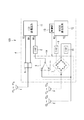
図1は、スマートメーター、スマートフォン、無線ブロードバンドルーター等に搭載可能な無線通信装置100の回路図である。このような無線通信装置100はアンテナも含めて、例えば一つの基板上にモジュール化することができる。この無線通信装置100は、第1の無線通信機能としてLTE、及び、第2の無線通信機能として920MHz帯無線(以下、RF920という。)を搭載している。
<< Circuit configuration of wireless communication device >>
FIG. 1 is a circuit diagram of a
図において、第1アンテナ1、第2アンテナ2、及び、第3アンテナ3は、基板4上で互いに必要な距離をおいて、配置されている。基板4には、共用器5、2つのアンテナスイッチ6,7、3つのフィルタ8,9,10、LTE通信回路11(第1通信回路)、RF920通信回路12(第2通信回路)、及び、制御部13が設けられている。2つのアンテナスイッチ6,7は、切替回路14を構成している。また、切替回路14を制御する制御部13が設けられている。この制御部13は、RF920通信回路12に内蔵されるか又は付随して設けられる。
In the figure, the first antenna 1, the
LTE通信回路11の送信ポートTX及び、受信ポートRX1は、共用器5を介して第1アンテナ1と接続されている。これにより、LTE通信回路11は、第1アンテナ1により送受信を行うことができる。また、LTE通信回路11の他の受信ポートRX2は、フィルタ8及びアンテナスイッチ6を介して第2アンテナ2及び第3アンテナ3のいずれか一方と接続される。
The transmission port TX and the reception port RX 1 of the
RF920通信回路12の受信ポートRXは、フィルタ9及びアンテナスイッチ7を介して、第2アンテナ2及び第3アンテナ3のいずれか一方と接続される。同様に、RF920通信回路12の送信ポートTXは、フィルタ10及びアンテナスイッチ7を介して、第2アンテナ2及び第3アンテナ3のいずれか一方と接続される。アンテナスイッチ7は、図示のようなブリッジ状に接続された4つの開閉可能接点を有している。
The reception port RX of the
《周波数帯域の例》
第1アンテナ1は、LTE用で、主として周波数帯域f1L〜f1Hの電波の送受信を行う。第2アンテナ2及び第3アンテナ3は、主として周波数帯域f2L〜f2Hの電波の送受信を行う。
図2は、LTE及びRF920が使用する周波数帯域(数値の単位は[MHz])と、各アンテナが送受信する周波数帯域の範囲を示す図である。ここでは、(a)及び(b)の2例を示している。
<< Example of frequency band >>
The first antenna 1 is for LTE, and mainly transmits and receives radio waves in the frequency bands f1 L to f1 H. The
FIG. 2 is a diagram illustrating a frequency band used by LTE and RF 920 (the unit of numerical values is [MHz]) and a frequency band range transmitted and received by each antenna. Here, two examples (a) and (b) are shown.
まず、(a)の例では、LTE送信に使用される周波数帯域は815〜830MHz、LTE受信に使用される周波数帯域は860〜875MHzである。RF920の送受信には915.9〜916.9MHz及び920.5〜929.7MHzの周波数帯域が使用される。
(a)の場合、第1アンテナ1の送受信可能な周波数帯域(f1L〜f1H)は、815〜875MHzである。第2アンテナ2及び第3アンテナ3の送受信可能な周波数帯域(f2L〜f2H)は、860〜929.7MHzである。
First, in the example of (a), the frequency band used for LTE transmission is 815 to 830 MHz, and the frequency band used for LTE reception is 860 to 875 MHz. The frequency bands of 915.9 to 916.9 MHz and 920.5 to 929.7 MHz are used for transmission and reception of RF920.
In the case of (a), the frequency band (f1 L to f1 H ) in which the first antenna 1 can transmit and receive is 815 to 875 MHz. The
また、(b)の例では、LTE送信に使用される周波数帯域は830〜845MHz、LTE受信に使用される周波数帯域は875〜890MHzである。RF920の送受信には915.9〜916.9MHz及び920.5〜929.7MHzの周波数帯域が使用される。
(b)の場合、第1アンテナ1の送受信可能な周波数帯域(f1L〜f1H)は、830〜890MHzである。第2アンテナ2及び第3アンテナ3の送受信可能な周波数帯域(f2L〜f2H)は、875〜929.7MHzである。
In the example of (b), the frequency band used for LTE transmission is 830 to 845 MHz, and the frequency band used for LTE reception is 875 to 890 MHz. The frequency bands of 915.9 to 916.9 MHz and 920.5 to 929.7 MHz are used for transmission and reception of RF920.
In the case of (b), the frequency band (f1 L to f1 H ) in which the first antenna 1 can transmit and receive is 830 to 890 MHz. The
図2の(a)、(b)において、第2アンテナ2及び第3アンテナ3は、RF920の周波数帯域のみならず、LTE受信の周波数帯域をカバーしている。従って、第2アンテナ2及び第3アンテナ3を用いて、LTE受信を行うことが可能となる。
2A and 2B, the
《無線通信装置の動作》
図3〜図6は、アンテナスイッチ6,7を含む切替回路14の動作を説明するための回路図である。各図は、信号経路を見やすく示すため、使用しない電路は点線で表示している。
<Operation of wireless communication device>
3 to 6 are circuit diagrams for explaining the operation of the switching
まず、図3において、アンテナスイッチ6,7は、図示のような接点接続状態すなわち、アンテナスイッチ6の接続は下側で、アンテナスイッチ7については右下の接点がオン、その他はオフであるとする。この場合、第3アンテナ3は、アンテナスイッチ6を介して、LTE通信回路11の受信ポートRX2と接続される。LTE通信回路11の他の受信ポートRX1は、第1アンテナ1から受信可能である。また、第2アンテナ2は、アンテナスイッチ7を介して、RF920通信回路12の送信ポートTXと接続される。
First, in FIG. 3, the
図3の状態において、RF920通信回路12は、第2アンテナ2から送信を行うことができる。LTE通信回路11は、2つの受信ポートRX1,RX2を用いてLTE受信を行うことができる。また、LTE通信回路11は、送信ポートTXから第1アンテナ1へ送信信号を出力することができる。
In the state of FIG. 3, the
次に、図4において、アンテナスイッチ6,7は、図示のような接点接続状態すなわち、アンテナスイッチ6の接続は上側で、アンテナスイッチ7については左下の接点がオン、その他はオフであるとする。この場合、第2アンテナ2は、アンテナスイッチ6を介して、LTE通信回路11の受信ポートRX2と接続される。LTE通信回路11の他の受信ポートRX1は、第1アンテナ1から受信可能である。また、第3アンテナ3は、アンテナスイッチ7を介して、RF920通信回路12の送信ポートTXと接続される。
Next, in FIG. 4, it is assumed that the
図4の状態において、RF920通信回路12は、第3アンテナ3から送信を行うことができる。LTE通信回路11は、2つの受信ポートRX1,RX2を用いてLTE受信を行うことができる。また、LTE通信回路11は、送信ポートTXから第1アンテナ1へ送信信号を出力することができる。
In the state of FIG. 4, the
前述のように、図3,図4のいずれの場合でも、LTE通信回路11は、2つのアンテナを用いたLTE受信を行うことができる。
また、制御部13は、図3及び図4のいずれかの状態を選択することにより、RF920送信の選択ダイバーシティを実現することができる。
また、アンテナ共用方法として図3,図4を見た場合、RF920通信回路12が送信をするとき、第2アンテナ2及び第3アンテナ3のうち、RF920通信回路12と接続されないアンテナをLTE通信回路11の受信ポートRX2に接続している。これにより、RF920通信回路12が送信をするときは、LTE通信回路11とRF920通信回路12とで第2アンテナ2及び第3アンテナ3を使い分けることになり、RF920通信回路12からLTE通信回路11への干渉を回避することができる。
As described above, in any of the cases of FIGS. 3 and 4, the
Moreover, the
3 and 4 as antenna sharing methods, when the
次に、図5において、アンテナスイッチ6,7は、図示のような接点接続状態すなわち、アンテナスイッチ6の接続は上側で、アンテナスイッチ7については右上の接点がオン、その他はオフであるとする。この場合、第2アンテナ2は、アンテナスイッチ6を介して、LTE通信回路11の受信ポートRX2と接続される。LTE通信回路11の他の受信ポートRX1は、第1アンテナ1から受信可能である。また、第2アンテナ2は、アンテナスイッチ7を介して、RF920通信回路12の受信ポートRXと接続される。
Next, in FIG. 5, it is assumed that the
図5の状態において、RF920通信回路12は、第2アンテナ2により受信を行うことができる。LTE通信回路11は、2つの受信ポートRX1,RX2を用いてLTE受信を行うことができる。また、LTE通信回路11は、送信ポートTXから第1アンテナ1へ送信信号を出力することができる。
In the state of FIG. 5, the
次に、図6において、アンテナスイッチ6,7は、図示のような接点接続状態すなわち、アンテナスイッチ6の接続は上側で、アンテナスイッチ7については左上の接点がオン、その他はオフであるとする。この場合、第2アンテナ2は、アンテナスイッチ6を介して、LTE通信回路11の受信ポートRX2と接続される。LTE通信回路11の他の受信ポートRX1は、第1アンテナ1から受信可能である。また、第3アンテナ3は、アンテナスイッチ7を介して、RF920通信回路12の受信ポートRXと接続される。
Next, in FIG. 6, it is assumed that the
図6の状態において、RF920通信回路12は、第3アンテナ3により受信を行うことができる。LTE通信回路11は、2つの受信ポートRX1,RX2を用いてLTE受信を行うことができる。また、LTE通信回路11は、送信ポートTXから第1アンテナ1へ送信信号を出力することができる。
In the state of FIG. 6, the
前述のように、図5,図6のいずれの場合でも、LTE通信回路11は、2つのアンテナを用いたLTE受信を行うことができる。
また、制御部13は、図5及び図6のいずれかの状態を選択することにより、RF920受信の選択ダイバーシティを実現することができる。
As described above, in either case of FIG. 5 or FIG. 6, the
Moreover, the
なお、図5において、アンテナスイッチ6の接続を下側にすれば、第3アンテナ3をLTE通信回路11の受信ポートRX2と接続することもできる。しかし、そうせずに図5のように接続することには以下の意義がある。
すなわち、図5,図6は、RF920通信回路12が送信をするとき以外(受信時又は送信しないとき)の状態を表している。ここで、図6の状態から図5の状態へ又はその逆への変遷を考えた場合、制御部12は、第2アンテナ2及び第3アンテナ3の一方を選択してRF920通信回路12の受信ポートRXに接続し、その後、選択が他方に変わっても、LTE通信回路11の受信ポートRX2に接続されるアンテナ(この例では第2アンテナ2)を変更せず維持している。
この場合、LTE通信回路11の受信ポートRX2に接続されるアンテナが変更されないので、LTE通信回路11は、RF920通信回路12による第2アンテナ2/第3アンテナ3の切り替えに伴う受信レベル変動を回避することができる。
In FIG. 5, the third antenna 3 can be connected to the reception port RX 2 of the
That is, FIGS. 5 and 6 show states other than when the
In this case, since the antenna connected to the reception port RX 2 of the
《まとめ》
上記のように構成された無線通信装置100では、RF920通信回路12が送信/受信を行う際、選択ダイバーシティに基づいて制御部13は切替回路14を制御し、第2アンテナ2又は第3アンテナ3を選択することができる。また、第2アンテナ及び第3アンテナのいずれか一方は、LTE通信回路11の受信ポートRX2へ接続され、LTE通信回路11は、第1アンテナ1を含む2つのアンテナから信号入力を得ることができる。こうして、2つのアンテナからの信号入力を要するLTE通信回路11と、2つのアンテナのうち一方を選択する選択ダイバーシティを実行するRF920通信回路12とを搭載する無線通信装置100でありながら、通信性能を損なうことなく、アンテナ数を4から3に削減することができる。また、アンテナ数が減ることで、コンパクトなスペース内でもアンテナ間の距離すなわちダイバーシティ効果を確保しやすくなる。
<Summary>
In the
また、第2アンテナ2及び第3アンテナ3は、LTE用の信号受信及びRF920の信号送受信に用いることができる。言い換えれば、第2アンテナ2及び第3アンテナ3は、LTE信号受信用に第1アンテナ1と共に用いることができる。すなわち、第2アンテナ2及び第3アンテナ3は、RF920用のみならず、LTE用としても用いることができ、アンテナの共用を行うことができる。
The
なお、制御部13は、RF920通信回路12に付随して設けられる(内蔵されることも含む。)。制御部13は、RF920通信回路12の選択ダイバーシティに基づいて切替回路14による接続動作を制御するので、RF920通信回路12と密接な関係にあり、従って、RF920通信回路12に付随して設けられる構成とすることが好ましい。
The
また、RF920通信回路12が送信をするとき、第2アンテナ2及び第3アンテナ3のうち、RF920通信回路12と接続されないアンテナをLTE通信回路11に接続することにより、RF920通信回路12が送信をするときは、LTE通信回路11とRF920通信回路12とで第2アンテナ2及び第3アンテナ3を使い分けることになり、RF920通信回路12からLTE通信回路11への干渉を回避することができる。
一方、RF920通信回路12が送信をするとき以外は、第2アンテナ2及び第3アンテナ3の一方を選択してRF920通信回路12に接続し、その後、選択が他方に変わっても、LTE通信回路11の受信ポートRX2に接続されるアンテナを変更せず維持することで、LTE通信回路11は、RF920通信回路12による第2アンテナ2/第3アンテナ3の切り替えに伴う受信レベル変動を回避することができる。
Further, when the
On the other hand, except when the
《その他の構成》
なお、上記実施形態における無線通信装置100は、2種類の無線通信機能を搭載するものであるが、3種類以上の無線通信機能を搭載した場合でも、同様な回路構成により、少なくとも2種類についてアンテナ数を削減することができる。これにより、異種複数の通信回路を搭載する無線通信装置において、通信性能を損なうことなく、アンテナ数を削減することができる。
<Other configuration>
Note that the
《補記》
なお、今回開示された実施の形態はすべての点で例示であって制限的なものではないと考えられるべきである。本発明の範囲は特許請求の範囲によって示され、特許請求の範囲と均等の意味及び範囲内での全ての変更が含まれることが意図される。
《Supplementary Note》
The embodiment disclosed this time should be considered as illustrative in all points and not restrictive. The scope of the present invention is defined by the terms of the claims, and is intended to include any modifications within the scope and meaning equivalent to the terms of the claims.
1 第1アンテナ
2 第2アンテナ
3 第3アンテナ
4 基板
5 共用器
6,7 アンテナスイッチ
8,9,10 フィルタ
11 LTE通信回路
12 RF920通信回路
13 制御部
14 切替回路
100 無線通信装置
TX 送信ポート
RX,RX1,RX2 受信ポート
DESCRIPTION OF SYMBOLS 1
Claims (5)
第1アンテナと、
第2アンテナと、
第3アンテナと、
第1の無線通信機能を有し、送信時には前記第1アンテナと接続され、受信時には前記第1アンテナを含む2つのアンテナからの信号入力を要する第1通信回路と、
第2の無線通信機能を有し、2つのアンテナのうち一方を選択する選択ダイバーシティを実行する第2通信回路と、
前記第2アンテナ及び前記第3アンテナを択一的に前記第1通信回路の受信ポートへ接続するとともに、前記第2アンテナ及び前記第3アンテナのいずれか一方を、前記第2通信回路の送信ポート及び受信ポートのいずれか一方と接続する切替回路と、
前記第2通信回路の前記選択ダイバーシティに基づいて、前記切替回路による接続動作を制御する制御部と、
を備えている無線通信装置。 A wireless communication device equipped with at least two types of wireless communication functions,
A first antenna;
A second antenna;
A third antenna;
A first communication circuit which has a first wireless communication function, is connected to the first antenna at the time of transmission, and requires signal input from two antennas including the first antenna at the time of reception;
A second communication circuit having a second wireless communication function and executing selection diversity for selecting one of the two antennas;
The second antenna and the third antenna are alternatively connected to the reception port of the first communication circuit, and one of the second antenna and the third antenna is connected to the transmission port of the second communication circuit. And a switching circuit connected to any one of the receiving port,
A control unit for controlling a connection operation by the switching circuit based on the selection diversity of the second communication circuit;
A wireless communication device comprising:
前記第2通信回路は、選択ダイバーシティに基づいて、前記第2アンテナ及び前記第3アンテナのいずれか一方を選択し、
前記第2アンテナ及び前記第3アンテナのいずれか一方を前記第1通信回路の受信ポートへ接続する、
アンテナ共用方法。 A first antenna, a second antenna, a third antenna, and a first wireless communication function, are connected to the first antenna at the time of transmission, and input signals from two antennas including the first antenna at the time of reception In a wireless communication apparatus comprising a first communication circuit that requires a second communication circuit and a second communication circuit that has a second wireless communication function and executes selection diversity for selecting one of the two antennas, each antenna and each communication An antenna sharing method using a switching circuit in which a connection mode for connecting a circuit is variable,
The second communication circuit selects one of the second antenna and the third antenna based on selection diversity,
Connecting one of the second antenna and the third antenna to a reception port of the first communication circuit;
Antenna sharing method.
前記第2通信回路が送信をするとき以外は、前記第2アンテナ及び前記第3アンテナの一方を選択して前記第2通信回路の受信ポートに接続し、その後、選択が他方に変わっても、前記第1通信回路の受信ポートに接続されるアンテナを変更せず維持する、請求項4に記載のアンテナ共用方法。 When the second communication circuit transmits, an antenna that is not connected to the second communication circuit is connected to the reception port of the first communication circuit, among the second antenna and the third antenna,
Except when the second communication circuit transmits, even if one of the second antenna and the third antenna is selected and connected to the reception port of the second communication circuit, and then the selection changes to the other, The antenna sharing method according to claim 4, wherein the antenna connected to the reception port of the first communication circuit is maintained without being changed.
Priority Applications (1)
| Application Number | Priority Date | Filing Date | Title |
|---|---|---|---|
| JP2014234470A JP2016100676A (en) | 2014-11-19 | 2014-11-19 | Radio communication device and antenna sharing method |
Applications Claiming Priority (1)
| Application Number | Priority Date | Filing Date | Title |
|---|---|---|---|
| JP2014234470A JP2016100676A (en) | 2014-11-19 | 2014-11-19 | Radio communication device and antenna sharing method |
Publications (1)
| Publication Number | Publication Date |
|---|---|
| JP2016100676A true JP2016100676A (en) | 2016-05-30 |
Family
ID=56076407
Family Applications (1)
| Application Number | Title | Priority Date | Filing Date |
|---|---|---|---|
| JP2014234470A Pending JP2016100676A (en) | 2014-11-19 | 2014-11-19 | Radio communication device and antenna sharing method |
Country Status (1)
| Country | Link |
|---|---|
| JP (1) | JP2016100676A (en) |
Cited By (3)
| Publication number | Priority date | Publication date | Assignee | Title |
|---|---|---|---|---|
| CN108259046A (en) * | 2018-01-08 | 2018-07-06 | 维沃移动通信有限公司 | A kind of antenna system and mobile terminal |
| CN112564744A (en) * | 2020-11-27 | 2021-03-26 | 天津七一二通信广播股份有限公司 | Transmission bandwidth synthesis circuit based on LTE communication module and implementation method |
| CN112910495A (en) * | 2019-11-19 | 2021-06-04 | RealMe重庆移动通信有限公司 | Communication module selection method and device based on terminal equipment |
-
2014
- 2014-11-19 JP JP2014234470A patent/JP2016100676A/en active Pending
Cited By (5)
| Publication number | Priority date | Publication date | Assignee | Title |
|---|---|---|---|---|
| CN108259046A (en) * | 2018-01-08 | 2018-07-06 | 维沃移动通信有限公司 | A kind of antenna system and mobile terminal |
| CN108259046B (en) * | 2018-01-08 | 2020-02-21 | 维沃移动通信有限公司 | Antenna system and mobile terminal |
| CN112910495A (en) * | 2019-11-19 | 2021-06-04 | RealMe重庆移动通信有限公司 | Communication module selection method and device based on terminal equipment |
| CN112910495B (en) * | 2019-11-19 | 2022-08-16 | RealMe重庆移动通信有限公司 | Communication module selection method and device based on terminal equipment |
| CN112564744A (en) * | 2020-11-27 | 2021-03-26 | 天津七一二通信广播股份有限公司 | Transmission bandwidth synthesis circuit based on LTE communication module and implementation method |
Similar Documents
| Publication | Publication Date | Title |
|---|---|---|
| JP6955103B2 (en) | Multi-way switch, radio frequency system and wireless communication device | |
| JP7038214B2 (en) | Multi-way switch, radio frequency system and wireless communication device | |
| JP7182634B2 (en) | Multiway switch, radio frequency system and wireless communication device | |
| CN108988904B (en) | Radio frequency system, antenna switching control method and related product | |
| US9444609B2 (en) | RF front end arrangement and method for sharing first and second antennas by different frequency bands | |
| JP7065961B2 (en) | Multi-way switch, radio frequency system and wireless communication device | |
| JP7038216B2 (en) | Multi-way switch, radio frequency system and wireless communication device | |
| JP7038212B2 (en) | Multi-way switch, radio frequency system and wireless communication device | |
| CN108880602B (en) | Multi-way selector switch and related products | |
| JP2021507638A (en) | Multi-way switch, radio frequency system and wireless communication device | |
| CN106209199A (en) | For increasing the method for range for wireless communication, equipment and system | |
| CN108923790A (en) | Multidiameter option switch, radio frequency system and wireless telecom equipment | |
| JP7078738B2 (en) | Multi-way switches, radio frequency systems, and wireless communication devices | |
| EP3540969A1 (en) | Multiway switch, radio frequency system, and communication device | |
| CN108900201B (en) | Multi-way selector switch, radio frequency system and electronic equipment | |
| EP2580811B1 (en) | A node in a communication system with switchable antenna functions | |
| CN108923792B (en) | Multi-way selector switch and related products | |
| CN109039345A (en) | Multidiameter option switch and Related product | |
| CN108964675A (en) | Multidiameter option switch and Related product | |
| CN105846866A (en) | Bluetooth transparent relay | |
| JP2016100676A (en) | Radio communication device and antenna sharing method | |
| US10374652B2 (en) | Antenna switching in a communication circuit | |
| JP2016127487A (en) | Radio communication equipment and antenna sharing method | |
| CN113489503B (en) | Radio frequency architecture and electronic device | |
| CN113949429A (en) | Signal processing device and electronic equipment |