JP2016098794A - Internal combustion engine control device - Google Patents
Internal combustion engine control device Download PDFInfo
- Publication number
- JP2016098794A JP2016098794A JP2014238943A JP2014238943A JP2016098794A JP 2016098794 A JP2016098794 A JP 2016098794A JP 2014238943 A JP2014238943 A JP 2014238943A JP 2014238943 A JP2014238943 A JP 2014238943A JP 2016098794 A JP2016098794 A JP 2016098794A
- Authority
- JP
- Japan
- Prior art keywords
- combustion
- fuel
- injection
- ignition
- main
- Prior art date
- Legal status (The legal status is an assumption and is not a legal conclusion. Google has not performed a legal analysis and makes no representation as to the accuracy of the status listed.)
- Pending
Links
Images


Abstract
Description
本発明は、内燃機関の制御装置に関する。 The present invention relates to a control device for an internal combustion engine.
燃焼室内の圧縮空気に対して燃料を直接噴射して該燃料を自着火させ拡散燃焼させる燃焼形態である、いわゆるディーゼル燃焼は、火花点火による燃焼と比べて熱効率が高い。近年、このようなディーゼル燃焼の利点をガソリンエンジンにおいても享受すべく、ガソリンの自着火および拡散燃焼による燃焼を成立させるための技術が開発されている。 So-called diesel combustion, which is a combustion mode in which fuel is directly injected into compressed air in the combustion chamber and self-ignited and diffusely combusted, has higher thermal efficiency than combustion by spark ignition. In recent years, in order to enjoy such advantages of diesel combustion even in a gasoline engine, a technology for establishing combustion by self-ignition and diffusion combustion of gasoline has been developed.
例えば、特許文献1に開示の技術では、先ず、筒内噴射弁によって圧縮行程前半に第1の燃料噴射を行うことで燃焼室内全域にほぼ均質な混合気を形成する。そして、第1の燃料噴射によって形成された混合気に対し火花点火を行う。その後に第2の燃料噴射を行って噴射された燃料を燃焼させ、さらに、この燃焼による燃焼室内の温度および圧力上昇により残りの燃料を自着火させる。
For example, in the technique disclosed in
また、特許文献2には、自着火温度が比較的高い天然ガス等を燃料としてディーゼル燃焼を実現させるための技術が開示されている。この特許文献2に開示の技術では、先ず、燃焼室内の所定の火花点火領域において圧縮行程の初期又は中期に燃料噴射を行うことで火花点火可能な混合気を形成する。そして、この火花点火領域に形成された混合気に対して圧縮行程上死点直前の時期に点火することで火花点火燃焼を行う。これによって、燃焼室内が天然ガスの自着火が可能な高温且つ高圧の状態となる。その後、高温高圧状態の燃焼室内に直接燃料を噴射して該燃料をディーゼル燃焼させる。
また、特許文献3には、吸気ポートに燃料を噴射するポート噴射弁と、気筒内に燃料を噴射する筒内噴射弁とを有し、気筒内に供給された燃料と空気との混合気を自着火によって燃焼させる内燃機関において、筒内噴射弁からの燃料噴射量を総燃料噴射量の3〜11%に設定する技術が開示されている。 Further, Patent Document 3 includes a port injection valve that injects fuel into an intake port and an in-cylinder injection valve that injects fuel into a cylinder. A mixture of fuel and air supplied into the cylinder is disclosed in Patent Document 3. In an internal combustion engine that burns by self-ignition, a technique for setting the fuel injection amount from the in-cylinder injection valve to 3 to 11% of the total fuel injection amount is disclosed.
ガソリンのように自着火温度が比較的高い燃料を用いてディーゼル燃焼を行う場合、機関負荷の上昇に従って燃焼室内への燃料噴射量が増加すると、局所的に燃料に対する酸素の量が不足した状態が生じ、その結果、スモークの発生量が増加する虞がある。本発明は、このような問題に鑑みてなされたものであって、自着火温度が比較的高い燃料を使用する内燃機関において、スモークの発生量を抑制しつつディーゼル燃焼を実現することを目的とする。 When diesel combustion is performed using a fuel having a relatively high self-ignition temperature such as gasoline, if the amount of fuel injected into the combustion chamber increases as the engine load increases, the amount of oxygen relative to the fuel may be locally insufficient. As a result, the amount of smoke generated may increase. The present invention has been made in view of such a problem, and an object of the present invention is to realize diesel combustion while suppressing the amount of smoke generated in an internal combustion engine using a fuel having a relatively high self-ignition temperature. To do.
第一の発明では、圧縮工程中に火花点火によるプレ燃焼が行われる。その後、圧縮行程上死点前に、筒内噴射弁によるメイン噴射が実行される。これにより、プレ燃焼によって生じた火炎を起点として、メイン噴射によって噴射された燃料の燃焼が開始され、さらに
燃料の自着火および拡散燃焼が生じる。そして、本発明では、内燃機関の機関負荷が所定負荷以下の運転領域においては、プレ燃焼のための燃料噴射を筒内噴射弁によるプレ噴射によって行う。そして、内燃機関の機関負荷が所定負荷より高い運転領域においては、プレ燃焼のための燃料噴射を、ポート噴射弁によるポート噴射および筒内噴射弁によるプレ噴射によって行う。
In the first invention, pre-combustion by spark ignition is performed during the compression process. Thereafter, main injection by the in-cylinder injection valve is executed before the top dead center of the compression stroke. Thereby, starting from the flame generated by the pre-combustion, combustion of the fuel injected by the main injection is started, and further, self-ignition and diffusion combustion of the fuel occur. In the present invention, fuel injection for pre-combustion is performed by pre-injection using the in-cylinder injection valve in an operation region where the engine load of the internal combustion engine is equal to or less than a predetermined load. In an operation region where the engine load of the internal combustion engine is higher than a predetermined load, fuel injection for pre-combustion is performed by port injection by the port injection valve and pre-injection by the in-cylinder injection valve.
なお、本発明において使用される、「プレ」、「メイン」の用語は、各燃料噴射または各燃焼の時間的な前後関係を表す表現にすぎず、以下に示す技術的意義を有するもの以外に限定解釈されるべきではない。また、以下においては、筒内噴射弁によるプレ噴射によって噴射された燃料を「プレ噴射燃料」と称し、筒内噴射弁によるメイン噴射によって噴射された燃料を「メイン燃料噴射」と称し、ポート噴射弁によるポート噴射によって噴射された燃料を「ポート噴射燃料」と称する場合もある。 It should be noted that the terms “pre” and “main” used in the present invention are merely expressions representing the temporal context of each fuel injection or each combustion, other than those having the technical significance shown below. It should not be limited. In the following, the fuel injected by the pre-injection by the in-cylinder injection valve is referred to as “pre-injection fuel”, the fuel injected by the main injection by the in-cylinder injection valve is referred to as “main fuel injection”, and the port injection The fuel injected by the port injection by the valve may be referred to as “port injection fuel”.
より詳しくは、第一の発明に係る内燃機関の制御装置は、内燃機関の燃焼室内に燃料を噴射可能な筒内噴射弁と、内燃機関の吸気ポート内に燃料を噴射可能なポート噴射弁と、前記筒内噴射弁から噴射された噴霧が点火可能領域を通過し該噴霧に直接に点火可能となるように、該筒内噴射弁に対する相対位置が決定された点火装置と、内燃機関の機関負荷が所定負荷以下の運転領域において、圧縮行程中に前記筒内噴射弁によってプレ噴射を実行するとともに該プレ噴射によって形成されるプレ噴霧に対し前記点火装置によって点火を行うことで該プレ噴射によって噴射された燃料の一部を燃焼させて第1プレ燃焼を行う第1プレ燃焼部と、内燃機関の機関負荷が前記所定負荷より高い運転領域において、排気行程または吸気行程中に前記ポート噴射弁によってポート噴射を実行することで混合気を形成させるとともに、圧縮行程中に前記筒内噴射弁によってプレ噴射を実行することで該混合気中にプレ噴霧を形成させ、さらに、該プレ噴霧に対し前記点火装置によって点火を行うことで該第プレ噴射によって噴射された燃料の一部および該ポート噴射によって噴射された燃料の一部を燃焼させて第2プレ燃焼を行う第2プレ燃焼部と、前記第1プレ燃焼または前記第2プレ燃焼の発生後であり且つ圧縮行程上死点前の時期であって、前記第1プレ燃焼または前記第2プレ燃焼によって生じた火炎を起点として噴射燃料の燃焼が開始されるように設定されたメイン噴射時期に前記筒内噴射弁によるメイン噴射の実行を開始することで、燃料の自着火を発生させるとともに少なくとも該メイン噴射によって噴射された燃料の一部を拡散燃焼させてメイン燃焼を行うメイン燃焼部と、を備える。 More specifically, the control device for an internal combustion engine according to the first aspect of the invention includes a cylinder injection valve capable of injecting fuel into a combustion chamber of the internal combustion engine, and a port injection valve capable of injecting fuel into an intake port of the internal combustion engine. An ignition device whose relative position with respect to the in-cylinder injection valve is determined so that the spray injected from the in-cylinder injection valve passes through the ignitable region and can be directly ignited, and an engine of the internal combustion engine In an operation region where the load is equal to or less than a predetermined load, pre-injection is executed by the in-cylinder injection valve during the compression stroke, and the pre-spray formed by the pre-injection is ignited by the ignition device. A first pre-combustion unit that performs a first pre-combustion by burning a part of the injected fuel, and an operation range in which the engine load of the internal combustion engine is higher than the predetermined load, during the exhaust stroke or the intake stroke, A gas mixture is formed by performing port injection with a fuel injection valve, and a pre-spray is formed in the gas mixture by performing pre-injection with the in-cylinder injection valve during the compression stroke. Second pre-combustion in which second pre-combustion is performed by burning part of the fuel injected by the first pre-injection and part of the fuel injected by the port injection by igniting the spray with the ignition device And a flame after the occurrence of the first pre-combustion or the second pre-combustion and before the compression stroke top dead center, starting from a flame generated by the first pre-combustion or the second pre-combustion By starting the execution of the main injection by the in-cylinder injection valve at the main injection timing set to start the combustion of the injected fuel, the fuel self-ignition is generated and at least The part of the fuel injected by the main injection is diffusion combustion and a main combustion section which performs main combustion.
本発明では、内燃機関の機関負荷が所定負荷以下の運転領域では、先ず、圧縮行程中における筒内噴射弁によるプレ噴射と、プレ噴射燃料により形成されたプレ噴霧への点火装置による点火とによって第1プレ燃焼が行われる。その後、圧縮行程上死点前にメイン噴射の実行が開始されることで、燃料の自着火および拡散燃焼(メイン燃焼)が生じる。なお、メイン噴射は、圧縮行程上死点前に実行が開始される噴射であるが、圧縮行程上死点以降までその実行が継続されてもよい。 In the present invention, in an operating region where the engine load of the internal combustion engine is equal to or less than a predetermined load, first, pre-injection by the in-cylinder injection valve during the compression stroke and ignition by the ignition device to the pre-spray formed by the pre-injected fuel are performed. First pre-combustion is performed. Thereafter, the execution of the main injection is started before the top dead center of the compression stroke, whereby fuel self-ignition and diffusion combustion (main combustion) occur. The main injection is an injection that starts executing before the compression stroke top dead center. However, the execution may continue until the compression stroke top dead center.
ここで、プレ噴射、点火、およびメイン噴射の時期は、第1プレ燃焼によって生じた火炎を起点としてメイン噴射燃料の燃焼が開始されるように設定されている。そして、メイン噴射燃料の燃焼が開始されると、燃焼室内の温度および圧力が上昇することで、燃料の自着火が発生し、さらには少なくともメイン噴射燃料の一部が拡散燃焼することとなる。また、プレ噴射燃料のうち、点火装置による点火によって燃焼する燃料は一部であって、その多くは、メイン噴射の実行開始後に自着火または拡散燃焼によって燃焼する。したがって、プレ噴射燃料およびメイン噴射燃料のいずれも内燃機関の出力に寄与することとなる。そのため、熱効率の高いディーゼル燃焼を実現することが可能となる。 Here, the timings of the pre-injection, ignition, and main injection are set so that the combustion of the main injection fuel is started from the flame generated by the first pre-combustion. When the combustion of the main injected fuel is started, the temperature and pressure in the combustion chamber rise, so that fuel self-ignition occurs, and at least a part of the main injected fuel is diffusely burned. Further, some of the pre-injected fuel is combusted by ignition by the ignition device, and most of the fuel is combusted by self-ignition or diffusion combustion after the start of the main injection. Therefore, both the pre-injected fuel and the main injected fuel contribute to the output of the internal combustion engine. Therefore, it is possible to realize diesel combustion with high thermal efficiency.
ここで、内燃機関の機関負荷が上昇すると、燃焼室内に供給する燃料を増量する必要がある。しかしながら、メイン噴射は、圧縮行程上死点近傍の燃焼室内の圧力が高い時に行
われるため、筒内噴射弁から噴射された燃料噴霧のペネトレーションが小さくなる。つまり、メイン噴射によって噴射された燃料噴霧は広範囲に広がり難い。そのため、メイン噴射燃料量が過剰に増量されると、メイン噴射燃料の噴霧の周囲に存在する酸素、即ち、メイン噴射燃料の燃焼に供される酸素の量が燃料に対して不足した状態となり、その結果、スモークの発生量が増加する虞がある。
Here, when the engine load of the internal combustion engine increases, it is necessary to increase the amount of fuel supplied into the combustion chamber. However, since the main injection is performed when the pressure in the combustion chamber near the top dead center of the compression stroke is high, the penetration of the fuel spray injected from the in-cylinder injection valve is reduced. That is, the fuel spray injected by the main injection is difficult to spread over a wide range. Therefore, if the amount of the main injection fuel is excessively increased, the oxygen present around the spray of the main injection fuel, that is, the amount of oxygen provided for the combustion of the main injection fuel becomes insufficient with respect to the fuel, As a result, the amount of smoke generated may increase.
また、上記のように、プレ噴射燃料の多くは点火装置による点火では燃焼せずに燃え残り、メイン噴射が実行される時にも未燃の状態で燃焼室内に存在している。そのため、メイン噴射燃料に代えて又はメイン噴射燃料とともにプレ噴射燃料が増量されると、メイン噴射が実行される時に燃焼室内に存在しているプレ噴射燃料の燃え残り量が増加することになる。しかしながら、プレ噴射燃料が過剰に増量されると、メイン噴射が実行された時に、燃焼室内においてプレ噴射燃料の燃え残りとメイン噴射燃料とが重なり合った部分では、燃料濃度が過剰に高くなる場合がある。この場合、当該部分の周囲に存在する酸素、即ち、当該部分に存在する燃料の燃焼に供される酸素の量が燃料に対して不足した状態となり、その結果、スモークの発生量が増加する虞がある。 In addition, as described above, most of the pre-injected fuel remains unburned without being burned by ignition by the ignition device, and remains in the combustion chamber in an unburned state when main injection is executed. Therefore, if the amount of pre-injected fuel is increased instead of or together with the main injected fuel, the remaining amount of pre-injected fuel existing in the combustion chamber increases when the main injection is executed. However, if the pre-injected fuel is excessively increased, when the main injection is executed, the fuel concentration may become excessively high in a portion where the unburned residue of the pre-injected fuel and the main injected fuel overlap in the combustion chamber. is there. In this case, the amount of oxygen present around the portion, that is, the amount of oxygen used for combustion of the fuel present in the portion is insufficient with respect to the fuel, and as a result, the amount of smoke generated may increase. There is.
つまり、プレ噴射およびメイン噴射のいずれにおいても、その噴射量が過剰に増量されると、スモークの発生量が増加する虞がある。そこで、本発明では、内燃機関の機関負荷が所定負荷より高い運転領域では、プレ噴射のみを用いた第1プレ燃焼に代えて、ポート噴射弁によるポート噴射と筒内噴射弁によるプレ噴射とを併用する第2プレ燃焼を行う。ここでの所定負荷とは、一燃焼サイクル中における総燃料噴射量が比較的多く必要となる機関負荷であって、プレ噴射燃料量またはメイン噴射燃料量の増量に伴うスモークの発生量が過剰に増加することが懸念される機関負荷の閾値である。 That is, in both the pre-injection and the main injection, if the injection amount is excessively increased, the amount of smoke generated may increase. Therefore, in the present invention, in the operation region where the engine load of the internal combustion engine is higher than the predetermined load, instead of the first pre-combustion using only pre-injection, port injection by the port injection valve and pre-injection by the in-cylinder injection valve are performed. Second pre-combustion to be used together is performed. Here, the predetermined load is an engine load that requires a relatively large total fuel injection amount during one combustion cycle, and an excessive amount of smoke generated due to an increase in the pre-injection fuel amount or the main injection fuel amount. This is the threshold of the engine load that is expected to increase.
第2プレ燃焼を行う際には、排気行程または吸気行程中にポート噴射弁によってポート噴射を実行する。つまり、ポート噴射は、吸気弁が閉弁状態の時に実行されてもよく、また、吸気弁が開弁状態の時に実行されてもよい。ポート噴射が実行されると、ポート噴射燃料によって、燃焼室内に混合気が形成されることになる。次に、圧縮行程中に筒内噴射弁によってプレ噴射を実行する。これにより、ポート噴射燃料によって形成された混合気中に、プレ噴射燃料によってプレ噴霧が形成されることになる。そして、このプレ噴霧に対し点火装置によって点火が行われる。この点火によりプレ噴射燃料の一部およびポート噴射燃料の一部が燃焼する。ここで、第2プレ燃焼では、第1プレ燃焼と同様、メイン燃料の燃焼のための火種となる火炎が形成される程度の燃焼が行われればよい。そのため、本発明では、ポート噴射燃料によって形成される混合気の空燃比が、点火装置によるプレ噴霧への点火によって生じる火炎の伝播により燃焼するポート噴射燃料がポート噴射燃料量のうちの一部に抑えられる空燃比となるように、ポート噴射燃料量が設定されている。 When performing the second pre-combustion, port injection is performed by the port injection valve during the exhaust stroke or the intake stroke. That is, the port injection may be executed when the intake valve is closed, or may be executed when the intake valve is open. When the port injection is executed, an air-fuel mixture is formed in the combustion chamber by the port injection fuel. Next, pre-injection is executed by the in-cylinder injection valve during the compression stroke. As a result, a pre-spray is formed by the pre-injected fuel in the air-fuel mixture formed by the port injected fuel. The pre-spray is ignited by an ignition device. By this ignition, a part of the pre-injected fuel and a part of the port-injected fuel are combusted. Here, in the second pre-combustion, similarly to the first pre-combustion, it is sufficient to perform combustion to such an extent that a flame that serves as a fire type for main fuel combustion is formed. Therefore, in the present invention, the air-fuel ratio of the air-fuel mixture formed by the port-injected fuel is such that the port-injected fuel combusted by the propagation of flame generated by the ignition to the pre-spray by the ignition device is part of the port-injected fuel amount. The port injection fuel amount is set so that the air-fuel ratio can be suppressed.
点火装置による点火によって生じた火炎伝播では燃焼せずに燃え残ったポート噴射燃料は、プレ噴射の燃え残りとともにメイン燃料噴射後の自着火または拡散燃焼によって燃焼する。これにより、メイン噴射燃料およびプレ噴射燃料に加えポート噴射燃料も内燃機関の出力に寄与することとなる。そのため、第1プレ燃焼に代えて第2プレ燃焼を行った場合でも、熱効率の高いディーゼル燃焼を実現することができる。 The port-injected fuel that remains unburned without being burned by the flame propagation caused by ignition by the ignition device is burned by the self-ignition after the main fuel injection or diffusion combustion together with the unburned residue of the pre-injection. Thereby, in addition to the main injection fuel and the pre-injection fuel, the port injection fuel also contributes to the output of the internal combustion engine. Therefore, even when the second pre-combustion is performed instead of the first pre-combustion, diesel combustion with high thermal efficiency can be realized.
また、本発明に係る第2プレ燃焼においては、プレ噴射に加えてポート噴射を用いるために、プレ噴射のみを用いる第1プレ燃焼に比べて、プレ噴射燃料を減量することができる。さらに、燃焼室内に混合気を形成するポート噴射燃料は、メイン噴射燃料よりも燃焼室内においてより広範囲に分布している。そのため、メイン燃焼時において、ポート噴射燃料の燃焼に必要な酸素を十分に確保することができる。また、該ポート噴射燃料は、プレ噴射燃料の燃え残りよりも、燃焼室内においてさらに広範囲に分布することなる。そのため、メイン噴射燃料とポート噴射燃料とが重なった部分の燃料濃度は、メイン噴射燃料
とプレ噴射燃料(燃え残り)とが重なった部分の燃料濃度より低くなる。したがって、ポート噴射燃料は、メイン噴射燃料およびプレ噴射燃料のいずれと比べてもスモークの発生原因となり難い。
Further, in the second pre-combustion according to the present invention, since the port injection is used in addition to the pre-injection, the pre-injected fuel can be reduced as compared with the first pre-combustion using only the pre-injection. Furthermore, the port injection fuel that forms the air-fuel mixture in the combustion chamber is more widely distributed in the combustion chamber than the main injection fuel. Therefore, at the time of main combustion, it is possible to sufficiently secure oxygen necessary for the combustion of the port injection fuel. Further, the port-injected fuel is distributed in a wider range in the combustion chamber than the unburned residue of the pre-injected fuel. Therefore, the fuel concentration in the portion where the main injection fuel and the port injection fuel overlap is lower than the fuel concentration in the portion where the main injection fuel and the pre-injection fuel (unburned fuel) overlap. Therefore, the port-injected fuel is unlikely to cause smoke as compared with either the main-injected fuel or the pre-injected fuel.
そのため、機関負荷が所定負荷よりも高い運転領域、すなわち、一燃焼サイクル中の総燃料噴射量が比較的多くなる運転領域では、第1プレ燃焼に代えて第2プレ燃焼を行うことで、スモークの発生量を抑制しつつディーゼル燃焼を実現することができる。 For this reason, in the operation region where the engine load is higher than the predetermined load, that is, the operation region where the total fuel injection amount during one combustion cycle is relatively large, the second pre-combustion is performed instead of the first pre-combustion, so that the smoke Diesel combustion can be realized while suppressing the generation amount of NO.
第二の発明では、プレ燃焼のための燃料噴射を、ポート噴射弁によるポート噴射のみによって行う。 In the second invention, fuel injection for pre-combustion is performed only by port injection by the port injection valve.
より詳細には、第二の発明に係る内燃機関の制御装置は、内燃機関の燃焼室内に燃料を噴射可能な筒内噴射弁と、内燃機関の吸気ポート内に燃料を噴射可能なポート噴射弁と、前記筒内噴射弁から噴射された噴霧が点火可能領域を通過し該噴霧に直接に点火可能となるように、該筒内噴射弁に対する相対位置が決定された点火装置と、排気行程または吸気行程中に前記ポート噴射弁によってポート噴射を実行することで混合気を形成させるとともに、圧縮行程中に燃焼室内において該混合気に対し前記点火装置によって点火を行うことで該ポート噴射によって噴射された燃料の一部を燃焼させてプレ燃焼を行うプレ燃焼部と、前記プレ燃焼の発生後であり且つ圧縮行程上死点前の時期であって、前記プレ燃焼によって生じた火炎を起点として噴射燃料の燃焼が開始されるように設定されたメイン噴射時期に前記筒内噴射弁によるメイン噴射の実行を開始することで、燃料の自着火を発生させるとともに少なくとも該メイン噴射によって噴射された燃料の一部を拡散燃焼させてメイン燃焼を行うメイン燃焼部と、を備える。 More specifically, the control device for an internal combustion engine according to the second invention includes a cylinder injection valve capable of injecting fuel into a combustion chamber of the internal combustion engine, and a port injection valve capable of injecting fuel into an intake port of the internal combustion engine. An ignition device whose relative position to the in-cylinder injection valve is determined so that the spray injected from the in-cylinder injection valve passes through the ignitable region and can be directly ignited, and an exhaust stroke or An air-fuel mixture is formed by executing port injection by the port injection valve during the intake stroke, and is injected by the port injection by igniting the air-fuel mixture by the ignition device in the combustion chamber during the compression stroke. A pre-combustion section that performs pre-combustion by burning a part of the fuel, and a timing after the occurrence of the pre-combustion and before the top dead center of the compression stroke, starting from the flame generated by the pre-combustion By starting execution of main injection by the in-cylinder injection valve at the main injection timing set so that combustion of the injected fuel is started, fuel self-ignition is generated and at least the fuel injected by the main injection A main combustion section for performing main combustion by diffusing and burning a part of the main combustion section.
本発明では、プレ燃焼を行う際に、排気行程または吸気行程中にポート噴射弁によってポート噴射を実行することで燃焼室内に混合気を形成する。このとき、ポート噴射は、吸気弁が閉弁状態の時に実行されてもよく、また、吸気弁が開弁状態の時に実行されてもよい。そして、ポート噴射燃料によって燃焼室内に形成された混合気に対して点火装置によって点火を行うことでプレ燃焼が行われる。なお、このプレ燃焼においても、メイン燃料の燃焼のための火種となる火炎が形成される程度の燃焼が行われればよい。そのため、ポート噴射燃料によって形成される混合気の空燃比が、点火装置による点火によって燃料が着火することで火炎は生じるが、該火炎の伝播ではポート噴射燃料の一部のみが燃焼する空燃比となるように、ポート噴射燃料量が設定されている。 In the present invention, when pre-combustion is performed, an air-fuel mixture is formed in the combustion chamber by performing port injection by the port injection valve during the exhaust stroke or the intake stroke. At this time, the port injection may be executed when the intake valve is closed, or may be executed when the intake valve is open. And precombustion is performed by igniting with the ignition device with respect to the air-fuel | gaseous mixture formed in the combustion chamber with the port injection fuel. In this pre-combustion as well, it is only necessary to perform combustion to such an extent that a flame as a fire type for main fuel combustion is formed. Therefore, the air-fuel ratio of the air-fuel mixture formed by the port-injected fuel is such that a flame is generated when the fuel is ignited by ignition by the igniter, but in the propagation of the flame, only a part of the port-injected fuel burns. Thus, the port injection fuel amount is set.
点火装置による点火によって生じた火炎伝播では燃焼せずに燃え残ったポート噴射燃料は、プレ噴射の燃え残りとともにメイン燃料噴射後の自着火または拡散燃焼によって燃焼する。これにより、メイン噴射燃料に加えポート噴射燃料も内燃機関の出力に寄与することとなる。そのため、本発明に係るプレ燃焼を行った場合でも、熱効率の高いディーゼル燃焼を実現することができる。また、上述したように、ポート噴射燃料は、メイン噴射燃料のみならず、プレ噴射燃料と比べてもスモークの発生原因となり難い。 The port-injected fuel that remains unburned without being burned by the flame propagation caused by ignition by the ignition device is burned by the self-ignition after the main fuel injection or diffusion combustion together with the unburned residue of the pre-injection. Thereby, in addition to the main injected fuel, the port injected fuel also contributes to the output of the internal combustion engine. Therefore, even when pre-combustion according to the present invention is performed, diesel combustion with high thermal efficiency can be realized. Further, as described above, the port injection fuel is less likely to cause smoke than the main injection fuel as well as the pre-injection fuel.
したがって、本発明によれば、ポート噴射のみを用いてプレ燃焼を行うことで、スモークの発生量を抑制しつつディーゼル燃焼を実現することができる。 Therefore, according to the present invention, by performing pre-combustion using only port injection, diesel combustion can be realized while suppressing the amount of smoke generated.
また、本発明においては、前記プレ燃焼部を第2プレ燃焼部とし、前記プレ燃焼を第2プレ燃焼としてもよい。そして、本発明に係る内燃機関の制御装置は、圧縮行程中に前記筒内噴射弁によってプレ噴射を実行するとともに該プレ噴射によって形成されるプレ噴霧に対し点火装置によって点火を行うことで該プレ噴射によって噴射された燃料の一部を燃焼させて第1プレ燃焼を行う第1プレ燃焼部をさらに備えてもよい。この場合、内燃機関の機関負荷が所定負荷以下の運転領域では、第1プレ燃焼部が第1プレ燃焼を行い、内燃
機関の機関負荷が所定負荷より高い運転領域では、第2プレ燃焼部が第2プレ燃焼を行ってもよい。そして、メイン燃焼部が、第1プレ燃焼または第2プレ燃焼の発生後であり且つ圧縮行程上死点前の時期であって、第1プレ燃焼または第2プレ燃焼によって生じた火炎を起点として噴射燃料の燃焼が開始されるように設定されたメイン噴射時期に筒内噴射弁によるメイン噴射の実行を開始することで、メイン燃焼を行ってもよい。
In the present invention, the pre-combustion part may be a second pre-combustion part, and the pre-combustion may be a second pre-combustion. The control device for an internal combustion engine according to the present invention executes pre-injection by the in-cylinder injection valve during the compression stroke, and ignites the pre-spray formed by the pre-injection by an ignition device. You may further provide the 1st pre combustion part which burns a part of fuel injected by injection and performs 1st pre combustion. In this case, the first pre-combustion unit performs the first pre-combustion in the operation region where the engine load of the internal combustion engine is equal to or less than the predetermined load, and the second pre-combustion unit is included in the operation region where the engine load of the internal combustion engine is higher than the predetermined load. Second pre-combustion may be performed. The main combustion section starts after the first pre-combustion or the second pre-combustion and before the compression stroke top dead center, and the flame generated by the first pre-combustion or the second pre-combustion The main combustion may be performed by starting the execution of the main injection by the in-cylinder injection valve at the main injection timing set so that the combustion of the injected fuel is started.
これによれば、機関負荷が所定負荷よりも高い運転領域、すなわち、一燃焼サイクル中の総燃料噴射量が比較的多い運転領域では、第1プレ燃焼に代えて第2プレ燃焼を行うことで、スモークの発生量を抑制しつつディーゼル燃焼を実現することができる。また、機関負荷が所定負荷よりも低い運転領域、すなわち、一燃焼サイクル中の総燃料噴射量が比較的少ない運転領域では、十分な量のポート噴射燃料量を確保することが困難となり、ポート噴射燃料によって形成される混合気の空燃比が過剰に高くなる虞がある。この場合、プレ燃焼時における燃料の着火性が低下し、その結果、失火を招きやすくなる。上記によれば、機関負荷が所定負荷よりも低い運転領域では、第1プレ燃焼部によってプレ噴射を用いた第1プレ燃焼を行うことで、プレ燃焼時における燃料の着火性を向上させることができる。 According to this, in the operation region where the engine load is higher than the predetermined load, that is, in the operation region where the total fuel injection amount in one combustion cycle is relatively large, the second pre-combustion is performed instead of the first pre-combustion. In addition, diesel combustion can be realized while suppressing the amount of smoke generated. Further, in an operation region where the engine load is lower than a predetermined load, that is, an operation region where the total fuel injection amount during one combustion cycle is relatively small, it becomes difficult to secure a sufficient amount of port injection fuel. There is a possibility that the air-fuel ratio of the air-fuel mixture formed by the fuel becomes excessively high. In this case, the ignitability of the fuel during pre-combustion is reduced, and as a result, misfire is likely to occur. According to the above, in the operation region where the engine load is lower than the predetermined load, the first pre-combustion using the pre-injection is performed by the first pre-combustion unit, thereby improving the ignitability of the fuel during the pre-combustion. it can.
本発明によれば、自着火温度が比較的高い燃料を使用する内燃機関において、スモークの発生量を抑制しつつディーゼル燃焼を実現することができる。 According to the present invention, in an internal combustion engine that uses fuel having a relatively high self-ignition temperature, diesel combustion can be realized while suppressing the amount of smoke generated.
以下、本発明の具体的な実施形態について図面に基づいて説明する。本実施例に記載されている構成部品の寸法、材質、形状、その相対配置等は、特に記載がない限りは発明の技術的範囲をそれらのみに限定する趣旨のものではない。 Hereinafter, specific embodiments of the present invention will be described with reference to the drawings. The dimensions, materials, shapes, relative arrangements, and the like of the components described in the present embodiment are not intended to limit the technical scope of the invention to those unless otherwise specified.
図1は、本発明を適用する内燃機関およびその吸排気系の概略構成を示す図である。図1に示す内燃機関1は、複数の気筒を備えた4ストローク・サイクルの火花点火式内燃機関(ガソリンエンジン)である。なお、図1では、複数の気筒のうち1気筒のみが示されている。
FIG. 1 is a diagram showing a schematic configuration of an internal combustion engine to which the present invention is applied and its intake / exhaust system. An
内燃機関1の各気筒2には、ピストン3が摺動自在に内装されている。ピストン3は、コネクティングロッド4を介して図示しない出力軸(クランクシャフト)と連結されている。また、気筒2の内部は、吸気ポート7及び排気ポート8と連通している。気筒2内における吸気ポート7の開口端は、吸気弁9により開閉される。気筒2内における排気ポート8の開口端は、排気弁10により開閉される。吸気弁9と排気弁10は、図示しない吸気カムと排気カムとにより各々開閉駆動される。
Each
また、各気筒2には、筒内噴射弁61、ポート噴射弁62、および点火プラグ5が設けられている。筒内噴射弁61は、気筒2内に形成される燃焼室の中央頂部に配置されており、筒内に燃料を直接噴射する。ポート噴射弁62は、吸気ポート7に設けられており、該吸気ポート7内においてその開口端の方向に燃料を噴射する。点火プラグ5は、気筒2の燃焼室内において、燃料(噴霧又は混合気)に対し点火を行う。
Each
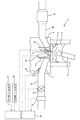
ここで、図2に基づいて、気筒2における点火プラグ5の配置について説明する。本実施例に係る筒内噴射弁61は、図2に示すように概ね放射状に16方向に燃料を噴射可能となるように噴孔61aを有している。そして、点火プラグ5の点火可能領域である電極間の領域5aに対して、噴孔61aから噴射された燃料噴霧の少なくとも一つが通過するように、且つ、その通過した噴霧に対して領域5aにおける電極間で生じた火花によって直接点火できるように、筒内噴射弁61に対する点火プラグ5の相対位置、特に筒内噴射弁61に対する領域5aの相対位置が決定されている。このように構成された点火プラグ5と筒内噴射弁61は、スプレーガイド燃焼を実現可能とする。すなわち、筒内噴射弁61および点火プラグ5は、内燃機関1の吸気弁9の開弁時期やピストン3の位置にかかわらず任意の時期に、領域5aを通過する燃料噴霧に対する点火を可能とする。なお、本実施例においては、点火プラグ5は、吸気弁9および排気弁10の動作に干渉しないように、2つの吸気ポート7の開口部の間に位置している。ただし、本発明に係る点火装置の位置は、2つの吸気ポートの開口部の間に限られるものではない。
Here, the arrangement of the spark plug 5 in the
ここで図1に戻ると、吸気ポート7は、吸気通路70と連通している。吸気通路70には、スロットル弁71が配置されている。スロットル弁71より上流の吸気通路70には、エアフローメータ72が配置されている。一方で、排気ポート8は、排気通路80と連通している。排気通路80には、内燃機関1から排出される排気を浄化するための排気浄化触媒81が配置されている。なお、後述するように、内燃機関1から排出される排気の空燃比は、ストイキ空燃比よりも高いリーン空燃比である。そのため、排気浄化触媒81としては、リーン空燃比の排気中のNOx浄化が可能な選択還元型のNOx触媒や排気中の粒子状物質(PM)を捕集可能なフィルタを採用することができる。
Returning to FIG. 1, the intake port 7 communicates with the
そして、内燃機関1には電子制御ユニット(ECU)20が併設されている。このECU20は内燃機関1の運転状態や排気浄化装置等を制御するユニットである。ECU20
には、上述したエアフローメータ72や、クランクポジションセンサ21及びアクセルポジションセンサ22が電気的に接続され、各センサの検出値がECU20に入力される。したがって、ECU20は、エアフローメータ72によって検出される吸入空気量、クランクポジションセンサ21の検出値に基づいて算出される機関回転速度、およびアクセルポジションセンサ22の検出値に基づく機関負荷等の内燃機関1の運転状態を把握可能である。また、ECU20には、筒内噴射弁61、ポート噴射弁62、点火プラグ5、およびスロットル弁71等が電気的に接続され、これらの各要素がECU20によって制御される。
The
The
<基本燃焼制御>
上記のように構成される内燃機関1において実行される基本的な燃焼制御である基本燃焼制御について、図3に基づいて説明する。図3は、図の左側から右側に進む時系列において、内燃機関1で行われる基本燃焼制御に関する燃料噴射及び点火の流れ(図3(a)の上段を参照)と、その燃料噴射及び点火により燃焼室で生じると想定される燃焼に関する事象の変遷(図3(a)の下段を参照)を模式的に示したものである。また、図3(b)には、図3(a)に示す燃料噴射であるプレ噴射とメイン噴射、および点火の時間的相関が示されている。なお、図3に示す形態は、あくまでも本実施例に係る基本燃焼制御を説明するために模式的に示したものであり、本発明をこの形態に限定して解釈すべきではない。
<Basic combustion control>
The basic combustion control, which is the basic combustion control executed in the
本実施例に係る基本燃焼制御では、1燃焼サイクルにおいて、筒内噴射弁61によってプレ噴射とメイン噴射とが実行される。プレ噴射は圧縮行程中に実行される燃料噴射である。メイン噴射は、プレ噴射よりも後の時期であって圧縮行程上死点(TDC)より前の時期に実行が開始される燃料噴射である。なお、メイン噴射は、TDCより前の時期に実行が開始されるが、TDC以降までその実行が継続されてもよい。そして、図3(b)に示すように、プレ噴射の噴射開始時期(以下、単に「プレ噴射時期」と称する)をTpとし、メイン噴射の噴射開始時期(以下、単に「メイン噴射時期」と称する)をTmとする。また、プレ噴射時期とメイン噴射時期との間隔(Tm−Tp)を第1噴射インターバルDi1と定義する。また、プレ噴射による燃焼は上述したスプレーガイド燃焼として実行される。つまり、プレ噴射によって噴射された燃料(以下、「プレ噴射燃料」と称する)によって形成されるプレ噴霧に対して点火プラグ5による点火が行われる。この点火時期を、図3(b)に示すようにTsとし、プレ噴射の実行が開始されてから点火が行われるまでの間隔(Ts−Tp)を点火インターバルDsと定義する。
In the basic combustion control according to the present embodiment, pre-injection and main injection are executed by the in-
次に、本発明に係る基本燃焼制御の流れについて説明する。
(1)プレ噴射
基本燃焼制御では、一燃焼サイクル中において、先ず、圧縮行程中のプレ噴射時期Tpにプレ噴射が行われる。なお、プレ噴射時期Tpは、後述するメイン噴射時期Tmとの相関に基づいて決定される。プレ噴射が実行されることで、図2に示すように、筒内噴射弁61から噴射されたプレ噴射燃料のプレ噴霧は、燃焼室内において点火プラグ5の点火可能領域5aを通過する。このようにプレ噴射の実行が開始された直後においては、プレ噴射燃料のプレ噴霧は燃焼室内に広く拡散はせずに、該噴霧の貫徹力によりその先端部において周囲の空気を巻き込みながら燃焼室内を進んでいく。そのため、プレ噴射燃料のプレ噴霧によって燃焼室内において成層混合気が形成される。
Next, the flow of basic combustion control according to the present invention will be described.
(1) Pre-injection In basic combustion control, pre-injection is first performed at pre-injection timing Tp during the compression stroke in one combustion cycle. Note that the pre-injection timing Tp is determined based on a correlation with a main injection timing Tm described later. By performing the pre-injection, as shown in FIG. 2, the pre-spray of the pre-injected fuel injected from the in-
(2)プレ噴射燃料への点火
そして、上記のように成層化されたプレ噴射燃料のプレ噴霧に対して、プレ噴射時期から所定の点火インターバルDsが経過した点火時期Tsに、点火プラグ5による点火が行われる。上記の通り、プレ噴射燃料は成層化されているため、該プレ噴射燃料量が少量であっても点火プラグ5周囲の局所的な空燃比は、当該点火による燃焼が可能な空燃比とな
っている。この点火により、プレ噴射燃料によるスプレーガイド燃焼が行われることになる。換言すれば、スプレーガイド燃焼が可能となるように点火インターバルDsが設定されている。そして、ピストン3の圧縮作用による圧力上昇に加えて、このスプレーガイド燃焼が行われることで、燃焼室内の更なる温度上昇が得られることになる。ただし、プレ噴射燃料のうち、このスプレーガイド燃焼によって燃焼する燃料は一部であり、そのうちの多くは点火プラグ5の点火による燃焼には供されずに該点火以後も「燃え残り燃料」として燃焼室内に存在することになる。これは、プレ噴射燃料によって形成された成層混合気における点火プラグ5の電極間から比較的離れた部分においては、その空燃比が高いために火炎が伝播できなくなるためである。ただし、当該燃え残り燃料は、燃焼室内でプレ噴射燃料の一部が燃焼することで高温雰囲気に晒されることになる。そのため、燃え残り燃料の少なくとも一部は燃焼には至らない状況下での低温酸化反応により燃焼性が高められた物性に改質された状態となることが期待される。ただし、本発明におけるプレ噴射燃料の燃え残りは、プレ噴射燃料の一部が点火プラグ5の点火による燃焼に供されずに該点火以後も燃焼室内に未燃の状態で残った燃料を指すものであり、その燃え残った燃料が特定の物性を示す状態になっていることが必ずしも要求されるものではない。
(2) Ignition to pre-injected fuel Then, with respect to the pre-spray of the pre-injected fuel stratified as described above, the ignition plug 5 is operated at an ignition timing Ts when a predetermined ignition interval Ds has elapsed from the pre-injection timing. Ignition is performed. As described above, since the pre-injected fuel is stratified, the local air-fuel ratio around the spark plug 5 becomes an air-fuel ratio that can be combusted by the ignition even if the amount of the pre-injected fuel is small. Yes. By this ignition, spray guide combustion by the pre-injected fuel is performed. In other words, the ignition interval Ds is set so that spray guide combustion is possible. In addition to the pressure increase due to the compression action of the piston 3, this spray guide combustion is performed, whereby a further temperature increase in the combustion chamber is obtained. However, a part of the pre-injected fuel is burned by this spray guide combustion, and most of the fuel is burned as “unburned fuel” after the ignition without being used for the combustion by the ignition of the spark plug 5. It will be in the room. This is because in the stratified mixture formed by the pre-injected fuel, the flame cannot be propagated at a portion relatively distant from the electrodes of the spark plug 5 because the air-fuel ratio is high. However, the unburned fuel is exposed to a high temperature atmosphere by burning a part of the pre-injected fuel in the combustion chamber. Therefore, it is expected that at least a part of the unburned fuel is in a state of being reformed to a physical property with improved combustibility by a low-temperature oxidation reaction under a situation where combustion does not occur. However, the remaining unburned pre-injected fuel in the present invention refers to fuel that remains in an unburned state in the combustion chamber after a part of the pre-injected fuel is not subjected to combustion by ignition of the spark plug 5. Therefore, it is not always required that the unburned fuel is in a state showing specific physical properties.
(3)メイン噴射
次に、プレ噴射時期から所定の第1噴射インターバルDi1が経過した圧縮行程上死点前のメイン噴射時期Tm(点火プラグ5による点火時期TsからDi1−Dsの時間が経過した時期Tm)に、筒内噴射弁61によるメイン噴射の実行が開始される。なお、内燃機関1においては、後述するようにメイン噴射燃料は自着火または拡散燃焼に供され、機関出力に寄与することになる。そのため、メイン噴射時期Tmは、機関負荷等によって決定される量のメイン噴射燃料の燃焼によって得られる機関出力が概ね最大となる時期(以下、「適正噴射時期」という)に設定される。ただし、メイン噴射燃料の燃焼は、プレ噴射燃料のプレ噴霧に対する点火によって生じた火炎を火種として開始される。つまり、メイン噴射時期Tmが適正噴射時期に設定されるとともに、プレ噴霧への点火によって生じた火炎を起点としてメイン噴射燃料の燃焼が開始されるように第1噴射インターバルDi1が設定されている。メイン噴射時期Tmと第1噴射インターバルDi1とがこのように設定されることで、プレ噴射時期Tpは必然的に決まることになる。そして、メイン噴射燃料の燃焼が開始されると燃焼室内の温度が更に上昇する。その結果、プレ噴射燃料の燃え残りとメイン噴射燃料とがその温度上昇場において自着火し、さらにはこれらの燃料が拡散燃焼に供されることになる。このとき、上記のようにプレ噴射燃料の燃え残りの燃焼性が高められている場合には、メイン噴射の実行開始後の燃料の自着火がより促進されることが期待される。
(3) Main injection Next, the main injection timing Tm before the top dead center of the compression stroke when the predetermined first injection interval Di1 has elapsed from the pre-injection timing (the time of Di1-Ds has elapsed from the ignition timing Ts by the spark plug 5) At time Tm), execution of main injection by the in-
ここで、図4に本実施例に係る基本燃焼制御が行われたときの燃焼室での熱発生率の推移を示す。なお、図4においては、4つの異なる制御形態L1〜L4に対応する熱発生率の推移が示されている。これらの制御形態L1〜L4においては、プレ噴射時期Tp、プレ噴射燃料量(すなわち、プレ噴射の実行期間)、メイン噴射時期Tm、点火時期Tsは同一となっているが、メイン噴射燃料量(すなわち、メイン噴射の実行期間)が制御形態ごとに異なっている。すなわち、メイン噴射燃料量は、L1>L2>L3>L4となっている。つまり、図4には、プレ噴射時期Tp、プレ噴射燃料量、メイン噴射時期Tm、および点火時期Tsを同一としたときのメイン噴射燃料量の増減に応じた熱発生率の推移の変化が示されていることになる。 Here, FIG. 4 shows the transition of the heat generation rate in the combustion chamber when the basic combustion control according to the present embodiment is performed. In addition, in FIG. 4, transition of the heat release rate corresponding to four different control forms L1-L4 is shown. In these control modes L1 to L4, the pre-injection timing Tp, the pre-injection fuel amount (that is, the pre-injection execution period), the main injection timing Tm, and the ignition timing Ts are the same, but the main injection fuel amount ( That is, the execution period of the main injection is different for each control mode. That is, the main injection fuel amount is L1> L2> L3> L4. That is, FIG. 4 shows changes in the change in the heat generation rate according to the increase or decrease in the main injection fuel amount when the pre-injection timing Tp, the pre-injection fuel amount, the main injection timing Tm, and the ignition timing Ts are the same. Will be.
ここで、図4中、点線で囲まれたZ1の部分で、熱発生率の一次ピークが表れている。この一次ピークは、プレ噴射燃料が点火によって燃焼することで発生した熱(つまり、スプレーガイド燃焼によって発生した熱)を示している。この熱発生率の一次ピークが表れる時期においては、メイン噴射はまだ行われておらず、燃焼室内にはプレ噴射燃料に対する点火によって生じた火炎と、該点火では燃焼していないプレ噴射燃料である燃え残り燃
料が存在していることになる。ここで、図5に基づいてプレ噴射燃料の燃え残りについて説明する。図5は、基本燃焼制御でのプレ噴射における、プレ噴射燃料量と、プレ噴射燃料の燃焼効率(以下、プレ燃焼効率と称する)との相関を、3つの燃焼条件L5〜L7のそれぞれについて示した図である。具体的には、L5、L6、L7の順で、燃焼条件であるプレ噴射時期Tpと点火時期Tsとが、両時期のインターバルである点火インターバルDsを一定とした状態で進角されている。なお、図5においては、メイン噴射は行われずに、プレ噴射及び点火のみ(つまり、スプレーガイド燃焼のみ)が行われた場合の上記相関が示されている。
Here, in FIG. 4, the primary peak of the heat generation rate appears in the portion Z1 surrounded by a dotted line. The primary peak indicates the heat generated by burning the pre-injected fuel by ignition (that is, heat generated by spray guide combustion). At the time when the primary peak of the heat generation rate appears, main injection has not yet been performed, and the combustion chamber is a flame generated by ignition of the pre-injected fuel, and pre-injected fuel not combusted by the ignition Unburned fuel is present. Here, the unburned residue of the pre-injected fuel will be described with reference to FIG. FIG. 5 shows the correlation between the amount of pre-injected fuel and the combustion efficiency of the pre-injected fuel (hereinafter referred to as pre-combustion efficiency) in each of the three combustion conditions L5 to L7 in the pre-injection in the basic combustion control. It is a figure. Specifically, the pre-injection timing Tp and the ignition timing Ts that are combustion conditions are advanced in the order of L5, L6, and L7 in a state where the ignition interval Ds that is an interval between both timings is constant. Note that FIG. 5 shows the above correlation when main injection is not performed and only pre-injection and ignition (that is, only spray guide combustion) are performed.
プレ燃焼効率は、プレ噴射燃料の燃え残り率と以下の式1に示す関連性を有する。つまり、プレ燃焼効率が高くなるほどプレ噴射燃料の燃え残り率は低くなる。
プレ噴射燃料の燃え残り率 = 1− プレ燃焼効率 ・・・(式1)
ここで、図5からは、プレ噴射燃料量が一定の場合に、プレ噴射時期Tpおよび点火時期Tsを進角させると(すなわち、第1噴射インターバルDi1を大きくすると)、プレ燃焼効率は下がり、故に燃え残り率は高くなる傾向が見出せる。また、プレ噴射燃料量を変化させた場合であっても、プレ噴射時期Tp及び点火時期Tsの進角量を調整することで、プレ燃焼効率と燃え残り率とを一定に制御することもできる。このように本実施例に係る基本燃焼制御では、プレ噴射燃料量と、プレ噴射時期Tpおよび点火時期Ts(すなわち、第1噴射インターバルDi)とを調整することで、プレ噴射燃料の燃え残り率を制御することができる。
The pre-combustion efficiency has a relationship represented by the
Unburned rate of pre-injected fuel = 1- Pre-combustion efficiency (Equation 1)
Here, from FIG. 5, when the pre-injection fuel amount is constant, if the pre-injection timing Tp and the ignition timing Ts are advanced (that is, if the first injection interval Di1 is increased), the pre-combustion efficiency decreases, Therefore, it can be found that the unburnt rate tends to be high. Even when the pre-injection fuel amount is changed, the pre-combustion efficiency and the unburned fuel ratio can be controlled to be constant by adjusting the advance amounts of the pre-injection timing Tp and the ignition timing Ts. . As described above, in the basic combustion control according to the present embodiment, the remaining amount rate of the pre-injected fuel is adjusted by adjusting the pre-injected fuel amount, the pre-injection timing Tp, and the ignition timing Ts (that is, the first injection interval Di). Can be controlled.
ここで、図4に戻ると、熱発生率の一次ピークが生じる時期よりも後であって圧縮行程上死点前の時期Tmにおいてメイン噴射の実行が開始される。このとき、メイン噴射燃料は、上述したように、先ずは、プレ噴射燃料のプレ噴霧に対する点火によって生じた火炎を火種として燃焼し始め、その後、プレ噴射燃料の燃え残りとともに自着火し、さらに拡散燃焼に供される。その結果、圧縮行程上死点を過ぎた時期に熱発生率の最大ピークである二次ピークが発生する。ここで、図4では、メイン噴射燃料量の増加にしたがって(すなわち、メイン噴射期間が長くなるのにしたがって)、熱発生率の二次ピークの値が大きくなるとともに、二次ピークの発生時期が遅くなっている。このことは、メイン噴射燃料量の増加にしたがってメイン噴射燃料の燃焼期間が長くなっていることを意味する。このことから、メイン噴射燃料およびプレ噴射燃料の燃え残りは、拡散燃焼もしくは実質的に拡散燃焼に同一視できる燃焼に供されているものと推察することができる。 Here, returning to FIG. 4, the execution of the main injection is started at a time Tm after the time when the primary peak of the heat generation rate occurs and before the top dead center of the compression stroke. At this time, as described above, the main injected fuel starts to burn using the flame generated by the ignition of the pre-injected fuel as a fire, then self-ignites with the unburned residue of the pre-injected fuel, and further diffuses. It is used for combustion. As a result, a secondary peak that is the maximum peak of the heat generation rate occurs at the time when the top dead center of the compression stroke has passed. Here, in FIG. 4, as the main injection fuel amount increases (that is, as the main injection period becomes longer), the value of the secondary peak of the heat generation rate increases and the generation time of the secondary peak It is late. This means that the combustion period of the main injected fuel becomes longer as the main injected fuel amount increases. From this, it can be inferred that the unburned residue of the main injection fuel and the pre-injection fuel is provided for diffusion combustion or combustion that can be substantially equated with diffusion combustion.
更に、図6に基づいて、本実施例に係る基本燃焼制御において発生する燃料の自着火について説明する。図6は、本実施例に係る基本燃焼制御において、一燃焼サイクル中の合計噴射量(プレ噴射燃料量とメイン噴射燃料量との合計)を一定としたままプレ噴射燃料量とメイン噴射燃料量との比率を変更した2つの形態L8,L9それぞれの、燃焼室内での熱発生比率の推移を示している。また、L9の形態の方がL8の形態に比べてプレ噴射燃料量の比率が高くなっている。すなわち、L9の形態の方がL8の形態に比べて、プレ噴射燃料量が多く、その結果、プレ噴射燃料の燃え残り量も多くなっている。この場合、図6に示すように、L9の形態では、L8の形態に比べて、圧縮行程上死点後の熱発生率の二次ピーク値が大きくなっている。さらに、L9の形態では、L8の形態に比べて、熱発生率の二次ピーク値からの立ち下り速度(二次ピーク以後のグラフの傾き)が大きくなっている。これらは、メイン噴射開始後のプレ噴射燃料の燃え残りおよびメイン噴射燃料の燃焼において、L9の形態では、L8の形態に比べて、自着火による燃焼がより促進されている(すなわち、自着火によって燃焼する燃料の割合が高くなり、拡散燃焼によって燃焼する燃料の割合が低くなっている)ことを意味するものと推察される。このことから、プレ噴射燃料の燃え残りがメイン噴射後の燃料の自着火の促進に寄与していると考えられる。また、本実施に係る基本燃焼制御において、プレ噴射燃料量以外にプレ噴射時期Tpや点火時期Tsを調整することでプレ噴射燃料の燃え残り量を多くした場合もメイン噴
射後の燃料の自着火が促進されていることを、本発明の発明者は確認した。つまり、本実施例に係る基本燃焼制御においては、プレ噴射や点火に関するパラメータを調整してプレ噴射燃料の燃え残り率を高めることで、メイン噴射実行開始後のプレ噴射燃料の燃え残りとメイン噴射燃料との燃焼において自着火を促進させることが可能である。
Furthermore, the self-ignition of fuel generated in the basic combustion control according to the present embodiment will be described based on FIG. FIG. 6 shows the pre-injected fuel amount and the main injected fuel amount in the basic combustion control according to the present embodiment while keeping the total injection amount (the total of the pre-injected fuel amount and the main injected fuel amount) in one combustion cycle constant. The transition of the heat generation ratio in the combustion chamber of each of the two forms L8 and L9 in which the ratio is changed is shown. Further, the ratio of the pre-injected fuel amount is higher in the L9 form than in the L8 form. That is, the L9 form has a larger amount of pre-injected fuel than the L8 form, and as a result, the unburned amount of the pre-injected fuel is also increased. In this case, as shown in FIG. 6, in the form of L9, the secondary peak value of the heat generation rate after the top dead center of the compression stroke is larger than in the form of L8. Furthermore, in the form of L9, the falling speed from the secondary peak value of the heat generation rate (the slope of the graph after the secondary peak) is larger than in the form of L8. In the combustion of the pre-injected fuel after the start of the main injection and the combustion of the main injected fuel, the combustion by self-ignition is more promoted in the L9 form than in the L8 form (that is, by self-ignition). It is presumed that this means that the proportion of fuel that burns is high and the proportion of fuel that burns by diffusion combustion is low. From this, it is considered that the unburned residue of the pre-injected fuel contributes to the promotion of self-ignition of the fuel after the main injection. Further, in the basic combustion control according to the present embodiment, the self-ignition of the fuel after the main injection is performed even when the remaining amount of the pre-injected fuel is increased by adjusting the pre-injection timing Tp and the ignition timing Ts in addition to the pre-injected fuel amount. The inventors of the present invention have confirmed that is promoted. That is, in the basic combustion control according to the present embodiment, by adjusting the parameters related to pre-injection and ignition to increase the unburned ratio of the pre-injected fuel, the unburned pre-injected fuel and the main injection after the start of the main injection execution It is possible to promote self-ignition in combustion with fuel.
以上説明したように、本実施例に係る基本燃焼制御では、プレ噴射と点火プラグ5での点火とによるスプレーガイド燃焼ののちにメイン噴射が実行されることで燃料の自着火および拡散燃焼を生じさせる。そのため、当該基本燃焼制御による燃焼はいわゆるディーゼル燃焼に類似し、又は実質的に同一視できると考えられる。したがって、燃焼室内の混合気の空燃比を極めて高いリーン空燃比(20〜70程度)とすることができる。また、このようなリーン空燃比での燃焼を実現するため、本実施例に係る燃焼制御では、従来のガソリンエンジンの燃焼制御(均質ストイキ制御)に比べてスロットル弁71の開度が大きくされる。そのため、内燃機関1でのポンプ損失を小さくすることができる。さらに、機関出力に寄与する燃焼が自着火および拡散燃焼により行われることで内燃機関1での冷却損失も従来の均質ストイキ制御時と比べて小さくすることができる。したがって、本実施例に係る基本燃焼制御によれば、従来のガソリンエンジンの燃焼制御では実現され得ない高い熱効率を達成することができる。
As described above, in the basic combustion control according to the present embodiment, the main injection is performed after the spray injection combustion by the pre-injection and the ignition by the spark plug 5, thereby causing the self-ignition and diffusion combustion of the fuel. Let Therefore, it is considered that the combustion by the basic combustion control is similar to so-called diesel combustion or can be substantially identified. Therefore, the air-fuel ratio of the air-fuel mixture in the combustion chamber can be set to an extremely high lean air-fuel ratio (about 20 to 70). Further, in order to realize combustion at such a lean air-fuel ratio, in the combustion control according to the present embodiment, the opening degree of the throttle valve 71 is made larger than that in the conventional gasoline engine combustion control (homogeneous stoichiometric control). . Therefore, the pump loss in the
また、上記のように、メイン噴射時期は内燃機関1の機関出力が概ね最大となる適正噴射時期に設定されている。そのため、メイン噴射燃料量を増量することによって機関負荷の上昇にある程度までは対応することができる。しかしながら、メイン噴射は、圧縮行程上死点近傍の燃焼室内の圧力が非常に高い時に行われるため、筒内噴射弁61から噴射された燃料噴霧のペネトレーションが小さくなる。つまり、メイン噴射によって噴射された燃料噴霧は広範囲に拡散し難い。そのため、メイン噴射燃料量が過剰に増量されると、メイン噴射燃料の噴霧の周囲に存在する酸素、即ち、メイン噴射燃料の燃焼に供される酸素の量が燃料に対して不足した状態となり、その結果、スモークの発生量が増加する虞がある。また、本実施例に係る基本燃焼制御では、メイン噴射後に燃料の自着火を生じさせる必要があるが、メイン噴射燃料量が過剰に多くなると、該メイン噴射燃料の気化潜熱によって燃焼室内の温度が低下し、燃焼が不安定となる虞もある。
Further, as described above, the main injection timing is set to an appropriate injection timing at which the engine output of the
一方、プレ噴射は圧縮行程中のプレ噴射時期Tpに行われる。そのため、プレ噴射燃料が点火プラグ5による点火によって燃焼すると内燃機関1の機関出力を妨げるように作用するとも考えられる。しかしながら、プレ噴射燃料のプレ噴霧への点火による燃焼では、メイン噴射燃料の燃焼のための火種となる火炎が形成されればよい。そのため、上記のように、プレ噴射燃料において、点火によって生じる火炎伝播による燃焼に供されるのは、そのうちの一部である。したがって、プレ噴射燃料のスプレーガイド燃焼による機関出力を妨げるような作用は小さい。そして、スプレーガイド燃焼には供されないプレ噴射燃料の燃え残りはメイン噴射後においてメイン噴射燃料とともに自着火または拡散燃焼に供されるため機関出力に寄与することになる。そのため、プレ噴射燃料量を増量するとともにその燃え残り率を上昇させることでも、機関負荷の上昇に対応することができる。
On the other hand, the pre-injection is performed at the pre-injection timing Tp during the compression stroke. Therefore, it is considered that when the pre-injected fuel is burned by ignition by the spark plug 5, it acts to hinder the engine output of the
また、メイン噴射時期においては、プレ噴射燃料の燃え残りは燃焼室内においてメイン噴射燃料の燃料噴霧よりも広範囲に拡散している。そのため、プレ噴射燃料の燃え残りが自着火または拡散燃焼に供される際には十分な酸素を確保し易い状態となっている。したがって、プレ噴射燃料の増量およびその燃え残り率の上昇により機関負荷の上昇に対応した場合、メイン噴射燃料量を増量した場合に比べてスモークの発生量を抑制することができる。 Further, at the main injection timing, the unburned residue of the pre-injected fuel is diffused in a wider range than the fuel spray of the main injected fuel in the combustion chamber. Therefore, it is easy to ensure sufficient oxygen when the unburned residue of the pre-injected fuel is subjected to self-ignition or diffusion combustion. Therefore, when the increase in the pre-injected fuel and the increase in the unburned fuel ratio correspond to the increase in engine load, the amount of smoke generated can be suppressed as compared with the case where the main injected fuel amount is increased.
<高負荷燃焼制御>
次に、本本実施例に係る内燃機関1での高負荷運転時における燃焼制御について説明す
る。本実施例に係る内燃機関1においては、機関負荷の上昇に従って燃焼室内への燃料噴射量を増量する必要がある。ただし、上述したように、メイン噴射燃料量が過剰に増量されると、スモークの発生量が増加したり、燃料の気化潜熱に起因して燃焼室内の温度が低下することで燃焼が不安定となったりする虞がある。また、上述したように、プレ噴射燃料量を増量する場合は、その増量とともにプレ噴射時期Tpを進角する、すなわち第1噴射インターバルDi1を大きくすることで、スモークの発生量を抑制することができる。しかしながら、プレ噴射燃料への点火によって生じる火炎をメイン噴射燃料の燃焼のための火種とする必要があることから、第1噴射インターバルDi1には上限値が存在する。
<High load combustion control>
Next, combustion control during high load operation in the
ここで、仮に、第1噴射インターバルDi1を当該上限値に維持した状態でプレ噴射燃料量を更に増量した場合、メイン噴射が実行された際に、燃焼室内においてメイン噴射燃料の噴霧が形成される位置に存在するプレ噴射燃料の燃え残り量が増加することになる。その結果、メイン噴射が実行された際にプレ噴射燃料の燃え残りとメイン噴射燃料とが重なり合うと、これらが重なり合った部分における燃料濃度が過剰に高くなる場合がある。この場合、当該部分の周囲に存在する酸素、即ち、当該部分に存在する燃料の燃焼に供される酸素の量が燃料に対して不足した状態となり、その結果、スモークが発生し易くなる。 Here, if the pre-injected fuel amount is further increased while the first injection interval Di1 is maintained at the upper limit value, when the main injection is executed, the spray of the main injected fuel is formed in the combustion chamber. The unburned amount of the pre-injected fuel existing at the position increases. As a result, when the unburned portion of the pre-injected fuel and the main injected fuel overlap when the main injection is executed, the fuel concentration in the overlapping portion may become excessively high. In this case, the amount of oxygen present around the portion, that is, the amount of oxygen provided for combustion of the fuel present in the portion becomes insufficient with respect to the fuel, and as a result, smoke is likely to be generated.
つまり、メイン噴射燃料量が増量される場合のみならず、プレ噴射燃料量についても、過剰に増量されると、スモークの発生量の増加を招く虞がある。そこで、本実施例においては、一燃焼サイクル中に燃焼室内に噴射する燃料量が比較的多く必要となる高負荷領域では、スモークの発生量を抑制すべく、上述した基本燃焼制御に代えて高負荷燃焼制御が行われる。以下、本実施例に係る高負荷燃焼制御について、図7に基づいて説明する。図7は、図の左側から右側に進む時系列において、内燃機関1で行われる高負荷燃焼制御に関する燃料噴射及び点火の流れ(図7(a)の上段を参照)と、その燃料噴射及び点火により燃焼室で生じると想定される燃焼に関する事象の変遷(図7(a)の下段を参照)を模式的に示したものである。また、図7(b)には、図7(a)に示す燃料噴射であるポート噴射、プレ噴射、およびメイン噴射と、点火との時間的相関が示されている。なお、図7に示す形態は、あくまでも本実施例に係る高負荷燃焼制御を説明するために模式的に示したものであり、本発明をこの形態に限定して解釈すべきではない。 In other words, not only when the main injection fuel amount is increased, but also when the pre-injection fuel amount is excessively increased, there is a risk of increasing the amount of smoke generated. Therefore, in the present embodiment, in a high load region where a relatively large amount of fuel is required to be injected into the combustion chamber during one combustion cycle, instead of the basic combustion control described above, a high amount is required to suppress the amount of smoke generated. Load combustion control is performed. Hereinafter, the high load combustion control according to the present embodiment will be described with reference to FIG. FIG. 7 shows the flow of fuel injection and ignition related to high-load combustion control performed in the internal combustion engine 1 (see the upper part of FIG. 7A) and the fuel injection and ignition in a time series that proceeds from the left side to the right side of the figure. 8 schematically shows the transition of events related to combustion assumed to occur in the combustion chamber (see the lower part of FIG. 7A). FIG. 7B shows a temporal correlation between the port injection, the pre-injection, and the main injection, which are the fuel injections shown in FIG. 7A, and ignition. It should be noted that the form shown in FIG. 7 is schematically shown only for explaining the high-load combustion control according to the present embodiment, and the present invention should not be interpreted as being limited to this form.
本実施例に係る高負荷燃焼制御は、プレ燃焼の形態が基本燃焼制御と異なっている。具体的には、基本燃焼制御では、上述したように、プレ燃焼のための燃料噴射を筒内噴射弁61によるプレ噴射によって行うのに対し、高負荷燃焼制御では、プレ燃焼のための燃料噴射をポート噴射弁62によるポート噴射および筒内噴射弁61によるプレ噴射を併用して行う。以下、基本燃焼制御に係るプレ燃焼を「第1プレ燃焼」と称し、高負荷燃焼制御に係るプレ燃焼を「第2プレ燃焼」と称する場合もある。
The high-load combustion control according to this embodiment is different from the basic combustion control in the pre-combustion mode. Specifically, in the basic combustion control, as described above, fuel injection for pre-combustion is performed by pre-injection by the in-
本実施例に係る高負荷燃焼制御では、図7に示すように、一燃焼サイクル中において、先ず、吸気行程中にポート噴射弁62によってポート噴射が実行される。ここで、図7(b)に示すように、ポート噴射の噴射開始時期(以下、単に「ポート噴射時期」と称する)をTptとする。ポート噴射時期Tptは、要求されているポート噴射燃料量を吸気行程中(すなわち、吸気弁9の開弁期間中)に噴射可能となる時期に設定される。このポート噴射が実行されることで、燃焼室内に混合気が形成されることになる。そして、次に、基本燃焼制御と同様、圧縮行程中のプレ噴射時期Tpに筒内噴射弁61によってプレ噴射が行われる。このプレ噴射が実行されることで、筒内噴射弁61から噴射されたプレ噴射燃料のプレ噴霧は、燃焼室内において点火プラグ5の点火可能領域5aを通過する。そして、この場合、ポート噴射燃料によって形成された混合気中にプレ噴霧が形成される。その結果、燃焼室内に成層混合気が形成されることになる。そして、圧縮行程における点火時期Tsにおいて、プレ噴霧に対して点火プラグ5による点火が行われる。この点火によ
って、プレ噴射燃料によるスプレーガイド燃焼が行われる。つまり、プレ噴射の実行が開始されてから点火が行われるまでの間隔である点火インターバルDsは、基本燃焼制御の場合と同様、スプレーガイド燃焼が可能となるように設定されている。
In the high load combustion control according to the present embodiment, as shown in FIG. 7, in one combustion cycle, first, port injection is executed by the
ここで、第2プレ燃焼では、基本燃焼制御における第1プレ燃焼と同様、メイン燃料の燃焼のための火種となる火炎が形成される程度の燃焼が行われればよい。ただし、本実施例に係る第2プレ燃焼では、ポート噴射燃料によって形成された混合気中にプレ噴射燃料によってプレ噴霧が形成され、該プレ噴霧に対し点火が行われることでスプレーガイド燃焼が行われる。そのため、スプレーガイド燃焼によって生じる火炎伝播によりポート噴射燃料も燃焼すると考えられる。このとき、ポート噴射燃料によって形成される混合気の空燃比が低すぎると、プレ噴射燃料によるスプレーガイド燃焼によって生じる火炎伝播により、過剰に多くのポート噴射燃料が燃焼してしまう虞がある。この場合、第2プレ燃焼によって燃焼したポート噴射燃料は内燃機関1の出力には寄与しないため、熱効率が低下することになる。そのため、ポート噴射燃料によって形成される均質混合気の空燃比が、プレ噴射燃料によるスプレーガイド燃焼によって生じる火炎伝播により燃焼するポート噴射燃料がポート噴射燃料量のうちの一部に抑えられる空燃比となるように、ポート噴射燃料量が設定されている。
Here, in the second pre-combustion, similarly to the first pre-combustion in the basic combustion control, it is only necessary to perform combustion to the extent that a flame that serves as a fire type for the combustion of the main fuel is formed. However, in the second pre-combustion according to the present embodiment, a pre-spray is formed by the pre-injected fuel in the air-fuel mixture formed by the port injected fuel, and the pre-spray is ignited to perform spray guide combustion. Is called. Therefore, it is considered that the port-injected fuel is also burned by flame propagation caused by spray guide combustion. At this time, if the air-fuel ratio of the air-fuel mixture formed by the port-injected fuel is too low, an excessive amount of port-injected fuel may be burned due to flame propagation caused by spray guide combustion with the pre-injected fuel. In this case, the port-injected fuel burned by the second pre-combustion does not contribute to the output of the
そして、プレ噴射時期から所定の第1噴射インターバルDi1が経過した圧縮行程上死点前のメイン噴射時期Tmに、筒内噴射弁61によるメイン噴射の実行が開始される。これにより、第2プレ燃焼によって生じた火炎を火種としてメイン噴射燃料の燃焼が開始される。メイン噴射燃料の燃焼が開始されると燃焼室内の温度が更に上昇する。その結果、ポート噴射燃料、プレ噴射燃料の燃え残り、および、メイン噴射燃料がその温度上昇場において自着火し、さらにはこれらの燃料が拡散燃焼に供されることになる。これにより、メイン燃焼が行われる。このとき、燃焼室内に存在するポート噴射燃料およびプレ噴射燃料の燃え残りが、第2プレ燃焼時に高温雰囲気に晒されることで燃焼性が高められている場合には、メイン噴射の実行開始後の燃料の自着火がより促進されることが期待される。
Then, execution of the main injection by the in-
上記のように、本実施例に係る高負荷燃焼制御においては、点火プラグ5による点火によって生じた火炎伝播では燃焼せずに燃え残ったポート噴射燃料およびプレ噴射燃料が、メイン燃料噴射後の自着火または拡散燃焼によって燃焼する。これにより、メイン噴射燃料に加え、ポート噴射燃料およびプレ噴射燃料も内燃機関1の出力に寄与することとなる。
As described above, in the high load combustion control according to the present embodiment, the port injection fuel and the pre-injected fuel that have not been burned by the flame propagation generated by the ignition by the spark plug 5 are left after the main fuel injection. It burns by ignition or diffusion combustion. Thereby, in addition to the main injection fuel, the port injection fuel and the pre-injection fuel also contribute to the output of the
そして、プレ噴射に加えてポート噴射を用いて第2プレ燃焼を行うことで、基本燃焼制御のようにプレ噴射のみを用いて第1プレ燃焼を行う場合に比べて、プレ噴射燃料量を減量することができる。したがって、ポート噴射とプレ噴射とを併用することで、同量の燃料をプレ噴射のみによって噴射した場合に比べて、スモークの発生量を抑制することができる。 Then, by performing the second pre-combustion using the port injection in addition to the pre-injection, the pre-injected fuel amount is reduced compared to the case where the first pre-combustion is performed using only the pre-injection as in the basic combustion control. can do. Therefore, by using the port injection and the pre-injection in combination, the amount of smoke generated can be suppressed as compared with the case where the same amount of fuel is injected only by the pre-injection.
また、混合気を形成するポート噴射燃料は、メイン噴射燃料よりも燃焼室内においてより広範囲に分布している。そのため、メイン燃焼時において、燃焼室内に存在する酸素のより多くを用いることができる。したがって、ポート噴射燃料の燃焼に必要な酸素を十分に確保することが可能となる。さらに、該ポート噴射燃料は、プレ噴射燃料の燃え残りと比べても、燃焼室内においてより広範囲に分布することなる。そのため、メイン噴射燃料とポート噴射燃料とが重なった部分の燃料濃度は、第1プレ燃焼を行った場合にメイン噴射燃料とプレ噴射燃料(燃え残り)とが重なった部分の燃料濃度より低くなる。そのため、メイン噴射燃料とポート噴射燃料とが重なったとしても、これらの燃料が重なった部分に存在する燃料の燃焼に供される酸素の量が不足した状態となることが抑制される。したがって、ポート噴射燃料は、メイン噴射燃料およびプレ噴射燃料のいずれと比べてもスモ
ークの発生原因となり難い。
Further, the port injection fuel forming the air-fuel mixture is distributed more widely in the combustion chamber than the main injection fuel. Therefore, more oxygen present in the combustion chamber can be used during main combustion. Therefore, it is possible to secure sufficient oxygen necessary for the combustion of the port injection fuel. Furthermore, the port-injected fuel is more widely distributed in the combustion chamber than the unburned residue of the pre-injected fuel. Therefore, the fuel concentration of the portion where the main injection fuel and the port injection fuel overlap is lower than the fuel concentration of the portion where the main injection fuel and the pre-injection fuel (unburned fuel) overlap when the first pre-combustion is performed. . Therefore, even if the main injection fuel and the port injection fuel overlap, it is suppressed that the amount of oxygen provided for the combustion of the fuel existing in the overlapping portion of these fuels becomes insufficient. Therefore, the port-injected fuel is unlikely to cause smoke as compared with either the main-injected fuel or the pre-injected fuel.
図8は、基本燃焼制御および高負荷燃焼制御における、内燃機関1の機関負荷と熱効率との相関(図8(a)を参照)、および、内燃機関1の機関負荷とスモークの発生量との相関(図8(b)を参照)を示す図である。図8(a)における線L10および図8(b)における線12は、高負荷燃焼制御におけるそれぞれの相関を示している。図8(a)における線L11および図8(b)における線13は、基本燃焼制御におけるそれぞれの相関を示している。図8(b)に示すように、基本燃焼制御では、内燃機関1機関負荷が所定負荷Qe0を超えるとスモークの発生量が急増する。そして、これに伴って、図8(a)に示すように、熱効率が低下することになる。これに対し、高負荷燃焼制御では、内燃機関1機関負荷が所定負荷Qe0を超えても、ある程度の機関負荷に達するまでは、スモークの発生量の増加を抑制することができる。そのため、内燃機関1機関負荷が所定負荷Qe0を超えても、熱効率を向上させることができる。
FIG. 8 shows the correlation between the engine load of the
以上説明したように、機関負荷が所定負荷よりも高い運転領域、すなわち、一燃焼サイクル中の総燃料噴射量が比較的多くなる運転領域では、第1プレ燃焼を行う基本燃焼制御に代えて、第2プレ燃焼を行う高負荷燃焼制御を実行することで、スモークの発生量を抑制しつつディーゼル燃焼を実現することができる。 As described above, in the operation region where the engine load is higher than the predetermined load, that is, in the operation region where the total fuel injection amount in one combustion cycle is relatively large, instead of the basic combustion control in which the first pre-combustion is performed, By executing the high-load combustion control that performs the second pre-combustion, diesel combustion can be realized while suppressing the amount of smoke generated.
<燃焼制御フロー>
ここで、本実施例に係る燃焼制御の制御フローについて図9に基づいて説明する。図9は、本実施例に係る燃焼制御の制御フローを示すフローチャートである。この制御フローは、ECU20に予め記憶されており、内燃機関1が稼働している間、ECU20に格納された制御プログラムが実行されることで、所定の間隔で繰り返し実行される。
<Combustion control flow>
Here, the control flow of the combustion control according to the present embodiment will be described with reference to FIG. FIG. 9 is a flowchart showing a control flow of combustion control according to the present embodiment. This control flow is stored in advance in the
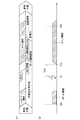
また、図10は、本実施例に係る燃焼制御に用いられる制御マップの一例を示している。図10の上段(a)では、内燃機関1の機関負荷とプレ噴射燃料量の相関を線L21で示し、該機関負荷とメイン噴射燃料量との相関を線L22で示し、該機関負荷とポート噴射燃料量との相関を線L23で示し、該機関負荷と該機関負荷に対応した燃料噴射量である負荷対応噴射量との相関を線L20で示している。また、図10(a)において、S1は、運転領域R3(以下、低負荷領域R3と称する)とR4(以下、中負荷領域R4と称する)との境界となる機関負荷に対応する燃料噴射量を表している(以下、第1所定量S1と称する)。また、S2(>S1)は、中負荷領域R4と運転領域R5(以下、高負荷領域R5と称する)との境界となる機関負荷に対応する燃料噴射量を表している(以下、第2所定量S2と称する)。そして、本実施例では、内燃機関1の機関負荷が低負荷領域R3または中負荷領域R4に属する場合は上記の基本燃焼制御が行われ、内燃機関1の機関負荷が高負荷領域R5に属する場合は上記の高負荷燃焼制御が行われる。つまり、本実施例では、中負荷領域R4と高負荷領域R5との境界となる機関負荷Qe0が、本発明に係る「所定負荷」に相当する。
FIG. 10 shows an example of a control map used for combustion control according to this embodiment. In the upper part (a) of FIG. 10, the correlation between the engine load of the
また、図10の下段(b)では、内燃機関1の機関負荷とプレ噴射時期Tpの相関を線L31で示し、該機関負荷と点火時期Tsとの相関を線L30で示し、該機関負荷とメイン噴射時期Tmとの相関を線L32で示し、該機関負荷とポート噴射時期Tptとの相関を線L33で示している。そして、線L31と線L32との間隔が第1噴射インターバルDi1を示し、線L31と線L30との間隔が点火インターバルDsを示している。なお、図10(b)の縦軸は圧縮行程上死点を基準としたクランク角(BTDC: Before Top Dead Center)を表しており、その値が大きくなるほど圧縮行程におけるより早い時期であることを意味する。
In the lower part (b) of FIG. 10, the correlation between the engine load of the
本実施例に係る制御フローでは、先ず、S101において、アクセルポジションセンサ
22の検出値に基づいて、内燃機関1の機関負荷Qeが算出される。また、別法として、吸気通路70を流れる空気流量、すなわちエアフローメータ72の検出値や、吸気通路70内の吸気圧力に基づいて、内燃機関1の機関負荷を算出することもできる。次に、S102において、S101で算出された機関負荷Qeに基づいて、負荷対応噴射量S0が算出される。具体的には、図10(a)で線L20に示す制御マップを利用して、機関負荷Qeに応じた負荷対応噴射量S0が算出される。なお、本実施例では、線L20で示すように、機関負荷が増加するに従い負荷対応噴射量S0が大きくなるように、両者の相関が制御マップ上に記録されている。
In the control flow according to the present embodiment, first, in S101, the engine load Qe of the
次に、S103において、S102で算出された負荷対応噴射量S0が第2所定量S2以下であるか否かが判別される。すなわち、S103において、内燃機関1の機関負荷Qeが、低負荷領域R3または中負荷領域R4に属しているのか、高負荷領域R5に属しているのかが判別される。S103において肯定判定された場合、すなわち、内燃機関1の機関負荷Qeが低負荷領域R3または中負荷領域R4に属している場合、基本燃焼制御を実行すべく、次にS104の処理が実行される。
Next, in S103, it is determined whether or not the load corresponding injection amount S0 calculated in S102 is equal to or smaller than a second predetermined amount S2. That is, in S103, it is determined whether the engine load Qe of the
S104では、図10に示す制御マップを用いて、基本燃焼制御を実現するための、プレ噴射燃料量Sp、メイン噴射燃料量Sm、プレ噴射時期Tp、メイン噴射時期Tm、および点火時期Tsが決定される。 In S104, the pre-injection fuel amount Sp, the main injection fuel amount Sm, the pre-injection timing Tp, the main injection timing Tm, and the ignition timing Ts for realizing basic combustion control are determined using the control map shown in FIG. Is done.
ここで、低負荷領域R3または中負荷領域R4において基本燃焼制御を実現するための各制御パラメータの値について説明する。負荷対応噴射量S0が第1所定量S1以下である場合、すなわち、内燃機関1の機関負荷が低負荷領域R3に属する場合、図10(a)で線L21に示すように、プレ噴射燃料量Spが最小プレ噴射燃料量Spminに設定される。ここで、最小プレ噴射燃料量Spminは、メイン噴射が実行された際にメイン噴射燃料の燃焼開始のための火種となる火炎を形成することが可能なプレ噴射燃料量の下限値である。ここで、プレ噴射燃料量Spが多くなると、点火プラグ5での点火による燃焼(即ちスプレーガイド燃焼)が促進され易くなるためプレ噴射燃料における燃え残り率が低下する虞があるが、プレ噴射燃料量Spを最小プレ噴射燃料量Spminとすることでその燃え残り率を可及的に高くすることができる。そのため、低負荷領域R3では、プレ噴射燃料量Spを最小プレ噴射燃料量Spminとすることで、安定した燃焼を確保しつつ高い熱効率を実現することができる。また、低負荷領域R3は、負荷対応噴射量が比較的少ないため、機関負荷の増加に対してメイン噴射燃料量Smのみの増量によって対応しても、スモークの発生量が増加したり、メイン噴射燃料の気化潜熱に起因して燃焼が不安定となったりする可能性が低い運転領域として設定されている。そこで、図10(a)に示すように、低負荷領域R3では、機関負荷の増加に対してはメイン噴射燃料量Smのみの増加によって対応し、プレ噴射燃料量Spは最小プレ噴射燃料量Spminで固定される。
Here, the value of each control parameter for realizing the basic combustion control in the low load region R3 or the medium load region R4 will be described. When the load corresponding injection amount S0 is equal to or less than the first predetermined amount S1, that is, when the engine load of the
また、メイン噴射時期Tmは、内燃機関1の熱効率を向上させるために圧縮行程上死点前の適正噴射時期に設定される。そして、低負荷領域R3では、適正噴射時期に設定されたメイン噴射時期Tmに対し、プレ噴射燃料量Spが最小プレ噴射燃料量Spminである場合に熱効率が好適な状態となる第1噴射インターバルDi1が確保されるように、プレ噴射時期Tpが設定される。なお、上述のように、低負荷領域R3では、プレ噴射燃料量Spは最小プレ噴射燃料量Spminで固定される。そのため、低負荷領域R3では、第1噴射インターバルDi1も一定に維持される。したがって、図10(b)に示すように、低負荷領域R3では、機関負荷が変動することでメイン噴射燃料量Smが変動し、それに伴ってメイン噴射時期Tmが変動した場合、当該メイン噴射時期Tmの変動に連動してプレ噴射時期Tpも変動することになる。
Further, the main injection timing Tm is set to an appropriate injection timing before the compression stroke top dead center in order to improve the thermal efficiency of the
また、図10(b)に示すように、プレ噴射時期Tpと点火時期Tsとのインターバルである点火インターバルDsは一定に維持される。そのため、低負荷領域R3では、メイン噴射時期Tmの変動に連動してプレ噴射時期Tpが変動した場合、当該変動に連動して点火時期Tsも変動することになる。 As shown in FIG. 10B, the ignition interval Ds that is the interval between the pre-injection timing Tp and the ignition timing Ts is maintained constant. Therefore, in the low load region R3, when the pre-injection timing Tp varies in conjunction with the variation in the main injection timing Tm, the ignition timing Ts also varies in conjunction with the variation.
また、低負荷領域R3では、線L22で示される負荷対応噴射量S0とメイン噴射燃料量Smとの相関は、以下の式2に従う。
Sm = S0 −Sp×α ・・・(式2)
α:プレ噴射燃料の燃え残り率
上記のとおり、本実施例に係る基本燃焼制御では、プレ噴射燃料の燃え残りはメイン噴射燃料とともに自着火し拡散燃焼に供されることで機関出力に寄与する。そのため、機関出力に寄与するという観点に立てば、プレ噴射燃料の燃え残りはメイン噴射燃料と同等と言うことができる。そこで、プレ噴射燃料の燃え残り率を示す係数αを予め実験等で求めておき、当該係数αを考慮した上記式2に従ってメイン噴射燃料量Smを算出することで、適切なメイン噴射燃料量Smを求めることができる。なお、プレ噴射燃料の燃え残り率は、点火インターバルDs及び第1噴射インターバルDi1に応じて変化する。従って、係数αはこれらに基づいて定まる値である。そして、低負荷領域R3では、点火インターバルDs及び第1噴射インターバルDi1はいずれも一定であるため、上記式2おける係数αも一定値となる。また、低負荷領域R3では、上記の理由によりプレ噴射燃料量Spは最小プレ噴射燃料量Spminに固定されるため、上記式2においてSp=Spminとなる。また、プレ噴射燃料量に対して点火プラグ5による点火によって燃焼する分の燃料量(すなわち第1プレ燃焼によって燃焼する分の燃料量)が非常に少ない場合は、制御上、係数α=1としてもよい。
Further, in the low load region R3, the correlation between the load corresponding injection amount S0 and the main injected fuel amount Sm indicated by the line L22 follows the following
Sm = S0−Sp × α (Expression 2)
α: Remaining unburned rate of pre-injected fuel As described above, in the basic combustion control according to the present embodiment, the unburned unburned pre-injected fuel is self-ignited together with the main injected fuel and is used for diffusion combustion, thereby contributing to engine output . Therefore, from the viewpoint of contributing to the engine output, it can be said that the unburned residue of the pre-injected fuel is equivalent to the main injected fuel. Therefore, an appropriate main injection fuel amount Sm is obtained by calculating a coefficient α indicating the unburned ratio of the pre-injected fuel in advance through experiments or the like and calculating the main injection fuel amount Sm according to the
また、中負荷領域R4は、機関負荷の増加に対してメイン噴射燃料量Smのみの増量によって対応した場合、スモークの発生量が増加したり、メイン噴射燃料の気化潜熱に起因して燃焼が不安定となったりする可能性が高い運転領域として設定されている。そのため、中負荷領域R4では、機関負荷の増加に対してメイン噴射燃料量Smのみならずプレ噴射燃料量Spも増量することで対応する。したがって、中負荷領域R4では、図10(b)で線L21に示すように、内燃機関1の機関負荷が高いほどプレ噴射燃料量Spは増量される。これにより、内燃機関1の機関負荷が高いほど、プレ噴射燃料の燃え残り量が多くなる。そして、内燃機関1の機関負荷が、中負荷領域R4における最大機関負荷である所定負荷Qe0のときに、プレ噴射燃料量Spが最大プレ噴射燃料量Spmaxとなる。
In the middle load region R4, when the increase in the engine load is dealt with by the increase in the main injection fuel amount Sm alone, the amount of smoke generated increases or the combustion does not occur due to the vaporization latent heat of the main injection fuel. It is set as an operation region where there is a high possibility of becoming stable. Therefore, in the medium load region R4, an increase in engine load is dealt with by increasing not only the main injection fuel amount Sm but also the pre-injection fuel amount Sp. Therefore, in the middle load region R4, as indicated by a line L21 in FIG. 10B, the pre-injected fuel amount Sp is increased as the engine load of the
また、中負荷領域R4では、図10(a)で線L22に示すように、内燃機関1の機関負荷が高いほどメイン噴射燃料量Smも増量される。なお、中負荷領域R4でも、低負荷領域R3と同様に、線L22で示される負荷対応噴射量S0とメイン噴射燃料量Smとの相関は、上記式2に従う。また、上記のように、中負荷領域R4では、機関負荷の上昇に従いプレ噴射燃料量Spが増量される。そのため、図10(a)で線L22に示すように、該中負荷領域R4におけるメイン噴射燃料量Smの増量比率(機関負荷の上昇量に対するメイン噴射燃料量Smの増加量の比率)は、プレ噴射燃料量Spが固定されている低負荷領域R3におけるメイン噴射燃料量Smの増量比率よりも小さくなる。これにより、メイン噴射燃料量の増量に起因するスモークの発生量の増加や、メイン噴射燃料の気化潜熱の増加に起因する失火の発生を抑制することができる。
In the middle load region R4, as indicated by a line L22 in FIG. 10A, the main injection fuel amount Sm increases as the engine load of the
また、中負荷領域R4では、図10(b)に示すように、内燃機関1の機関負荷が高いほど、第1噴射インターバルDi1が大きくなるようにプレ噴射時期Tpが進角される。つまり、中負荷領域R4では、プレ噴射時期Tpが、メイン噴射時期Tmの進角量に連動した進角量以上に進角され、その進角量が、機関負荷が高いほど大きくなっている。このようにプレ噴射時期Tpを制御することで、プレ噴射燃料量Spが増量されることでその
燃え残り量が多くなっても、プレ噴射燃料の燃え残りとメイン噴射燃料とが重なった部分の燃料濃度をより低くすることができる。その結果、これらの燃料の重なりに起因するスモークの発生量を抑制することができる。
In the middle load region R4, as shown in FIG. 10B, the pre-injection timing Tp is advanced so that the first injection interval Di1 becomes larger as the engine load of the
また、図10(b)に示すように、中負荷領域R4においても、低負荷領域R3と同様、プレ噴射時期Tpと点火時期Tsとのインターバルである点火インターバルDsは一定に維持される。そのため、機関負荷の上昇に従い、プレ噴射時期Tpがメイン噴射時期Tmの進角量に連動した進角量以上に進角された場合、点火時期Tsもプレ噴射時期Tpと同程度に進角される。 As shown in FIG. 10 (b), also in the middle load region R4, as in the low load region R3, the ignition interval Ds that is the interval between the pre-injection timing Tp and the ignition timing Ts is maintained constant. Therefore, as the engine load increases, when the pre-injection timing Tp is advanced beyond the advance amount linked to the advance amount of the main injection timing Tm, the ignition timing Ts is also advanced to the same extent as the pre-injection timing Tp. The
図9に示すフローチャートの説明に戻り、S104において図10に示す制御マップを用いて基本燃焼制御を実現するための各制御パラメータの値が決定されると、次にS105の処理が実行される。S105においては、S104で決定されたプレ噴射燃料量Sp、メイン噴射燃料量Sm、プレ噴射時期Tp、メイン噴射時期Tm、および点火時期Tsに従って、筒内噴射弁61によるプレ噴射およびメイン噴射と、点火プラグ5による点火とが実行される。これにより、本実施例に係る基本燃焼制御が実現される。
Returning to the description of the flowchart shown in FIG. 9, when the values of the respective control parameters for realizing the basic combustion control are determined using the control map shown in FIG. 10 in S104, the process of S105 is executed next. In S105, according to the pre-injection fuel amount Sp, the main injection fuel amount Sm, the pre-injection timing Tp, the main injection timing Tm, and the ignition timing Ts determined in S104, pre-injection and main injection by the in-
一方、S103において否定判定された場合、すなわち、内燃機関1の機関負荷Qeが高負荷領域R5に属している場合、高負荷燃焼制御を実行すべく、次にS106の処理が実行される。
On the other hand, if a negative determination is made in S103, that is, if the engine load Qe of the
S106では、図10に示す制御マップを用いて、高負荷燃焼制御を実現するための、ポート噴射燃料量Spt、プレ噴射燃料量Sp、メイン噴射燃料量Sm、ポート噴射時期Tpt、プレ噴射時期Tp、メイン噴射時期Tm、および点火時期Tsが決定される。 In S106, the port injection fuel amount Spt, the pre-injection fuel amount Sp, the main injection fuel amount Sm, the port injection timing Tpt, and the pre-injection timing Tp for realizing the high load combustion control using the control map shown in FIG. The main injection timing Tm and the ignition timing Ts are determined.
ここで、高負荷領域R5において高負荷燃焼制御を実現するための各制御パラメータの値について説明する。図10(a)で線L21および線L22に示すように、高負荷領域R5では、プレ噴射量Spおよびメイン噴射量Smは一定量に固定される。このとき、プレ噴射量Spは、中負荷領域R4における最大プレ噴射燃料量Spmaxよりも最小ポート噴射量(内燃機関1の機関負荷がQe0のときのポート噴射量)分少ない量に固定される。また、メイン噴射量Smは、中負荷領域R4における最大メイン噴射燃料量Smmaxに固定される。そして、高負荷領域R5では、機関負荷の増加に対してメイン噴射燃料量Smの増加によって対応する。また、このときのポート噴射燃料量Sptは、ポート噴射燃料によって形成される混合気の空燃比が、プレ噴射燃料によるスプレーガイド燃焼によって生じる火炎伝播により燃焼するポート噴射燃料がポート噴射燃料量のうちの一部に抑えられる空燃比となるように設定されている。
Here, the value of each control parameter for realizing the high load combustion control in the high load region R5 will be described. As indicated by lines L21 and L22 in FIG. 10A, in the high load region R5, the pre-injection amount Sp and the main injection amount Sm are fixed to a constant amount. At this time, the pre-injection amount Sp is fixed to an amount smaller by the minimum port injection amount (port injection amount when the engine load of the
ここで、図10(a)で線L23に示される、高負荷領域R5における負荷対応噴射量S0とポート噴射燃料量Sptとの相関は、以下の式3に従う。
Spt = (S0 −(Sp×α´ + Sm))/β´ ・・・(式3)
α´:プレ噴射燃料の燃え残り率
β´:ポート噴射燃料の燃え残り率
α´およびβ´はポート噴射とプレ噴射とを併用して第2プレ燃焼を行った場合のそれぞれの燃料の燃え残り率である。これらの燃え残り率は実験等に基づいて求めることができる。上記のとおり、ポート噴射燃料の多くはメイン噴射燃料とともに自着火または拡散燃焼に供されることで機関出力に寄与する。しかしながら、第2プレ燃焼において燃焼するポート噴射燃料の一部は機関出力には寄与しないこととなる。そこで、高負荷領域R5では、上記式3により、プレ噴射燃料の燃え残り率のみならずポート噴射燃料の燃え残り率(すなわち、ポート噴射燃料量における、点火プラグ5による点火では燃焼せずにメイン噴射後の自着火または拡散燃焼に供される分の割合)を考慮してポート噴射燃料量Sp
tが決定される。これにより、適切なポート噴射燃料量Sptを求めることができる。ただし、上記式2における係数αと同様、プレ噴射燃料量に対して点火プラグ5による点火によって燃焼する分の燃料量(すなわち第2プレ燃焼によって燃焼する分の燃料量)が非常に少ない場合は、制御上、係数α´=1としてもよい。また、ポート噴射燃料量に対して点火プラグ5によるプレ噴霧への点火によって燃焼する分の燃料量(すなわち第2プレ燃焼によって燃焼する分の燃料量)が非常に少ない場合は、制御上、係数β´=1としてもよい。
Here, the correlation between the load corresponding injection amount S0 and the port injected fuel amount Spt in the high load region R5 indicated by the line L23 in FIG.
Spt = (S0− (Sp × α ′ + Sm)) / β ′ (Expression 3)
α ′: Remaining unburned ratio of pre-injected fuel β ′: Unburned unburned ratio of port injected fuel α ′ and β ′ are burned of each fuel when the second pre-combustion is performed using both port injection and pre-injection. It is the remaining rate. These unburned residue rates can be obtained based on experiments and the like. As described above, most of the port-injected fuel contributes to the engine output by being subjected to self-ignition or diffusion combustion together with the main-injected fuel. However, part of the port injection fuel combusted in the second pre-combustion does not contribute to the engine output. Therefore, in the high load region R5, according to the above equation 3, not only the pre-injected fuel unburned rate but also the port injected fuel unburned rate (that is, the port injected fuel amount is not burned by ignition with the spark plug 5 but main combustion). Port injection fuel amount Sp considering the ratio of auto-ignition after injection or diffusion combustion)
t is determined. Thereby, an appropriate port injection fuel amount Spt can be obtained. However, as in the case of the coefficient α in the
また、高負荷領域R5では、プレ噴射燃料量Spおよびメイン噴射燃料量Smが一定量に固定されるため、図10(b)の線L31およびL32に示すように、プレ噴射時期Tpおよびメイン噴射時期Tmもそれぞれの噴射量に適した一定の時期に固定される。また、高負荷領域R5においても、点火インターバルDsは一定に維持される。そのため、図10(b)の線L30に示すように、点火時期Tsは一定の時期に固定される。これにより、高負荷領域R5におけるプレ噴射燃料の燃え残り量も概ね一定となる。また、上述したように、ポート噴射時期Tptは、要求されているポート噴射燃料量Sptを吸気行程中(すなわち、吸気弁9の開弁期間中)に噴射可能となる時期に設定される。そのため、図10(b)の線L33に示すように、ポート噴射時期Tptは、機関負荷の変動に伴うポート噴射量Sptの変動に応じて変動する。 Further, in the high load region R5, the pre-injection fuel amount Sp and the main injection fuel amount Sm are fixed to a constant amount. Therefore, as shown by lines L31 and L32 in FIG. The time Tm is also fixed at a certain time suitable for each injection amount. Further, the ignition interval Ds is kept constant even in the high load region R5. Therefore, as indicated by a line L30 in FIG. 10B, the ignition timing Ts is fixed at a constant timing. As a result, the remaining amount of the pre-injected fuel in the high load region R5 is also substantially constant. Further, as described above, the port injection timing Tpt is set to a timing at which the required port injection fuel amount Spt can be injected during the intake stroke (that is, during the valve opening period of the intake valve 9). Therefore, as indicated by a line L33 in FIG. 10B, the port injection timing Tpt varies according to the variation of the port injection amount Spt accompanying the variation of the engine load.
図9に示すフローチャートの説明に戻り、S106において高負荷燃焼制御を実現するための各制御パラメータの値が決定されると、次にS107の処理が実行される。S107においては、S106で決定されたポート噴射燃料量Spt、プレ噴射燃料量Sp、メイン噴射燃料量Sm、ポート噴射時期Tpt、プレ噴射時期Tp、メイン噴射時期Tm、および点火時期Tsに従って、ポート噴射弁62によるポート噴射と、筒内噴射弁61によるプレ噴射およびメイン噴射と、点火プラグ5による点火とが実行される。これにより、本実施例に係る高負荷燃焼制御が実現される。
Returning to the description of the flowchart shown in FIG. 9, when the values of the respective control parameters for realizing the high load combustion control are determined in S106, the process of S107 is executed next. In S107, the port injection fuel amount Spt, the pre-injection fuel amount Sp, the main injection fuel amount Sm, the port injection timing Tpt, the pre-injection timing Tp, the main injection timing Tm, and the ignition timing Ts determined in S106. Port injection by the
なお、図10は、あくまで、本実施例に係る燃焼制御に用いられる制御マップの一例であって、内燃機関の機関負荷と、基本燃焼制御および高負荷燃焼制御における各制御パラメータとの相関は該図10に示すものに限られるものではない。 FIG. 10 is merely an example of a control map used for the combustion control according to the present embodiment. The correlation between the engine load of the internal combustion engine and each control parameter in the basic combustion control and the high load combustion control is shown in FIG. It is not restricted to what is shown in FIG.
本実施例に係る内燃機関およびその吸排気系の概略構成は実施例1と同様である。また、本実施例においても、実施例1と同様の基本燃焼制御が行われる。ただし、本実施例においては、高負荷領域において実行される高負荷燃焼制御の制御形態が実施例1とは異なっている。 The schematic configuration of the internal combustion engine and its intake / exhaust system according to this embodiment is the same as that of the first embodiment. Also in the present embodiment, the basic combustion control similar to that in the first embodiment is performed. However, in this embodiment, the control mode of the high load combustion control executed in the high load region is different from that of the first embodiment.
以下、本実施例に係る高負荷燃焼制御について、図11に基づいて説明する。図11は、図の左側から右側に進む時系列において、内燃機関1で行われる高負荷燃焼制御に関する燃料噴射及び点火の流れ(図11(a)の上段を参照)と、その燃料噴射及び点火により燃焼室で生じると想定される燃焼に関する事象の変遷(図11(a)の下段を参照)を模式的に示したものである。また、図11(b)には、図11(a)に示す燃料噴射であるポート噴射およびメイン噴射と、点火の時間的相関が示されている。なお、図11に示す形態は、あくまでも本実施例に係る高負荷燃焼制御を説明するために模式的に示したものであり、本発明をこの形態に限定して解釈すべきではない。 Hereinafter, the high load combustion control according to the present embodiment will be described with reference to FIG. FIG. 11 shows the flow of fuel injection and ignition related to high-load combustion control performed in the internal combustion engine 1 (see the upper part of FIG. 11 (a)), and the fuel injection and ignition in the time series from the left to the right in the figure. FIG. 12 schematically shows the transition of events related to combustion assumed to occur in the combustion chamber (see the lower part of FIG. 11A). FIG. 11B shows the temporal correlation between the port injection and the main injection, which are the fuel injections shown in FIG. In addition, the form shown in FIG. 11 is schematically shown in order to explain the high load combustion control according to the present embodiment, and the present invention should not be interpreted as being limited to this form.
本実施例に係る高負荷燃焼制御は、第2プレ燃焼の形態が実施例1に係る高負荷燃焼制御とは異なっている。具体的には、実施例1に係る高負荷燃焼制御においては、第2プレ燃焼のための燃料噴射をポート噴射弁62によるポート噴射および筒内噴射弁61によるプレ噴射の両方によって行うのに対し、本実施例に係る高負荷燃焼においては、第2プレ
燃焼のための燃料噴射をポート噴射弁62によるポート噴射のみによって行う。
The high load combustion control according to this embodiment is different from the high load combustion control according to the first embodiment in the form of the second pre-combustion. Specifically, in the high load combustion control according to the first embodiment, the fuel injection for the second pre-combustion is performed by both the port injection by the
本実施例に係る高負荷燃焼制御では、図11に示すように、一燃焼サイクル中において、先ず、吸気行程中のポート噴射時期Tptにポート噴射弁62によってポート噴射が実行される。ここで、ポート噴射時期Tptは、実施例1に係る高負荷燃焼制御の場合と同様、要求されているポート噴射燃料量を吸気行程中(すなわち、吸気弁9の開弁期間中)に噴射可能となる時期に設定される。このポート噴射が実行されることで、燃焼室内に混合気が形成されることになる。そして、圧縮行程における点火時期Tsにおいて、この混合気に対して点火プラグ5による点火が行われる。この点火によって混合気を形成するポート噴射燃料の一部が燃焼することで、第2プレ燃焼が行われることになる。
In the high load combustion control according to the present embodiment, as shown in FIG. 11, in one combustion cycle, port injection is first executed by the
ここで、本実施例に係る第2プレ燃焼でも、実施例1に係る第2プレ燃焼と同様、メイン燃料の燃焼のための火種となる火炎が形成される程度の燃焼が行われればよい。しかしながら、ポート噴射燃料によって形成される混合気の空燃比が高すぎると点火プラグ5による点火が行われても、燃料が着火しない虞がある。この場合、メイン噴射を実行してもメイン燃焼を行うことができないため、失火してしまうことになる。一方で、該混合気の空燃比が低すぎると、点火プラグ5による点火によって生じる火炎伝播により、過剰に多くのポート噴射燃料が燃焼してしまう虞がある。この場合、第2プレ燃焼によって燃焼したポート噴射燃料は内燃機関1の出力には寄与しないため、熱効率が低下することになる。そのため、ポート噴射燃料によって形成される混合気の空燃比が、点火プラグ5による点火によって燃料が着火することで火炎は生じるが、該火炎の伝播ではポート噴射燃料の一部のみが燃焼する空燃比となるように、ポート噴射燃料量が設定されている。
Here, even in the second pre-combustion according to the present embodiment, it is only necessary to perform the combustion to such an extent that a flame serving as a fire type for the combustion of the main fuel is formed as in the second pre-combustion according to the first embodiment. However, if the air-fuel ratio of the air-fuel mixture formed by the port injection fuel is too high, the fuel may not be ignited even if ignition is performed by the spark plug 5. In this case, even if the main injection is executed, the main combustion cannot be performed, so that misfire occurs. On the other hand, if the air-fuel ratio of the air-fuel mixture is too low, excessive port injection fuel may be burned due to flame propagation caused by ignition by the spark plug 5. In this case, the port-injected fuel burned by the second pre-combustion does not contribute to the output of the
そして、点火プラグ5による点火から所定の第2噴射インターバルDi2が経過した圧縮行程上死点前のメイン噴射時期Tmに、筒内噴射弁61によるメイン噴射の実行が開始される。これにより、第2プレ燃焼によって生じた火炎を火種としてメイン噴射燃料の燃焼が開始される。換言すれば、第2プレ燃焼によって生じた火炎を起点としてメイン噴射燃料の燃焼が開始されるように第2噴射インターバルDi2が設定されている。また、基本燃焼制御と同様、高負荷燃焼制御においても、メイン噴射時期Tmは適正噴射時期に設定される。メイン噴射時期Tmと第2噴射インターバルDi2とがこのように設定されることで、点火時期Tsは必然的に決まることになる。
Then, execution of main injection by the in-
メイン噴射燃料の燃焼が開始されると燃焼室内の温度が更に上昇する。その結果、ポート噴射燃料とメイン噴射燃料とがその温度上昇場において自着火し、さらにはこれらの燃料が拡散燃焼に供されることになる。これにより、メイン燃焼が行われる。このとき、燃焼室内に存在するポート噴射燃料が、第2プレ燃焼時に高温雰囲気に晒されることで、第1プレ燃焼におけるプレ噴射燃料の燃え残りと同様に燃焼性が高められている場合には、メイン噴射の実行開始後の燃料の自着火がより促進されることが期待される。 When combustion of the main injection fuel is started, the temperature in the combustion chamber further increases. As a result, the port-injected fuel and the main-injected fuel are self-ignited in the temperature rising field, and these fuels are further subjected to diffusion combustion. Thereby, main combustion is performed. At this time, when the port-injected fuel existing in the combustion chamber is exposed to a high-temperature atmosphere during the second pre-combustion, the combustibility is enhanced in the same way as the unburned fuel remaining in the first pre-combustion. It is expected that the self-ignition of the fuel after the start of the main injection is further promoted.
上記のように、高負荷燃焼制御においては、点火プラグ5による点火によって生じた火炎伝播では燃焼せずに燃え残ったポート噴射燃料は、基本燃焼制御におけるプレ噴射燃料の燃え残りと同様、メイン燃料噴射後の自着火または拡散燃焼によって燃焼する。これにより、メイン噴射燃料に加え、ポート噴射燃料も内燃機関1の出力に寄与することとなる。また、上述したように、ポート噴射燃料は、メイン噴射燃料のみならず、プレ噴射燃料と比べてもスモークの発生原因となり難い。そのため、ポート噴射を用いてプレ燃焼を行うことで、スモークの発生量を抑制することができる。
As described above, in the high-load combustion control, the port injection fuel that remains unburned in the flame propagation generated by the ignition by the spark plug 5 is the main fuel, similar to the unburned pre-injection fuel in the basic combustion control. It burns by self-ignition after injection or diffusion combustion. Thereby, in addition to the main injection fuel, the port injection fuel also contributes to the output of the
したがって、機関負荷が所定負荷よりも高い運転領域、すなわち、一燃焼サイクル中の総燃料噴射量が比較的多くなる運転領域では、上記のような高負荷燃焼制御を実行することで、実施例1に係る高負荷燃焼制御を実行した場合と同様に、スモークの発生量を抑制
しつつディーゼル燃焼を実現することができる。
Therefore, in the operation region where the engine load is higher than the predetermined load, that is, in the operation region where the total fuel injection amount during one combustion cycle is relatively large, the high load combustion control as described above is executed, so that the first embodiment is performed. As in the case of performing the high load combustion control according to the above, diesel combustion can be realized while suppressing the amount of smoke generated.
<燃焼制御フロー>
ここで、本実施例に係る燃焼制御の制御フローについて図12に基づいて説明する。図12は、本実施例に係る燃焼制御の制御フローを示すフローチャートである。この制御フローは、ECU20に予め記憶されており、内燃機関1が稼働している間、ECU20に格納された制御プログラムが実行されることで、所定の間隔で繰り返し実行される。なお、本制御フローにおけるS101〜105は、図9に示すフローにおける各ステップと同一である。そのため、図9に示すフローと同一の処理が実行されるステップについては同一の参照番号を付し、その説明を省略する。
<Combustion control flow>
Here, the control flow of the combustion control according to the present embodiment will be described with reference to FIG. FIG. 12 is a flowchart showing a control flow of combustion control according to the present embodiment. This control flow is stored in advance in the
また、図13は、本実施例に係る燃焼制御に用いられる制御マップの一例を示している。図13の上段(a)では、図10(a)と同様、内燃機関1の機関負荷とプレ噴射燃料量の相関を線L21で示し、該機関負荷とメイン噴射燃料量との相関を線L22で示し、該機関負荷とポート噴射燃料量との相関を線L23で示し、該機関負荷と該機関負荷に対応した燃料噴射量である負荷対応噴射量との相関を線L20で示している。また、図13の下段(b)では、図10(b)と同様、内燃機関1の機関負荷とプレ噴射時期Tpの相関を線L31で示し、該機関負荷と点火時期Tsとの相関を線L30で示し、該機関負荷とメイン噴射時期Tmとの相関を線L32で示し、該機関負荷とポート噴射時期Tptとの相関を線L33で示している。そして、線L31と線L32との間隔が第1噴射インターバルDi1を示し、線L31と線L30との間隔が点火インターバルDsを示している。また、図13の下段(b)においては、線L30と線L32との間隔が第2噴射インターバルDi2を示している。
FIG. 13 shows an example of a control map used for combustion control according to this embodiment. In the upper part (a) of FIG. 13, as in FIG. 10 (a), the correlation between the engine load of the
本実施例においても、実施例1と同様、内燃機関1の機関負荷が、低負荷領域R3または中負荷領域R4に属する場合は、基本燃焼制御が行われ、高負荷領域R5に属する場合は高負荷燃焼制御が行われる。つまり、本実施例においても、中負荷領域R4と高負荷領域R5との境界となる機関負荷Qe0が、本発明に係る「所定負荷」に相当する。
Also in the present embodiment, as in the first embodiment, the basic combustion control is performed when the engine load of the
本実施例に係る制御フローにおいても、S103で肯定判定された場合、すなわち、内燃機関1の機関負荷Qeが低負荷領域R3または中負荷領域R4に属している場合は、実施例1と同様、S104およびS105の処理が実行されることで基本燃焼制御が実現される。一方、S103で否定判定された場合、すなわち、内燃機関1の機関負荷Qeが高負荷領域R5に属している場合、高負荷燃焼制御を実行すべく、次にS206の処理が実行される。
Also in the control flow according to the present embodiment, when an affirmative determination is made in S103, that is, when the engine load Qe of the
S206では、図13に示す制御マップを用いて、高負荷燃焼制御を実現するための、ポート噴射燃料量Spt、メイン噴射燃料量Sm、ポート噴射時期Tpt、メイン噴射時期Tm、および点火時期Tsが決定される。 In S206, the port injection fuel amount Spt, the main injection fuel amount Sm, the port injection timing Tpt, the main injection timing Tm, and the ignition timing Ts for realizing the high load combustion control using the control map shown in FIG. It is determined.
ここで、高負荷領域R5において高負荷燃焼制御を実現するための各制御パラメータの値について説明する。図13(a)で線L23に示すように、高負荷領域R5では、ポート噴射燃料量Sptは一定量に固定される。そして、上述したように、このときのポート噴射燃料量Sptは、ポート噴射燃料によって形成される混合気の空燃比が、点火プラグ5による点火によって燃料が着火することで火炎は生じるが、該火炎の伝播ではポート噴射燃料の一部のみが燃焼する空燃比となるように設定されている。また、高負荷領域R5において、ポート噴射燃料量Sptは一定量に固定されるため、ポート噴射時期Tptも一定時期に固定される。上述したように、このときのポート噴射時期Tptは、要求されているポート噴射燃料量Sptを吸気行程中(すなわち、吸気弁9の開弁期間中)に噴射可能となる時期に設定されている。 Here, the value of each control parameter for realizing the high load combustion control in the high load region R5 will be described. As indicated by a line L23 in FIG. 13A, the port injection fuel amount Spt is fixed to a constant amount in the high load region R5. As described above, the port injection fuel amount Spt at this time is determined by the fact that the air-fuel ratio of the air-fuel mixture formed by the port injection fuel is ignited by the ignition of the spark plug 5, and the flame is generated. Is set so that only a part of the port-injected fuel has an air-fuel ratio to burn. In the high load region R5, since the port injection fuel amount Spt is fixed to a constant amount, the port injection timing Tpt is also fixed to a constant time. As described above, the port injection timing Tpt at this time is set to a timing at which the required port injection fuel amount Spt can be injected during the intake stroke (that is, during the valve opening period of the intake valve 9). .
また、高負荷領域R5では、機関負荷の増加に対してメイン噴射燃料量Smの増加によって対応する。図13(a)で線L22に示される、高負荷領域R5における負荷対応噴射量S0とメイン噴射燃料量Smとの相関は、以下の式4に従う。
Sm = S0 −Spt×β ・・・(式4)
β:ポート噴射燃料の燃え残り率
βはポート噴射のみを用いて第2プレ燃焼を行った場合のポート噴射燃料の燃え残り率である。この燃え残り率は実験等に基づいて求めることができる。上記式4によれば、ポート噴射燃料の燃え残り率を考慮してメイン噴射燃料量Smが決定されている。これにより、適切なメイン噴射燃料量Smを求めることができる。ただし、上記式3における係数β´と同様、ポート噴射燃料量に対して点火プラグ5によるプレ噴霧への点火によって燃焼する分の燃料量(すなわち第2プレ燃焼によって燃焼する分の燃料量)が非常に少ない場合は、制御上、係数β=1としてもよい。
Further, in the high load region R5, an increase in the engine load corresponds to an increase in the main injection fuel amount Sm. The correlation between the load corresponding injection amount S0 and the main injection fuel amount Sm in the high load region R5 indicated by a line L22 in FIG.
Sm = S0−Spt × β (Formula 4)
β: Unburned rate of port injected fuel β is the unburned rate of port injected fuel when second pre-combustion is performed using only port injection. This unburned residue rate can be obtained based on experiments and the like. According to the above equation 4, the main injected fuel amount Sm is determined in consideration of the unburned ratio of the port injected fuel. Thereby, an appropriate main injection fuel amount Sm can be obtained. However, the amount of fuel combusted by ignition of the pre-spray by the spark plug 5 with respect to the port injection fuel amount (that is, the amount of fuel combusted by the second pre-combustion) is the same as the coefficient β ′ in Equation 3 above. If it is very small, the coefficient β = 1 may be set for control.
また、高負荷領域R5においても、メイン噴射時期Tmは圧縮行程上死点前の適正噴射時期に設定される。したがって、図13(b)で線L32に示すように、メイン噴射時期Tmは、機関負荷の変動に伴うメイン噴射燃料量Smの変動に応じて変動する。そして、高負荷領域R5においては、図13(b)に示すように、点火時期Tsとメイン噴射時期Tmとのインターバルである第2噴射インターバルDi2が一定に維持される。そのため、高負荷領域R5では、図13(b)で線L30に示すように、メイン噴射時期Tmの変動に連動して点火時期Tsが変動することになる。 Also in the high load region R5, the main injection timing Tm is set to an appropriate injection timing before the top dead center of the compression stroke. Accordingly, as indicated by a line L32 in FIG. 13B, the main injection timing Tm varies according to the variation of the main injection fuel amount Sm accompanying the variation of the engine load. In the high load region R5, as shown in FIG. 13B, the second injection interval Di2 that is the interval between the ignition timing Ts and the main injection timing Tm is maintained constant. Therefore, in the high load region R5, as indicated by a line L30 in FIG. 13B, the ignition timing Ts varies in conjunction with the variation of the main injection timing Tm.
図12に示すフローチャートの説明に戻り、S206において高負荷燃焼制御を実現するための各制御パラメータの値が決定されると、次にS207の処理が実行される。S207においては、S206で決定されたポート噴射燃料量Spt、メイン噴射燃料量Sm、ポート噴射時期Tpt、メイン噴射時期Tm、および点火時期Tsに従って、ポート噴射弁62によるポート噴射と、筒内噴射弁61によるメイン噴射と、点火プラグ5による点火とが実行される。これにより、本実施例に係る高負荷燃焼制御が実現される。
Returning to the description of the flowchart shown in FIG. 12, when the value of each control parameter for realizing the high load combustion control is determined in S206, the process of S207 is executed next. In S207, in accordance with the port injection fuel amount Spt, the main injection fuel amount Sm, the port injection timing Tpt, the main injection timing Tm, and the ignition timing Ts determined in S206, the port injection by the
なお、図13は、あくまで、本実施例に係る燃焼制御に用いられる制御マップの一例であって、内燃機関の機関負荷と、基本燃焼制御および高負荷燃焼制御における各制御パラメータとの相関は該図13に示すものに限られるものではない。 FIG. 13 is merely an example of a control map used for the combustion control according to the present embodiment, and the correlation between the engine load of the internal combustion engine and each control parameter in the basic combustion control and the high load combustion control is shown in FIG. It is not restricted to what is shown in FIG.
また、上記実施例2においては、ポート噴射のみを用いた第2プレ燃焼を高負荷領域で行うものとした。しかしながら、第2プレ燃焼を低負荷領域または中負荷領域で行うこともできる。この場合、低負荷領域または中負荷領域でのスモークの発生量をより抑制することが可能となる。ただし、低負荷領域または中負荷領域では、一燃焼サイクル中の総燃料噴射量が比較的少ないため、十分な量のポート噴射燃料量を確保することが困難となり、ポート噴射燃料によって形成される混合気の空燃比が過剰に高くなる場合もある。この場合、プレ燃焼時における燃料の着火性が低下し、その結果、失火を招きやすくなる。したがって、プレ燃焼時における燃料の着火性の観点からすると、上記実施例2のように、低負荷領域または中負荷領域では、プレ噴射を用いた第1プレ燃焼を行うことが好ましい。 In the second embodiment, the second pre-combustion using only port injection is performed in the high load region. However, the second pre-combustion can be performed in a low load region or a medium load region. In this case, it is possible to further suppress the amount of smoke generated in the low load region or the medium load region. However, in the low load region or the medium load region, since the total fuel injection amount during one combustion cycle is relatively small, it is difficult to secure a sufficient amount of port injection fuel, and the mixing formed by the port injection fuel is difficult. In some cases, the air-fuel ratio of the gas becomes excessively high. In this case, the ignitability of the fuel during pre-combustion is reduced, and as a result, misfire is likely to occur. Therefore, from the viewpoint of fuel ignitability during pre-combustion, it is preferable to perform the first pre-combustion using pre-injection in the low load region or the medium load region as in the second embodiment.
また、上記実施例1および2に係る高負荷燃焼制御では、ポート噴射を吸気行程中(すなわち、吸気弁9の開弁期間中)に実行するものとした。しかしながら、高負荷燃焼制御では、ポート噴射を実行することで燃焼室内に混合気が形成されればよい。そのため、第2プレ燃焼のためのポート噴射を排気行程中(すなわち、吸気弁9の閉弁期間中)に実行してもよい。この場合でも、ポート噴射弁62によって吸気ポート7内に噴射された燃料が、吸気行程において吸入空気と共に気筒2内に流入する。これにより、燃焼室内に混合
気が形成される。
In the high load combustion control according to the first and second embodiments, the port injection is executed during the intake stroke (that is, during the valve opening period of the intake valve 9). However, in high-load combustion control, it is only necessary to form an air-fuel mixture in the combustion chamber by executing port injection. Therefore, the port injection for the second pre-combustion may be executed during the exhaust stroke (that is, during the closing period of the intake valve 9). Even in this case, the fuel injected into the intake port 7 by the
1・・・内燃機関
2・・・気筒
3・・・ピストン
5・・点火プラグ
61・・筒内噴射弁
62・・ポート噴射弁
7・・・吸気ポート
8・・・排気ポート
9・・・吸気弁
10・・排気弁
20・・ECU
21・・クランクポジションセンサ
22・・アクセルポジションセンサ
71・・スロットル弁
72・・エアフローメータ
DESCRIPTION OF
21 ·· Crank
Claims (3)
内燃機関の吸気ポート内に燃料を噴射可能なポート噴射弁と、
前記筒内噴射弁から噴射された噴霧が点火可能領域を通過し該噴霧に直接に点火可能となるように、該筒内噴射弁に対する相対位置が決定された点火装置と、
内燃機関の機関負荷が所定負荷以下の運転領域において、圧縮行程中に前記筒内噴射弁によってプレ噴射を実行するとともに該プレ噴射によって形成されるプレ噴霧に対し前記点火装置によって点火を行うことで該プレ噴射によって噴射された燃料の一部を燃焼させて第1プレ燃焼を行う第1プレ燃焼部と、
内燃機関の機関負荷が前記所定負荷より高い運転領域において、排気行程または吸気行程中に前記ポート噴射弁によってポート噴射を実行することで混合気を形成させるとともに、圧縮行程中に前記筒内噴射弁によってプレ噴射を実行することで該混合気中にプレ噴霧を形成させ、さらに、該プレ噴霧に対し前記点火装置によって点火を行うことで該第プレ噴射によって噴射された燃料の一部および該ポート噴射によって噴射された燃料の一部を燃焼させて第2プレ燃焼を行う第2プレ燃焼部と、
前記第1プレ燃焼または前記第2プレ燃焼の発生後であり且つ圧縮行程上死点前の時期であって、前記第1プレ燃焼または前記第2プレ燃焼によって生じた火炎を起点として噴射燃料の燃焼が開始されるように設定されたメイン噴射時期に前記筒内噴射弁によるメイン噴射の実行を開始することで、燃料の自着火を発生させるとともに少なくとも該メイン噴射によって噴射された燃料の一部を拡散燃焼させてメイン燃焼を行うメイン燃焼部と、を備える内燃機関の制御装置。 An in-cylinder injection valve capable of injecting fuel into the combustion chamber of the internal combustion engine;
A port injection valve capable of injecting fuel into the intake port of the internal combustion engine;
An ignition device whose relative position to the in-cylinder injection valve is determined such that the spray injected from the in-cylinder injection valve passes through the ignitable region and can be directly ignited.
By performing pre-injection by the in-cylinder injection valve during the compression stroke and igniting the pre-spray formed by the pre-injection by the ignition device in an operation region where the engine load of the internal combustion engine is equal to or less than a predetermined load. A first pre-combustion unit that performs a first pre-combustion by burning part of the fuel injected by the pre-injection;
In the operating region where the engine load of the internal combustion engine is higher than the predetermined load, the air-fuel mixture is formed by executing the port injection by the port injection valve during the exhaust stroke or the intake stroke, and the in-cylinder injection valve during the compression stroke A pre-injection is formed in the air-fuel mixture by performing pre-injection, and a part of the fuel injected by the first pre-injection by igniting the pre-spray by the ignition device and the port A second pre-combustion unit that performs a second pre-combustion by burning part of the fuel injected by the injection;
After the occurrence of the first pre-combustion or the second pre-combustion and before the top dead center of the compression stroke, the fuel generated by the first pre-combustion or the second pre-combustion is used as a starting point. By starting execution of main injection by the in-cylinder injection valve at the main injection timing set to start combustion, fuel self-ignition is generated and at least a part of the fuel injected by the main injection A control device for an internal combustion engine, comprising: a main combustion section that performs main combustion by diffusively burning the fuel.
内燃機関の吸気ポート内に燃料を噴射可能なポート噴射弁と、
前記筒内噴射弁から噴射された噴霧が点火可能領域を通過し該噴霧に直接に点火可能となるように、該筒内噴射弁に対する相対位置が決定された点火装置と、
排気行程または吸気行程中に前記ポート噴射弁によってポート噴射を実行することで混合気を形成させるとともに、圧縮行程中に燃焼室内において該混合気に対し前記点火装置によって点火を行うことで該ポート噴射によって噴射された燃料の一部を燃焼させてプレ燃焼を行うプレ燃焼部と、
前記プレ燃焼の発生後であり且つ圧縮行程上死点前の時期であって、前記プレ燃焼によって生じた火炎を起点として噴射燃料の燃焼が開始されるように設定されたメイン噴射時期に前記筒内噴射弁によるメイン噴射の実行を開始することで、燃料の自着火を発生させるとともに少なくとも該メイン噴射によって噴射された燃料の一部を拡散燃焼させてメイン燃焼を行うメイン燃焼部と、を備える内燃機関の制御装置。 An in-cylinder injection valve capable of injecting fuel into the combustion chamber of the internal combustion engine;
A port injection valve capable of injecting fuel into the intake port of the internal combustion engine;
An ignition device whose relative position to the in-cylinder injection valve is determined such that the spray injected from the in-cylinder injection valve passes through the ignitable region and can be directly ignited.
By performing port injection by the port injection valve during the exhaust stroke or intake stroke, an air-fuel mixture is formed, and during the compression stroke, the air-fuel mixture is ignited by the ignition device in the combustion chamber. A pre-combustion section that performs pre-combustion by burning a part of the fuel injected by
After the pre-combustion has occurred and before the compression stroke top dead center, the cylinder is set at the main injection timing set so that the combustion of the injected fuel is started from the flame generated by the pre-combustion. A main combustion section for starting main injection by the inner injection valve to cause self-ignition of the fuel and at least partially diffusively burn the fuel injected by the main injection to perform main combustion Control device for internal combustion engine.
圧縮行程中に前記筒内噴射弁によってプレ噴射を実行するとともに該プレ噴射によって形成されるプレ噴霧に対し前記点火装置によって点火を行うことで該プレ噴射によって噴射された燃料の一部を燃焼させて第1プレ燃焼を行う第1プレ燃焼部をさらに備え、
内燃機関の機関負荷が所定負荷以下の運転領域では、前記第1プレ燃焼部が前記第1プレ燃焼を行い、
内燃機関の機関負荷が前記所定負荷より高い運転領域では、前記第2プレ燃焼部が前記第2プレ燃焼を行い、
前記メイン燃焼部が、前記第1プレ燃焼または前記第2プレ燃焼の発生後であり且つ圧縮行程上死点前の時期であって、前記第1プレ燃焼または前記第2プレ燃焼によって生じた火炎を起点として噴射燃料の燃焼が開始されるように設定されたメイン噴射時期に前記筒内噴射弁によるメイン噴射の実行を開始することで、前記メイン燃焼を行う請求項2に記載の内燃機関の制御装置。 The pre-combustion part is a second pre-combustion part, and the pre-combustion is a second pre-combustion;
During the compression stroke, pre-injection is performed by the in-cylinder injection valve, and a part of the fuel injected by the pre-injection is burned by igniting the pre-spray formed by the pre-injection by the ignition device. And further comprising a first pre-combustion unit that performs first pre-combustion,
In an operation region where the engine load of the internal combustion engine is equal to or less than a predetermined load, the first pre-combustion unit performs the first pre-combustion,
In an operation region where the engine load of the internal combustion engine is higher than the predetermined load, the second pre-combustion unit performs the second pre-combustion,
A flame generated by the first pre-combustion or the second pre-combustion at a time after the occurrence of the first pre-combustion or the second pre-combustion and before the compression stroke top dead center. 3. The internal combustion engine according to claim 2, wherein the main combustion is performed by starting execution of the main injection by the in-cylinder injection valve at a main injection timing set so that combustion of the injected fuel is started from the starting point. Control device.
Priority Applications (1)
| Application Number | Priority Date | Filing Date | Title |
|---|---|---|---|
| JP2014238943A JP2016098794A (en) | 2014-11-26 | 2014-11-26 | Internal combustion engine control device |
Applications Claiming Priority (1)
| Application Number | Priority Date | Filing Date | Title |
|---|---|---|---|
| JP2014238943A JP2016098794A (en) | 2014-11-26 | 2014-11-26 | Internal combustion engine control device |
Publications (1)
| Publication Number | Publication Date |
|---|---|
| JP2016098794A true JP2016098794A (en) | 2016-05-30 |
Family
ID=56076634
Family Applications (1)
| Application Number | Title | Priority Date | Filing Date |
|---|---|---|---|
| JP2014238943A Pending JP2016098794A (en) | 2014-11-26 | 2014-11-26 | Internal combustion engine control device |
Country Status (1)
| Country | Link |
|---|---|
| JP (1) | JP2016098794A (en) |
Cited By (1)
| Publication number | Priority date | Publication date | Assignee | Title |
|---|---|---|---|---|
| US11834983B2 (en) | 2019-07-15 | 2023-12-05 | The Research Foundation For The State University Of New York | Method for control of advanced combustion through split direct injection of high heat of vaporization fuel or water fuel mixtures |
-
2014
- 2014-11-26 JP JP2014238943A patent/JP2016098794A/en active Pending
Cited By (1)
| Publication number | Priority date | Publication date | Assignee | Title |
|---|---|---|---|---|
| US11834983B2 (en) | 2019-07-15 | 2023-12-05 | The Research Foundation For The State University Of New York | Method for control of advanced combustion through split direct injection of high heat of vaporization fuel or water fuel mixtures |
Similar Documents
| Publication | Publication Date | Title |
|---|---|---|
| JP6225938B2 (en) | Control device for internal combustion engine | |
| JP6056776B2 (en) | Control device for internal combustion engine | |
| JP6229598B2 (en) | Control device for internal combustion engine | |
| JP6269410B2 (en) | Control device for internal combustion engine | |
| JP4404154B2 (en) | Fuel injection control device for internal combustion engine | |
| JP6056775B2 (en) | Control device for internal combustion engine | |
| JP6206364B2 (en) | Internal combustion engine | |
| JP2016089747A (en) | Control device of internal combustion engine | |
| JP2009299490A (en) | Fuel injection control device for internal combustion engine | |
| JP2016000969A5 (en) | ||
| JP2010196526A (en) | Combustion control device of compression-ignition internal combustion engine | |
| JP5321160B2 (en) | Combustion control device for compression ignition type internal combustion engine | |
| JP2016098794A (en) | Internal combustion engine control device | |
| JP2006052686A (en) | Control device of internal combustion engine | |
| JP2009293596A (en) | Fuel injection control device for internal combustion engine | |
| JP2016200080A (en) | Control device for internal combustion engine | |
| JP5282603B2 (en) | Combustion control device for compression ignition type internal combustion engine | |
| JP6304183B2 (en) | Control device for internal combustion engine | |
| JP4973602B2 (en) | Fuel injection control device for internal combustion engine | |
| JP2010196528A (en) | Combustion control device of compression-ignition internal combustion engine | |
| JP2006132390A (en) | Control device for diesel engine | |
| JP2008038719A (en) | Spark ignition internal combustion engine |